EP3781925B1 - Assembling machine and assembly method for coupling to two sample-holders the ends of an elastomer specimen to be subjected to dynamic mechanical-thermal analysis - Google Patents
Assembling machine and assembly method for coupling to two sample-holders the ends of an elastomer specimen to be subjected to dynamic mechanical-thermal analysis Download PDFInfo
- Publication number
- EP3781925B1 EP3781925B1 EP19723872.8A EP19723872A EP3781925B1 EP 3781925 B1 EP3781925 B1 EP 3781925B1 EP 19723872 A EP19723872 A EP 19723872A EP 3781925 B1 EP3781925 B1 EP 3781925B1
- Authority
- EP
- European Patent Office
- Prior art keywords
- sample
- specimen
- vice
- holders
- assembling machine
- Prior art date
- Legal status (The legal status is an assumption and is not a legal conclusion. Google has not performed a legal analysis and makes no representation as to the accuracy of the status listed.)
- Active
Links
Images



Classifications
-
- G—PHYSICS
- G01—MEASURING; TESTING
- G01N—INVESTIGATING OR ANALYSING MATERIALS BY DETERMINING THEIR CHEMICAL OR PHYSICAL PROPERTIES
- G01N3/00—Investigating strength properties of solid materials by application of mechanical stress
- G01N3/02—Details
- G01N3/04—Chucks
-
- B—PERFORMING OPERATIONS; TRANSPORTING
- B23—MACHINE TOOLS; METAL-WORKING NOT OTHERWISE PROVIDED FOR
- B23P—METAL-WORKING NOT OTHERWISE PROVIDED FOR; COMBINED OPERATIONS; UNIVERSAL MACHINE TOOLS
- B23P19/00—Machines for simply fitting together or separating metal parts or objects, or metal and non-metal parts, whether or not involving some deformation; Tools or devices therefor so far as not provided for in other classes
- B23P19/008—Machines for simply fitting together or separating metal parts or objects, or metal and non-metal parts, whether or not involving some deformation; Tools or devices therefor so far as not provided for in other classes the parts being continuously transported through the machine during assembling or disassembling
-
- B—PERFORMING OPERATIONS; TRANSPORTING
- B23—MACHINE TOOLS; METAL-WORKING NOT OTHERWISE PROVIDED FOR
- B23P—METAL-WORKING NOT OTHERWISE PROVIDED FOR; COMBINED OPERATIONS; UNIVERSAL MACHINE TOOLS
- B23P19/00—Machines for simply fitting together or separating metal parts or objects, or metal and non-metal parts, whether or not involving some deformation; Tools or devices therefor so far as not provided for in other classes
- B23P19/04—Machines for simply fitting together or separating metal parts or objects, or metal and non-metal parts, whether or not involving some deformation; Tools or devices therefor so far as not provided for in other classes for assembling or disassembling parts
-
- B—PERFORMING OPERATIONS; TRANSPORTING
- B23—MACHINE TOOLS; METAL-WORKING NOT OTHERWISE PROVIDED FOR
- B23P—METAL-WORKING NOT OTHERWISE PROVIDED FOR; COMBINED OPERATIONS; UNIVERSAL MACHINE TOOLS
- B23P21/00—Machines for assembling a multiplicity of different parts to compose units, with or without preceding or subsequent working of such parts, e.g. with program control
- B23P21/004—Machines for assembling a multiplicity of different parts to compose units, with or without preceding or subsequent working of such parts, e.g. with program control the units passing two or more work-stations whilst being composed
-
- B—PERFORMING OPERATIONS; TRANSPORTING
- B23—MACHINE TOOLS; METAL-WORKING NOT OTHERWISE PROVIDED FOR
- B23P—METAL-WORKING NOT OTHERWISE PROVIDED FOR; COMBINED OPERATIONS; UNIVERSAL MACHINE TOOLS
- B23P19/00—Machines for simply fitting together or separating metal parts or objects, or metal and non-metal parts, whether or not involving some deformation; Tools or devices therefor so far as not provided for in other classes
- B23P19/04—Machines for simply fitting together or separating metal parts or objects, or metal and non-metal parts, whether or not involving some deformation; Tools or devices therefor so far as not provided for in other classes for assembling or disassembling parts
- B23P19/06—Screw or nut setting or loosening machines
-
- G—PHYSICS
- G01—MEASURING; TESTING
- G01N—INVESTIGATING OR ANALYSING MATERIALS BY DETERMINING THEIR CHEMICAL OR PHYSICAL PROPERTIES
- G01N35/00—Automatic analysis not limited to methods or materials provided for in any single one of groups G01N1/00 - G01N33/00; Handling materials therefor
- G01N35/02—Automatic analysis not limited to methods or materials provided for in any single one of groups G01N1/00 - G01N33/00; Handling materials therefor using a plurality of sample containers moved by a conveyor system past one or more treatment or analysis stations
- G01N35/04—Details of the conveyor system
- G01N2035/0439—Rotary sample carriers, i.e. carousels
- G01N2035/0441—Rotary sample carriers, i.e. carousels for samples
-
- G—PHYSICS
- G01—MEASURING; TESTING
- G01N—INVESTIGATING OR ANALYSING MATERIALS BY DETERMINING THEIR CHEMICAL OR PHYSICAL PROPERTIES
- G01N2203/00—Investigating strength properties of solid materials by application of mechanical stress
- G01N2203/0001—Type of application of the stress
- G01N2203/0005—Repeated or cyclic
- G01N2203/0007—Low frequencies up to 100 Hz
-
- G—PHYSICS
- G01—MEASURING; TESTING
- G01N—INVESTIGATING OR ANALYSING MATERIALS BY DETERMINING THEIR CHEMICAL OR PHYSICAL PROPERTIES
- G01N2203/00—Investigating strength properties of solid materials by application of mechanical stress
- G01N2203/0058—Kind of property studied
- G01N2203/0092—Visco-elasticity, solidification, curing, cross-linking degree, vulcanisation or strength properties of semi-solid materials
- G01N2203/0094—Visco-elasticity
-
- G—PHYSICS
- G01—MEASURING; TESTING
- G01N—INVESTIGATING OR ANALYSING MATERIALS BY DETERMINING THEIR CHEMICAL OR PHYSICAL PROPERTIES
- G01N2203/00—Investigating strength properties of solid materials by application of mechanical stress
- G01N2203/02—Details not specific for a particular testing method
- G01N2203/0202—Control of the test
- G01N2203/0206—Means for supplying or positioning specimens or exchangeable parts of the machine such as indenters...
-
- G—PHYSICS
- G01—MEASURING; TESTING
- G01N—INVESTIGATING OR ANALYSING MATERIALS BY DETERMINING THEIR CHEMICAL OR PHYSICAL PROPERTIES
- G01N2203/00—Investigating strength properties of solid materials by application of mechanical stress
- G01N2203/02—Details not specific for a particular testing method
- G01N2203/026—Specifications of the specimen
- G01N2203/0262—Shape of the specimen
- G01N2203/0264—Beam
-
- G—PHYSICS
- G01—MEASURING; TESTING
- G01N—INVESTIGATING OR ANALYSING MATERIALS BY DETERMINING THEIR CHEMICAL OR PHYSICAL PROPERTIES
- G01N2203/00—Investigating strength properties of solid materials by application of mechanical stress
- G01N2203/02—Details not specific for a particular testing method
- G01N2203/04—Chucks, fixtures, jaws, holders or anvils
- G01N2203/0423—Chucks, fixtures, jaws, holders or anvils using screws
-
- G—PHYSICS
- G01—MEASURING; TESTING
- G01N—INVESTIGATING OR ANALYSING MATERIALS BY DETERMINING THEIR CHEMICAL OR PHYSICAL PROPERTIES
- G01N2203/00—Investigating strength properties of solid materials by application of mechanical stress
- G01N2203/02—Details not specific for a particular testing method
- G01N2203/04—Chucks, fixtures, jaws, holders or anvils
- G01N2203/0447—Holders for quick insertion/removal of test pieces
-
- G—PHYSICS
- G01—MEASURING; TESTING
- G01N—INVESTIGATING OR ANALYSING MATERIALS BY DETERMINING THEIR CHEMICAL OR PHYSICAL PROPERTIES
- G01N33/00—Investigating or analysing materials by specific methods not covered by groups G01N1/00 - G01N31/00
- G01N33/44—Resins; Plastics; Rubber; Leather
-
- G—PHYSICS
- G01—MEASURING; TESTING
- G01N—INVESTIGATING OR ANALYSING MATERIALS BY DETERMINING THEIR CHEMICAL OR PHYSICAL PROPERTIES
- G01N35/00—Automatic analysis not limited to methods or materials provided for in any single one of groups G01N1/00 - G01N33/00; Handling materials therefor
- G01N35/0099—Automatic analysis not limited to methods or materials provided for in any single one of groups G01N1/00 - G01N33/00; Handling materials therefor comprising robots or similar manipulators
Definitions
- This invention relates to an assembling machine and to an assembly method for coupling to two sample-holders the ends of an elastomer specimen to be subjected to dynamic mechanical-thermal analysis.
- elastomers the generic term elastomer indicates materials that after a deformation imposed by a deforming force are able to return to approximately the initial shape and size at the end of the applied deforming force
- dynamic mechanical/thermal tests are frequently carried out on elastomer specimens of standard shape in such a way as to detect experimentally the mechanical/thermal properties of the elastomers.
- DMTA dynamic mechanical-thermal analysis
- dynamic mechanical-thermal spectroscopy which is a thermal analysis technique used for the study of the viscoelastic properties of elastomers and is obtained by applying to a specimen a deformation oscillating under a given condition (temperature and frequency) and in a given way (traction, compression, shear, bending, etc.).
- the mechanical-thermal dynamic analysis is carried out in a measuring machine which comprises a closed chamber at a controlled temperature and a test station that is housed in the closed chamber and is made to apply a predetermined mechanical stress to a specimen.
- the dynamic mechanical-thermal analysis can be carried out with elastomer samples previously assembled with appropriate sample-holders to be coupled to the test station arranged in the closed chamber.
- the elastomer samples have a predefined shape (for example of parallelepiped geometry); at the ends of each sample are fastened two sample-holders, which are provided with respective vices to clamp (and therefore lock) the sample with a predetermined clamping force and are provided with connection members to be fixed to the measuring machine.
- the laboratory operator must measure (at least) the thickness of an elastomer specimen, must assemble the elastomer specimen with the two sample-holders by checking the correct alignment of the specimen with respect to the two sample-holders and by applying a predetermined fixing force, and finally must load the specimen in the measuring machine communicating (typically by means of a real or virtual keyboard) to the control unit of the measuring machine the thickness of the specimen, the identifier of the specimen, and the type of test to be carried out. It is therefore evident that there are many passages wherein the laboratory operator can commit (inadvertently) errors (almost always due to distraction consequent to the continuous repetition of a limited number of operations).
- the objective of the present invention is to provide an assembling machine and an assembly method for coupling to two sample-holders the ends of an elastomer specimen to be subjected to dynamic mechanical-thermal analysis, which assembling machine and assembly method are free from the drawbacks described above and are, in particular, easy and economic to produce.
- an assembling machine according to claim 1 and an assembly method according to claim 14 are provided for coupling to two sample-holders the ends of an elastomer specimen to be subjected to dynamic mechanical-thermal analysis, according to what is stated in the annexed claims.
- the numeral 1 denotes in its entirety an elastomer specimen which has a parallelepiped shape and must be subjected to dynamic mechanical-thermal analysis.
- the specimen 1 must be coupled to two sample-holders 2 which engage the two ends of the specimen 1.
- Each sample-holder 2 comprises a vice 3 which is made to clamp the specimen 1 and is provided with two jaws 4 and 5, which engage opposite sides of the specimen 1.
- the two jaws 4 and 5 of the vice 3 are crossed and mutually connected by means of a screw 6: by screwing the screw 6 the two jaws 4 and 5 are approached to one another (thus clamping the specimen 1) while unscrewing the screw 6 the two jaws 4 and 5 are distanced from one another (thus releasing the specimen 1).
- the jaw 4 of the vice 3 is provided with an extension 7 that projects itself from the jaw 4, terminates with a frusto-conical head and is used both to "park" the specimen 1 assembled with two sample-holders 2 in a warehouse and to mechanically connect the sample-holder 2 to the active members of a measuring machine (known and not shown), which carries out the dynamic mechanical-thermal analysis.
- number 8 denotes as a whole an assembling machine that receives in input the specimens 1, carries out at least one measurement on each specimen 1 (in particular it measures at least the thickness of each specimen 1), and couples to each specimen 1 a pair of sample-holders 2.
- the assembling machine 8 comprises a measuring unit 9 which receives the specimens 1 from the outside and carries out a measurement of the specimens 1 themselves, a mounting unit 10 which receives the specimens 1 from the measuring unit 9 and applies to each specimen 1 two corresponding sample-holders 2, and a storage unit 11 which receives the specimens 1 coupled to the sample-holders 2 from the assembling unit 10 and stores (" parks ”) the specimens 1 themselves until they are collected and analyzed by the measuring machine 1.
- the measuring unit 9 comprises a wheel (carousel) 12 which is mounted so as to rotate with intermittent motion (i.e. with a stepped motion which cyclically alternates stoppage phases and motion phases) around a vertical rotation axis 13.
- the wheel 12 presents a plurality of pockets 14 (twenty pockets 14 in the non-limiting embodiment illustrated in the annexed figures), which are oriented radially and are each made to contain a corresponding specimen 1.
- the rotation of the wheel 12 around the axis 13 of rotation advances cyclically each pocket 14 through: an input station S1 wherein an operator inserts inside the pocket 14 a specimen 1, a measuring station S2 wherein the thickness of the specimen 1 contained in the pocket 14 is measured, and an output station S3 wherein the specimen 1 is extracted from the pocket 14 and transferred to the assembling unit 10.
- the measuring unit 9 comprises a measuring device 15, which is located at the measuring station S2 and comprises at least a sensor 16 that measures the thickness of a specimen 1 in at least three distinct points.
- the mounting unit 10 comprises a transfer device 17 which cyclically collects the specimens 1 from the pockets 14 of the wheel 12 in the output station S3 and cyclically deposits the specimens 1 in a processing station S4 of the mounting unit 10.
- the transfer device 17 is of the "portal" type and comprises a suction gripping head 18 that is moved (at least) with two degrees of freedom along a vertical direction z and along a longitudinal direction x (arranged horizontally).
- the suction gripping head 18 is carried by an actuating cylinder 19 (for example pneumatic or electric), which is arranged vertically and is made to move the suction gripping head 18 vertically (i.e. along the vertical direction z); the actuating cylinder 19 is mounted on a slide 20 which slides (for example due to the action of an electric motor) along two rails 21 parallel to one another which are arranged above the wheel 12 and above the processing station S4.
- the storage unit 11 comprises (at least) a rack 22, which comprises two supports 23 that are parallel to one another and arranged side by side and have respective successions of semicircular recesses made to contain (receive) the cylindrical portions of the extensions 7 of the sample-holders 2.
- the rack 22 is made to contain both the empty sample-holders 2 (i.e. without specimens 1 and therefore ready to be coupled to the specimens 1) and the full sample-holders 2 (i.e. coupled to the respective specimens 1).
- the mounting unit 10 comprises a (further) transfer device 24, which collects a pair of empty sample-holders 2 (i.e. without specimens 1) from the rack 22 of the storage unit 11 and deposits the pair of empty sample-holders 2 (i.e. without specimens 1) in the processing station S4 of the mounting unit 10, wherein the pair of sample-holders 2 is coupled to a specimen 1; subsequently, the transfer device 24 collects the pair of full sample-holders 2 (i.e. coupled to a respective specimen 1) from the processing station S4 of the mounting unit 10 and deposits the pair of full sample-holders 2 (i.e. coupled to a respective specimen 1) in the rack 22 of the storage unit 11.
- a (further) transfer device 24 collects a pair of empty sample-holders 2 (i.e. without specimens 1) from the rack 22 of the storage unit 11 and deposits the pair of empty sample-holders 2 (i.e. without specimens 1) in the processing station S4 of the mounting unit 10, wherein the pair of sample-holders 2 is coupled to
- the transfer device 24 is of the "portal" type and comprises a pair of grippers 25, which are arranged parallel to each other and spaced apart and each of which is made to grip (and therefore retain with force) the cylindrical portion of an extension 7 of a sample-holder 2; the pair of grippers 25 is moved (at least) with two degrees of freedom along the vertical direction z and along a transversal direction Y (arranged horizontally and illustrated in Figures 3-5 ).
- the pair of grippers 25 is carried by an actuating cylinder 26 (for example pneumatic or electric), which is arranged vertically and is made to move the pair of grippers 25 vertically (i.e.
- the actuating cylinder 26 is mounted on a pair of slides 27 which slide (for example due to the action of an electric motor) along two rails 28 (shown in Figure 1 ) parallel to each other which are arranged above the rack 22 and above the processing station S4 but lower than the rails 21.
- the processing station S4 of the mounting unit 10 comprises a central working surface 29 arranged horizontally and on which a central vise 30 is mounted in a fixed position which is made to receive and tighten a specimen 4.
- the central vise 30 includes a fixed jaw 31 (i.e. that does not move), which establishes a reference position, and a movable jaw 32, which is parallel and opposite to the fixed jaw 31 and is movably mounted under the thrust of an actuator 33 (for example a pneumatic or an electric cylinder).
- the actuator 33 moves the movable jaw 32 away from the fixed jaw 31 to allow the transfer device 24 to insert a specimen 1 between the two jaws 31 and 32 and then the actuator 33 approaches the movable jaw 32 to the fixed jaw 31 to clamp between the two jaws 31 and 32 a central portion of the specimen 1 and, at the same time, arrange the specimen 1 in a given and predetermined position established by the fixed jaw 31.
- the processing station S4 of the mounting unit 10 includes a pair of movable elements 34, which are arranged on the opposite sides of the central vice 30 and are mounted on respective rails fixed to the working surface 29 to slide (translate) only and solely along the longitudinal direction x (i.e. along a straight horizontal direction) under the control of two corresponding actuators 35 (for example pneumatic or electric cylinders); in use, the two movable elements 34 are moved away or closer together and in a specular manner to the central vice 30, which is arranged between the two movable elements 34 themselves.
- actuators 35 for example pneumatic or electric cylinders
- Each movable element 34 supports a supporting plate 36 which is made to receive and accommodate a corresponding sample-holder 2; in particular the supporting plate 36 comprises a semicircular recess 37 made to contain (receive) the frusto-conical portion of the extension 7 of a sample-holder 2 (normally the semicircular recess 37 negatively reproduces the frusto-conical shape of the extension 7 and therefore also has a frusto-conical shape).
- each movable element 34 supports a presser 38 which is arranged opposite the recess 37 of the supporting plate 36 and is movable along the longitudinal direction x under the control of an actuator 39 (for example a pneumatic or an electric cylinder).
- the processing station 10 comprises a motorized screwing device 40 (illustrated in Figures 5 and 6 ), which is arranged below the working surface 29 and is made to screw/unscrew the screws 6 of the sample-holders 2 housed in the supporting plates 36 to open or close the vices 6 of the sample-holders 2 themselves.
- a motorized screwing device 40 illustrated in Figures 5 and 6 , which is arranged below the working surface 29 and is made to screw/unscrew the screws 6 of the sample-holders 2 housed in the supporting plates 36 to open or close the vices 6 of the sample-holders 2 themselves.
- the specimen 1 is inserted manually by an operator in a pocket 14 of the wheel 12 in the input station S1.
- the rotation of wheel 12 around the rotation axis 13 moves the pocket 14 carrying the specimen 1 from the input station S1 to the measuring station S2 wherein the sensor 16 of the measuring device 15 detect the thickness of the specimen 1 in at least three distinct zones of the specimen 1 itself.
- the rotation of the wheel 12 around the axis of rotation 13 moves the pocket 14 carrying the specimen 1 from the measuring station S2 to the output station S3 wherein the suction gripping head 18 of the transfer device 17 collects the specimen 1 from the pocket 14 of the wheel 12 and transfers the specimen 1 to the processing station S4 of the mounting unit 10; in particular, in the processing station S4, the transfer device 17 deposits the specimen inside the central vice 30 whose jaws 31 and 32 have been suitably distanced from one another by the actuator 33 (i.e. the central vice 30 has been opened for a smooth entry of the specimen 1).
- the actuator 33 i.e. the central vice 30 has been opened for a smooth entry of the specimen 1).
- the central vice 30 is closed by the actuator 33 (i.e. the movable jaw 32 of the central vice 30 is pushed with a calibrated force toward the fixed jaw 31 to lock the specimen 1 in a predetermined position).
- the two grippers 25 of the transfer device 24 collect two empty sample-holders 2 (i.e. without specimens 1) from the rack 22 of the storage unit 11 and deposit the two empty sample-holders 2 onto the supporting plates 36 of the movable elements 34; in this phase the two movable elements 34 are arranged and maintained (relatively) away from the central vise 30 in such a way that the empty sample-holders 2 carried by the supporting plates 36 do not interfere with the specimen 1 carried by the central vice 30. It is important to observe that the empty sample-holders 2 (i.e. without specimens 1) arranged on the rack 22 of the storing unit 11 have their respective vices 3 fully open, i.e.
- the jaws 4 and 5 of the respective vices 3 are distant from one another in such a way as to be ready to receive the ends of a specimen 1.
- the actuators 39 push the two pressers 38 against the ends of the projections 7 of the two sample-holders 2 to push the extensions 7 themselves against the recesses 37 of the supporting plates 36 and then arrange the extensions 7 (therefore the corresponding sample-holders 2) in a given predetermined position established by the recesses 37.
- the actuators 35 approach the two movable elements 34 to the central vice 30 (in this phase the actuators 39 maintain the pressers 38 pressed against the ends of the extensions 7 of the two sample-holders 2 to keep the two sample-holders 2 in a given predetermined position established by the recesses 37) in such a way that the two ends of the specimen 1 carried by the central vice 30 enter into the vices 3 of the two sample-holders 2 carried by the supporting plates 36 of the movable elements 34 (i.e. in such a way that the vices 3 of the two sample-holders 2 carried by the supporting plates 36 of the movable elements 34 are arranged around the two ends of the specimen 1 carried by the central vice 30).
- the screwing device 40 is activated and acts on the screws 6 of the vices 3 of the two sample-holders 2 carried by the supporting plates 36 of the movable elements 34 in such a way as to close (tighten) with a predetermined clamping force of the vices 3 of the two sample-holders 2 against the ends of the specimen 1 carried by the central vice 30.
- the screwing device 40 is preferably of the dynamometric type to apply to the vices 3 of the two sample-holders 2 a calibrated and predetermined tightening force.
- actuators 39 pull away the pressers 38 from the extensions 7 of the two sample-holders 2 carried by the supporting plates 36 and then the two grippers 25 of the transfer device 24 collect the two full sample-holders 2 (i.e. coupled to the specimen 1) from the supporting plates 36 of the two movable elements 34 and deposit the two full sample-holders 2 (i.e. coupled to the specimen 1) on the rack 22 of the storage unit 11.
- the assembling machine 8 described above has many advantages.
- the assembling machine 8 described above makes it possible to significantly reduce the time required to prepare the specimens 1 for a dynamic mechanical-thermal analysis: in the assembling machine 8 the time required for the preparation of a specimen 1 is approximately one minute while a laboratory operator requires on average over four minutes to carry out the same operation (i.e. a quadruple time).
- the assembling machine 8 described above provides a net improvement in the repeatability of the analysis by eliminating all possible accidental errors which may be committed by a laboratory operator (particularly, but not only, in checking the alignment of the specimen 1 with respect to the two sample-holders 2 and in controlling the tightening force of the vices 3 of the two sample-holders 2).
Landscapes
- Engineering & Computer Science (AREA)
- Mechanical Engineering (AREA)
- Physics & Mathematics (AREA)
- Health & Medical Sciences (AREA)
- Life Sciences & Earth Sciences (AREA)
- Chemical & Material Sciences (AREA)
- Analytical Chemistry (AREA)
- Biochemistry (AREA)
- General Health & Medical Sciences (AREA)
- General Physics & Mathematics (AREA)
- Immunology (AREA)
- Pathology (AREA)
- Sampling And Sample Adjustment (AREA)
- Investigating Or Analyzing Materials Using Thermal Means (AREA)
Description
- This invention relates to an assembling machine and to an assembly method for coupling to two sample-holders the ends of an elastomer specimen to be subjected to dynamic mechanical-thermal analysis.
- In the study and development of elastomers (the generic term elastomer indicates materials that after a deformation imposed by a deforming force are able to return to approximately the initial shape and size at the end of the applied deforming force) to be used for the construction of tyres, dynamic mechanical/thermal tests are frequently carried out on elastomer specimens of standard shape in such a way as to detect experimentally the mechanical/thermal properties of the elastomers.
- For example, there is a frequent use of the so-called dynamic mechanical-thermal analysis (DMTA, also known as dynamic mechanical-thermal spectroscopy), which is a thermal analysis technique used for the study of the viscoelastic properties of elastomers and is obtained by applying to a specimen a deformation oscillating under a given condition (temperature and frequency) and in a given way (traction, compression, shear, bending, etc.).
- The mechanical-thermal dynamic analysis is carried out in a measuring machine which comprises a closed chamber at a controlled temperature and a test station that is housed in the closed chamber and is made to apply a predetermined mechanical stress to a specimen. In particular, the dynamic mechanical-thermal analysis can be carried out with elastomer samples previously assembled with appropriate sample-holders to be coupled to the test station arranged in the closed chamber. The elastomer samples have a predefined shape (for example of parallelepiped geometry); at the ends of each sample are fastened two sample-holders, which are provided with respective vices to clamp (and therefore lock) the sample with a predetermined clamping force and are provided with connection members to be fixed to the measuring machine.
- Currently, the dimensional verification of the specimens (before measuring a specimen it is necessary to know with precision its dimensions) and subsequent assembly of the sample-holders to the specimens are carried out manually by a laboratory operator; however, this manual intervention slows down the process and above all makes the process less repeatable and less controllable since accidental errors are potentially introduced due to the fact that the laboratory operator can unpredictably make mistakes. In particular, the laboratory operator must measure (at least) the thickness of an elastomer specimen, must assemble the elastomer specimen with the two sample-holders by checking the correct alignment of the specimen with respect to the two sample-holders and by applying a predetermined fixing force, and finally must load the specimen in the measuring machine communicating (typically by means of a real or virtual keyboard) to the control unit of the measuring machine the thickness of the specimen, the identifier of the specimen, and the type of test to be carried out. It is therefore evident that there are many passages wherein the laboratory operator can commit (inadvertently) errors (almost always due to distraction consequent to the continuous repetition of a limited number of operations).
- The patent application
US2014053656A1 disclosing an assembling machine and assembling method according to the preamble ofclaims 1 and 14 respectively, describes different types of sample-holders for elastomer specimens to be subjected to dynamic mechanical-thermal analysis. - The objective of the present invention is to provide an assembling machine and an assembly method for coupling to two sample-holders the ends of an elastomer specimen to be subjected to dynamic mechanical-thermal analysis, which assembling machine and assembly method are free from the drawbacks described above and are, in particular, easy and economic to produce.
- According to this invention, an assembling machine according to
claim 1 and an assembly method according to claim 14 are provided for coupling to two sample-holders the ends of an elastomer specimen to be subjected to dynamic mechanical-thermal analysis, according to what is stated in the annexed claims. - The dependent claims describe preferred embodiments of the present invention forming an integral part of the present description.
- The present invention is now described in reference to the attached drawings, which illustrate several non-limiting exemplary embodiments, wherein:
-
Figure 1 is a perspective view of an elastomer specimen that must be subjected to dynamic and mechanical-thermal analysis; -
Figure 2 is a perspective view of the specimen ofFigure 1 coupled to two sample-holders; -
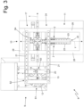
Figure 3 is a plan view of an assembling machine for the preparation of elastomer specimens and created in accordance with this invention; -
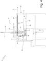
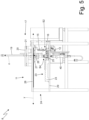
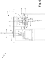
Figures 4 ,5 and6 are respectively a right side view, a left side view and a front view of the assembling machine ofFigure 3 ; and -
Figure 7 is a perspective view, with parts removed for clarity, of a processing station of a mounting unit of the assembling machine ofFigure 3 . - In
Figure 1 , thenumeral 1 denotes in its entirety an elastomer specimen which has a parallelepiped shape and must be subjected to dynamic mechanical-thermal analysis. - As shown in
Figure 2 , thespecimen 1 must be coupled to two sample-holders 2 which engage the two ends of thespecimen 1. Each sample-holder 2 comprises avice 3 which is made to clamp thespecimen 1 and is provided with twojaws specimen 1. In each sample-holder 2 the twojaws vice 3 are crossed and mutually connected by means of a screw 6: by screwing thescrew 6 the twojaws screw 6 the twojaws holder 2, thejaw 4 of thevice 3 is provided with anextension 7 that projects itself from thejaw 4, terminates with a frusto-conical head and is used both to "park" thespecimen 1 assembled with two sample-holders 2 in a warehouse and to mechanically connect the sample-holder 2 to the active members of a measuring machine (known and not shown), which carries out the dynamic mechanical-thermal analysis. - In
Figure 3 ,number 8 denotes as a whole an assembling machine that receives in input thespecimens 1, carries out at least one measurement on each specimen 1 (in particular it measures at least the thickness of each specimen 1), and couples to each specimen 1 a pair of sample-holders 2. - As shown in
Figure 3 , the assemblingmachine 8 comprises ameasuring unit 9 which receives thespecimens 1 from the outside and carries out a measurement of thespecimens 1 themselves, amounting unit 10 which receives thespecimens 1 from themeasuring unit 9 and applies to eachspecimen 1 two corresponding sample-holders 2, and astorage unit 11 which receives thespecimens 1 coupled to the sample-holders 2 from the assemblingunit 10 and stores ("parks") thespecimens 1 themselves until they are collected and analyzed by themeasuring machine 1. - The
measuring unit 9 comprises a wheel (carousel) 12 which is mounted so as to rotate with intermittent motion (i.e. with a stepped motion which cyclically alternates stoppage phases and motion phases) around avertical rotation axis 13. Thewheel 12 presents a plurality of pockets 14 (twenty pockets 14 in the non-limiting embodiment illustrated in the annexed figures), which are oriented radially and are each made to contain acorresponding specimen 1. The rotation of thewheel 12 around theaxis 13 of rotation advances cyclically each pocket 14 through: an input station S1 wherein an operator inserts inside the pocket 14 aspecimen 1, a measuring station S2 wherein the thickness of thespecimen 1 contained in the pocket 14 is measured, and an output station S3 wherein thespecimen 1 is extracted from the pocket 14 and transferred to the assemblingunit 10. - As shown in
Figures 4 and5 , themeasuring unit 9 comprises ameasuring device 15, which is located at the measuring station S2 and comprises at least asensor 16 that measures the thickness of aspecimen 1 in at least three distinct points. - As shown in
Figures 3-6 , themounting unit 10 comprises atransfer device 17 which cyclically collects thespecimens 1 from the pockets 14 of thewheel 12 in the output station S3 and cyclically deposits thespecimens 1 in a processing station S4 of themounting unit 10. Thetransfer device 17 is of the "portal" type and comprises asuction gripping head 18 that is moved (at least) with two degrees of freedom along a vertical direction z and along a longitudinal direction x (arranged horizontally). In particular, thesuction gripping head 18 is carried by an actuating cylinder 19 (for example pneumatic or electric), which is arranged vertically and is made to move thesuction gripping head 18 vertically (i.e. along the vertical direction z); the actuatingcylinder 19 is mounted on aslide 20 which slides (for example due to the action of an electric motor) along tworails 21 parallel to one another which are arranged above thewheel 12 and above the processing station S4. - As illustrated in
Figures 3 ,4 and5 , thestorage unit 11 comprises (at least) arack 22, which comprises twosupports 23 that are parallel to one another and arranged side by side and have respective successions of semicircular recesses made to contain (receive) the cylindrical portions of theextensions 7 of the sample-holders 2. Therack 22 is made to contain both the empty sample-holders 2 (i.e. withoutspecimens 1 and therefore ready to be coupled to the specimens 1) and the full sample-holders 2 (i.e. coupled to the respective specimens 1). - As shown in
Figures 3-7 , themounting unit 10 comprises a (further)transfer device 24, which collects a pair of empty sample-holders 2 (i.e. without specimens 1) from therack 22 of thestorage unit 11 and deposits the pair of empty sample-holders 2 (i.e. without specimens 1) in the processing station S4 of themounting unit 10, wherein the pair of sample-holders 2 is coupled to aspecimen 1; subsequently, thetransfer device 24 collects the pair of full sample-holders 2 (i.e. coupled to a respective specimen 1) from the processing station S4 of themounting unit 10 and deposits the pair of full sample-holders 2 (i.e. coupled to a respective specimen 1) in therack 22 of thestorage unit 11. - The
transfer device 24 is of the "portal" type and comprises a pair ofgrippers 25, which are arranged parallel to each other and spaced apart and each of which is made to grip (and therefore retain with force) the cylindrical portion of anextension 7 of a sample-holder 2; the pair ofgrippers 25 is moved (at least) with two degrees of freedom along the vertical direction z and along a transversal direction Y (arranged horizontally and illustrated inFigures 3-5 ). In particular, the pair ofgrippers 25 is carried by an actuating cylinder 26 (for example pneumatic or electric), which is arranged vertically and is made to move the pair ofgrippers 25 vertically (i.e. along the vertical direction z); the actuatingcylinder 26 is mounted on a pair ofslides 27 which slide (for example due to the action of an electric motor) along two rails 28 (shown inFigure 1 ) parallel to each other which are arranged above therack 22 and above the processing station S4 but lower than therails 21. - As shown in
Figure 7 , the processing station S4 of themounting unit 10 comprises acentral working surface 29 arranged horizontally and on which acentral vise 30 is mounted in a fixed position which is made to receive and tighten aspecimen 4. Thecentral vise 30 includes a fixed jaw 31 (i.e. that does not move), which establishes a reference position, and amovable jaw 32, which is parallel and opposite to the fixedjaw 31 and is movably mounted under the thrust of an actuator 33 (for example a pneumatic or an electric cylinder). In use, theactuator 33 moves themovable jaw 32 away from thefixed jaw 31 to allow thetransfer device 24 to insert aspecimen 1 between the twojaws actuator 33 approaches themovable jaw 32 to thefixed jaw 31 to clamp between the twojaws 31 and 32 a central portion of thespecimen 1 and, at the same time, arrange thespecimen 1 in a given and predetermined position established by thefixed jaw 31. - As shown in
Figure 7 , the processing station S4 of themounting unit 10 includes a pair ofmovable elements 34, which are arranged on the opposite sides of thecentral vice 30 and are mounted on respective rails fixed to theworking surface 29 to slide (translate) only and solely along the longitudinal direction x (i.e. along a straight horizontal direction) under the control of two corresponding actuators 35 (for example pneumatic or electric cylinders); in use, the twomovable elements 34 are moved away or closer together and in a specular manner to thecentral vice 30, which is arranged between the twomovable elements 34 themselves. Eachmovable element 34 supports a supportingplate 36 which is made to receive and accommodate a corresponding sample-holder 2; in particular the supportingplate 36 comprises asemicircular recess 37 made to contain (receive) the frusto-conical portion of theextension 7 of a sample-holder 2 (normally thesemicircular recess 37 negatively reproduces the frusto-conical shape of theextension 7 and therefore also has a frusto-conical shape). In addition, eachmovable element 34 supports apresser 38 which is arranged opposite therecess 37 of the supportingplate 36 and is movable along the longitudinal direction x under the control of an actuator 39 (for example a pneumatic or an electric cylinder). - Finally, the
processing station 10 comprises a motorized screwing device 40 (illustrated inFigures 5 and6 ), which is arranged below the workingsurface 29 and is made to screw/unscrew thescrews 6 of the sample-holders 2 housed in the supportingplates 36 to open or close thevices 6 of the sample-holders 2 themselves. - A description is given below of the operation of the assembling
machine 8 with reference to the processing of asingle specimen 1. - Initially the
specimen 1 is inserted manually by an operator in a pocket 14 of thewheel 12 in the input station S1. - Subsequently the rotation of
wheel 12 around therotation axis 13 moves the pocket 14 carrying thespecimen 1 from the input station S1 to the measuring station S2 wherein thesensor 16 of themeasuring device 15 detect the thickness of thespecimen 1 in at least three distinct zones of thespecimen 1 itself. - Subsequently the rotation of the
wheel 12 around the axis ofrotation 13 moves the pocket 14 carrying thespecimen 1 from the measuring station S2 to the output station S3 wherein thesuction gripping head 18 of thetransfer device 17 collects thespecimen 1 from the pocket 14 of thewheel 12 and transfers thespecimen 1 to the processing station S4 of themounting unit 10; in particular, in the processing station S4, thetransfer device 17 deposits the specimen inside thecentral vice 30 whosejaws central vice 30 has been opened for a smooth entry of the specimen 1). Once thespecimen 1 has been inserted in the central vice 30 (i.e. between the twojaws central vice 30 is closed by the actuator 33 (i.e. themovable jaw 32 of thecentral vice 30 is pushed with a calibrated force toward thefixed jaw 31 to lock thespecimen 1 in a predetermined position). - Simultaneously with the feeding of the
specimen 1 to thecentral vice 30, the twogrippers 25 of thetransfer device 24 collect two empty sample-holders 2 (i.e. without specimens 1) from therack 22 of thestorage unit 11 and deposit the two empty sample-holders 2 onto the supportingplates 36 of themovable elements 34; in this phase the twomovable elements 34 are arranged and maintained (relatively) away from thecentral vise 30 in such a way that the empty sample-holders 2 carried by the supportingplates 36 do not interfere with thespecimen 1 carried by thecentral vice 30. It is important to observe that the empty sample-holders 2 (i.e. without specimens 1) arranged on therack 22 of thestoring unit 11 have theirrespective vices 3 fully open, i.e. thejaws respective vices 3 are distant from one another in such a way as to be ready to receive the ends of aspecimen 1. Once the two sample-holders 2 have been arranged on the supportingplates 36, theactuators 39 push the twopressers 38 against the ends of theprojections 7 of the two sample-holders 2 to push theextensions 7 themselves against therecesses 37 of the supportingplates 36 and then arrange the extensions 7 (therefore the corresponding sample-holders 2) in a given predetermined position established by therecesses 37. - At this point, the
actuators 35 approach the twomovable elements 34 to the central vice 30 (in this phase theactuators 39 maintain thepressers 38 pressed against the ends of theextensions 7 of the two sample-holders 2 to keep the two sample-holders 2 in a given predetermined position established by the recesses 37) in such a way that the two ends of thespecimen 1 carried by thecentral vice 30 enter into thevices 3 of the two sample-holders 2 carried by the supportingplates 36 of the movable elements 34 (i.e. in such a way that thevices 3 of the two sample-holders 2 carried by the supportingplates 36 of themovable elements 34 are arranged around the two ends of thespecimen 1 carried by the central vice 30). Once the approach stroke of themovable elements 34 to thecentral vice 30 has ended (i.e. when themovable elements 34 stops because the two ends of thespecimen 1 carried by thecentral vice 30 are completely inside thevices 3 of the two sample-holders 2 carried by the supportingplates 36 of the movable elements 34), thescrewing device 40 is activated and acts on thescrews 6 of thevices 3 of the two sample-holders 2 carried by the supportingplates 36 of themovable elements 34 in such a way as to close (tighten) with a predetermined clamping force of thevices 3 of the two sample-holders 2 against the ends of thespecimen 1 carried by thecentral vice 30. In this respect it is important to observe that thescrewing device 40 is preferably of the dynamometric type to apply to thevices 3 of the two sample-holders 2 a calibrated and predetermined tightening force. - Subsequently, i.e. once the
vices 3 of the two sample-holders 2 have been tightened against the ends of thespecimen 1 carried by thecentral vice 30,actuators 39 pull away thepressers 38 from theextensions 7 of the two sample-holders 2 carried by the supportingplates 36 and then the twogrippers 25 of thetransfer device 24 collect the two full sample-holders 2 (i.e. coupled to the specimen 1) from the supportingplates 36 of the twomovable elements 34 and deposit the two full sample-holders 2 (i.e. coupled to the specimen 1) on therack 22 of thestorage unit 11. - The assembling
machine 8 described above has many advantages. - Firstly, the assembling
machine 8 described above makes it possible to significantly reduce the time required to prepare thespecimens 1 for a dynamic mechanical-thermal analysis: in the assemblingmachine 8 the time required for the preparation of aspecimen 1 is approximately one minute while a laboratory operator requires on average over four minutes to carry out the same operation (i.e. a quadruple time). - In addition, the assembling
machine 8 described above provides a net improvement in the repeatability of the analysis by eliminating all possible accidental errors which may be committed by a laboratory operator (particularly, but not only, in checking the alignment of thespecimen 1 with respect to the two sample-holders 2 and in controlling the tightening force of thevices 3 of the two sample-holders 2). -
- 1
- specimen
- 2
- sample-holder
- 3
- vice
- 4
- jaw
- 5
- jaw
- 6
- screw
- 7
- extension
- 8
- assembly machine
- 9
- measuring unit
- 10
- mounting unit
- 11
- storage unit
- 12
- wheel
- 13
- rotation axis
- 14
- pockets
- 15
- measuring device
- 16
- sensors
- 17
- transfer device
- 18
- gripping head
- 19
- actuating cylinder
- 20
- slide
- 21
- rails
- 22
- rack
- 23
- supports
- 24
- transfer device
- 25
- grippers
- 26
- actuating cylinder
- 27
- slide
- 28
- rails
- 29
- working surface
- 30
- central vice
- 31
- fixed jaw
- 32
- movable jaw
- 33
- actuator
- 34
- movable elements
- 35
- actuators
- 36
- support plates
- 37
- recess
- 38
- presser
- 39
- actuator
- 40
- screwing device
- S1
- input station
- S2
- measuring station
- S3
- output station
- S4
- processing station
- x
- longitudinal direction
- y
- transverse direction
- z
- vertical direction
Claims (15)
- Assembling machine (8) for coupling the ends of an elastomer specimen (1) to be subjected to dynamic mechanical-thermal analysis to two sample-holders (2), each sample-holder comprising a vice (3) which is made to clamp the specimen (1); the assembling machine (8) characterized in that it comprises:a horizontal working surface (29);a central vice (30) which is mounted in fixed position on the horizontal working surface (29) and is made to engage a central portion of the specimen (1);two movable elements (34), which are mounted on the horizontal working surface (29), are arranged on the opposite sides of the central vice (30), and each carry a supporting plate (36) made to accommodate a corresponding sample-holder (2);a first actuator (35) that is made to translate the two movable elements (34) only and solely along a straight horizontal direction to move in/out the two movable elements (34) from/to the central vice (30); anda powered screwing device (40) which is disposed in the vicinity of the central vice (30) and is made for screwing/unscrewing a screw (6) of the vice (3) of each sample-holder (2) to close the vice (3) itself against an end of the sample (1) carried by the central vice (30).
- Assembling machine (8) according to claim 1, wherein the screwing device (40) is arranged below the horizontal working surface (29).
- Assembling machine (8) according to claim 1 or 2, wherein the central vice (30) comprises a fixed jaw (31) which establishes a reference position and a movable jaw (32) which is parallel and opposite to the fixed jaw (31) and is movably mounted under the thrust of a second actuator (33).
- Assembling machine (8) according to claim 1, 2 or 3, wherein the two movable elements (34) are mounted on respective rails fixed to slide under the control of two corresponding first actuators (35).
- Assembling machine (8) according to one of the claims 1 to 4, wherein each supporting plate (36) comprises a semicircular recess (37) made to contain a frusto-conical portion of an extension (7) of a sample-holder (2).
- Assembling machine (8) according to claim 5, wherein each movable element (34) supports a presser (38) which is arranged in front of the recess (37) of the supporting plate (36) and is movable under the control of a third actuator (39) to push the frusto-conical portion of the extension (7) of a sample-holder (2) against the recess (37) of the supporting plate (36).
- Assembling machine (8) according to one of the claims 1 to 6 and comprising:a storage unit (11) which stores the empty sample-holders (2) and the sample-holders (2) coupled to the specimens (1); anda first transfer device (24) which is made to transfer a pair of empty sample-holders (2) from the storage unit (11) to the two supporting plates (36) and to transfer a pair of sample-holders (2) coupled to a specimen (1) from the two supporting plates (36) to the storage unit (11).
- Assembling machine (8) according to claim 7, wherein the storage unit (11) comprises at least one rack (22), which comprises two supports (23) which are parallel to each other and arranged side by side and have respective successions of semicircular recesses made to contain cylindrical portions of extensions (7) of the sample-holders (2).
- Assembling machine (8) according to claim 7 or 8, wherein the first transfer device (24) comprises a pair of grippers (25), which are arranged parallel to each other and spaced apart and each of which is made to grip a cylindrical portion of an extension (7) of a sample-holder (2).
- Assembling machine (8) according to one of the claims 1 to 9 and comprising:a measuring unit (9) which receives the specimens (1) from the outside and carries out a measurement of the specimens (1) themselves; anda second transfer device (17), which transfers the specimen (1) from the measuring unit (9) to the central vice (30).
- The assembling machine (8) according to claim 10, wherein the measuring unit (9) comprises a wheel (12) which is rotatably mounted so as to rotate with an intermittent motion about a vertical rotation axis (13) and has a plurality of pockets (14), which are orientated radially and are each made to contain a corresponding specimen (1).
- Assembling machine (8) according to claim 11, wherein the rotation of the wheel (12) around the rotation axis (13) advances cyclically each pocket (14) through: an input station (51) wherein a specimen (1) is inserted inside the pocket (14), a measuring station (S2) wherein the thickness of the specimen (1) contained in the pocket (14) is measured, and an output station (S3) wherein the specimen (1) is extracted from the pocket (14) and transferred to the central vice (30) by the second transfer device (17).
- Assembling machine (8) according to claim 12, wherein the measurement unit (9) comprises a measuring device (15), which is arranged in correspondence of the measurement station (S2) and comprises at least one sensor (16) which measures the thickness of a specimen (1) in at least three distinct points.
- Assembly method for coupling the ends of an elastomer specimen (1) to be subjected to dynamic mechanical-thermal analysis to two-sample-holders (2) each sample-holder comprising a vice (3) which is made to clamp the specimen (1); the assembly method characterized in that it comprises the steps of:engaging a central portion of the specimen (1) by means of a central vice (30) mounted in a fixed position on a horizontal working surface (29);having two sample-holders (2) on corresponding supporting plates (36) carried by two movable elements (34), which are mounted on the horizontal working surface (29) and are arranged on opposite sides of the central vice (30);bringing the two movable elements (34) towards the central vice (30) by the action of a first actuator (35) which translates the two movable elements (34) only and solely along a straight horizontal direction; andclosing a vice (3) of each sample-holder (2) against an end of the specimen (1) carried by the central vice (30) using a motorized screwing device (40) which is arranged in the vicinity of the central vice (30) and is made to screw/unscrew a screw (6) of the vice (3) of the sample-holder (2).
- Assembly method according to claim 14, wherein:each supporting plate (36) comprises a semicircular recess (37) made to contain a frusto-conical portion of an extension (7) of a sample-holder (2); andeach movable device (34) supports a presser (38) which is arranged in front of the recess (37) of the supporting plate (36) and is movable under the control of a second actuator (39) to push the frusto-conical portion of the extension (7) of a sample-holder (2) against the recess (37) of the supporting plate (36).
Applications Claiming Priority (2)
| Application Number | Priority Date | Filing Date | Title |
|---|---|---|---|
| IT102018000004705A IT201800004705A1 (en) | 2018-04-19 | 2018-04-19 | ASSEMBLING MACHINE AND ASSEMBLY METHOD FOR COUPLING TWO SAMPLE HOLDERS THE ENDS OF AN ELASTOMER SPECIMEN TO SUBJECT TO DYNAMIC THERMAL-MECHANICAL ANALYSIS |
| PCT/IB2019/053070 WO2019202462A1 (en) | 2018-04-19 | 2019-04-15 | Assembling machine and assembly method for coupling to two sample-holders the ends of an elastomer specimen to be subjected to dynamic mechanical-thermal analysis |
Publications (2)
| Publication Number | Publication Date |
|---|---|
| EP3781925A1 EP3781925A1 (en) | 2021-02-24 |
| EP3781925B1 true EP3781925B1 (en) | 2023-12-06 |
Family
ID=62875232
Family Applications (1)
| Application Number | Title | Priority Date | Filing Date |
|---|---|---|---|
| EP19723872.8A Active EP3781925B1 (en) | 2018-04-19 | 2019-04-15 | Assembling machine and assembly method for coupling to two sample-holders the ends of an elastomer specimen to be subjected to dynamic mechanical-thermal analysis |
Country Status (3)
| Country | Link |
|---|---|
| EP (1) | EP3781925B1 (en) |
| IT (1) | IT201800004705A1 (en) |
| WO (1) | WO2019202462A1 (en) |
Families Citing this family (3)
| Publication number | Priority date | Publication date | Assignee | Title |
|---|---|---|---|---|
| CN111590321A (en) * | 2020-06-30 | 2020-08-28 | 彭敬 | Automatic butt joint assembly equipment for couplings |
| US20240011752A1 (en) * | 2022-07-07 | 2024-01-11 | Illinois Tool Works Inc. | Systems and methods to measure specimen dimensions |
| CN116539453B (en) * | 2023-07-04 | 2023-09-22 | 南通华强布业有限公司 | Elasticity detection device for textile fabric |
Family Cites Families (7)
| Publication number | Priority date | Publication date | Assignee | Title |
|---|---|---|---|---|
| US3885424A (en) * | 1971-12-29 | 1975-05-27 | Uniroyal Inc | Tensile test specimen holder |
| JPS5635043U (en) * | 1979-08-28 | 1981-04-06 | ||
| US4606230A (en) * | 1985-07-08 | 1986-08-19 | The Dow Chemical Company | Tensile test apparatus embodying novel specimen bar magazine |
| US20040055131A1 (en) * | 2002-09-24 | 2004-03-25 | Abid Ghuman | Method of assembling vehicles in a flexible manufacturing system |
| DE102010061742B4 (en) * | 2010-11-22 | 2013-07-04 | Gabo Qualimeter Testanlagen Gmbh | Test device with a sample holder and sample holder for holding a sample |
| FR2977670B1 (en) * | 2011-07-06 | 2014-04-18 | Arts | TENSION AND COMPRESSION TYPE MECHANICAL TEST MICROMACHINE HAVING OPTIMIZED ACCESSIBILITY. |
| CN106226168B (en) * | 2016-08-22 | 2020-03-13 | 中国电力科学研究院 | Automatic bending test device and method based on machine vision |
-
2018
- 2018-04-19 IT IT102018000004705A patent/IT201800004705A1/en unknown
-
2019
- 2019-04-15 WO PCT/IB2019/053070 patent/WO2019202462A1/en not_active Ceased
- 2019-04-15 EP EP19723872.8A patent/EP3781925B1/en active Active
Also Published As
| Publication number | Publication date |
|---|---|
| EP3781925A1 (en) | 2021-02-24 |
| IT201800004705A1 (en) | 2019-10-19 |
| WO2019202462A1 (en) | 2019-10-24 |
Similar Documents
| Publication | Publication Date | Title |
|---|---|---|
| EP3781925B1 (en) | Assembling machine and assembly method for coupling to two sample-holders the ends of an elastomer specimen to be subjected to dynamic mechanical-thermal analysis | |
| US9164113B2 (en) | Methods, systems, and apparatus adapted to transfer sample containers | |
| CN103487315B (en) | A kind of material mechanical performance proving installation | |
| EP1685382B1 (en) | Multiaxial universal testing machine | |
| EP2643677B1 (en) | Testing device with magazine for conducting various kinds of loading tests | |
| CN110018040A (en) | A kind of tiny sample mechanical property high throughput test macro and method | |
| JP7277433B2 (en) | System for analyzing impact and puncture resistance | |
| WO2017217604A1 (en) | Material testing apparatus and material testing method using same | |
| US20200306994A1 (en) | Gripper having a sensor on a transmission member bearing of the gripper | |
| WO2016197431A1 (en) | Dynamometer for car steering wheel position adjustment device | |
| CN105606477A (en) | Fretting wear test device capable of conducting X-ray photoelectron spectroscopy analysis in situ | |
| CZ20003067A3 (en) | Arrangement for fixing, respectively compressing a mechanical retaining means and its use as well as method for controlled and checked setting of the mechanical retaining means | |
| CN117232988A (en) | Tensile testing machine for metal material inspection | |
| CN110987642A (en) | Rigid-flexible composite true triaxial loading device of rubber film outer wrapping loading plate | |
| CN115773873B (en) | A high-precision intelligent valve testing system | |
| CN212008136U (en) | A rigid-flexible composite true triaxial loading device with a rubber film outer loading plate | |
| CN109406653B (en) | Chromatograph with automatic sample adding function | |
| JP7492773B2 (en) | Reclamping device and method for reclamping a workpiece between two clamping devices - Patents.com | |
| CN205404319U (en) | But X ray photoelectron spectroscopic analysis's fine motion wear test equipment is carried out to normal position | |
| CN216117109U (en) | Tensile test system | |
| CN117269388A (en) | Automatic sample injection device and method for gas chromatograph mass spectrometer | |
| EP4544283A1 (en) | Modular material testing apparatus for material testing of a specimen | |
| CN216410470U (en) | Comb resistance test structure | |
| CN223461399U (en) | An electro-hydraulic servo fatigue testing machine | |
| EP2103897A1 (en) | Automatic screw verifier |
Legal Events
| Date | Code | Title | Description |
|---|---|---|---|
| STAA | Information on the status of an ep patent application or granted ep patent |
Free format text: STATUS: UNKNOWN |
|
| STAA | Information on the status of an ep patent application or granted ep patent |
Free format text: STATUS: THE INTERNATIONAL PUBLICATION HAS BEEN MADE |
|
| PUAI | Public reference made under article 153(3) epc to a published international application that has entered the european phase |
Free format text: ORIGINAL CODE: 0009012 |
|
| STAA | Information on the status of an ep patent application or granted ep patent |
Free format text: STATUS: REQUEST FOR EXAMINATION WAS MADE |
|
| 17P | Request for examination filed |
Effective date: 20201118 |
|
| AK | Designated contracting states |
Kind code of ref document: A1 Designated state(s): AL AT BE BG CH CY CZ DE DK EE ES FI FR GB GR HR HU IE IS IT LI LT LU LV MC MK MT NL NO PL PT RO RS SE SI SK SM TR |
|
| AX | Request for extension of the european patent |
Extension state: BA ME |
|
| DAV | Request for validation of the european patent (deleted) | ||
| DAX | Request for extension of the european patent (deleted) | ||
| STAA | Information on the status of an ep patent application or granted ep patent |
Free format text: STATUS: EXAMINATION IS IN PROGRESS |
|
| 17Q | First examination report despatched |
Effective date: 20211124 |
|
| RAP3 | Party data changed (applicant data changed or rights of an application transferred) |
Owner name: BRIDGESTONE EUROPE NV/SA |
|
| REG | Reference to a national code |
Ref country code: DE Ref legal event code: R079 Free format text: PREVIOUS MAIN CLASS: G01N0003040000 Ipc: B23P0019000000 Ref document number: 602019042795 Country of ref document: DE |
|
| GRAP | Despatch of communication of intention to grant a patent |
Free format text: ORIGINAL CODE: EPIDOSNIGR1 |
|
| STAA | Information on the status of an ep patent application or granted ep patent |
Free format text: STATUS: GRANT OF PATENT IS INTENDED |
|
| INTG | Intention to grant announced |
Effective date: 20230630 |
|
| RIC1 | Information provided on ipc code assigned before grant |
Ipc: G01N 35/04 20060101ALN20230619BHEP Ipc: G01N 35/00 20060101ALN20230619BHEP Ipc: G01N 33/44 20060101ALN20230619BHEP Ipc: B23P 19/06 20060101ALN20230619BHEP Ipc: G01N 3/04 20060101ALI20230619BHEP Ipc: B23P 21/00 20060101ALI20230619BHEP Ipc: B23P 19/04 20060101ALI20230619BHEP Ipc: B23P 19/00 20060101AFI20230619BHEP |
|
| GRAS | Grant fee paid |
Free format text: ORIGINAL CODE: EPIDOSNIGR3 |
|
| GRAA | (expected) grant |
Free format text: ORIGINAL CODE: 0009210 |
|
| STAA | Information on the status of an ep patent application or granted ep patent |
Free format text: STATUS: THE PATENT HAS BEEN GRANTED |
|
| AK | Designated contracting states |
Kind code of ref document: B1 Designated state(s): AL AT BE BG CH CY CZ DE DK EE ES FI FR GB GR HR HU IE IS IT LI LT LU LV MC MK MT NL NO PL PT RO RS SE SI SK SM TR |
|
| REG | Reference to a national code |
Ref country code: GB Ref legal event code: FG4D |
|
| REG | Reference to a national code |
Ref country code: CH Ref legal event code: EP |
|
| REG | Reference to a national code |
Ref country code: DE Ref legal event code: R096 Ref document number: 602019042795 Country of ref document: DE |
|
| REG | Reference to a national code |
Ref country code: IE Ref legal event code: FG4D |
|
| REG | Reference to a national code |
Ref country code: LT Ref legal event code: MG9D |
|
| P01 | Opt-out of the competence of the unified patent court (upc) registered |
Effective date: 20240219 |
|
| PG25 | Lapsed in a contracting state [announced via postgrant information from national office to epo] |
Ref country code: GR Free format text: LAPSE BECAUSE OF FAILURE TO SUBMIT A TRANSLATION OF THE DESCRIPTION OR TO PAY THE FEE WITHIN THE PRESCRIBED TIME-LIMIT Effective date: 20240307 |
|
| REG | Reference to a national code |
Ref country code: NL Ref legal event code: MP Effective date: 20231206 |
|
| PG25 | Lapsed in a contracting state [announced via postgrant information from national office to epo] |
Ref country code: LT Free format text: LAPSE BECAUSE OF FAILURE TO SUBMIT A TRANSLATION OF THE DESCRIPTION OR TO PAY THE FEE WITHIN THE PRESCRIBED TIME-LIMIT Effective date: 20231206 |
|
| PG25 | Lapsed in a contracting state [announced via postgrant information from national office to epo] |
Ref country code: ES Free format text: LAPSE BECAUSE OF FAILURE TO SUBMIT A TRANSLATION OF THE DESCRIPTION OR TO PAY THE FEE WITHIN THE PRESCRIBED TIME-LIMIT Effective date: 20231206 |
|
| PG25 | Lapsed in a contracting state [announced via postgrant information from national office to epo] |
Ref country code: LT Free format text: LAPSE BECAUSE OF FAILURE TO SUBMIT A TRANSLATION OF THE DESCRIPTION OR TO PAY THE FEE WITHIN THE PRESCRIBED TIME-LIMIT Effective date: 20231206 Ref country code: GR Free format text: LAPSE BECAUSE OF FAILURE TO SUBMIT A TRANSLATION OF THE DESCRIPTION OR TO PAY THE FEE WITHIN THE PRESCRIBED TIME-LIMIT Effective date: 20240307 Ref country code: ES Free format text: LAPSE BECAUSE OF FAILURE TO SUBMIT A TRANSLATION OF THE DESCRIPTION OR TO PAY THE FEE WITHIN THE PRESCRIBED TIME-LIMIT Effective date: 20231206 Ref country code: BG Free format text: LAPSE BECAUSE OF FAILURE TO SUBMIT A TRANSLATION OF THE DESCRIPTION OR TO PAY THE FEE WITHIN THE PRESCRIBED TIME-LIMIT Effective date: 20240306 |
|
| REG | Reference to a national code |
Ref country code: AT Ref legal event code: MK05 Ref document number: 1637953 Country of ref document: AT Kind code of ref document: T Effective date: 20231206 |
|
| PG25 | Lapsed in a contracting state [announced via postgrant information from national office to epo] |
Ref country code: NL Free format text: LAPSE BECAUSE OF FAILURE TO SUBMIT A TRANSLATION OF THE DESCRIPTION OR TO PAY THE FEE WITHIN THE PRESCRIBED TIME-LIMIT Effective date: 20231206 |
|
| PG25 | Lapsed in a contracting state [announced via postgrant information from national office to epo] |
Ref country code: SE Free format text: LAPSE BECAUSE OF FAILURE TO SUBMIT A TRANSLATION OF THE DESCRIPTION OR TO PAY THE FEE WITHIN THE PRESCRIBED TIME-LIMIT Effective date: 20231206 Ref country code: RS Free format text: LAPSE BECAUSE OF FAILURE TO SUBMIT A TRANSLATION OF THE DESCRIPTION OR TO PAY THE FEE WITHIN THE PRESCRIBED TIME-LIMIT Effective date: 20231206 Ref country code: NO Free format text: LAPSE BECAUSE OF FAILURE TO SUBMIT A TRANSLATION OF THE DESCRIPTION OR TO PAY THE FEE WITHIN THE PRESCRIBED TIME-LIMIT Effective date: 20240306 Ref country code: NL Free format text: LAPSE BECAUSE OF FAILURE TO SUBMIT A TRANSLATION OF THE DESCRIPTION OR TO PAY THE FEE WITHIN THE PRESCRIBED TIME-LIMIT Effective date: 20231206 Ref country code: LV Free format text: LAPSE BECAUSE OF FAILURE TO SUBMIT A TRANSLATION OF THE DESCRIPTION OR TO PAY THE FEE WITHIN THE PRESCRIBED TIME-LIMIT Effective date: 20231206 Ref country code: HR Free format text: LAPSE BECAUSE OF FAILURE TO SUBMIT A TRANSLATION OF THE DESCRIPTION OR TO PAY THE FEE WITHIN THE PRESCRIBED TIME-LIMIT Effective date: 20231206 |
|
| PG25 | Lapsed in a contracting state [announced via postgrant information from national office to epo] |
Ref country code: IS Free format text: LAPSE BECAUSE OF FAILURE TO SUBMIT A TRANSLATION OF THE DESCRIPTION OR TO PAY THE FEE WITHIN THE PRESCRIBED TIME-LIMIT Effective date: 20240406 |
|
| PG25 | Lapsed in a contracting state [announced via postgrant information from national office to epo] |
Ref country code: AT Free format text: LAPSE BECAUSE OF FAILURE TO SUBMIT A TRANSLATION OF THE DESCRIPTION OR TO PAY THE FEE WITHIN THE PRESCRIBED TIME-LIMIT Effective date: 20231206 Ref country code: CZ Free format text: LAPSE BECAUSE OF FAILURE TO SUBMIT A TRANSLATION OF THE DESCRIPTION OR TO PAY THE FEE WITHIN THE PRESCRIBED TIME-LIMIT Effective date: 20231206 |
|
| PG25 | Lapsed in a contracting state [announced via postgrant information from national office to epo] |
Ref country code: SK Free format text: LAPSE BECAUSE OF FAILURE TO SUBMIT A TRANSLATION OF THE DESCRIPTION OR TO PAY THE FEE WITHIN THE PRESCRIBED TIME-LIMIT Effective date: 20231206 |
|
| PG25 | Lapsed in a contracting state [announced via postgrant information from national office to epo] |
Ref country code: SM Free format text: LAPSE BECAUSE OF FAILURE TO SUBMIT A TRANSLATION OF THE DESCRIPTION OR TO PAY THE FEE WITHIN THE PRESCRIBED TIME-LIMIT Effective date: 20231206 Ref country code: SK Free format text: LAPSE BECAUSE OF FAILURE TO SUBMIT A TRANSLATION OF THE DESCRIPTION OR TO PAY THE FEE WITHIN THE PRESCRIBED TIME-LIMIT Effective date: 20231206 Ref country code: RO Free format text: LAPSE BECAUSE OF FAILURE TO SUBMIT A TRANSLATION OF THE DESCRIPTION OR TO PAY THE FEE WITHIN THE PRESCRIBED TIME-LIMIT Effective date: 20231206 Ref country code: IT Free format text: LAPSE BECAUSE OF FAILURE TO SUBMIT A TRANSLATION OF THE DESCRIPTION OR TO PAY THE FEE WITHIN THE PRESCRIBED TIME-LIMIT Effective date: 20231206 Ref country code: IS Free format text: LAPSE BECAUSE OF FAILURE TO SUBMIT A TRANSLATION OF THE DESCRIPTION OR TO PAY THE FEE WITHIN THE PRESCRIBED TIME-LIMIT Effective date: 20240406 Ref country code: EE Free format text: LAPSE BECAUSE OF FAILURE TO SUBMIT A TRANSLATION OF THE DESCRIPTION OR TO PAY THE FEE WITHIN THE PRESCRIBED TIME-LIMIT Effective date: 20231206 Ref country code: CZ Free format text: LAPSE BECAUSE OF FAILURE TO SUBMIT A TRANSLATION OF THE DESCRIPTION OR TO PAY THE FEE WITHIN THE PRESCRIBED TIME-LIMIT Effective date: 20231206 Ref country code: AT Free format text: LAPSE BECAUSE OF FAILURE TO SUBMIT A TRANSLATION OF THE DESCRIPTION OR TO PAY THE FEE WITHIN THE PRESCRIBED TIME-LIMIT Effective date: 20231206 |
|
| PG25 | Lapsed in a contracting state [announced via postgrant information from national office to epo] |
Ref country code: PT Free format text: LAPSE BECAUSE OF FAILURE TO SUBMIT A TRANSLATION OF THE DESCRIPTION OR TO PAY THE FEE WITHIN THE PRESCRIBED TIME-LIMIT Effective date: 20240408 Ref country code: PL Free format text: LAPSE BECAUSE OF FAILURE TO SUBMIT A TRANSLATION OF THE DESCRIPTION OR TO PAY THE FEE WITHIN THE PRESCRIBED TIME-LIMIT Effective date: 20231206 |
|
| PG25 | Lapsed in a contracting state [announced via postgrant information from national office to epo] |
Ref country code: PT Free format text: LAPSE BECAUSE OF FAILURE TO SUBMIT A TRANSLATION OF THE DESCRIPTION OR TO PAY THE FEE WITHIN THE PRESCRIBED TIME-LIMIT Effective date: 20240408 Ref country code: PL Free format text: LAPSE BECAUSE OF FAILURE TO SUBMIT A TRANSLATION OF THE DESCRIPTION OR TO PAY THE FEE WITHIN THE PRESCRIBED TIME-LIMIT Effective date: 20231206 |
|
| REG | Reference to a national code |
Ref country code: DE Ref legal event code: R097 Ref document number: 602019042795 Country of ref document: DE |
|
| PG25 | Lapsed in a contracting state [announced via postgrant information from national office to epo] |
Ref country code: DK Free format text: LAPSE BECAUSE OF FAILURE TO SUBMIT A TRANSLATION OF THE DESCRIPTION OR TO PAY THE FEE WITHIN THE PRESCRIBED TIME-LIMIT Effective date: 20231206 |
|
| PLBE | No opposition filed within time limit |
Free format text: ORIGINAL CODE: 0009261 |
|
| STAA | Information on the status of an ep patent application or granted ep patent |
Free format text: STATUS: NO OPPOSITION FILED WITHIN TIME LIMIT |
|
| PG25 | Lapsed in a contracting state [announced via postgrant information from national office to epo] |
Ref country code: SI Free format text: LAPSE BECAUSE OF FAILURE TO SUBMIT A TRANSLATION OF THE DESCRIPTION OR TO PAY THE FEE WITHIN THE PRESCRIBED TIME-LIMIT Effective date: 20231206 |
|
| PG25 | Lapsed in a contracting state [announced via postgrant information from national office to epo] |
Ref country code: SI Free format text: LAPSE BECAUSE OF FAILURE TO SUBMIT A TRANSLATION OF THE DESCRIPTION OR TO PAY THE FEE WITHIN THE PRESCRIBED TIME-LIMIT Effective date: 20231206 Ref country code: DK Free format text: LAPSE BECAUSE OF FAILURE TO SUBMIT A TRANSLATION OF THE DESCRIPTION OR TO PAY THE FEE WITHIN THE PRESCRIBED TIME-LIMIT Effective date: 20231206 |
|
| 26N | No opposition filed |
Effective date: 20240909 |
|
| PG25 | Lapsed in a contracting state [announced via postgrant information from national office to epo] |
Ref country code: MC Free format text: LAPSE BECAUSE OF FAILURE TO SUBMIT A TRANSLATION OF THE DESCRIPTION OR TO PAY THE FEE WITHIN THE PRESCRIBED TIME-LIMIT Effective date: 20231206 |
|
| PG25 | Lapsed in a contracting state [announced via postgrant information from national office to epo] |
Ref country code: MC Free format text: LAPSE BECAUSE OF FAILURE TO SUBMIT A TRANSLATION OF THE DESCRIPTION OR TO PAY THE FEE WITHIN THE PRESCRIBED TIME-LIMIT Effective date: 20231206 |
|
| REG | Reference to a national code |
Ref country code: CH Ref legal event code: PL |
|
| GBPC | Gb: european patent ceased through non-payment of renewal fee |
Effective date: 20240415 |
|
| REG | Reference to a national code |
Ref country code: BE Ref legal event code: MM Effective date: 20240430 |
|
| PG25 | Lapsed in a contracting state [announced via postgrant information from national office to epo] |
Ref country code: BE Free format text: LAPSE BECAUSE OF NON-PAYMENT OF DUE FEES Effective date: 20240430 |
|
| PG25 | Lapsed in a contracting state [announced via postgrant information from national office to epo] |
Ref country code: GB Free format text: LAPSE BECAUSE OF NON-PAYMENT OF DUE FEES Effective date: 20240415 |
|
| PG25 | Lapsed in a contracting state [announced via postgrant information from national office to epo] |
Ref country code: GB Free format text: LAPSE BECAUSE OF NON-PAYMENT OF DUE FEES Effective date: 20240415 Ref country code: BE Free format text: LAPSE BECAUSE OF NON-PAYMENT OF DUE FEES Effective date: 20240430 Ref country code: CH Free format text: LAPSE BECAUSE OF NON-PAYMENT OF DUE FEES Effective date: 20240430 |
|
| PG25 | Lapsed in a contracting state [announced via postgrant information from national office to epo] |
Ref country code: IE Free format text: LAPSE BECAUSE OF NON-PAYMENT OF DUE FEES Effective date: 20240415 |
|
| PGFP | Annual fee paid to national office [announced via postgrant information from national office to epo] |
Ref country code: DE Payment date: 20250319 Year of fee payment: 7 |
|
| PG25 | Lapsed in a contracting state [announced via postgrant information from national office to epo] |
Ref country code: CY Free format text: LAPSE BECAUSE OF FAILURE TO SUBMIT A TRANSLATION OF THE DESCRIPTION OR TO PAY THE FEE WITHIN THE PRESCRIBED TIME-LIMIT; INVALID AB INITIO Effective date: 20190415 |
|
| PG25 | Lapsed in a contracting state [announced via postgrant information from national office to epo] |
Ref country code: HU Free format text: LAPSE BECAUSE OF FAILURE TO SUBMIT A TRANSLATION OF THE DESCRIPTION OR TO PAY THE FEE WITHIN THE PRESCRIBED TIME-LIMIT; INVALID AB INITIO Effective date: 20190415 |
|
| PG25 | Lapsed in a contracting state [announced via postgrant information from national office to epo] |
Ref country code: FI Free format text: LAPSE BECAUSE OF FAILURE TO SUBMIT A TRANSLATION OF THE DESCRIPTION OR TO PAY THE FEE WITHIN THE PRESCRIBED TIME-LIMIT Effective date: 20231207 |
|
| PGFP | Annual fee paid to national office [announced via postgrant information from national office to epo] |
Ref country code: LU Payment date: 20260319 Year of fee payment: 8 |
|
| PGFP | Annual fee paid to national office [announced via postgrant information from national office to epo] |
Ref country code: FR Payment date: 20260320 Year of fee payment: 8 |