EP3781901B1 - Dynamically adapting operation of a coordinate measuring machine - Google Patents
Dynamically adapting operation of a coordinate measuring machine Download PDFInfo
- Publication number
- EP3781901B1 EP3781901B1 EP19718027.6A EP19718027A EP3781901B1 EP 3781901 B1 EP3781901 B1 EP 3781901B1 EP 19718027 A EP19718027 A EP 19718027A EP 3781901 B1 EP3781901 B1 EP 3781901B1
- Authority
- EP
- European Patent Office
- Prior art keywords
- target points
- trajectory
- work piece
- remainder
- established
- Prior art date
- Legal status (The legal status is an assumption and is not a legal conclusion. Google has not performed a legal analysis and makes no representation as to the accuracy of the status listed.)
- Active
Links
- 238000005259 measurement Methods 0.000 claims description 184
- 239000000523 sample Substances 0.000 claims description 48
- 238000000034 method Methods 0.000 claims description 35
- 230000001052 transient effect Effects 0.000 claims description 11
- 238000004458 analytical method Methods 0.000 claims description 8
- 238000004891 communication Methods 0.000 claims description 7
- 238000012545 processing Methods 0.000 claims description 2
- 230000033001 locomotion Effects 0.000 description 13
- 230000008569 process Effects 0.000 description 8
- 238000006073 displacement reaction Methods 0.000 description 4
- 150000001875 compounds Chemical class 0.000 description 3
- 238000004590 computer program Methods 0.000 description 3
- 230000003287 optical effect Effects 0.000 description 3
- 230000009471 action Effects 0.000 description 2
- 230000009286 beneficial effect Effects 0.000 description 2
- 230000008901 benefit Effects 0.000 description 2
- 230000008859 change Effects 0.000 description 2
- 238000012512 characterization method Methods 0.000 description 2
- 238000005516 engineering process Methods 0.000 description 2
- 230000005540 biological transmission Effects 0.000 description 1
- 238000011960 computer-aided design Methods 0.000 description 1
- 230000000694 effects Effects 0.000 description 1
- 238000011156 evaluation Methods 0.000 description 1
- 230000006870 function Effects 0.000 description 1
- 230000006872 improvement Effects 0.000 description 1
- 238000004519 manufacturing process Methods 0.000 description 1
- 238000012986 modification Methods 0.000 description 1
- 230000004048 modification Effects 0.000 description 1
- 239000004065 semiconductor Substances 0.000 description 1
- 238000004441 surface measurement Methods 0.000 description 1
Images


Classifications
-
- G—PHYSICS
- G01—MEASURING; TESTING
- G01B—MEASURING LENGTH, THICKNESS OR SIMILAR LINEAR DIMENSIONS; MEASURING ANGLES; MEASURING AREAS; MEASURING IRREGULARITIES OF SURFACES OR CONTOURS
- G01B5/00—Measuring arrangements characterised by the use of mechanical techniques
- G01B5/004—Measuring arrangements characterised by the use of mechanical techniques for measuring coordinates of points
- G01B5/008—Measuring arrangements characterised by the use of mechanical techniques for measuring coordinates of points using coordinate measuring machines
-
- G—PHYSICS
- G01—MEASURING; TESTING
- G01B—MEASURING LENGTH, THICKNESS OR SIMILAR LINEAR DIMENSIONS; MEASURING ANGLES; MEASURING AREAS; MEASURING IRREGULARITIES OF SURFACES OR CONTOURS
- G01B21/00—Measuring arrangements or details thereof, where the measuring technique is not covered by the other groups of this subclass, unspecified or not relevant
- G01B21/02—Measuring arrangements or details thereof, where the measuring technique is not covered by the other groups of this subclass, unspecified or not relevant for measuring length, width, or thickness
- G01B21/04—Measuring arrangements or details thereof, where the measuring technique is not covered by the other groups of this subclass, unspecified or not relevant for measuring length, width, or thickness by measuring coordinates of points
- G01B21/047—Accessories, e.g. for positioning, for tool-setting, for measuring probes
-
- G—PHYSICS
- G01—MEASURING; TESTING
- G01B—MEASURING LENGTH, THICKNESS OR SIMILAR LINEAR DIMENSIONS; MEASURING ANGLES; MEASURING AREAS; MEASURING IRREGULARITIES OF SURFACES OR CONTOURS
- G01B21/00—Measuring arrangements or details thereof, where the measuring technique is not covered by the other groups of this subclass, unspecified or not relevant
- G01B21/02—Measuring arrangements or details thereof, where the measuring technique is not covered by the other groups of this subclass, unspecified or not relevant for measuring length, width, or thickness
- G01B21/04—Measuring arrangements or details thereof, where the measuring technique is not covered by the other groups of this subclass, unspecified or not relevant for measuring length, width, or thickness by measuring coordinates of points
- G01B21/045—Correction of measurements
-
- G—PHYSICS
- G01—MEASURING; TESTING
- G01B—MEASURING LENGTH, THICKNESS OR SIMILAR LINEAR DIMENSIONS; MEASURING ANGLES; MEASURING AREAS; MEASURING IRREGULARITIES OF SURFACES OR CONTOURS
- G01B5/00—Measuring arrangements characterised by the use of mechanical techniques
- G01B5/20—Measuring arrangements characterised by the use of mechanical techniques for measuring contours or curvatures
-
- G—PHYSICS
- G05—CONTROLLING; REGULATING
- G05B—CONTROL OR REGULATING SYSTEMS IN GENERAL; FUNCTIONAL ELEMENTS OF SUCH SYSTEMS; MONITORING OR TESTING ARRANGEMENTS FOR SUCH SYSTEMS OR ELEMENTS
- G05B19/00—Programme-control systems
- G05B19/02—Programme-control systems electric
- G05B19/18—Numerical control [NC], i.e. automatically operating machines, in particular machine tools, e.g. in a manufacturing environment, so as to execute positioning, movement or co-ordinated operations by means of programme data in numerical form
- G05B19/401—Numerical control [NC], i.e. automatically operating machines, in particular machine tools, e.g. in a manufacturing environment, so as to execute positioning, movement or co-ordinated operations by means of programme data in numerical form characterised by control arrangements for measuring, e.g. calibration and initialisation, measuring workpiece for machining purposes
-
- G—PHYSICS
- G05—CONTROLLING; REGULATING
- G05B—CONTROL OR REGULATING SYSTEMS IN GENERAL; FUNCTIONAL ELEMENTS OF SUCH SYSTEMS; MONITORING OR TESTING ARRANGEMENTS FOR SUCH SYSTEMS OR ELEMENTS
- G05B2219/00—Program-control systems
- G05B2219/30—Nc systems
- G05B2219/37—Measurements
- G05B2219/37218—Compensate for offset due to probe diameter, detect exact contact point
-
- G—PHYSICS
- G05—CONTROLLING; REGULATING
- G05B—CONTROL OR REGULATING SYSTEMS IN GENERAL; FUNCTIONAL ELEMENTS OF SUCH SYSTEMS; MONITORING OR TESTING ARRANGEMENTS FOR SUCH SYSTEMS OR ELEMENTS
- G05B2219/00—Program-control systems
- G05B2219/30—Nc systems
- G05B2219/37—Measurements
- G05B2219/37452—Generate nc program from metrology program, defining cmm probe path
Landscapes
- Physics & Mathematics (AREA)
- General Physics & Mathematics (AREA)
- Engineering & Computer Science (AREA)
- Human Computer Interaction (AREA)
- Manufacturing & Machinery (AREA)
- Automation & Control Theory (AREA)
- A Measuring Device Byusing Mechanical Method (AREA)
- Length Measuring Devices With Unspecified Measuring Means (AREA)
Description
- The present invention relates to coordinate measuring machines, and more particularly to operation of coordinate measuring machines.
- Coordinate measuring machines (CMMs) are used for accurately measuring a wide variety of work pieces. For example, CMMs can measure critical dimensions of aircraft engine components, surgical tools, and gun barrels. Precise and accurate measurements help ensure that their underlying systems, such as an aircraft in the case of aircraft components, operate as specified.
- In operation, some coordinate measuring machines blindly execute a sequence of moves and measurements, on the assumption that the work piece is in an expected, or specified, orientation relative to the coordinate measuring machine. In the work piece is not in that orientation, however, the moves and measurements may fail to properly measure the work piece, or may even contact the work piece in undesirable, unintended ways, risking damage to the work piece or the coordinate measuring machine itself.
- Of the prior art,
US 2016/0341533 A1 discloses a method for controlling a shape measuring apparatus,WO 2018/060693 A1 discloses a method and apparatus for measuring an object andUS 2005/0263727 A1 discloses a surface scan measuring device, method, program and recording medium. - In accordance with one embodiment described below, a system for measuring a work piece includes a trajectory module configured to store an established measurement trajectory, and a controller in data communication with the trajectory module to receive, from the trajectory module, the established measurement trajectory. The controller is configured to control a measuring probe to measure the work piece according to a subset of, but less than all of, the established measurement trajectory.
- The system also includes a trajectory analysis module configured to analyze an actual trajectory executed by the measuring probe, relative to the established measurement trajectory, based on measurements of the work piece taken according to at least two consecutive target points of the established measurement trajectory, and to produce a trajectory divergence.
- The system also includes a trajectory revision module configured to generate a revised trajectory for acquiring a remainder of the measurements based on the established measurement trajectory and the trajectory divergence. The controller is also configured to control the measuring probe to continue measuring the work piece according to the revised trajectory.
- For example, in some embodiments, the established measurement trajectory includes a plurality of target points, the plurality of target points having a fixed spatial relationship relative to one another; and generating a revised trajectory includes retaining the fixed spatial relationship of the measurements relative to one another. Moreover, in some embodiments, the established measurement trajectory further includes a plurality of moves corresponding to the plurality of target points, each move defining a path, followed by a probe of the coordinate measuring machine, between consecutive target points.
- In some embodiments, generating a revised trajectory includes one or both of (i) shifting a subset of target points of the established measurement trajectory by linearly offsetting the subset of target points in space to match a linear offset of the work piece and/or (ii) shifting a subset of target points of the established measurement trajectory by rotationally offsetting the subset of target points in space to match a rotational offset of the work piece.
- In some embodiments, the established measurement trajectory further includes a plurality of moves corresponding to the plurality of target points, each move of the plurality of moves defining a path, followed by the measuring probe, between consecutive target points, the plurality of moves having a fixed spatial relationship relative to one another. In such embodiments, generating a revised trajectory includes retaining the fixed spatial relationship of the moves relative to one another.
- Another embodiment is a method of dynamically adapting the operation of a coordinate measuring machine while measuring a work piece. The method includes providing, to the coordinate measuring machine, an established measurement trajectory including a plurality of pre-defined target points, each of the plurality of pre-defined target points having a coordinate location; controlling the coordinate measuring machine to acquire a plurality of initial acquired measurements of the work piece according to an initial set of target points, the initial set of target points being a subset of the plurality of pre-defined target points, the initial set of pre-defined target points defining a remainder of target points; and storing the plurality of initial acquired measurements in a memory.
- The method also includes controlling the coordinate measuring machine to acquire the plurality of initial acquired measurements , but - prior to completing execution of the established measurement trajectory - establishing a trajectory divergence based on at least two of the plurality of initial acquired measurements. Based on the trajectory divergence, the method produces a re-oriented set of target points from the remainder of target points, the re-oriented set of target points configured to reduce the trajectory divergence.
- Thereafter, the method controls the coordinate measuring machine to continue measuring the work piece according to the re-oriented set of target points, thereby acquiring a remainder of measurements; and stores the remainder of measurements in the memory.
- In some embodiments, the pre-defined target points of the established measurement trajectory have a fixed spatial relationship relative to one another; and producing a re-oriented set of target points includes shifting the remainder of target points in space, but retaining the fixed spatial relationship of the remainder of target points relative to one another.
- In some embodiments, the established measurement trajectory further includes a plurality of moves corresponding to the plurality of pre-defined target points, each move of the plurality of moves defining a path, followed by a probe of the coordinate measuring machine, between consecutive ones of the pre-defined target points, and producing a re-oriented set of target points includes shifting the remainder of target points in space, but retaining the fixed spatial relationship of the moves relative to one another.
- In some embodiments, shifting the remainder of target points in space includes one or both of (i) linearly offsetting each of the remainder of target points in space to match a linear offset of the work piece, and/or (ii) rotationally offsetting the remainder of target points in space to match a rotational offset of the work piece.
- Yet another embodiment is a non-transient computer programmed product bearing non-transient executable computer code which, when executed by a computer processor, control a coordinate measuring machine. The executable computer code includes code for causing a controller to measure a location on the work piece of each of two target points, each of the two target points having a pre-established coordinate location according to an established measurement trajectory, to produce two corresponding location measurements, the two target points defining a remainder of target points of the established measurement trajectory; code for assessing, prior to completing execution of the established measurement trajectory, an orientation of the work piece by processing the two location measurements relative to the pre-established coordinate locations; code for producing a re-oriented set of target points from the remainder of target points of the established measurement trajectory; and code for controlling the coordinate measuring machine to continue measuring the work piece by measuring the work piece according to the re-oriented set of target points.
- In some embodiments, the established measurement trajectory includes a plurality of target points, the plurality of target points having a fixed spatial relationship relative to one another; and the code for producing a re-oriented set of target points includes code for shifting the remainder of target points in space, but retaining the fixed spatial relationship of the remainder of target points relative to one another.
- In some embodiments, the established measurement trajectory further includes a plurality of moves corresponding to the plurality of target points, each move defining a path, followed by a probe of the coordinate measuring machine, between consecutive target points. In some embodiments, target points, the plurality of moves have a fixed spatial relationship relative to one another, and the code for producing a re-oriented set of target points includes code for shifting the remainder of target points in space, but retaining the fixed spatial relationship of the remainder of target points relative to one another.
- In some embodiments, the code for shifting the remainder of target points in space includes code for one or both of (i) offsetting the remainder of target points in space to match a linear offset of the work piece, and/or (ii) offsetting the remainder of target points in space to match a rotational offset of the work piece.
- The invention is defined in the appended claims.
- The foregoing features of embodiments will be more readily understood by reference to the following detailed description, taken with reference to the accompanying drawings, in which:
-
Fig. 1A and Fig. 1B schematically illustrate an embodiment of a CMM; -
Fig. 2A schematically illustrates a probe measuring a work piece; -
Fig. 2B schematically illustrates a probe measuring a mis-oriented work piece; -
Fig. 2C schematically illustrates a trajectory delta; -
Fig. 2D schematically illustrates a shift ofpoint 235 to a revised location; -
Fig. 2E schematically illustrates a hybrid trajectory; -
Fig. 2F schematically illustrates a probe measuring a mis-oriented work piece; -
Fig. 2G schematically illustrates a trajectory delta; -
Figs. 2H-2L schematically illustrate another embodiment of a mis-oriented work piece and a trajectory delta; -
Fig. 2M schematically illustrates a pre-established trajectory and an actual trajectory of awork piece 200 that is both rotationally offset and laterally offset; -
Fig. 3 is a flow chart of a method of dynamically adapting a trajectory; -
Fig. 4 schematically illustrates a system for dynamically adapting operation of a coordinate measuring machine. - Various embodiments described herein improve the operation of a coordinate measuring machine by revising its measurement trajectory, after beginning but prior to completing its measurement of a work piece, upon detecting misalignment between its original measurement trajectory and the contours of the work piece. The coordinate measuring machine then completes its measurement of the work piece using the revised trajectory. This is an improvement over previous coordinate measuring machine operation because it allows the coordinate measuring machine to complete its measurement of a work piece without having to re-start the measurement process, or develop a new trajectory. Moreover, re-using portions of the pre-established measurement trajectory in a revised trajectory can be beneficial, for example, where the pre-established measurement trajectory has been tailored or optimized for efficiency, or specified to avoid accidental or other undesired contact with the work piece.
-
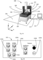
Fig. 1A shows one type of coordinate measurement machine 100 (hereinafter "CMM 100") that may be configured in accordance with illustrative embodiments. As known by those in the art, theCMM 100, which is supported on afloor 101 in this figure, measures an object orwork piece 200 on its bed/table/base (referred to as "base 102"). Generally, the base 102 of theCMM 100 defines anX-Y plane 110 that typically is parallel to the plane of thefloor 101, and ameasurement volume 111 in the X-Y-Z space above theX-Y plane 110. - To measure an object within a measuring
volume 111 on its base 102, theCMM 100 hasmovable features 122 arranged to move ameasuring device 103, such as aprobe 105 coupled with a movable arm 104 (Fig. 2A ). Alternatively, some embodiments move the base 102 (e.g., or a portion of the base 102, such as a moveable table 107) with respect to astationary measuring device 103. Either way, themovable features 122 of theCMM 100 manipulate the relative positions of the measuringdevice 103 and the object with respect to one another to obtain the desired measurement. Accordingly, theCMM 100 can measure the location of a variety of features of the object or artifact. - The
CMM 100 has a motion and data control system 120 (or "controller" or "control logic") that controls and coordinates its movements and activities. Among other things, thecontrol system 120 includes acomputer processor 121 and the noted sensors/movable features 122. Thecomputer processor 121, which may include a microprocessor, may have on-board digital memory (e.g., RAM or ROM) for storing data and/or computer code, including instructions for implementing some or all of the control system operations and methods. Alternatively, or in addition, thecomputer processor 121 may be operably coupled to other digital memory, such as RAM or ROM, or a programmable memory circuit for storing such computer code and/or control data. - Alternatively, or in addition, some embodiments couple the
CMM 100 with an external computer (or "host computer") 130. In a manner similar to thecontrol system 120, thehost computer 130 has a computer processor such as those described above, and computer memory in communication with the processor of theCMM 100. The memory is configured to hold non-transient computer instructions capable of being executed by the processor, and/or to store non-transient data, such as data acquired as a result of the measurements of an object on the base 102. - Among other things, the
host computer 130 may be a desktop computer, a tower computer, or a laptop computer, such as those available from Dell Inc., or even a tablet computer, such as the iPad™ available from Apple Inc. Thehost computer 130 may be coupled to theCMM 100 via a hardwired connection, such as anEthernet cable 131, or via a wireless link, such as a Bluetooth link or a Wi-Fi link. Thehost computer 130 may, for example, include software to control theCMM 100 during use or calibration, and/or may include software configured to process data acquired during operation of theCMM 100. In addition, thehost computer 130 may include a user interface configured to allow a user to manually operate theCMM 100. - Because their relative positions are determined by the action of the
movable features 122, theCMM 100 may be considered as having knowledge of the relative locations of the base 102, and the object or artifact, with respect to itsmeasuring device 103. More particularly, thecomputer processor 121 and/orcomputer 130 control and store information about the motions of the movable features 122. Alternatively, or in addition, themovable features 122 of some embodiments include sensors that sense the locations of the table 107 and/or measuringdevice 103, and report that data to thecomputers device 103 of theCMM 100 may be recorded in terms of a one-dimensional (e.g., X; Y; or Z); two-dimensional (e.g., X-Y; X-Z; Y-Z) or three-dimensional (X-Y-Z) coordinate system referenced to a point on theCMM 100. - Some CMMs also include a
manual user interface 125, such as that shown generically inFig. 1A and as further schematically illustrated inFig. 1B . As shown, themanual user interface 125 may have control buttons 125A and knobs 125B that allow a user to manually operate theCMM 100. Among other things, theinterface 125 may enable the user to change the position of the measuringdevice 103 or base 102 (e.g., with respect to one another) and to record data describing the position of the measuringdevice 103 or base 102. - In a moving table CMM, for example, the measuring
device 103 may also be movable via control buttons 125C. As such, themovable features 122 may respond to manual control, or be under control of thecomputer processor 121, to move the base 102 and/or themeasuring device 103 relative to one another. Accordingly, this arrangement permits the object being measured to be presented to themeasuring device 103 from a variety of angles, and in a variety of positions. -
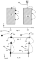
Fig. 2A schematically illustrates an embodiment of ameasuring device 103 measuring awork piece 200. Measurements of thework piece 200 taken by the coordinate measuringmachine 100 may be defined, for example, by their location in the X-Y-Z volume of the coordinate measuringmachine 100. For ease of explanation, examples herein are described in terms of an X-Y plane, with the understanding that the concepts apply to the X-Z plane, the Y-Z plane, or the X-Y-Z volume. - Illustrative embodiments measure a
work piece 200 by sequentially moving theprobe 105 to a set of target points 231-239, within themeasurement volume 111 of the coordinate measuringmachine 100, according to apre-established trajectory 220. Theprobe 105 may be a tactile probe, or an optical probe as known in the art of coordinate measuring machines. - As used herein and in any accompanying claims, a "pre-established measurement trajectory" (which may also be referred-to as an "established measurement trajectory" or a "command trajectory") is a predefined set of target points (for example, 231-239) specified in an order in which measurements of a
work piece 200 are to be taken. Thepre-established measurement trajectory 220 presumes that thework piece 200 is in a known orientation relative to themeasurement volume 111. Consequently, thework piece 200 may be considered as having an expected location and orientation relative to theCMM 100, and/or relative to the target points of apre-established trajectory 220. In other words, theCMM 100 expects thework piece 200 to have an expected location and orientation . Thepre-established trajectory 220 may be specific to thework piece 200, in that a CMM would measure anotherwork piece 200 with a different shape with a different pre-established trajectory. - As used herein and in any accompanying claims, a "target point" is a point having a coordinate location, within the
measurement volume 111 of a coordinate measuringmachine 100, to which the coordinate measuringmachine 100 moves aprobe 105 for purposes of measuring a corresponding place on awork piece 200. Each of the target points 231-239 of thepre-established trajectory 220 has a pre-defined location (e.g., an X-coordinate, a Y-coordinate, and a Z-coordinate) within themeasurement volume 111. In preferred embodiments, the target points 231-239 bear a specified spatial relationship with respect to one another in that the location of each of the specified target points 231-239 bears a fixed spatial relationship relative to each of the other specified points 231-239. In the embodiment ofFig. 2A , for example, each such fixed spatial relationship may be defined between a one of the specified target points (e.g. 231) and another (e.g., 232) as an X-offset distance along the X axis, and a Y offset distance in the Y axis. - In some embodiments, the
pre-established trajectory 220 also specifies a plurality of prescribed moves associated with the set of target points (for example, 221-229). As used herein and in any accompanying claims, a "prescribed move" is a path by which coordinate measuringmachine 100 moves a measuringprobe 105 from one target point in the set of target points (e.g., 231) to another target point (e.g., 232) in the set of points. Each such path may have a specified shape (e.g., a specified arc) configured to move theprobe 105 from one point (e.g., 231) to another (e.g., 232) in a method that avoids motion that is unnecessary, and/or that is configured to avoid undesirable contact with a portion of thework piece 200 and/or a portion of the coordinate measuringmachine 100. Motion of aprobe 105 may be deemed unnecessary if it increases, relative to another possible motion, the time or energy necessary for theprobe 105 to move from onetarget point 231 to the next 232, and/or if the motion does not reduce the likelihood that theprobe 105 will incur undesirable contact with a portion of thework piece 200 and/or a portion of the coordinate measuringmachine 100. The moves 221-229 may, in some embodiments, bear a specified spatial relationship with respect to one another in that the path of each of the specified moves 221-229 bears a fixed spatial relationship relative to each of the other specified moves 221-229, and/or a fixed spatial relationship relative to each of the specified points 231-239. - In operation, the coordinate measuring
machine 100 sequentially moves aprobe 105 to each of the target points 231-239, and takes corresponding measurements of thework piece 200, each such measurement associated with a one of the target points 231-239. A target point has been "measured," when the coordinate measuringmachine 100 directs aprobe 105 to a target point (e.g., 231) and takes a measurement of awork piece 200. Each of the acquired measurements has a location (e.g., an X-coordinate, a Y-coordinate, and a Z-coordinate) within themeasurement volume 111. Consequently, a trajectory (e.g., apre-established trajectory 220, and revisedtrajectories 270 described below) may be deemed to include the taking of measurements at target points (e.g., 231-239). - Taking a measurement of a
work piece 200 at a target point does not necessarily require that theprobe 105 actually reach, or be at, thetarget point 231 because, for example, theprobe 105 may encounter thework piece 200 prior to arriving at thetarget point 231 and measure the coordinate location of place upon encountering thework piece 200, or because theprobe 105 may move past thetarget point 231 prior to encountering, and measuring the coordinate location of, a place on, thework piece 200. For example, if thework piece 200 has an anomaly on its surface, the probe may encounter thework piece 200 prior to reaching a target point (e.g., when the anomaly is a protruding bump on the surface of the work piece and theprobe 105 encounters the bump prior to reaching a target point), or may not encounter the work piece until it reaches, or even passes, a target point (e.g., when the anomaly is an unexpected cavity or aperture in the surface of the work piece 200). In other words, unless thework piece 200 is missing, or is far from the location in which the coordinate measuringmachine 100 expects to find and measure it, the coordinate measuringmachine 100 is able to measure thework piece 200 from each target point 231-239 of apre-established trajectory 220. - Sometimes the
work piece 200 is mis-oriented relative to the coordinate measuringmachine 100, or relative to its expected location and orientation. For example, sometimes an operator places thework piece 200 on the coordinate measuringmachine 100 in an orientation different than an orientation specified or expected for execution of thepre-established trajectory 220. - For example,
Fig. 2B schematically illustrates a mis-orientedwork piece 200. For ease of illustration, thework piece 200 inFig. 2B is illustrated as having pivoted clockwise aboutpoint 231 ofFig. 2A , such thatpoint 231 ofFig. 2A is in the same location in the X-Y plane aspoint 251 ofFig. 2B . However, the described embodiments are not limited to mis-orientations produced by pivoting a work piece about a certain point. - Some embodiments of the coordinate measuring
machine 100 continuously scan a portion of awork piece 200 and produce a continuous measurement of that portion.Fig. 2H schematically illustrates an embodiment of awork piece 200 in a first orientation on aCMM 100, andFig. 2I schematically illustrates the same work piece in a different, second orientation on theCMM 100. Thework piece 200 has acurved portion 201. A continuous scan of thecurved portion 201 as oriented inFig. 2H produces acontinuous measurement 2201, as schematically illustrated inFig. 2J .Continuous measurement 2201 is the expected trajectory for when thework piece 200 is in its expected location, and is the pre-established trajectory (e.g., 220) for a continuous measurement. When thework piece 200 is mis-oriented, as inFig. 2I for example, the actual measurement is likewise mis-oriented, as shown by thecontinuous measurement 2401 inFig 2K . -
Fig. 2F and Fig. 2G schematically illustrate awork piece 200 that is laterally offset, along the X-axis, from an expectedposition 281 to anactual position 282. In this simple example, each point on thework piece 200 is laterally offset by a distance 283 (which may also be referred-to as a "linear offset" or "lateral offset"), along the X-axis, from its expectedlocation 281 in the X-Y plane to an offsetlocation 282, and each of thepoints probe 105 is laterally offset from its expected location. However, the described embodiments are not limited to mis-orientations produced by pivoting a lateral offset. -
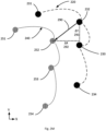
Fig. 2M schematically illustrates apre-established trajectory 220 and anactual trajectory 240 of awork piece 200 that is both rotationally offset and laterally offset. Such an offset may be referred-to as a "compound offset." Thepre-established trajectory 220 ofFig. 2M is identical to thepre-established trajectory 220 ofFig. 2C , and theactual trajectory 240 ofFig. 2M is identical to theactual trajectory 240 ofFig. 2C . - Due to such mis-orientation of the
work piece 200, the locations on awork piece 200 actually measured by the coordinate measuring machine are not in the position, in themeasurement volume 111, expected by the coordinate measuringmachine 100 executing thepre-established trajectory 220. Such mis-orientation causes a trajectory divergence between thepre-established trajectory 220 and the actual trajectory followed by theprobe 105. In some cases, execution of a portion of thepre-established trajectory 220 still is able to measure thework piece 200, but in extreme cases some target points of thepre-established trajectory 220 may be so far from the actual location of the work piece as to render the coordinate measuringmachine 100 unable to measure thework piece 200. - For example, in
Fig. 2B , each of thepoints actual moves actual trajectory 240. - A
trajectory divergence 260 of the rotationally-offsetwork piece 200 ofFig. 2B is schematically illustrated inFig. 2C , which shows that theactual trajectory 240 is rotated, by anangle 261, from thepre-established trajectory 220. Theangle 261 in this example is defined as the angle between afirst line 262 that passes through two consecutive points of the pre-established trajectory 220 (in this example,point 233 and point 234), and asecond line 264 that passes through two corresponding consecutive points of the actual trajectory 240 (in this example,point 253 and point 254). - In the continuous surface measurement example of
Figs. 2H, 2I, 2J, and 2K , the twocontinuous measurements trajectory divergence 260, as schematically illustrated inFig. 2L . Indeed, the twocontinuous measurements trajectory divergence 260. Thetrajectory divergence 260 may be used to produce an adapted trajectory for taking one or more subsequent continuous measurements of thework piece 200 as oriented inFig. 2I . - In the case of a lateral offset, such as schematically illustrated in
Fig. 2F and Fig. 2G , thefirst line 262 and thesecond line 264 are parallel to one another, and according to principles of geometry the slope of thefirst line 262 is equal to the slope of thesecond line 264. That thefirst line 262 is parallel to thesecond line 264 may be determined by comparing their slopes to one another. - In
Fig. 2M , theactual trajectory 240 is rotationally offset from thepre-established trajectory 220 at thesame angle 261 as inFig. 2C . The difference betweenFig. 2C andFig. 2M is that theactual trajectory 240 is also laterally offset from thepre-established trajectory 220. - Such offsets (e.g., a rotary offset, a lateral offset, or a compound offset) can reduce the accuracy of the measurement of the
work piece 200 as the coordinate measuringmachine 100 moves the probe 105 (for example, according tomoves probe 105 touches (in the case of a stylus) thework piece 200, and in some cases can make it impossible for the coordinate measuringmachine 100 to measure thework piece 200, or complete measurement of awork piece 200 after beginning its measurement ofsuch work piece 200. Moreover, such offsets can reduce the efficiency of the measurement process by increasing the motion of theprobe 105, and/or jeopardize the integrity of the measurement process and/or the safety of theprobe 105 and/or the safety of thework piece 200, by risking contact between theprobe 105 and a portion of thework piece 200 that is in an unexpected position. - The inventors have discovered, however, that measurements of some points (e.g., 251, 252) offset from their expected locations need not be fatal to the complete and successful measurement of the
work piece 200. Beneficially, according to various embodiments disclosed herein, successful measurement of thework piece 200 does not require re-orienting thework piece 200; does not require discarding measurements already taken (e.g., 251, 252); and does not require reinitiating the measurement of thework piece 200 from the beginning. Rather, as described herein, such previous measurement (e.g., 251, 252) may be used with subsequent measurements. -
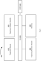
Fig. 3 is a flowchart of amethod 300 of measuring awork piece 200 according to various embodiments, andFig. 4 schematically illustrates asystem 400 configured to implement themethod 300. Thesystem 400 may be implemented using the components of a coordinate measuringmachine 100. In the description below, some or all of the actions attributed to thecomputer 130 could, in alternate embodiments, be performed instead by theprocessor 121 in thecontrol system 120. - At
step 301, the coordinate measuringmachine 100 receives thework piece 200, ifsuch work piece 200 has not previously been provided. For example, an operator may provide thework piece 200 to the coordinate measuringmachine 100, by placing thework piece 200 on the table 107 of the coordinate measuringmachine 100. - Step 302 provides, to the coordinate measuring
machine 100, apre-established trajectory 220, as described above in various embodiments. Such apre-established trajectory 220 may be programmed or hardwired into the coordinate measuringmachine 100, or may be sent to, or retrieved by, the coordinate measuringmachine 100 from amemory 440. For example, as illustrated inFig. 2A , thepre-established trajectory 220 may include a plurality of measurements to be executed sequentially in a given order, such as a measurement attarget point 231, followed by amove 221 to and measurement attarget point 232, and so forth formove 222 and measurement attarget point 233, and move 223 and measurement attarget point 234, etc. - At
step 303, thecontrol system 120 controls the coordinate measuringmachine 100 to execute a subset of, but not all of, the measurements and motions of thepre-established trajectory 220. In other words, atstep 303 the coordinate measuringmachine 100 acquires a plurality of measurements of thework piece 200, but fewer than all of the measurements specified by thepre-established trajectory 220. - This execution of a subset of, but not all of, the measurements and motions of the
pre-established trajectory 220, divides thepre-established trajectory 220 into two parts - and initial portion and a remainder, as described below. - (1) Initial Portion: The executed subset may be referred-to as the "initial portion" of the
pre-established trajectory 220. The plurality of acquired measurements may be referred to as the "initial acquired measurements," according to thepre-established measurement trajectory 220, and the points so measured may be referred to as the "initial set of target points," and the movements made by the coordinate measuring machine in executing those measurements may be referred to as the "initial movements." As used herein and in the accompanying claims, an "initial" set of target points is a subset of, but less than all of, the target points of apre-established measurement trajectory 220, which subset has been measured by the coordinate measuringmachine 100. The measurements taken at step 303 (i.e., the X-Y-Z coordinate data produced by taking each measurement) are stored inmemory 440 atstep 304. - (2) Remainder. The target points of the
pre-established trajectory 220 not yet measured (i.e., the measurements of thepre-established trajectory 220 that are not included within the initial portion) may be referred-to as a remainder of target points (or remaining target points). As used herein and in the accompanying claims, a "remainder" of target points is a subset of target points of an established measurement trajectory. As one example, for a given established measurement trajectory, the "remainder" of target points is that subset of target points of the given established measurement trajectory that remain unmeasured after the coordinate measuring machine has taken measurements at an initial set of target points from the established measurement trajectory. - At
step 305, prior to completing execution of the pre-established trajectory 220 (e.g., prior to taking the remainder of measurements) acomputer 130 analyzes theactual trajectory 240 to determine thetrajectory divergence 260. - In preferred embodiments, analysis of the
actual trajectory 240 uses two consecutive measurements from among the initial acquired measurements. More specifically, revising a given trajectory based on two measurements of awork piece 200 is more accurate than revising that given trajectory based on measurement of a single point on thework piece 200. For example, based only on a measurement of asingle target point 231 on awork piece 200, the coordinate measuringmachine 100 would be unable to distinguish between a mis-orientedwork piece 200, and awork piece 200 that has a surface anomaly such as a bump or cavity, and therefore would have no basis on which to revise the remainder target points of an established trajectory to reorient those remainder of target points to accommodate a mis-orientedwork piece 200. - Then, at
step 306, thecomputer 130 produces a revisedtrajectory 270. In preferred embodiments, thecomputer 130 produces a revisedtrajectory 270 based on the un-executed moves and measurements of the pre-established trajectory by shifting at least some of the remainder target points (e.g., 235-239) to align them with the actual orientation of thework piece 200. It will be understood that each point of the revised set of target points (e.g., inFig. 2E , target point 2352-2392) has a coordinate location that is different from the coordinate location of the target points of the target points (e.g., 235-230) of the originalpre-established trajectory 220. In preferred embodiments, step 306 also produces a revised set of prescribed moves (2252-2282) associated with the revised set of target points (2352-2392). - Based on actual measurements taken of the work piece, the trajectory is adaptively updated to reduce the trajectory divergence in subsequent measurements of the
work piece 200. - In the example of the offset
work piece 200 ofFig. 2B , the computer rotationally shifts the location of the unexecuted target points 235-239 and moves 224-228 to revised locations, in the X-Y plane. Because thepre-established trajectory 220 and theactual trajectory 240 are offset byangle 261, the rotational shift of each of the unexecuted target points 235-239, in this example, is an arc. The length and geometry of the arc may be determined by the rotational offset of the work piece (e.g., angle 261), and the distance of the unexecuted target point from the axis of rotation (in this example, point 231), according to principles of geometry. As an example,Fig. 2D schematically represents a shift ofpoint 235 from the location illustrated inFig. 2A to its revised location illustrated inFig. 2B by thearc 265. The revisedtrajectory 270 thus includes the shifted target points 2352-2392, which align with orientation thework piece 200, as schematically illustrated inFig. 2E . - Because the
pre-established trajectory 220 and theactual trajectory 240 are, inFig. 2F and Fig. 2G , offset by thatdistance 283 along the X-axis, the shift of each of the unmeasured target points 235-239 to create a revisedtrajectory 270, in this example, is a linear shift ofdistance 283 along the X-axis. - Because, in
Fig. 2M , theactual trajectory 240 is both rotationally offset and laterally offset from thepre-established trajectory 220, the shift of each of the unmeasured target points 235-239 to create a revised trajectory addresses both offsets. For example, such a shift may be determined by a two-stage process. First, define ashift vector 290 as the difference in coordinates between a given one of the target points (e.g. 231 or 232) to a corresponding actual measurement point (e.g., 251 or 252, respectively). For example, inFig. 2M , theshift vector 290 is defined by a difference in the position oftarget point 231 and the position ofactual measurement point 252 by a difference 291 (ΔY) in the Y axis and by a difference 292 (ΔX) in the X axis. Second, shifting each of the remainder points by theshift vector 290. As an illustrative example, iftarget point 231 is shifted byvector 290, then targetpoint 231 will correspond toactual measurement point 251. Although theshift vector 290 described above and illustrated inFig. 2M includes offsets only in the X axis and Y axis, the same principle applies to offsets in the Z axis as well. - Subsequently, the
angle 261 may be found, and remainder points may be rotated, as described in connection withFig. 2C and Fig. 2D . As can be understood fromFig. 2M as described above, shifting the remainder of target points in space includes both linearly offsetting the remainder of target points in space, and rotationally offsetting the remainder of target points in space, to match both a linear offset and a rotational offset of the work piece. - In some embodiments, the target points 2352-2392 of the revised
trajectory 270 have (or maintain) the same fixed spatial relationship relative to one another as their counterparts 235-239 in thepre-established trajectory 220. In some embodiments, the unexecuted moves 2242-2282 of the revisedtrajectory 270 have (or maintain) the fixed spatial relationship relative to as their counterparts 223-228, and the target points 235-239, as have in thepre-established trajectory 220. In other words, in such embodiments, the production of the revisedtrajectory 270 atstep 306 does not change those fixed spatial relationships. This can be beneficial because it re-uses (by re-orienting) portions of the pre-established target points 235-239 and moves 224-228 of thepre-established trajectory 220, without having to discard measurements made before analyzing the actual trajectory 240 (e.g. 251, 252, etc.), and/or re-orient thework piece 200 and re-initiate the measurement of thework piece 200, and/or calculate an entirely new trajectory. Moreover, re-use of the shifted pre-established target points 235-239 and moves 224-228 of the pre-established trajectory gains the benefits thereof, such as efficiency, and/or measurement integrity, and/or the safety of theprobe 105, and/or the safety of the work piece, as described above. - Then, at
step 307, the computer 130 (and/or the control system 120) controls the coordinate measuringmachine 100 to continue its measurement of thework piece 200 by executing the adaptively revisedtrajectory 270. More specifically, step 307 controls the coordinate measuringmachine 100 to continue its measurement of thework piece 200 from the point at which is left off (e.g., frompoint 254, if that was the last point measured before analysis of the actual trajectory at step 305). The measurements taken at step 307 (i.e., the data produced by taking each measurement) may be referred to as "later measurements" (or "remainder" measurements) and are stored inmemory 440 atstep 308. - In some embodiments, the
method 300 may loop, 320, fromstep 307 back to step 305 after executing a subset of the revised trajectory. In such embodiments,step 305 assesses the actual trajectory generated by execution of the revisedtrajectory 270, and step 306 produces a new revised trajectory, and the coordinate measuring machine executes that new revised trajectory atstep 307. The method may continue until the coordinate measuringmachine 100 completes all moves and measurements of the revisedtrajectory 270. - In some embodiments, one or more places on the
work piece 200 may (optionally) be re-measured atstep 309, and the measurements taken at step 309 (i.e., the data produced by taking each re-measurement, which may be referred-to as "re-measurements") are stored inmemory 440. - For example, in some embodiments, a
pre-established trajectory 220, or revisedtrajectory 270, may include re-measuring one or more points from the beginning of thepre-established trajectory 220. For example,Fig. 2A schematically illustrates apre-established trajectory 220 in which point 231 is the first point measured in the pre-established trajectory, and thatpoint 231 is re-measured aftermove 229. Re-measuring one or more previously-measured points in this way can indicate or assure, if the second measurements are the same at the previous measurements, that thework piece 200 has not moved during themeasurement process 300. - At
step 310, the method retrieves the measurement data (i.e., the initial measurements, the later measurements, and, if any, the re-measurements) stored inmemory 440, and evaluates the work piece by analyzing that retrieved measurement data in ways known in the art. For example, evaluation of the work piece may include comparing the retrieved measurement data to one or more measurement specifications or a computer-aided-design ("CAD") model for the work piece. - As can be understood from the foregoing description, a
probe 105 of a coordinate measuringmachine 100 is a sensor that monitors aspects of the operation of the coordinate measuringmachine 100, and thereby contributes to the operation of the coordinate measuringmachine 100. In some embodiments, themethod 300 may be described as being open-loop in that it does not include feedback for every move 221-229 or target point 231-239 executed by the coordinate measuringmachine 100, meaning that some moves 221-229 and target points 231-239 are made without the benefit of feedback. Because themethod 300 revises the trajectory after beginning the measurement process, but prior to completing the measurement process, the operation may be described as dynamically adapting the operation of the coordinate measuringmachine 100. - The
system 400 ofFig. 4 may be implemented, in whole or in part, on a coordinate measuringmachine 100 with acontrol system 120 and/or acomputer 130, as described above. Thesystem 400 includes atrajectory module 410 configured to receive and storepre-established trajectory 220 and one or more revisedtrajectories 270. Thetrajectory module 410 is in data communication with thecontrol system 120 and/orcomputer 130 to provide, to thecontrol system 120 and/or acomputer 130, thepre-established trajectory 220 and one or more revisedtrajectories 270. - The
system 400 also includes atrajectory analysis module 420 configured to analyze theactual trajectory 240 atstep 305, as described above. - In addition, the
system 400 includes atrajectory revision module 430 configured to generate a revised trajectory atstep 306, as described above. - The
system 400 also includes amemory 440 in data communication with one or more of thetrajectory module 410,trajectory analysis module 420, and thetrajectory generation module 430. Thememory 440 may be part of thecontrol system 120 and/or acomputer 130, or may be a separate memory. - The
memory 440 may be configured to store computer code configured to execute on a computer processor to implement one or more of the functions oftrajectory module 410,trajectory analysis module 420, and thetrajectory generation module 430. Thememory 440 may also be configured to store measurement data taken of awork piece 200 by theCMM 100. - In the embodiment of
Fig. 4 , themodules machine 100, via a bus 401. Alternatively, or in addition, some or all of themodules control system 120 and/or thecomputer 130. - The following is a list of reference numbers used herein:
- 100: Coordinate measuring machine;
- 101: Floor;
- 102: Base;
- 103: Measuring device;
- 104: CMM arm;
- 105: Probe;
- 107: Table;
- 110: X-Y plane;
- 111: Measurement volume;
- 120: Control system;
- 121: Computer processor;
- 122: Sensors/movable features;
- 125: CMM user interface;
- 125A: Control buttons;
- 125B: Control knobs;
- 130: Host computer;
- 131: Cable;
- 200: Work piece;
- 220: Pre-established trajectory;
- 221-228: Moves of pre-established trajectory;
- 2242-2282: Shifted moves;
- 231-239: Target points;
- 2352-2392: Shifted target points;
- 240: Actual trajectory;
- 241-249: Moves of actual trajectory;
- 251-259: Points actually measured;
- 260: Trajectory delta;
- 261: Angular offset;
- 262: Linear characterization of pre-established trajectory;
- 264: Linear characterization of actual trajectory;
- 265: Arc shift;
- 270: Revised trajectory;
- 281: Presumed position of work piece;
- 282: Laterally shifted position of work piece;
- 283: Lateral offset;
- 290: Shift vector
- 300: Flow chart of method;
- 301-310, 320: Method steps;
- 400: System;
- 401: System bus;
- 410: Trajectory module;
- 420: Trajectory analysis module;
- 430: Trajectory revision generation module;
- 440: Memory.
- Various embodiments of the invention may be implemented at least in part in any conventional computer programming language. For example, some embodiments may be implemented in a procedural programming language (e.g., "C"), or in an object oriented programming language (e.g., "C++"). Other embodiments of the invention may be implemented as preprogrammed hardware elements (e.g., application specific integrated circuits, FPGAs, and digital signal processors), or other related components.
- In an alternative embodiment, the disclosed apparatus and methods may be implemented as a computer program product for use with a computer system. Such implementation may include a series of computer instructions fixed on a tangible medium, such as a non-transient computer readable medium (e.g., a diskette, CD-ROM, ROM, FLASH memory, or fixed disk). The series of computer instructions can embody all or part of the functionality previously described herein with respect to the system.
- Those skilled in the art should appreciate that such computer instructions can be written in a number of programming languages for use with many computer architectures or operating systems. Furthermore, such instructions may be stored in any memory device, such as semiconductor, magnetic, optical or other memory devices, and may be transmitted using any communications technology, such as optical, infrared, microwave, or other transmission technologies.
- Among other ways, such a computer program product may be distributed as a removable medium with accompanying printed or electronic documentation (e.g., shrink wrapped software), preloaded with a computer system (e.g., on system ROM or fixed disk), or distributed from a server or electronic bulletin board over the network (e.g., the Internet or World Wide Web). Of course, some embodiments of the invention may be implemented as a combination of both software (e.g., a computer program product) and hardware. Still other embodiments of the invention are implemented as entirely hardware, or entirely software.
- The embodiments of the invention described above are intended to be merely exemplary; numerous variations and modifications will be apparent to those skilled in the art.
Claims (15)
- A system (400) for measuring a work piece (200), the system comprising:a trajectory module (410) configured to store an established measurement trajectory;a controller in data communication with the trajectory module to receive, from the trajectory module, the established measurement trajectory, and configured to control a measuring probe (105) according to a subset of, but less than all of, the established measurement trajectory;a trajectory analysis module (420) configured to analyze an actual trajectory (240) executed by the measuring probe (105), relative to the established measurement trajectory, based on measurements of the work piece taken according to at least two consecutive target points (231-239) of the established measurement trajectory, and to produce a trajectory divergence; anda trajectory revision module (430) configured to generate a revised trajectory (270) for acquiring a remainder of the measurements based on the established measurement trajectory and the trajectory divergence,the controller configured to control the measuring probe to measure the work piece according to the revised trajectory.
- The system of claim 1, wherein:the established measurement trajectory includes a plurality of target points (231-239), the plurality of target points having a fixed spatial relationship relative to one another; andgenerating a revised trajectory (270) includes retaining the fixed spatial relationship of the measurements relative to one another.
- The system of claim 2, wherein:
the established measurement trajectory further includes a plurality of moves corresponding to the plurality of target points (231-239), each move defining a path, followed by the measuring probe (105), between consecutive target points. - The system of claim 2, wherein:the established measurement trajectory further comprises a plurality of moves corresponding to the plurality of target points (231-239), each move defining a path, followed by the measuring probe (105), between consecutive target points, the plurality of moves having a fixed spatial relationship relative to one another; andgenerating a revised trajectory (270) includes retaining the fixed spatial relationship of the moves relative to one another.
- The system of claim 1, wherein generating a revised trajectory (270) includes shifting a subset of target points (231-239) of the established measurement trajectory by linearly offsetting the subset of target points in space to match a linear offset of the work piece (200), orwherein generating a revised trajectory includes shifting a subset of target points of the established measurement trajectory by rotationally offsetting the subset of target points in space to match a rotational offset of the work piece, orwherein generating a revised trajectory includes both:linearly offsetting each point of the subset of target points, androtationally offsetting each point of the subset of target points, to match both a linear offset and a rotational offset of the work piece.
- A method of dynamically adapting the operation of a coordinate measuring machine (100) while measuring a work piece (200), the method including:providing, to the coordinate measuring machine, an established measurement trajectory comprising a plurality of pre-defined target points (231-239), each of the plurality of pre-defined target points having a coordinate location;controlling the coordinate measuring machine to acquire a plurality of initial acquired measurements of the work piece according to an initial set of target points, the initial set of target points being a subset of the plurality of pre-defined target points, the initial set of pre-defined target points defining a remainder of target points;storing the plurality of initial acquired measurements in a memory (440);after controlling the coordinate measuring machine to acquire the plurality of initial acquired measurements , but prior to completing execution of the established measurement trajectory, establishing a trajectory divergence based on at least two of the plurality of initial acquired measurements;based on the trajectory divergence, producing a re-oriented set of target points from the remainder of target points, the re-oriented set of target points configured to reduce the trajectory divergence;controlling the coordinate measuring machine to continue measuring the work piece (200) according to the re-oriented set of target points, thereby acquiring a remainder of measurements; andstoring the remainder of measurements in the memory.
- The method of claim 6, wherein:the pre-defined target points (231-239) of the established measurement trajectory have a fixed spatial relationship relative to one another; andproducing a re-oriented set of target points comprises shifting the remainder of target points in space, but retaining the fixed spatial relationship of the remainder of target points relative to one another.
- The method of claim 7, wherein:
the established measurement trajectory further includes a plurality of moves corresponding to the plurality of pre-defined target points (231-239), each move of the plurality of moves defining a path, followed by a probe (105) of the coordinate measuring machine (100), between consecutive ones of the pre-defined target points. - The method of claim 7, wherein:the established measurement trajectory further comprises a plurality of moves corresponding to the plurality of pre-defined target points (231-239), each move defining a path, followed by a probe (105) of the coordinate measuring machine (100), between consecutive ones of the pre-defined target points, the plurality of moves having a fixed spatial relationship relative to one another; andproducing a re-oriented set of target points comprises shifting the remainder of target points in space, but retaining the fixed spatial relationship of the moves relative to one another.
- The method of claim 7, wherein shifting the remainder of target points (231-239) in space comprises linearly offsetting each of the remainder of target points in space to match a linear offset of the work piece (200), orwherein shifting the remainder of target points in space comprises rotationally offsetting the remainder of target points in space to match a rotational offset of the work piece, orwherein shifting the remainder of target points in space comprises both:linearly offsetting the remainder of target points in space, androtationally offsetting the remainder of target points in space, to match both a linear offset and a rotational offset of the work piece.
- A non-transient computer programmed product bearing non-transient executable computer code which, when executed by a computer processor (121), control a coordinate measuring machine (100), the executable computer code comprising:code for causing a controller to measure a work piece (200) according to each of two target points (231-239) of a an established measurement trajectory, each of the two target points having a pre-established coordinate location according to the established measurement trajectory, to produce two corresponding location measurements, the two target points defining a remainder of target points of the established measurement trajectory;code for assessing, prior to completing execution of the established measurement trajectory, an orientation of the work piece by processing the two location measurements relative to the pre-established coordinate locationscode for producing a re-oriented set of target points from the remainder of target points of the established measurement trajectory; andcode for controlling the coordinate measuring machine to continue measuring the work piece by measuring the work piece according to the re-oriented set of target points.
- The non-transient computer programmed product of claim 11, wherein:the established measurement trajectory includes a plurality of target points (231-239), the plurality of target points having a fixed spatial relationship relative to one another; andcode for producing a re-oriented set of target points comprises code for shifting the remainder of target points in space, but retaining the fixed spatial relationship of the remainder of target points relative to one another.
- The non-transient computer programmed product of claim 12, wherein:
the established measurement trajectory further includes a plurality of moves corresponding to the plurality of target points (231-239), each move defining a path, followed by a probe (105) of the coordinate measuring machine (100), between consecutive target points. - The non-transient computer programmed product of claim 12, wherein:the established measurement trajectory further comprises a plurality of moves corresponding to the plurality of target points (231-239), each move defining a path, followed by a probe (105) of the coordinate measuring machine (100), between consecutive target points, the plurality of moves having a fixed spatial relationship relative to one another; andcode for producing a re-oriented set of target points comprises code for shifting the remainder of target points in space, but retaining the fixed spatial relationship of the remainder of target points relative to one another.
- The non-transient computer programmed product of claim 14, wherein code for shifting the remainder of target points (231-239) in space comprises code for linearly offsetting the remainder of target points in space to match a linear offset of the work piece (200), or
wherein code for shifting the remainder of target points in space comprises code for rotationally offsetting the remainder of target points in space to match a rotational offset of the work piece.
Applications Claiming Priority (2)
| Application Number | Priority Date | Filing Date | Title |
|---|---|---|---|
| US15/953,891 US11231262B2 (en) | 2018-04-16 | 2018-04-16 | Dynamically adapting operation of a coordinate measuring machine |
| PCT/US2019/025328 WO2019204028A1 (en) | 2018-04-16 | 2019-04-02 | Dynamically adapting operation of a coordinate measuring machine |
Publications (2)
| Publication Number | Publication Date |
|---|---|
| EP3781901A1 EP3781901A1 (en) | 2021-02-24 |
| EP3781901B1 true EP3781901B1 (en) | 2023-07-05 |
Family
ID=66182668
Family Applications (1)
| Application Number | Title | Priority Date | Filing Date |
|---|---|---|---|
| EP19718027.6A Active EP3781901B1 (en) | 2018-04-16 | 2019-04-02 | Dynamically adapting operation of a coordinate measuring machine |
Country Status (3)
| Country | Link |
|---|---|
| US (1) | US11231262B2 (en) |
| EP (1) | EP3781901B1 (en) |
| WO (1) | WO2019204028A1 (en) |
Families Citing this family (4)
| Publication number | Priority date | Publication date | Assignee | Title |
|---|---|---|---|---|
| JP6923361B2 (en) * | 2017-05-29 | 2021-08-18 | 株式会社ミツトヨ | How to operate the position measuring device |
| EP3835713B1 (en) * | 2019-12-10 | 2022-07-13 | Carl Zeiss Industrielle Messtechnik GmbH | Method for determining the dimensions of a measuring object by means of a coordinate measuring device |
| DE102020200309B4 (en) * | 2020-01-13 | 2022-05-12 | Carl Zeiss Industrielle Messtechnik Gmbh | Method and device for planning an obstacle-free measurement trajectory of a coordinate measuring machine and computer program |
| EP4235325A3 (en) * | 2020-04-21 | 2023-09-20 | Carl Zeiss Industrielle Messtechnik GmbH | Method and device for determining measuring points of an adapted measuring path for measuring a measuring object by a coordinate measuring device and program |
Family Cites Families (4)
| Publication number | Priority date | Publication date | Assignee | Title |
|---|---|---|---|---|
| DE4245012B4 (en) | 1992-04-14 | 2004-09-23 | Carl Zeiss | Method for measuring shaped elements on a coordinate measuring machine |
| JP4782990B2 (en) | 2004-05-31 | 2011-09-28 | 株式会社ミツトヨ | Surface scanning measuring device, surface scanning measuring method, surface scanning measuring program, and recording medium |
| JP6484108B2 (en) * | 2015-05-22 | 2019-03-13 | 株式会社ミツトヨ | Method for controlling shape measuring apparatus |
| GB201616415D0 (en) | 2016-09-28 | 2016-11-09 | Renishaw Plc | A method and apparatus for measuring an object |
-
2018
- 2018-04-16 US US15/953,891 patent/US11231262B2/en active Active
-
2019
- 2019-04-02 EP EP19718027.6A patent/EP3781901B1/en active Active
- 2019-04-02 WO PCT/US2019/025328 patent/WO2019204028A1/en unknown
Also Published As
| Publication number | Publication date |
|---|---|
| US20190316893A1 (en) | 2019-10-17 |
| WO2019204028A1 (en) | 2019-10-24 |
| US11231262B2 (en) | 2022-01-25 |
| EP3781901A1 (en) | 2021-02-24 |
Similar Documents
| Publication | Publication Date | Title |
|---|---|---|
| EP3781901B1 (en) | Dynamically adapting operation of a coordinate measuring machine | |
| US11498214B2 (en) | Teaching device, teaching method, and robot system | |
| EP3303991B1 (en) | Coordinate measuring machine with object location logic | |
| US10545019B2 (en) | CMM probe path controller and method | |
| US10173324B2 (en) | Facilitating robot positioning | |
| CN107428009B (en) | Method for commissioning an industrial robot, industrial robot system and control system using the method | |
| US10534876B2 (en) | Simulation device and simulation method that carry out simulation of operation of robot system, and recording medium that records computer program | |
| JP2014128845A (en) | Robot system display device | |
| US11345026B2 (en) | Robot program generation apparatus | |
| JP6915441B2 (en) | Information processing equipment, information processing methods, and information processing programs | |
| JP2018161700A (en) | Information processing device, system, information processing method, and manufacturing method | |
| CN110977980A (en) | Mechanical arm real-time hand-eye calibration method and system based on optical position indicator | |
| JP2017037460A (en) | Machining system and machining method | |
| KR101650011B1 (en) | Method of setting inspection criteria coordinate by aligning geometry created by 3D scanner | |
| JP2019089201A (en) | Teaching data creation device, method for controlling teaching data creation device, and robot system | |
| JP2009288107A (en) | Shape measuring apparatus, method and program | |
| US11965736B2 (en) | Measurement routine motion represented by 3D virtual model | |
| JP2017121691A (en) | Robot point position adjustment control method and system | |
| JP2015222196A (en) | Three dimensional measuring machine and method for measuring shape using the same | |
| US20210041851A1 (en) | Machining program generation support device | |
| US11428524B2 (en) | Method and device for generating a pulsed signal at particular positions of a moving element | |
| CN115476338B (en) | Gesture adjustment method and device, robot mechanism, electronic device and storage medium | |
| JP6079352B2 (en) | ROBOT CONTROL METHOD, ROBOT CONTROL DEVICE, ROBOT, ROBOT SYSTEM, AND PROGRAM | |
| EP4309855A1 (en) | A method of using a robotic arm to position a part | |
| US20220219328A1 (en) | Method and device for creation of three dimensional tool frame |
Legal Events
| Date | Code | Title | Description |
|---|---|---|---|
| STAA | Information on the status of an ep patent application or granted ep patent |
Free format text: STATUS: UNKNOWN |
|
| STAA | Information on the status of an ep patent application or granted ep patent |
Free format text: STATUS: THE INTERNATIONAL PUBLICATION HAS BEEN MADE |
|
| PUAI | Public reference made under article 153(3) epc to a published international application that has entered the european phase |
Free format text: ORIGINAL CODE: 0009012 |
|
| STAA | Information on the status of an ep patent application or granted ep patent |
Free format text: STATUS: REQUEST FOR EXAMINATION WAS MADE |
|
| 17P | Request for examination filed |
Effective date: 20201028 |
|
| AK | Designated contracting states |
Kind code of ref document: A1 Designated state(s): AL AT BE BG CH CY CZ DE DK EE ES FI FR GB GR HR HU IE IS IT LI LT LU LV MC MK MT NL NO PL PT RO RS SE SI SK SM TR |
|
| AX | Request for extension of the european patent |
Extension state: BA ME |
|
| DAV | Request for validation of the european patent (deleted) | ||
| DAX | Request for extension of the european patent (deleted) | ||
| GRAJ | Information related to disapproval of communication of intention to grant by the applicant or resumption of examination proceedings by the epo deleted |
Free format text: ORIGINAL CODE: EPIDOSDIGR1 |
|
| STAA | Information on the status of an ep patent application or granted ep patent |
Free format text: STATUS: GRANT OF PATENT IS INTENDED |
|
| GRAP | Despatch of communication of intention to grant a patent |
Free format text: ORIGINAL CODE: EPIDOSNIGR1 |
|
| INTG | Intention to grant announced |
Effective date: 20230207 |
|
| RAP3 | Party data changed (applicant data changed or rights of an application transferred) |
Owner name: HEXAGON METROLOGY, INC. |
|
| GRAS | Grant fee paid |
Free format text: ORIGINAL CODE: EPIDOSNIGR3 |
|
| GRAA | (expected) grant |
Free format text: ORIGINAL CODE: 0009210 |
|
| STAA | Information on the status of an ep patent application or granted ep patent |
Free format text: STATUS: THE PATENT HAS BEEN GRANTED |
|
| AK | Designated contracting states |
Kind code of ref document: B1 Designated state(s): AL AT BE BG CH CY CZ DE DK EE ES FI FR GB GR HR HU IE IS IT LI LT LU LV MC MK MT NL NO PL PT RO RS SE SI SK SM TR |
|
| REG | Reference to a national code |
Ref country code: CH Ref legal event code: EP |
|
| REG | Reference to a national code |
Ref country code: AT Ref legal event code: REF Ref document number: 1585211 Country of ref document: AT Kind code of ref document: T Effective date: 20230715 |
|
| REG | Reference to a national code |
Ref country code: DE Ref legal event code: R096 Ref document number: 602019032112 Country of ref document: DE |
|
| REG | Reference to a national code |
Ref country code: IE Ref legal event code: FG4D |
|
| REG | Reference to a national code |
Ref country code: SE Ref legal event code: TRGR |
|
| REG | Reference to a national code |
Ref country code: NL Ref legal event code: FP |
|
| REG | Reference to a national code |
Ref country code: LT Ref legal event code: MG9D |
|
| REG | Reference to a national code |
Ref country code: AT Ref legal event code: MK05 Ref document number: 1585211 Country of ref document: AT Kind code of ref document: T Effective date: 20230705 |
|
| PG25 | Lapsed in a contracting state [announced via postgrant information from national office to epo] |
Ref country code: GR Free format text: LAPSE BECAUSE OF FAILURE TO SUBMIT A TRANSLATION OF THE DESCRIPTION OR TO PAY THE FEE WITHIN THE PRESCRIBED TIME-LIMIT Effective date: 20231006 |
|
| PG25 | Lapsed in a contracting state [announced via postgrant information from national office to epo] |
Ref country code: ES Free format text: LAPSE BECAUSE OF FAILURE TO SUBMIT A TRANSLATION OF THE DESCRIPTION OR TO PAY THE FEE WITHIN THE PRESCRIBED TIME-LIMIT Effective date: 20230705 |
|
| PG25 | Lapsed in a contracting state [announced via postgrant information from national office to epo] |
Ref country code: IS Free format text: LAPSE BECAUSE OF FAILURE TO SUBMIT A TRANSLATION OF THE DESCRIPTION OR TO PAY THE FEE WITHIN THE PRESCRIBED TIME-LIMIT Effective date: 20231105 |
|
| PG25 | Lapsed in a contracting state [announced via postgrant information from national office to epo] |
Ref country code: RS Free format text: LAPSE BECAUSE OF FAILURE TO SUBMIT A TRANSLATION OF THE DESCRIPTION OR TO PAY THE FEE WITHIN THE PRESCRIBED TIME-LIMIT Effective date: 20230705 Ref country code: PT Free format text: LAPSE BECAUSE OF FAILURE TO SUBMIT A TRANSLATION OF THE DESCRIPTION OR TO PAY THE FEE WITHIN THE PRESCRIBED TIME-LIMIT Effective date: 20231106 Ref country code: NO Free format text: LAPSE BECAUSE OF FAILURE TO SUBMIT A TRANSLATION OF THE DESCRIPTION OR TO PAY THE FEE WITHIN THE PRESCRIBED TIME-LIMIT Effective date: 20231005 Ref country code: LV Free format text: LAPSE BECAUSE OF FAILURE TO SUBMIT A TRANSLATION OF THE DESCRIPTION OR TO PAY THE FEE WITHIN THE PRESCRIBED TIME-LIMIT Effective date: 20230705 Ref country code: LT Free format text: LAPSE BECAUSE OF FAILURE TO SUBMIT A TRANSLATION OF THE DESCRIPTION OR TO PAY THE FEE WITHIN THE PRESCRIBED TIME-LIMIT Effective date: 20230705 Ref country code: IS Free format text: LAPSE BECAUSE OF FAILURE TO SUBMIT A TRANSLATION OF THE DESCRIPTION OR TO PAY THE FEE WITHIN THE PRESCRIBED TIME-LIMIT Effective date: 20231105 Ref country code: HR Free format text: LAPSE BECAUSE OF FAILURE TO SUBMIT A TRANSLATION OF THE DESCRIPTION OR TO PAY THE FEE WITHIN THE PRESCRIBED TIME-LIMIT Effective date: 20230705 Ref country code: GR Free format text: LAPSE BECAUSE OF FAILURE TO SUBMIT A TRANSLATION OF THE DESCRIPTION OR TO PAY THE FEE WITHIN THE PRESCRIBED TIME-LIMIT Effective date: 20231006 Ref country code: FI Free format text: LAPSE BECAUSE OF FAILURE TO SUBMIT A TRANSLATION OF THE DESCRIPTION OR TO PAY THE FEE WITHIN THE PRESCRIBED TIME-LIMIT Effective date: 20230705 Ref country code: ES Free format text: LAPSE BECAUSE OF FAILURE TO SUBMIT A TRANSLATION OF THE DESCRIPTION OR TO PAY THE FEE WITHIN THE PRESCRIBED TIME-LIMIT Effective date: 20230705 Ref country code: AT Free format text: LAPSE BECAUSE OF FAILURE TO SUBMIT A TRANSLATION OF THE DESCRIPTION OR TO PAY THE FEE WITHIN THE PRESCRIBED TIME-LIMIT Effective date: 20230705 |
|
| PG25 | Lapsed in a contracting state [announced via postgrant information from national office to epo] |
Ref country code: PL Free format text: LAPSE BECAUSE OF FAILURE TO SUBMIT A TRANSLATION OF THE DESCRIPTION OR TO PAY THE FEE WITHIN THE PRESCRIBED TIME-LIMIT Effective date: 20230705 |
|
| PLBI | Opposition filed |
Free format text: ORIGINAL CODE: 0009260 |