EP3781699B1 - Elektroden für biosensoren - Google Patents
Elektroden für biosensoren Download PDFInfo
- Publication number
- EP3781699B1 EP3781699B1 EP19722378.7A EP19722378A EP3781699B1 EP 3781699 B1 EP3781699 B1 EP 3781699B1 EP 19722378 A EP19722378 A EP 19722378A EP 3781699 B1 EP3781699 B1 EP 3781699B1
- Authority
- EP
- European Patent Office
- Prior art keywords
- ruthenium
- nickel
- alloy
- electrode
- layer
- Prior art date
- Legal status (The legal status is an assumption and is not a legal conclusion. Google has not performed a legal analysis and makes no representation as to the accuracy of the status listed.)
- Active
Links
- PXHVJJICTQNCMI-UHFFFAOYSA-N Nickel Chemical compound [Ni] PXHVJJICTQNCMI-UHFFFAOYSA-N 0.000 claims description 288
- KJTLSVCANCCWHF-UHFFFAOYSA-N Ruthenium Chemical compound [Ru] KJTLSVCANCCWHF-UHFFFAOYSA-N 0.000 claims description 202
- 229910052707 ruthenium Inorganic materials 0.000 claims description 192
- 229910052759 nickel Inorganic materials 0.000 claims description 137
- 229910045601 alloy Inorganic materials 0.000 claims description 97
- 239000000956 alloy Substances 0.000 claims description 97
- 229910001092 metal group alloy Inorganic materials 0.000 claims description 66
- 239000011651 chromium Substances 0.000 claims description 62
- 229910052782 aluminium Inorganic materials 0.000 claims description 61
- XAGFODPZIPBFFR-UHFFFAOYSA-N aluminium Chemical compound [Al] XAGFODPZIPBFFR-UHFFFAOYSA-N 0.000 claims description 57
- 229910052751 metal Inorganic materials 0.000 claims description 54
- 239000002184 metal Substances 0.000 claims description 54
- 239000010931 gold Substances 0.000 claims description 53
- 238000005275 alloying Methods 0.000 claims description 50
- 239000003153 chemical reaction reagent Substances 0.000 claims description 47
- 229910002056 binary alloy Inorganic materials 0.000 claims description 45
- 229910052804 chromium Inorganic materials 0.000 claims description 45
- 239000000758 substrate Substances 0.000 claims description 43
- VYZAMTAEIAYCRO-UHFFFAOYSA-N Chromium Chemical compound [Cr] VYZAMTAEIAYCRO-UHFFFAOYSA-N 0.000 claims description 41
- PCHJSUWPFVWCPO-UHFFFAOYSA-N gold Chemical compound [Au] PCHJSUWPFVWCPO-UHFFFAOYSA-N 0.000 claims description 38
- 229910052737 gold Inorganic materials 0.000 claims description 38
- KDLHZDBZIXYQEI-UHFFFAOYSA-N Palladium Chemical compound [Pd] KDLHZDBZIXYQEI-UHFFFAOYSA-N 0.000 claims description 36
- 239000010936 titanium Substances 0.000 claims description 34
- RTAQQCXQSZGOHL-UHFFFAOYSA-N Titanium Chemical compound [Ti] RTAQQCXQSZGOHL-UHFFFAOYSA-N 0.000 claims description 29
- 229910052719 titanium Inorganic materials 0.000 claims description 29
- 239000000463 material Substances 0.000 claims description 28
- 229910002058 ternary alloy Inorganic materials 0.000 claims description 25
- 239000010949 copper Substances 0.000 claims description 23
- 229910052715 tantalum Inorganic materials 0.000 claims description 23
- GUVRBAGPIYLISA-UHFFFAOYSA-N tantalum atom Chemical compound [Ta] GUVRBAGPIYLISA-UHFFFAOYSA-N 0.000 claims description 23
- 229910052721 tungsten Inorganic materials 0.000 claims description 23
- 239000010937 tungsten Substances 0.000 claims description 19
- WFKWXMTUELFFGS-UHFFFAOYSA-N tungsten Chemical compound [W] WFKWXMTUELFFGS-UHFFFAOYSA-N 0.000 claims description 18
- RYGMFSIKBFXOCR-UHFFFAOYSA-N Copper Chemical compound [Cu] RYGMFSIKBFXOCR-UHFFFAOYSA-N 0.000 claims description 17
- 108090000790 Enzymes Proteins 0.000 claims description 17
- 102000004190 Enzymes Human genes 0.000 claims description 17
- 229910052802 copper Inorganic materials 0.000 claims description 17
- OKTJSMMVPCPJKN-UHFFFAOYSA-N Carbon Chemical compound [C] OKTJSMMVPCPJKN-UHFFFAOYSA-N 0.000 claims description 15
- 239000012491 analyte Substances 0.000 claims description 15
- 229910052799 carbon Inorganic materials 0.000 claims description 15
- 229910052763 palladium Inorganic materials 0.000 claims description 14
- 229910052750 molybdenum Inorganic materials 0.000 claims description 11
- 229910052702 rhenium Inorganic materials 0.000 claims description 10
- WUAPFZMCVAUBPE-UHFFFAOYSA-N rhenium atom Chemical compound [Re] WUAPFZMCVAUBPE-UHFFFAOYSA-N 0.000 claims description 10
- 239000011733 molybdenum Substances 0.000 claims description 7
- ZOKXTWBITQBERF-UHFFFAOYSA-N Molybdenum Chemical compound [Mo] ZOKXTWBITQBERF-UHFFFAOYSA-N 0.000 claims description 6
- 239000010410 layer Substances 0.000 description 196
- 230000004044 response Effects 0.000 description 35
- 238000012360 testing method Methods 0.000 description 26
- 239000000523 sample Substances 0.000 description 23
- 239000000203 mixture Substances 0.000 description 22
- 238000000034 method Methods 0.000 description 20
- 238000002484 cyclic voltammetry Methods 0.000 description 19
- 229940088598 enzyme Drugs 0.000 description 16
- 238000004544 sputter deposition Methods 0.000 description 16
- 238000006243 chemical reaction Methods 0.000 description 14
- 150000002739 metals Chemical class 0.000 description 13
- WQZGKKKJIJFFOK-GASJEMHNSA-N Glucose Natural products OC[C@H]1OC(O)[C@H](O)[C@@H](O)[C@@H]1O WQZGKKKJIJFFOK-GASJEMHNSA-N 0.000 description 12
- 239000008103 glucose Substances 0.000 description 12
- -1 vinyl ferrocene Chemical compound 0.000 description 12
- 238000000151 deposition Methods 0.000 description 11
- 235000012431 wafers Nutrition 0.000 description 11
- 229910052709 silver Inorganic materials 0.000 description 9
- 239000010408 film Substances 0.000 description 8
- 239000008280 blood Substances 0.000 description 7
- 210000004369 blood Anatomy 0.000 description 7
- 239000012530 fluid Substances 0.000 description 7
- 238000007254 oxidation reaction Methods 0.000 description 7
- 230000008569 process Effects 0.000 description 7
- WCUXLLCKKVVCTQ-UHFFFAOYSA-M Potassium chloride Chemical compound [Cl-].[K+] WCUXLLCKKVVCTQ-UHFFFAOYSA-M 0.000 description 6
- VNNRSPGTAMTISX-UHFFFAOYSA-N chromium nickel Chemical compound [Cr].[Ni] VNNRSPGTAMTISX-UHFFFAOYSA-N 0.000 description 6
- 230000008021 deposition Effects 0.000 description 6
- 239000012535 impurity Substances 0.000 description 6
- 229910001120 nichrome Inorganic materials 0.000 description 6
- 230000003647 oxidation Effects 0.000 description 6
- 238000005240 physical vapour deposition Methods 0.000 description 6
- 239000010970 precious metal Substances 0.000 description 6
- 229910000943 NiAl Inorganic materials 0.000 description 5
- NPXOKRUENSOPAO-UHFFFAOYSA-N Raney nickel Chemical compound [Al].[Ni] NPXOKRUENSOPAO-UHFFFAOYSA-N 0.000 description 5
- 238000004458 analytical method Methods 0.000 description 5
- 229910001000 nickel titanium Inorganic materials 0.000 description 5
- BASFCYQUMIYNBI-UHFFFAOYSA-N platinum Chemical compound [Pt] BASFCYQUMIYNBI-UHFFFAOYSA-N 0.000 description 5
- 238000005070 sampling Methods 0.000 description 5
- 238000000926 separation method Methods 0.000 description 5
- 239000000126 substance Substances 0.000 description 5
- 239000010409 thin film Substances 0.000 description 5
- XKRFYHLGVUSROY-UHFFFAOYSA-N Argon Chemical compound [Ar] XKRFYHLGVUSROY-UHFFFAOYSA-N 0.000 description 4
- 239000004793 Polystyrene Substances 0.000 description 4
- BQCADISMDOOEFD-UHFFFAOYSA-N Silver Chemical compound [Ag] BQCADISMDOOEFD-UHFFFAOYSA-N 0.000 description 4
- 239000005515 coenzyme Substances 0.000 description 4
- NOESYZHRGYRDHS-UHFFFAOYSA-N insulin Chemical compound N1C(=O)C(NC(=O)C(CCC(N)=O)NC(=O)C(CCC(O)=O)NC(=O)C(C(C)C)NC(=O)C(NC(=O)CN)C(C)CC)CSSCC(C(NC(CO)C(=O)NC(CC(C)C)C(=O)NC(CC=2C=CC(O)=CC=2)C(=O)NC(CCC(N)=O)C(=O)NC(CC(C)C)C(=O)NC(CCC(O)=O)C(=O)NC(CC(N)=O)C(=O)NC(CC=2C=CC(O)=CC=2)C(=O)NC(CSSCC(NC(=O)C(C(C)C)NC(=O)C(CC(C)C)NC(=O)C(CC=2C=CC(O)=CC=2)NC(=O)C(CC(C)C)NC(=O)C(C)NC(=O)C(CCC(O)=O)NC(=O)C(C(C)C)NC(=O)C(CC(C)C)NC(=O)C(CC=2NC=NC=2)NC(=O)C(CO)NC(=O)CNC2=O)C(=O)NCC(=O)NC(CCC(O)=O)C(=O)NC(CCCNC(N)=N)C(=O)NCC(=O)NC(CC=3C=CC=CC=3)C(=O)NC(CC=3C=CC=CC=3)C(=O)NC(CC=3C=CC(O)=CC=3)C(=O)NC(C(C)O)C(=O)N3C(CCC3)C(=O)NC(CCCCN)C(=O)NC(C)C(O)=O)C(=O)NC(CC(N)=O)C(O)=O)=O)NC(=O)C(C(C)CC)NC(=O)C(CO)NC(=O)C(C(C)O)NC(=O)C1CSSCC2NC(=O)C(CC(C)C)NC(=O)C(NC(=O)C(CCC(N)=O)NC(=O)C(CC(N)=O)NC(=O)C(NC(=O)C(N)CC=1C=CC=CC=1)C(C)C)CC1=CN=CN1 NOESYZHRGYRDHS-UHFFFAOYSA-N 0.000 description 4
- UETZVSHORCDDTH-UHFFFAOYSA-N iron(2+);hexacyanide Chemical group [Fe+2].N#[C-].N#[C-].N#[C-].N#[C-].N#[C-].N#[C-] UETZVSHORCDDTH-UHFFFAOYSA-N 0.000 description 4
- 238000001755 magnetron sputter deposition Methods 0.000 description 4
- 229920002223 polystyrene Polymers 0.000 description 4
- 229910002059 quaternary alloy Inorganic materials 0.000 description 4
- 230000002441 reversible effect Effects 0.000 description 4
- 238000012216 screening Methods 0.000 description 4
- 239000004332 silver Substances 0.000 description 4
- OZAIFHULBGXAKX-UHFFFAOYSA-N 2-(2-cyanopropan-2-yldiazenyl)-2-methylpropanenitrile Chemical compound N#CC(C)(C)N=NC(C)(C)C#N OZAIFHULBGXAKX-UHFFFAOYSA-N 0.000 description 3
- 108010050375 Glucose 1-Dehydrogenase Proteins 0.000 description 3
- 229910000990 Ni alloy Inorganic materials 0.000 description 3
- 229910000929 Ru alloy Inorganic materials 0.000 description 3
- QAOWNCQODCNURD-UHFFFAOYSA-N Sulfuric acid Chemical compound OS(O)(=O)=O QAOWNCQODCNURD-UHFFFAOYSA-N 0.000 description 3
- 239000013060 biological fluid Substances 0.000 description 3
- 206010012601 diabetes mellitus Diseases 0.000 description 3
- 238000000840 electrochemical analysis Methods 0.000 description 3
- 239000003792 electrolyte Substances 0.000 description 3
- YAGKRVSRTSUGEY-UHFFFAOYSA-N ferricyanide Chemical compound [Fe+3].N#[C-].N#[C-].N#[C-].N#[C-].N#[C-].N#[C-] YAGKRVSRTSUGEY-UHFFFAOYSA-N 0.000 description 3
- 239000007789 gas Substances 0.000 description 3
- 239000007788 liquid Substances 0.000 description 3
- 238000004519 manufacturing process Methods 0.000 description 3
- 229910000510 noble metal Inorganic materials 0.000 description 3
- 229920002492 poly(sulfone) Polymers 0.000 description 3
- 229920000139 polyethylene terephthalate Polymers 0.000 description 3
- 239000005020 polyethylene terephthalate Substances 0.000 description 3
- 229920000642 polymer Polymers 0.000 description 3
- 239000001103 potassium chloride Substances 0.000 description 3
- 235000011164 potassium chloride Nutrition 0.000 description 3
- 229910000923 precious metal alloy Inorganic materials 0.000 description 3
- MMXZSJMASHPLLR-UHFFFAOYSA-N pyrroloquinoline quinone Chemical group C12=C(C(O)=O)C=C(C(O)=O)N=C2C(=O)C(=O)C2=C1NC(C(=O)O)=C2 MMXZSJMASHPLLR-UHFFFAOYSA-N 0.000 description 3
- AZQWKYJCGOJGHM-UHFFFAOYSA-N 1,4-benzoquinone Chemical compound O=C1C=CC(=O)C=C1 AZQWKYJCGOJGHM-UHFFFAOYSA-N 0.000 description 2
- CURLTUGMZLYLDI-UHFFFAOYSA-N Carbon dioxide Chemical compound O=C=O CURLTUGMZLYLDI-UHFFFAOYSA-N 0.000 description 2
- 108010015776 Glucose oxidase Proteins 0.000 description 2
- 239000004366 Glucose oxidase Substances 0.000 description 2
- 102000006587 Glutathione peroxidase Human genes 0.000 description 2
- 108700016172 Glutathione peroxidases Proteins 0.000 description 2
- 102000004877 Insulin Human genes 0.000 description 2
- 108090001061 Insulin Proteins 0.000 description 2
- 239000004677 Nylon Substances 0.000 description 2
- 239000004698 Polyethylene Substances 0.000 description 2
- 239000004734 Polyphenylene sulfide Substances 0.000 description 2
- 239000004743 Polypropylene Substances 0.000 description 2
- 102000019197 Superoxide Dismutase Human genes 0.000 description 2
- 108010012715 Superoxide dismutase Proteins 0.000 description 2
- 229910052786 argon Inorganic materials 0.000 description 2
- 239000012472 biological sample Substances 0.000 description 2
- 230000015572 biosynthetic process Effects 0.000 description 2
- 238000010549 co-Evaporation Methods 0.000 description 2
- 239000011248 coating agent Substances 0.000 description 2
- 238000000576 coating method Methods 0.000 description 2
- 239000004020 conductor Substances 0.000 description 2
- 238000011109 contamination Methods 0.000 description 2
- 230000001276 controlling effect Effects 0.000 description 2
- 238000005260 corrosion Methods 0.000 description 2
- 230000007797 corrosion Effects 0.000 description 2
- 238000009792 diffusion process Methods 0.000 description 2
- 239000007772 electrode material Substances 0.000 description 2
- 238000005566 electron beam evaporation Methods 0.000 description 2
- 238000002149 energy-dispersive X-ray emission spectroscopy Methods 0.000 description 2
- 238000005516 engineering process Methods 0.000 description 2
- 238000011156 evaluation Methods 0.000 description 2
- VWWQXMAJTJZDQX-UYBVJOGSSA-N flavin adenine dinucleotide Chemical group C1=NC2=C(N)N=CN=C2N1[C@@H]([C@H](O)[C@@H]1O)O[C@@H]1CO[P@](O)(=O)O[P@@](O)(=O)OC[C@@H](O)[C@@H](O)[C@@H](O)CN1C2=NC(=O)NC(=O)C2=NC2=C1C=C(C)C(C)=C2 VWWQXMAJTJZDQX-UYBVJOGSSA-N 0.000 description 2
- 235000019162 flavin adenine dinucleotide Nutrition 0.000 description 2
- 239000011714 flavin adenine dinucleotide Substances 0.000 description 2
- 229940093632 flavin-adenine dinucleotide Drugs 0.000 description 2
- 229940116332 glucose oxidase Drugs 0.000 description 2
- 235000019420 glucose oxidase Nutrition 0.000 description 2
- 229940125396 insulin Drugs 0.000 description 2
- 238000007733 ion plating Methods 0.000 description 2
- 238000000608 laser ablation Methods 0.000 description 2
- 238000012544 monitoring process Methods 0.000 description 2
- 229920001778 nylon Polymers 0.000 description 2
- 229910052697 platinum Inorganic materials 0.000 description 2
- 239000004417 polycarbonate Substances 0.000 description 2
- 229920000515 polycarbonate Polymers 0.000 description 2
- 229920000728 polyester Polymers 0.000 description 2
- 229920000573 polyethylene Polymers 0.000 description 2
- 229920006380 polyphenylene oxide Polymers 0.000 description 2
- 229920000069 polyphenylene sulfide Polymers 0.000 description 2
- 229920001155 polypropylene Polymers 0.000 description 2
- 239000000843 powder Substances 0.000 description 2
- 238000000634 powder X-ray diffraction Methods 0.000 description 2
- 238000006479 redox reaction Methods 0.000 description 2
- 230000009467 reduction Effects 0.000 description 2
- 238000006722 reduction reaction Methods 0.000 description 2
- AJTVWPGZWVJMEA-UHFFFAOYSA-N ruthenium tungsten Chemical compound [Ru].[Ru].[W].[W].[W] AJTVWPGZWVJMEA-UHFFFAOYSA-N 0.000 description 2
- 239000007787 solid Substances 0.000 description 2
- 238000005477 sputtering target Methods 0.000 description 2
- 230000006641 stabilisation Effects 0.000 description 2
- 238000011105 stabilization Methods 0.000 description 2
- 239000004094 surface-active agent Substances 0.000 description 2
- 238000010998 test method Methods 0.000 description 2
- 238000002207 thermal evaporation Methods 0.000 description 2
- 238000000427 thin-film deposition Methods 0.000 description 2
- 108060008226 thioredoxin Proteins 0.000 description 2
- 238000009834 vaporization Methods 0.000 description 2
- 230000008016 vaporization Effects 0.000 description 2
- GEYOCULIXLDCMW-UHFFFAOYSA-N 1,2-phenylenediamine Chemical compound NC1=CC=CC=C1N GEYOCULIXLDCMW-UHFFFAOYSA-N 0.000 description 1
- AZXGXVQWEUFULR-UHFFFAOYSA-N 2',4',5',7'-tetrabromofluorescein Chemical compound OC(=O)C1=CC=CC=C1C1=C2C=C(Br)C(=O)C(Br)=C2OC2=C(Br)C(O)=C(Br)C=C21 AZXGXVQWEUFULR-UHFFFAOYSA-N 0.000 description 1
- CCBICDLNWJRFPO-UHFFFAOYSA-N 2,6-dichloroindophenol Chemical compound C1=CC(O)=CC=C1N=C1C=C(Cl)C(=O)C(Cl)=C1 CCBICDLNWJRFPO-UHFFFAOYSA-N 0.000 description 1
- RBTBFTRPCNLSDE-UHFFFAOYSA-N 3,7-bis(dimethylamino)phenothiazin-5-ium Chemical compound C1=CC(N(C)C)=CC2=[S+]C3=CC(N(C)C)=CC=C3N=C21 RBTBFTRPCNLSDE-UHFFFAOYSA-N 0.000 description 1
- OZAIFHULBGXAKX-VAWYXSNFSA-N AIBN Substances N#CC(C)(C)\N=N\C(C)(C)C#N OZAIFHULBGXAKX-VAWYXSNFSA-N 0.000 description 1
- DQEFEBPAPFSJLV-UHFFFAOYSA-N Cellulose propionate Chemical compound CCC(=O)OCC1OC(OC(=O)CC)C(OC(=O)CC)C(OC(=O)CC)C1OC1C(OC(=O)CC)C(OC(=O)CC)C(OC(=O)CC)C(COC(=O)CC)O1 DQEFEBPAPFSJLV-UHFFFAOYSA-N 0.000 description 1
- 229920001634 Copolyester Polymers 0.000 description 1
- 208000003790 Foot Ulcer Diseases 0.000 description 1
- 101100379142 Mus musculus Anxa1 gene Proteins 0.000 description 1
- 229910003322 NiCu Inorganic materials 0.000 description 1
- 241000849798 Nita Species 0.000 description 1
- 102000008299 Nitric Oxide Synthase Human genes 0.000 description 1
- 108010021487 Nitric Oxide Synthase Proteins 0.000 description 1
- 102100022397 Nitric oxide synthase, brain Human genes 0.000 description 1
- 101710111444 Nitric oxide synthase, brain Proteins 0.000 description 1
- 102100028452 Nitric oxide synthase, endothelial Human genes 0.000 description 1
- 101710090055 Nitric oxide synthase, endothelial Proteins 0.000 description 1
- 102100029438 Nitric oxide synthase, inducible Human genes 0.000 description 1
- 101710089543 Nitric oxide synthase, inducible Proteins 0.000 description 1
- 239000000020 Nitrocellulose Substances 0.000 description 1
- 102000007456 Peroxiredoxin Human genes 0.000 description 1
- 239000004952 Polyamide Substances 0.000 description 1
- 239000004642 Polyimide Substances 0.000 description 1
- 239000004721 Polyphenylene oxide Substances 0.000 description 1
- 239000004820 Pressure-sensitive adhesive Substances 0.000 description 1
- 208000001647 Renal Insufficiency Diseases 0.000 description 1
- 208000032005 Spinocerebellar ataxia with axonal neuropathy type 2 Diseases 0.000 description 1
- 229910000831 Steel Inorganic materials 0.000 description 1
- 208000006011 Stroke Diseases 0.000 description 1
- FHNINJWBTRXEBC-UHFFFAOYSA-N Sudan III Chemical compound OC1=CC=C2C=CC=CC2=C1N=NC(C=C1)=CC=C1N=NC1=CC=CC=C1 FHNINJWBTRXEBC-UHFFFAOYSA-N 0.000 description 1
- 102000002933 Thioredoxin Human genes 0.000 description 1
- ATJFFYVFTNAWJD-UHFFFAOYSA-N Tin Chemical compound [Sn] ATJFFYVFTNAWJD-UHFFFAOYSA-N 0.000 description 1
- FJWGYAHXMCUOOM-QHOUIDNNSA-N [(2s,3r,4s,5r,6r)-2-[(2r,3r,4s,5r,6s)-4,5-dinitrooxy-2-(nitrooxymethyl)-6-[(2r,3r,4s,5r,6s)-4,5,6-trinitrooxy-2-(nitrooxymethyl)oxan-3-yl]oxyoxan-3-yl]oxy-3,5-dinitrooxy-6-(nitrooxymethyl)oxan-4-yl] nitrate Chemical compound O([C@@H]1O[C@@H]([C@H]([C@H](O[N+]([O-])=O)[C@H]1O[N+]([O-])=O)O[C@H]1[C@@H]([C@@H](O[N+]([O-])=O)[C@H](O[N+]([O-])=O)[C@@H](CO[N+]([O-])=O)O1)O[N+]([O-])=O)CO[N+](=O)[O-])[C@@H]1[C@@H](CO[N+]([O-])=O)O[C@@H](O[N+]([O-])=O)[C@H](O[N+]([O-])=O)[C@H]1O[N+]([O-])=O FJWGYAHXMCUOOM-QHOUIDNNSA-N 0.000 description 1
- 238000005299 abrasion Methods 0.000 description 1
- 229920006243 acrylic copolymer Polymers 0.000 description 1
- XECAHXYUAAWDEL-UHFFFAOYSA-N acrylonitrile butadiene styrene Chemical compound C=CC=C.C=CC#N.C=CC1=CC=CC=C1 XECAHXYUAAWDEL-UHFFFAOYSA-N 0.000 description 1
- 239000004676 acrylonitrile butadiene styrene Substances 0.000 description 1
- 229920000122 acrylonitrile butadiene styrene Polymers 0.000 description 1
- 230000009471 action Effects 0.000 description 1
- 238000004082 amperometric method Methods 0.000 description 1
- 239000003963 antioxidant agent Substances 0.000 description 1
- 230000003078 antioxidant effect Effects 0.000 description 1
- QVGXLLKOCUKJST-UHFFFAOYSA-N atomic oxygen Chemical compound [O] QVGXLLKOCUKJST-UHFFFAOYSA-N 0.000 description 1
- 208000033361 autosomal recessive with axonal neuropathy 2 spinocerebellar ataxia Diseases 0.000 description 1
- 239000010953 base metal Substances 0.000 description 1
- 230000009286 beneficial effect Effects 0.000 description 1
- 238000003339 best practice Methods 0.000 description 1
- 239000011230 binding agent Substances 0.000 description 1
- 239000000872 buffer Substances 0.000 description 1
- 239000004067 bulking agent Substances 0.000 description 1
- 229910002092 carbon dioxide Inorganic materials 0.000 description 1
- 239000001569 carbon dioxide Substances 0.000 description 1
- 229920002301 cellulose acetate Polymers 0.000 description 1
- 229920006217 cellulose acetate butyrate Polymers 0.000 description 1
- 229920006218 cellulose propionate Polymers 0.000 description 1
- 230000008859 change Effects 0.000 description 1
- 238000012512 characterization method Methods 0.000 description 1
- 229910052729 chemical element Inorganic materials 0.000 description 1
- 238000003486 chemical etching Methods 0.000 description 1
- 239000003795 chemical substances by application Substances 0.000 description 1
- 238000000970 chrono-amperometry Methods 0.000 description 1
- 238000004140 cleaning Methods 0.000 description 1
- 239000011247 coating layer Substances 0.000 description 1
- 238000004737 colorimetric analysis Methods 0.000 description 1
- 150000001875 compounds Chemical class 0.000 description 1
- 238000009833 condensation Methods 0.000 description 1
- 230000005494 condensation Effects 0.000 description 1
- 230000002596 correlated effect Effects 0.000 description 1
- 238000003869 coulometry Methods 0.000 description 1
- 230000001419 dependent effect Effects 0.000 description 1
- 230000001627 detrimental effect Effects 0.000 description 1
- 238000003745 diagnosis Methods 0.000 description 1
- 201000010099 disease Diseases 0.000 description 1
- 208000037265 diseases, disorders, signs and symptoms Diseases 0.000 description 1
- 230000009977 dual effect Effects 0.000 description 1
- 230000008030 elimination Effects 0.000 description 1
- 238000003379 elimination reaction Methods 0.000 description 1
- 230000007613 environmental effect Effects 0.000 description 1
- 238000005530 etching Methods 0.000 description 1
- 150000002170 ethers Chemical class 0.000 description 1
- 238000001704 evaporation Methods 0.000 description 1
- 230000008020 evaporation Effects 0.000 description 1
- 231100000040 eye damage Toxicity 0.000 description 1
- 235000013305 food Nutrition 0.000 description 1
- 239000000446 fuel Substances 0.000 description 1
- ADAUKUOAOMLVSN-UHFFFAOYSA-N gallocyanin Chemical compound [Cl-].OC(=O)C1=CC(O)=C(O)C2=[O+]C3=CC(N(C)C)=CC=C3N=C21 ADAUKUOAOMLVSN-UHFFFAOYSA-N 0.000 description 1
- 208000019622 heart disease Diseases 0.000 description 1
- 201000001421 hyperglycemia Diseases 0.000 description 1
- 238000011065 in-situ storage Methods 0.000 description 1
- RSAZYXZUJROYKR-UHFFFAOYSA-N indophenol Chemical compound C1=CC(O)=CC=C1N=C1C=CC(=O)C=C1 RSAZYXZUJROYKR-UHFFFAOYSA-N 0.000 description 1
- 239000004615 ingredient Substances 0.000 description 1
- 238000013101 initial test Methods 0.000 description 1
- 230000010354 integration Effects 0.000 description 1
- 230000003993 interaction Effects 0.000 description 1
- 150000002500 ions Chemical class 0.000 description 1
- 201000006370 kidney failure Diseases 0.000 description 1
- 239000002650 laminated plastic Substances 0.000 description 1
- 238000010329 laser etching Methods 0.000 description 1
- 238000011068 loading method Methods 0.000 description 1
- 230000007774 longterm Effects 0.000 description 1
- 239000011159 matrix material Substances 0.000 description 1
- 229910021645 metal ion Inorganic materials 0.000 description 1
- 239000002923 metal particle Substances 0.000 description 1
- 229960000907 methylthioninium chloride Drugs 0.000 description 1
- 229920001220 nitrocellulos Polymers 0.000 description 1
- 150000002907 osmium Chemical class 0.000 description 1
- 239000001301 oxygen Substances 0.000 description 1
- 229910052760 oxygen Inorganic materials 0.000 description 1
- 210000000496 pancreas Anatomy 0.000 description 1
- 239000002245 particle Substances 0.000 description 1
- 108030002458 peroxiredoxin Proteins 0.000 description 1
- 229920003023 plastic Polymers 0.000 description 1
- 239000004033 plastic Substances 0.000 description 1
- 239000002985 plastic film Substances 0.000 description 1
- 229920001643 poly(ether ketone) Polymers 0.000 description 1
- 229920003229 poly(methyl methacrylate) Polymers 0.000 description 1
- 229920002285 poly(styrene-co-acrylonitrile) Polymers 0.000 description 1
- 229920002647 polyamide Polymers 0.000 description 1
- 229920001721 polyimide Polymers 0.000 description 1
- 229920006254 polymer film Polymers 0.000 description 1
- 239000004926 polymethyl methacrylate Substances 0.000 description 1
- 229920012287 polyphenylene sulfone Polymers 0.000 description 1
- 229920005990 polystyrene resin Polymers 0.000 description 1
- 229920002635 polyurethane Polymers 0.000 description 1
- 239000004814 polyurethane Substances 0.000 description 1
- 239000004800 polyvinyl chloride Substances 0.000 description 1
- 229920000915 polyvinyl chloride Polymers 0.000 description 1
- 239000000276 potassium ferrocyanide Substances 0.000 description 1
- 238000004313 potentiometry Methods 0.000 description 1
- 230000009257 reactivity Effects 0.000 description 1
- 230000027756 respiratory electron transport chain Effects 0.000 description 1
- 238000013077 scoring method Methods 0.000 description 1
- 238000010517 secondary reaction Methods 0.000 description 1
- 238000002791 soaking Methods 0.000 description 1
- 230000002269 spontaneous effect Effects 0.000 description 1
- 239000010959 steel Substances 0.000 description 1
- 238000006467 substitution reaction Methods 0.000 description 1
- 150000003457 sulfones Chemical class 0.000 description 1
- 235000011149 sulphuric acid Nutrition 0.000 description 1
- XOGGUFAVLNCTRS-UHFFFAOYSA-N tetrapotassium;iron(2+);hexacyanide Chemical compound [K+].[K+].[K+].[K+].[Fe+2].N#[C-].N#[C-].N#[C-].N#[C-].N#[C-].N#[C-] XOGGUFAVLNCTRS-UHFFFAOYSA-N 0.000 description 1
- ANRHNWWPFJCPAZ-UHFFFAOYSA-M thionine Chemical compound [Cl-].C1=CC(N)=CC2=[S+]C3=CC(N)=CC=C3N=C21 ANRHNWWPFJCPAZ-UHFFFAOYSA-M 0.000 description 1
- 239000011364 vaporized material Substances 0.000 description 1
- 229920002554 vinyl polymer Polymers 0.000 description 1
- XLYOFNOQVPJJNP-UHFFFAOYSA-N water Substances O XLYOFNOQVPJJNP-UHFFFAOYSA-N 0.000 description 1
- 229910052725 zinc Inorganic materials 0.000 description 1
Images


Classifications
-
- C—CHEMISTRY; METALLURGY
- C22—METALLURGY; FERROUS OR NON-FERROUS ALLOYS; TREATMENT OF ALLOYS OR NON-FERROUS METALS
- C22C—ALLOYS
- C22C5/00—Alloys based on noble metals
- C22C5/04—Alloys based on a platinum group metal
-
- C—CHEMISTRY; METALLURGY
- C23—COATING METALLIC MATERIAL; COATING MATERIAL WITH METALLIC MATERIAL; CHEMICAL SURFACE TREATMENT; DIFFUSION TREATMENT OF METALLIC MATERIAL; COATING BY VACUUM EVAPORATION, BY SPUTTERING, BY ION IMPLANTATION OR BY CHEMICAL VAPOUR DEPOSITION, IN GENERAL; INHIBITING CORROSION OF METALLIC MATERIAL OR INCRUSTATION IN GENERAL
- C23C—COATING METALLIC MATERIAL; COATING MATERIAL WITH METALLIC MATERIAL; SURFACE TREATMENT OF METALLIC MATERIAL BY DIFFUSION INTO THE SURFACE, BY CHEMICAL CONVERSION OR SUBSTITUTION; COATING BY VACUUM EVAPORATION, BY SPUTTERING, BY ION IMPLANTATION OR BY CHEMICAL VAPOUR DEPOSITION, IN GENERAL
- C23C14/00—Coating by vacuum evaporation, by sputtering or by ion implantation of the coating forming material
- C23C14/06—Coating by vacuum evaporation, by sputtering or by ion implantation of the coating forming material characterised by the coating material
- C23C14/14—Metallic material, boron or silicon
- C23C14/20—Metallic material, boron or silicon on organic substrates
- C23C14/205—Metallic material, boron or silicon on organic substrates by cathodic sputtering
-
- C—CHEMISTRY; METALLURGY
- C22—METALLURGY; FERROUS OR NON-FERROUS ALLOYS; TREATMENT OF ALLOYS OR NON-FERROUS METALS
- C22C—ALLOYS
- C22C19/00—Alloys based on nickel or cobalt
- C22C19/03—Alloys based on nickel or cobalt based on nickel
-
- C—CHEMISTRY; METALLURGY
- C22—METALLURGY; FERROUS OR NON-FERROUS ALLOYS; TREATMENT OF ALLOYS OR NON-FERROUS METALS
- C22C—ALLOYS
- C22C30/00—Alloys containing less than 50% by weight of each constituent
-
- C—CHEMISTRY; METALLURGY
- C23—COATING METALLIC MATERIAL; COATING MATERIAL WITH METALLIC MATERIAL; CHEMICAL SURFACE TREATMENT; DIFFUSION TREATMENT OF METALLIC MATERIAL; COATING BY VACUUM EVAPORATION, BY SPUTTERING, BY ION IMPLANTATION OR BY CHEMICAL VAPOUR DEPOSITION, IN GENERAL; INHIBITING CORROSION OF METALLIC MATERIAL OR INCRUSTATION IN GENERAL
- C23C—COATING METALLIC MATERIAL; COATING MATERIAL WITH METALLIC MATERIAL; SURFACE TREATMENT OF METALLIC MATERIAL BY DIFFUSION INTO THE SURFACE, BY CHEMICAL CONVERSION OR SUBSTITUTION; COATING BY VACUUM EVAPORATION, BY SPUTTERING, BY ION IMPLANTATION OR BY CHEMICAL VAPOUR DEPOSITION, IN GENERAL
- C23C14/00—Coating by vacuum evaporation, by sputtering or by ion implantation of the coating forming material
- C23C14/22—Coating by vacuum evaporation, by sputtering or by ion implantation of the coating forming material characterised by the process of coating
- C23C14/34—Sputtering
- C23C14/35—Sputtering by application of a magnetic field, e.g. magnetron sputtering
- C23C14/352—Sputtering by application of a magnetic field, e.g. magnetron sputtering using more than one target
-
- G—PHYSICS
- G01—MEASURING; TESTING
- G01N—INVESTIGATING OR ANALYSING MATERIALS BY DETERMINING THEIR CHEMICAL OR PHYSICAL PROPERTIES
- G01N27/00—Investigating or analysing materials by the use of electric, electrochemical, or magnetic means
- G01N27/26—Investigating or analysing materials by the use of electric, electrochemical, or magnetic means by investigating electrochemical variables; by using electrolysis or electrophoresis
- G01N27/28—Electrolytic cell components
- G01N27/30—Electrodes, e.g. test electrodes; Half-cells
- G01N27/308—Electrodes, e.g. test electrodes; Half-cells at least partially made of carbon
-
- G—PHYSICS
- G01—MEASURING; TESTING
- G01N—INVESTIGATING OR ANALYSING MATERIALS BY DETERMINING THEIR CHEMICAL OR PHYSICAL PROPERTIES
- G01N27/00—Investigating or analysing materials by the use of electric, electrochemical, or magnetic means
- G01N27/26—Investigating or analysing materials by the use of electric, electrochemical, or magnetic means by investigating electrochemical variables; by using electrolysis or electrophoresis
- G01N27/28—Electrolytic cell components
- G01N27/30—Electrodes, e.g. test electrodes; Half-cells
- G01N27/327—Biochemical electrodes, e.g. electrical or mechanical details for in vitro measurements
- G01N27/3271—Amperometric enzyme electrodes for analytes in body fluids, e.g. glucose in blood
-
- C—CHEMISTRY; METALLURGY
- C22—METALLURGY; FERROUS OR NON-FERROUS ALLOYS; TREATMENT OF ALLOYS OR NON-FERROUS METALS
- C22C—ALLOYS
- C22C5/00—Alloys based on noble metals
- C22C5/02—Alloys based on gold
Definitions
- the present disclosure relates to electrodes such as those found in biosensors; and methods for creating and using such electrodes, such as in biosensors.
- the biosensors have one or more electrodes containing a non-noble metal alloy having desired mechanical and electrical properties, such as a ruthenium containing alloy in combination with elements such as aluminum (Al), chromium (Cr), copper (Cu), molybdenum (Mo), nickel (Ni), rhenium (Re), and tungsten (W).
- a non-noble metal alloy having desired mechanical and electrical properties, such as a ruthenium containing alloy in combination with elements such as aluminum (Al), chromium (Cr), copper (Cu), molybdenum (Mo), nickel (Ni), rhenium (Re), and tungsten (W).
- the alloy is a nickel containing alloy in combination with elements such as aluminum (Al), gold (Au), chromium (Cr), copper (Cu), molybdenum (Mo), palladium (Pd), ruthenium (Ru), tantalum (Ta), or titanium (Ti).
- the electrodes include a metal alloy stack that comprises (A) a base layer made of a conductive metal or carbon and (B) an electrode layer made from ruthenium metal or a ruthenium-containing metal alloy or nickel metal or a nickel-containing metal alloy. It is to be appreciated that the present disclosure is also amenable to other like applications.
- Biosensors can be used in several applications, such as for measuring the amount of an analyte (e.g. , glucose) in a biological fluid (e.g. , blood).
- analyte e.g. , glucose
- a biological fluid e.g. , blood
- Blood glucose monitoring is a valuable tool in the management of diabetes. Diabetes is a disease in which the body is unable to control tightly the level of blood glucose, which is the most important and primary fuel of the body. This is due to either the pancreas not producing enough insulin, or to the cells of the body not responding properly to the insulin produced. Patients with diabetes are encouraged to monitor their glucose levels to prevent hyperglycemia, as well as other long-term complications such as heart disease, stroke, kidney failure, foot ulcers, and eye damage.
- a glucose biosensor is an analytical device for detecting the analyte, glucose, in the blood.
- glucose biosensors have been devised based on potentiometry, amperometry, and colorimetry, to date most commercially available biosensors are amperometric biosensors.
- a redox enzyme e.g., glutathione peroxidases (GPX), nitric oxide synthase (eNOS, iNOS, and nNOS), peroxiredoxins, super oxide dismutases (SOD), thioredoxins (Trx), and the like
- GPX glutathione peroxidases
- eNOS, iNOS, and nNOS nitric oxide synthase
- SOD super oxide dismutases
- Trx thioredoxins
- a biosensor of this type is a relatively small strip of laminated plastic that can be exposed to a biological sample such as blood.
- An important feature of the biosensor is that it is disposable and only used one time.
- the strip acts as a substrate for a reaction chamber and two electrodes, a reference electrode and a working electrode, which are connected to the reaction chamber.
- the glucose biosensor contains a reagent layer that is attached to the working electrode.
- the reagent layer includes the selective recognition component (i.e ., the redox enzyme) as well as electron mediators.
- An electron mediator is an artificial electron transferring agent that helps shuttle electrons from the redox enzyme to the electrode surface.
- the mediator does this by reacting with the reduced enzyme and then diffusing to the electrode surface.
- mediators include vinyl ferrocene (VFc) initiated by 2,2'-azobisisobutyronitrile (AIBN), osmium complexes, quinone, ferricyanide, methylene blue, 2,6-dichloroindophenol, thionine, gallocyanine, indophenol, combinations thereof, and the like.
- the biological fluid sample is introduced into the reaction chamber of the glucose biosensor and the biosensor is connected to a measuring device such as a meter for analysis using the biosensor's electrodes.
- the analyte (glucose) in the sample undergoes a reduction/oxidation reaction at the working electrode (where the redox enzyme is located) while the measuring device applies a biasing potential signal through the electrodes of the biosensor.
- the redox reaction produces an output signal in response to the biasing potential signal.
- the output signal usually is an electronic signal, such as potential or current, which is measured and correlated with the concentration of the analyte in the biological fluid sample.
- US 2014/283650 A1 discloses a method of manufacturing a powder having a high surface area comprising preparing a metal electrolyte which includes different kinds of first metals and in which metal ions are dissociated, and extracting an alloy powder formed of the first metals by soaking a second metal having a higher reducing power than the first metals in the metal electrolyte to induce a first spontaneous substitution reaction.
- biosensors comprising an electrode arranged over a substrate, wherein the electrode comprises a nickel-based metal alloy
- Electrodes in such biosensors are typically made from expensive precious metals, such as silver, gold, palladium, or platinum. It would be desirable to develop new materials that can be used as electrodes in a biosensor that have additional advantages when used with specific enzyme/mediator systems. It would also be desirable if such materials did not include precious metals, which are costly.
- the present disclosure relates to biosensors as defined in claim 1.
- the resulting electrode used in the biosensors of the invention has physical and/or electrical properties that are advantageous when used with the reagent. These properties can include thinness, safety during reaction with the redox reagent, electrical conductivity, and reactivity with the redox reagent.
- Preferred embodiments of the biosensor are defined in the dependent claims 2 to 14.
- the present disclosure is further directed to an article comprising the above biosensor as defined in claim 15.
- the first electrode layer of the biosensor of the invention comprises ruthenium metal, a ruthenium based metal alloy (also termed ruthenium-containing alloy), nickel metal, or a nickel based metal alloy (also termed nickel-containing alloy). It is contemplated that the ruthenium-containing alloy or nickel-containing alloy may be a binary, ternary, or quaternary alloy.
- the at least one base layer is made from a high conductivity low-cost metal (which does not contain ruthenium) or from carbon, e.g. in the form of diamond-like carbon.
- the base layer(s) and the electrode layer(s) are made from different materials.
- the base layer may exhibit a greater conductivity than the electrode layer.
- the base layer may be a conductive metal such as Al, Ag, Cr, Mo, and W, or can be carbon. The base layer and the electrode layer directly contact each other.
- the electrode is formed from an electrode layer (E) sandwiched between two base layers (B), to create a B-E-B configuration.
- the two base layers can be made of the same or different material.
- the electrode is formed from a base layer sandwiched between two electrode layers, to create an E-B-E configuration.
- the two electrode layers can be made of the same or different material.
- the ruthenium-containing alloy may contain from 5 atomic percent (at%) to 95 at% ruthenium, including 50 at% or greater ruthenium; 5 at% to 45 at% ruthenium; from 50 at% to 95 at% ruthenium; 55 at% to 95 at% ruthenium; 50 at% to 65 at% ruthenium; from 50 at% to 60 at%; 55 at% to 75 at% ruthenium; from 60 at% to 70 at%; 65 at% to 85 at% ruthenium; from 70 at% to 80 at%; 75 at% to 95 at% ruthenium; from 80 at% to 90 at%; or 85 at% to 95 at% ruthenium. This is on the basis of the alloy totaling 100 at%.
- the ruthenium-containing alloy contains from 95 atomic percent (at%) to less than 100 at% ruthenium, including 95 at% to 96 at% ruthenium; from 96 at% to 97 at% ruthenium; 97 at% to 98 at% ruthenium; and 98 at% to 99 at% ruthenium.
- the additional alloying element(s) are present in a total amount of greater than zero at% to 5 at%. This is on the basis of the ruthenium-containing alloy totaling 100 at%.
- the additional alloying element(s) are, in particular embodiments, selected from the group consisting of aluminum, chromium, copper, nickel, rhenium, and tungsten.
- the ruthenium-containing alloy may contain ruthenium in combination with 5 at% to 95 at% of the additional alloying element(s), including 55 at% to 95 at%; 5 at% to 50 at%; 35 at% to 50 at%; from 40 at% to 50 at%; 25 at% to 45 at%; from 30 at% to 40 at%; 15 at% to 35 at%; from 20 at% to 30 at%; 5 at% to 25 at%; from 10 at% to 20 at%; or 5 at% to 15 at%; or from 0 at% to 10 at% of the additional alloying element(s).
- the weight ratio of the first alloying element to the second alloying element may be from 1:1: to 2:1.
- the ruthenium-containing alloy may contain ruthenium in combination with greater than zero to 5 at% of the additional alloying element(s), including 1 at% to 2 at%; 2 at% to 3 at%; 3 at% to 4 at%; and from 4 at% to 5 at%.
- the weight ratio of the first alloying element to the second alloying element may be from 1:1: to 2:1.
- the ruthenium-containing alloy is a binary alloy of (a) ruthenium and (b) either chromium or tungsten. These binary alloys may comprise 55 at% to 85 at% ruthenium, remainder chromium or tungsten; or 55 at% to 65 at% ruthenium, remainder chromium or tungsten; or 75 at% to 85 at% ruthenium, remainder chromium or tungsten.
- the ruthenium-containing alloy is a binary alloy of (a) ruthenium and (b) aluminum. These binary alloys may comprise 60 at% to 70 at% ruthenium, remainder aluminum; or 15 at% to 25 at% ruthenium, remainder aluminum.
- the ruthenium-containing alloy is a binary alloy of (a) ruthenium and (b) nickel. These binary alloys may comprise 5 at% to 25 at% ruthenium, remainder nickel.
- the ruthenium-containing alloy is a ternary alloy of (a) ruthenium and (b) nickel and aluminum. These binary alloys may comprise 20 at% to 55 at% ruthenium, remainder nickel and aluminum combined.
- the ruthenium-containing alloy is a ternary alloy of (a) ruthenium and (b) chromium and tungsten. These binary alloys may comprise 20 at% to 55 at% ruthenium, remainder chromium and tungsten combined.
- the alloy is a nickel-containing alloy that may contain from 20 atomic percent (at%) to 95 at% nickel; 55 atomic percent (at%) to 95 at% nickel; 55 at% to 65 at% nickel; from 55 at% to 60 at%; 55 at% to 75 at% nickel; from 60 at% to 70 at%; 65 at% to 85 at% nickel; from 70 at% to 80 at%; 75 at% to 95 at% nickel; from 80 at% to 90 at%; or 85 at% to 95 at% nickel. This is on the basis of the alloy totaling 100 at%.
- the additional alloying element(s) may include, in particular embodiments, metals selected from the group consisting of aluminum, gold, chromium, copper, molybdenum, palladium, ruthenium, tantalum, and titanium.
- the alloy may contain nickel in combination with 5 at% to 45 at% of the additional alloying element(s), including; 35 at% to 45 at%; from 25 at% to 45 at%; from 30 at% to 40 at%; 15 at% to 35 at%; from 20 at% to 30 at%; 5 at% to 25 at%; from 10 at% to 20 at%; or 5 at% to 15 at%; or from 0 at% to 10 at% of the additional alloying element(s).
- the weight ratio of the first alloying element to the second alloying element may be from 1:1: to 2:1.
- the alloy comprises from 20 at% to 95 at% nickel.
- the alloy is a binary alloy and comprises from 5 at% to 80 at% of the first alloying element, and the first alloying element is selected from the group consisting of aluminum, ruthenium, tantalum, and titanium.
- the alloy is a ternary alloy and consists essentially of 20 at% to 95 at% nickel; the first alloying element; and a second alloying element; wherein the first alloying element and the second alloying element are each selected from the group consisting of aluminum, ruthenium, tantalum, and titanium, and together the first alloying element and the second alloying element comprise from 5 at% to 80 at% of the alloy.
- the alloy is a binary alloy consisting essentially of (a) 55 at% to 95 at% nickel and (b) 5 at% to 45 at% of either aluminum, chromium, or ruthenium.
- the alloy is a binary alloy consisting essentially of (a) 55 at% to 95 at% nickel and (b) 5 at% to 45 at% of either aluminum, copper, chromium, tantalum, or titanium.
- the alloy is a binary alloy consisting essentially of (a) 55 at% to 95 at% nickel and (b) 5 at% to 45 at% of aluminum, chromium, or titanium.
- the alloy is a binary alloy consisting essentially of (a) 45 at% to 95 at% nickel and (b) 5 at% to 55 at% of ruthenium.
- the alloy is a ternary alloy consisting essentially of (a) 20 at% to 55 at% nickel, (b) 20 at% to 30 at% titanium, and (c) 20 at% to 30 at% tantalum.
- the alloy is a ternary alloy consisting essentially of (a) 20 at% to 55 at% nickel, (b) 20 at% to 30 at% aluminum, and (c) 20 at% to 30 at% ruthenium.
- the nickel-based alloy when the nickel-based alloy is a ternary alloy, the alloy comprises (a) nickel and (b) either aluminum, ruthenium, tantalum, or titanium.
- These ternary alloys may comprise from 20 at% to 95 at% nickel, the remainder aluminum, ruthenium, tantalum, or titanium.
- the alloy is a binary alloy of (a) nickel and (b) either aluminum, chromium, or ruthenium. These binary alloys may comprise 55 at% to 95 at% nickel, remainder aluminum, chromium, or ruthenium.
- the alloy is a binary alloy of (a) nickel and (b) either aluminum, copper, chromium, tantalum, or titanium. These binary alloys may comprise 55 at% to 95 at% nickel, remainder aluminum, copper, chromium, tantalum, or titanium.
- the alloy is a ternary alloy combining 20 at% to 55 at% nickel with 20 at% to 30 at% titanium and 20 at% to 30 at% tantalum.
- the alloy is a ternary alloy combining 20 at% to 55 at% nickel with 20 at% to 30 at% aluminum and 20 at% to 30 at% ruthenium.
- the alloy is a binary alloy of (a) nickel and (b) either aluminum, chromium, or titanium. These binary alloys may comprise 55 at% to 95 at% nickel, remainder aluminum, chromium, or titanium.
- the alloy is a binary alloy of (a) nickel and (b) ruthenium. These binary alloys may comprise 45 at% to 95 at% nickel, remainder ruthenium.
- the base layer is made of carbon or a metal selected from the group consisting of Al, Ag, Cr, Mo, and W.
- the base layer is from 10 nm to 75 nm thick.
- the electrode layer may also be from 10 nm to 75 nm thick.
- the electrical conductivity of the base layer is greater than the electrical conductivity of the top layer.
- biosensors and articles comprising such multi-layer stacks with a ruthenium or nickel -containing alloy electrode layer and a conductive base layer.
- the base layer may increase the conductivity of the electrode.
- the biosensor of the invention may be formed by various methods including forming a first electrode by depositing a base layer on the surface of a substrate and then depositing an electrode layer upon the base layer.
- the base layer has a top surface and is formed from (1) carbon or (2) a conductive metal that does not contain ruthenium or (3) a conductive metal alloy that does not contain ruthenium.
- the electrode layer is formed from ruthenium metal or a ruthenium-containing metal alloy or nickel metal or a nickel-containing metal alloy.
- the ruthenium-based or nickel-based alloys can include any of the aforementioned alloys.
- the methods can further comprise forming the first electrode by co-sputtering.
- the methods can additionally comprise forming a reaction chamber in the substrate, the reaction chamber contacting the first electrode.
- a reagent layer can be formed on the first electrode to form a working electrode.
- the first electrode operates as a reference electrode, and a second electrode is formed on the substrate having the same structure as the first electrode (i.e. a multi-layer stack), and a reagent layer is placed on the second electrode to form a working electrode.
- references to "one embodiment,” “an embodiment,” or “embodiments” mean that the feature or features being referred to are included in at least one embodiment of the technology.
- references to "one embodiment”, “an embodiment”, or “embodiments” in this description do not necessarily refer to the same embodiment and are also not mutually exclusive unless so stated and/or except as will be readily apparent to those skilled in the art from the description.
- a feature, step, etc. described in one embodiment may also be included in other embodiments, but is not necessarily included.
- the present technology can include a variety of combinations and/or integrations of the features described herein.
- reagent refers to a composition that may include multiple ingredients.
- the reagent is sometimes used herein to describe a composition containing a redox enzyme, electron mediators, and additional substances / compounds.
- a reagent can be liquid or solid.
- the present disclosure describes various layers formed "upon" another layer.
- first layer is described as being formed upon a second layer, the term “upon” should not be construed as requiring that the first and second layers directly contact each other (with no intervening layers).
- upon should be construed as describing the location of the first layer relative to the second layer.
- biosensor shall denote a device for analyzing biological samples.
- the biosensor may be a medical sensor, such as a glucometer, and the biosensor component may comprise a test-strip for use with the biosensor.
- medical sensor shall denote a biosensor used for medical monitoring and/or diagnosis.
- pure when used to describe a chemical element, is intended to refer to that element being in as pure a form as possible, and containing only unavoidable impurities that are unable to be economically removed.
- ruthenium metal is used herein to refer to a metal that is made only of ruthenium, and may contain incidental impurities, i.e. contains 100 at% ruthenium.
- nickel metal is used herein to refer to a metal that is made only of nickel, and may contain incidental impurities, i.e. contains 100 at% nickel.
- a biosensor is typically formed from: (1) a substrate; (2) a pair of electrodes; and (3) a reagent layer that reacts with the analyte, and generally contains the redox enzyme and electron mediators.
- the first and second electrode is formed as a multi- layer stack, respectively.
- the electrodes are made from multiple layers of different materials.
- the first electrode layer is made of a first multi-layer stack comprising a first base layer and a first electrode layer directly contacting the first base layer.
- the first electrode layer is made from either (1) ruthenium metal, or (2) from a metal alloy containing a quantity of ruthenium, or (3) nickel metal, or (4) from a metal alloy containing a quantity of nickel.
- the first electrode layer contains at least ruthenium or nickel.
- the base layer is made from (1) a conductive metal which does not contain ruthenium or (2) carbon.
- the base layer and the electrode layer generally do not include precious metals such as gold, silver, palladium, or platinum. This makes the biosensor cheaper, which increases market opportunities for the biosensor.
- the ruthenium-containing or nickel-containing metal alloys can be used to provide physical and electrical property advantages when used with specific enzyme/mediator systems. Such physical and electrical properties may include thinness of the electrode, better electrical conductivity, stability over time, physical contact durability, lowered contact resistance for lowered/more consistent bias response, and/or better cohesion for finer line formation in circuitry.
- the top metal layer alloy is a ruthenium-containing alloy or a nickel-containing alloy.
- FIG. 1A is a side view of an electrode 1 formed from a set of two layers.
- the electrode 1 includes a base layer 3 and an electrode layer 2 disposed on a first surface of the base layer.
- the base layer supports the electrode layer.
- the base layer 3 is thicker than the top layer 2.
- the base layer and the electrode layer are made of different materials.
- FIG. 1B is a side view of another exemplary embodiment of an electrode 1 formed from a set of three layers.
- the electrode 1 includes an electrode layer 2 which is sandwiched between two base layers 3.
- the electrode layer has opposite surfaces, each of which directly contact a base layer.
- the base layers and the electrode layer are made of different materials. It is contemplated that the two base layers may be made of the same material, or different materials.
- FIG. 1C is a side view of another exemplary embodiment of an electrode 1 formed from a set of three layers.
- the electrode 1 includes a base layer 3 which is sandwiched between two electrode layers 2.
- the base layer has opposite surfaces, each of which directly contact an electrode layer.
- the base layer and the electrode layers are made of different materials. It is contemplated that the two electrode layers may be made of the same material, or different materials.
- the base layer may have a thickness of from 100 angstroms to 100 nm. Preferably, the base layer may have a thickness of from 10 nm to 75 nm.
- the electrode layer may have a thickness of from 100 angstroms to 100 nm. Preferably, the electrode layer may have a thickness of from 10 nm to 75 nm.
- the base layer 3 is thicker than the electrode layer 2. In other embodiments, the electrode layer is thicker than the base layer.
- the base layer 3 is composed of a conductive metal (ideally pure) that does not contain ruthenium, or a metal alloy that does not contain ruthenium, or carbon. In some embodiments, the base layer 3 has a higher electrical conductivity than the top layer 2.
- the conductive material of the base layer 3 is a pure metal of, or an alloy that contains, an element selected from the group consisting of Cr, W, Ag, Al, Mo, Zn, Co or Ni.
- the base material is either silver, aluminum, or chromium (ideally pure). It is also contemplated that the base layer could be made from a plurality or set of sublayers, wherein the sublayers are different metals.
- the carbon may be in the form of diamond-like carbon or a graphitic coating layer. The carbon can be sputtered as a thin film. The presence of the carbon helps maintain the conductivity of the overall electrode.
- the electrode layer 2 is composed of ruthenium metal or a ruthenium-containing metal alloy or nickel metal or a nickel-containing metal alloy, as discussed further herein. It is specifically noted that the base layer and the electrode layer are made of different materials. In particular, nickel is identified as a suitable material for the base layer, but not when the electrode layer is made of nickel metal or a nickel-containing metal alloy. Nickel may be used in the base layer, for example, when the electrode layer is made of ruthenium metal or a ruthenium-containing metal alloy.
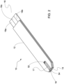
- FIG. 2 is a perspective view of a biosensor 10.
- the biosensor 10 has a body 12, a fluid sampling end 14, an electrical contact end 16, and a vent opening 52.
- a notch 54 is disposed at the fluid sampling end 14 to facilitate loading of the fluid sample into the sample chamber 17.
- the fluid sampling end 14 includes a sample chamber 17 between a sample inlet 18 and the vent opening 52.
- the electrical contact end 16 has three discrete conductive contacts 16a, 16b, and 16c.
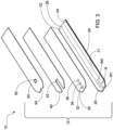
- FIG. 3 is an exploded view of the biosensor 10.
- the body 12 is composed of a substrate 20, an optional reagent holding layer 30, a channel forming layer 40, and a cover 50.
- the layers of the body 12 are generally made of plastics such as polyvinyl chloride, polycarbonate, polysulfone, nylon, polyurethane, cellulose nitrate, cellulose propionate, cellulose acetate, cellulose acetate butyrate, polyester, polyimide, polypropylene, polyethylene and polystyrene.
- polystyrene resins include: nylon, polyesters, copolyesters, polyethylene, polypropylene, polyamides; polystyrene, polystyrene copolymers, styrene acrylonitrile copolymers, acrylonitrile butadiene styrene copolymers, poly(methylmethacrylate), acrylic copolymers, poly(ether-im ides); polyphenylene oxides or poly(phenylene oxide)/polystyrene blends, polystyrene resins; polyphenylene sulfides; polyphenylene sulfide/sulfones; poly(ester-carbonates); polycarbonates; polysulfones; polysulfone ethers; and poly(ether-ketones); or mixtures of any of the other foregoing polymers. These materials may be either flexible or rigid, and should be generally non-conductive and chemically inert to the contemplated chemical reactions described herein.
- the substrate 20 has a metal film 21 on which are delineated three electrodes 22, 24 and 26.
- the electrodes 22, 24, 26 may be formed by scribing or scoring the metal film 21, or by silk-screening electrodes 22, 24, 26 onto the substrate 20. Scribing or scoring of the metal film 21 may be done by mechanically scribing the metal film 21 sufficiently to create the three independent electrodes 22, 24, 26.
- the preferred scribing or scoring method of the present disclosure is done by using a carbon dioxide laser, a YAG laser or an excimer laser. Alternatively, the metal film is patterned as it is laid down, such that the metal film forms one electrode.
- Yet another method for forming an electrode for a biosensor comprises (a) providing a substrate; (b) providing a target; and (c) physical vapor depositing at least a portion of said substrate with material from said target to thereby form a conductive layer (i.e. electrode) on said substrate.
- Physical vapor deposition techniques include sputter coating (e.g., magnetron sputtering, unbalanced magnetron sputtering, facing targets sputtering, or the like), thermal evaporation, electron beam evaporation, laser ablation, arc vaporization, co-evaporation, ion plating, or the like. As illustrated here, three different films would be deposited to form the three electrodes 22, 24, 26.
- the reagent holding layer 30 can be used when liquid reagents are desired to be used.
- the reagent holding layer 30 has three reagent holding openings 32, 34 and 36.
- the reagent holding opening 32 exposes a portion of the electrode 22
- the reagent holding opening 34 exposes a portion of the electrode 24
- the reagent holding opening 36 exposes a portion of the electrode 26 creating reagent holding wells.
- This layer 30 is used to hold a sufficient quantity of chemical reagents in liquid form and to promote capillary action through the sample chamber of the sensor.
- the reagent holding layer 30 may be made from a plastic sheet and may be coated with a pressure sensitive adhesive, a photopolymer, ultrasonically-bonded to substrate 20, or silk-screened onto the substrate 20.
- the channel forming layer 40 has a U-shaped cutout 42 located at the fluid sampling end 14.
- the length of the cutout 42 is such that when the channel forming layer 40 is laminated to reagent holding layer 30, electrode areas W and R are within the space defined by the cutout 42.
- the length, width and thickness of the U-shaped cutout 42 define the capillary channel volume.
- the three reagent holding openings 32, 34, 36 define electrode areas W1, W2, and R, respectively, and hold chemical reagents forming two working electrodes and one reference electrode.
- the electrode areas are loaded with the reagent mixtures.
- the reagent mixtures for the working electrode areas 32, 34, 36 are a mixture of enzymes and redox mediators with optional polymers, surfactants, and buffers.
- a reference reagent matrix may be loaded in electrode area R that is similar to the reagent mixture of the working electrodes. It is contemplated that W1 and W2 use different enzymes / mediators, which can be used to check each other. Embodiments are also contemplated that have only one working electrode, which may be simpler to manufacture.
- the chemical reagents can be used to form a reagent layer in the form of a dried solid film on the electrode areas W1, W2, R.
- the reagent holding layer 30 is not needed.
- electrode area R must be loaded with a redox reagent or mediator to make the reference electrode function.
- the reference reagent mixture preferably contains either oxidized or a mixture of an oxidized and reduced form of redox mediators, at least one binder, a surfactant and an antioxidant (if a reduced form of redox mediator is used) and a bulking agent.
- the reference electrode could be also loaded with an Ag/AgCI layer (e.g. by applying Ag/AgCI ink or by sputter-coating an Ag or Ag/AgCI layer) or other reference electrode materials that do not require a redox mediator to function properly.
- the size of the reagent holding openings is desirably as small as possible while still being capable of holding sufficient chemical reagent to function properly.
- the reagent holding openings are round and have a preferred diameter of 0.03 in. (0.76 mm).
- the three reagent holding openings 32, 34, 36 are aligned with each other and are spaced 0.025 in. (0.625 mm) from each other.
- the circular reagent holding openings are for illustrative purposes only and it should be understood that the shape of the reagent holding openings is not critical.
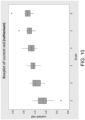
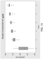
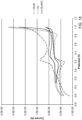
- a fluid sample When a fluid sample is applied to a single strip of the present disclosure, the fluid sample enters the channel through the sampling end aperture and flows over W1, W2 and R and stops at the threshold of the vent opening. Chronoamperometry (i-t curve) can be used to measure the current response of the biosensor. Oxygen concentration (p02) can be controlled. Once a blood sample enters the strip, a potential of 0.3-0.5 volts is applied across the working electrodes and the reference electrode. The glucose concentration of the blood sample can then be measured.
- a sensor of the present disclosure may also utilize coulometric, potentiometric, voltammetric, and other electrochemical techniques to determine the concentration of an analyte in a sample.
- FIG. 4 is a flowchart that illustrates an exemplary method 100 of creating a biosensor with an electrode made from a multi-layer stack.
- the method 100 includes the steps of: forming multiple layers on the surface of a substrate, the multiple layers including at least one conductive electrode layer (E) and at least one base layer (B)on a surface of a substrate, in which the conductive electrode layer includes ruthenium or nickel (Step 120); forming a reaction chamber in the substrate in which the reaction chamber contacts the conductive electrode layer (Step 140); forming a reagent layer on the conductive electrode layer to form a working electrode (Step 160); and forming a second electrode on the substrate (Step 180).
- an electrically conductive electrode layer and an electrically conductive base layer are formed on a surface of a substrate in which the conductive electrode layer includes ruthenium or nickel.
- the base layer directly contacts the substrate, or put another way the base layer is located between the electrode layer and the substrate.
- the electrode layer directly contacts the substrate, or in other words the electrode layer is located between the base layer and the substrate.
- the layers of the multi-layer stack are sputtered onto a surface of a substrate.
- a conductive base layer can be deposited onto the substrate surface by using fast ions to eject particles of the metal from a conductive material source due to contact of the metal source by energetic particles.
- the base conductive layer can be deposited by evaporation of a metal in a vacuum environment.
- the electrode layer can then be deposited onto the base layer using similar techniques.
- the multi-layer stack can be used to form a single electrode, or can be shaped or patterned to form two or more electrodes.
- the multi-layer stack includes a base layer and an electrode layer.
- the base layer can be made from a plurality of sublayers, each sublayer being made from an electrically conductive metal that does not contain ruthenium.
- the electrode layer can be made from a set of sublayers, one containing the ruthenium metal or alloy, and the other containing carbon.
- any configuration of layers disclosed herein may be formed at step 120, including but not limited to those depicted in FIGS. 1A-1C .
- a reaction chamber is formed in the substrate in which the reaction chamber contacts the conductive electrode layer.
- the reaction chamber can be formed in the substrate by any method known in the art.
- a reagent layer is formed on the conductive electrode layer of the metal layer stack to form a working electrode.
- the reagent layer can be formed on the conductive electrode layer by any method known in the art. More particularly, the reagent layer contains an enzyme, a coenzyme, and an electron mediator. Specific enzyme/mediator systems are contemplated. In a first system, the enzyme is glucose oxidase (GOD), the coenzyme is flavin adenine dinucleotide (FAD), and the mediator is hexacyanoferrate (II)/hexacyanoferrate.
- GOD glucose oxidase
- FAD flavin adenine dinucleotide
- II hexacyanoferrate
- the enzyme is glucose dehydrogenase (GDH)
- the coenzyme is pyrroloquinoline quinone (PQQ)
- the mediator is hexacyanoferrate (II)/hexacyanoferrate.
- the enzyme is GDH
- the coenzyme is PQQ
- the mediator is quinoneamine / phenylenediamine.
- a second electrode is formed on the substrate.
- the second electrode can be formed as described in Step 120.
- the electrode layer can be made from a ruthenium-containing metal alloy.
- the ruthenium-containing metal alloy itself can be a binary, ternary, or quaternary alloy of suitable metals.
- the ruthenium-containing metal alloy is a metal alloy containing ruthenium (Ru) in combination with one or more additional alloying element(s).
- the alloy may contain from 5 atomic percent (at%) to 95 at% ruthenium, including 50 at% or greater ruthenium; 5 at% to 45 at% ruthenium; from 50 at% to 95 at% ruthenium; 55 at% to 95 at% ruthenium; 50 at% to 65 at% ruthenium; from 50 at% to 60 at%; 55 at% to 75 at% ruthenium; from 60 at% to 70 at%; 65 at% to 85 at% ruthenium; from 70 at% to 80 at%; 75 at% to 95 at% ruthenium; from 80 at% to 90 at%; or 85 at% to 95 at% ruthenium.
- the metal alloys containing ruthenium (Ru) are formed in combination with one or more elements such as aluminum (Al), chromium (Cr), copper (Cu), nickel (Ni), rhenium (Re), or tungsten (W).
- the alloy may contain from 5 at% to 95 at% of these additional alloying element(s), including 55 at% to 95 at%; 5 at% to 50 at%; 35 at% to 50 at%; from 40 at% to 50 at%; 25 at% to 45 at%; from 30 at% to 40 at%; 15 at% to 35 at%; from 20 at% to 30 at%; 5 at% to 25 at%; from 10 at% to 20 at%; or 5 at% to 15 at%; or from 0 at% to 10 at% of the additional alloying element(s).
- the electrode layer of the electrode used in the biosensor can be made from ruthenium metal (i.e. 100 at% ruthenium), or a metal alloy that contains a high content of ruthenium, such as from 95 at% to less than 100 at% ruthenium.
- the high content ruthenium metal alloy itself can be a binary, ternary, or quaternary alloy of suitable metals.
- the alloy is a metal alloy containing ruthenium (Ru) in combination with one or more additional alloying element(s).
- the alloy may contain from 95 atomic percent (at%) to less than 100 at% ruthenium, including 95 at% to 96 at% ruthenium; from 96 at% to 97 at% ruthenium; 97 at% to 98 at% ruthenium; or 98 at% to 99 at% ruthenium.
- the ruthenium-containing alloys contain a high content of ruthenium (Ru) in combination with one or more elements such as aluminum (Al), chromium (Cr), copper (Cu), nickel (Ni), rhenium (Re), or tungsten (W).
- the alloy may contain from greater than zero at% to 5 at% of these additional alloying element(s), including 1 at% to 2 at%; 2 at% to 3 at%; 3 at% to 4 at%; and from 4 at% to 5 at% of the additional alloying element(s).
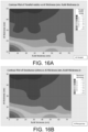
- the metal layer stack may be formed using a cluster (i.e., co-sputtering) system with the substrate rotation disabled to allow a range of compositions over the wafer area.
- a cluster i.e., co-sputtering
- the substrate rotation disabled to allow a range of compositions over the wafer area.
- the ruthenium-containing alloy is a binary metal alloy containing ruthenium in combination with either chromium or tungsten.
- the ruthenium-containing metal alloy is a binary alloy combining ruthenium (Ru) with aluminum (Al).
- the ruthenium-containing metal alloy is a binary alloy combining ruthenium (Ru) with nickel (Ni).
- the ruthenium-containing metal alloy includes ruthenium (Ru) with rhenium (Re).
- the ruthenium-containing alloy is a binary metal alloy containing ruthenium in combination with either chromium or tungsten.
- binary alloys may comprise 55 at% to 85 at% ruthenium, or 55 at% to 65 at% ruthenium, or 75 at% to 85 at%. The remainder of these binary alloys is chromium or tungsten.
- the ruthenium-containing metal alloy is a binary alloy combining ruthenium (Ru) with aluminum (Al).
- the alloy may contain from 5 at% to 45 at% ruthenium, or from 55 at% to 95 at% ruthenium, with the remainder being aluminum.
- the alloy may contain 60 at% to 70 at% ruthenium and 30 at% to 40 at% aluminum.
- the ruthenium-containing metal alloy is a binary alloy combining ruthenium (Ru) with nickel (Ni).
- the alloy may contain from 55 at% to 95 at% ruthenium and from 5 at% to 45 at% nickel.
- the ruthenium-containing metal alloy includes ruthenium (Ru) with rhenium (Re).
- the alloy may contain from 55 at% to 95 at% ruthenium and from 5 at% to 45 at% rhenium.
- the electrode layer can also be made from a nickel -containing metal alloy.
- the nickel-containing metal alloy itself can be a binary, ternary, or quaternary alloy of suitable metals.
- the alloy is a metal alloy containing nickel (Ni) in combination with one or more additional alloying element(s).
- the alloy may contain from 55 atomic percent (at%) to 95 at% nickel; 55 at% to 65 at% nickel; from 55 at% to 60 at%; 55 at% to 75 at% nickel; from 60 at% to 70 at%; 65 at% to 85 at% nickel; from 70 at% to 80 at%; 75 at% to 95 at% nickel; from 80 at% to 90 at%; or 85 at% to 95 at% nickel.
- the alloys used herein are metal alloys containing nickel (Ni) in combination with one or more elements such as aluminum (Al), gold (Au), chromium (Cr), copper (Cu), molybdenum (Mo), palladium (Pd), ruthenium (Ru), tantalum (Ta), and titanium (Ti).
- Ni nickel
- elements such as aluminum (Al), gold (Au), chromium (Cr), copper (Cu), molybdenum (Mo), palladium (Pd), ruthenium (Ru), tantalum (Ta), and titanium (Ti).
- the alloy may contain from 5 at% to 45 at% of these additional alloying element(s), including 35 at% to 45 at%; from 40 at% to 45 at%; 25 at% to 45 at%; from 30 at% to 40 at%; 15 at% to 35 at%; from 20 at% to 30 at%; 5 at% to 25 at%; from 10 at% to 20 at%; or 5 at% to 15 at%; or from 0 at% to 10 at% of the additional alloying element(s).
- the alloy may be formed using a cluster (i.e., co-sputtering) system with the substrate rotation disabled to allow a range of compositions over the wafer area.
- a cluster i.e., co-sputtering
- the substrate rotation disabled to allow a range of compositions over the wafer area.
- the alloy is a metal alloy containing nickel (Ni) in combination with one or more additional alloying element(s).
- the alloy may contain from 20 atomic percent (at%) to 95 at% nickel.
- the one or more additional alloying element(s) can include aluminum, ruthenium, tantalum, and titanium.
- the alloy may contain from 5 at% to 80 at% of aluminum, ruthenium, tantalum, and titanium.
- the alloy is a binary metal alloy containing nickel in combination with either aluminum, chromium, or ruthenium.
- These binary alloys may comprise 55 at% to 95 at% nickel, or 55 at% to 85 at% nickel, or 75 at% to 85 at% nickel. The remainder of these binary alloys is aluminum, chromium, or ruthenium.
- the alloy is a binary metal alloy containing nickel in combination with either aluminum, copper, chromium, tantalum, or titanium.
- These binary alloys may comprise 55 at% to 95 at% nickel, or 55 at% to 85 at% nickel, or 75 at% to 85 at% nickel. The remainder of these binary alloys is aluminum, copper, chromium, tantalum, or titanium.
- the alloy is a binary metal alloy containing nickel in combination with either aluminum, chromium, or titanium.
- These binary alloys may comprise 55 at% to 95 at% nickel, or 55 at% to 85 at% nickel, or 75 at% to 85 at% nickel. The remainder of these binary alloys is aluminum, chromium, or titanium.
- the metal alloy is a binary alloy combining nickel (Ru) with ruthenium (Ru).
- the alloy may contain from 45 at% to 95 at% ruthenium and from 5 at% to 55 at% ruthenium.
- the alloy is a ternary alloy combining 20 at% to 55 at% nickel with 20 at% to 30 at% titanium and 20 at% to 30 at% tantalum.
- the alloy is a ternary alloy combining 20 at% to 55 at% nickel with 20 at% to 30 at% aluminum and 20 at% to 30 at% ruthenium.
- the metal alloys used in either the base layer or the electrode layer may comprise incidental impurities.
- incident impurities refer to any impurities that naturally occur in the ore used to produce the metal alloys or that are inadvertently added during the production process.
- the resulting electrode(s) formed from the combination of a base layer and an electrode layer desirably exhibit improved physical and electrical properties, due to the use of ruthenium or nickel, either as a metal or as a metal alloy.
- One improved property is the thickness of the electrode, which can be very thin.
- the electrode can have a thickness of 200 angstroms to 200 nanometers, including from 10 nanometers to 100 nanometers.
- Another improved property is the electrical conductivity of the electrode, which can be less than 100 ohms/square (Q/sq) at the desired thickness.
- the biosensor may also exhibit improved stability, as measured by electrochemical response stability over time when exposed to humidity and temperature variations, or as measured by changes in adhesion and/or abrasion differences when exposed to the reagent.
- Other desirable properties can include physical contact durability, lowered contact resistance for lowered/more consistent bias response, and/or better cohesion for finer line formation in circuitry.
- the resulting electrode(s) formed from the ruthenium-based or nickel-based alloy can be produced at a lower cost compared to more expensive metals such as gold.
- the electrode can be formed by physical vapor deposition. This generally describes the coating of the substrate with the material from a target to form each layer of the electrode.
- physical vapor deposition shall denote depositing thin-films by providing for the condensation of vaporized material onto a substrate.
- the physical vapor deposited coating may be performed with any type of physical vapor deposition process previously described, i.e., sputter coating, thermal evaporation, electron beam evaporation, laser ablation, arc vaporization, co-evaporation, ion plating, or the like.
- the physical vapor depositing step will be performed via a sputtering process, in which the substrate is coated with a layer by sputtering via a sputtering device.
- the resulting substrate with the multi-layer electrode coated thereon may be used as a biosensor component, which may include a working electrode, a reference electrode, or a counter electrode.
- the resulting thin-film sheet may be cut apart to appropriate size to form a thin-film electrode upon a substrate.
- the biosensor components can be formed from the thin-film sheet by etching, such as chemical or laser etching.
- the biosensor components can be formed using a patterned mask, which is laid on the substrate, and the conductive layers are physical vapor deposited thereover to form the biosensor component.
- the biosensor components may be created via a roll-to-roll physical vapor deposition process that includes roll-to-roll magnetron sputtering.
- a substrate sheet comprising a polymer film made of PET (polyethylene terephthalate) with a thickness ranging from 25 pm to 250 pm and width of 33.02 cm may be sputtered using a 77.50 cm wide web roll-to-roll magnetron sputter coater.
- a single or a dual target configuration can be employed to deposit multiple layers of metal or metal alloys.
- a target comprised of a non-noble metal alloy plate can be used to form the base layer.
- a vacuum chamber of the sputter coater can be pumped down to base pressure of at least 10 -5 Torr using a diffusion and mechanical pump combination.
- a combination of a mechanical pump, a turbo pump, a cryo pump, and/or an oil diffusion pump may be used.
- Magnetron sputtering cathodes housing the non-noble metal alloy targets having a generally rectangular shape of 15.24 cm x 30.48 cm can be energized using 2 KW power supplies (such as offered from Advanced Energy Inc.).
- An argon gas flow into the vacuum chamber can be controlled (such as via a MKS model 1179A flow controller) to set a sputtering pressure between 0.4 to 1 Pa (3 to 10 mTorr) for use during the sputtering process.
- a thickness and sheet resistance of each sputtered conductive layer can be efficiently controlled in-situ by controlling the roll-to-roll web speeds, i.e., controlling the speed of the substrate sheet as it travels through the vacuum chamber during sputtering.
- the web speed can be set to between 0.1 to 3.5 meters per minute and sputtering power density of between 2 to 8 Watts per square cm.
- sputtered conductive layer of Composition A3 may be formed having a measured thickness value of 25 nm and a sheet resistance of 45 ohms per square.
- Cyclic Voltammetry (CV) analysis was selected to detect changes in performance, with a baseline performance based on pure gold electrodes.
- the CV test method measured faradaic current generated by the reduction of oxidation of substances near the electrode, including cathodic peak current (Ipc), anodic peak current (Ipa), cathodic peak potential (Epc), and anodic peak potential (Epa).
- Ipc cathodic peak current
- Ipa anodic peak current
- Epc cathodic peak potential
- Epa X-ray powder diffraction
- the test electrode samples were serialized within wafers to identify sample position, as well as serialized for wafer lot identification number.
- the initial test included at least 10 samples per wafer with locations distributed across the wafer.
- the Cyclic Voltammetry (CV) test parameters are summarized in Table 1 below: Table 1.
- Initial CV test parameter (screening) summary Test Parameter Description Value Notes H2SO4 conc. Sulfuric acid cleaning solution concentration 0.1 M Used with potential scan to initially clean electrode of contamination.
- KCl conc Potassium Chloride electrolyte concentration 0.1 M - K4Fe(CN)6 conc.
- Potassium ferrocyanide analyte concentration 1 mM - Sample volume Volume of tested solution 20 pL - Waveform / Scan range Potential range -0.5 V to 0.3 V - Scan rate Rate of potential change 50 mV/s Test repeats # of repeated scans (same electrode) 6 or greater Can abort scans after 3 if no redox response detected
- Electrodes were singulated in strips using a paper cutter, then manually singulated from the strips with scissors. The electrodes were placed in a test fixture and connected to a BASi potentiostat and analyzer. Cyclic voltammetry (CV) was performed using 1 nM of K4Fe(CN)6 concentration in 0.1 M KCI. Peak current (IP), Ipc, Ipa, Epc, and Epa were recorded as well as a qualitative assessment.
- CV Cyclic voltammetry
- Baseline variability was chosen to be based on gold electrodes for subsequent material response evaluation.
- the cyclic voltammetry of six randomly picked gold electrodes from the same sputtered wafer were equivalent enough for establishment of baseline electrode variability.
- the electrodes showed consistent characteristics at different locations on the wafer, and multiple scans indicated stabilization of the response over the multiple scans.
- the cyclic voltammetry using the gold electrode was a symmetrical cycle which suggested that the electrode was able to be used for the electrochemical test. After the first three scans, scans 4-6 demonstrate that the cyclic voltammetry response was stable and repeatable.
- T-Test was performed between the current redox and the current oxidation for the baseline gold electrodes to test the difference between the two samples.
- the results of the T-Test are shown below in Table 3: Table 3.
- Two-Sample T-Test and CI current red and current ox (gold)
- Two-sample T for current red vs current ox N Mean StDev SE
- Difference p (current red) - p (current ox)
- ruthenium mean or variance differences were based on the established gold baseline variability discussed above. Based on electrode pass/fail criteria of redox response detected with 1mM potassium ferricyanide analyte between - 500 to 500 mV, ruthenium-based alloys demonstrated good stability and electrochemical response compared with the baseline gold electrodes. The ruthenium redox response was stable and repeatable in the range tested. As demonstrated by FIG.
- ruthenium results in an increasing concave down stabilization pattern which compares favorably with the gold electrode baseline.
- nickel mean or variance differences were also based on the established gold baseline variability discussed above. Based on electrode pass/fail criteria of redox response detected with 1mM potassium ferricyanide analyte between -500 to 500 mV, pure nickel demonstrated good stability and electrochemical response compared with the baseline gold electrodes. The nickel redox response was stable and reversible in the range tested. As demonstrated by the results of the T-Test in Table 4B below, the amount of non-faradaic (i.e., background) current appeared to be similar to gold electrode systems, since Ipa/lpc 1 when isolating the 3rd scan in the analysis, indicating good reversibility.
- anodic and cathodic peak separation mean is 80mV, which is equivalent to the established gold baseline.
- the cyclic voltammetry was mostly a symmetrical cycle, which suggests that the electrode was able to be used for the electrochemical test. Table 4B.
- Example 2 gold (Au), palladium (Pd), ruthenium (Ru) and nickel (Ni) were initially compared against the Nernstian ideal of 59 mV, which is desirable and indicative of electron transfer kinetics that are beneficial for amperometric sensing applications. As shown in FIG. 14 , gold, palladium, ruthenium, and nickel all exhibit redox reactions in the system evaluated. Generally, peak potential separations were close to the Nernstian ideal of 59 mV. Ruthenium and ruthenium-based alloys show good properties in regards to the ferro/ferricyanide mediator system, with improved maneuverability and electrochemical stability in the potential range evaluated over nickel.
- Binary ruthenium alloys evaluated for performance and cost are shown in Table 5 below: Table 5.
- Binary nickel alloys evaluated for performance and cost are shown in Table 6 below: Table 6.
- Table 7 shows pure gold (Au) and palladium (Pd) metals evaluated for performance and cost: Table 7. Pure metals average current response (units in pA, 1 mM K4Fe(CN)6 analyte) Metal 90-100 at% Performance Notes Au 1.122 Stable, low background, reversible Pd 0.7217 Strong initial response, degrades after multiple scans
- Ruthenium-based alloys RuW and RuCr have shown good response relative to gold with compositions of greater than 50 at% ruthenium, as presented above and as shown in FIG. 15 .
- Nickel-based alloys NiCr, NiTi, and NiAl have shown good response relative to gold with compositions of 80 at% nickel or greater, as presented above and as shown in FIG. 15 .
- non-precious metal alloys including nickel and/or ruthenium (note that though ruthenium may be classified as a precious metal, in this context it qualifies as a candidate based on cost), advantageously comparable responses and performance to expensive pure metals such as gold and palladium.
- these non-precious metal alloys may further be optimized for corrosion resistance through the addition of titanium (Ti), tantalum (Ta), and chromium (Cr).
- these non-precious metal alloys may further be optimized for cost through the addition of nickel (Ni), titanium (Ti), molybdenum (Mo), aluminum (Al), tin (Sn), etc.
- Particular alloys that have responses comparable to gold and exceeding palladium or NiCr performance include RuW (Ru > 50%) and RuCr (Ru > 50%).
- Particular alloys that have responses comparable to NiCr include NiTi (Ni > 80 at%), NiAl (Ni > 80 at%), or NiRu (Ni > 50at %).
- ternary alloys have been tested with the same combination of the above elements (e.g., RuCrW and RuAlNi). These ternary alloys have advantages when designing for certain material properties (e.g., ductility, corrosion resistance, heat resistance).
- a RuW top layer was deposited on aluminum or silver base layers each of varying thickness. The resistance of each sample (run) was measured. The results are shown in Table 10 below. Table 10. Run Al Thickness (nm) RuW thickness (nm) Resistance (ohms/sq) Al Strike 50 1.7 RuW Strike 30 53.8 1 30 10 3 2 30 30 2.8 3 50 10 1.7 4 50 30 1.6 Target 1.9 ohms 1.6 Target 1.9 ohms 1.8 Run Ag Thickness RuW thickness (nm) Resistance (ohms/sq) Ag Strike 50 0.84 RuW Strike 30 9.98 1 3 10 1.7 2 30 30 1.7 3 50 10 0.9 4 50 30 1 Target 1.9 ohms 10 1.8 Target 1.9 ohms 30 1.9
- a stacked material configuration should behave as parallel resistors, i.e. (1/Rt - 1/Ri + 1/R2 ... 1/Rn).
- the parallel resistor model is confirmed experimentally below, and is an accurate predictor of sheet resistance in the range tested.
- a contour plot of resistance vs aluminum thickness and RuW thickness is shown in FIG. 16A for the Al resistor model and in FIG. 16B for the measured response.
- FIG. 17 is a cyclic voltammetry graph showing Cr/RuW over a range of thicknesses (the same as in Table 15). Electrode performance in 1mM ferro/ferricyanide solution is similar to Au. Table 15.
- FIG. 18 is a cyclic voltammetry graph showing electrodes with an electrode layer made of Au, RuW, and RuW/C. The addition of carbon increased the potential window of the electrode.
- the electrodes of the present disclosure have been described as being useful in biosensor/electrode type applications. However, it should be understood they may be useful in any sensor article or device that, as a result of a chemical interaction or process between an analyte and the sensor, transforms chemical or biochemical information of a quantitative or qualitative type into an analytically useful signal.
- the multi-layer electrodes disclosed herein may be included in articles useful in automotive, indoor air quality (IAQ), food, agriculture, medical, water treatment, environmental, industrial safety, utilities (e.g., gas, electric), petrochemical, steel, military, and aerospace applications and markets.
Claims (15)
- Biosensor für das Messen eines Analyts, umfassend:ein Substrat,eine erste Elektrode, die als eine auf dem Substrat angeordnete Referenzelektrode betrieben wird,eine zweite Elektrode, die auf dem Substrat angeordnet ist, undeine Reagenzschicht, die auf der zweiten Elektrode angeordnet ist, um eine Arbeitselektrode zu bilden,wobei die Reagenzschicht ein Enzym und einen Elektronenvermittler umfasst,wobei die erste Elektrode aus einem ersten mehrschichtigen Stapel, der eine erste Basisschicht und eine die erste Basisschicht direkt kontaktierende erste Elektrodenschicht umfasst, ausgebildet ist,wobei die erste Basisschicht ein leitendes Metall, eine leitende Metalllegierung oder Kohlenstoff umfasst,wobei die erste Elektrodenschicht Rutheniummetall, eine Ruthenium-basierte Metalllegierung, Nickelmetall oder eine Nickel-basierte Metalllegierung umfasst,wobei die erste Elektrodenschicht aus anderen Materialien als die erste Basisschicht ausgebildet ist, und wobei die erste Basisschicht eine höhere elektrische Leitfähigkeit aufweist als die erste Elektrodenschicht, undwobei die zweite Elektrode einen zweiten mehrschichtigen Stapel mit dem gleichen Aufbau wie der erste mehrschichtige Stapel umfasst.
- Biosensor nach Anspruch 1, wobei die Ruthenium-basierte Metalllegierung ein erstes Legierungselement umfasst, das aus der Gruppe ausgewählt ist, die aus Aluminium, Chrom, Kupfer, Nickel, Rhenium und Wolfram besteht, oder
wobei die Nickel-basierte Metalllegierung ein erstes Legierungselement umfasst, das aus der Gruppe ausgewählt ist, die aus Aluminium, Gold, Chrom, Kupfer, Molybdän, Palladium, Ruthenium, Tantal und Titan besteht. - Biosensor nach Anspruch 1, wobei die Ruthenium-basierte Metalllegierung von 5 at% bis 95 at%, oder von 5 at% bis 45 at%, oder von 50 at% bis 95 at%, oder von 50 at% bis 65 at%, oder von 55 at% bis 75 at%, oder von 65 at% bis 85 at%, oder von 75 at% bis 95 at%, oder von 85 at% bis 95 at%, oder von 95 at% bis weniger als 100 at% Ruthenium enthält.
- Biosensor nach Anspruch 3, wobei die Ruthenium-basierte Metalllegierung eine binäre Legierung ist und aus Ruthenium und einem ersten Legierungselement besteht, wobei das erste Legierungselement aus der Gruppe ausgewählt ist, die aus Aluminium, Chrom, Kupfer, Nickel, Rhenium und Wolfram besteht, oder
wobei die Ruthenium-basierte Metalllegierung eine ternäre Legierung ist und aus Ruthenium, dem ersten Legierungselement und einem zweiten Legierungselement besteht, wobei das erste Legierungselement und das zweite Legierungselement jeweils aus der Gruppe ausgewählt sind, die aus Aluminium, Chrom, Kupfer, Nickel, Rhenium und Wolfram besteht. - Biosensor nach Anspruch 1, wobei die Ruthenium-basierte Metalllegierung eine binäre Legierung ist, die aus (a) 55 at% oder mehr Ruthenium und (b) 15 at% oder mehr Chrom oder Wolfram besteht, oderwobei die Ruthenium-basierte Metalllegierung eine binäre Legierung ist, die aus (a) 60 at% bis 70 at% Ruthenium und (b) 30 at% bis 40 at% Aluminium besteht, oderwobei die Ruthenium-basierte Metalllegierung eine binäre Legierung ist, die aus (a) 5 at% bis 25 at% Ruthenium und (b) 75 at% bis 95 at% Nickel besteht.
- Biosensor nach Anspruch 1, wobei die Ruthenium-basierte Metalllegierung eine ternäre Legierung ist, die aus (a) 20 at% bis 55 at% Ruthenium und (b) 45 at% bis 80 at% einer Kombination aus Nickel und Aluminium besteht, oder
wobei die Ruthenium-basierte Metalllegierung eine ternäre Legierung ist, die aus (a) 20 at% bis 55 at% Ruthenium und (b) 45 at% bis 80 at% einer Kombination aus Chrom und Wolfram besteht. - Biosensor nach Anspruch 1, wobei die Nickel-basierte Metalllegierung von 20 at% bis 95 at%, oder von 55 at% bis 95 at%, oder von 55 at% bis 65 at%, oder von 55 at% bis 60 at%, oder von 55 at% bis 75 at%, oder von 60 at% bis 70 at%, oder von 65 at% bis 85 at%, oder von 70 at% bis 80 at%, oder von 75 at% bis 95 at% oder von 80 at% bis 90 at%, oder von 85 at% bis 95 at% Nickel enthält.
- Biosensor nach Anspruch 7, wobei die Nickel-basierte Metalllegierung eine binäre Legierung ist und aus Nickel und einem ersten Legierungselement besteht und wobei die Nickel-basierte Metalllegierung von 5 at% bis 80 at% des ersten Legierungselements enthält und das erste Legierungselement aus der Gruppe ausgewählt ist, die aus Aluminium, Ruthenium, Tantal und Titan besteht.
- Biosensor nach Anspruch 7, wobei die Nickel-basierte Metalllegierung eine ternäre Legierung ist und aus Nickel, einem ersten Legierungselement und einem zweiten Legierungselement besteht, wobei das erste Legierungselement und das zweite Legierungselement jeweils aus der Gruppe ausgewählt sind, die aus Aluminium, Ruthenium, Tantal und Titan besteht, und wobei das erste Legierungselement und das zweite Legierungselement gemeinsam von 5 at% bis 80 at% der Legierung ausmachen.
- Biosensor nach Anspruch 7, wobei die Nickel-basierte Metalllegierung eine binäre Legierung ist, die aus (a) 55 at% bis 95 at% Nickel und (b) 5 at% bis 45 at% Aluminium, Kupfer, Chrom, Tantal, Ruthenium oder Titan besteht, oder wobei die Nickel-basierte Metalllegierung eine binäre Legierung ist, die aus (a) 45 at% bis 95 at% Nickel und (b) 5 at% bis 55 at% Ruthenium besteht.
- Biosensor nach Anspruch 7, wobei die Nickel-basierte Metalllegierung eine ternäre Legierung ist, die aus (a) 20 at% bis 55 at% Nickel und (b) entweder (i) 20 at% bis 30 at% Titan und 20 at% bis 30 at% Tantal oder (ii) 20 at% bis 30 at% Aluminium und 20 at% bis 30 at% Ruthenium besteht.
- Biosensor nach Anspruch 1, wobei die erste Basisschicht eine Dicke von 100 Angström bis 100 Nanometer aufweist und wobei die erste Elektrodenschicht eine Dicke von 10 Nanometer bis 100 Nanometer aufweist.
- Biosensor nach Anspruch 1, der weiterhin eine zweite Basisschicht umfasst, wobei die erste Elektrodenschicht zwischen der ersten Basisschicht und der zweiten Basisschicht angeordnet ist.
- Biosensor nach Anspruch 1, wobei der erste mehrschichtige Stapel weiterhin eine zweite Elektrodenschicht umfasst, wobei die erste Basisschicht zwischen der ersten Elektrodenschicht und der zweiten Elektrodenschicht angeordnet ist.
- Artikel, der den Biosensor nach einem der Ansprüche 1 bis 14 umfasst.
Priority Applications (1)
| Application Number | Priority Date | Filing Date | Title |
|---|---|---|---|
| EP23218289.9A EP4335942A2 (de) | 2018-04-18 | 2019-04-18 | Elektroden für biosensoren |
Applications Claiming Priority (2)
| Application Number | Priority Date | Filing Date | Title |
|---|---|---|---|
| US201862659407P | 2018-04-18 | 2018-04-18 | |
| PCT/US2019/028073 WO2019204578A1 (en) | 2018-04-18 | 2019-04-18 | Electrodes for biosensors |
Related Child Applications (1)
| Application Number | Title | Priority Date | Filing Date |
|---|---|---|---|
| EP23218289.9A Division EP4335942A2 (de) | 2018-04-18 | 2019-04-18 | Elektroden für biosensoren |
Publications (2)
| Publication Number | Publication Date |
|---|---|
| EP3781699A1 EP3781699A1 (de) | 2021-02-24 |
| EP3781699B1 true EP3781699B1 (de) | 2024-01-17 |
Family
ID=66429603
Family Applications (2)
| Application Number | Title | Priority Date | Filing Date |
|---|---|---|---|
| EP19722378.7A Active EP3781699B1 (de) | 2018-04-18 | 2019-04-18 | Elektroden für biosensoren |
| EP23218289.9A Pending EP4335942A2 (de) | 2018-04-18 | 2019-04-18 | Elektroden für biosensoren |
Family Applications After (1)
| Application Number | Title | Priority Date | Filing Date |
|---|---|---|---|
| EP23218289.9A Pending EP4335942A2 (de) | 2018-04-18 | 2019-04-18 | Elektroden für biosensoren |
Country Status (4)
| Country | Link |
|---|---|
| US (3) | US11499206B2 (de) |
| EP (2) | EP3781699B1 (de) |
| CN (1) | CN112513284A (de) |
| WO (1) | WO2019204578A1 (de) |
Families Citing this family (3)
| Publication number | Priority date | Publication date | Assignee | Title |
|---|---|---|---|---|
| EP3885761A1 (de) * | 2020-03-27 | 2021-09-29 | ARKRAY, Inc. | Biosensor und messverfahren damit |
| US20220042189A1 (en) * | 2020-08-05 | 2022-02-10 | Battelle Energy Alliance,Llc | Anodes comprising transition metal and platinum group metal as alloys, and related methods and systems |
| CN114797843A (zh) * | 2022-03-29 | 2022-07-29 | 杭州未名信科科技有限公司 | 一种碳担载的金属纳米团簇催化剂及其制备方法和应用 |
Family Cites Families (9)
| Publication number | Priority date | Publication date | Assignee | Title |
|---|---|---|---|---|
| US4630815A (en) | 1985-12-11 | 1986-12-23 | Ncr Corporation | Quick releasing, pinch roller mechanism |
| DE10027651C2 (de) * | 2000-06-03 | 2002-11-28 | Bosch Gmbh Robert | Elektrode, Verfahren zu deren Herstellung und Zündkerze mit einer derartigen Elektrode |
| US8389860B2 (en) | 2007-12-03 | 2013-03-05 | Nippon Steel Materials Co., Ltd. | Bonding wire for semiconductor devices |
| ITMI20091621A1 (it) | 2009-09-23 | 2011-03-24 | Industrie De Nora Spa | Elettrodo per processi elettrolitici con struttura cristallina controllata |
| KR20120049723A (ko) * | 2010-11-09 | 2012-05-17 | 쓰리엠 이노베이티브 프로퍼티즈 캄파니 | 전기화학적 바이오 센서용 전극 스트립 및 그 제조방법 |
| EP2518497A1 (de) * | 2011-04-29 | 2012-10-31 | Roche Diagnostics GmbH | Elektrochemisches Sensorelement für Körperflüssigkeiten und Herstellungsverfahren dafür |
| KR101308159B1 (ko) | 2011-11-01 | 2013-10-15 | 성균관대학교산학협력단 | 고표면적 분말의 형성 방법 |
| EP2816141B1 (de) | 2012-03-19 | 2016-08-03 | Asahi Kasei Kabushiki Kaisha | Elektrolysezelle und elektrolysetank |
| US10808273B2 (en) * | 2015-12-23 | 2020-10-20 | Materion Corporation | Nickel alloys for biosensors |
-
2019
- 2019-04-18 US US17/045,364 patent/US11499206B2/en active Active
- 2019-04-18 WO PCT/US2019/028073 patent/WO2019204578A1/en unknown
- 2019-04-18 EP EP19722378.7A patent/EP3781699B1/de active Active
- 2019-04-18 CN CN201980032682.5A patent/CN112513284A/zh active Pending
- 2019-04-18 EP EP23218289.9A patent/EP4335942A2/de active Pending
-
2022
- 2022-06-28 US US17/851,677 patent/US11685969B2/en active Active
-
2023
- 2023-05-10 US US18/314,917 patent/US20230340641A1/en active Pending
Also Published As
| Publication number | Publication date |
|---|---|
| WO2019204578A1 (en) | 2019-10-24 |
| EP3781699A1 (de) | 2021-02-24 |
| US20220349028A1 (en) | 2022-11-03 |
| EP4335942A2 (de) | 2024-03-13 |
| US20230340641A1 (en) | 2023-10-26 |
| US20210189523A1 (en) | 2021-06-24 |
| CN112513284A (zh) | 2021-03-16 |
| US11499206B2 (en) | 2022-11-15 |
| US11685969B2 (en) | 2023-06-27 |
Similar Documents
| Publication | Publication Date | Title |
|---|---|---|
| US11299761B2 (en) | Nickel alloys for biosensors | |
| US11685969B2 (en) | Electrodes for biosensors | |
| US9506890B2 (en) | Physical vapor deposited biosensor components | |
| EP3512957B1 (de) | Biosensorelektroden hergestellt durch physikalische gasphasenabscheidung | |
| KR102547061B1 (ko) | 물리적 증착에 의해 제조된 바이오센서 전극 | |
| US11480540B2 (en) | Ruthenium alloys for biosensors | |
| KR102451440B1 (ko) | 물리적 증착된 바이오센서 컴포넌트 |
Legal Events
| Date | Code | Title | Description |
|---|---|---|---|
| STAA | Information on the status of an ep patent application or granted ep patent |
Free format text: STATUS: UNKNOWN |
|
| STAA | Information on the status of an ep patent application or granted ep patent |
Free format text: STATUS: THE INTERNATIONAL PUBLICATION HAS BEEN MADE |
|
| PUAI | Public reference made under article 153(3) epc to a published international application that has entered the european phase |
Free format text: ORIGINAL CODE: 0009012 |
|
| STAA | Information on the status of an ep patent application or granted ep patent |
Free format text: STATUS: REQUEST FOR EXAMINATION WAS MADE |
|
| 17P | Request for examination filed |
Effective date: 20201026 |
|
| AK | Designated contracting states |
Kind code of ref document: A1 Designated state(s): AL AT BE BG CH CY CZ DE DK EE ES FI FR GB GR HR HU IE IS IT LI LT LU LV MC MK MT NL NO PL PT RO RS SE SI SK SM TR |
|
| AX | Request for extension of the european patent |
Extension state: BA ME |
|
| DAV | Request for validation of the european patent (deleted) | ||
| DAX | Request for extension of the european patent (deleted) | ||
| STAA | Information on the status of an ep patent application or granted ep patent |
Free format text: STATUS: EXAMINATION IS IN PROGRESS |
|
| 17Q | First examination report despatched |
Effective date: 20211123 |
|
| P01 | Opt-out of the competence of the unified patent court (upc) registered |
Effective date: 20230530 |
|
| GRAP | Despatch of communication of intention to grant a patent |
Free format text: ORIGINAL CODE: EPIDOSNIGR1 |
|
| STAA | Information on the status of an ep patent application or granted ep patent |
Free format text: STATUS: GRANT OF PATENT IS INTENDED |
|
| INTG | Intention to grant announced |
Effective date: 20230926 |
|
| GRAS | Grant fee paid |
Free format text: ORIGINAL CODE: EPIDOSNIGR3 |
|
| GRAA | (expected) grant |
Free format text: ORIGINAL CODE: 0009210 |
|
| STAA | Information on the status of an ep patent application or granted ep patent |
Free format text: STATUS: THE PATENT HAS BEEN GRANTED |
|
| AK | Designated contracting states |
Kind code of ref document: B1 Designated state(s): AL AT BE BG CH CY CZ DE DK EE ES FI FR GB GR HR HU IE IS IT LI LT LU LV MC MK MT NL NO PL PT RO RS SE SI SK SM TR |
|
| REG | Reference to a national code |
Ref country code: GB Ref legal event code: FG4D |
|
| REG | Reference to a national code |
Ref country code: DE Ref legal event code: R096 Ref document number: 602019045194 Country of ref document: DE |
|
| REG | Reference to a national code |
Ref country code: CH Ref legal event code: EP |
|
| REG | Reference to a national code |
Ref country code: IE Ref legal event code: FG4D |
|
| REG | Reference to a national code |
Ref country code: NL Ref legal event code: FP |