EP3781437B1 - Motorhome with a ladder-like vehicle frame - Google Patents
Motorhome with a ladder-like vehicle frame Download PDFInfo
- Publication number
- EP3781437B1 EP3781437B1 EP19733732.2A EP19733732A EP3781437B1 EP 3781437 B1 EP3781437 B1 EP 3781437B1 EP 19733732 A EP19733732 A EP 19733732A EP 3781437 B1 EP3781437 B1 EP 3781437B1
- Authority
- EP
- European Patent Office
- Prior art keywords
- motorhome
- superstructure
- support structure
- floor
- intermediate support
- Prior art date
- Legal status (The legal status is an assumption and is not a legal conclusion. Google has not performed a legal analysis and makes no representation as to the accuracy of the status listed.)
- Active
Links
- 238000009434 installation Methods 0.000 description 13
- 238000010276 construction Methods 0.000 description 6
- 238000003860 storage Methods 0.000 description 4
- 230000005484 gravity Effects 0.000 description 2
- 230000012447 hatching Effects 0.000 description 2
- 238000009413 insulation Methods 0.000 description 2
- 230000008014 freezing Effects 0.000 description 1
- 238000007710 freezing Methods 0.000 description 1
- 239000013505 freshwater Substances 0.000 description 1
- 239000007788 liquid Substances 0.000 description 1
- 230000014759 maintenance of location Effects 0.000 description 1
- 239000002351 wastewater Substances 0.000 description 1
Images
Classifications
-
- B—PERFORMING OPERATIONS; TRANSPORTING
- B60—VEHICLES IN GENERAL
- B60P—VEHICLES ADAPTED FOR LOAD TRANSPORTATION OR TO TRANSPORT, TO CARRY, OR TO COMPRISE SPECIAL LOADS OR OBJECTS
- B60P3/00—Vehicles adapted to transport, to carry or to comprise special loads or objects
- B60P3/32—Vehicles adapted to transport, to carry or to comprise special loads or objects comprising living accommodation for people, e.g. caravans, camping, or like vehicles
- B60P3/34—Vehicles adapted to transport, to carry or to comprise special loads or objects comprising living accommodation for people, e.g. caravans, camping, or like vehicles the living accommodation being expansible, collapsible or capable of rearrangement
-
- B—PERFORMING OPERATIONS; TRANSPORTING
- B62—LAND VEHICLES FOR TRAVELLING OTHERWISE THAN ON RAILS
- B62D—MOTOR VEHICLES; TRAILERS
- B62D21/00—Understructures, i.e. chassis frame on which a vehicle body may be mounted
- B62D21/14—Understructures, i.e. chassis frame on which a vehicle body may be mounted of adjustable length or width
-
- B—PERFORMING OPERATIONS; TRANSPORTING
- B62—LAND VEHICLES FOR TRAVELLING OTHERWISE THAN ON RAILS
- B62D—MOTOR VEHICLES; TRAILERS
- B62D33/00—Superstructures for load-carrying vehicles
- B62D33/04—Enclosed load compartments ; Frameworks for movable panels, tarpaulins or side curtains
- B62D33/042—Enclosed load compartments ; Frameworks for movable panels, tarpaulins or side curtains divided into compartments
-
- B—PERFORMING OPERATIONS; TRANSPORTING
- B62—LAND VEHICLES FOR TRAVELLING OTHERWISE THAN ON RAILS
- B62D—MOTOR VEHICLES; TRAILERS
- B62D33/00—Superstructures for load-carrying vehicles
- B62D33/08—Superstructures for load-carrying vehicles comprising adjustable means
-
- B—PERFORMING OPERATIONS; TRANSPORTING
- B62—LAND VEHICLES FOR TRAVELLING OTHERWISE THAN ON RAILS
- B62D—MOTOR VEHICLES; TRAILERS
- B62D63/00—Motor vehicles or trailers not otherwise provided for
- B62D63/06—Trailers
- B62D63/061—Foldable, extensible or yielding trailers
Definitions
- the present invention concerns a motorhome with a chassis which has at least one axle and which has, at least in some areas, a ladder-like vehicle frame extending along the vehicle longitudinal axis and on which a superstructure is arranged.
- motorhomes are generally known, see for example DE 20 2005 007060 U1 .
- a motorhome is to be understood primarily as a motorized vehicle such as a recreational vehicle. But the invention can also be implemented in non-motorized vehicles such as caravans. It also does not matter for which purposes the motorhome is used. It is only important that it has a superstructure which has an interior suitable for the permanent stay of people. It also makes no difference whether the motorhome is used for long journeys or very short journeys - for example within a city.
- motorized motorhomes are mounted on chassis ranging from conventional vans to those of trucks. These usually have, at least in some areas, a ladder-like vehicle frame. Such a vehicle frame usually has two long beams extending along the vehicle longitudinal axis, which are connected to each other by several short cross beams.
- a subframe which is arranged on the actual chassis frame, is normally required nowadays to distribute the load of the superstructure and to achieve a level superstructure floor.
- This is practically a doubling of the ladder-like vehicle frame with the aim of creating a support possibility for the floor of the superstructure so that it also runs smoothly in the area of the rear axle if possible.
- the wheel arches but also cross beams are mounted under the superstructure floor in the installation space of these common subframes.
- the longitudinal beams of such a subframe like the vehicle frame, usually consist of U-profiles or rectangular tubes, which are mounted directly on and parallel to the profiles of the vehicle frame.
- the task of the invention is therefore to show a motorhome in which the installation space available in the vehicle is used more economically than in conventional construction methods to create a better usable interior in the superstructure.
- the motorhome according to claim 1 means a motorhome which is designed in the manner described above, in which additionally an intermediate support structure is arranged between the vehicle frame and the superstructure, the intermediate support structure comprising a central beam extending along the vehicle longitudinal axis and several cantilevers attached thereto and extending transversely thereto.
- This construction makes it possible to compensate for and significantly reduce the volume loss caused by the conventional, relatively wide subframe construction.
- the free space gained in this way allows for tanks and/or technical installations to be placed between the cantilevers in this area without the vehicle floor or superstructure having to be raised additionally.
- This also means that the centre of gravity of the vehicle lies lower compared to a solution with a doubled vehicle frame.
- the motorhome according to invention has a better road holding.
- the superstructure has at least one room extension module displaceably attached to it.
- This room extension module also referred to here as a slideout, functions according to a drawer-like functional principle and offers the possibility of extending the room of the motorhome by sliding out a room that is usually open towards the inside of the vehicle. Therefore, most such slideouts have three walls, a floor and a roof.
- the central beam has a tubular cross-section at least in some areas.
- This design has the advantage that the central beam reaches approximately the same torsional stiffness as the ladder-like frame common so far. However, it is considerably lighter and less volume is used in areas where tanks and/or technical installations can be installed.
- the subframe has a base area of approximately 4 m 2 . For technical reasons, this leads to a subframe approximately 20 cm high according to the usual construction method. This means that approximately 0.8 m 3 of volume are lost for possible technical equipment such as liquid tanks, technical installations and storage space.
- the central beam is arranged centrally on the vehicle frame. This leads to a symmetrical and central load distribution.
- the central beam is at least as long as the area between a driver's cab and a rear end of the vehicle. This means that only the area of the motorhome chassis is provided with the intermediate support structure, in which the part of the superstructure is located that is primarily intended for living purposes or which is not intended for driving the vehicle.
- At least one cantilever, preferably all cantilevers, of the intermediate support structure is arranged above and aligned with an underlying beam of the vehicle frame. This allows an even greater overall height to be achieved between the cantilevers for the technical installations, tanks or storage spaces, etc. to be provided in this area.
- an upper, preferably smooth continuous, floor is arranged on the intermediate support structure. This results in a particularly usable floor surface in the area of the superstructure, because it is smooth.
- a lower floor is arranged below the intermediate support structure. This protects the overlying components, technical installations, tanks or storage spaces, etc. from soiling from below.
- a double floor can be achieved by combining upper and lower floors.
- the space between the lower floor and the upper floor is preferably laterally closed and thermally insulated.
- the motorhome can also be used in winter, for example, without freezing any tanks, technical equipment or other installations located in the interspace between the lower and upper floor.
- This closed room also provides good overall shielding against the weather and other external influences. It makes sense to shift the interspace laterally in such a way, that also in the area between the wheel arches a lateral closing and insulation are present.
- the intermediate support structure has a height which is at least so great that the intermediate support structure is flush with a wheel arch provided in the area of a rear axle.
- This makes it easier to arrange a smooth upper floor on the intermediate support structure.
- This has great advantages, especially when room extension modules are provided in the superstructure. In the best case scenario, these - especially if they are of a particularly large design - can even cover almost the entire length of the superstructure.
- At least one drive and/or a guide for a room extension module mounted on the superstructure so as to be displaceable above the upper floor is arranged between the lower floor and the upper floor.
- the space between the floors is also used to accommodate the drive or the guide for the room extension module.
- At least one shower tray is recessed in the upper floor in such a way that a room extension module can be pushed over it.
- the upper side of the shower tray is therefore maximum flush with the upper side of the upper floor.
- the upper side of the upper floor is so smooth that a room extension module can be displaced on it.
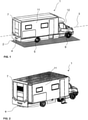
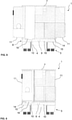
- the interior of the motorhome 1 can be enlarged considerably, as can be seen especially well in figures 5 and 7 .
- the second embodiment of a motorhome 1 according to the invention shown in Fig. 3 and Fig. 4 differs from the other two embodiments primarily in that there are no lateral room extension modules arranged in the superstructure 7.
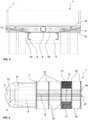
- a motorhome 1 always has an intermediate support structure 8 arranged between the vehicle frame 4 and the superstructure 7.
- the intermediate support structure 8 has a central beam 9 extending along the vehicle longitudinal axis 3 and several cantilevers 10 attached to it and extending transversely thereto.
- the central beam 9 is a tubular beam with high torsional stiffness.
- the beam 9 essentially runs from the rear end of the driver's cab 12 to the rear end of the superstructure 7.
- the cantilevers 10 run orthogonally to the central beam 9 and are aligned with cross beams 13 of the chassis 2 or of the vehicle frame 4, respectively, arranged below.
- the upper floor 14 is located on the cantilevers 10 and a lower floor 15 extends under the cantilevers 10. It is therefore a double floor structure which encloses the intermediate support structure 8 and thus provides good thermal insulation for the installations arranged in this area.
- the special feature of the intermediate support structure 8 according to the invention lies in a large gain in space, which is better usable and is located in the area of the intermediate support structure 8 and below.
- the crosswise hatching 19 in Fig. 3 shows this area, which is better usable compared to a conventional doubling of the vehicle frame 4.
- the same area 19 in Fig. 4 is not hatched crosswise but just lined, but the areas are identical. Only in the area of the wheel arches 17, as can be seen from the darker hatching used there, is this space broken through, as the rear wheels of chassis 2 project into it.
- tanks, storages, but also drives and guides for possible room extension modules 11, etc. can be arranged in the thus gained space 19 and the adjacent spaces. Also, this way a smooth floor 14 can be created for the superstructure 7 without having to displace the centre of gravity of the motorhome 1 upwards.
- a special highlight of the invention is the fact that a shower tray 18 can be arranged in room 19, which is better usable and created through the intermediate support structure 8 according to the invention.
- the shower tray can simply be recessed into the upper floor 14 of the superstructure 7.
- the room extension module 11 can be completely pushed over the shower tray 18 in the travel state as shown in Fig. 7 .
- the shower tray 18 disappears practically completely under the floor of the slideout 11 without restricting the usability of the kitchen area or toilet that may still be required when travelling.
- the shower tray 18 is well protected against the weather, dirt, frost and heat by the lower floor 15.
- the intermediate support structure 8 with the two floors 14 and 15 and the side walls not shown here but existing ensure that not only the shower tray 18 but also its drains and the tanks for fresh and waste water can be accommodated in this area and are also safely protected from the weather etc..
Description
- The present invention concerns a motorhome with a chassis which has at least one axle and which has, at least in some areas, a ladder-like vehicle frame extending along the vehicle longitudinal axis and on which a superstructure is arranged.
- Such motorhomes are generally known, see for example
DE 20 2005 007060 U1 . In the sense of this invention, a motorhome is to be understood primarily as a motorized vehicle such as a recreational vehicle. But the invention can also be implemented in non-motorized vehicles such as caravans. It also does not matter for which purposes the motorhome is used. It is only important that it has a superstructure which has an interior suitable for the permanent stay of people. It also makes no difference whether the motorhome is used for long journeys or very short journeys - for example within a city. - Usually motorized motorhomes are mounted on chassis ranging from conventional vans to those of trucks. These usually have, at least in some areas, a ladder-like vehicle frame. Such a vehicle frame usually has two long beams extending along the vehicle longitudinal axis, which are connected to each other by several short cross beams.
- In the construction of such motorhomes, a subframe, which is arranged on the actual chassis frame, is normally required nowadays to distribute the load of the superstructure and to achieve a level superstructure floor. This is practically a doubling of the ladder-like vehicle frame with the aim of creating a support possibility for the floor of the superstructure so that it also runs smoothly in the area of the rear axle if possible. Not only the wheel arches but also cross beams are mounted under the superstructure floor in the installation space of these common subframes. The longitudinal beams of such a subframe, like the vehicle frame, usually consist of U-profiles or rectangular tubes, which are mounted directly on and parallel to the profiles of the vehicle frame.
- The disadvantage of this conventional construction method is that the installation space in the area of the subframe is essentially lost for the use of technical installations. This is particularly disadvantageous for motorhomes, as they require a lot of installation space for tanks and other technical equipment in addition to the living space. So with limited exterior dimensions, at the end of the day installation space is used for the technical equipment, which one would prefer to use instead for the living space inside the superstructure, or the vehicle becomes larger and higher.
- The task of the invention is therefore to show a motorhome in which the installation space available in the vehicle is used more economically than in conventional construction methods to create a better usable interior in the superstructure.
- The solution to this problem is achieved with the motorhome according to
claim 1, that means a motorhome which is designed in the manner described above, in which additionally an intermediate support structure is arranged between the vehicle frame and the superstructure, the intermediate support structure comprising a central beam extending along the vehicle longitudinal axis and several cantilevers attached thereto and extending transversely thereto. This construction makes it possible to compensate for and significantly reduce the volume loss caused by the conventional, relatively wide subframe construction. The free space gained in this way allows for tanks and/or technical installations to be placed between the cantilevers in this area without the vehicle floor or superstructure having to be raised additionally. This also means that the centre of gravity of the vehicle lies lower compared to a solution with a doubled vehicle frame. Thus the motorhome according to invention has a better road holding. - Preferably, the superstructure has at least one room extension module displaceably attached to it. This room extension module, also referred to here as a slideout, functions according to a drawer-like functional principle and offers the possibility of extending the room of the motorhome by sliding out a room that is usually open towards the inside of the vehicle. Therefore, most such slideouts have three walls, a floor and a roof.
- Preferably, the central beam has a tubular cross-section at least in some areas. This design has the advantage that the central beam reaches approximately the same torsional stiffness as the ladder-like frame common so far. However, it is considerably lighter and less volume is used in areas where tanks and/or technical installations can be installed. For a standard, approximately 5-metre-long superstructure, the subframe has a base area of approximately 4 m2. For technical reasons, this leads to a subframe approximately 20 cm high according to the usual construction method. This means that approximately 0.8 m3 of volume are lost for possible technical equipment such as liquid tanks, technical installations and storage space. With the central tube proposed here, with a diameter of approximately 20 cm a volume of only about 0.1 m3 would be achieved in comparison, but with the same torsional stiffness as with the conventional subframe, as already mentioned, using a corresponding wall thickness. This makes it possible, for example, to arrange tanks with a total capacity of more than 500 litres in the space thus gained without having to raise the vehicle floor.
- Preferably, the central beam is arranged centrally on the vehicle frame. This leads to a symmetrical and central load distribution.
- It makes sense for the central beam to be at least as long as the area between a driver's cab and a rear end of the vehicle. This means that only the area of the motorhome chassis is provided with the intermediate support structure, in which the part of the superstructure is located that is primarily intended for living purposes or which is not intended for driving the vehicle.
- It is particularly useful if at least one cantilever, preferably all cantilevers, of the intermediate support structure is arranged above and aligned with an underlying beam of the vehicle frame. This allows an even greater overall height to be achieved between the cantilevers for the technical installations, tanks or storage spaces, etc. to be provided in this area.
- It is particularly advantageous if an upper, preferably smooth continuous, floor is arranged on the intermediate support structure. This results in a particularly usable floor surface in the area of the superstructure, because it is smooth. In addition, it is particularly desirable if a lower floor is arranged below the intermediate support structure. This protects the overlying components, technical installations, tanks or storage spaces, etc. from soiling from below.
- A double floor can be achieved by combining upper and lower floors. Herein, it is particularly advantageous if at least one tank is arranged between the lower floor and the upper floor. This way, the space required for load transfer is used to accommodate the tanks that are absolutely necessary in a motorhome and a high efficiency is achieved.
- The space between the lower floor and the upper floor is preferably laterally closed and thermally insulated. This way, the motorhome can also be used in winter, for example, without freezing any tanks, technical equipment or other installations located in the interspace between the lower and upper floor. This closed room also provides good overall shielding against the weather and other external influences. It makes sense to shift the interspace laterally in such a way, that also in the area between the wheel arches a lateral closing and insulation are present.
- Preferably, the intermediate support structure has a height which is at least so great that the intermediate support structure is flush with a wheel arch provided in the area of a rear axle. This makes it easier to arrange a smooth upper floor on the intermediate support structure. This has great advantages, especially when room extension modules are provided in the superstructure. In the best case scenario, these - especially if they are of a particularly large design - can even cover almost the entire length of the superstructure.
- Preferably, at least one drive and/or a guide for a room extension module mounted on the superstructure so as to be displaceable above the upper floor is arranged between the lower floor and the upper floor. This way, the space between the floors is also used to accommodate the drive or the guide for the room extension module. Thus, these components are not disturbingly arranged in the living space or in the room of the superstructure respectively and are also well protected against weather influences and the like.
- In a particularly preferred embodiment, at least one shower tray is recessed in the upper floor in such a way that a room extension module can be pushed over it. The upper side of the shower tray is therefore maximum flush with the upper side of the upper floor. This means that the interior of the motorhome can be reduced in a particularly efficient way by using large room extension modules. In addition, the reduction is mainly at the expense of the shower that means an equipment detail that is least urgently needed when driving.
- Accordingly, it is furthermore particularly desirable if the upper side of the upper floor is so smooth that a room extension module can be displaced on it.
- In the following, the invention will be explained in more detail using the examples shown in the drawings, wherein schematically show:
- Fig. 1
- a perspective view of a first motorhome according to the invention in the driving state;
- Fig. 2
- the motorhome shown in
Fig. 1 in a state in which a lateral room extension module has been displaced out of the superstructure; - Fig. 3
- an enlarged sectional view through the rear area of a second embodiment of a motorhome according to the invention with a viewing direction to the rear from the driver's cab to the rear axle;
- Fig. 4
- a plan view of a horizontal section transverse to the section shown in
Fig. 3 through the second embodiment of a motorhome according to the invention; - Fig. 5
- a section through the rear area of a third embodiment of a motorhome according to invention with a viewing direction from the driver's cab to the rear and the rear axle in an extended state of the room extension modules;
- Fig. 6
- the section shown in
Fig. 5 in the state with the room extension modules retracted (travel state); - Fig. 7
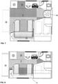
- a plan view of the layout of the superstructure of the motorhome shown in
Fig 5 when extended; and - Fig. 8
- the layout of the superstructure shown in
Fig. 6 in the state with the room extension modules retracted (travel state). - In the figures, identical reference numerals denote identical components in the three different embodiments partially differing from each other. However, all the embodiments of
motorhomes 1 according to the invention shown here always have achassis 2 which has, at least in some areas, a ladder-like vehicle frame 4 extending along the vehiclelongitudinal axis 3. Such avehicle frame 4 can be clearly seen inFig. 4 , while inFigs. 1 and 2 only the rearmost end of thevehicle frame 4 can be seen. In all examples shown here, thevehicle frame 4 connects therear axle 5 with thefront axle 6 and supports thesuperstructure 7 of therespective motorhome 1. - The first embodiment shown in
Figs. 1 and 2 and also the third embodiment shown inFigs. 5 to 8 both have two lateralroom extension modules 11 which each extend over the entire length and height of thesuperstructure 7 and which can be retracted or extended. Thus, the interior of themotorhome 1 can be enlarged considerably, as can be seen especially well infigures 5 and7 . - The second embodiment of a
motorhome 1 according to the invention shown inFig. 3 and Fig. 4 differs from the other two embodiments primarily in that there are no lateral room extension modules arranged in thesuperstructure 7. - As can be seen from the section views of
figures 3 ,5 and 6 , amotorhome 1 according to the invention always has anintermediate support structure 8 arranged between thevehicle frame 4 and thesuperstructure 7. Theintermediate support structure 8 has acentral beam 9 extending along the vehiclelongitudinal axis 3 andseveral cantilevers 10 attached to it and extending transversely thereto. In all the embodiments shown here, thecentral beam 9 is a tubular beam with high torsional stiffness. As can be seen inFig. 4 , thebeam 9 essentially runs from the rear end of the driver'scab 12 to the rear end of thesuperstructure 7. In the embodiments shown here, thecantilevers 10 run orthogonally to thecentral beam 9 and are aligned withcross beams 13 of thechassis 2 or of thevehicle frame 4, respectively, arranged below. Theupper floor 14 is located on thecantilevers 10 and alower floor 15 extends under thecantilevers 10. It is therefore a double floor structure which encloses theintermediate support structure 8 and thus provides good thermal insulation for the installations arranged in this area. - The special feature of the
intermediate support structure 8 according to the invention lies in a large gain in space, which is better usable and is located in the area of theintermediate support structure 8 and below. The crosswise hatching 19 inFig. 3 shows this area, which is better usable compared to a conventional doubling of thevehicle frame 4. Thesame area 19 inFig. 4 is not hatched crosswise but just lined, but the areas are identical. Only in the area of thewheel arches 17, as can be seen from the darker hatching used there, is this space broken through, as the rear wheels ofchassis 2 project into it. - In comparison to the conventional doubling of the
vehicle frame 4, this results in a considerably better usable space under theactual superstructure 7. Preferably tanks, storages, but also drives and guides for possibleroom extension modules 11, etc. can be arranged in the thus gainedspace 19 and the adjacent spaces. Also, this way asmooth floor 14 can be created for thesuperstructure 7 without having to displace the centre of gravity of themotorhome 1 upwards. - In addition, when using
lateral slideouts 11 insuperstructure 7, as can be clearly seen inFigs. 7 and 8 , this makes much better usable layouts or furnishings than previously possible. Thus, as shown at the top ofFig. 7 , the kitchen and toilet room can be arranged in a singlelateral slideout 11 and moved outwards in a single step. Accordingly, on the side ofsuperstructure 7 shown at the bottom ofFig. 7 , an outward foldable bench, for example, and also a foldable bedhead of a double bed can be moved or folded outwards in a very simple and elegant way, thus considerably improving and enlarging the usability of the living space. - A special highlight of the invention is the fact that a
shower tray 18 can be arranged inroom 19, which is better usable and created through theintermediate support structure 8 according to the invention. For this purpose, the shower tray can simply be recessed into theupper floor 14 of thesuperstructure 7. Thus theroom extension module 11 can be completely pushed over theshower tray 18 in the travel state as shown inFig. 7 . As can be seen in the comparison betweenFigs. 7 and 8 , theshower tray 18 disappears practically completely under the floor of the slideout 11 without restricting the usability of the kitchen area or toilet that may still be required when travelling. - The
shower tray 18 is well protected against the weather, dirt, frost and heat by thelower floor 15. Herein, theintermediate support structure 8 with the twofloors shower tray 18 but also its drains and the tanks for fresh and waste water can be accommodated in this area and are also safely protected from the weather etc.. -
- 1.
- motorhome
- 2.
- chassis
- 3.
- vehicle longitudinal axis
- 4.
- vehicle frame
- 5.
- rear axle
- 6.
- front axle
- 7.
- superstructure
- 8.
- intermediate support structure
- 9.
- central beam
- 10.
- cantilever
- 11.
- room extension module / slideout
- 12.
- driver's cab
- 13.
- cross beam of the vehicle frame
- 14.
- upper floor
- 15.
- lower floor
- 16.
- tank
- 17.
- wheel arch of the rear axle
- 18.
- shower tray
- 19.
- area of better usable space
Claims (15)
- Motorhome (1) with a chassis (2) which has at least one rear axle (5) and which has, at least in some areas, a ladder-like vehicle frame (4) extending along the vehicle longitudinal axis (3) and on which a superstructure (7) is arranged,
characterized in that
an intermediate support structure (8) is arranged between the vehicle frame (4) and the superstructure (7), the intermediate support structure (8) comprising a central beam (9) extending along the vehicle longitudinal axis (3) and several cantilevers (10) attached thereto and extending transversely thereto. - Motorhome according to claim 1,
wherein
the superstructure (7) has at least one room extension module (11) displaceably attached to it. - Motorhome according to any one of the preceding claims,
wherein
the central beam (9) is arranged centrally on the vehicle frame (4). - Motorhome according to any one of the preceding claims,
wherein
the central beam (9) has a tubular cross-section at least in some areas. - Motorhome according to any one of the preceding claims,
wherein
the central beam (9) is at least as long as an area between a driver's cab (12) and a rear end of the superstructure (7). - Motorhome according to any one of the preceding claims,
wherein
at least one cantilever (10), preferably all cantilevers (10), is arranged above and aligned with an underlying cross beam (13) of the vehicle frame (4). - Motorhome according to any one of the preceding claims,
wherein
at least one cantilever (10), preferably all cantilevers (10), have a crosssectional height which increases towards the central beam (9). - Motorhome according to any one of the preceding claims,
wherein
an upper, preferably smooth continuous, floor (14) is arranged on the intermediate support structure (8). - Motorhome according to any one of the preceding claims,
wherein
a lower floor (15) is arranged below the intermediate support structure (8). - Motorhome according to claims 8 and 9,
wherein
at least one tank is arranged between the lower floor (15) and the upper floor (14). - Motorhome according to claims 8 and 9, or according to claim 10
wherein
the space between the upper floor (14) and the lower floor (15) is laterally closed and thermally insulated. - Motorhome according to any one of the preceding claims,
wherein
the intermediate support structure (8) has a height which is at least so great that the intermediate support structure (8) is flush with a wheel arch (17) provided in the area of a rear axle (5). - Motorhome according to claims 8 and 9, or according to any one of claims 10 and 11,
wherein
at least one drive and/or a guide for a room extension module (11) mounted on the superstructure (7) so as to be displaceable above the upper floor (14) is arranged between the upper floor (14) and the lower floor (15). - Motorhome according to claim 8 or according to any one of claims 10 , 11, and 13,
wherein in the upper floor (14) at least one shower tray (18) is recessed so deeply that a room extension module (11) can be pushed over it. - Motorhome according to claim 8 or according to any one of claims 10 , 11, 13 and 14,
wherein
the upper side of the upper floor (14) is so smooth that a room extension module (11) can be displaced on it.
Applications Claiming Priority (2)
| Application Number | Priority Date | Filing Date | Title |
|---|---|---|---|
| DE102018210327.5A DE102018210327A1 (en) | 2018-06-25 | 2018-06-25 | Motorhome with a ladder-like vehicle frame |
| PCT/EP2019/066665 WO2020002232A1 (en) | 2018-06-25 | 2019-06-24 | Motorhome with a ladder-like vehicle frame |
Publications (2)
| Publication Number | Publication Date |
|---|---|
| EP3781437A1 EP3781437A1 (en) | 2021-02-24 |
| EP3781437B1 true EP3781437B1 (en) | 2022-02-16 |
Family
ID=67070832
Family Applications (1)
| Application Number | Title | Priority Date | Filing Date |
|---|---|---|---|
| EP19733732.2A Active EP3781437B1 (en) | 2018-06-25 | 2019-06-24 | Motorhome with a ladder-like vehicle frame |
Country Status (4)
| Country | Link |
|---|---|
| EP (1) | EP3781437B1 (en) |
| CN (1) | CN112313113B (en) |
| DE (1) | DE102018210327A1 (en) |
| WO (1) | WO2020002232A1 (en) |
Families Citing this family (2)
| Publication number | Priority date | Publication date | Assignee | Title |
|---|---|---|---|---|
| DE102018207895A1 (en) | 2018-05-18 | 2019-11-21 | Bayerische Motoren Werke Aktiengesellschaft | Motor vehicle with a pressure vessel system and operating method of a motor vehicle |
| RU2762443C1 (en) * | 2021-07-11 | 2021-12-21 | Общество с ограниченной ответственностью "РУФ-2" | Device of the supporting base of the vehicle |
Family Cites Families (9)
| Publication number | Priority date | Publication date | Assignee | Title |
|---|---|---|---|---|
| US5501504A (en) * | 1994-07-01 | 1996-03-26 | Fleetwood Enterprises Inc. | Motor home construction |
| DE10340018A1 (en) * | 2003-08-28 | 2005-03-24 | Goldschmitt Techmobil Gmbh | Mobile home with extended chassis |
| DE202005007060U1 (en) * | 2005-04-30 | 2006-06-08 | Aguti Produktenentwicklung & Design Gmbh | Rear extension especially for motor home is supported on two triangular sub frames fitted to the rear chassis |
| CA2533682C (en) * | 2006-01-23 | 2008-08-19 | Peel Truck & Trailer Equipment Ltd | Expandable trailer |
| EP2772418B1 (en) * | 2013-02-28 | 2016-11-23 | Scheuerle Fahrzeugfabrik GmbH | Means to widen a transport device, and transport device |
| CN204150113U (en) * | 2014-10-11 | 2015-02-11 | 云南力帆骏马车辆有限公司 | A kind of special-shaped longeron dump Truck Frame having subframe function concurrently |
| DE102015225269B4 (en) * | 2015-12-15 | 2021-11-25 | Protec Gmbh & Co. Kg | Motorhome |
| CN107650596A (en) * | 2017-09-20 | 2018-02-02 | 成都亿佰达电子科技有限公司 | A kind of caravan trailer chassis being bi-directionally connected |
| CN107719220A (en) * | 2017-11-14 | 2018-02-23 | 江苏旌航汽车有限公司 | A kind of caravan chassis skeleton and caravan |
-
2018
- 2018-06-25 DE DE102018210327.5A patent/DE102018210327A1/en not_active Withdrawn
-
2019
- 2019-06-24 CN CN201980042425.XA patent/CN112313113B/en active Active
- 2019-06-24 EP EP19733732.2A patent/EP3781437B1/en active Active
- 2019-06-24 WO PCT/EP2019/066665 patent/WO2020002232A1/en unknown
Also Published As
| Publication number | Publication date |
|---|---|
| CN112313113A (en) | 2021-02-02 |
| EP3781437A1 (en) | 2021-02-24 |
| WO2020002232A1 (en) | 2020-01-02 |
| DE102018210327A1 (en) | 2020-01-02 |
| CN112313113B (en) | 2023-04-28 |
Similar Documents
| Publication | Publication Date | Title |
|---|---|---|
| US4728144A (en) | Trailer construction | |
| US6619713B2 (en) | Slide-out room mechanism | |
| EP3781437B1 (en) | Motorhome with a ladder-like vehicle frame | |
| US7967356B2 (en) | Vehicular cargo space extender | |
| US9290213B2 (en) | Multi-level trailer | |
| US6860545B1 (en) | Travel trailer | |
| US10124845B1 (en) | Extensible trailer | |
| EP0599854A1 (en) | Mobile, multiuse, expandable rooms. | |
| US20110000730A1 (en) | Motorhome with onboard touring car, elevator, and crew cabin | |
| EP2212154A1 (en) | Cargo handling apparatus | |
| US9056575B2 (en) | Recreation vehicles with nesting expansion chambers | |
| GB2028729A (en) | Vehicle superstructure with a variable interior space | |
| KR101035476B1 (en) | Vehicle with loading boxes or loading surfaces | |
| DE102011106603C5 (en) | Motorhome with multipurpose raised floor | |
| US4929018A (en) | Truck ramp storage arrangement | |
| RU2445220C2 (en) | Rack car with support platforms moving between transporting position and position of motion between cars, and train consisting of said cars | |
| US4127299A (en) | Expanding camper arrangement | |
| US10479260B2 (en) | Recreational vehicles with slide-out floor sliding under main RV floor | |
| US9855880B1 (en) | Recreation vehicles with slide-out over the wheel wells | |
| US1350601A (en) | Bus construction | |
| JP5427020B2 (en) | Slope device with integrated tailgate | |
| ITRN20000025A1 (en) | SELF-SUPPORTING, REMOVABLE, VARIABLE VOLUME EQUIPPED CELL, FOR A MEANS OF TRANSPORT, PROVIDED WITH A LOAD COMPARTMENT, CLOSED | |
| US2228132A (en) | Delivery truck | |
| US3381994A (en) | Slide-a-room tent camper | |
| EP3790765B1 (en) | Motorhome with a room extension module |
Legal Events
| Date | Code | Title | Description |
|---|---|---|---|
| STAA | Information on the status of an ep patent application or granted ep patent |
Free format text: STATUS: UNKNOWN |
|
| STAA | Information on the status of an ep patent application or granted ep patent |
Free format text: STATUS: THE INTERNATIONAL PUBLICATION HAS BEEN MADE |
|
| PUAI | Public reference made under article 153(3) epc to a published international application that has entered the european phase |
Free format text: ORIGINAL CODE: 0009012 |
|
| STAA | Information on the status of an ep patent application or granted ep patent |
Free format text: STATUS: REQUEST FOR EXAMINATION WAS MADE |
|
| 17P | Request for examination filed |
Effective date: 20201116 |
|
| AK | Designated contracting states |
Kind code of ref document: A1 Designated state(s): AL AT BE BG CH CY CZ DE DK EE ES FI FR GB GR HR HU IE IS IT LI LT LU LV MC MK MT NL NO PL PT RO RS SE SI SK SM TR |
|
| AX | Request for extension of the european patent |
Extension state: BA ME |
|
| DAV | Request for validation of the european patent (deleted) | ||
| DAX | Request for extension of the european patent (deleted) | ||
| GRAP | Despatch of communication of intention to grant a patent |
Free format text: ORIGINAL CODE: EPIDOSNIGR1 |
|
| STAA | Information on the status of an ep patent application or granted ep patent |
Free format text: STATUS: GRANT OF PATENT IS INTENDED |
|
| INTG | Intention to grant announced |
Effective date: 20211118 |
|
| GRAS | Grant fee paid |
Free format text: ORIGINAL CODE: EPIDOSNIGR3 |
|
| GRAA | (expected) grant |
Free format text: ORIGINAL CODE: 0009210 |
|
| STAA | Information on the status of an ep patent application or granted ep patent |
Free format text: STATUS: THE PATENT HAS BEEN GRANTED |
|
| AK | Designated contracting states |
Kind code of ref document: B1 Designated state(s): AL AT BE BG CH CY CZ DE DK EE ES FI FR GB GR HR HU IE IS IT LI LT LU LV MC MK MT NL NO PL PT RO RS SE SI SK SM TR |
|
| REG | Reference to a national code |
Ref country code: GB Ref legal event code: FG4D |
|
| REG | Reference to a national code |
Ref country code: CH Ref legal event code: EP |
|
| REG | Reference to a national code |
Ref country code: DE Ref legal event code: R096 Ref document number: 602019011707 Country of ref document: DE |
|
| REG | Reference to a national code |
Ref country code: AT Ref legal event code: REF Ref document number: 1468690 Country of ref document: AT Kind code of ref document: T Effective date: 20220315 |
|
| REG | Reference to a national code |
Ref country code: IE Ref legal event code: FG4D |
|
| REG | Reference to a national code |
Ref country code: NL Ref legal event code: FP |
|
| REG | Reference to a national code |
Ref country code: LT Ref legal event code: MG9D |
|
| REG | Reference to a national code |
Ref country code: AT Ref legal event code: MK05 Ref document number: 1468690 Country of ref document: AT Kind code of ref document: T Effective date: 20220216 |
|
| PG25 | Lapsed in a contracting state [announced via postgrant information from national office to epo] |
Ref country code: SE Free format text: LAPSE BECAUSE OF FAILURE TO SUBMIT A TRANSLATION OF THE DESCRIPTION OR TO PAY THE FEE WITHIN THE PRESCRIBED TIME-LIMIT Effective date: 20220216 Ref country code: RS Free format text: LAPSE BECAUSE OF FAILURE TO SUBMIT A TRANSLATION OF THE DESCRIPTION OR TO PAY THE FEE WITHIN THE PRESCRIBED TIME-LIMIT Effective date: 20220216 Ref country code: PT Free format text: LAPSE BECAUSE OF FAILURE TO SUBMIT A TRANSLATION OF THE DESCRIPTION OR TO PAY THE FEE WITHIN THE PRESCRIBED TIME-LIMIT Effective date: 20220616 Ref country code: NO Free format text: LAPSE BECAUSE OF FAILURE TO SUBMIT A TRANSLATION OF THE DESCRIPTION OR TO PAY THE FEE WITHIN THE PRESCRIBED TIME-LIMIT Effective date: 20220516 Ref country code: LT Free format text: LAPSE BECAUSE OF FAILURE TO SUBMIT A TRANSLATION OF THE DESCRIPTION OR TO PAY THE FEE WITHIN THE PRESCRIBED TIME-LIMIT Effective date: 20220216 Ref country code: HR Free format text: LAPSE BECAUSE OF FAILURE TO SUBMIT A TRANSLATION OF THE DESCRIPTION OR TO PAY THE FEE WITHIN THE PRESCRIBED TIME-LIMIT Effective date: 20220216 Ref country code: ES Free format text: LAPSE BECAUSE OF FAILURE TO SUBMIT A TRANSLATION OF THE DESCRIPTION OR TO PAY THE FEE WITHIN THE PRESCRIBED TIME-LIMIT Effective date: 20220216 Ref country code: BG Free format text: LAPSE BECAUSE OF FAILURE TO SUBMIT A TRANSLATION OF THE DESCRIPTION OR TO PAY THE FEE WITHIN THE PRESCRIBED TIME-LIMIT Effective date: 20220516 |
|
| PG25 | Lapsed in a contracting state [announced via postgrant information from national office to epo] |
Ref country code: PL Free format text: LAPSE BECAUSE OF FAILURE TO SUBMIT A TRANSLATION OF THE DESCRIPTION OR TO PAY THE FEE WITHIN THE PRESCRIBED TIME-LIMIT Effective date: 20220216 Ref country code: LV Free format text: LAPSE BECAUSE OF FAILURE TO SUBMIT A TRANSLATION OF THE DESCRIPTION OR TO PAY THE FEE WITHIN THE PRESCRIBED TIME-LIMIT Effective date: 20220216 Ref country code: GR Free format text: LAPSE BECAUSE OF FAILURE TO SUBMIT A TRANSLATION OF THE DESCRIPTION OR TO PAY THE FEE WITHIN THE PRESCRIBED TIME-LIMIT Effective date: 20220517 Ref country code: FI Free format text: LAPSE BECAUSE OF FAILURE TO SUBMIT A TRANSLATION OF THE DESCRIPTION OR TO PAY THE FEE WITHIN THE PRESCRIBED TIME-LIMIT Effective date: 20220216 Ref country code: AT Free format text: LAPSE BECAUSE OF FAILURE TO SUBMIT A TRANSLATION OF THE DESCRIPTION OR TO PAY THE FEE WITHIN THE PRESCRIBED TIME-LIMIT Effective date: 20220216 |
|
| PGFP | Annual fee paid to national office [announced via postgrant information from national office to epo] |
Ref country code: CH Payment date: 20220629 Year of fee payment: 4 |
|
| PG25 | Lapsed in a contracting state [announced via postgrant information from national office to epo] |
Ref country code: IS Free format text: LAPSE BECAUSE OF FAILURE TO SUBMIT A TRANSLATION OF THE DESCRIPTION OR TO PAY THE FEE WITHIN THE PRESCRIBED TIME-LIMIT Effective date: 20220617 |
|
| PG25 | Lapsed in a contracting state [announced via postgrant information from national office to epo] |
Ref country code: SM Free format text: LAPSE BECAUSE OF FAILURE TO SUBMIT A TRANSLATION OF THE DESCRIPTION OR TO PAY THE FEE WITHIN THE PRESCRIBED TIME-LIMIT Effective date: 20220216 Ref country code: SK Free format text: LAPSE BECAUSE OF FAILURE TO SUBMIT A TRANSLATION OF THE DESCRIPTION OR TO PAY THE FEE WITHIN THE PRESCRIBED TIME-LIMIT Effective date: 20220216 Ref country code: RO Free format text: LAPSE BECAUSE OF FAILURE TO SUBMIT A TRANSLATION OF THE DESCRIPTION OR TO PAY THE FEE WITHIN THE PRESCRIBED TIME-LIMIT Effective date: 20220216 Ref country code: EE Free format text: LAPSE BECAUSE OF FAILURE TO SUBMIT A TRANSLATION OF THE DESCRIPTION OR TO PAY THE FEE WITHIN THE PRESCRIBED TIME-LIMIT Effective date: 20220216 Ref country code: DK Free format text: LAPSE BECAUSE OF FAILURE TO SUBMIT A TRANSLATION OF THE DESCRIPTION OR TO PAY THE FEE WITHIN THE PRESCRIBED TIME-LIMIT Effective date: 20220216 Ref country code: CZ Free format text: LAPSE BECAUSE OF FAILURE TO SUBMIT A TRANSLATION OF THE DESCRIPTION OR TO PAY THE FEE WITHIN THE PRESCRIBED TIME-LIMIT Effective date: 20220216 |
|
| REG | Reference to a national code |
Ref country code: DE Ref legal event code: R097 Ref document number: 602019011707 Country of ref document: DE |
|
| PG25 | Lapsed in a contracting state [announced via postgrant information from national office to epo] |
Ref country code: AL Free format text: LAPSE BECAUSE OF FAILURE TO SUBMIT A TRANSLATION OF THE DESCRIPTION OR TO PAY THE FEE WITHIN THE PRESCRIBED TIME-LIMIT Effective date: 20220216 |
|
| PLBE | No opposition filed within time limit |
Free format text: ORIGINAL CODE: 0009261 |
|
| STAA | Information on the status of an ep patent application or granted ep patent |
Free format text: STATUS: NO OPPOSITION FILED WITHIN TIME LIMIT |
|
| 26N | No opposition filed |
Effective date: 20221117 |
|
| PG25 | Lapsed in a contracting state [announced via postgrant information from national office to epo] |
Ref country code: MC Free format text: LAPSE BECAUSE OF FAILURE TO SUBMIT A TRANSLATION OF THE DESCRIPTION OR TO PAY THE FEE WITHIN THE PRESCRIBED TIME-LIMIT Effective date: 20220216 |
|
| REG | Reference to a national code |
Ref country code: BE Ref legal event code: MM Effective date: 20220630 |
|
| PG25 | Lapsed in a contracting state [announced via postgrant information from national office to epo] |
Ref country code: SI Free format text: LAPSE BECAUSE OF FAILURE TO SUBMIT A TRANSLATION OF THE DESCRIPTION OR TO PAY THE FEE WITHIN THE PRESCRIBED TIME-LIMIT Effective date: 20220216 |
|
| PG25 | Lapsed in a contracting state [announced via postgrant information from national office to epo] |
Ref country code: LU Free format text: LAPSE BECAUSE OF NON-PAYMENT OF DUE FEES Effective date: 20220624 Ref country code: IE Free format text: LAPSE BECAUSE OF NON-PAYMENT OF DUE FEES Effective date: 20220624 |
|
| PG25 | Lapsed in a contracting state [announced via postgrant information from national office to epo] |
Ref country code: BE Free format text: LAPSE BECAUSE OF NON-PAYMENT OF DUE FEES Effective date: 20220630 |
|
| PGFP | Annual fee paid to national office [announced via postgrant information from national office to epo] |
Ref country code: NL Payment date: 20230620 Year of fee payment: 5 Ref country code: FR Payment date: 20230622 Year of fee payment: 5 Ref country code: DE Payment date: 20230627 Year of fee payment: 5 |
|
| PGFP | Annual fee paid to national office [announced via postgrant information from national office to epo] |
Ref country code: IT Payment date: 20230630 Year of fee payment: 5 |
|
| REG | Reference to a national code |
Ref country code: CH Ref legal event code: PL |
|
| GBPC | Gb: european patent ceased through non-payment of renewal fee |
Effective date: 20230624 |