EP3781340B1 - External turning tool having a cutting portion with a transverse elongated damping mechanism - Google Patents
External turning tool having a cutting portion with a transverse elongated damping mechanism Download PDFInfo
- Publication number
- EP3781340B1 EP3781340B1 EP19713880.3A EP19713880A EP3781340B1 EP 3781340 B1 EP3781340 B1 EP 3781340B1 EP 19713880 A EP19713880 A EP 19713880A EP 3781340 B1 EP3781340 B1 EP 3781340B1
- Authority
- EP
- European Patent Office
- Prior art keywords
- damping
- cutting portion
- tool
- damping member
- turning tool
- Prior art date
- Legal status (The legal status is an assumption and is not a legal conclusion. Google has not performed a legal analysis and makes no representation as to the accuracy of the status listed.)
- Active
Links
Images


Classifications
-
- B—PERFORMING OPERATIONS; TRANSPORTING
- B23—MACHINE TOOLS; METAL-WORKING NOT OTHERWISE PROVIDED FOR
- B23B—TURNING; BORING
- B23B27/00—Tools for turning or boring machines; Tools of a similar kind in general; Accessories therefor
- B23B27/002—Tools for turning or boring machines; Tools of a similar kind in general; Accessories therefor with vibration damping means
-
- B—PERFORMING OPERATIONS; TRANSPORTING
- B23—MACHINE TOOLS; METAL-WORKING NOT OTHERWISE PROVIDED FOR
- B23B—TURNING; BORING
- B23B27/00—Tools for turning or boring machines; Tools of a similar kind in general; Accessories therefor
- B23B27/10—Cutting tools with special provision for cooling
-
- B—PERFORMING OPERATIONS; TRANSPORTING
- B23—MACHINE TOOLS; METAL-WORKING NOT OTHERWISE PROVIDED FOR
- B23B—TURNING; BORING
- B23B27/00—Tools for turning or boring machines; Tools of a similar kind in general; Accessories therefor
- B23B27/14—Cutting tools of which the bits or tips or cutting inserts are of special material
-
- B—PERFORMING OPERATIONS; TRANSPORTING
- B23—MACHINE TOOLS; METAL-WORKING NOT OTHERWISE PROVIDED FOR
- B23B—TURNING; BORING
- B23B29/00—Holders for non-rotary cutting tools; Boring bars or boring heads; Accessories for tool holders
- B23B29/04—Tool holders for a single cutting tool
- B23B29/12—Special arrangements on tool holders
-
- B—PERFORMING OPERATIONS; TRANSPORTING
- B23—MACHINE TOOLS; METAL-WORKING NOT OTHERWISE PROVIDED FOR
- B23B—TURNING; BORING
- B23B2210/00—Details of turning tools
-
- B—PERFORMING OPERATIONS; TRANSPORTING
- B23—MACHINE TOOLS; METAL-WORKING NOT OTHERWISE PROVIDED FOR
- B23B—TURNING; BORING
- B23B2250/00—Compensating adverse effects during turning, boring or drilling
- B23B2250/12—Cooling and lubrication
-
- B—PERFORMING OPERATIONS; TRANSPORTING
- B23—MACHINE TOOLS; METAL-WORKING NOT OTHERWISE PROVIDED FOR
- B23B—TURNING; BORING
- B23B2250/00—Compensating adverse effects during turning, boring or drilling
- B23B2250/16—Damping of vibrations
-
- B—PERFORMING OPERATIONS; TRANSPORTING
- B23—MACHINE TOOLS; METAL-WORKING NOT OTHERWISE PROVIDED FOR
- B23B—TURNING; BORING
- B23B29/00—Holders for non-rotary cutting tools; Boring bars or boring heads; Accessories for tool holders
- B23B29/02—Boring bars
- B23B29/022—Boring bars with vibration reducing means
Definitions
- the subject matter of the present application relates to external turning machining tools which include a vibration damping mechanism. More particularly, the subject matter of the present application pertains to turning tools having a non-blade-shaped cutting portion, instead of blade-shaped cutting portions of the sort commonly found in grooving and/or parting tools. Such tools, as per the preamble of attached independent claim 1, are known from document US 2007/089574 A1 .
- the damping effect, or vibration suppression, created by a damping mechanism in a turning tool is influenced mainly by three parameters: A) Damping member weight; B) Distance between a damping member center of mass and the clamping portion which is secured in a CNC machine; and C) Turning tool stiffness.
- these parameters are optimized/chosen per the machining application and/or turning tool geometry. In most scenarios, all three parameters are preferably maximized.
- Typical damped turning tools of the field have a relatively large length-to-width ratio, and have clamping and cutting portions and a tool body which extends therebetween. In a clamped position in the CNC machine, at least a portion of the clamping portion is rigidly clamped in the CNC machine, while the tool body and cutting portions are cantilevered therefrom.
- a typical damping mechanism includes a confined, elongated damping member which lies within a damping cavity, or damping recess, along the elongated tool body. The damping member interacts with the turning tool via a viscous and/or elastic material. To maximize the size/weight of the damping member, the required damping recess leaves the tool body with only a thin peripheral envelope.
- an effective non-damped turning tool must have an appropriately rigid structure and should be cost-efficient. Designing such a tool becomes even more complex, when a damping mechanism is to be implemented. Specifically - finding an appropriate location, orientation and/or enough space for a sufficiently heavy damping member while both preserving tool structure rigidity and proper tool clearance.
- the current invention provides a vibration damping solution for external turning tools which overcomes the aforementioned problems.
- the damping member angle can range between 45 and 135 degrees.
- the damping member angle can range between 80 and 100 degrees.
- the turning tool has a tool axis which extends centrally within the tool body parallel to the axial direction and the damping member has a center of mass which is offset from the tool axis.
- the damping member has a max member length measured between extremities of the damping member along the elongation axis; and the max member length is larger than a max member thickness measured between extremities in a direction perpendicular to the elongation axis.
- the max member length is at least 1.5 times larger than the max member thickness.
- the damping member is replaceable with damping members of different weights, each configured, or calibrated, for a specific, or range of damping scenarios.
- the damping recess has a recess elongation axis which forms a non-zero damping recess angle with the axial direction.
- the cutting portion includes a turning insert, and in a top view of the turning tool, the center of mass of the damping member and the turning insert are located on opposite sides of the tool axis.
- the damping mechanism can have an elastic member.
- the cutting portion has opposite cutting portion side surfaces, and the elongation axis can extend therebetween without intersecting the cutting portion side surfaces.
- the damping member can have unitary one-piece construction.
- the turning insert has a cutting edge formed at an intersection between an upward-facing rake surface and a forward-facing and/or side-facing relief surface.
- the elongation axis can extend parallel or substantially parallel to the relief surface.
- a turning tool 10 configured to suppress vibrations includes an elongated tool body 12 and a turning insert 14 secured in a pocket 15.
- the pocket 15 is configured to accommodate the turning insert 14.
- the turning insert 14 has at least one cutting edge 76 formed at a meeting between an upward-facing rake surface 78 and a forward-facing and/or side-facing relief surface 80.
- the turning tool 10 has, at opposite extremities of the tool body 12, a clamping portion 16 and a cutting portion 18.
- the cutting portion 18 further includes a damping mechanism 20.
- the elongated tool body 12 defines a longitudinal, or axial direction AD.
- the term longitudinal, or axial direction refers to any axis which is parallel to an elongation direction of the tool body 12.
- the axial direction AD can be determined by a projection direction of the tool body 12 which is cantilevered from a CNC machine.
- the turning tool 10 is secured, or coupled into the CNC machine via the clamping portion 16.
- the axial direction AD can also be perpendicular to a rotation axis of the machined workpiece.
- the tool body 12 also defines a centrally extending tool axis T which is parallel to the axial direction AD and passes centrally through the tool body 12. According to the present embodiment, the tool axis T and the axial direction AD both pass through the clamping and cutting portions 16, 18.
- the clamping portion 16 is configured to be clamped in a CNC machine, and can have a square cross section taken perpendicular to the tool axis T (axial cross section). When clamped in the CNC machine, the clamping portion 16 is considered as a rigid, static reference point with regard to references to vibration damping in the turning tool 10.
- the tool body 12 has a body peripheral surface 22 which extends along the axial direction AD between the clamping and cutting portions 16, 18. Specifically, the axial direction AD is parallel to the body peripheral surface 22. According to the present embodiment, the body peripheral surface 22 has opposite body top and bottom surfaces 28, 30and opposite body side surfaces 32 which extend between the body top and bottom surfaces 28, 30.
- the body peripheral surface 22 can have a square axial cross section taken perpendicular to the axial direction AD.
- the tool axis T and the axial direction AD are parallel to the body side surfaces 32.
- the tool axis T and the axial direction AD are also parallel to the body top and bottom surfaces 28, 30.
- the tool axis T can be located midway between the body side surfaces 32.
- the tool axis T can be located midway between the body top and bottom surfaces 28, 30.
- the turning tool 10 has a maximum tool width TW which is measured between outward extremities of the turning tool body 12 in a direction perpendicular to the body side surfaces 32 and in a direction perpendicular to the tool axis T.
- the turning tool 10 further has a maximum tool height TH which is measured between outward extremities of the tool body 12 in a direction parallel to the body side surfaces 32 and in a direction perpendicular to the tool axis T.
- the cutting portion 18 extends from the tool body 12.
- the cutting portion 18 has cutting portion top and bottom surfaces 29, 31 which extend from a tool front surface 33 towards the clamping portion 16.
- the cutting portion 18 further has cutting portion side surfaces 35 which extend between the cutting portion top and bottom surfaces 29, 31.
- the cutting portion 18 includes at least one pocket 15 and a turning insert 14 secured therein.
- the cutting portion 18 can further include a coolant conveying assembly 36 and coolant channels 38 which extend at least through the cutting portion 18.
- the cutting portion 18 has a different axial cross section shape than that of the tool body 12.
- the cutting portion 18 extends in the axial direction AD with the pocket 15 formed at the forwardmost axial end of the cutting portion 18.
- the damping mechanism 20 includes an elongated damping recess 40, an elongated damping member 42, at least one elastic member 44, a calibration mechanism 46 and a lid 48.
- the damping member 42 is entirely confined within the cutting portion 18. Stated differently, in the present example, no portion of the damping member 42 protrudes outwardly from the cutting portion 18. Thus, no portion of the damping member 42 is visible in any view of the cutting portion. Also, the damping member 42 does not extend in a rearward direction into the clamping portion 16.
- the damping member is made from a material with a relatively high density to achieve a high weight-to-volume ratio.
- the damping member 42 can be made of Tungsten. In the current example, the damping member 42 is made of a single piece of material and thus has unitary one-piece construction.
- the damping member 42 and especially a center of mass CM thereof, is located adjacent the tool front surface 33 at a location which is farthest possible from the clamping portion 16.
- the pocket 15 and the damping mechanism 20 at least partially overlap in the axial direction AD.
- a plane P perpendicular to the axial direction AD intersects both pocket 15 and the damping mechanism 20.
- orientation-related features relate to advantageous design which places the damping mechanism 20 at the cutting portion 18 to avoid compromising the structural integrity and/or stiffness of the tool body 12.
- the damping member 42 can have first and second end surfaces 50, 52 and a member peripheral surface 54 which extends therebetween. According to the present embodiment, the member peripheral surface 54 does not include a thread.
- the damping member 42 has a central elongation axis E which passes through the first and second end surfaces 50, 52.
- the elongation axis E extends in a damping member elongation direction.
- the elongation axis E forms a non-zero damping member angle ⁇ with the axial direction and with the tool axis T ( Fig. 4 ).
- the damping member angle ⁇ ranges preferably between 45 and 135 degrees. In the present example, the damping member angle ⁇ is 96 degrees.
- the elongation axis E is parallel, or substantially parallel to the tool front surface. According to the present embodiments, during machining, the elongation axis E extends parallel, or substantially parallel, to an operative relief surface 80 which extends from an operative cutting edge 76 that cuts the workpiece.
- the member peripheral surface 54 has a cylindrical shape, the central axis of which coincides with the elongation axis E.
- the center of mass CM is defined by a vertex.
- the center of mass CM lies on the elongation axis E.
- the damping member 42 is not centered with respect to the tool body 12.
- the center of mass CM does not lie in the tool axis T.
- a projection of the center of mass CM is offset from the tool axis T.
- the center of mass CM and the turning insert 14 are preferably located at opposite sides of the tool axis T.
- the center of mass CM is not located directly beneath, or under, the turning insert 14. In other words, in a plan view of the rake surface 78, the center of mass CM does not overlap a projection of the turning insert 14.
- the damping member 42 has a maximum member length ML measured between extremities of the damping member 42 along the elongation axis E.
- the damping member 42 also has a maximum member thickness MT measured between extremities thereof in a direction perpendicular to the elongation direction. It is understood that when the damping member 42 has a cylindrical body, the maximum member thickness MT corresponds to the diameter of the cylindrical body.
- the maximum member length ML is larger than the maximum member thickness MT.
- the maximum member length ML is preferably 1.2 times larger than the maximum member thickness MT.
- the elongated shape has a bigger rotational inertia than, e.g., a spherical or a cube shaped damping member.
- the elongated shape enables compactness, while avoiding various mechanisms of the turning tool 10 such as an insert clamping mechanism in the pocket 15, or coolant channels 38.
- the current position and orientation of the damping mechanism 20 is preferable in terms of maximum weight achieved in a relatively small confined volume, production efficiency and damping test results (as shown in Fig. 10 ).
- the damping member 42 can have two chamfers 56. Each chamfer 56 extends between the member peripheral surface 54 and each of the first and second end surfaces 50, 52. In a cross section along the elongation axis E, the chamfer 56 can appear straight. Each chamfer 56 is configured to abut the elastic member 44.
- the damping recess 40 is elongated and configured to accommodate the elongated damping member 42.
- the damping recess 40 is a blind hole, or recess, i.e., includes only a single opening 58.
- the damping recess 40 only opens out to, and the opening 58 is located in, the cutting portion bottom surface 31. This allows for a clean, protrusion-free, cutting portion top surface 29 which gives way for uninterrupted chip flow.
- this smooth upper surface is subjectively aesthetic, which is regarded as advantageous in terms of marketing value.
- the damping recess 40 has a recess elongation axis RE.
- the recess elongation axis RE forms a non-zero damping recess angle ⁇ with the axial direction AD.
- the damping recess angle ⁇ ranges preferably between 45 and 135 degrees. According to the present embodiments the damping recess angle ⁇ measures 96 degrees. It is understood that when the damping mechanism 20 is installed and the tool is non-operative, the damping member's elongation axis E and the recess elongation axis RE are aligned.
- the damping recess 40 can have a recess wall 60 which extends from a recess base surface 62 located at an inner-most portion of the damping recess 40 along the elongation axis RE.
- the recess wall 60 can be cylindrical.
- the recess wall 60 can open out to the body bottom surface 30.
- the recess wall 60 can have a recess female thread 64 configured to receive and correspond with an external male lid thread 66 of the lid 48.
- the lid 48 can also have an internal female lid thread 68 which is configured to receive and correspond with an adjustment screw 70, as will further explained below.
- the damping mechanism 20 has two elastic members 44.
- Each elastic member 44 can abut a respective chamfer 56.
- Each elastic member 44 can be an elastic O-ring made of rubber.
- the calibration mechanism 46 in an assembled position of the damping mechanism 20, can include, in the following order: a pressure plate 72, the adjustment screw 70, the lid 48 and a locating nut 74.
- the pressure plate 72 is located between a first end of the adjustment screw 70 and the elastic member 44, the adjustment screw 70 is threaded into the internal female lid thread 68, and the locating nut 74 is threaded at a second end of the adjustment screw 70.
- the adjustment screw 70 can be turned to calibrate the damping mechanism 20, i.e., to adjust the amount of force exerted onto the respective elastic member 44 via the pressure plate 72 which spreads the forces across the elastic member 44.
- the locating nut 74 is tightened to preserve the current calibration, or adjustment screw 70 location.
- the damping recess 40 opens out only to the body top surface 28.
- the rest of the features of the damping mechanism 20 are similar or identical to the first embodiment disclosed above.
Landscapes
- Engineering & Computer Science (AREA)
- Mechanical Engineering (AREA)
- Cutting Tools, Boring Holders, And Turrets (AREA)
- Milling Processes (AREA)
Description
- The subject matter of the present application relates to external turning machining tools which include a vibration damping mechanism. More particularly, the subject matter of the present application pertains to turning tools having a non-blade-shaped cutting portion, instead of blade-shaped cutting portions of the sort commonly found in grooving and/or parting tools. Such tools, as per the preamble of attached
independent claim 1, are known from documentUS 2007/089574 A1 . - In the current field it is known that the damping effect, or vibration suppression, created by a damping mechanism in a turning tool is influenced mainly by three parameters: A) Damping member weight; B) Distance between a damping member center of mass and the clamping portion which is secured in a CNC machine; and C) Turning tool stiffness. To maximize the damping effect, these parameters are optimized/chosen per the machining application and/or turning tool geometry. In most scenarios, all three parameters are preferably maximized.
- Typical damped turning tools of the field have a relatively large length-to-width ratio, and have clamping and cutting portions and a tool body which extends therebetween. In a clamped position in the CNC machine, at least a portion of the clamping portion is rigidly clamped in the CNC machine, while the tool body and cutting portions are cantilevered therefrom. A typical damping mechanism includes a confined, elongated damping member which lies within a damping cavity, or damping recess, along the elongated tool body. The damping member interacts with the turning tool via a viscous and/or elastic material. To maximize the size/weight of the damping member, the required damping recess leaves the tool body with only a thin peripheral envelope. This type of damping mechanism considerably reduces tool stiffness compared to tools with a solid/full tool body which does not include a damping mechanism therein. In summary, the above described damped turning tools maximize the damping member weight, at the expense of tool, or tool body, stiffness and the distance between the damping member center of mass and the clamping portion.
- Generally, an effective non-damped turning tool, among other features, must have an appropriately rigid structure and should be cost-efficient. Designing such a tool becomes even more complex, when a damping mechanism is to be implemented. Specifically - finding an appropriate location, orientation and/or enough space for a sufficiently heavy damping member while both preserving tool structure rigidity and proper tool clearance. The current invention provides a vibration damping solution for external turning tools which overcomes the aforementioned problems.
- The invention is defined by the features of
claim 1. Preferred embodiments are defined by the features of the dependent claims. - Any of the following features, either alone or in combination, may be applicable to any of the above aspects of the subject matter of the application:
- The damping member angle can range between 45 and 135 degrees.
- The damping member angle can range between 80 and 100 degrees.
- The turning tool has a tool axis which extends centrally within the tool body parallel to the axial direction and the damping member has a center of mass which is offset from the tool axis.
- The damping member has a max member length measured between extremities of the damping member along the elongation axis; and the max member length is larger than a max member thickness measured between extremities in a direction perpendicular to the elongation axis.
- The max member length is at least 1.5 times larger than the max member thickness.
- The damping member is replaceable with damping members of different weights, each configured, or calibrated, for a specific, or range of damping scenarios.
- The damping recess has a recess elongation axis which forms a non-zero damping recess angle with the axial direction.
- The cutting portion includes a turning insert, and in a top view of the turning tool, the center of mass of the damping member and the turning insert are located on opposite sides of the tool axis.
- The damping mechanism can have an elastic member.
- The damping mechanism can have a lid and a calibration mechanism which is configured to apply a permanent force onto the damping member against an elastic member.
- The damping member can be entirely confined within the cutting portion. Thus, no portion of the damping
member 42 is visible in any view of the cutting portion. Also, the damping member does not extend in a rearward direction into the clamping portion. - The damping member can have chamfers at opposite ends thereof.
- The cutting portion has opposite cutting portion side surfaces, and the elongation axis can extend therebetween without intersecting the cutting portion side surfaces.
- The damping member can have unitary one-piece construction.
- The damping member can be cylindrical.
- The turning insert has a cutting edge formed at an intersection between an upward-facing rake surface and a forward-facing and/or side-facing relief surface.
- The elongation axis can extend parallel or substantially parallel to the relief surface.
- The turning tool has coolant conveyance assembly with coolant channels which extend at least through the cutting portion.
- The cutting portion can have a different axial cross-sectional shape than that of the tool body.
- For a better understanding of the subject matter of the present application and to show how the same may be carried out in practice, reference will now be made to the accompanying drawings, in which:
-
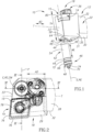
Fig. 1 is an exploded isometric view of a cutting portion of a turning tool with a transverse damping mechanism with a bottom opening; -
Fig. 2 is a top view of the turning tool ofFig. 1 showing hidden lines; -
Fig. 3 is a cross-sectional view taken along line III-III ofFig. 2 ; -
Fig. 4 is a cross-sectional view taken along line IV-IV ofFig. 2 ; -
Fig. 5 is a side view of the turning tool ofFig. 1 ; -
Fig. 6 is a cross-sectional view taken along the line VI-VI ofFig. 5 ; -
Fig. 7 is an exploded view of the damping mechanism ofFig. 1 ; -
Fig. 8 is a top view of a second embodiment of the turning tool with damping mechanism with a top opening; -
Fig. 9 is a cross-sectional view taken along line IX-IX ofFig. 8 ; and -
Fig. 10 is a Modal test result graph showing two Frequency Response Functions (FRF) representing, respectively, the same turning tool with and without a damping mechanism. - Where considered appropriate, reference numerals may be repeated among the figures to indicate corresponding or analogous elements.
- In the following description, various aspects of the subject matter of the present application will be described. For purposes of explanation, specific configurations and details are set forth in sufficient detail to provide a thorough understanding of the subject matter of the present application. However, it will also be apparent to one skilled in the art that the subject matter of the present application can be practiced without the specific configurations and details presented herein.
- Attention is drawn to
Fig. 1 . Aturning tool 10 configured to suppress vibrations includes anelongated tool body 12 and a turninginsert 14 secured in apocket 15. Thepocket 15 is configured to accommodate the turninginsert 14. The turninginsert 14 has at least onecutting edge 76 formed at a meeting between an upward-facingrake surface 78 and a forward-facing and/or side-facingrelief surface 80. Theturning tool 10 has, at opposite extremities of thetool body 12, a clampingportion 16 and a cuttingportion 18. The cuttingportion 18 further includes a dampingmechanism 20. Theelongated tool body 12 defines a longitudinal, or axial direction AD. The term longitudinal, or axial direction refers to any axis which is parallel to an elongation direction of thetool body 12. Specifically, the axial direction AD can be determined by a projection direction of thetool body 12 which is cantilevered from a CNC machine. Theturning tool 10 is secured, or coupled into the CNC machine via the clampingportion 16. The axial direction AD can also be perpendicular to a rotation axis of the machined workpiece. - The
tool body 12 also defines a centrally extending tool axis T which is parallel to the axial direction AD and passes centrally through thetool body 12. According to the present embodiment, the tool axis T and the axial direction AD both pass through the clamping and cuttingportions - The clamping
portion 16 is configured to be clamped in a CNC machine, and can have a square cross section taken perpendicular to the tool axis T (axial cross section). When clamped in the CNC machine, the clampingportion 16 is considered as a rigid, static reference point with regard to references to vibration damping in theturning tool 10. - Attention is drawn to
Figs. 2 ,6 and8 . Thetool body 12 has a bodyperipheral surface 22 which extends along the axial direction AD between the clamping and cuttingportions peripheral surface 22. According to the present embodiment, the bodyperipheral surface 22 has opposite body top andbottom surfaces 28, 30and opposite body side surfaces 32 which extend between the body top andbottom surfaces peripheral surface 22 can have a square axial cross section taken perpendicular to the axial direction AD. The tool axis T and the axial direction AD are parallel to the body side surfaces 32. The tool axis T and the axial direction AD are also parallel to the body top andbottom surfaces bottom surfaces - Attention is drawn to
Figs. 4 and6 . Theturning tool 10 has a maximum tool width TW which is measured between outward extremities of theturning tool body 12 in a direction perpendicular to the body side surfaces 32 and in a direction perpendicular to the tool axis T. Theturning tool 10 further has a maximum tool height TH which is measured between outward extremities of thetool body 12 in a direction parallel to the body side surfaces 32 and in a direction perpendicular to the tool axis T. - The
turning tool 10 has a height to width ratio HWR = TH/TW which is smaller than 3.5 and preferably smaller than 3. According to the present embodiment, the height to width ratio HWR is 1. This dimension ratio relates to available volume (internal or external) in theturning tool 10 where a dampingmechanism 20 can be implemented efficiently. Most, if not all blade-shaped tools have a height to width ratio of upwards of 4.5. Parting, or cut-off blade shaped tools are therefore too narrow to internally include a dampingmechanism 20 according to the present invention. Specifically, an elongated dampingmember 42 according to the present application which has an appropriate and effective weight cannot be implemented or be accommodated internally within a blade-shaped machining tool simply because it will not fit. - Attention is drawn to
Figs. 1-4 . The cuttingportion 18 extends from thetool body 12. The cuttingportion 18 has cutting portion top andbottom surfaces tool front surface 33 towards the clampingportion 16. The cuttingportion 18 further has cutting portion side surfaces 35 which extend between the cutting portion top andbottom surfaces portion 18 includes at least onepocket 15 and a turninginsert 14 secured therein. The cuttingportion 18 can further include acoolant conveying assembly 36 andcoolant channels 38 which extend at least through the cuttingportion 18. According to the present embodiment, the cuttingportion 18 has a different axial cross section shape than that of thetool body 12. According to the present embodiment, the cuttingportion 18 extends in the axial direction AD with thepocket 15 formed at the forwardmost axial end of the cuttingportion 18. - According to the present embodiments, the damping
mechanism 20 includes an elongated dampingrecess 40, an elongated dampingmember 42, at least oneelastic member 44, acalibration mechanism 46 and alid 48. - Attention is drawn to
Fig. 2 . According to the present embodiment, the dampingmember 42 is entirely confined within the cuttingportion 18. Stated differently, in the present example, no portion of the dampingmember 42 protrudes outwardly from the cuttingportion 18. Thus, no portion of the dampingmember 42 is visible in any view of the cutting portion. Also, the dampingmember 42 does not extend in a rearward direction into the clampingportion 16. The damping member is made from a material with a relatively high density to achieve a high weight-to-volume ratio. The dampingmember 42 can be made of Tungsten. In the current example, the dampingmember 42 is made of a single piece of material and thus has unitary one-piece construction. - The damping
member 42, and especially a center of mass CM thereof, is located adjacent thetool front surface 33 at a location which is farthest possible from the clampingportion 16. In the present embodiments, thepocket 15 and the dampingmechanism 20 at least partially overlap in the axial direction AD. In other words, a plane P perpendicular to the axial direction AD intersects bothpocket 15 and the dampingmechanism 20. - These orientation-related features relate to advantageous design which places the damping
mechanism 20 at the cuttingportion 18 to avoid compromising the structural integrity and/or stiffness of thetool body 12. - Attention is drawn to
Fig. 7 . The dampingmember 42 can have first and second end surfaces 50, 52 and a memberperipheral surface 54 which extends therebetween. According to the present embodiment, the memberperipheral surface 54 does not include a thread. The dampingmember 42 has a central elongation axis E which passes through the first and second end surfaces 50, 52. The elongation axis E extends in a damping member elongation direction. The elongation axis E forms a non-zero damping member angle α with the axial direction and with the tool axis T (Fig. 4 ). The damping member angle α ranges preferably between 45 and 135 degrees. In the present example, the damping member angle α is 96 degrees. The damping member angle α can be determined by tool geometry, i.e., in accordance with design efforts to maximize the available space/volume for the dampingmember 42 and consequently - its weight. The damping member angle α, can also be affected by other recesses in the cuttingportion 18 such as thepocket 15 and/orcoolant conveying assembly 36. Furthermore, in an axial view along the tool axis T, the orientation of the dampingmember 42, and consequently the elongation axis E is preferably upright, as seen inFig. 3 . In other words, in the present embodiments, the elongation axis E extends between the cutting portion side surfaces 35 without intersecting either. In the present embodiments, as seen inFig. 4 , the elongation axis E is parallel, or substantially parallel to the tool front surface. According to the present embodiments, during machining, the elongation axis E extends parallel, or substantially parallel, to anoperative relief surface 80 which extends from anoperative cutting edge 76 that cuts the workpiece. - According to the present example, the member
peripheral surface 54 has a cylindrical shape, the central axis of which coincides with the elongation axis E. The center of mass CM is defined by a vertex. According to the present embodiment, the center of mass CM lies on the elongation axis E. According to the present embodiments, the dampingmember 42 is not centered with respect to thetool body 12. In other words, in the present embodiment, the center of mass CM does not lie in the tool axis T. Specifically, in a top view of the cuttingportion 18, or a plan view of the cutting portion top surface 29 (as seen inFig. 2 ), a projection of the center of mass CM is offset from the tool axis T. This is advantageous, since the deviation, or lever arm, of the dampingmember 42 with respect to the tool axis T enables the dampingmember 42 to generate a suppression counter torque against torsional vibrations generated by machining forces. This is true in the present embodiments where thepocket 15 is also not centered with respect to the tool axis T. According to the present embodiment, in a top view of the cuttingportion 18, or a plan view of the cuttingportion top surface 29, as shown inFig. 2 , the center of mass CM and the turninginsert 14 are preferably located at opposite sides of the tool axis T. As seen inFig. 2 , the center of mass CM is not located directly beneath, or under, the turninginsert 14. In other words, in a plan view of therake surface 78, the center of mass CM does not overlap a projection of the turninginsert 14. - The damping
member 42 has a maximum member length ML measured between extremities of the dampingmember 42 along the elongation axis E. The dampingmember 42 also has a maximum member thickness MT measured between extremities thereof in a direction perpendicular to the elongation direction. It is understood that when the dampingmember 42 has a cylindrical body, the maximum member thickness MT corresponds to the diameter of the cylindrical body. The maximum member length ML is larger than the maximum member thickness MT. The maximum member length ML is preferably 1.2 times larger than the maximum member thickness MT. In other words, the dampingmember 42 has a length to thickness ratio ML/MT = LTR > 1.2. According to the present embodiment, the length to thickness ratio LTR is 1.5. This ratio relates directly to optimization of the shape of the dampingmember 42 to the available volume and to production restrictions in turning tools having a non-blade-shaped cutting portion. Specifically, the elongated shape has a bigger rotational inertia than, e.g., a spherical or a cube shaped damping member. In addition, the elongated shape enables compactness, while avoiding various mechanisms of theturning tool 10 such as an insert clamping mechanism in thepocket 15, orcoolant channels 38. In thecurrent turning tool 10, it was found that the current position and orientation of the dampingmechanism 20 is preferable in terms of maximum weight achieved in a relatively small confined volume, production efficiency and damping test results (as shown inFig. 10 ). As previously mentioned, increasing the dampingmember 42 weight and distance from the clampingportion 16 becomes more significant as the distance between the cuttingportion 18 and the clampingportion 16 increases, i.e., longer tools means larger projection from the CNC machine which leads to an increase in vibrations caused by machining. - The damping
member 42 can have twochamfers 56. Eachchamfer 56 extends between the memberperipheral surface 54 and each of the first and second end surfaces 50, 52. In a cross section along the elongation axis E, thechamfer 56 can appear straight. Eachchamfer 56 is configured to abut theelastic member 44. - The damping
recess 40 is elongated and configured to accommodate the elongated dampingmember 42. According to the present embodiment, the dampingrecess 40 is a blind hole, or recess, i.e., includes only asingle opening 58. According to the present embodiment, the dampingrecess 40 only opens out to, and theopening 58 is located in, the cuttingportion bottom surface 31. This allows for a clean, protrusion-free, cuttingportion top surface 29 which gives way for uninterrupted chip flow. Furthermore, this smooth upper surface is subjectively aesthetic, which is regarded as advantageous in terms of marketing value. - Attention is drawn to
Figs. 1-4 and9 . The dampingrecess 40 has a recess elongation axis RE. The recess elongation axis RE forms a non-zero damping recess angle β with the axial direction AD. The damping recess angle β ranges preferably between 45 and 135 degrees. According to the present embodiments the damping recess angle β measures 96 degrees. It is understood that when the dampingmechanism 20 is installed and the tool is non-operative, the damping member's elongation axis E and the recess elongation axis RE are aligned. - The damping
recess 40 can have arecess wall 60 which extends from arecess base surface 62 located at an inner-most portion of the dampingrecess 40 along the elongation axis RE. Therecess wall 60 can be cylindrical. Therecess wall 60 can open out to thebody bottom surface 30. At or adjacent theopening 58, therecess wall 60 can have a recessfemale thread 64 configured to receive and correspond with an externalmale lid thread 66 of thelid 48. Thelid 48 can also have an internalfemale lid thread 68 which is configured to receive and correspond with anadjustment screw 70, as will further explained below. - According to the present embodiment, the damping
mechanism 20 has twoelastic members 44. Eachelastic member 44 can abut arespective chamfer 56. Eachelastic member 44 can be an elastic O-ring made of rubber. - According to the present embodiment, in an assembled position of the damping
mechanism 20, thecalibration mechanism 46 can include, in the following order: apressure plate 72, theadjustment screw 70, thelid 48 and a locatingnut 74. Thepressure plate 72 is located between a first end of theadjustment screw 70 and theelastic member 44, theadjustment screw 70 is threaded into the internalfemale lid thread 68, and the locatingnut 74 is threaded at a second end of theadjustment screw 70. Once thelid 48 has been firmly tightened into the recessfemale thread 64, theadjustment screw 70 can be turned to calibrate the dampingmechanism 20, i.e., to adjust the amount of force exerted onto the respectiveelastic member 44 via thepressure plate 72 which spreads the forces across theelastic member 44. Once the dampingmechanism 20 has been properly calibrated, i.e., the desired force has been achieved, the locatingnut 74 is tightened to preserve the current calibration, oradjustment screw 70 location. - Attention is drawn to
Figs. 8 and 9 . According to a second embodiment, the dampingrecess 40 opens out only to thebody top surface 28. The rest of the features of the dampingmechanism 20 are similar or identical to the first embodiment disclosed above.
Claims (14)
- A non-blade shaped external turning tool (10) comprising:an elongated tool body (12) having opposite clamping and cutting portions (16, 18) defining an axial direction (AD) therebetween;a damping mechanism (20) at the cutting portion (18), the damping mechanism (20) comprising an elongated damping member (42) having an elongation axis (E); anda turning insert (14) removably retained in a pocket (15) of the cutting portion (16); wherein:characterized in that:the elongation axis (E) forms a non-zero damping member angle (α) with the axial direction (AD);the cutting portion (18) has opposite cutting portion top and bottom surfaces (29, 31) and an elongated damping recess (40) configured to accommodate the damping member (42); and:the damping recess (40) opens out to exactly one of the cutting portion top and bottom surfaces (29, 31);
a plane (P) perpendicular to the axial direction (AD) intersects both the turning insert (14) and the damping mechanism (20). - The external turning tool (10) according to claim 1, wherein the damping member angle (α) ranges from 45 to 135 degrees, preferably from 80 to 100 degrees.
- The external turning tool (10) according to claim 1 or 2, wherein:the external turning tool (10) has a tool axis (T) which extends centrally within the tool body (12), parallel to the axial direction (AD); andthe damping member (42) has a center of mass (CM) which is offset from the tool axis (T).
- The external turning tool (10) according to any one of claims 1 to 3, wherein:the damping member (42) has a maximum member length (ML) measured between extremities of the damping member (42) along the elongation axis (E); andthe maximum member length (ML) is larger than a maximum member thickness (MT) measured between extremities in a direction perpendicular to the elongation axis (E); andpreferably the maximum member length (ML) is at least 1.5 times larger than the maximum member thickness (MT).
- The external turning tool (10) according to any one of claims 1 to 4, wherein the damping mechanism (20) comprises an elastic member (44).
- The external turning tool (10) according to any one of claims 1 to 5, wherein the damping mechanism (20) further comprises a lid (48) and a calibration mechanism (46) which is configured to apply a permanent force onto the damping member (42) against an elastic member (44).
- The external turning tool (10) according to any one of claims 1 to 6, wherein the damping member (42) is entirely confined within the cutting portion (18), such that no portion of the damping member (42) is visible in any view of the cutting portion.
- The external turning tool (10) according to any one of claims 1 to 7, wherein the cutting portion (18) has opposite cutting portion side surfaces (35); and wherein the elongation axis (E) does not intersect the cutting portion side surfaces (35).
- The external turning tool (10) according to any one of claims 1 to 8, further comprising a coolant conveyance assembly (36) including a coolant channel (38) which extends at least through the cutting portion (18).
- The external turning tool (10) according to any one of claims 1 to 9, wherein the damping mechanism (42) does not extend in a rearward direction into the clamping portion (16).
- The external turning tool (10) according to any one of claims 1 to 10, wherein:the turning insert (14) comprises a cutting edge (76) formed at an intersection between a rake surface (78) and a relief surface (80); andthe elongation axis (E) extends parallel or substantially parallel to the relief surface (78).
- The external turning tool (10) according to any one of claims 1 to 11, wherein:
in a top view of the external turning tool (10), a center of mass (CM) of the damping member (42) is not located directly under the turning insert (14). - The external turning tool (10) according to any one of claims 1 to 12, wherein:the damping member (42) is entirely confined within the cutting portion (16) such that no portion of the damping member (42) is visible in any view of the cutting portion (16); andthe damping member angle (α) which ranges from 45 to 135 degrees; andpreferably the cutting portion (18) has a different axial cross-sectional shape than that of the clamping portion (16) and/or preferably the damping mechanism (42) does not extend in a rearward direction into the clamping portion (16).
- The external turning tool (10) according to any one of claims 1 to 13, wherein:the damping member (42) is entirely confined within the cutting portion (16) such that no portion of the damping member (42) is visible in any view of the cutting portion (16); andthe damping member (42) interacts with the tool body (12) via a viscous material; andpreferably the cutting portion (18) has a different axial cross-sectional shape than that of the clamping portion (16) and/or preferably the damping mechanism (42) does not extend in a rearward direction into the clamping portion (16).
Applications Claiming Priority (2)
| Application Number | Priority Date | Filing Date | Title |
|---|---|---|---|
| US15/953,726 US10953471B2 (en) | 2018-04-16 | 2018-04-16 | External turning tool having a cutting portion with a transverse elongated damping mechanism |
| PCT/IL2019/050262 WO2019202581A1 (en) | 2018-04-16 | 2019-03-10 | External turning tool having a cutting portion with a transverse elongated damping mechanism |
Publications (2)
| Publication Number | Publication Date |
|---|---|
| EP3781340A1 EP3781340A1 (en) | 2021-02-24 |
| EP3781340B1 true EP3781340B1 (en) | 2025-01-22 |
Family
ID=65951847
Family Applications (1)
| Application Number | Title | Priority Date | Filing Date |
|---|---|---|---|
| EP19713880.3A Active EP3781340B1 (en) | 2018-04-16 | 2019-03-10 | External turning tool having a cutting portion with a transverse elongated damping mechanism |
Country Status (10)
| Country | Link |
|---|---|
| US (1) | US10953471B2 (en) |
| EP (1) | EP3781340B1 (en) |
| JP (1) | JP7323540B2 (en) |
| KR (1) | KR102643844B1 (en) |
| CN (1) | CN111989180B (en) |
| CA (1) | CA3097080A1 (en) |
| IL (1) | IL277249B2 (en) |
| PL (1) | PL3781340T3 (en) |
| TW (1) | TWI772614B (en) |
| WO (1) | WO2019202581A1 (en) |
Families Citing this family (4)
| Publication number | Priority date | Publication date | Assignee | Title |
|---|---|---|---|---|
| CN112238227B (en) * | 2019-07-17 | 2024-07-30 | 肯纳金属公司 | Cutting tool holder with improved damping effect |
| TWI718023B (en) * | 2020-03-06 | 2021-02-01 | 世邦興業股份有限公司 | Shock absorption damping structure of tool holder |
| WO2022084988A2 (en) * | 2020-10-20 | 2022-04-28 | Iscar Ltd. | Coolant conduit for a parting-off tool assembly |
| JP2023079615A (en) * | 2021-11-29 | 2023-06-08 | 株式会社Moldino | anti-vibration tool holder |
Citations (1)
| Publication number | Priority date | Publication date | Assignee | Title |
|---|---|---|---|---|
| US20070089574A1 (en) * | 2003-11-26 | 2007-04-26 | Daisuke Murakami | Vibration suppressing cutting tool |
Family Cites Families (51)
| Publication number | Priority date | Publication date | Assignee | Title |
|---|---|---|---|---|
| US545416A (en) * | 1895-08-27 | shaver | ||
| US1134300A (en) * | 1914-06-13 | 1915-04-06 | Charles H Vinal | Concrete-mixer. |
| US1816538A (en) * | 1927-01-26 | 1931-07-28 | Kern Bernard | Carpet and floor cleaner |
| US3576060A (en) * | 1968-03-28 | 1971-04-27 | Warner Swasey Co | Insert bit having vibration-dampening properties |
| US3642378A (en) * | 1969-11-03 | 1972-02-15 | Heald Machine Co | Boring bar |
| CH528322A (en) | 1970-09-04 | 1972-09-30 | Mach Andre Bechler S A Fab De | Automatic turning machine |
| US3774730A (en) | 1972-04-19 | 1973-11-27 | Nl Industries Inc | Tool holder |
| US3923414A (en) * | 1973-07-16 | 1975-12-02 | Valeron Corp | Vibration damping support |
| SU545416A1 (en) * | 1975-04-01 | 1977-02-05 | Ленинградский Дважды Ордена Ленина И Ордена Октябрьской Революции Металлический Завод Им.22Съезда Кпсс | Cutter |
| SU1134300A1 (en) * | 1982-04-01 | 1985-01-15 | Предприятие П/Я В-8711 | Boring arbor |
| US4616738A (en) * | 1983-07-27 | 1986-10-14 | Shurtliff Norval E | Damped boring bar and tool holder |
| US5332339A (en) * | 1991-06-19 | 1994-07-26 | Mitsubishi Materials Corporation | Throw-away cutting tool |
| RU1816538C (en) * | 1991-06-27 | 1993-05-23 | Университет дружбы народов им.Патриса Лумумбы | Cut-off cutter |
| RU2011478C1 (en) * | 1991-11-29 | 1994-04-30 | Российский Университет Дружбы Народов | Cutting tool |
| JPH073903U (en) | 1993-06-21 | 1995-01-20 | 三菱自動車工業株式会社 | Cutting tool |
| JPH09300111A (en) * | 1996-05-16 | 1997-11-25 | Toshiba Tungaloy Co Ltd | Bite |
| SE511717C2 (en) | 1997-05-22 | 1999-11-15 | Sandvik Ab | Holder for turning operations |
| JP3692256B2 (en) * | 1999-04-07 | 2005-09-07 | 住友電気工業株式会社 | Replaceable cutting edge rotary cutting tool |
| US6443673B1 (en) | 2000-01-20 | 2002-09-03 | Kennametal Inc. | Tunable boring bar for suppressing vibrations and method thereof |
| JP4552214B2 (en) * | 2000-09-05 | 2010-09-29 | エヌティーエンジニアリング株式会社 | Chatter prevention structure for work machines |
| JP2002154003A (en) * | 2000-11-15 | 2002-05-28 | Mitsubishi Materials Corp | Cutting tools |
| SE522081C2 (en) * | 2000-12-06 | 2004-01-13 | Sandvik Ab | Tools for machining in metallic materials |
| JP2003062703A (en) | 2001-08-21 | 2003-03-05 | Mitsubishi Materials Corp | Damping tool |
| JP2003062704A (en) * | 2001-08-27 | 2003-03-05 | Mitsubishi Materials Corp | Damping tool |
| US6619165B2 (en) | 2002-02-01 | 2003-09-16 | Kennametal Inc. | Tunable toolholder |
| JP2003334702A (en) * | 2002-05-16 | 2003-11-25 | Sumitomo Electric Ind Ltd | Cutting tools |
| EP1535682A1 (en) * | 2003-11-26 | 2005-06-01 | Sumitomo Electric Hardmetal Corp. | Vibration-suppressing cutting tool |
| JP4085101B2 (en) * | 2004-04-20 | 2008-05-14 | 住友電工ハードメタル株式会社 | Cutting tools and machine tools |
| JP2005305600A (en) * | 2004-04-22 | 2005-11-04 | Mitsubishi Materials Corp | Boring bar and processing method thereof |
| US7987954B2 (en) * | 2004-06-18 | 2011-08-02 | Mcpherson Matthew A | Harmonic damper |
| US7234379B2 (en) | 2005-06-28 | 2007-06-26 | Ingvar Claesson | Device and a method for preventing or reducing vibrations in a cutting tool |
| US7128501B1 (en) * | 2005-07-05 | 2006-10-31 | Sandor Sipos | Lathe tool assembly |
| DE102006026967A1 (en) | 2006-06-09 | 2007-12-13 | Rolls-Royce Deutschland Ltd & Co Kg | Method for producing a cutting tool |
| SE530579C2 (en) * | 2006-11-28 | 2008-07-08 | Sandvik Intellectual Property | Tools and basic body for multi-channel chip separation machining |
| CN201483009U (en) * | 2009-07-29 | 2010-05-26 | 罗堃锜 | Transmission locking structure for fine-tuning boring head |
| JP5433346B2 (en) | 2009-08-21 | 2014-03-05 | 新日本工機株式会社 | Turning tool stay and turbine rotor machining lathe |
| JP5451373B2 (en) | 2009-10-30 | 2014-03-26 | ユキワ精工株式会社 | Tool holder |
| SE535054C2 (en) * | 2010-03-17 | 2012-03-27 | Sandvik Intellectual Property | Milling tools for cutting machining with damping means arranged in the tool body |
| KR101258519B1 (en) | 2010-12-20 | 2013-04-29 | 두산중공업 주식회사 | Apparatus for damping vibration of tool carriage in lathe |
| DE102010063725B4 (en) | 2010-12-21 | 2015-10-08 | Siemens Aktiengesellschaft | Component with a filled cavity, use of this component and method for its preparation |
| US8784016B2 (en) | 2011-07-01 | 2014-07-22 | Kennametal Inc. | Rotary cutting tool with vibration damping device |
| DE102013101854A1 (en) | 2013-02-05 | 2014-08-07 | Franz Haimer Maschinenbau Kg | Chuck with vibration reduction |
| US9168594B2 (en) * | 2013-08-23 | 2015-10-27 | Kennametal Inc | Toolholder with externally mounted tunable absorber mass |
| FR3014517B1 (en) | 2013-12-05 | 2016-01-01 | Seco E P B | DAMPING ELEMENT ADAPTABLE TO AT LEAST ONE EXTRINSIC FACTOR OF THE SHOCK ABSORBER |
| EP2946857B1 (en) | 2014-05-19 | 2019-10-16 | Sandvik Intellectual Property AB | Turning tool holder and cutting tool insert |
| US9579730B2 (en) | 2014-06-30 | 2017-02-28 | Kennametal Inc. | Vibration absorber with high viscous dampening |
| US9616502B2 (en) | 2014-08-12 | 2017-04-11 | Iscar, Ltd. | Cutting tool holder with vibration damping weight assembly |
| US9574634B2 (en) * | 2015-05-29 | 2017-02-21 | Monkula Enterprise Co., Ltd. | Damper for a cutting tool |
| US9993876B2 (en) | 2015-12-21 | 2018-06-12 | Iscar, Ltd. | Cutting tool holder with vibration damping weight assembly |
| EP3222376B1 (en) * | 2016-03-24 | 2019-01-23 | Seco Tools AB | Grooving blade, grooving tool and method of grooving a metallic workpiece |
| KR102566326B1 (en) | 2016-08-31 | 2023-08-14 | 마큐 에이비 | Rotatable assemblies, machined bar assemblies and methods therefor |
-
2018
- 2018-04-16 US US15/953,726 patent/US10953471B2/en active Active
-
2019
- 2019-02-22 TW TW108105951A patent/TWI772614B/en not_active IP Right Cessation
- 2019-03-10 CA CA3097080A patent/CA3097080A1/en active Pending
- 2019-03-10 JP JP2020545471A patent/JP7323540B2/en active Active
- 2019-03-10 IL IL277249A patent/IL277249B2/en unknown
- 2019-03-10 WO PCT/IL2019/050262 patent/WO2019202581A1/en not_active Ceased
- 2019-03-10 PL PL19713880.3T patent/PL3781340T3/en unknown
- 2019-03-10 EP EP19713880.3A patent/EP3781340B1/en active Active
- 2019-03-10 CN CN201980025961.9A patent/CN111989180B/en active Active
- 2019-03-10 KR KR1020207032898A patent/KR102643844B1/en active Active
Patent Citations (1)
| Publication number | Priority date | Publication date | Assignee | Title |
|---|---|---|---|---|
| US20070089574A1 (en) * | 2003-11-26 | 2007-04-26 | Daisuke Murakami | Vibration suppressing cutting tool |
Also Published As
| Publication number | Publication date |
|---|---|
| CA3097080A1 (en) | 2019-10-24 |
| BR112020021043A2 (en) | 2021-01-19 |
| TW201943476A (en) | 2019-11-16 |
| IL277249B2 (en) | 2024-02-01 |
| TWI772614B (en) | 2022-08-01 |
| WO2019202581A1 (en) | 2019-10-24 |
| JP2021518815A (en) | 2021-08-05 |
| US20190314902A1 (en) | 2019-10-17 |
| CN111989180B (en) | 2024-03-26 |
| KR20200141088A (en) | 2020-12-17 |
| CN111989180A (en) | 2020-11-24 |
| KR102643844B1 (en) | 2024-03-07 |
| PL3781340T3 (en) | 2025-04-14 |
| IL277249B1 (en) | 2023-10-01 |
| US10953471B2 (en) | 2021-03-23 |
| EP3781340A1 (en) | 2021-02-24 |
| IL277249A (en) | 2020-10-29 |
| JP7323540B2 (en) | 2023-08-08 |
Similar Documents
| Publication | Publication Date | Title |
|---|---|---|
| CA3008582C (en) | Cutting tool holder with vibration damping weight assembly | |
| US10953471B2 (en) | External turning tool having a cutting portion with a transverse elongated damping mechanism | |
| KR102358913B1 (en) | Hole processing tool and guide pad adjustment mechanism therefor | |
| EP3763468B1 (en) | Milling cutter | |
| EP3144086B1 (en) | A tool body and a turning tool for grooving operations | |
| JP2004514567A (en) | Cutting tools | |
| JP7518078B2 (en) | Rotary cutting body having an insert pocket with a seat surface provided with a plurality of abutment elements, rotary cutting tool and insert | |
| CN110087807A (en) | Cutting tip and indexable insert blade type rotary cutting tool | |
| JP2021518815A5 (en) | ||
| TW201834771A (en) | Tool holder and cutting tool with position adjustment element configuration | |
| WO2020203463A1 (en) | Cutting insert and rotary cutting tool | |
| JP7043933B2 (en) | Cutting edge position adjustment mechanism and milling tool | |
| RU2778772C2 (en) | Turning tool for external turning, having cutting part with transverse elongated damping mechanism | |
| BR112020021043B1 (en) | EXTERNAL TURNING TOOL IN DIFFERENT BLADE SHAPE | |
| JP7243001B2 (en) | milling tool | |
| JP7069296B2 (en) | Front milling | |
| JP7020245B2 (en) | Cutting edge position adjustment mechanism and milling tool |
Legal Events
| Date | Code | Title | Description |
|---|---|---|---|
| STAA | Information on the status of an ep patent application or granted ep patent |
Free format text: STATUS: UNKNOWN |
|
| STAA | Information on the status of an ep patent application or granted ep patent |
Free format text: STATUS: THE INTERNATIONAL PUBLICATION HAS BEEN MADE |
|
| PUAI | Public reference made under article 153(3) epc to a published international application that has entered the european phase |
Free format text: ORIGINAL CODE: 0009012 |
|
| STAA | Information on the status of an ep patent application or granted ep patent |
Free format text: STATUS: REQUEST FOR EXAMINATION WAS MADE |
|
| 17P | Request for examination filed |
Effective date: 20201116 |
|
| AK | Designated contracting states |
Kind code of ref document: A1 Designated state(s): AL AT BE BG CH CY CZ DE DK EE ES FI FR GB GR HR HU IE IS IT LI LT LU LV MC MK MT NL NO PL PT RO RS SE SI SK SM TR |
|
| AX | Request for extension of the european patent |
Extension state: BA ME |
|
| DAV | Request for validation of the european patent (deleted) | ||
| DAX | Request for extension of the european patent (deleted) | ||
| STAA | Information on the status of an ep patent application or granted ep patent |
Free format text: STATUS: EXAMINATION IS IN PROGRESS |
|
| 17Q | First examination report despatched |
Effective date: 20240506 |
|
| GRAP | Despatch of communication of intention to grant a patent |
Free format text: ORIGINAL CODE: EPIDOSNIGR1 |
|
| STAA | Information on the status of an ep patent application or granted ep patent |
Free format text: STATUS: GRANT OF PATENT IS INTENDED |
|
| INTG | Intention to grant announced |
Effective date: 20240828 |
|
| GRAS | Grant fee paid |
Free format text: ORIGINAL CODE: EPIDOSNIGR3 |
|
| GRAA | (expected) grant |
Free format text: ORIGINAL CODE: 0009210 |
|
| STAA | Information on the status of an ep patent application or granted ep patent |
Free format text: STATUS: THE PATENT HAS BEEN GRANTED |
|
| AK | Designated contracting states |
Kind code of ref document: B1 Designated state(s): AL AT BE BG CH CY CZ DE DK EE ES FI FR GB GR HR HU IE IS IT LI LT LU LV MC MK MT NL NO PL PT RO RS SE SI SK SM TR |
|
| P01 | Opt-out of the competence of the unified patent court (upc) registered |
Free format text: CASE NUMBER: APP_65887/2024 Effective date: 20241213 |
|
| REG | Reference to a national code |
Ref country code: GB Ref legal event code: FG4D |
|
| REG | Reference to a national code |
Ref country code: CH Ref legal event code: EP |
|
| REG | Reference to a national code |
Ref country code: IE Ref legal event code: FG4D |
|
| REG | Reference to a national code |
Ref country code: DE Ref legal event code: R096 Ref document number: 602019065060 Country of ref document: DE |
|
| REG | Reference to a national code |
Ref country code: SE Ref legal event code: TRGR |
|
| REG | Reference to a national code |
Ref country code: NL Ref legal event code: MP Effective date: 20250122 |
|
| PG25 | Lapsed in a contracting state [announced via postgrant information from national office to epo] |
Ref country code: NL Free format text: LAPSE BECAUSE OF FAILURE TO SUBMIT A TRANSLATION OF THE DESCRIPTION OR TO PAY THE FEE WITHIN THE PRESCRIBED TIME-LIMIT Effective date: 20250122 |
|
| PG25 | Lapsed in a contracting state [announced via postgrant information from national office to epo] |
Ref country code: RS Free format text: LAPSE BECAUSE OF FAILURE TO SUBMIT A TRANSLATION OF THE DESCRIPTION OR TO PAY THE FEE WITHIN THE PRESCRIBED TIME-LIMIT Effective date: 20250422 |
|
| PG25 | Lapsed in a contracting state [announced via postgrant information from national office to epo] |
Ref country code: FI Free format text: LAPSE BECAUSE OF FAILURE TO SUBMIT A TRANSLATION OF THE DESCRIPTION OR TO PAY THE FEE WITHIN THE PRESCRIBED TIME-LIMIT Effective date: 20250122 |
|
| PG25 | Lapsed in a contracting state [announced via postgrant information from national office to epo] |
Ref country code: ES Free format text: LAPSE BECAUSE OF FAILURE TO SUBMIT A TRANSLATION OF THE DESCRIPTION OR TO PAY THE FEE WITHIN THE PRESCRIBED TIME-LIMIT Effective date: 20250122 |
|
| REG | Reference to a national code |
Ref country code: LT Ref legal event code: MG9D |
|
| PG25 | Lapsed in a contracting state [announced via postgrant information from national office to epo] |
Ref country code: NO Free format text: LAPSE BECAUSE OF FAILURE TO SUBMIT A TRANSLATION OF THE DESCRIPTION OR TO PAY THE FEE WITHIN THE PRESCRIBED TIME-LIMIT Effective date: 20250422 Ref country code: IS Free format text: LAPSE BECAUSE OF FAILURE TO SUBMIT A TRANSLATION OF THE DESCRIPTION OR TO PAY THE FEE WITHIN THE PRESCRIBED TIME-LIMIT Effective date: 20250522 |
|
| REG | Reference to a national code |
Ref country code: AT Ref legal event code: MK05 Ref document number: 1761103 Country of ref document: AT Kind code of ref document: T Effective date: 20250122 |
|
| PG25 | Lapsed in a contracting state [announced via postgrant information from national office to epo] |
Ref country code: HR Free format text: LAPSE BECAUSE OF FAILURE TO SUBMIT A TRANSLATION OF THE DESCRIPTION OR TO PAY THE FEE WITHIN THE PRESCRIBED TIME-LIMIT Effective date: 20250122 |
|
| PG25 | Lapsed in a contracting state [announced via postgrant information from national office to epo] |
Ref country code: LV Free format text: LAPSE BECAUSE OF FAILURE TO SUBMIT A TRANSLATION OF THE DESCRIPTION OR TO PAY THE FEE WITHIN THE PRESCRIBED TIME-LIMIT Effective date: 20250122 Ref country code: PT Free format text: LAPSE BECAUSE OF FAILURE TO SUBMIT A TRANSLATION OF THE DESCRIPTION OR TO PAY THE FEE WITHIN THE PRESCRIBED TIME-LIMIT Effective date: 20250522 |
|
| PG25 | Lapsed in a contracting state [announced via postgrant information from national office to epo] |
Ref country code: BG Free format text: LAPSE BECAUSE OF FAILURE TO SUBMIT A TRANSLATION OF THE DESCRIPTION OR TO PAY THE FEE WITHIN THE PRESCRIBED TIME-LIMIT Effective date: 20250122 Ref country code: GR Free format text: LAPSE BECAUSE OF FAILURE TO SUBMIT A TRANSLATION OF THE DESCRIPTION OR TO PAY THE FEE WITHIN THE PRESCRIBED TIME-LIMIT Effective date: 20250423 |
|
| PG25 | Lapsed in a contracting state [announced via postgrant information from national office to epo] |
Ref country code: AT Free format text: LAPSE BECAUSE OF FAILURE TO SUBMIT A TRANSLATION OF THE DESCRIPTION OR TO PAY THE FEE WITHIN THE PRESCRIBED TIME-LIMIT Effective date: 20250122 |
|
| PG25 | Lapsed in a contracting state [announced via postgrant information from national office to epo] |
Ref country code: SM Free format text: LAPSE BECAUSE OF FAILURE TO SUBMIT A TRANSLATION OF THE DESCRIPTION OR TO PAY THE FEE WITHIN THE PRESCRIBED TIME-LIMIT Effective date: 20250122 |
|
| PG25 | Lapsed in a contracting state [announced via postgrant information from national office to epo] |
Ref country code: DK Free format text: LAPSE BECAUSE OF FAILURE TO SUBMIT A TRANSLATION OF THE DESCRIPTION OR TO PAY THE FEE WITHIN THE PRESCRIBED TIME-LIMIT Effective date: 20250122 |
|
| PG25 | Lapsed in a contracting state [announced via postgrant information from national office to epo] |
Ref country code: MC Free format text: LAPSE BECAUSE OF FAILURE TO SUBMIT A TRANSLATION OF THE DESCRIPTION OR TO PAY THE FEE WITHIN THE PRESCRIBED TIME-LIMIT Effective date: 20250122 |
|
| PG25 | Lapsed in a contracting state [announced via postgrant information from national office to epo] |
Ref country code: EE Free format text: LAPSE BECAUSE OF FAILURE TO SUBMIT A TRANSLATION OF THE DESCRIPTION OR TO PAY THE FEE WITHIN THE PRESCRIBED TIME-LIMIT Effective date: 20250122 Ref country code: CZ Free format text: LAPSE BECAUSE OF FAILURE TO SUBMIT A TRANSLATION OF THE DESCRIPTION OR TO PAY THE FEE WITHIN THE PRESCRIBED TIME-LIMIT Effective date: 20250122 |
|
| REG | Reference to a national code |
Ref country code: CH Ref legal event code: H13 Free format text: ST27 STATUS EVENT CODE: U-0-0-H10-H13 (AS PROVIDED BY THE NATIONAL OFFICE) Effective date: 20251023 Ref country code: DE Ref legal event code: R097 Ref document number: 602019065060 Country of ref document: DE |
|
| PG25 | Lapsed in a contracting state [announced via postgrant information from national office to epo] |
Ref country code: RO Free format text: LAPSE BECAUSE OF FAILURE TO SUBMIT A TRANSLATION OF THE DESCRIPTION OR TO PAY THE FEE WITHIN THE PRESCRIBED TIME-LIMIT Effective date: 20250122 |
|
| PG25 | Lapsed in a contracting state [announced via postgrant information from national office to epo] |
Ref country code: SK Free format text: LAPSE BECAUSE OF FAILURE TO SUBMIT A TRANSLATION OF THE DESCRIPTION OR TO PAY THE FEE WITHIN THE PRESCRIBED TIME-LIMIT Effective date: 20250122 |
|
| PG25 | Lapsed in a contracting state [announced via postgrant information from national office to epo] |
Ref country code: LU Free format text: LAPSE BECAUSE OF NON-PAYMENT OF DUE FEES Effective date: 20250310 |
|
| PLBE | No opposition filed within time limit |
Free format text: ORIGINAL CODE: 0009261 |
|
| STAA | Information on the status of an ep patent application or granted ep patent |
Free format text: STATUS: NO OPPOSITION FILED WITHIN TIME LIMIT |
|
| REG | Reference to a national code |
Ref country code: BE Ref legal event code: MM Effective date: 20250331 |
|
| 26N | No opposition filed |
Effective date: 20251023 |
|
| PG25 | Lapsed in a contracting state [announced via postgrant information from national office to epo] |
Ref country code: BE Free format text: LAPSE BECAUSE OF NON-PAYMENT OF DUE FEES Effective date: 20250331 |
|
| PG25 | Lapsed in a contracting state [announced via postgrant information from national office to epo] |
Ref country code: CH Free format text: LAPSE BECAUSE OF NON-PAYMENT OF DUE FEES Effective date: 20250331 |
|
| PG25 | Lapsed in a contracting state [announced via postgrant information from national office to epo] |
Ref country code: IE Free format text: LAPSE BECAUSE OF NON-PAYMENT OF DUE FEES Effective date: 20250310 |
|
| PGFP | Annual fee paid to national office [announced via postgrant information from national office to epo] |
Ref country code: SE Payment date: 20260212 Year of fee payment: 8 |
|
| PGFP | Annual fee paid to national office [announced via postgrant information from national office to epo] |
Ref country code: GB Payment date: 20260213 Year of fee payment: 8 |
|
| PGFP | Annual fee paid to national office [announced via postgrant information from national office to epo] |
Ref country code: DE Payment date: 20260216 Year of fee payment: 8 |
|
| PGFP | Annual fee paid to national office [announced via postgrant information from national office to epo] |
Ref country code: IT Payment date: 20260202 Year of fee payment: 8 |
|
| PGFP | Annual fee paid to national office [announced via postgrant information from national office to epo] |
Ref country code: FR Payment date: 20260212 Year of fee payment: 8 |
|
| PGFP | Annual fee paid to national office [announced via postgrant information from national office to epo] |
Ref country code: PL Payment date: 20260119 Year of fee payment: 8 |