EP3781285B1 - Schmutzfilter für wascheimer - Google Patents
Schmutzfilter für wascheimer Download PDFInfo
- Publication number
- EP3781285B1 EP3781285B1 EP19788723.5A EP19788723A EP3781285B1 EP 3781285 B1 EP3781285 B1 EP 3781285B1 EP 19788723 A EP19788723 A EP 19788723A EP 3781285 B1 EP3781285 B1 EP 3781285B1
- Authority
- EP
- European Patent Office
- Prior art keywords
- fluid
- flow director
- face
- skirt
- filter
- Prior art date
- Legal status (The legal status is an assumption and is not a legal conclusion. Google has not performed a legal analysis and makes no representation as to the accuracy of the status listed.)
- Active
Links
Images



Classifications
-
- B—PERFORMING OPERATIONS; TRANSPORTING
- B01—PHYSICAL OR CHEMICAL PROCESSES OR APPARATUS IN GENERAL
- B01D—SEPARATION
- B01D29/00—Filters with filtering elements stationary during filtration, e.g. pressure or suction filters, not covered by groups B01D24/00 - B01D27/00; Filtering elements therefor
- B01D29/88—Filters with filtering elements stationary during filtration, e.g. pressure or suction filters, not covered by groups B01D24/00 - B01D27/00; Filtering elements therefor having feed or discharge devices
- B01D29/90—Filters with filtering elements stationary during filtration, e.g. pressure or suction filters, not covered by groups B01D24/00 - B01D27/00; Filtering elements therefor having feed or discharge devices for feeding
- B01D29/902—Filters with filtering elements stationary during filtration, e.g. pressure or suction filters, not covered by groups B01D24/00 - B01D27/00; Filtering elements therefor having feed or discharge devices for feeding containing fixed liquid displacement elements or cores
-
- B—PERFORMING OPERATIONS; TRANSPORTING
- B01—PHYSICAL OR CHEMICAL PROCESSES OR APPARATUS IN GENERAL
- B01D—SEPARATION
- B01D29/00—Filters with filtering elements stationary during filtration, e.g. pressure or suction filters, not covered by groups B01D24/00 - B01D27/00; Filtering elements therefor
- B01D29/01—Filters with filtering elements stationary during filtration, e.g. pressure or suction filters, not covered by groups B01D24/00 - B01D27/00; Filtering elements therefor with flat filtering elements
- B01D29/05—Filters with filtering elements stationary during filtration, e.g. pressure or suction filters, not covered by groups B01D24/00 - B01D27/00; Filtering elements therefor with flat filtering elements supported
- B01D29/07—Filters with filtering elements stationary during filtration, e.g. pressure or suction filters, not covered by groups B01D24/00 - B01D27/00; Filtering elements therefor with flat filtering elements supported with corrugated, folded or wound filtering sheets
-
- B—PERFORMING OPERATIONS; TRANSPORTING
- B01—PHYSICAL OR CHEMICAL PROCESSES OR APPARATUS IN GENERAL
- B01D—SEPARATION
- B01D35/00—Filtering devices having features not specifically covered by groups B01D24/00 - B01D33/00, or for applications not specifically covered by groups B01D24/00 - B01D33/00; Auxiliary devices for filtration; Filter housing constructions
- B01D35/02—Filters adapted for location in special places, e.g. pipe-lines, pumps, stop-cocks
- B01D35/027—Filters adapted for location in special places, e.g. pipe-lines, pumps, stop-cocks rigidly mounted in or on tanks or reservoirs
- B01D35/0273—Filtering elements with a horizontal or inclined rotation or symmetry axis submerged in tanks or reservoirs
-
- B—PERFORMING OPERATIONS; TRANSPORTING
- B01—PHYSICAL OR CHEMICAL PROCESSES OR APPARATUS IN GENERAL
- B01D—SEPARATION
- B01D35/00—Filtering devices having features not specifically covered by groups B01D24/00 - B01D33/00, or for applications not specifically covered by groups B01D24/00 - B01D33/00; Auxiliary devices for filtration; Filter housing constructions
- B01D35/02—Filters adapted for location in special places, e.g. pipe-lines, pumps, stop-cocks
- B01D35/027—Filters adapted for location in special places, e.g. pipe-lines, pumps, stop-cocks rigidly mounted in or on tanks or reservoirs
- B01D35/0276—Filtering elements with a vertical rotation or symmetry axis mounted on tanks or reservoirs
-
- B—PERFORMING OPERATIONS; TRANSPORTING
- B01—PHYSICAL OR CHEMICAL PROCESSES OR APPARATUS IN GENERAL
- B01D—SEPARATION
- B01D2201/00—Details relating to filtering apparatus
- B01D2201/12—Pleated filters
-
- B—PERFORMING OPERATIONS; TRANSPORTING
- B01—PHYSICAL OR CHEMICAL PROCESSES OR APPARATUS IN GENERAL
- B01D—SEPARATION
- B01D2201/00—Details relating to filtering apparatus
- B01D2201/12—Pleated filters
- B01D2201/125—Pleated filters with non-parallel pleats
-
- B—PERFORMING OPERATIONS; TRANSPORTING
- B01—PHYSICAL OR CHEMICAL PROCESSES OR APPARATUS IN GENERAL
- B01D—SEPARATION
- B01D2201/00—Details relating to filtering apparatus
- B01D2201/12—Pleated filters
- B01D2201/127—Pleated filters with means for keeping the spacing between the pleats
Definitions
- This invention relates generally to filters for use in a container of fluid, and in particular, to filters for separating dirt or other particles of debris from liquid within a container.
- a wash mitt, sponge, or washcloth is dipped into a bucket of cleaning solution before being applied to the vehicle.
- dirt and other particles from the vehicle or object are typically transferred to the cleaning solution within the bucket when the mitt, sponge or cloth is dipped back into the bucket or rinsed within the cleaning solution.
- a filter for filtering particles in a container of fluid comprising: a flow director comprising a hub, a plurality of radial blades extending from the hub and a plurality of vanes concentric about the hub, the blades and the vanes intersecting to form a grid having a first face, an opposed second face, and a perimeter, the radial blades and concentric vanes collectively defining a plurality of openings formed therebetween, each opening extending between the first face and the second face where a cross-sectional area of each opening decreases from the first face to the second face; and a skirt coupled to the perimeter of the flow director for maintaining the flow director in spaced relation from a bottom of the container, the skirt compartmentalizing the container so that the flow director acts as a divider between fluid above and below the flow director, wherein the decrease in cross-sectional area of the openings in the grid helps to prevent particles from travelling from a position below
- a filter for filtering particles in a container of fluid comprising: a flow director comprising a hub, a plurality of radial blades extending from the hub and intersecting with a plurality of vanes concentric about the hub, the plurality of radial blades and the plurality of concentric vanes defining a first face and an opposed second face, the radial blades and concentric vanes further defining a plurality of openings, each opening extending between the first face and the second face, each of the concentric vanes in the form of an inverted V-shaped trough having a closed end and an open end, wherein the closed end of the trough forms a top edge of the concentric vane and the open end of the trough forms the bottom edge of the concentric vane, the V-shaped troughs decreasing a cross-sectional area of each opening from the first face to the second face; and a skirt coupled to a perimeter of the flow director for maintaining the flow director in spaced relation
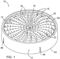
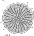
- FIGs 1-3 there is shown a filter 10, according to an example embodiment of the present invention, for filtering particles in a container of fluid.
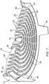
- Figures 4-7 show filter 10 according to a second example embodiment of the invention.
- Filter 10 comprises a flow director 12 and a skirt 14 coupled thereto.
- Flow director 12 comprises a hub 16, a plurality of radial blades 18, extending outwardly from hub 16, and a plurality of vanes 20, generally concentric or encircling hub 16.
- radial blades 18 intersect with concentric vanes 20 to form a grid 22 having a first face 24 (top face) and an opposed second face 26 (bottom face).
- Grid 22 extends to a perimeter 28.
- Radial blades 18 and concentric vanes 20 collectively define a plurality of openings 30 formed therebetween. Each opening 30 extends between first face 24 and second face 26. The cross-sectional area of each opening decreases from first face 24 to second face 26.
- filter 10 In use, filter 10 would typically be placed within a bucket or other such container with skirt 14 extending downwardly and supporting the filter from the bottom of the bucket or container.
- skirt 14 fits relatively tight or snug against the interior surface of the bucket forming in a sense somewhat of a seal between the interior wall of the bucket and the skirt.
- openings 30 will be oriented generally vertically such that fluid and dirt particles are permitted to flow through openings 30 from a positon above flow director 12 to a position below flow director 12 (details of which are discussed in greater detail below).
- the decrease in cross-sectional area of openings 30 within grid 22 helps to prevent particles from travelling from below flow director 12 upwardly past flow director 12 and into container 100 at a position above the flow director.
- the orientation, shape and position of the constituent parts of filter 10 help to direct fluid through the filter 10, and consequently within container 100.
- each concentric vane 20 has a top edge 32, adjacent first face 24, and a bottom edge 34, adjacent second face 26. Each concentric vane 20 is tapered such that top edge 32 is narrower than bottom edge 34.
- each concentric vane 20 comprises a pair of arm members joined together to form a V-shaped trough 36 having a closed end and an open end. The closed end of the trough forms top edge 32 and the open end of the trough forms bottom edge 34.
- V-shaped troughs 36 thus contributes to reducing the cross-sectional area of each opening 30 from first face 24 to second face 26.
- the arms of V-shaped troughs 36 may be formed at an angle of approximately 27°, however, other angles of taper may also be used. While the V-shaped troughs are shown to have hollow interiors, in an alternate embodiment, the troughs may be filled or solid.
- Each radial blade 18 has a top ridge 38, adjacent first face 24, and a bottom ridge 40, adjacent second face 26. Radial blades 18 may also be tapered such that top ridges 38 are narrower than their corresponding bottom ridges 40. However, as shown in the depicted embodiment, the degree of taper of radial blades 18 is typically much less than the degree of taper of concentric vane 20. For example, the degree of taper for radial blades 18 may be approximately 2°.
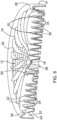
- the tapering of concentric vanes 20 (and radial blades 18 if indeed they are tapered), and the associated decrease in cross-sectional area of openings 30, helps to increase the velocity of fluid as it travels downwardly in the container past flow director 12. (see the dashed lines in Figs 5 and 8 ). That is, as a wash mitt, etc is thrust into the bucket there will be imparted a downwardly directed force upon the fluid within the bucket such that fluid will be pushed downwardly through openings 30. As described in detail below, fluid will simultaneously also flow upwardly from below flow director 12 to above the flow director.
- openings 30 in the flow director As fluid moves in a downward direction through openings 30 in the flow director a type of venturi effect is created with an increase in flow velocity, or movement of fluid through openings 30, thus helping to prevent fluid and particles from travelling back up through the openings. Further, the relatively smaller cross-sectional area of openings 30 at second face 26 provides a smaller area through which particles below flow director 12 may pass, thereby further helping to prevent dirt particles from travelling upwardly within the bucket from below flow director 12.
- Radial blades 18 may extend outwardly from first face 24 beyond concentric vanes 20.
- top ridges 38 of radial blades 18 extend further from second face 26 than do top edges 32 of concentric vanes 20.
- the height of radial blades 18 from second face 26 is greater than the height of concentric vanes 20 from second face 26.
- the distance between any two adjacent radial blades 18 in a horizontal plane tapers towards hub 16 (See Figure 2 for example). This tapering between adjacent radial blades can help to direct fluid towards hub 16 and increase the velocity of fluid as it travels towards hub 16, such as when a wash mitt etc. is thrust into container 100.
- the tapering radial blades creates a restriction, something akin to a venturi, such that the velocity of fluid travelling towards hub 16 tends to increase.
- a portion of the fluid will at times also tend to travel over top edges 32 of concentric vanes 20 (see the dashed arrows in Figure 5 ), creating a tumbling effect.
- a portion of that tumbling fluid will generally fall through openings 30, carrying with it any entrained dirt particles.
- a larger volume of fluid may flow through flow director 12 proximate hub 16, from first face 24 towards second face 26, than through flow director 12 proximate perimeter 28, when a wash mitt, etc is plunged into the bucket.
- the dashed arrows in Figure 5 represent some examples of the flow of fluid about filter 10.
- Skirt 14 is coupled to, or integral with, perimeter 28 of flow director 12. In the depicted embodiments, the outermost ends of radial blades 18 are fixed to skirt 14. As shown in Figure 8 , skirt 14 may be configured to maintain flow director 12 in spaced relation from a bottom 102 of a container 100. Skirt 14 thus compartmentalizes container 100 so that flow director 12 acts as a divider between fluid 104 above and below the flow director. Skirt 14 in both depicted embodiments has an increasing diameter as it extends away from second face 26, forming sloped sides. In certain embodiments, skirt 14 may extend 2° from perpendicular from first face 24, however, other degrees of taper may also be used.
- Skirt 14 may be formed from a pliable plastic that is deformable to accommodate the interior walls of different sized containers.
- skirt 14 extends around perimeter 28 to an outer rim 44.
- Skirt 14 in Figs 1-3 further includes notches 46 positioned at outer rim 44 to allow the skirt to deform and sit within containers of different sizes.
- skirt 14 includes a plurality of legs 48 extending away from second face 26. Similar to the first embodiment, legs 48 are also pliable to allow filter 10 to sit within containers of different sizes.
- skirt 14 and an outermost concentric vane 52 are configured and spaced apart to form a fluid return region 54 therebetween, and to form fluid return passageways 56.
- Fluid return passageways 56 thus allow a portion of the fluid flowing through fluid return region 54 to flow to a position above flow director 12 and a portion of the fluid in fluid return region 54 to return to bottom 102 of container 100 below flow director 12.
- outermost concentric vane 52 extends generally perpendicularly from second face 26 to form a bottom rim 58 of fluid return passageways 56.
- outermost concentric vane 52 is shown to have a somewhat smaller height than the adjacent concentric vane.
- Skirt 14 in turn, extends above and around fluid return region 54, reaching an apex, before extending downwardly back towards outermost concentric vane 52, thereby forming a top rim 60 of fluid return passageways 56.
- bottom rim 58, top rim 60 and radial blades 18 collectively define the edges of fluid return passageways 56.
- bottom rim 58 and top rim 60 will each tend to exert drag on adjacent fluid as fluid travels through fluid return passageways 56. Drag exerted on the fluid by bottom rim 58 helps to direct heavier or particle-laden fluid through adjacent opening 30 back under flow director 12 as indicated by the dashed arrows in Figures 5 and 8 . Drag exerted on the fluid by top rim 60 will also thus help to direct lighter, clean fluid away from bottom 102 above flow director 12 as indicated by the dashed arrows. The relative densities of the dirty or particle laden fluid vs cleaner fluid will also impact its particular path with more dense, particle laden fluid tending to fall back through openings 30 that are closest to skirt 14.
- radial blades 18 may be curved in two ways. First, as best shown in Figure 2 , radial blades 18 longitudinally arc in a common direction in a horizontal plane as they extend from skirt 14 towards hub 16, forming a fan-like configuration. This collective arcing of radial blades 18 may assist in imparting a slight rotational force to the fluid as it travels towards and through flow director 12.
- Top ridges 38 of radial blades 18 also undulate in a vertical plane from perimeter 28 to hub 16. For example, as best seen in Figs 5 and 6 , the height of radial blades 18 from second face 26 increases as they extend from perimeter 28, before decreasing as they reach hub 16. In other applications, radial blades 18 may longitudinally extend from hub 16 in a linear fashion and/or the height of top ridges 38 may stay generally constant as they end from perimeter 28 to hub 16.
- top edge 32 of concentric vanes 20 and top ridges 38 of radial blades 18 may be relatively narrow (for example 0.04 inches in width), and in the depicted embodiments, rounded. In this manner, particles of dirt will not be inclined to collect on top edge 32 of concentric vanes 20 and top ridges 38 of radial blades 18, and will tend to fall through openings 30. Further, the rounded nature of top edge 32 of concentric vanes 20 and top ridges 38 of radial blades 18 allows the user to rub or scrub the wash mitt, sponge or cloth, over first face 24 of flow director 12 without damaging the mitt, sponge or washcloth.
- gripping portions 50 may be situated about hub 16. Gripping portions 50 may comprise a ledge or finger holes which a user may grip in order to lift filter 10 from container 100 after use.
- the filter may instead be formed into different shapes, including a variety of different polygonal shapes or an asymmetrical rounded shape.
- radial blades 18 and concentric vanes 20 are shown to be orientated generally perpendicular to one another, extending generally perpendicularly away from second face 26 towards first face 24.
- radial blades 18 and/or concentric vanes 20 may be orientated at an angle relative to one another, or they may extend at an angle away from second face 26.
- the angled orientation of radial blades 18 may help to further impart motion to the fluid as fluid travels from above flow director 12 to below flow director 12.
- the angled orientation of concentric vanes 20 may help to further direct fluid towards hub 16 as fluid travels from above flow director 12 to below flow director 12
Landscapes
- Chemical & Material Sciences (AREA)
- Chemical Kinetics & Catalysis (AREA)
- Filtration Of Liquid (AREA)
- Filtering Of Dispersed Particles In Gases (AREA)
- Containers And Packaging Bodies Having A Special Means To Remove Contents (AREA)
Claims (4)
- Filter (10) zum Filtern von Partikeln in einem Behälter (100) für Fluid, wobei der Filter (10) umfasst:einen Strömungsführer (12), umfassend eine Nabe (16), eine Vielzahl von radialen Blättern (18), die sich von der Nabe (16) erstrecken, und eine Vielzahl von Schaufeln (20), die konzentrisch um die Nabe (16) sind, wobei sich die Blätter (18) und die Schaufeln (20) schneiden, um ein Gitter zu bilden, das eine erste Fläche (24), eine gegenüberliegende zweite Fläche (26) und einen Umfang (28) aufweist, wobei die radialen Blätter (18) und die konzentrischen Schaufeln (20) gemeinsam eine Vielzahl von dazwischen gebildeten Öffnungen (30) definieren, wobei sich jede Öffnung (30) zwischen der ersten Fläche (24) und der zweiten Fläche (26) erstreckt, wo ein Querschnittsbereich jeder Öffnung (30) von der ersten Fläche (24) zu der zweiten Fläche (26) hin abnimmt, undeine Randleiste (14), die an den Umfang (28) des Strömungsführers (12) gekoppelt ist, um den Strömungsführer in Bezug auf einen Boden des Behälters (100) beabstandet zu halten, wobei die Randleiste (14) den Behälter derart unterteilt, dass der Strömungsführer (12) als Trennelement zwischen Fluid oberhalb und unterhalb des Strömungsführers (12) fungiert,wobei die Randleiste (14) und eine äußerste konzentrische Schaufel (52) voneinander beabstandet sind, um dazwischen einen Fluidrückflussbereich (54) zu bilden, wobei der Fluidrückflussbereich (54) Fluidrückflussdurchgänge (56) beinhaltet, die ermöglichen, dass zu dem Fluidrückflussbereich (54) geführtes Fluid von einer Position unterhalb des Strömungsführers (12) zu einer Position oberhalb des Strömungsführers (12) strömt,wobei die Abnahme des Querschnittsbereichs der Öffnungen (30) im Gitter dazu beiträgt zu verhindern, dass Partikel von einer Position unterhalb des Strömungsführers (12) zu einer Position oberhalb des Strömungsführers (12) wandern, undwobei die Fluidrückflussdurchgänge (56) einen unteren Rand (58), der von der äußersten konzentrischen Schaufel (52) gebildet wird, und einen oberen Rand (60), der von der Randleiste (14) gebildet wird, aufweisen, sodass bei einer Wanderung von Fluid nach oben durch die Fluidrückflussdurchgänge (56) Zugkraft, die von dem unteren Rand (58) auf das Fluid ausgeübt wird, dazu beiträgt, Fluid nach unten zurück durch den Strömungsführer (12) zu führen.
- Filter (10) nach Anspruch 1, wobei die Randleiste (14) einen zunehmenden Durchmesser aufweist, während sie sich weg von der zweiten Fläche (26) erstreckt, wobei die Randleiste (14) aus einem Material gebildet ist, das verformbar ist, um Wände von Behältern aufzunehmen, die unterschiedliche Innenabmessungen aufweisen.
- Filter (10) nach Anspruch 2, wobei die Randleiste (14) Kerben (46) beinhaltet, um der Randleiste (14) zu ermöglichen, sich beim Aufnehmen von Behältern mit unterschiedlichen Innenabmessungen zu verformen.
- Filter (10) nach Anspruch 2, wobei die Randleiste (14) einen oder mehrere Schenkel (48) umfasst, die sich weg von der zweiten Fläche (26) erstrecken, wobei die Schenkel (48) biegbar sind, um ein Aufnehmen von Behältern mit unterschiedlichen Innenabmessungen zu ermöglichen.
Applications Claiming Priority (2)
| Application Number | Priority Date | Filing Date | Title |
|---|---|---|---|
| US201862658194P | 2018-04-16 | 2018-04-16 | |
| PCT/CA2019/050398 WO2019200456A1 (en) | 2018-04-16 | 2019-04-03 | Wash bucket dirt filter |
Publications (4)
| Publication Number | Publication Date |
|---|---|
| EP3781285A1 EP3781285A1 (de) | 2021-02-24 |
| EP3781285A4 EP3781285A4 (de) | 2022-01-05 |
| EP3781285B1 true EP3781285B1 (de) | 2023-06-07 |
| EP3781285C0 EP3781285C0 (de) | 2023-06-07 |
Family
ID=68240595
Family Applications (1)
| Application Number | Title | Priority Date | Filing Date |
|---|---|---|---|
| EP19788723.5A Active EP3781285B1 (de) | 2018-04-16 | 2019-04-03 | Schmutzfilter für wascheimer |
Country Status (6)
| Country | Link |
|---|---|
| US (1) | US11351487B2 (de) |
| EP (1) | EP3781285B1 (de) |
| KR (1) | KR102764408B1 (de) |
| CN (1) | CN112020386B (de) |
| CA (1) | CA3096525A1 (de) |
| WO (1) | WO2019200456A1 (de) |
Families Citing this family (2)
| Publication number | Priority date | Publication date | Assignee | Title |
|---|---|---|---|---|
| CA3086995A1 (en) | 2019-07-25 | 2021-01-25 | Nordica Plastics Ltd. | Wash device, assembly, and system thereof |
| US20260097338A1 (en) * | 2024-10-09 | 2026-04-09 | Brian P. Felker | Portable microplastic filter stand |
Family Cites Families (14)
| Publication number | Priority date | Publication date | Assignee | Title |
|---|---|---|---|---|
| US7249344B1 (en) * | 1996-10-31 | 2007-07-24 | Citicorp Development Center, Inc. | Delivery of financial services to remote devices |
| JPH1156734A (ja) * | 1997-08-13 | 1999-03-02 | Hiroshi Inoue | バケツの中間網底及びその専用バケツ |
| US6000094A (en) * | 1998-05-07 | 1999-12-14 | Scot Young Research, Inc. | Replaceable filter for use in cleaning buckets |
| AU5122999A (en) | 1998-07-23 | 2000-02-14 | Dreison International, Inc. | Air pre-cleaner |
| US6761271B1 (en) * | 2001-06-25 | 2004-07-13 | Lynn J. Cresswell | Rinse screen for a water bucket |
| US7025880B2 (en) | 2002-01-24 | 2006-04-11 | Lamb Douglas R | Fluid receptacle and filter system |
| US8042215B2 (en) * | 2008-06-09 | 2011-10-25 | Thibault Richard R | Cleaning system for removing abrading material |
| CN101481174B (zh) | 2009-02-10 | 2010-12-29 | 天津市天水环保设计工程有限公司 | 可连续在线更新动态膜的v形槽式微网组件及应用方法 |
| HUP0900716A2 (en) * | 2009-11-17 | 2011-07-28 | Jozsef Bereznai | Filter for separating solids from fluid |
| US9192279B1 (en) * | 2011-04-01 | 2015-11-24 | Chris Valle | Container system for washing cars |
| US8657928B2 (en) * | 2011-07-29 | 2014-02-25 | The Sy-Klone Company | Versatile compact air precleaner, air cleaning method and disposable air filter cartridge for air precleaner |
| USD669155S1 (en) * | 2011-09-19 | 2012-10-16 | 3M Innovative Properties Company | Filtration capsule |
| USD718844S1 (en) * | 2013-03-11 | 2014-12-02 | Blucher Metal A/S | Drain grating |
| US9861247B2 (en) * | 2015-09-09 | 2018-01-09 | Smart, Inc. | Particle trap/filter and systems related thereto |
-
2019
- 2019-04-03 WO PCT/CA2019/050398 patent/WO2019200456A1/en not_active Ceased
- 2019-04-03 CN CN201980026236.3A patent/CN112020386B/zh active Active
- 2019-04-03 KR KR1020207030257A patent/KR102764408B1/ko active Active
- 2019-04-03 US US17/046,174 patent/US11351487B2/en active Active
- 2019-04-03 EP EP19788723.5A patent/EP3781285B1/de active Active
- 2019-04-03 CA CA3096525A patent/CA3096525A1/en active Pending
Also Published As
| Publication number | Publication date |
|---|---|
| KR102764408B1 (ko) | 2025-02-05 |
| WO2019200456A1 (en) | 2019-10-24 |
| CA3096525A1 (en) | 2019-10-24 |
| KR20210003112A (ko) | 2021-01-11 |
| EP3781285A1 (de) | 2021-02-24 |
| EP3781285A4 (de) | 2022-01-05 |
| CN112020386B (zh) | 2022-07-15 |
| CN112020386A (zh) | 2020-12-01 |
| US20210023484A1 (en) | 2021-01-28 |
| EP3781285C0 (de) | 2023-06-07 |
| US11351487B2 (en) | 2022-06-07 |
Similar Documents
| Publication | Publication Date | Title |
|---|---|---|
| EP3781285B1 (de) | Schmutzfilter für wascheimer | |
| US4240568A (en) | Attachment for liquid carrying container | |
| US5027973A (en) | Container having integrally formed bail hinge and reinforcing ring | |
| JP4750142B2 (ja) | ヘアキャッチャー | |
| US9861247B2 (en) | Particle trap/filter and systems related thereto | |
| US3451577A (en) | Egg tray construction | |
| EP2675718B1 (de) | Durchflussregelungsvorrichtung für einen behälter | |
| JPS588849B2 (ja) | 再使用可能なコ−ヒ−フイルタ | |
| RU2516410C2 (ru) | Устройство блендера, содержащее емкость | |
| US20140251890A1 (en) | Colander-bowl assembly | |
| KR101137102B1 (ko) | 싸이클론 분리기 | |
| KR20230067663A (ko) | 습식 청소 장치 | |
| JP2018053695A (ja) | へアキャッチャー | |
| JP4169475B2 (ja) | 遠心分離装置 | |
| JP2022520385A (ja) | 水から廃棄物を収集するための装置および装置のための分離装置 | |
| JP4840267B2 (ja) | ヘアキャッチャー | |
| US6161701A (en) | Separator | |
| JP3212852U (ja) | 流出防止弁 | |
| US755832A (en) | Dish-washer. | |
| US582576A (en) | Mucilage-bottle | |
| JP2001178639A (ja) | 水流式洗米機又は穀物洗い機 | |
| JPS6321300Y2 (de) | ||
| EP3282911B1 (de) | Beutelloser staubsauger | |
| US1570321A (en) | Skimming spoon | |
| US11083359B2 (en) | Grid device |
Legal Events
| Date | Code | Title | Description |
|---|---|---|---|
| STAA | Information on the status of an ep patent application or granted ep patent |
Free format text: STATUS: THE INTERNATIONAL PUBLICATION HAS BEEN MADE |
|
| PUAI | Public reference made under article 153(3) epc to a published international application that has entered the european phase |
Free format text: ORIGINAL CODE: 0009012 |
|
| STAA | Information on the status of an ep patent application or granted ep patent |
Free format text: STATUS: REQUEST FOR EXAMINATION WAS MADE |
|
| 17P | Request for examination filed |
Effective date: 20201116 |
|
| AK | Designated contracting states |
Kind code of ref document: A1 Designated state(s): AL AT BE BG CH CY CZ DE DK EE ES FI FR GB GR HR HU IE IS IT LI LT LU LV MC MK MT NL NO PL PT RO RS SE SI SK SM TR |
|
| AX | Request for extension of the european patent |
Extension state: BA ME |
|
| DAV | Request for validation of the european patent (deleted) | ||
| DAX | Request for extension of the european patent (deleted) | ||
| A4 | Supplementary search report drawn up and despatched |
Effective date: 20211202 |
|
| RIC1 | Information provided on ipc code assigned before grant |
Ipc: B01D 35/143 20060101ALI20211126BHEP Ipc: B01D 35/02 20060101AFI20211126BHEP |
|
| GRAP | Despatch of communication of intention to grant a patent |
Free format text: ORIGINAL CODE: EPIDOSNIGR1 |
|
| STAA | Information on the status of an ep patent application or granted ep patent |
Free format text: STATUS: GRANT OF PATENT IS INTENDED |
|
| INTG | Intention to grant announced |
Effective date: 20221128 |
|
| GRAS | Grant fee paid |
Free format text: ORIGINAL CODE: EPIDOSNIGR3 |
|
| GRAA | (expected) grant |
Free format text: ORIGINAL CODE: 0009210 |
|
| STAA | Information on the status of an ep patent application or granted ep patent |
Free format text: STATUS: THE PATENT HAS BEEN GRANTED |
|
| AK | Designated contracting states |
Kind code of ref document: B1 Designated state(s): AL AT BE BG CH CY CZ DE DK EE ES FI FR GB GR HR HU IE IS IT LI LT LU LV MC MK MT NL NO PL PT RO RS SE SI SK SM TR |
|
| REG | Reference to a national code |
Ref country code: GB Ref legal event code: FG4D |
|
| REG | Reference to a national code |
Ref country code: CH Ref legal event code: EP Ref country code: AT Ref legal event code: REF Ref document number: 1573251 Country of ref document: AT Kind code of ref document: T Effective date: 20230615 |
|
| REG | Reference to a national code |
Ref country code: DE Ref legal event code: R096 Ref document number: 602019030492 Country of ref document: DE |
|
| U01 | Request for unitary effect filed |
Effective date: 20230621 |
|
| U07 | Unitary effect registered |
Designated state(s): AT BE BG DE DK EE FI FR IT LT LU LV MT NL PT SE SI Effective date: 20230628 |
|
| REG | Reference to a national code |
Ref country code: LT Ref legal event code: MG9D |
|
| PG25 | Lapsed in a contracting state [announced via postgrant information from national office to epo] |
Ref country code: NO Free format text: LAPSE BECAUSE OF FAILURE TO SUBMIT A TRANSLATION OF THE DESCRIPTION OR TO PAY THE FEE WITHIN THE PRESCRIBED TIME-LIMIT Effective date: 20230907 Ref country code: ES Free format text: LAPSE BECAUSE OF FAILURE TO SUBMIT A TRANSLATION OF THE DESCRIPTION OR TO PAY THE FEE WITHIN THE PRESCRIBED TIME-LIMIT Effective date: 20230607 |
|
| PG25 | Lapsed in a contracting state [announced via postgrant information from national office to epo] |
Ref country code: RS Free format text: LAPSE BECAUSE OF FAILURE TO SUBMIT A TRANSLATION OF THE DESCRIPTION OR TO PAY THE FEE WITHIN THE PRESCRIBED TIME-LIMIT Effective date: 20230607 Ref country code: HR Free format text: LAPSE BECAUSE OF FAILURE TO SUBMIT A TRANSLATION OF THE DESCRIPTION OR TO PAY THE FEE WITHIN THE PRESCRIBED TIME-LIMIT Effective date: 20230607 Ref country code: GR Free format text: LAPSE BECAUSE OF FAILURE TO SUBMIT A TRANSLATION OF THE DESCRIPTION OR TO PAY THE FEE WITHIN THE PRESCRIBED TIME-LIMIT Effective date: 20230908 |
|
| PG25 | Lapsed in a contracting state [announced via postgrant information from national office to epo] |
Ref country code: SK Free format text: LAPSE BECAUSE OF FAILURE TO SUBMIT A TRANSLATION OF THE DESCRIPTION OR TO PAY THE FEE WITHIN THE PRESCRIBED TIME-LIMIT Effective date: 20230607 |
|
| PG25 | Lapsed in a contracting state [announced via postgrant information from national office to epo] |
Ref country code: IS Free format text: LAPSE BECAUSE OF FAILURE TO SUBMIT A TRANSLATION OF THE DESCRIPTION OR TO PAY THE FEE WITHIN THE PRESCRIBED TIME-LIMIT Effective date: 20231007 |
|
| PG25 | Lapsed in a contracting state [announced via postgrant information from national office to epo] |
Ref country code: SM Free format text: LAPSE BECAUSE OF FAILURE TO SUBMIT A TRANSLATION OF THE DESCRIPTION OR TO PAY THE FEE WITHIN THE PRESCRIBED TIME-LIMIT Effective date: 20230607 Ref country code: SK Free format text: LAPSE BECAUSE OF FAILURE TO SUBMIT A TRANSLATION OF THE DESCRIPTION OR TO PAY THE FEE WITHIN THE PRESCRIBED TIME-LIMIT Effective date: 20230607 Ref country code: RO Free format text: LAPSE BECAUSE OF FAILURE TO SUBMIT A TRANSLATION OF THE DESCRIPTION OR TO PAY THE FEE WITHIN THE PRESCRIBED TIME-LIMIT Effective date: 20230607 Ref country code: IS Free format text: LAPSE BECAUSE OF FAILURE TO SUBMIT A TRANSLATION OF THE DESCRIPTION OR TO PAY THE FEE WITHIN THE PRESCRIBED TIME-LIMIT Effective date: 20231007 Ref country code: CZ Free format text: LAPSE BECAUSE OF FAILURE TO SUBMIT A TRANSLATION OF THE DESCRIPTION OR TO PAY THE FEE WITHIN THE PRESCRIBED TIME-LIMIT Effective date: 20230607 |
|
| PG25 | Lapsed in a contracting state [announced via postgrant information from national office to epo] |
Ref country code: PL Free format text: LAPSE BECAUSE OF FAILURE TO SUBMIT A TRANSLATION OF THE DESCRIPTION OR TO PAY THE FEE WITHIN THE PRESCRIBED TIME-LIMIT Effective date: 20230607 |
|
| REG | Reference to a national code |
Ref country code: DE Ref legal event code: R097 Ref document number: 602019030492 Country of ref document: DE |
|
| PLBE | No opposition filed within time limit |
Free format text: ORIGINAL CODE: 0009261 |
|
| STAA | Information on the status of an ep patent application or granted ep patent |
Free format text: STATUS: NO OPPOSITION FILED WITHIN TIME LIMIT |
|
| 26N | No opposition filed |
Effective date: 20240308 |
|
| U20 | Renewal fee for the european patent with unitary effect paid |
Year of fee payment: 6 Effective date: 20240415 |
|
| PG25 | Lapsed in a contracting state [announced via postgrant information from national office to epo] |
Ref country code: MC Free format text: LAPSE BECAUSE OF FAILURE TO SUBMIT A TRANSLATION OF THE DESCRIPTION OR TO PAY THE FEE WITHIN THE PRESCRIBED TIME-LIMIT Effective date: 20230607 |
|
| PG25 | Lapsed in a contracting state [announced via postgrant information from national office to epo] |
Ref country code: MC Free format text: LAPSE BECAUSE OF FAILURE TO SUBMIT A TRANSLATION OF THE DESCRIPTION OR TO PAY THE FEE WITHIN THE PRESCRIBED TIME-LIMIT Effective date: 20230607 |
|
| REG | Reference to a national code |
Ref country code: CH Ref legal event code: PL |
|
| PG25 | Lapsed in a contracting state [announced via postgrant information from national office to epo] |
Ref country code: CH Free format text: LAPSE BECAUSE OF NON-PAYMENT OF DUE FEES Effective date: 20240430 |
|
| PG25 | Lapsed in a contracting state [announced via postgrant information from national office to epo] |
Ref country code: IE Free format text: LAPSE BECAUSE OF NON-PAYMENT OF DUE FEES Effective date: 20240403 |
|
| U20 | Renewal fee for the european patent with unitary effect paid |
Year of fee payment: 7 Effective date: 20250424 |
|
| PGFP | Annual fee paid to national office [announced via postgrant information from national office to epo] |
Ref country code: GB Payment date: 20250417 Year of fee payment: 7 |
|
| PG25 | Lapsed in a contracting state [announced via postgrant information from national office to epo] |
Ref country code: CY Free format text: LAPSE BECAUSE OF FAILURE TO SUBMIT A TRANSLATION OF THE DESCRIPTION OR TO PAY THE FEE WITHIN THE PRESCRIBED TIME-LIMIT; INVALID AB INITIO Effective date: 20190403 |
|
| PG25 | Lapsed in a contracting state [announced via postgrant information from national office to epo] |
Ref country code: HU Free format text: LAPSE BECAUSE OF FAILURE TO SUBMIT A TRANSLATION OF THE DESCRIPTION OR TO PAY THE FEE WITHIN THE PRESCRIBED TIME-LIMIT; INVALID AB INITIO Effective date: 20190403 |
|
| PG25 | Lapsed in a contracting state [announced via postgrant information from national office to epo] |
Ref country code: TR Free format text: LAPSE BECAUSE OF FAILURE TO SUBMIT A TRANSLATION OF THE DESCRIPTION OR TO PAY THE FEE WITHIN THE PRESCRIBED TIME-LIMIT Effective date: 20230607 |