EP3781009B1 - Orbitale einbürstenmaschine zur behandlung von böden - Google Patents
Orbitale einbürstenmaschine zur behandlung von böden Download PDFInfo
- Publication number
- EP3781009B1 EP3781009B1 EP19713823.3A EP19713823A EP3781009B1 EP 3781009 B1 EP3781009 B1 EP 3781009B1 EP 19713823 A EP19713823 A EP 19713823A EP 3781009 B1 EP3781009 B1 EP 3781009B1
- Authority
- EP
- European Patent Office
- Prior art keywords
- footing
- motor
- machine
- floor
- machine according
- Prior art date
- Legal status (The legal status is an assumption and is not a legal conclusion. Google has not performed a legal analysis and makes no representation as to the accuracy of the status listed.)
- Active
Links
Images


Classifications
-
- A—HUMAN NECESSITIES
- A47—FURNITURE; DOMESTIC ARTICLES OR APPLIANCES; COFFEE MILLS; SPICE MILLS; SUCTION CLEANERS IN GENERAL
- A47L—DOMESTIC WASHING OR CLEANING; SUCTION CLEANERS IN GENERAL
- A47L11/00—Machines for cleaning floors, carpets, furniture, walls, or wall coverings
- A47L11/02—Floor surfacing or polishing machines
- A47L11/10—Floor surfacing or polishing machines motor-driven
- A47L11/12—Floor surfacing or polishing machines motor-driven with reciprocating or oscillating tools
-
- A—HUMAN NECESSITIES
- A47—FURNITURE; DOMESTIC ARTICLES OR APPLIANCES; COFFEE MILLS; SPICE MILLS; SUCTION CLEANERS IN GENERAL
- A47L—DOMESTIC WASHING OR CLEANING; SUCTION CLEANERS IN GENERAL
- A47L11/00—Machines for cleaning floors, carpets, furniture, walls, or wall coverings
- A47L11/02—Floor surfacing or polishing machines
- A47L11/10—Floor surfacing or polishing machines motor-driven
- A47L11/14—Floor surfacing or polishing machines motor-driven with rotating tools
- A47L11/16—Floor surfacing or polishing machines motor-driven with rotating tools the tools being disc brushes
- A47L11/162—Floor surfacing or polishing machines motor-driven with rotating tools the tools being disc brushes having only a single disc brush
-
- A—HUMAN NECESSITIES
- A47—FURNITURE; DOMESTIC ARTICLES OR APPLIANCES; COFFEE MILLS; SPICE MILLS; SUCTION CLEANERS IN GENERAL
- A47L—DOMESTIC WASHING OR CLEANING; SUCTION CLEANERS IN GENERAL
- A47L11/00—Machines for cleaning floors, carpets, furniture, walls, or wall coverings
- A47L11/28—Floor-scrubbing machines, motor-driven
- A47L11/282—Floor-scrubbing machines, motor-driven having rotary tools
- A47L11/283—Floor-scrubbing machines, motor-driven having rotary tools the tools being disc brushes
-
- A—HUMAN NECESSITIES
- A47—FURNITURE; DOMESTIC ARTICLES OR APPLIANCES; COFFEE MILLS; SPICE MILLS; SUCTION CLEANERS IN GENERAL
- A47L—DOMESTIC WASHING OR CLEANING; SUCTION CLEANERS IN GENERAL
- A47L11/00—Machines for cleaning floors, carpets, furniture, walls, or wall coverings
- A47L11/40—Parts or details of machines not provided for in groups A47L11/02 - A47L11/38, or not restricted to one of these groups, e.g. handles, arrangements of switches, skirts, buffers, levers
- A47L11/4036—Parts or details of the surface treating tools
- A47L11/4038—Disk shaped surface treating tools
-
- A—HUMAN NECESSITIES
- A47—FURNITURE; DOMESTIC ARTICLES OR APPLIANCES; COFFEE MILLS; SPICE MILLS; SUCTION CLEANERS IN GENERAL
- A47L—DOMESTIC WASHING OR CLEANING; SUCTION CLEANERS IN GENERAL
- A47L11/00—Machines for cleaning floors, carpets, furniture, walls, or wall coverings
- A47L11/40—Parts or details of machines not provided for in groups A47L11/02 - A47L11/38, or not restricted to one of these groups, e.g. handles, arrangements of switches, skirts, buffers, levers
- A47L11/4052—Movement of the tools or the like perpendicular to the cleaning surface
-
- A—HUMAN NECESSITIES
- A47—FURNITURE; DOMESTIC ARTICLES OR APPLIANCES; COFFEE MILLS; SPICE MILLS; SUCTION CLEANERS IN GENERAL
- A47L—DOMESTIC WASHING OR CLEANING; SUCTION CLEANERS IN GENERAL
- A47L11/00—Machines for cleaning floors, carpets, furniture, walls, or wall coverings
- A47L11/40—Parts or details of machines not provided for in groups A47L11/02 - A47L11/38, or not restricted to one of these groups, e.g. handles, arrangements of switches, skirts, buffers, levers
- A47L11/4063—Driving means; Transmission means therefor
- A47L11/4069—Driving or transmission means for the cleaning tools
-
- A—HUMAN NECESSITIES
- A47—FURNITURE; DOMESTIC ARTICLES OR APPLIANCES; COFFEE MILLS; SPICE MILLS; SUCTION CLEANERS IN GENERAL
- A47L—DOMESTIC WASHING OR CLEANING; SUCTION CLEANERS IN GENERAL
- A47L11/00—Machines for cleaning floors, carpets, furniture, walls, or wall coverings
- A47L11/40—Parts or details of machines not provided for in groups A47L11/02 - A47L11/38, or not restricted to one of these groups, e.g. handles, arrangements of switches, skirts, buffers, levers
- A47L11/4072—Arrangement of castors or wheels
Definitions
- the present invention relates to an orbital single-brush machine for treating floors.
- Single-brush machines are known for treating floors, which are constituted by a chassis base, fitted with wheels, to which a movement handle is connected at the rear.
- the chassis base supports a brush below it, which acts on the floor and which is actuated in rotation by a motor fitted on the base.
- orbital single-brush machines are known on the market, in which the brush is actuated with a combined rotary and orbital motion which is transferred from the motor to the brush by way of a cam screw mechanism.
- the base is constituted by a pair of lateral supporting arms that extend parallel to the advancement direction of the machine and which, at their rear end, have wheels resting on the floor and, at their front end, oscillatingly support the motor and the kinematic mechanism that make it possible to actuate the brush with a combined rotary and orbital motion.
- orbital single-brush machines tend to transmit vibrations to the user.
- the aim of the present invention is to provide an orbital single-brush machine for treating floors that is capable of improving the known art in one or more of the above mentioned aspects.
- an object of the invention is to provide an orbital single-brush machine that, owing to its peculiar characteristics of construction, has reduced dimensions and weight or at least dimensions and weight that are similar to those of a traditional single-brush machine, and which at the same time can be easily maneuvered for any operator and is highly versatile.
- Another object of the invention is to provide an orbital single-brush machine that in terms of construction is simple to provide so that it can be easily used in various different application contexts.
- Another object of the invention is to provide an orbital single-brush machine that, as needed, can also be equipped with machining tools other than the normal brush that is typically used, without any degradation in the performance of the machine.
- Another object of the present invention is to provide an orbital single-brush machine that is capable of offering the maximum assurances of safety in its operation, preventing, or in any case considerably limiting, the possibility that vibrations or hazardous or harmful forces could be transmitted to the user.
- Another object of the invention is to provide an orbital single-brush machine that is highly reliable and which is competitive from an economic viewpoint as well.
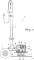
- the orbital single-brush machine generally designated by the reference numeral 1, comprises a chassis 2 which rests on the floor and is provided with at least one movement handle 3 in order to allow the chassis 2 to be moved on the floor by an operator.
- the chassis 2 is connected to a motor 4 which makes it possible to actuate, with combined rotary and orbital motion, a work tool 5 that acts on the floor, which can be constituted, for example, by a normal brush or, alternatively, also by a polishing pad or the like, according to the treatment to be carried out.
- the chassis 2 comprises a substantially plate-shaped first footing 6, which is, advantageously, spaced apart from the floor and is provided at the rear, with respect to the advancement direction of the machine, with at least one pair of wheels 7 resting on the floor, which are mutually opposite.
- the movement handle 3 is hinged in a lower region to the first footing 6.
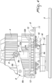
- the chassis 2 further comprises a substantially plate-shaped second footing 8, which supports the motor 4 and is arranged below the first footing 6 and is supported so that it can rotate freely by the first footing 6 about an oscillation axis 8a that is substantially parallel to the floor and substantially perpendicular to the advancement direction of the machine.
- the second footing 8 is freely pivoted to the first footing 6 about the oscillation axis 8a by way of a pair of hinges 9 which are mutually opposite with respect to the motor 4.
- shock absorbing means act between at least one portion of the first footing 6 and at least one portion of the second footing 8, and make it possible to attenuate the vibrations that otherwise would be transmitted to the first footing 6 and therefore to the handle 3 from the work tool 5, through the second footing 8.
- the second footing 8 supports means for kinematic connection, conventional, connecting the motor 4 with the work tool 5, which are adapted to give the work tool 5 a combined rotary and orbital motion, for example by way of a an eccentric transmission.
- the first footing 6 can have a plate-shaped portion 6a from which a pair of lateral supporting arms 6b protrudes forward with respect to the direction of advancement of the machine, to which and, in particular, to the free end of which, the second footing 8 is connected.
- the lateral supporting arms 6b can have a first portion, which extends starting from the plate-shaped portion 6a with an extension substantially horizontal or parallel to the floor and an inclined second portion, connected to the first portion, which extends upwards, proceeding toward the front end of the machine, to which the second footing 8 is pivoted by way of the hinges 9.
- the handle 3 in such embodiment, can be conveniently connected to the plate-shaped portion 6a, in a position interposed between the supporting wheels 7 and the lateral supporting arms 6b of the second footing 8.
- the second footing 8 comprises a lower plate 11, to which the motor 4 is fixed, preferably by way of bolts, and which is arranged on a plane that is substantially perpendicular to the axis of the shaft 4a of the motor 4.
- the lower plate 11 is connected to at least one upper structure 12, which is pivoted to the first footing 6 about the oscillation axis 8a. More specifically, there is a pair of upper structures 12 which are arranged laterally to the motor 4, on mutually opposite sides, with respect to a central plane of symmetry of the machine which is substantially perpendicular to the floor and which is substantially parallel to the advancement direction of the machine.
- connection between the lower plate 11 and each upper structure 12 is such as to allow a possibility of relative movement between the lower plate 11 and the upper structures 12 at least along a direction of motion that is substantially parallel to the axis of the shaft 4a of the motor 4.
- the lower plate 11 is slideable and guided in its movement relative to the upper structures 12 by at least one pair of guide rods 15, mutually opposite with respect to the motor 4, which extend downward from the upper structures 11 and substantially at right angles to the axis of the shaft 4a of the motor 4, passing through with play respective openings 11a which are defined at the peripheral region of the lower plate 11 and are advantageously lined, on their perimetric edge, by a grommet 20, made of elastically yielding material, such as rubber or the like.
- the above mentioned shock absorbing means comprise a plurality of vibration damping elements 13 which are interposed between the lower plate 11 and the upper structures 12.
- the vibration damping elements 13 are distributed along the peripheral region of the lower plate 11 so as to be arranged around the motor 4 and are each constituted by a substantially cylindrical body, optionally grooved i.e. provided with a circumferential hollow on its lateral surface, arranged, with its axis, substantially parallel to the direction of motion of the lower plate 11 with respect to the upper structures 12 and made of an elastically yielding material, preferably with a hardness substantially equal to 45 Shore.
- each one of the upper structures 12 comprises an oscillation arm 12a, which is hinged by way of a corresponding hinge 9 to the first footing 6 and, more precisely, to a corresponding lateral supporting arm 6b and which extends upward from a respective base element 12b, which is preferably C-shaped or shaped like a circular arc, so as to extend around the motor 4, and is constituted, for example, by a flat bar, which faces the lower plate 11 and acts as an abutment for the vibration damping elements 13.
- each vibration damping element 13 has, at its ends, two abutment plates 13a and 13b, which are arranged at right angles to the axis of the vibration damping element 13 and are made of a material with a greater rigidity than the cylindrical body of the vibration damping element 13, and which are passed through axially by a respective threaded hole 13c for the accommodation of fixing screws that make it possible to connect the ends of the vibration damping element 13 respectively to the lower plate 12 and to the base element 12b.
- the lower plate 11 is fixed in a downward region to an inertial mass 14, which increases the weight of the lower plate 11, by exerting an action thereupon that tends to keep them spaced apart downward from the upper structures 12, in order to ensure, under any condition, an optimal action of contact of the work tool 5 with the floor.
- such means for limiting the stroke comprise, advantageously, at least one stop element 16, which is arranged spaced apart downward from the upper structures 11 and which is engageable in abutment by the face of the lower plate 11 which is directed toward the floor, so as to limit the downward stroke of the lower plate 11 with respect to the upper structures 12 and thus define the maximum elongation that the vibration damping elements 13 can undergo.
- each one constituted by a washer 16a advantageously made of rigid material, such as for example a technopolymer, placed around a respective guide rod 15.
- the guide rods 15 can be, in particular, provided by respective screws 15a, which with their shank pass through corresponding through holes 18 defined in the base elements 12b of the upper structures 12 and which engage with their heads against the upper face of the base elements 12b, to which they are fixed by way of a lock nut 17, which is screwed along the screws 15a in order to engage the lower face of the base elements 12b, on the other side with respect to the heads of the screws 15a. Substantially at the end of the screws 15a opposite from their head, there is also a retaining nut 19 screwed on a respective washer 16a.
- each base element 12b there is a reinforcement element 21, similarly contoured, which is passed through, at the through holes 18, by corresponding holes 22 in which the lock nuts 17 are accommodated.
- first footing 6 and the motor 4 are accommodated within a single outer containment housing 25, which extends, conveniently, to also cover at least partially the second footing 8, so as to confer adequate protection and compactness on the machine.
- the operator once the motor 4 is activated, can maneuver the machine by way of the handle 3 over the floor so as to carry out the desired floor treatment by way of the action of the work tool 5.
- the motor 4, being supported by the second footing 8, which in turn is pivoted to the first footing 6, is free to rotate with respect to the first footing 6, thus enabling the work tool 5 to always remain completely in contact with the floor.
- the machine is capable of working correctly under any condition, i.e. with any type of floor and with any type of work tool 5, even if of a different height.
- any forces that would be transmitted from the work tool 5 to the handle 3 are attenuated, if not eliminated, by virtue of the presence of the shock absorbing means which act between the first and the second footing 6 and 8.
- the vibrations that come to be transmitted from the work tool 5 to the handle 3 are absorbed by the vibration damping elements 13 arranged between the lower plate 11 and the upper structures 12 of the second footing 8.
- the lower plate 11 is spaced apart upward from the stop elements 16, such that the stop elements 16 do not work and the weight of the motor 4 and of the inertial mass 14 is transmitted to the ground.
- the lower plate 11 When the operator has to lift the work tool 5 off the floor, the lower plate 11, by virtue of the weight of the motor 4 and of the inertial mass 14, tends to remain close to the ground, owing to its possibility to move with respect to the upper structures 12, with the risk that the vibration damping elements 12 could break owing to an excessive elongation under traction.
- the means for limiting the stroke of the lower plate 11 and, more specifically, the stop elements 16 make it possible to prevent this risk, by limiting the lengthening stroke of the vibration damping elements 13, through the contact between the stop elements 16 and the grommets 20 mounted on the lower plate 11.
- the invention fully achieves the intended aim and objects and in particular attention is drawn to the fact that the machine according to the invention, by virtue of the fact that it is structured with the first and the second footing, has a weight and space occupation that are comparable with those of a traditional non-orbital single-brush machine and are such as to make it easily usable even in a domestic context.
- the work tool is capable of always remaining in complete contact with the floor, which offers the machine according to the invention the capability to achieve a level of efficacy in the treatment carried out that is superior to any single-brush machine in the known art, with the additional advantage of being lighter and more compact as well as easy to maneuver on the floor, and without the need to apply a considerable force.
Landscapes
- Vibration Prevention Devices (AREA)
- Brushes (AREA)
Claims (7)
- Eine orbitale Einbürstenmaschine, die ein Fahrgestell (2) umfasst, das auf dem Boden aufliegt und mit mindestens einem Bewegungsgriff (3) ausgestattet ist, wobei ein Motor (4) mit dem Fahrgestell (2) verbunden und ausgebildet ist, um mit einer kombinierten drehenden und kreisenden Bewegung ein Arbeitswerkzeug (5) anzutreiben, das ausgebildet ist, um auf einzuwirken, wobei das Fahrgestell (2) eine erste Basis (6) umfasst, die zumindest teilweise im Wesentlichen plattenförmig und vom Boden beabstandet ist, und eine zweite Basis (8), die zumindest teilweise im Wesentlichen plattenförmig und unterhalb der ersten Basis (6) angeordnet und frei drehbar um eine Schwenkachse (8a), die im Wesentlichen parallel zum Boden und im Wesentlichen senkrecht zur Vorschubrichtung der Maschine ist, durch die erste Basis (6) gelagert ist; wobei die zweite Basis (6) den Motor (4) trägt; wobei Stoßdämpfungsmittel bereitgestellt sind, die zwischen mindestens einem Teil der ersten Basis (6) und mindestens einem Teil der zweiten Basis (8) wirken, wobei die zweite Basis (8) eine untere Befestigungsplatte (11) für den Motor (4) umfasst, die mit mindestens einer oberen Struktur (12) verbunden ist, welche drehgelenkig um die Schwenkachse (8a) mit der ersten Basis (6) verbunden ist; wobei die untere Platte (11) mit der mindestens einen oberen Struktur mit der Möglichkeit einer Relativbewegung mindestens in einer Bewegungsrichtung verbunden ist, die im Wesentlichen parallel zur Achse der Welle (4a) des Motors (4) ist; wobei die Stoßdämpfungsmittel eine Vielzahl von Vibrationsdämpfungselementen (13) umfassen, welche zwischen der unteren Platte (11) und der mindestens einen oberen Struktur (12) angeordnet sind; wobei die orbitale Einbürstenmaschine weiter Mittel umfasst, um den Hub der unteren Platte (11) mit Bezug auf die mindestens eine obere Struktur (12) in der Bewegungsrichtung zu begrenzen; dadurch gekennzeichnet, dass die Mittel zur Begrenzung des Hubs mindestens ein Anschlagelement (16) umfassen, welches nach unten von der mindestens einen oberen Struktur (12) beabstandet ist und durch Anschlag mit der unteren Platte (11) in Eingriff stehen kann.
- Die Maschine gemäß Anspruch 1, dadurch gekennzeichnet, dass die erste Basis (6) auf der Rückseite mit Bezug auf die Vorschubrichtung der Maschine angebracht ist, mit mindestens einem Paar einander gegenüberliegender Räder (7) zur Auflage auf dem Boden.
- Die Maschine gemäß einem oder mehreren der obigen Ansprüche, dadurch gekennzeichnet, dass die zweite Basis (8) über ein Paar von Scharnieren (9), die einander mit Bezug auf den Motor gegenüberliegen, frei drehgelenkig um die Schwenkachse (8a) mit der ersten Basis verbunden ist.
- Die Maschine gemäß einem oder mehreren der obigen Ansprüche, dadurch gekennzeichnet, dass der Motor (4) an der Seite der zweiten Basis (8) befestigt ist, die der ersten Basis (6) zugewandt ist.
- Die Maschine gemäß einem oder mehreren der obigen Ansprüche, dadurch gekennzeichnet, dass die erste Basis (6) einen plattenförmigen Abschnitt (6a) hat, von welchem ein Paar seitlicher Tragarme (6b) der zweiten Basis (8) mit Bezug auf die Vorschubrichtung der Maschine vorsteht.
- Die Maschine gemäß einem oder mehreren der obigen Ansprüche, dadurch gekennzeichnet, dass die zweite Basis (8) an ihrer dem Boden zugewandten Seite Mittel (10) zur kinematischen Verbindung zwischen dem Motor (4) und dem Arbeitswerkzeug (5) trägt, die ausgebildet sind, um dem Arbeitswerkzeug (5) eine kombinierte drehende und kreisende Bewegung zu verleihen.
- Die Maschine gemäß einem oder mehreren der obigen Ansprüche, dadurch gekennzeichnet, dass die Vibrationsdämpfungselemente (13) um den Motor (4) herum verteilt sind und jedes einen im Wesentlichen zylindrischen Körper aus elastisch biegsamem Material umfasst, der mit seiner Achse im Wesentlichen parallel zu der Bewegungsrichtung angeordnet ist.
Applications Claiming Priority (2)
| Application Number | Priority Date | Filing Date | Title |
|---|---|---|---|
| IT102018000004693A IT201800004693A1 (it) | 2018-04-19 | 2018-04-19 | Macchina monospazzola orbitale per il trattamento di pavimenti. |
| PCT/EP2019/058385 WO2019201602A1 (en) | 2018-04-19 | 2019-04-03 | Orbital single-brush machine for treating floors |
Publications (3)
| Publication Number | Publication Date |
|---|---|
| EP3781009A1 EP3781009A1 (de) | 2021-02-24 |
| EP3781009B1 true EP3781009B1 (de) | 2023-07-26 |
| EP3781009C0 EP3781009C0 (de) | 2023-07-26 |
Family
ID=63014774
Family Applications (1)
| Application Number | Title | Priority Date | Filing Date |
|---|---|---|---|
| EP19713823.3A Active EP3781009B1 (de) | 2018-04-19 | 2019-04-03 | Orbitale einbürstenmaschine zur behandlung von böden |
Country Status (4)
| Country | Link |
|---|---|
| US (1) | US11382476B2 (de) |
| EP (1) | EP3781009B1 (de) |
| IT (1) | IT201800004693A1 (de) |
| WO (1) | WO2019201602A1 (de) |
Families Citing this family (1)
| Publication number | Priority date | Publication date | Assignee | Title |
|---|---|---|---|---|
| SE2350052A1 (en) * | 2023-01-23 | 2024-07-24 | Husqvarna Ab | An improved floor scraper |
Family Cites Families (5)
| Publication number | Priority date | Publication date | Assignee | Title |
|---|---|---|---|---|
| US3055030A (en) * | 1961-03-22 | 1962-09-25 | Westinghouse Electric Corp | Tool attaching mechanism for a floor machine |
| US20060150362A1 (en) * | 2005-01-11 | 2006-07-13 | Alto U.S. Inc. | Orbital scrubber |
| WO2012064713A1 (en) * | 2010-11-08 | 2012-05-18 | William Randall Stuchlik | Random orbit disc scrubber |
| US9169893B2 (en) * | 2012-03-16 | 2015-10-27 | Susan Joyce Williamson | Vibration damper |
| US9700191B2 (en) * | 2015-04-13 | 2017-07-11 | Nilfisk, Inc. | Wheel lift assembly for floor treating apparatus |
-
2018
- 2018-04-19 IT IT102018000004693A patent/IT201800004693A1/it unknown
-
2019
- 2019-04-03 EP EP19713823.3A patent/EP3781009B1/de active Active
- 2019-04-03 US US17/048,810 patent/US11382476B2/en active Active
- 2019-04-03 WO PCT/EP2019/058385 patent/WO2019201602A1/en not_active Ceased
Also Published As
| Publication number | Publication date |
|---|---|
| IT201800004693A1 (it) | 2019-10-19 |
| US20210113046A1 (en) | 2021-04-22 |
| WO2019201602A1 (en) | 2019-10-24 |
| EP3781009A1 (de) | 2021-02-24 |
| US11382476B2 (en) | 2022-07-12 |
| EP3781009C0 (de) | 2023-07-26 |
Similar Documents
| Publication | Publication Date | Title |
|---|---|---|
| US4317314A (en) | Surface finishing machine | |
| US2867252A (en) | Debarking rotor having cushioned flails | |
| EP0593659A1 (de) | Haltevorrichtung | |
| EP3781009B1 (de) | Orbitale einbürstenmaschine zur behandlung von böden | |
| KR101466000B1 (ko) | 휴대용 그라인더 | |
| US20080000664A1 (en) | Hand-Held Power Tool Handle Device With a Vibration-Shielding Unit | |
| KR20190140594A (ko) | 핸드그라인더 홀더 | |
| US2124705A (en) | Surfacing machine | |
| KR101383136B1 (ko) | 바닥 타일 제거장치 | |
| US2268015A (en) | Floor polisher | |
| EP3599963B1 (de) | Orbitale einbürstenmaschine zur behandlung von böden | |
| KR20220056383A (ko) | 회전 작업대 | |
| EP3750463B1 (de) | Orbitale einbürstenmaschine | |
| KR101220896B1 (ko) | 이중벨트 툴 박스를 갖는 폴리싱 머신 | |
| CN216859295U (zh) | 一种立式气动减震打磨机 | |
| US2648856A (en) | Friction vibration damping means for floor polishers | |
| KR101901570B1 (ko) | 항공기의 조향장치 점검용 지지장치 | |
| US4947940A (en) | Apparatus and method for removing oil spots from a surface | |
| KR101895332B1 (ko) | 진동 저감 사이드 핸들 및 이를 포함하는 전동 공구 | |
| EP0294351B1 (de) | Maschinen Handgriff mit Vibrationsdämpfung | |
| US7686677B2 (en) | Floor treatment machine with wheel assembly | |
| US20160120386A1 (en) | Handle Assembly and Mobility System for Floor Cleaner | |
| CN215367196U (zh) | 一种建筑工程用地基压实设备 | |
| JP3000508U (ja) | 切断機 | |
| CN214814480U (zh) | 一种便于移动的数控搓牙机 |
Legal Events
| Date | Code | Title | Description |
|---|---|---|---|
| STAA | Information on the status of an ep patent application or granted ep patent |
Free format text: STATUS: UNKNOWN |
|
| STAA | Information on the status of an ep patent application or granted ep patent |
Free format text: STATUS: THE INTERNATIONAL PUBLICATION HAS BEEN MADE |
|
| PUAI | Public reference made under article 153(3) epc to a published international application that has entered the european phase |
Free format text: ORIGINAL CODE: 0009012 |
|
| STAA | Information on the status of an ep patent application or granted ep patent |
Free format text: STATUS: REQUEST FOR EXAMINATION WAS MADE |
|
| 17P | Request for examination filed |
Effective date: 20201103 |
|
| AK | Designated contracting states |
Kind code of ref document: A1 Designated state(s): AL AT BE BG CH CY CZ DE DK EE ES FI FR GB GR HR HU IE IS IT LI LT LU LV MC MK MT NL NO PL PT RO RS SE SI SK SM TR |
|
| AX | Request for extension of the european patent |
Extension state: BA ME |
|
| DAV | Request for validation of the european patent (deleted) | ||
| DAX | Request for extension of the european patent (deleted) | ||
| GRAP | Despatch of communication of intention to grant a patent |
Free format text: ORIGINAL CODE: EPIDOSNIGR1 |
|
| STAA | Information on the status of an ep patent application or granted ep patent |
Free format text: STATUS: GRANT OF PATENT IS INTENDED |
|
| INTG | Intention to grant announced |
Effective date: 20230220 |
|
| GRAS | Grant fee paid |
Free format text: ORIGINAL CODE: EPIDOSNIGR3 |
|
| GRAA | (expected) grant |
Free format text: ORIGINAL CODE: 0009210 |
|
| STAA | Information on the status of an ep patent application or granted ep patent |
Free format text: STATUS: THE PATENT HAS BEEN GRANTED |
|
| AK | Designated contracting states |
Kind code of ref document: B1 Designated state(s): AL AT BE BG CH CY CZ DE DK EE ES FI FR GB GR HR HU IE IS IT LI LT LU LV MC MK MT NL NO PL PT RO RS SE SI SK SM TR |
|
| REG | Reference to a national code |
Ref country code: CH Ref legal event code: EP |
|
| REG | Reference to a national code |
Ref country code: IE Ref legal event code: FG4D |
|
| REG | Reference to a national code |
Ref country code: DE Ref legal event code: R096 Ref document number: 602019033493 Country of ref document: DE |
|
| U01 | Request for unitary effect filed |
Effective date: 20230823 |
|
| U07 | Unitary effect registered |
Designated state(s): AT BE BG DE DK EE FI FR IT LT LU LV MT NL PT SE SI Effective date: 20230831 |
|
| REG | Reference to a national code |
Ref country code: LT Ref legal event code: MG9D |
|
| PG25 | Lapsed in a contracting state [announced via postgrant information from national office to epo] |
Ref country code: GR Free format text: LAPSE BECAUSE OF FAILURE TO SUBMIT A TRANSLATION OF THE DESCRIPTION OR TO PAY THE FEE WITHIN THE PRESCRIBED TIME-LIMIT Effective date: 20231027 |
|
| PG25 | Lapsed in a contracting state [announced via postgrant information from national office to epo] |
Ref country code: IS Free format text: LAPSE BECAUSE OF FAILURE TO SUBMIT A TRANSLATION OF THE DESCRIPTION OR TO PAY THE FEE WITHIN THE PRESCRIBED TIME-LIMIT Effective date: 20231126 |
|
| PG25 | Lapsed in a contracting state [announced via postgrant information from national office to epo] |
Ref country code: RS Free format text: LAPSE BECAUSE OF FAILURE TO SUBMIT A TRANSLATION OF THE DESCRIPTION OR TO PAY THE FEE WITHIN THE PRESCRIBED TIME-LIMIT Effective date: 20230726 Ref country code: NO Free format text: LAPSE BECAUSE OF FAILURE TO SUBMIT A TRANSLATION OF THE DESCRIPTION OR TO PAY THE FEE WITHIN THE PRESCRIBED TIME-LIMIT Effective date: 20231026 Ref country code: IS Free format text: LAPSE BECAUSE OF FAILURE TO SUBMIT A TRANSLATION OF THE DESCRIPTION OR TO PAY THE FEE WITHIN THE PRESCRIBED TIME-LIMIT Effective date: 20231126 Ref country code: HR Free format text: LAPSE BECAUSE OF FAILURE TO SUBMIT A TRANSLATION OF THE DESCRIPTION OR TO PAY THE FEE WITHIN THE PRESCRIBED TIME-LIMIT Effective date: 20230726 Ref country code: GR Free format text: LAPSE BECAUSE OF FAILURE TO SUBMIT A TRANSLATION OF THE DESCRIPTION OR TO PAY THE FEE WITHIN THE PRESCRIBED TIME-LIMIT Effective date: 20231027 |
|
| PG25 | Lapsed in a contracting state [announced via postgrant information from national office to epo] |
Ref country code: PL Free format text: LAPSE BECAUSE OF FAILURE TO SUBMIT A TRANSLATION OF THE DESCRIPTION OR TO PAY THE FEE WITHIN THE PRESCRIBED TIME-LIMIT Effective date: 20230726 |
|
| U20 | Renewal fee for the european patent with unitary effect paid |
Year of fee payment: 6 Effective date: 20240320 |
|
| PG25 | Lapsed in a contracting state [announced via postgrant information from national office to epo] |
Ref country code: ES Free format text: LAPSE BECAUSE OF FAILURE TO SUBMIT A TRANSLATION OF THE DESCRIPTION OR TO PAY THE FEE WITHIN THE PRESCRIBED TIME-LIMIT Effective date: 20230726 |
|
| REG | Reference to a national code |
Ref country code: DE Ref legal event code: R097 Ref document number: 602019033493 Country of ref document: DE |
|
| PG25 | Lapsed in a contracting state [announced via postgrant information from national office to epo] |
Ref country code: SM Free format text: LAPSE BECAUSE OF FAILURE TO SUBMIT A TRANSLATION OF THE DESCRIPTION OR TO PAY THE FEE WITHIN THE PRESCRIBED TIME-LIMIT Effective date: 20230726 Ref country code: RO Free format text: LAPSE BECAUSE OF FAILURE TO SUBMIT A TRANSLATION OF THE DESCRIPTION OR TO PAY THE FEE WITHIN THE PRESCRIBED TIME-LIMIT Effective date: 20230726 Ref country code: ES Free format text: LAPSE BECAUSE OF FAILURE TO SUBMIT A TRANSLATION OF THE DESCRIPTION OR TO PAY THE FEE WITHIN THE PRESCRIBED TIME-LIMIT Effective date: 20230726 Ref country code: CZ Free format text: LAPSE BECAUSE OF FAILURE TO SUBMIT A TRANSLATION OF THE DESCRIPTION OR TO PAY THE FEE WITHIN THE PRESCRIBED TIME-LIMIT Effective date: 20230726 Ref country code: SK Free format text: LAPSE BECAUSE OF FAILURE TO SUBMIT A TRANSLATION OF THE DESCRIPTION OR TO PAY THE FEE WITHIN THE PRESCRIBED TIME-LIMIT Effective date: 20230726 |
|
| PLBE | No opposition filed within time limit |
Free format text: ORIGINAL CODE: 0009261 |
|
| STAA | Information on the status of an ep patent application or granted ep patent |
Free format text: STATUS: NO OPPOSITION FILED WITHIN TIME LIMIT |
|
| 26N | No opposition filed |
Effective date: 20240429 |
|
| PG25 | Lapsed in a contracting state [announced via postgrant information from national office to epo] |
Ref country code: MC Free format text: LAPSE BECAUSE OF FAILURE TO SUBMIT A TRANSLATION OF THE DESCRIPTION OR TO PAY THE FEE WITHIN THE PRESCRIBED TIME-LIMIT Effective date: 20230726 |
|
| PG25 | Lapsed in a contracting state [announced via postgrant information from national office to epo] |
Ref country code: MC Free format text: LAPSE BECAUSE OF FAILURE TO SUBMIT A TRANSLATION OF THE DESCRIPTION OR TO PAY THE FEE WITHIN THE PRESCRIBED TIME-LIMIT Effective date: 20230726 |
|
| REG | Reference to a national code |
Ref country code: CH Ref legal event code: PL |
|
| PG25 | Lapsed in a contracting state [announced via postgrant information from national office to epo] |
Ref country code: CH Free format text: LAPSE BECAUSE OF NON-PAYMENT OF DUE FEES Effective date: 20240430 |
|
| PG25 | Lapsed in a contracting state [announced via postgrant information from national office to epo] |
Ref country code: IE Free format text: LAPSE BECAUSE OF NON-PAYMENT OF DUE FEES Effective date: 20240403 |
|
| PG25 | Lapsed in a contracting state [announced via postgrant information from national office to epo] |
Ref country code: CY Free format text: LAPSE BECAUSE OF FAILURE TO SUBMIT A TRANSLATION OF THE DESCRIPTION OR TO PAY THE FEE WITHIN THE PRESCRIBED TIME-LIMIT; INVALID AB INITIO Effective date: 20190403 |
|
| PG25 | Lapsed in a contracting state [announced via postgrant information from national office to epo] |
Ref country code: HU Free format text: LAPSE BECAUSE OF FAILURE TO SUBMIT A TRANSLATION OF THE DESCRIPTION OR TO PAY THE FEE WITHIN THE PRESCRIBED TIME-LIMIT; INVALID AB INITIO Effective date: 20190403 |
|
| PGFP | Annual fee paid to national office [announced via postgrant information from national office to epo] |
Ref country code: GB Payment date: 20250930 Year of fee payment: 7 |
|
| U21 | Renewal fee for the european patent with unitary effect paid with additional fee |
Year of fee payment: 7 Effective date: 20251020 |
|
| PG25 | Lapsed in a contracting state [announced via postgrant information from national office to epo] |
Ref country code: TR Free format text: LAPSE BECAUSE OF FAILURE TO SUBMIT A TRANSLATION OF THE DESCRIPTION OR TO PAY THE FEE WITHIN THE PRESCRIBED TIME-LIMIT Effective date: 20230726 |