EP3780907A1 - System, umfassend ein induktives kochfeld und ein aufstellgerät, aufstellgerät und verfahren zum betrieb des systems - Google Patents
System, umfassend ein induktives kochfeld und ein aufstellgerät, aufstellgerät und verfahren zum betrieb des systems Download PDFInfo
- Publication number
- EP3780907A1 EP3780907A1 EP20185740.6A EP20185740A EP3780907A1 EP 3780907 A1 EP3780907 A1 EP 3780907A1 EP 20185740 A EP20185740 A EP 20185740A EP 3780907 A1 EP3780907 A1 EP 3780907A1
- Authority
- EP
- European Patent Office
- Prior art keywords
- installation device
- sensor
- hob
- inductive
- heating coil
- Prior art date
- Legal status (The legal status is an assumption and is not a legal conclusion. Google has not performed a legal analysis and makes no representation as to the accuracy of the status listed.)
- Granted
Links
Images


Classifications
-
- H—ELECTRICITY
- H05—ELECTRIC TECHNIQUES NOT OTHERWISE PROVIDED FOR
- H05B—ELECTRIC HEATING; ELECTRIC LIGHT SOURCES NOT OTHERWISE PROVIDED FOR; CIRCUIT ARRANGEMENTS FOR ELECTRIC LIGHT SOURCES, IN GENERAL
- H05B6/00—Heating by electric, magnetic or electromagnetic fields
- H05B6/02—Induction heating
- H05B6/10—Induction heating apparatus, other than furnaces, for specific applications
- H05B6/12—Cooking devices
- H05B6/1209—Cooking devices induction cooking plates or the like and devices to be used in combination with them
- H05B6/1236—Cooking devices induction cooking plates or the like and devices to be used in combination with them adapted to induce current in a coil to supply power to a device and electrical heating devices powered in this way
-
- H—ELECTRICITY
- H05—ELECTRIC TECHNIQUES NOT OTHERWISE PROVIDED FOR
- H05B—ELECTRIC HEATING; ELECTRIC LIGHT SOURCES NOT OTHERWISE PROVIDED FOR; CIRCUIT ARRANGEMENTS FOR ELECTRIC LIGHT SOURCES, IN GENERAL
- H05B2213/00—Aspects relating both to resistive heating and to induction heating, covered by H05B3/00 and H05B6/00
- H05B2213/06—Cook-top or cookware capable of communicating with each other
Definitions
- the invention relates to an installation device for an inductive hob of the type mentioned in the preamble of claim 1, a system comprising an inductive hob and an installation device of the type mentioned in the preamble of claim 7 and a method for operating the system of the preamble of claim 10 mentioned Art.
- the invention thus poses the problem of improving the use of a system comprising an inductive hob and an installation device.
- this problem is solved by a set-up device with the features of claim 1, which is characterized in that the set-up device has at least one sensor for detecting a setting-up event or for detecting a setting-up event and for recognizing the nature of a surface on which the setting-up device has been set up , having. Furthermore, this problem is solved by a system with the features of patent claim 7 and a method with the features of patent claim 10. Advantageous refinements and developments of the invention emerge from the following subclaims.
- the advantage that can be achieved with the invention is, in particular, that the use of a system comprising an inductive hob and a set-up device is improved. For example, the ease of use for a user of such systems is increased. Due to the automatic detection of a set-up event or a set-up event and the nature of a base on which the set-up device has been set up, it is possible to simplify the handling of the set-up device according to the invention as well as the system according to the invention. For example, it is thus possible to automatically recognize an intervention by a user and to use it for further control or regulation of the system. Furthermore, subsequent steps in the preparation of a medium located in the installation device by means of the inductive hob can be anticipated in order to simplify further preparation.
- the invention also makes it possible, for example, to protect the inductive hob from improper handling, so that any damage to the inductive hob and possibly safety-endangering situations are effectively prevented.
- the invention makes it possible to reduce the energy consumption of the installation device and the inductive hob, for example by the fact that a signal is only transmitted between the installation device and the hob control of the inductive hob when an installation event or an installation event and the nature of a surface on which the installation device has been placed, by means of the Sensor has / are recognized.
- the term "installation device" is to be interpreted broadly and includes in particular all conceivable types of cookware, for example saucepans or frying pans.
- the set-up device can be freely selected within wide suitable limits in terms of type, mode of operation, shape, material and dimensions. This also applies to the sensor of the installation device.
- An advantageous development of the installation device according to the invention provides that the sensor is designed as a vibration sensor and / or as an acceleration sensor. In this way, the sensor is implemented in a simple and at the same time functionally reliable way. Furthermore, it is thus possible to better anticipate subsequent steps in the preparation of a medium located in the installation device by means of the inductive hob, in order to additionally simplify the further preparation.
- the protection of the inductive hob from improper handling is further improved by means of the invention according to this development, so that any damage to the inductive hob and possibly safety-endangering situations are prevented even more effectively.
- the at least one sensor is arranged on a handle of the set-up device and / or on a vessel of the set-up device for receiving a medium provided for preparation by means of the set-up device.
- An arrangement of the sensor on the handle of the installation device has the advantage, for example, that the sensor is arranged in a thermally insulated area.
- Arranging the sensor on the vessel of the set-up device in turn has the advantage that the sensor is arranged closer to the place where the force is introduced when the set-up device is set up on the base, for example a hob on the inductive hob.
- the installation device additionally has an operating element for manual operation by the user, the functional scope of the sensor at least partially overlapping the functional scope of the operating element. This creates a redundancy for the sensor. It is also conceivable, for example, that the control element is used to switch off the installation device.
- the installation device is designed and set up in such a way that the transmitter unit and / or the measuring unit and / or the sensor are supplied with operating energy by means of the induction coil is / are supplyable. In this way, it is possible that only a small and therefore space-saving energy store is sufficient for storing the operating energy for the installation device.
- an advantageous development of the system according to the invention provides that the transmitter unit and / or the measuring unit and / or the sensor can be supplied with operating energy when a voltage is induced by the heating coil into the induction coil of the installation device set up on the hotplate assigned to this heating coil.
- an advantageous development of the installation device provides that the installation device has an installation device output unit for outputting information to the user of the installation device, depending on a positioning event detected by means of the sensor or on a base detected by means of the sensor on which the installation device has been set up, information can be output to the user by means of the set-up device output unit. This enables feedback to the user of the installation device, for example about the presence of a set-up event or the condition of the base.
- a warning signal is output as information if it has been recognized by the sensor that the surface on which the set-up device has been set up is not a hotplate of the inductive hob, but a base made of wood or fabric.
- the inductive hob has a hob output unit for outputting information to the user of the set-up device, depending on a set-up event detected by the sensor or a base detected by the sensor on which the installation device has been set up by means of the hob output unit information can be output to the user.
- an advantageous development of the method according to the invention also provides that, depending on a set-up event detected by means of the sensor or a base detected by means of the sensor on which the set-up device has been set up, by means of the set-up device output unit and / or by means of the hob output unit information is output to the user.
- the control of the heating coil takes place as a function of a set-up event detected by the sensor or a base detected by the sensor on which the set-up device has been set up, so that the heating coil, for example, directly with a preparation process that is sufficient electrical power is energized.
- the installation of the installation device on a hob of the inductive hob is detected and the installation device is swiveled excessively by means of the sensor, the supply of electrical power is automatically reduced in order, for example, to protect components of an oscillating circuit of the inductive hob from damage .
- An advantageous further development of the method according to the invention provides that, depending on a set-up event detected by the sensor or on a base detected by the sensor on which the set-up device has been set up, a process routine for automatically assigning the set-up device to at least one hotplate of the inductive hob is started becomes.
- a process routine for automatically assigning the set-up device to at least one hotplate of the inductive hob is started becomes.
- this can be achieved by means of a suitable pause / performance ratio.
- the heating coil is only energized with the electrical power sufficient for a preparation process when the process routine results in an automatic assignment of the installation device to the hotplate, which corresponds to the aforementioned heating coil. Accordingly, the security is further improved.
- the process routine for the automatic assignment of the installation device to at least one hotplate of the inductive hob can be freely selected within wide, suitable limits.
- An advantageous development of the aforementioned embodiment of the method according to the invention provides that output signals from the sensor are used in the method routine for automatic assignment of the installation device to at least one hotplate of the inductive hob. For example, vibrations of the installation device detected by means of the sensor could be evaluated during the process routine in order to achieve the above-mentioned assignment.
- a further advantageous development of the method according to the invention provides that a filling quantity in the installation device and / or a state of the medium relevant to the preparation of the medium is / are detected as a function of output signals from the sensor. This further increases the functionality of the sensor. For example, as an alternative or in addition to the filling quantity of the medium in the installation device, it could also be detected whether the medium has reached its boiling point. It is also conceivable to record the boiling impression of the medium, that is to say the boiling behavior of the medium, in particular with regard to the supplied heat output.
- the method according to the invention can be used to avoid noise emission during the preparation process.
- a working frequency of the heating coil is adapted as a function of the output signals of the sensor in such a way that a resonance case in the individual installation device is avoided.
- Another advantageous development of the method according to the invention provides that the evaluation of output signals from the sensor takes place in the installation device. In this way it is not necessary for the output signals of the sensor to be transmitted continuously or at least at regular time intervals from the installation device to the hob control or a third-party device. However, it is also possible for the output signals of the sensor to be evaluated at least partially in the hob control and / or in a third-party device that has a signal transmission connection with the hob control.
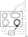
- FIG. 1 an exemplary embodiment of the system 2 according to the invention for performing the method according to the invention is shown as an example and roughly schematically.
- the system 2 has an inductively heated hob, that is to say an inductive hob 4, with a total of four hotplates 6.
- Each of the hotplates 6 is assigned a heating coil 8 for inductive heating of an installation device set up on the respective hotplate 6 in a manner known to those skilled in the art.
- the hob 4 has a hob control 10.
- the inductive hob 4 is in a switch-off mode A.
- the system 2 has a stand-up device 12 designed as a cooking pot.
- the installation device 12 comprises an induction coil 14 which can be inductively coupled to the heating coils 8 of the hob 4 and a transmission unit 16.
- the transmission unit 16 is designed as a Bluetooth transmitter.
- the installation device 12 comprises a sensor 17 for detecting an installation event and for detecting the nature of a base on which the installation device 12 has been installed. See the Fig. 2 . In a simpler embodiment, it is possible that the sensor is only designed to detect a set-up event.
- the sensor 17 is designed as an acceleration sensor, wherein vibrations can also be detected with the acceleration sensor.
- the sensor 17 is arranged in a first variant on a handle 19 of the installation device 12 and in a second variant on a vessel 21 of the installation device 12 for receiving a medium provided for preparation by means of the installation device 12.
- the two variants for positioning the sensor 17 on the installation device 12 are shown in FIG Fig. 2 denoted by the reference numerals 17 and 17 '.
- the installation device 12 has an operating element 23 designed as an operating button for manual operation by a user.
- the operating element 23 is provided in order to switch off the installation device 12. Furthermore, the functional scope of the sensor 17 overlaps at least partially with the functional scope of the operating element 23. This is explained in more detail below.
- the installation device 12 is designed and set up such that the transmitter unit 16 and the sensor 17 can be supplied with operating energy by means of the induction coil 14.
- the set-up device 12 also has a set-up device output unit 26 for outputting information to the user of the set-up device 12, depending on a set-up event detected by means of the sensor 17 and / or a base detected by means of the sensor 17 on which the set-up device 12 is set up has been, by means of the installation device output unit 26 information can be output to the user.
- the inductive hob can have a hob output unit for outputting information to the user of the installation device, depending on a positioning event detected by the sensor or a base detected by the sensor on which the installation device has been set up by means of the hob output unit information can be output to the user.
- the inductive hob 4 thus comprises at least one hotplate 6, at least one heating coil 8 assigned to the hotplate 6 and a hob control 10 for controlling the heating coil 8 in an operating mode E of the inductive hob 4 for heating a set-up device 12 set up on the hotplate 6 with a transmitter unit 16
- the hob control 10 is designed and set up in such a way that the inductive hob 4 can also be operated in a standby mode S, control of the respective heating coil 8 in the standby mode S not being possible.
- the hob control 10 is designed and set up in such a way that the inductive hob 4 can be operated in a standby mode B, the inductive hob 4 being able to be converted from the standby mode S to the standby mode B by means of a wake-up signal received by a receiving unit 18 of the hob control 10 .
- the respective heating coil 8 can be controlled in standby mode B by means of the hob control 10 in such a way that, on the one hand, effective heating of the installation device 12 for a preparation process is prevented and, on the other hand, a signal transmission between the transmitter unit 16 and the receiver unit 18 by means of the heating coil 8 is enabled.
- FIG Figs. 1 to 3 explained in more detail.
- the method according to the invention is shown as an example using a time-signal diagram.
- the method according to the invention basically works as follows: A user, not shown, of the system 2 places the installation device 12, which is designed as a cooking pot, on the plane in the image of FIG Fig. 1 Hotplate 6 of the hob 4 arranged at the bottom right.
- the inductive hob 4 is in its switch-off mode A, for example in which the inductive hob 4 has been completely switched off by means of a main switch (not shown)
- the user can use the inductive hob 4 of the system 2, for example by means of one from the prior art known operator intervention on the inductive hob 4, from the switch-off mode A directly to the operating mode E.
- the user can then carry out a preparation process, for example a cooking process, using the system 2 in a manner known to the person skilled in the art.
- the inductive hob 4 is in its standby mode S, that is to say in which the inductive hob 4 is not completely switched off, control of the heating coils 8 is not technically possible. To do this, the user would first have to transfer the inductive hob 4 to operating mode E, for example, in the manner explained above.
- the inductive hob 4 of the system 2 is designed and set up to be automatically transferred from the standby mode S to the standby mode B. This requires the above-mentioned wake-up signal, which is received by means of the receiving unit 18 of the hob control 10. This wake-up signal can be generated in different ways.
- the wake-up signal is triggered by actuating the operating element 23 arranged on the installation device 12 and in signal transmission connection with the transmitter unit 16 or by means of the sensor 17 arranged on the installation device 12 and in signal transmission connection with the transmitter unit 16 or by an actuation of an operating element arranged on the inductive hob 4 and in signal transmission connection with the receiving unit 18 of the hob control 10 or by actuation of an operating element arranged on a third device and in signal transmission connection with the receiving unit 18 of the hob control 10 is generated.
- the inductive hob 4 can be transferred from the standby mode S to the standby mode B in very different ways, which increases the ease of use of the system 2.
- the control element of the inductive hob 4 and the third-party device designed as a smartphone are not shown.
- the wake-up signal is generated by actuating the operating element 23 of the installation device 12, which is arranged on the installation device 12 and is in signal transmission connection with the transmitter unit 16.
- the user presses, for example, the operating element 23 of the set-up device 12, which is designed as a button, and places the set-up device 12 on the above-mentioned hotplate 6 of the inductive hob 4.
- This keystroke is evaluated by means of the transmission unit 16 of the installation device 12 and converted into the wake-up signal.
- the wake-up signal is then transmitted to the hob control 10 by means of the transmitter unit 16, the heating coil 8 and the receiver unit 18.
- the hob control 10 then transfers the inductive hob 4 from the standby mode S to the standby mode B.
- the transmitter unit 16 is powered by the voltage induced by the heating coil 8 into the induction coil 14 of the set-up device 12 placed on the hob 6 assigned to this heating coil 8 provided.
- the wake-up signal can be generated automatically by means of the sensor 17 arranged on the installation device 12 and in signal transmission connection with the transmitter unit 16.
- the sensor 17 it is automatically recognized by means of the sensor 17 that the installation device 12 has been set up by the user on the aforementioned hotplate 6 of the inductive hob 4.
- the sensor 17 has on the one hand detected the presence of a set-up event and on the other hand the surface on which the set-up device 12 has been set up. Manual actuation of the operating element 23 is therefore not necessary.
- the wake-up signal can also be generated by means of the operating element 23 in the manner explained above.
- the evaluation of output signals of the sensor 17 takes place in the present embodiment directly in the installation device 12.
- the transmitter unit 16 and the sensor 17 are induced by means of the voltage induced by the heating coil 8 in the induction coil 14 of the installation device 12 placed on the hotplate 6 assigned to this heating coil 8 supplied with operating energy.
- the electrical power with which the hob control 10 controls the heating coil 8 in standby mode B has an average value of less than or equal to 30 W, preferably less than or equal to 15 W. Furthermore, the electrical power with which the hob control 10 controls the heating coil 8 in standby mode B has a pause power ratio of greater than or equal to 1000: 1, namely an energization in a time interval of 160 ⁇ s compared to a pause interval of 2
- the hob control 10 starts the automatic assignment of the installation device 12 to the above-mentioned hob 6 of the inductive hob 4, which is explained in more detail below.
- a process routine for the automatic assignment of the installation device 12 to at least one of the hotplates 6 of the inductive hob 4 is started as a function of a set-up event detected by the sensor 17 and a base detected by the sensor 17 on which the set-up device 12 has been set up .
- the hob control 10 controls the heating coils 8 of the individual hotplates 6 one after the other, that is to say successively, with their respective performance profile. This is in the Fig.
- the line a the control of the to the in the image plane of Fig. 1
- the heating coil 8 corresponding to the hotplate 6 shown at the bottom left the line b the control of the to that in the image plane of Fig. 1
- the heating coil 8 corresponding to the hotplate 6 shown at the bottom right the line c the control of the to that in the plane of the drawing Fig. 1
- the heating coil 8 corresponding to the hotplate 6 shown at the top and the line d the control of the heating coil 8 in the plane of the drawing Fig. 1
- the hotplate 6 shown at the top left symbolizes the corresponding heating coil 8.
- the cooking area 6 shown at the bottom right is set up as a cooking pot 12, when the heating coil 8 assigned to this cooking area 6 is activated, a voltage is induced from this heating coil 8 in the induction coil 14 of the setting up device 12. See line b in Fig. 3 .
- the transmission unit 16 of the saucepan 12 which is designed as a Bluetooth transmitter, is supplied with the operating energy required for transmission.
- the induced voltage simultaneously triggers transmission of the transmission unit 16, namely the transmission of the response signal 20. See FIG Fig. 1 and 3 .
- the response signal 20 includes, on the one hand, an identification which identifies the installation device 12 as precisely this individual installation device 12.
- This identification of the installation device 12 can have cooking pot properties that are important for a cooking process on the inductive hob 4, for example.
- the response signal 20 comprises at least one of the means of the heating coil 8 in the image plane of FIG Fig. 1
- the cooking zone 6 shown at the bottom right in the induction coil 14 of the installation device 12 is a variable which correlates the power profile induced.
- this variable can be the performance profile as such. It is also conceivable, however, that this variable is at least one electrical and / or magnetic variable that characterizes the performance profile.
- the response signal 20 is sent to the receiving unit 18 of the hob control 10.
- the response signal 20 received by the receiving unit 18 is then transmitted in a manner known to the person skilled in the art to the evaluation unit 22 of the hob control 10 connected to the receiving unit 18 for evaluation.
- the response signal 20 is inter alia with the performance profile of the in the image plane of Fig. 1
- the hotplate 6 shown at the bottom right, on which the stand-up device 12 is set up, is compared with the associated heating coil 8 with which this heating coil 8 has been controlled by means of the hob control 10.
- the installation device 12 Since the at least one variable that correlates with this performance profile and has been transmitted with the response signal 20 from the installation device 12 to the hob control 10 corresponds to this performance profile, the installation device 12 becomes the one in the image plane of FIG Fig. 1
- the hob 6 shown at the bottom right is automatically assigned to the hob control 10 by means of the evaluation unit 22.
- the hob control 10 now knows that exactly this installation device 12 is set up on this hob 6 and on this basis can automatically transfer the inductive hob 4 from its standby mode B to its operating mode E and the cooking process, i.e. the preparation process, for this individual For example, control or regulate the installation device 12 by means of the control of the heating coil 8 assigned to this hotplate 6.
- the response signal 20 is in the evaluation unit 22 with the performance profiles of the other in the Fig. 1
- the heating coils 8 associated with the additional hotplates 6 shown are compared with which these heating coils 8 have been controlled by means of the hob control 10. However, since the installation device 12 is not set up on these hotplates 6 and thus not above the heating coils 8 assigned to these hotplates 6, the respective activation of these heating coils 8 does not lead to a response signal corresponding to one of these performance profiles.
- the hob control 10 automatically transfers the inductive hob 4 of the system 2 from the standby mode B to the operating mode E.
- the user can, for example, set the power for this heating coil 8 on the inductive hob 4 in a manner known to those skilled in the art.
- the hob control 10 transfers the inductive hob 4, For example, after a predetermined time span stored in the hob control 10 has elapsed, automatically from the standby mode B back to the standby mode S.
- An automatic assignment of the set-up device 12 to one of the hotplates 6 might not be possible, for example, because the set-up device 12 has been set up on a table on a trivet, not shown, made of wood.
- information is output to the user by means of the installation device output unit 26 as a function of the installation event detected by means of the sensor 17 and the base detected by the sensor 17 on which the installation device 12 has been installed .
- a warning signal is output as information if it has been detected by means of the sensor 17 that the base on which the set-up device 12 was set up is not one of the hotplates 6 of the inductive hob 4, but rather a base made of wood or fabric, for example the saucer mentioned above.
- Information to the user can also be provided in case take place when the installation of the installation device 12 on the inductive hob 4 has been detected by means of the sensor 17.
- control of the individual heating coils 8 of the inductive hob 4 is carried out with their respective performance profile in the standby mode B and in the operating mode E of the inductive hob 4, that is, continuously as a function of at least one predetermined time interval.
- the invention is not limited to the present embodiment.
- a filling quantity in the installation device and / or a state of the medium relevant to the preparation of the medium is / are detected as a function of output signals from the sensor.
- This further increases the functionality of the sensor.
- the filling quantity of the medium in the installation device it could also be detected whether the medium has reached its boiling point. It is also conceivable to record the boiling impression of the medium, that is to say the boiling behavior of the medium, in particular with regard to the density of the supplied heat output.
- the method according to the invention can be used to avoid noise emission during the preparation process.
- a working frequency of the heating coil as a function of Output signals of the sensor is adapted in such a way that a case of resonance in the individual installation device is avoided.
- the output signals of the sensor it is also possible for the output signals of the sensor to be evaluated at least partially in the hob control and / or in a third-party device that has a signal transmission connection with the hob control.
- An alternative to the exemplary embodiment of the automatic assignment of at least one installation device to at least one hob of the inductive hob provides, for example, that the hob control controls the heating coils with at least one assignment signal and a measuring unit of the installation device generates a vibration of the installation device that correlates with the assignment signal induced in the induction coil and the transmitting unit sends a response signal that identifies the set-up device and correlates with the detected vibration of the set-up device to the receiving unit of the hob control or a third-party device that is in signal transmission connection with the hob control and sends the response signal to an evaluation unit of the hob control or the third-party device with the Assignment signal of the at least one heating coil of this hotplate is compared and depending on this Verg the identified installation device is easily assigned to this hotplate.
- output signals from the sensor can be used in the process routine for automatic assignment of the installation device to at least one hotplate of the inductive hob.
- vibrations of the installation device detected by means of the sensor could be evaluated during the process routine in order to achieve the above-mentioned assignment. Accordingly, a measuring unit in addition to the sensor would not be absolutely necessary. See also the subsequently published German patent application DE 10 2018 119 969.4 of the applicant, the disclosure of which is fully incorporated into the present application.
Landscapes
- Physics & Mathematics (AREA)
- Electromagnetism (AREA)
- Induction Heating Cooking Devices (AREA)
- Electric Stoves And Ranges (AREA)
Abstract
Description
- Die Erfindung betrifft ein Aufstellgerät für ein induktives Kochfeld der im Oberbegriff des Patentanspruchs 1 genannten Art, ein System, umfassend ein induktives Kochfeld und ein Aufstellgerät, der im Oberbegriff des Patentanspruchs 7 genannten Art sowie ein Verfahren zum Betrieb des Systems der im Oberbegriff des Patentanspruchs 10 genannten Art.
- Derartige Aufstellgeräte, Systeme und Verfahren sind aus dem Stand der Technik in einer Vielzahl von voneinander verschiedenen Ausführungsformen bereits bekannt.
- Der Erfindung stellt sich somit das Problem, die Nutzung eines Systems, umfassend ein induktives Kochfeld und ein Aufstellgerät, zu verbessern.
- Erfindungsgemäß wird dieses Problem durch ein Aufstellgerät mit den Merkmalen des Patentanspruchs 1 gelöst, das dadurch gekennzeichnet ist, dass das Aufstellgerät mindestens einen Sensor zur Erkennung eines Aufstellereignisses oder zur Erkennung eines Aufstellereignisses und zur Erkennung der Beschaffenheit einer Unterlage, auf der das Aufstellgerät aufgestellt worden ist, aufweist. Ferner wird dieses Problem durch ein System mit den Merkmalen des Patentanspruchs 7 sowie ein Verfahren mit den Merkmalen des Patentanspruchs 10 gelöst. Vorteilhafte Ausgestaltungen und Weiterbildungen der Erfindung ergeben sich aus den nachfolgenden Unteransprüchen.
- Der mit der Erfindung erreichbare Vorteil besteht insbesondere darin, dass die Nutzung eines Systems, umfassend ein induktives Kochfeld und ein Aufstellgerät, verbessert ist. Beispielsweise ist der Bedienkomfort für einen Benutzer derartiger Systeme gesteigert. Aufgrund der automatischen Erkennung eines Aufstellereignisses oder eines Aufstellereignisses und der Beschaffenheit einer Unterlage, auf der das Aufstellgerät aufgestellt worden ist, ist es möglich, die Handhabung des erfindungsgemäßen Aufstellgeräts wie auch des erfindungsgemäßen Systems zu vereinfachen. Beispielsweise ist es damit möglich, einen Eingriff eines Benutzers automatisch zu erkennen und für die weitere Steuerung oder Regelung des Systems zu verwenden. Ferner können nachfolgende Schritte in der Zubereitung eines in dem Aufstellgerät befindlichen Mediums mittels des induktiven Kochfelds antizipiert werden, um so die weitere Zubereitung zu vereinfachen. Auch ist es mittels der Erfindung möglich, beispielsweise das induktive Kochfeld vor einer unsachgemäßen Handhabung zu schützen, so dass eine etwaige Beschädigung des induktiven Kochfelds sowie möglicherweise die Sicherheit gefährdende Situationen wirksam verhindert sind. Darüber hinaus ist es mittels der Erfindung möglich, den Energieverbrauch des Aufstellgeräts und des induktiven Kochfelds zu reduzieren, beispielsweise dadurch, dass lediglich dann eine Signalübertragung zwischen dem Aufstellgerät und der Kochfeldsteuerung des induktiven Kochfelds erfolgt, wenn ein Aufstellereignis oder ein Aufstellereignis und die Beschaffenheit einer Unterlage, auf der das Aufstellgerät aufgestellt worden ist, mittels des Sensors erkannt worden ist/sind. Der Begriff "Aufstellgerät" ist weit auszulegen und umfasst insbesondere alle denkbaren Arten von Kochgeschirr, beispielsweise Kochtöpfe oder Bratpfannen.
- Das Aufstellgerät ist nach Art, Funktionsweise, Form, Material und Dimensionierung in weiten geeigneten Grenzen frei wählbar. Dies gilt auch für den Sensor des Aufstellgeräts. Eine vorteilhafte Weiterbildung des erfindungsgemäßen Aufstellgeräts sieht vor, dass der Sensor als ein Schwingungssensor und/oder als ein Beschleunigungssensor ausgebildet ist. Auf diese Weise ist der Sensor auf einfache und gleichzeitig funktionssichere Art realisiert. Ferner ist es damit möglich, nachfolgende Schritte in der Zubereitung eines in dem Aufstellgerät befindlichen Mediums mittels des induktiven Kochfelds verbessert zu antizipieren, um so die weitere Zubereitung zusätzlich zu vereinfachen. Darüber hinaus ist mittels der Erfindung gemäß dieser Weiterbildung der Schutz des induktiven Kochfelds vor einer unsachgemäßen Handhabung weiter verbessert, so dass eine etwaige Beschädigung des induktiven Kochfelds sowie möglicherweise die Sicherheit gefährdende Situationen noch wirksamer verhindert sind.
- Zweckmäßigerweise ist es vorgesehen, dass der mindestens eine Sensor an einem Griff des Aufstellgeräts und/oder an einem Gefäß des Aufstellgeräts zur Aufnahme eines für die Zubereitung mittels des Aufstellgeräts vorgesehenen Mediums angeordnet ist. Eine Anordnung des Sensors an dem Griff des Aufstellgeräts hat beispielsweise den Vorteil, dass der Sensor in einem thermisch isolierten Bereich angeordnet ist. Eine Anordnung des Sensors an dem Gefäß des Aufstellgeräts hat wiederum den Vorteil, dass der Sensor näher zu dem Ort der Krafteinleitung bei dem Aufstellen des Aufstellgeräts auf die Unterlage, beispielsweise einer Kochstelle des induktiven Kochfelds, angeordnet ist.
- Eine weitere vorteilhafte Weiterbildung des erfindungsgemäßen Aufstellgeräts sieht vor, dass das Aufstellgerät zusätzlich ein Bedienelement zur manuellen Bedienung durch den Benutzer aufweist, wobei sich der Funktionsumfang des Sensors mit dem Funktionsumfang des Bedienelements zumindest teilweise überschneidet. Hierdurch ist eine Redundanz zu dem Sensor geschaffen. Ferner ist es beispielsweise denkbar, dass das Bedienelement zum Ausschalten des Aufstellgeräts dient.
- Eine andere vorteilhafte Weiterbildung des erfindungsgemäßen Aufstellgeräts sieht vor, dass das Aufstellgerät derart ausgebildet und eingerichtet ist, dass die Sendeeinheit und/oder die Messeinheit und/oder der Sensor mittels der Induktionsspule mit einer Betriebsenergie versorgbar ist/sind. Auf diese Weise ist es möglich, dass lediglich ein kleiner und damit platzsparender Energiespeicher zur Speicherung der Betriebsenergie für das Aufstellgerät ausreichend ist.
- Entsprechend sieht eine vorteilhafte Weiterbildung des erfindungsgemäßen Systems vor, dass die Sendeeinheit und/oder die Messeinheit und/oder der Sensor bei einer mittels der Heizspule in die Induktionsspule des auf der dieser Heizspule zugeordneten Kochstelle aufgestellten Aufstellgeräts induzierten Spannung mit einer Betriebsenergie versorgbar ist/sind.
- Ferner sieht eine vorteilhafte Weiterbildung des erfindungsgemäßen Aufstellgeräts vor, dass das Aufstellgerät eine Aufstellgerät-Ausgabeeinheit zur Ausgabe von Informationen an den Benutzer des Aufstellgeräts aufweist, wobei in Abhängigkeit von einem mittels des Sensors erkannten Aufstellereignisses oder einer mittels des Sensors erkannten Unterlage, auf der das Aufstellgerät aufgestellt worden ist, mittels der Aufstellgerät-Ausgabeeinheit eine Information an den Benutzer ausgebbar ist. Hierdurch ist eine Rückmeldung, beispielsweise über das Vorliegen eines Aufstellereignisses oder die Beschaffenheit der Unterlage, an den Benutzer des Aufstellgeräts ermöglicht. Beispielsweise ist es denkbar, dass bei einem noch Restwärme aufweisenden Aufstellgerät als Information ein Warnsignal ausgegeben wird, wenn mittels des Sensors erkannt worden ist, dass es sich bei der Unterlage, auf der das Aufstellgerät aufgestellt worden ist, nicht um eine Kochstelle des induktiven Kochfelds, sondern um eine Unterlage aus Holz oder Stoff handelt.
- Entsprechend sieht eine weitere vorteilhafte Weiterbildung des erfindungsgemäßen Systems vor, dass das induktive Kochfeld eine Kochfeld-Ausgabeeinheit zur Ausgabe von Informationen an den Benutzer des Aufstellgeräts aufweist, wobei in Abhängigkeit von einem mittels des Sensors erkannten Aufstellereignisses oder einer mittels des Sensors erkannten Unterlage, auf der das Aufstellgerät aufgestellt worden ist, mittels der Kochfeld-Ausgabeeinheit eine Information an den Benutzer ausgebbar ist.
- Entsprechend sieht auch eine vorteilhafte Weiterbildung des erfindungsgemäßen Verfahrens vor, dass in Abhängigkeit von einem mittels des Sensors erkannten Aufstellereignisses oder einer mittels des Sensors erkannten Unterlage, auf der das Aufstellgerät aufgestellt worden ist, mittels der Aufstellgerät-Ausgabeeinheit und/oder mittels der Kochfeld-Ausgabeeinheit eine Information an den Benutzer ausgegeben wird.
- Grundsätzlich ist es denkbar, dass die Ansteuerung der Heizspule in Abhängigkeit von einem mittels des Sensors erkannten Aufstellereignisses oder einer mittels des Sensors erkannten Unterlage, auf der das Aufstellgerät aufgestellt worden ist, dahingehend erfolgt, dass die Heizspule beispielsweise direkt mit einer für einen Zubereitungsvorgang ausreichenden elektrischen Leistung bestromt wird. Ferner ist es denkbar, dass bei einer Erkennung der Aufstellung des Aufstellgeräts auf eine Kochstelle des induktiven Kochfelds und eines übermäßigen Schwenkens des Aufstellgeräts mittels des Sensors die Zufuhr von elektrischer Leistung automatisch reduziert wird, um beispielsweise Bauteile eines Schwingkreises des induktiven Kochfelds vor einer Beschädigung zu schützen.
- Eine vorteilhafte Weiterbildung des erfindungsgemäßen Verfahrens sieht vor, dass in Abhängigkeit von einem mittels des Sensors erkannten Aufstellereignisses oder einer mittels des Sensors erkannten Unterlage, auf der das Aufstellgerät aufgestellt worden ist, eine Verfahrensroutine zur automatischen Zuordnung des Aufstellgeräts zu mindestens einer Kochstelle des induktiven Kochfelds gestartet wird. Auf diese Weise ist es beispielsweise möglich, die Heizspule zunächst mit einer reduzierten elektrischen Leistung anzusteuern, die zwar ausreichend ist, um eine automatische Zuordnung des Aufstellgeräts zu mindestens einer Kochstelle des induktiven Kochfelds vorzunehmen, jedoch keine für einen Zubereitungsvorgang wirksame Aufheizung des Aufstellgeräts bewirkt. Beispielsweise ist dies mittels eines geeigneten Pausen-Leistungs-Verhältnisses realisierbar. Die Heizspule wird erst dann mit der für einen Zubereitungsvorgang ausreichenden elektrischen Leistung bestromt, wenn die Verfahrensroutine eine automatische Zuordnung des Aufstellgeräts zu der Kochstelle, die zu der vorgenannten Heizspule korrespondiert, ergibt. Entsprechend ist die Sicherheit weiter verbessert.
- Die Verfahrensroutine zur automatischen Zuordnung des Aufstellgeräts zu mindestens einer Kochstelle des induktiven Kochfelds ist in weiten geeigneten Grenzen frei wählbar. Eine vorteilhafte Weiterbildung der vorgenannten Ausführungsform des erfindungsgemäßen Verfahrens sieht vor, dass in der Verfahrensroutine zur automatischen Zuordnung des Aufstellgeräts zu mindestens einer Kochstelle des induktiven Kochfelds Ausgangssignale des Sensors verwendet werden. Beispielsweise könnten mittels des Sensors detektierte Vibrationen des Aufstellgeräts während der Verfahrensroutine ausgewertet werden, um so die oben genannte Zuordnung zu erzielen.
- Für die automatische Zuordnung mindestens eines Aufstellgeräts zu mindestens einer Kochstelle des induktiven Kochfelds sind grundsätzlich eine Vielzahl von voneinander verschiedenen Verfahren denkbar.
- Beispielsweise sei hier auf die
DE 10 2017 112 945 B3 sowie auf die nachveröffentlichten deutschen PatentanmeldungenDE 10 2018 119 953.8 ,DE 10 2018 119 965.1 undDE 10 2018 119 969.4 der Anmelderin verwiesen, deren Offenbarungsgehalt jeweils vollumfänglich in die vorliegende Anmeldung inkorporiert ist. - Eine weitere vorteilhafte Weiterbildung des erfindungsgemäßen Verfahrens sieht vor, dass in Abhängigkeit von Ausgangssignalen des Sensors eine Füllmenge in dem Aufstellgerät und/oder ein für die Zubereitung des Mediums relevanter Zustand des Mediums detektiert wird/werden. Hierdurch ist die Funktionalität des Sensors weiter gesteigert. Beispielsweise könnte alternativ oder zusätzlich zu der Füllmenge des Mediums in dem Aufstellgerät auch detektiert werden, ob das Medium seinen Siedepunkt erreicht hat. Auch ist eine Erfassung des Siedeeindrucks des Mediums, also des Siedeverhaltens des Mediums, insbesondere in Bezug auf die zugeführte Wärmeleistung, denkbar.
- Ferner kann das erfindungsgemäße Verfahren dazu verwendet werden, um eine Geräuschemission bei dem Zubereitungsvorgang zu vermeiden. Beispielsweise, in dem eine Arbeitsfrequenz der Heizspule in Abhängigkeit von Ausgangssignalen des Sensors dahingehend angepasst wird, dass ein Resonanzfall bei dem individuellen Aufstellgerät vermieden wird.
- Eine andere vorteilhafte Weiterbildung des erfindungsgemäßen Verfahrens sieht vor, dass die Auswertung von Ausgangssignalen des Sensors in dem Aufstellgerät erfolgt. Auf diese Weise ist es nicht erforderlich, dass die Ausgangssignale des Sensors kontinuierlich oder zumindest in regelmäßigen Zeitabständen von dem Aufstellgerät zu der Kochfeldsteuerung oder einem Drittgerät übertragen werden müssen. Jedoch ist es auch möglich, dass die Auswertung der Ausgangssignale des Sensors zumindest teilweise in der Kochfeldsteuerung und/oder in einem mit der Kochfeldsteuerung in Signalübertragungsverbindung stehenden Drittgerät erfolgt.
- Ein Ausführungsbeispiel der Erfindung ist in den Zeichnungen rein schematisch dargestellt und wird nachfolgend näher beschrieben. Es zeigt
- Figur 1
- ein Ausführungsbeispiel des erfindungsgemäßen Systems,
- Figur 2
- ein Ausführungsbeispiel des erfindungsgemäßen Aufstellgeräts und
- Figur 3
- ein Ausführungsbeispiel des erfindungsgemäßen Verfahrens.
- In der
Fig. 1 ist ein Ausführungsbeispiel des erfindungsgemäßen Systems 2 zur Durchführung des erfindungsgemäßen Verfahrens exemplarisch und grob schematisch dargestellt. Das System 2 weist ein induktiv beheiztes Kochfeld, also ein induktives Kochfeld 4, mit insgesamt vier Kochstellen 6 auf. Jeder der Kochstellen 6 ist eine Heizspule 8 zur induktiven Beheizung eines auf der jeweiligen Kochstelle 6 aufgestellten Aufstellgeräts auf dem Fachmann bekannte Weise zugeordnet. Zur Ansteuerung der einzelnen Heizspulen 8 weist das Kochfeld 4 eine Kochfeldsteuerung 10 auf. In einem vollständig ausgeschalteten Zustand befindet sich das induktive Kochfeld 4 in einem Ausschaltmodus A. Ferner weist das System 2 ein als Kochtopf ausgebildetes Aufstellgerät 12 auf. Das Aufstellgerät 12 umfasst eine mit den Heizspulen 8 des Kochfelds 4 induktiv koppelbare Induktionsspule 14 und eine Sendeeinheit 16. Die Sendeeinheit 16 ist bei dem vorliegenden Ausführungsbeispiel als ein Bluetooth-Sender ausgebildet. Ferner umfasst das Aufstellgerät 12 einen Sensor 17 zur Erkennung eines Aufstellereignisses und zur Erkennung der Beschaffenheit einer Unterlage, auf der das Aufstellgerät 12 aufgestellt worden ist. Siehe dieFig. 2 . In einer einfacheren Ausführungsform ist es möglich, dass der Sensor lediglich zur Erkennung eines Aufstellereignisses ausgebildet ist. - Der Sensor 17 ist als ein Beschleunigungssensor ausgebildet, wobei mit dem Beschleunigungssensor auch Schwingungen detektierbar sind. Der Sensor 17 ist in einer ersten Variante an einem Griff 19 des Aufstellgeräts 12 und in einer zweiten Variante an einem Gefäß 21 des Aufstellgeräts 12 zur Aufnahme eines für die Zubereitung mittels des Aufstellgeräts 12 vorgesehenen Mediums angeordnet. Die beiden Varianten für die Positionierung des Sensors 17 an dem Aufstellgerät 12 sind in der
Fig. 2 mit den Bezugszeichen 17 und 17' bezeichnet. Nachfolgend wird der Einfachheit halber lediglich das Bezugszeichen 17 verwendet; jedoch sind stets beide vorgenannten Varianten der Positionierung des Sensors 17, 17' gemeint. Zusätzlich weist das Aufstellgerät 12 ein als Bedientaste ausgebildetes Bedienelement 23 zur manuellen Bedienung durch einen Benutzer auf. Das Bedienelement 23 ist bei dem vorliegenden Ausführungsbeispiel dazu vorgesehen, um das Aufstellgerät 12 auszuschalten. Ferner überschneidet sich der Funktionsumfang des Sensors 17 mit dem Funktionsumfang des Bedienelements 23 zumindest teilweise. Dies wird nachfolgend noch näher erläutert. Das Aufstellgerät 12 ist derart ausgebildet und eingerichtet, dass die Sendeeinheit 16 und der Sensor 17 mittels der Induktionsspule 14 mit einer Betriebsenergie versorgbar sind. - Auch weist das Aufstellgerät 12 eine Aufstellgerät-Ausgabeeinheit 26 zur Ausgabe von Informationen an den Benutzer des Aufstellgeräts 12 auf, wobei in Abhängigkeit von einem mittels des Sensors 17 erkannten Aufstellereignisses und/oder einer mittels des Sensors 17 erkannten Unterlage, auf der das Aufstellgerät 12 aufgestellt worden ist, mittels der Aufstellgerät-Ausgabeeinheit 26 eine Information an den Benutzer ausgebbar ist.
- Alternativ oder zusätzlich dazu kann das induktive Kochfeld in einer anderen Ausführungsform des erfindungsgemäßen Systems eine Kochfeld-Ausgabeeinheit zur Ausgabe von Informationen an den Benutzer des Aufstellgeräts aufweisen, wobei in Abhängigkeit von einem mittels des Sensors erkannten Aufstellereignisses oder einer mittels des Sensors erkannten Unterlage, auf der das Aufstellgerät aufgestellt worden ist, mittels der Kochfeld-Ausgabeeinheit eine Information an den Benutzer ausgebbar ist.
- Das induktive Kochfeld 4 umfasst somit mindestens eine Kochstelle 6, mindestens eine der Kochstelle 6 zugeordnete Heizspule 8 und eine Kochfeldsteuerung 10 zur Ansteuerung der Heizspule 8 in einem Betriebsmodus E des induktiven Kochfelds 4 zur Beheizung eines auf der Kochstelle 6 aufgestellten Aufstellgeräts 12 mit einer Sendeeinheit 16. Die Kochfeldsteuerung 10 ist derart ausgebildet und eingerichtet, dass das induktive Kochfeld 4 zusätzlich in einem Standby-Modus S betreibbar ist, wobei eine Ansteuerung der jeweiligen Heizspule 8 in dem Standby-Modus S nicht ermöglicht ist. Ferner ist die Kochfeldsteuerung 10 derart ausgebildet und eingerichtet, dass das induktive Kochfeld 4 in einem Bereitschaftsmodus B betreibbar ist, wobei das induktive Kochfeld 4 mittels eines von einer Empfangseinheit 18 der Kochfeldsteuerung 10 empfangenen Wecksignals von dem Standby-Modus S in den Bereitschaftsmodus B überführbar ist. Die jeweilige Heizspule 8 ist in dem Bereitschaftsmodus B mittels der Kochfeldsteuerung 10 derart ansteuerbar, dass zum einen eine für einen Zubereitungsvorgang wirksame Beheizung des Aufstellgeräts 12 verhindert ist und zum anderen eine Signalübertragung zwischen der Sendeeinheit 16 und der Empfangseinheit 18 mittels der Heizspule 8 ermöglicht ist.
- Im Nachfolgenden wird das erfindungsgemäße Verfahren gemäß dem vorliegenden Ausführungsbeispiel des Systems 2 anhand der
Fig. 1 bis 3 näher erläutert. In derFig. 3 ist das erfindungsgemäße Verfahren anhand eines Zeit-Signal-Diagramms exemplarisch dargestellt. - Das erfindungsgemäße Verfahren funktioniert grundsätzlich wie folgt:
Ein nicht dargestellter Benutzer des Systems 2 stellt das als Kochtopf ausgebildete Aufstellgerät 12 auf die in der Bildebene vonFig. 1 rechts unten angeordnete Kochstelle 6 des Kochfelds 4. - Sofern sich das induktive Kochfeld 4 in dessen Ausschaltmodus A befindet, beispielsweise in dem das induktive Kochfeld 4 mittels eines nicht dargestellten Hauptschalters vollständig ausgeschaltet worden ist, kann der nicht dargestellte Benutzer das induktive Kochfeld 4 des Systems 2, beispielsweise mittels eines aus dem Stand der Technik bekannten Bedieneingriffs an dem induktiven Kochfeld 4, von dem Ausschaltmodus A direkt in den Betriebsmodus E überführen. Der Benutzer kann dann auf dem Fachmann bekannte Weise einen Zubereitungsvorgang, beispielsweise einen Kochvorgang, mittels des Systems 2 durchführen.
- Befindet sich das induktive Kochfeld 4 in dessen Standby-Modus S, also in dem das induktive Kochfeld 4 nicht vollständig ausgeschaltet ist, ist eine Ansteuerung der Heizspulen 8 technisch nicht ermöglicht. Dazu müsste der Benutzer das induktive Kochfeld 4 beispielsweise erst auf die oben erläuterte Weise in den Betriebsmodus E überführen.
- Jedoch ist das induktive Kochfeld 4 des Systems 2 dazu ausgebildet und eingerichtet, um von dem Standby-Modus S automatisch in den Bereitschaftsmodus B überführt zu werden. Hierfür bedarf es des oben genannten Wecksignals, das mittels der Empfangseinheit 18 der Kochfeldsteuerung 10 empfangen wird. Dieses Wecksignal kann auf voneinander verschiedene Weise erzeugt werden. Bei dem vorliegenden Ausführungsbeispiel ist es vorgesehen, dass das Wecksignal mittels einer Betätigung des an dem Aufstellgerät 12 angeordneten und mit der Sendeeinheit 16 in Signalübertragungsverbindung stehenden Bedienelements 23 oder mittels des an dem Aufstellgerät 12 angeordneten und mit der Sendeeinheit 16 in Signalübertragungsverbindung stehenden Sensors 17 oder mittels einer Betätigung eines an dem induktiven Kochfeld 4 angeordneten und mit der Empfangseinheit 18 der Kochfeldsteuerung 10 in Signalübertragungsverbindung stehenden Bedienelements oder mittels einer Betätigung eines an einem Drittgerät angeordneten und mit der Empfangseinheit 18 der Kochfeldsteuerung 10 in Signalübertragungsverbindung stehenden Bedienelements erzeugt wird. Entsprechend ist das induktive Kochfeld 4 auf sehr unterschiedliche Weise von dem Standby-Modus S in den Bereitschaftsmodus B überführbar, was den Bedienkomfort des Systems 2 steigert. Das Bedienelement des induktiven Kochfelds 4 und das als Smartphone ausgebildete Drittgerät sind nicht dargestellt.
- Beispielsweise wird das Wecksignal mittels einer Betätigung des an dem Aufstellgerät 12 angeordneten und mit der Sendeeinheit 16 in Signalübertragungsverbindung stehenden Bedienelements 23 des Aufstellgeräts 12 generiert. Hierfür drückt der Benutzer beispielsweise das als Taste ausgebildete Bedienelement 23 des Aufstellgeräts 12 und stellt das Aufstellgerät 12 auf die oben genannte Kochstelle 6 des induktiven Kochfelds 4 auf. Dieser Tastendruck wird mittels der Sendeeinheit 16 des Aufstellgeräts 12 ausgewertet und in das Wecksignal umgewandelt. Das Wecksignal wird dann mittels der Sendeinheit 16, der Heizspule 8 und der Empfangseinheit 18 in die Kochfeldsteuerung 10 übertragen. Die Kochfeldsteuerung 10 überführt das induktive Kochfeld 4 daraufhin von dem Standby-Modus S in den Bereitschaftsmodus B. Die Sendeeinheit 16 wird mittels der durch die Heizspule 8 in die Induktionsspule 14 des auf der dieser Heizspule 8 zugeordneten Kochstelle 6 aufgestellten Aufstellgeräts 12 induzierten Spannung mit Betriebsenergie versorgt.
- Zusätzlich dazu ist es vorgesehen, dass das Wecksignal mittels des an dem Aufstellgerät 12 angeordneten und mit der Sendeeinheit 16 in Signalübertragungsverbindung stehenden Sensors 17 automatisch erzeugbar ist. Beispielsweise wird mittels des Sensors 17 automatisch erkannt, dass das Aufstellgerät 12 von dem Benutzer auf die vorgenannte Kochstelle 6 des induktiven Kochfelds 4 aufgestellt worden ist. Der Sensor 17 hat also zum einen das Vorliegen eines Aufstellereignisses und zum anderen die Unterlage, auf der das Aufstellgerät 12 aufgestellt worden ist, detektiert. Somit ist eine manuelle Betätigung des Bedienelements 23 nicht erforderlich. Jedoch ist es beispielsweise aus Gründen der Redundanz vorteilhaft, dass das Wecksignal auf die oben erläuterte Weise auch mittels des Bedienelements 23 generiert werden kann. Die Auswertung von Ausgangssignalen des Sensors 17 erfolgt bei dem vorliegenden Ausführungsbeispiel direkt in dem Aufstellgerät 12. Die Sendeeinheit 16 und der Sensor 17 werden mittels der durch die Heizspule 8 in die Induktionsspule 14 des auf der dieser Heizspule 8 zugeordneten Kochstelle 6 aufgestellten Aufstellgeräts 12 induzierten Spannung mit Betriebsenergie versorgt.
- Die elektrische Leistung, mit der die Kochfeldsteuerung 10 die Heizspule 8 in dem Bereitschaftsmodus B ansteuert, weist einen Mittelwert von kleiner oder gleich 30 W, bevorzugt kleiner oder gleich 15 W, auf. Ferner weist die elektrische Leistung, mit der die Kochfeldsteuerung 10 die Heizspule 8 in dem Bereitschaftsmodus B ansteuert ein Pausen-Leistungs-Verhältnis von größer oder gleich 1000:1 auf, nämlich eine Bestromung in einem Zeitintervall von 160 µs im Vergleich zu einem Pausenintervall von 2 s. Hierdurch ist zum einen eine für einen Zubereitungsvorgang wirksame Beheizung des Aufstellgeräts 12 verhindert und zum anderen eine Signalübertragung zwischen der Sendeeinheit 16 und der Empfangseinheit 18 mittels der Heizspule 8 ermöglicht. Ferner ist eine Übertragung einer Betriebsenergie von dem induktiven Kochfeld 4 zu dem Aufstellgerät 12, das auf der dieser Heizspule 8 zugeordneten Kochstelle 6 aufgestellt ist, mittels der Heizspule 8 ermöglicht.
- Mit der Überführung des induktiven Kochfelds 4 von dessen Standby-Modus S in dessen Bereitschaftsmodus B wird mittels der Kochfeldsteuerung 10 die automatische Zuordnung des Aufstellgeräts 12 zu der oben genannten Kochstelle 6 des induktiven Kochfelds 4 gestartet, die nachfolgend näher erläutert ist. Es wird also in Abhängigkeit von einem mittels des Sensors 17 erkannten Aufstellereignisses und einer mittels des Sensors 17 erkannten Unterlage, auf der das Aufstellgerät 12 aufgestellt worden ist, eine Verfahrensroutine zur automatischen Zuordnung des Aufstellgeräts 12 zu mindestens einer der Kochstellen 6 des induktiven Kochfelds 4 gestartet.
- Wie oben beschrieben hat der Benutzer des Systems 2 das Kochfeld 4 eingeschaltet und das als Kochtopf ausgebildete Aufstellgerät 12 auf der in der Bildebene von
Fig. 1 rechts unten, also rechts vorne, angeordneten Kochstelle 6 des Kochfelds 4 aufgestellt. Nach der Überführung des Kochfelds 4 von dessen Standby-Modus S in dessen Bereitschaftsmodus B zu einem Zeitpunkt t= 0 s, das in derFig. 3 durch einen Pfeil 24 symbolisiert ist, steuert die Kochfeldsteuerung 10 die Heizspulen 8 der einzelnen Kochstellen 6 nacheinander, also sukzessive, mit deren jeweiligem Leistungsprofil an. Dies ist in derFig. 3 mittels der Linien a, b, c und d symbolisiert, wobei die Linie a die Ansteuerung der zu der in der Bildebene vonFig. 1 links unten dargestellten Kochstelle 6 korrespondierenden Heizspule 8, die Linie b die Ansteuerung der zu der in der Bildebene vonFig. 1 rechts unten dargestellten Kochstelle 6 korrespondierenden Heizspule 8, die Linie c die Ansteuerung der zu der in der Bildebene vonFig. 1 recht oben dargestellten Kochstelle 6 korrespondierenden Heizspule 8 und die Linie d die Ansteuerung der zu der in der Bildebene vonFig. 1 links oben dargestellten Kochstelle 6 korrespondierenden Heizspule 8 symbolisiert. - Da auf der in der Bildebene von
Fig. 1 rechts unten dargestellten Kochstelle 6 das als Kochtopf ausgebildete Aufstellgerät 12 aufgestellt ist, wird bei der Ansteuerung der dieser Kochstelle 6 zugeordneten Heizspule 8 eine Spannung von dieser Heizspule 8 in der Induktionsspule 14 des Aufstellgeräts 12 induziert. Siehe hierzu die Linie b inFig. 3 . Aufgrund der in der Induktionsspule 14 induzierten Spannung wird die als Bluetooth-Sender ausgebildete Sendeeinheit 16 des Kochtopfs 12 mit der für ein Senden erforderlichen Betriebsenergie versorgt. Darüber hinaus wird mittels der induzierten Spannung gleichzeitig ein Senden der Sendeeinheit 16 ausgelöst, nämlich das Senden des Antwortsignals 20. SieheFig. 1 und3 . Das Antwortsignal 20 umfasst zum einen eine das Aufstellgerät 12 als genau dieses individuelle Aufstellgerät 12 kennzeichnende Identifizierung. Diese Identifizierung des Aufstellgeräts 12 kann beispielsweise für einen Garvorgang auf dem induktiven Kochfeld 4 wichtige Kochtopfeigenschaften aufweisen. Zum anderen umfasst das Antwortsignal 20 mindestens eine zu dem mittels der Heizspule 8 der in der Bildebene vonFig. 1 rechts unten dargestellten Kochstelle 6 in die Induktionsspule 14 des Aufstellgeräts 12 induzierten Leistungsprofil korrelierende Größe. Beispielsweise kann es sich bei dieser Größe um das Leistungsprofil als solches handeln. Denkbar ist jedoch auch, dass diese Größe mindestens eine das Leistungsprofil charakterisierende elektrische und/oder magnetische Größe ist. - Das Antwortsignal 20 wird an die Empfangseinheit 18 der Kochfeldsteuerung 10 gesendet. Das von der Empfangseinheit 18 empfangene Antwortsignal 20 wird dann auf dem Fachmann bekannte Weise an die mit der Empfangseinheit 18 signalübertragend verbundene Auswerteeinheit 22 der Kochfeldsteuerung 10 zur Auswertung übertragen. In der Auswerteeinheit 22 wird das Antwortsignal 20 unter anderem mit dem Leistungsprofil der der in der Bildebene von
Fig. 1 rechts unten dargestellten Kochstelle 6, auf der das als Kochtopf ausgebildete Aufstellgerät 12 aufgestellt ist, zugeordneten Heizspule 8 verglichen, mit dem diese Heizspule 8 mittels der Kochfeldsteuerung 10 angesteuert worden ist. Da die zu diesem Leistungsprofil korrelierende mindestens eine Größe, die mit dem Antwortsignal 20 von dem Aufstellgerät 12 an die Kochfeldsteuerung 10 übertragen worden ist, mit diesem Leistungsprofil übereinstimmt, wird das Aufstellgerät 12 der in der Bildebene vonFig. 1 rechts unten dargestellten Kochstelle 6 mittels der Auswerteeinheit 22 der Kochfeldsteuerung 10 automatisch zugeordnet. Die Kochfeldsteuerung 10 weiß nun, dass auf dieser Kochstelle 6 genau dieses Aufstellgerät 12 aufgestellt ist und kann auf dieser Basis das induktive Kochfeld 4 automatisch von dessen Bereitschaftsmodus B in dessen Betriebsmodus E überführen und den Garvorgang, also den Zubereitungsvorgang, für dieses individuelle Aufstellgerät 12 mittels der Ansteuerung der dieser Kochstelle 6 zugeordneten Heizspule 8 beispielsweise steuern oder regeln. Das Antwortsignal 20 wird in der Auswerteeinheit 22 auch mit den Leistungsprofilen der übrigen den in derFig. 1 dargestellten weiteren Kochstellen 6 zugeordneten Heizspulen 8 verglichen, mit denen diese Heizspulen 8 mittels der Kochfeldsteuerung 10 angesteuert worden sind. Da das Aufstellgerät 12 jedoch nicht auf diese Kochstellen 6 und damit nicht über den diesen Kochstellen 6 zugeordneten Heizspulen 8 aufgestellt ist, führt die jeweilige Ansteuerung dieser Heizspulen 8 nicht zu einem zu einem dieser Leistungsprofile korrespondierenden Antwortsignal. - Wie aus
Fig. 3 weiter ersichtlich ist, erfolgen auf die in der Zeitachse links dargestellten Ansteuerungen der übrigen Heizspulen 8 des induktiven Kochfelds 4 keine Antwortsignale von etwaigen anderen Aufstellgeräten. - Gemäß den vorgenannten Ausführungen war die Zuordnung des Aufstellgeräts 12 zu der in der Bildebene von
Fig. 1 rechts unten dargestellten Kochstelle 6 und damit zu der zu dieser Kochstelle 6 korrespondierenden Heizspule 8 erfolgreich, so dass die Kochfeldsteuerung 10 das induktive Kochfeld 4 des Systems 2 automatisch von dem Bereitschaftsmodus B in den Betriebsmodus E überführt. Der Benutzer kann beispielsweise an dem induktiven Kochfeld 4 auf dem Fachmann bekannte Weise eine Leistungseinstellung für diese Heizspule 8 vornehmen. - Sofern eine automatische Zuordnung des Aufstellgeräts 12 zu einer der Kochstellen 6 des induktiven Kochfelds 4 des Systems 2 nicht erfolgt, beispielsweise, weil das Aufstellgerät 12 auf keiner der Kochstellen 6 des induktiven Kochfelds 4 aufgestellt worden ist, überführt die Kochfeldsteuerung 10 das induktive Kochfeld 4, beispielsweise nach Ablauf einer vorher festgelegten und in der Kochfeldsteuerung 10 abgespeicherten Zeitspanne, automatisch von dem Bereitschaftsmodus B zurück in den Standby-Modus S.
- Eine automatische Zuordnung des Aufstellgeräts 12 zu einer der Kochstellen 6 könnte beispielsweise deshalb nicht möglich sein, weil das Aufstellgerät 12 beispielsweise auf einem nicht dargestelltenTopfuntersetzer aus Holz auf einem Tisch aufgestellt worden ist. In diesem Fall kann es vorgesehen sein, dass in Abhängigkeit von dem mittels des Sensors 17 erkannten Aufstellereignis und der mittels des Sensors 17 erkannten Unterlage, auf der das Aufstellgerät 12 aufgestellt worden ist, mittels der Aufstellgerät-Ausgabeeinheit 26 eine Information an den Benutzer ausgegeben wird. Beispielsweise ist es denkbar, dass bei einem noch Restwärme aufweisenden Aufstellgerät 12 als Information ein Warnsignal ausgegeben wird, wenn mittels des Sensors 17 erkannt worden ist, dass es sich bei der Unterlage, auf der das Aufstellgerät 12 aufgestellt worden ist, nicht um eine der Kochstellen 6 des induktiven Kochfelds 4, sondern um eine Unterlage aus Holz oder Stoff, beispielsweise den oben genannten Topfuntersetzer, handelt. Eine Information an den Benutzer kann auch für den Fall erfolgen, wenn mittels des Sensors 17 das Aufstellen des Aufstellgeräts 12 auf das induktive Kochfeld 4 erkannt worden ist.
- Analog zu der oben erläuterten Überführung des induktiven Kochfelds 4 von dessen Ausschaltmodus A in dessen Betriebsmodus E ist es bei dem vorliegenden Ausführungsbeispiel auch möglich, das induktive Kochfeld 4 von dem Standby-Modus S direkt in den Betriebsmodus E zu überführen.
- Bei dem vorliegenden Ausführungsbeispiel werden die einzelnen Heizspulen 8 des Kochfelds 4 in dem Bereitschaftsmodus B und in dem Betriebsmodus E des induktiven Kochfelds 4 in vorher festgelegten Zeitabständen unabhängig von einem Wecksignal kontinuierlich sukzessive angesteuert. Bei jedem Durchlauf der Ansteuerung der einzelnen Heizspulen 8 mittels der Kochfeldsteuerung 10 werden immer alle vier Heizspulen 8 des Kochfelds 4 sukzessive angesteuert. Nach dem in der
Fig. 3 links dargestellten Durchlauf beginnt ab t= 3,5 s ein erneuter Durchlauf mit der sukzessiven Ansteuerung der Heizspulen 8 des induktiven Kochfelds 4. Bei dem vorliegenden Ausführungsbeispiel erfolgt die Ansteuerung der einzelnen Heizspulen 8 des induktiven Kochfeldes 4 mit deren jeweiligem Leistungsprofil in dem Bereitschaftsmodus B und in dem Betriebsmodus E des induktiven Kochfelds 4 also in Abhängigkeit mindestens eines vorher festgelegten Zeitintervalls kontinuierlich. - Die automatische Überführung des induktiven Kochfelds 4 von dessen Bereitschaftsmodus B in dessen Betriebsmodus E erfolgt zum einen durch den oben bereits erläuterten Bedieneingriff und damit analog zu der Überführung von dem Ausschaltmodus A in den Betriebsmodus E. Zum anderen erfolgt die Überführung von dem Bereitschaftsmodus B in den Betriebsmodus E automatisch durch eine erfolgreiche Zuordnung von dem Aufstellgerät 12 auf der einen Seite zu einer der Kochstellen 6 des induktiven Kochfelds 4 auf der anderen Seite.
- Die Erfindung ist nicht auf das vorliegende Ausführungsbeispiel begrenzt. Beispielsweise kann es vorgesehen sein, dass in Abhängigkeit von Ausgangssignalen des Sensors eine Füllmenge in dem Aufstellgerät und/oder ein für die Zubereitung des Mediums relevanter Zustand des Mediums detektiert wird/werden. Hierdurch ist die Funktionalität des Sensors weiter gesteigert. Beispielsweise könnte alternativ oder zusätzlich zu der Füllmenge des Mediums in dem Aufstellgerät auch detektiert werden, ob das Medium seinen Siedepunkt erreicht hat. Auch ist eine Erfassung des Siedeeindrucks des Mediums, also des Siedeverhaltens des Mediums, insbesondere in Bezug auf die Dichte der zugeführten Wärmeleistung, denkbar. Ferner kann das erfindungsgemäße Verfahren dazu verwendet werden, um eine Geräuschemission bei dem Zubereitungsvorgang zu vermeiden. Beispielsweise, in dem eine Arbeitsfrequenz der Heizspule in Abhängigkeit von Ausgangssignalen des Sensors dahingehend angepasst wird, dass ein Resonanzfall bei dem individuellen Aufstellgerät vermieden wird. Darüber hinaus ist es auch möglich, dass die Auswertung der Ausgangssignale des Sensors zumindest teilweise in der Kochfeldsteuerung und/oder in einem mit der Kochfeldsteuerung in Signalübertragungsverbindung stehenden Drittgerät erfolgt.
- Ferner wird auf die weiteren Ausführungen in der nachveröffentlichten deutschen Patentanmeldung
DE 10 2018 119 965.1 verwiesen, deren Offenbarungsgehalt vollumfänglich in die vorliegende Anmeldung inkorporiert ist. - Eine zu dem Ausführungsbeispiel alternative Ausführungsform der automatischen Zuordnung mindestens eines Aufstellgeräts zu mindestens einer Kochstelle des induktiven Kochfelds sieht beispielsweise vor, dass die Kochfeldsteuerung die Heizspulen mit mindestens einem Zuordnungssignal ansteuert und eine Messeinheit des Aufstellgeräts eine zu dem in die Induktionsspule induzierten Zuordnungssignal korrelierende Vibration des Aufstellgeräts detektiert und die Sendeeinheit ein das Aufstellgerät identifizierendes und zu der detektierten Vibration des Aufstellgeräts korrelierendes Antwortsignal an die Empfangseinheit der Kochfeldsteuerung oder eines mit der Kochfeldsteuerung in Signalübertragungsverbindung stehenden Drittgeräts sendet und das Antwortsignal in einer mit der Empfangseinheit signalübertragend verbundenen Auswerteeinheit der Kochfeldsteuerung oder dem Drittgerät mit dem Zuordnungssignal der mindestens einen Heizspule dieser Kochstelle verglichen wird und in Abhängigkeit dieses Vergleichs das identifizierte Aufstellgerät dieser Kochstelle zugeordnet wird. Beispielsweise ist es in diesem Zusammenhang möglich, dass in der Verfahrensroutine zur automatischen Zuordnung des Aufstellgeräts zu mindestens einer Kochstelle des induktiven Kochfelds Ausgangssignale des Sensors verwendet werden. Beispielsweise könnten mittels des Sensors detektierte Vibrationen des Aufstellgeräts während der Verfahrensroutine ausgewertet werden, um so die oben genannte Zuordnung zu erzielen. Entsprechend wäre eine Messeinheit zusätzliche zu dem Sensor nicht zwingend erforderlich. Siehe hierzu auch die nachveröffentlichte deutsche Patentanmeldung
DE 10 2018 119 969.4 der Anmelderin, deren Offenbarungsgehalt vollumfänglich in die vorliegende Anmeldung inkorporiert ist. - Jedoch sind auch andere Ausführungsformen der automatischen Zuordnung mindestens eines Aufstellgeräts zu mindestens einer Kochstelle des induktiven Kochfelds denkbar. Siehe hierzu ferner die
DE 10 2017 112 945 B3 sowie die nachveröffentlichte deutsche PatentanmeldungDE 10 2018 119 953.8 der Anmelderin, deren Offenbarungsgehalt jeweils ebenfalls vollumfänglich in die vorliegende Anmeldung inkorporiert ist.
Claims (15)
- Aufstellgerät (12) für ein induktives Kochfeld (4), umfassend eine mit einer Heizspule (8) des induktiven Kochfelds (4) induktiv koppelbare Induktionsspule (14) und eine Sendeeinheit (16) oder eine Sendeeinheit und eine Messeinheit,
dadurch gekennzeichnet, dass
das Aufstellgerät (12) mindestens einen Sensor (17; 17') zur Erkennung eines Aufstellereignisses oder zur Erkennung eines Aufstellereignisses und zur Erkennung der Beschaffenheit einer Unterlage, auf der das Aufstellgerät (12) aufgestellt worden ist, aufweist. - Aufstellgerät (12) nach Anspruch 1, dadurch gekennzeichnet, dass der Sensor (17; 17') als ein Schwingungssensor und/oder als ein Beschleunigungssensor ausgebildet ist.
- Aufstellgerät (12) nach Anspruch 1 oder 2, dadurch gekennzeichnet, dass der mindestens eine Sensor (17; 17') an einem Griff (19) des Aufstellgeräts (12) und/oder an einem Gefäß (21) des Aufstellgeräts (12) zur Aufnahme eines für die Zubereitung mittels des Aufstellgeräts (12) vorgesehenen Mediums angeordnet ist.
- Aufstellgerät (12) nach einem der Ansprüche 1 bis 3, dadurch gekennzeichnet, dass das Aufstellgerät (12) zusätzlich ein Bedienelement (23) zur manuellen Bedienung durch einen Benutzer aufweist, wobei sich der Funktionsumfang des Sensors (17; 17') mit dem Funktionsumfang des Bedienelements (23) zumindest teilweise überschneidet.
- Aufstellgerät (12) nach einem der Ansprüche 1 bis 4, dadurch gekennzeichnet, dass das Aufstellgerät (12) derart ausgebildet und eingerichtet ist, dass die Sendeeinheit (16) und/oder die Messeinheit und/oder der Sensor (17; 17') mittels der Induktionsspule (14) mit einer Betriebsenergie versorgbar ist/sind.
- Aufstellgerät (12) nach einem der Ansprüche 1 bis 5, dadurch gekennzeichnet, dass das Aufstellgerät (12) eine Aufstellgerät-Ausgabeeinheit (26) zur Ausgabe von Informationen an den Benutzer des Aufstellgeräts (12) aufweist, wobei in Abhängigkeit von einem mittels des Sensors (17; 17') erkannten Aufstellereignisses oder einer mittels des Sensors (17; 17') erkannten Unterlage, auf der das Aufstellgerät (12) aufgestellt worden ist, mittels der Aufstellgerät-Ausgabeeinheit (26) eine Information an den Benutzer ausgebbar ist.
- System (2), umfassend ein induktives Kochfeld (4), mit mindestens einer Kochstelle (6), mindestens einer der Kochstelle (6) zugeordneten Heizspule (8) und einer Kochfeldsteuerung (10) zur Ansteuerung der Heizspule (8), und ein Aufstellgerät (12),
dadurch gekennzeichnet, dass
das Aufstellgerät (12) nach einem der Ansprüche 1 bis 6 ausgebildet ist. - System (2) nach Anspruch 7, dadurch gekennzeichnet, dass die Sendeeinheit (16) und/oder die Messeinheit und/oder der Sensor (17; 17') bei einer mittels der Heizspule (8) in die Induktionsspule (14) des auf der dieser Heizspule (8) zugeordneten Kochstelle (6) aufgestellten Aufstellgeräts (12) induzierten Spannung mit einer Betriebsenergie versorgbar ist/sind.
- System nach Anspruch 7 oder 8, dadurch gekennzeichnet, dass das induktive Kochfeld eine Kochfeld-Ausgabeeinheit zur Ausgabe von Informationen an den Benutzer des Aufstellgeräts aufweist, wobei in Abhängigkeit von einem mittels des Sensors erkannten Aufstellereignisses oder einer mittels des Sensors erkannten Unterlage, auf der das Aufstellgerät aufgestellt worden ist, mittels der Kochfeld-Ausgabeeinheit eine Information an den Benutzer ausgebbar ist.
- Verfahren zum Betrieb eines Systems (2) nach einem der Ansprüche 7 bis 9, wobei die Heizspule (8) mittels der Kochfeldsteuerung (10) angesteuert wird,
dadurch gekennzeichnet, dass
die Ansteuerung der Heizspule (8) in Abhängigkeit von einem mittels des Sensors (17; 17') erkannten Aufstellereignisses oder einer mittels des Sensors (17; 17') erkannten Unterlage, auf der das Aufstellgerät (12) aufgestellt worden ist, erfolgt. - Verfahren nach Anspruch 10, dadurch gekennzeichnet, dass in Abhängigkeit von einem mittels des Sensors (17; 17') erkannten Aufstellereignisses oder einer mittels des Sensors (17; 17') erkannten Unterlage, auf der das Aufstellgerät (12) aufgestellt worden ist, eine Verfahrensroutine zur automatischen Zuordnung des Aufstellgeräts (12) zu mindestens einer Kochstelle (6) des induktiven Kochfelds (4) gestartet wird.
- Verfahren nach Anspruch 11, dadurch gekennzeichnet, dass in der Verfahrensroutine zur automatischen Zuordnung des Aufstellgeräts zu mindestens einer Kochstelle des induktiven Kochfelds Ausgangssignale des Sensors verwendet werden.
- Verfahren nach einem der Ansprüche 10 bis 12, dadurch gekennzeichnet, dass in Abhängigkeit von einem mittels des Sensors (17; 17') erkannten Aufstellereignisses oder einer mittels des Sensors (17; 17') erkannten Unterlage, auf der das Aufstellgerät (12) aufgestellt worden ist, mittels der Aufstellgerät-Ausgabeeinheit (26) und/oder mittels der Kochfeld-Ausgabeeinheit eine Information an den Benutzer ausgegeben wird.
- Verfahren nach einem der Ansprüche 10 bis 13, dadurch gekennzeichnet, dass in Abhängigkeit von Ausgangssignalen des Sensors eine Füllmenge in dem Aufstellgerät und/oder ein für die Zubereitung des Mediums relevanter Zustand des Mediums detektiert wird/werden.
- Verfahren nach einem der Ansprüche 10 bis 14, dadurch gekennzeichnet, dass die Auswertung von Ausgangssignalen des Sensors (17; 17') in dem Aufstellgerät (12) und/oder in der Kochfeldsteuerung erfolgt.
Applications Claiming Priority (1)
| Application Number | Priority Date | Filing Date | Title |
|---|---|---|---|
| DE102019121864.0A DE102019121864A1 (de) | 2019-08-14 | 2019-08-14 | System, umfassend ein induktives Kochfeld und ein Aufstellgerät, Aufstellgerät und Verfahren zum Betrieb des Systems |
Publications (3)
| Publication Number | Publication Date |
|---|---|
| EP3780907A1 true EP3780907A1 (de) | 2021-02-17 |
| EP3780907C0 EP3780907C0 (de) | 2024-02-28 |
| EP3780907B1 EP3780907B1 (de) | 2024-02-28 |
Family
ID=71620164
Family Applications (1)
| Application Number | Title | Priority Date | Filing Date |
|---|---|---|---|
| EP20185740.6A Active EP3780907B1 (de) | 2019-08-14 | 2020-07-14 | System, umfassend ein induktives kochfeld und ein aufstellgerät, aufstellgerät und verfahren zum betrieb des systems |
Country Status (2)
| Country | Link |
|---|---|
| EP (1) | EP3780907B1 (de) |
| DE (1) | DE102019121864A1 (de) |
Citations (10)
| Publication number | Priority date | Publication date | Assignee | Title |
|---|---|---|---|---|
| WO2010080738A1 (en) * | 2009-01-06 | 2010-07-15 | Access Business Group International Llc | Smart cookware |
| GB2468348A (en) * | 2009-03-06 | 2010-09-08 | David Holborow | A safety cooking pan |
| EP2824393A1 (de) * | 2013-07-09 | 2015-01-14 | BSH Bosch und Siemens Hausgeräte GmbH | Kochfeldvorrichtung |
| DE102015222797A1 (de) * | 2015-11-18 | 2017-05-18 | BSH Hausgeräte GmbH | System mit Kochgerät und Kochgeschirr |
| CN206239106U (zh) * | 2016-08-22 | 2017-06-13 | 佛山市顺德区美的电热电器制造有限公司 | 炉具组件 |
| DE102017112945B3 (de) | 2017-06-13 | 2018-10-25 | Miele & Cie. Kg | Verfahren zum Betrieb eines induktiven Kochsystems, zugehöriges induktives Kochsystem sowie Kochfeld und Kochgeschirr für ein derartiges induktives Kochsystem |
| US20190125120A1 (en) * | 2016-02-18 | 2019-05-02 | Meyer Intellectual Properties Limited | Cooking system for tracking a cooking device |
| DE102018119965A1 (de) | 2018-08-16 | 2020-02-20 | Miele & Cie. Kg | Verfahren zur automatischen Zuordnung mindestens eines Aufstellgeräts zu mindestens einer Kochstelle eines induktiven Kochfelds und System zur Durchführung des Verfahrens |
| DE102018119969A1 (de) | 2018-08-16 | 2020-02-20 | Miele & Cie. Kg | Verfahren zur automatischen Zuordnung mindestens eines Aufstellgeräts zu mindestens einer Kochstelle eines induktiven Kochfelds und System zur Durchführung des Verfahrens |
| DE102018119953A1 (de) | 2018-08-16 | 2020-02-20 | Miele & Cie. Kg | Vorrichtung und Verfahren zum Erkennen einer Gargerätposition eines Gargeräts auf einem Kochfeld, Gargerät mit einer Vorrichtung und Kochfeld mit einer Vorrichtung |
-
2019
- 2019-08-14 DE DE102019121864.0A patent/DE102019121864A1/de not_active Withdrawn
-
2020
- 2020-07-14 EP EP20185740.6A patent/EP3780907B1/de active Active
Patent Citations (10)
| Publication number | Priority date | Publication date | Assignee | Title |
|---|---|---|---|---|
| WO2010080738A1 (en) * | 2009-01-06 | 2010-07-15 | Access Business Group International Llc | Smart cookware |
| GB2468348A (en) * | 2009-03-06 | 2010-09-08 | David Holborow | A safety cooking pan |
| EP2824393A1 (de) * | 2013-07-09 | 2015-01-14 | BSH Bosch und Siemens Hausgeräte GmbH | Kochfeldvorrichtung |
| DE102015222797A1 (de) * | 2015-11-18 | 2017-05-18 | BSH Hausgeräte GmbH | System mit Kochgerät und Kochgeschirr |
| US20190125120A1 (en) * | 2016-02-18 | 2019-05-02 | Meyer Intellectual Properties Limited | Cooking system for tracking a cooking device |
| CN206239106U (zh) * | 2016-08-22 | 2017-06-13 | 佛山市顺德区美的电热电器制造有限公司 | 炉具组件 |
| DE102017112945B3 (de) | 2017-06-13 | 2018-10-25 | Miele & Cie. Kg | Verfahren zum Betrieb eines induktiven Kochsystems, zugehöriges induktives Kochsystem sowie Kochfeld und Kochgeschirr für ein derartiges induktives Kochsystem |
| DE102018119965A1 (de) | 2018-08-16 | 2020-02-20 | Miele & Cie. Kg | Verfahren zur automatischen Zuordnung mindestens eines Aufstellgeräts zu mindestens einer Kochstelle eines induktiven Kochfelds und System zur Durchführung des Verfahrens |
| DE102018119969A1 (de) | 2018-08-16 | 2020-02-20 | Miele & Cie. Kg | Verfahren zur automatischen Zuordnung mindestens eines Aufstellgeräts zu mindestens einer Kochstelle eines induktiven Kochfelds und System zur Durchführung des Verfahrens |
| DE102018119953A1 (de) | 2018-08-16 | 2020-02-20 | Miele & Cie. Kg | Vorrichtung und Verfahren zum Erkennen einer Gargerätposition eines Gargeräts auf einem Kochfeld, Gargerät mit einer Vorrichtung und Kochfeld mit einer Vorrichtung |
Also Published As
| Publication number | Publication date |
|---|---|
| EP3780907C0 (de) | 2024-02-28 |
| EP3780907B1 (de) | 2024-02-28 |
| DE102019121864A1 (de) | 2021-02-18 |
Similar Documents
| Publication | Publication Date | Title |
|---|---|---|
| EP3614795B1 (de) | Verfahren zur automatischen zuordnung mindestens eines aufstellgeräts zu mindestens einer kochstelle eines induktiven kochfelds, induktives kochfeld, aufstellgerät und system zur durchführung des verfahrens | |
| EP3614796B1 (de) | Verfahren zur automatischen zuordnung mindestens eines aufstellgeräts zu mindestens einer kochstelle eines induktiven kochfelds, induktives kochfeld, aufstellgerät und system zur durchführung des verfahrens | |
| EP3416457B1 (de) | Verfahren zum betrieb eines induktiven kochsystems | |
| WO2008031714A1 (de) | Kochvorrichtung | |
| EP3013120B2 (de) | Kochfeldvorrichtung | |
| EP3890438B1 (de) | Verfahren zum beheizen eines kochgefässes auf einem kochfeld und kochfeld | |
| DE102012210846A1 (de) | Bedieneinrichtung für ein Haushaltsgerät | |
| EP4070695A1 (de) | Küchenutensil zum aufstellen auf ein induktionskochfeld, verfahren zum betrieb des küchenutensils, verfahren zum betrieb der innenschale des küchenutensils und verfahren zum betrieb eines systems | |
| EP4335249A1 (de) | Induktionsenergieübertragungssystem | |
| EP1580487B1 (de) | Elektronisch gesteuertes Kochfeld mit mehreren Kochstellen und Verfahren zu dessen Betrieb | |
| EP0780081A1 (de) | Verfahren zur automatischen Regelung von beheizbaren Kochstellen | |
| DE102019132478A1 (de) | Verfahren zur automatischen Zuordnung mindestens eines Tauchsiedergeräts zu mindestens einer Kochstelle eines induktiven Kochfelds, induktives Kochfeld, Tauchsiedergerät und System zur Durchführung des Verfahrens | |
| EP3780907B1 (de) | System, umfassend ein induktives kochfeld und ein aufstellgerät, aufstellgerät und verfahren zum betrieb des systems | |
| DE102020201005A1 (de) | System mit einem Kochfeld und einem Kochgeschirr und Verfahren zum Betrieb des Systems | |
| EP3780906B1 (de) | Induktives kochfeld, system, umfassend ein induktives kochfeld und ein aufstellgerät, und verfahren zum betrieb eines systems | |
| DE102019132486B4 (de) | Verfahren zur induktiven Erwärmung eines Mediums mittels eines Zubereitungskleingeräts und System zur Durchführung des Verfahrens | |
| EP4086521B1 (de) | Verfahren zum betreiben eines haushaltgerätesystems und haushaltgerätesystem | |
| DE102019132425A1 (de) | Verfahren zur automatischen Zuordnung mindestens eines Tauchsiedergeräts zu mindestens einer Kochstelle eines induktiven Kochfelds, induktives Kochfeld, Tauchsiedergerät und System zur Durchführung des Verfahrens | |
| DE102019104011A1 (de) | Verfahren zur automatischen Zuordnung eines Aufstellgeräts zu einer Kochstelle eines induktiven Kochfelds, Aufstellgerät und System zur Durchführung des Verfahrens | |
| EP3749056B1 (de) | Kochsystem und verfahren zum betreiben | |
| EP3383132B1 (de) | Kochsystem und verfahren zu einem betrieb eines kochsystems | |
| DE102017123505A1 (de) | Induktionskochgeschirr zur Verwendung auf einem Induktionskochfeld, System mit einem Induktionskochgeschirr und Verfahren zur Leistungsbeschränkung bei einem System | |
| EP3927113B1 (de) | Verfahren zum betrieb eines induktiven systems, vorzugweise eines induktiven kochsystems | |
| DE102019108414A1 (de) | Verfahren zur automatischen Zuordnung eines Aufstellgeräts zu einer Kochstelle, Aufstellgerät und System | |
| DE102019114805A1 (de) | System, umfassend ein Aufstellgerät und eine Aufstellbasis, und Verfahren zum Betrieb des Systems |
Legal Events
| Date | Code | Title | Description |
|---|---|---|---|
| PUAI | Public reference made under article 153(3) epc to a published international application that has entered the european phase |
Free format text: ORIGINAL CODE: 0009012 |
|
| STAA | Information on the status of an ep patent application or granted ep patent |
Free format text: STATUS: THE APPLICATION HAS BEEN PUBLISHED |
|
| AK | Designated contracting states |
Kind code of ref document: A1 Designated state(s): AL AT BE BG CH CY CZ DE DK EE ES FI FR GB GR HR HU IE IS IT LI LT LU LV MC MK MT NL NO PL PT RO RS SE SI SK SM TR |
|
| AX | Request for extension of the european patent |
Extension state: BA ME |
|
| STAA | Information on the status of an ep patent application or granted ep patent |
Free format text: STATUS: REQUEST FOR EXAMINATION WAS MADE |
|
| 17P | Request for examination filed |
Effective date: 20210817 |
|
| RBV | Designated contracting states (corrected) |
Designated state(s): AL AT BE BG CH CY CZ DE DK EE ES FI FR GB GR HR HU IE IS IT LI LT LU LV MC MK MT NL NO PL PT RO RS SE SI SK SM TR |
|
| GRAP | Despatch of communication of intention to grant a patent |
Free format text: ORIGINAL CODE: EPIDOSNIGR1 |
|
| STAA | Information on the status of an ep patent application or granted ep patent |
Free format text: STATUS: GRANT OF PATENT IS INTENDED |
|
| INTG | Intention to grant announced |
Effective date: 20231011 |
|
| GRAS | Grant fee paid |
Free format text: ORIGINAL CODE: EPIDOSNIGR3 |
|
| GRAA | (expected) grant |
Free format text: ORIGINAL CODE: 0009210 |
|
| STAA | Information on the status of an ep patent application or granted ep patent |
Free format text: STATUS: THE PATENT HAS BEEN GRANTED |
|
| AK | Designated contracting states |
Kind code of ref document: B1 Designated state(s): AL AT BE BG CH CY CZ DE DK EE ES FI FR GB GR HR HU IE IS IT LI LT LU LV MC MK MT NL NO PL PT RO RS SE SI SK SM TR |
|
| REG | Reference to a national code |
Ref country code: GB Ref legal event code: FG4D Free format text: NOT ENGLISH |
|
| REG | Reference to a national code |
Ref country code: CH Ref legal event code: EP |
|
| REG | Reference to a national code |
Ref country code: DE Ref legal event code: R096 Ref document number: 502020007139 Country of ref document: DE |
|
| REG | Reference to a national code |
Ref country code: IE Ref legal event code: FG4D Free format text: LANGUAGE OF EP DOCUMENT: GERMAN |
|
| U01 | Request for unitary effect filed |
Effective date: 20240228 |
|
| U07 | Unitary effect registered |
Designated state(s): AT BE BG DE DK EE FI FR IT LT LU LV MT NL PT SE SI Effective date: 20240305 |
|
| REG | Reference to a national code |
Ref country code: LT Ref legal event code: MG9D |
|
| PG25 | Lapsed in a contracting state [announced via postgrant information from national office to epo] |
Ref country code: IS Free format text: LAPSE BECAUSE OF FAILURE TO SUBMIT A TRANSLATION OF THE DESCRIPTION OR TO PAY THE FEE WITHIN THE PRESCRIBED TIME-LIMIT Effective date: 20240628 |
|
| PG25 | Lapsed in a contracting state [announced via postgrant information from national office to epo] |
Ref country code: GR Free format text: LAPSE BECAUSE OF FAILURE TO SUBMIT A TRANSLATION OF THE DESCRIPTION OR TO PAY THE FEE WITHIN THE PRESCRIBED TIME-LIMIT Effective date: 20240529 |
|
| PG25 | Lapsed in a contracting state [announced via postgrant information from national office to epo] |
Ref country code: HR Free format text: LAPSE BECAUSE OF FAILURE TO SUBMIT A TRANSLATION OF THE DESCRIPTION OR TO PAY THE FEE WITHIN THE PRESCRIBED TIME-LIMIT Effective date: 20240228 Ref country code: RS Free format text: LAPSE BECAUSE OF FAILURE TO SUBMIT A TRANSLATION OF THE DESCRIPTION OR TO PAY THE FEE WITHIN THE PRESCRIBED TIME-LIMIT Effective date: 20240528 |
|
| PG25 | Lapsed in a contracting state [announced via postgrant information from national office to epo] |
Ref country code: ES Free format text: LAPSE BECAUSE OF FAILURE TO SUBMIT A TRANSLATION OF THE DESCRIPTION OR TO PAY THE FEE WITHIN THE PRESCRIBED TIME-LIMIT Effective date: 20240228 |
|
| PG25 | Lapsed in a contracting state [announced via postgrant information from national office to epo] |
Ref country code: RS Free format text: LAPSE BECAUSE OF FAILURE TO SUBMIT A TRANSLATION OF THE DESCRIPTION OR TO PAY THE FEE WITHIN THE PRESCRIBED TIME-LIMIT Effective date: 20240528 Ref country code: NO Free format text: LAPSE BECAUSE OF FAILURE TO SUBMIT A TRANSLATION OF THE DESCRIPTION OR TO PAY THE FEE WITHIN THE PRESCRIBED TIME-LIMIT Effective date: 20240528 Ref country code: IS Free format text: LAPSE BECAUSE OF FAILURE TO SUBMIT A TRANSLATION OF THE DESCRIPTION OR TO PAY THE FEE WITHIN THE PRESCRIBED TIME-LIMIT Effective date: 20240628 Ref country code: HR Free format text: LAPSE BECAUSE OF FAILURE TO SUBMIT A TRANSLATION OF THE DESCRIPTION OR TO PAY THE FEE WITHIN THE PRESCRIBED TIME-LIMIT Effective date: 20240228 Ref country code: GR Free format text: LAPSE BECAUSE OF FAILURE TO SUBMIT A TRANSLATION OF THE DESCRIPTION OR TO PAY THE FEE WITHIN THE PRESCRIBED TIME-LIMIT Effective date: 20240529 Ref country code: ES Free format text: LAPSE BECAUSE OF FAILURE TO SUBMIT A TRANSLATION OF THE DESCRIPTION OR TO PAY THE FEE WITHIN THE PRESCRIBED TIME-LIMIT Effective date: 20240228 |
|
| PG25 | Lapsed in a contracting state [announced via postgrant information from national office to epo] |
Ref country code: PL Free format text: LAPSE BECAUSE OF FAILURE TO SUBMIT A TRANSLATION OF THE DESCRIPTION OR TO PAY THE FEE WITHIN THE PRESCRIBED TIME-LIMIT Effective date: 20240228 |
|
| PG25 | Lapsed in a contracting state [announced via postgrant information from national office to epo] |
Ref country code: PL Free format text: LAPSE BECAUSE OF FAILURE TO SUBMIT A TRANSLATION OF THE DESCRIPTION OR TO PAY THE FEE WITHIN THE PRESCRIBED TIME-LIMIT Effective date: 20240228 |
|
| U20 | Renewal fee for the european patent with unitary effect paid |
Year of fee payment: 5 Effective date: 20240731 |
|
| PG25 | Lapsed in a contracting state [announced via postgrant information from national office to epo] |
Ref country code: SM Free format text: LAPSE BECAUSE OF FAILURE TO SUBMIT A TRANSLATION OF THE DESCRIPTION OR TO PAY THE FEE WITHIN THE PRESCRIBED TIME-LIMIT Effective date: 20240228 |
|
| PG25 | Lapsed in a contracting state [announced via postgrant information from national office to epo] |
Ref country code: CZ Free format text: LAPSE BECAUSE OF FAILURE TO SUBMIT A TRANSLATION OF THE DESCRIPTION OR TO PAY THE FEE WITHIN THE PRESCRIBED TIME-LIMIT Effective date: 20240228 |
|
| PG25 | Lapsed in a contracting state [announced via postgrant information from national office to epo] |
Ref country code: SK Free format text: LAPSE BECAUSE OF FAILURE TO SUBMIT A TRANSLATION OF THE DESCRIPTION OR TO PAY THE FEE WITHIN THE PRESCRIBED TIME-LIMIT Effective date: 20240228 |
|
| PG25 | Lapsed in a contracting state [announced via postgrant information from national office to epo] |
Ref country code: SM Free format text: LAPSE BECAUSE OF FAILURE TO SUBMIT A TRANSLATION OF THE DESCRIPTION OR TO PAY THE FEE WITHIN THE PRESCRIBED TIME-LIMIT Effective date: 20240228 Ref country code: SK Free format text: LAPSE BECAUSE OF FAILURE TO SUBMIT A TRANSLATION OF THE DESCRIPTION OR TO PAY THE FEE WITHIN THE PRESCRIBED TIME-LIMIT Effective date: 20240228 Ref country code: RO Free format text: LAPSE BECAUSE OF FAILURE TO SUBMIT A TRANSLATION OF THE DESCRIPTION OR TO PAY THE FEE WITHIN THE PRESCRIBED TIME-LIMIT Effective date: 20240228 Ref country code: CZ Free format text: LAPSE BECAUSE OF FAILURE TO SUBMIT A TRANSLATION OF THE DESCRIPTION OR TO PAY THE FEE WITHIN THE PRESCRIBED TIME-LIMIT Effective date: 20240228 |
|
| REG | Reference to a national code |
Ref country code: DE Ref legal event code: R097 Ref document number: 502020007139 Country of ref document: DE |
|
| PLBE | No opposition filed within time limit |
Free format text: ORIGINAL CODE: 0009261 |
|
| STAA | Information on the status of an ep patent application or granted ep patent |
Free format text: STATUS: NO OPPOSITION FILED WITHIN TIME LIMIT |
|
| 26N | No opposition filed |
Effective date: 20241129 |
|
| PG25 | Lapsed in a contracting state [announced via postgrant information from national office to epo] |
Ref country code: MC Free format text: LAPSE BECAUSE OF FAILURE TO SUBMIT A TRANSLATION OF THE DESCRIPTION OR TO PAY THE FEE WITHIN THE PRESCRIBED TIME-LIMIT Effective date: 20240228 |
|
| REG | Reference to a national code |
Ref country code: CH Ref legal event code: PL |
|
| GBPC | Gb: european patent ceased through non-payment of renewal fee |
Effective date: 20240714 |
|
| PG25 | Lapsed in a contracting state [announced via postgrant information from national office to epo] |
Ref country code: CH Free format text: LAPSE BECAUSE OF NON-PAYMENT OF DUE FEES Effective date: 20240731 |
|
| PG25 | Lapsed in a contracting state [announced via postgrant information from national office to epo] |
Ref country code: GB Free format text: LAPSE BECAUSE OF NON-PAYMENT OF DUE FEES Effective date: 20240714 |
|
| PG25 | Lapsed in a contracting state [announced via postgrant information from national office to epo] |
Ref country code: IE Free format text: LAPSE BECAUSE OF NON-PAYMENT OF DUE FEES Effective date: 20240714 |
|
| U20 | Renewal fee for the european patent with unitary effect paid |
Year of fee payment: 6 Effective date: 20250731 |
|
| PG25 | Lapsed in a contracting state [announced via postgrant information from national office to epo] |
Ref country code: CY Free format text: LAPSE BECAUSE OF FAILURE TO SUBMIT A TRANSLATION OF THE DESCRIPTION OR TO PAY THE FEE WITHIN THE PRESCRIBED TIME-LIMIT; INVALID AB INITIO Effective date: 20200714 |
|
| PG25 | Lapsed in a contracting state [announced via postgrant information from national office to epo] |
Ref country code: HU Free format text: LAPSE BECAUSE OF FAILURE TO SUBMIT A TRANSLATION OF THE DESCRIPTION OR TO PAY THE FEE WITHIN THE PRESCRIBED TIME-LIMIT; INVALID AB INITIO Effective date: 20200714 |
|
| PG25 | Lapsed in a contracting state [announced via postgrant information from national office to epo] |
Ref country code: TR Free format text: LAPSE BECAUSE OF FAILURE TO SUBMIT A TRANSLATION OF THE DESCRIPTION OR TO PAY THE FEE WITHIN THE PRESCRIBED TIME-LIMIT Effective date: 20240228 |