EP3780531A1 - Procédé et dispositif de transmission d'informations - Google Patents
Procédé et dispositif de transmission d'informations Download PDFInfo
- Publication number
- EP3780531A1 EP3780531A1 EP19776331.1A EP19776331A EP3780531A1 EP 3780531 A1 EP3780531 A1 EP 3780531A1 EP 19776331 A EP19776331 A EP 19776331A EP 3780531 A1 EP3780531 A1 EP 3780531A1
- Authority
- EP
- European Patent Office
- Prior art keywords
- mhz
- rotation factor
- bandwidth
- ppdu
- factor sequence
- Prior art date
- Legal status (The legal status is an assumption and is not a legal conclusion. Google has not performed a legal analysis and makes no representation as to the accuracy of the status listed.)
- Pending
Links
Images


Classifications
-
- H—ELECTRICITY
- H04—ELECTRIC COMMUNICATION TECHNIQUE
- H04L—TRANSMISSION OF DIGITAL INFORMATION, e.g. TELEGRAPHIC COMMUNICATION
- H04L27/00—Modulated-carrier systems
- H04L27/26—Systems using multi-frequency codes
- H04L27/2601—Multicarrier modulation systems
- H04L27/2614—Peak power aspects
-
- H—ELECTRICITY
- H04—ELECTRIC COMMUNICATION TECHNIQUE
- H04L—TRANSMISSION OF DIGITAL INFORMATION, e.g. TELEGRAPHIC COMMUNICATION
- H04L27/00—Modulated-carrier systems
- H04L27/26—Systems using multi-frequency codes
- H04L27/2601—Multicarrier modulation systems
- H04L27/2602—Signal structure
- H04L27/261—Details of reference signals
- H04L27/2613—Structure of the reference signals
-
- H—ELECTRICITY
- H04—ELECTRIC COMMUNICATION TECHNIQUE
- H04L—TRANSMISSION OF DIGITAL INFORMATION, e.g. TELEGRAPHIC COMMUNICATION
- H04L27/00—Modulated-carrier systems
- H04L27/26—Systems using multi-frequency codes
- H04L27/2601—Multicarrier modulation systems
- H04L27/2614—Peak power aspects
- H04L27/2621—Reduction thereof using phase offsets between subcarriers
-
- H—ELECTRICITY
- H04—ELECTRIC COMMUNICATION TECHNIQUE
- H04L—TRANSMISSION OF DIGITAL INFORMATION, e.g. TELEGRAPHIC COMMUNICATION
- H04L27/00—Modulated-carrier systems
- H04L27/26—Systems using multi-frequency codes
- H04L27/2601—Multicarrier modulation systems
- H04L27/2602—Signal structure
- H04L27/2603—Signal structure ensuring backward compatibility with legacy system
Definitions
- This application relates to the field of communications technologies, and in particular, to an information transmission method and apparatus.
- An orthogonal frequency division multiplexing (Orthogonal Frequency Division Multiplexing, OFDM) technology is a multi-carrier modulation technology.
- the OFDM technology has advantages of high spectral efficiency and anti-multipath fading, and the like, but it also has a disadvantage of a high peak to average power ratio (Peak to Average Power Ratio, PAPR).
- PAPR Peak to Average Power Ratio
- a high power amplifier needs to have a relatively large linear dynamic range. This increases costs of the high power amplifier and also reduces efficiency of the high power amplifier. If the peak value exceeds the linear dynamic range of the high power amplifier, in-band distortion and out-of-band dispersion are caused. Therefore, PAPR reduction is a key technology to an OFDM system and has great significance.
- a 6-GHz band newly introduced in the wireless communications protocol 802.11ax may support a bandwidth greater than 160 MHz.
- a PAPR problem faced when a higher bandwidth is used is more serious. How to reduce a PAPR caused when a higher bandwidth is used is a problem urgently needs to be resolved.
- Embodiments of this application provide an information transmission method and apparatus, to reduce a PAPR of information transmitted on a high bandwidth.
- an information transmission method includes: generating a physical layer protocol data unit PPDU with a bandwidth of X MHz, where X> 160, some or all fields in the PPDU are rotated in the bandwidth of X MHz by using a rotation factor sequence, the bandwidth of X MHz includes n bandwidths of Y MHz, the rotation factor sequence includes n rotation factors, and each bandwidth of Y MHz is corresponding to one rotation factor; and sending the PPDU with the bandwidth of X MHz.
- That some or all fields in the PPDU are rotated in the bandwidth of X MHz by using a rotation factor sequence may also be: Each of the some or all fields in the PPDU is rotated in the n bandwidths of Y MHz by using the rotation factor sequence.
- the PPDU with a bandwidth greater than 160 MHz may be generated, and the some or all fields in the PPDU are rotated in the bandwidth of X MHz by using the rotation factor sequence. In this way, PAPRs of the some or all fields in the PPDU when a high bandwidth is used can be reduced by using the rotation factor sequence.
- the method before the generating a PPDU with a bandwidth of X MHz, the method further includes: selecting the bandwidth of X MHz for transmitting the PPDU, where X MHz is any one of the following: 200 MHz, 240 MHz, 280 MHz, and 320 MHz.
- X MHz is any one of the following: 200 MHz, 240 MHz, 280 MHz, and 320 MHz.
- several bandwidths greater than 160 MHz are provided, to improve diversity of high bandwidths, and further increase an information transmission rate when information is transmitted by using a high bandwidth.
- a legacy short training field L-STF, a legacy long training field L-LTF, and a legacy signal field L-SIG that are included in the PPDU are duplicated in n bandwidths of Y MHz, and the L-STF, the L-LTF, and the L-SIG are rotated by using the rotation factor sequence.
- PAPRs of legacy preambles in the PPDU during duplicate transmission can be reduced by rotating the L-STF, the L-LTF, and the L-SIG in the PPDU.
- a field in at least one of the n bandwidths of Y MHz is rotated.
- a PAPR of the PPDU or a part of the PPDU can be reduced by rotating the field in the at least one bandwidth of Y MHz.
- a rotation factor corresponding to a high bandwidth may include a rotation factor corresponding to a bandwidth of 80 MHz, to improve information transmission compatibility.
- X 200
- the rotation factor sequence is [1 -1 -1 -1 -1 -j j -j -1 1].
- X 240
- the rotation factor sequence is any one of the following sequences: [1 -1 -1 -1 1 1 1 1 1 -1 1 1 -1], [1 -1 -1 -1 1 1 1 1 1], [1 -1 -1 j -1 1 -1 -1 1 -j 1], [1 -1 -1 -1 -1 -1 1 1 1 -1 1 -1], [1 -1 -1 -1 -1 1 -1 1 1], [1 -1 -1 -1 -1 -1 1 1 1, 1], and [1 -1 -1 -1 -j -1 1 -1 -1 1 j 1].
- a PAPR of the PPDU when the bandwidth of 240 MHz is used can be minimized by using the foregoing rotation factor.
- X 280
- the rotation factor sequence is any one of the following sequences: [1 -1 -1 -1 j 1 -1 j -j -j -j 1 j -j], [1 -1 -1 -1 j 1 -j j -j -j 1 j -1], [1 -1 -1 -1 j -j 1 j -j -j 1 -1 j], [1 -1 -1 -1 j -j j -j -j -j 1 -1 1 1, [1 -1 -1 -1 -1 -j 1 j -j j j 1 -j -1], [1 -1 -1 -1 -1 -j 1 j j j 1 -j -1], [1 -1 -1 -1 -j 1 -1 -j j j 1 -j], [1 -1 -1 -1 -j 1 -1 -j j j 1 -j], [1 -1 -1 -1 -j
- X 320
- the rotation factor sequence is any one of the following sequences: [1 -1 -1 -1 1 1 j -j 1 -1 1 1 1 1 -j j], [1 -1 -1 -1 1 1 -j j 1 -1 1 1 1 1 1 j -j], [1 -1 -1 -1 1 j 1 -j 1 1 1 1 1 -j 1 j], [1 -1 -1 -1 j -j 1 1 1 1 1 -1 1 -j 1], [1 -1 -1 -1 -j 1 j 1 1 1 1 1 1 j 1 -j], [1 -1 -1 -1 -1 1 -j 1 j 1 1], [1 -1 -1 -1 -1 -j j 1 1 1 1 1 -1 1 j -j 1], [1 -1 -1 -1 -1 j 1 j -1 -1 -1 1 -j 1], [1 -1 -1 -1 j 1 j -1 -1 -1 -1
- the rotation factor sequence is any one of rotation factor sequences shown in Table 1-3 in the specification.
- the rotation factor sequence is any one of rotation factor sequences shown in Table 2-3 in the specification.
- an information transmission apparatus includes: a generation unit, configured to generate a physical layer protocol data unit PPDU with a bandwidth of X MHz, where X> 160, some or all fields in the PPDU are rotated in the bandwidth of X MHz by using a rotation factor sequence, the bandwidth of X MHz includes n bandwidths of Y MHz, the rotation factor sequence includes n rotation factors, and each bandwidth of Y MHz is corresponding to one rotation factor; and a sending unit, configured to send the PPDU with the bandwidth of X MHz.
- a generation unit configured to generate a physical layer protocol data unit PPDU with a bandwidth of X MHz, where X> 160, some or all fields in the PPDU are rotated in the bandwidth of X MHz by using a rotation factor sequence, the bandwidth of X MHz includes n bandwidths of Y MHz, the rotation factor sequence includes n rotation factors, and each bandwidth of Y MHz is corresponding to one rotation factor
- a sending unit configured to send the PPDU with
- the apparatus further includes a selection unit, configured to select the bandwidth of X MHz for transmitting the PPDU, where X MHz is any one of the following: 200 MHz, 240 MHz, 280 MHz, and 320 MHz.
- a legacy short training field L-STF, a legacy long training field L-LTF, and a legacy signal field L-SIG that are included in the PPDU are duplicated in n bandwidths of Y MHz, and the L-STF, the L-LTF, and the L-SIG are rotated by using the rotation factor sequence.
- a field in at least one of the n bandwidths of Y MHz is rotated.
- Y 20
- the first four rotation factors in the rotation factor sequence are [1 -1 -1 -1].
- X 200
- the rotation factor sequence is [1 -1 -1 -1 -1 -j j -j -1 1].
- X 240
- the rotation factor sequence is any one of the following sequences: [1 -1 -1 -1 1 1 1 1 1 1 1 1 1 1 -1], [1 -1 -1 -1 1- 1 1 1 1 1 1 1], [1 -1 -1 -1 j -1 1 -1 -1 1 -j 1], [1 -1 -1 -1 -1 -1 1 1 1 -1 1 -1], [1 -1 -1 -1 -1 1 -1 1 1], [1 -1 -1 -1 -1 -1 1 1-1 1], [1 -1 -1 -1 -1 1 1-1 1 -1 1], and [1 -1 -1 -1 -1 -j -1 1 -1 -1 1 j 1].
- X 280
- the rotation factor sequence is any one of the following sequences: [1 -1 -1 -1 j 1 -1 j -j -j -j 1 j -j], [1 -1 -1 -1 j 1 -j j -j -j 1 j -1], [1 -1 -1 -1 j -j 1 j -j -j 1-1 j], [1 -1 -1 -1 j -j j -j -j -j 1 -1 1], [1 -1 -1 -1 -j 1 j -j j j 1 -j -1], [1 -1 -1 -1 -j 1 j -j j j 1 -j -1], [1 -1 -1 -1 -j 1 -1 -j j j 1 -j j], [1-1-1-1-jj 1 -j j 1 j], and [1 -1 -1 -1 -1 -1 -j j
- X 320
- the rotation factor sequence is any one of the following sequences: [1 -1 -1 -1 1 1 j -j 1 -1 1 1 1 1 -j j], [1 -1 -1 -1 1 1 -j j 1 -1 1 1 1 1 1 j -j], [1 -1 -1 -1 1 j 1 -j 1 1 1 1 1 -j 1 j], [1 -1 -1 -1 j -j 1 1 1 1 1 -1 1 -j 1], [1 -1 -1 -1 -j 1 j 1 1 1 1 1j 1 -j], [1 -1 -1 -1 -1 1 -j 1 j 1 1 1 1 1 -1 1 j 1 -j], [1 -1 -1 -1 -1 1 -j j 1 1 1 1 1 -1 1 j -j 1], [1 -1 -1 -1 -1 j 1 j -1 -1 -1 1 -1 -j 1], [1 -1 -1 -1
- an information transmission apparatus includes a processor, a memory, a communications interface, and a bus, and the processor, the memory, and the communications interface are connected by using the bus.
- the memory is configured to store program code
- the communications interface is configured to support the information transmission apparatus in performing communication.
- a computer-readable storage medium stores an instruction.
- the computer is enabled to perform the information transmission method provided in any one of the first aspect or the possible implementations of the first aspect.
- a computer program product including an instruction is provided.
- the computer program product is run on a computer, the computer is enabled to perform the information transmission method provided in any one of the first aspect or the possible implementations of the first aspect.
- any one of the information transmission apparatus, the computer storage medium, or the computer program product provided above is configured to perform the corresponding method provided above. Therefore, for beneficial effects that can be achieved by the apparatus, computer storage medium, or computer program product, refer to the beneficial effects in the corresponding method provided above. Details are not described herein again.
- GSM global system for mobile communication
- CDMA code division multiple access
- WCDMA wideband code division multiple access
- general packet radio service general packet radio service, GPRS
- LTE long term evolution
- LTE frequency division duplex frequency division duplex
- TDD time division duplex
- UMTS universal mobile telecommunications system
- WiMAX worldwide interoperability for microwave access
- WiMAX worldwide interoperability for microwave access
- SCMA sparse code multiple access
- the technical solutions in the embodiments of this application may be applied to multi-carrier transmission systems using non-orthogonal multiple access technologies, for example, systems using non-orthogonal multiple access technologies: orthogonal frequency division multiplexing (orthogonal frequency division multiplexing, OFDM), filter bank multi-carrier (filter bank multi-carrier, FBMC), generalized frequency division multiplexing (generalized frequency division multiplexing, GFDM), and filtered orthogonal frequency division multiplexing (filtered-OFDM, F-OFDM).
- OFDM orthogonal frequency division multiplexing
- filter bank multi-carrier filter bank multi-carrier
- FBMC filter bank multi-carrier
- generalized frequency division multiplexing generalized frequency division multiplexing
- GFDM generalized frequency division multiplexing
- filtered-OFDM filtered-OFDM, F-OFDM
- the embodiments of this application may be applied to an LTE system and a subsequent evolved system such as a 5G system, or other wireless communications systems using various radio access technologies, for example, systems using access technologies such as code division multiple access, frequency division multiple access, time division multiple access, orthogonal frequency division multiple access, and single carrier frequency division multiple access, and are particularly applicable to a scenario in which channel information feedback is required and/or a two-level precoding technology is applied, for example, in a wireless network using a massive MIMO technology or a wireless network using a distributed antenna technology.
- access technologies such as code division multiple access, frequency division multiple access, time division multiple access, orthogonal frequency division multiple access, and single carrier frequency division multiple access
- a Wi-Fi wireless communications system includes an access point (access point, AP) and a station (station, STA). The station may also be referred to as a site.
- Related wireless communication scenarios may include communication between an AP and a STA, communication between APs, communication between STAs, and the like.
- communication between an AP and a STA is used as an example for description.
- an AP performs wireless communication with a STA 1 and a STA 2.
- a method described in the embodiments of this application is also applicable to communication between APs, communication between STAs, and the like.
- a structure of each of the AP and the STA in the embodiments of this application may include a media access control (media access control, MAC) layer and a physical (physical, PHY) layer.
- the AP and the STA may perform information transmission by using a physical layer protocol data unit (PHY Protocol Data Unit, PPDU).
- PHY Protocol Data Unit PHY Protocol Data Unit
- PPDU physical layer protocol data unit
- a frame structure of the PPDU varies with a wireless communications protocol used by the AP and the STA.
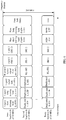
- the frame structure of the PPDU includes a legacy short training field (legacy short training field, L-STF), a legacy long training field (legacy long training field, L-LTF), a legacy signal field (legacy signal field, L-SIG), a high throughput signaling field (high throughput signaling field, HT-SIG), a high throughput short training field (high throughput short training field, HT-STF), a high throughput long training field (high throughput long training field, HT-LTF), and a data field (data field).
- L-STF, the L-LTF, and the L-SIG in the foregoing fields may be referred to as legacy preambles.
- the frame structure of the PPDU includes an L-STF, an L-LTF, an L-SIG, a very high throughput field A (very high throughput signaling field A, VHT-SIG-A), a very high throughput short training field (very high throughput short training field, VHT-STF), a very high throughput long training field (very high throughput long training field, VHT-LTF), a very high throughput field B (very high throughput signaling field B, VHT-SIG-B), and a data field.
- VHT-SIG-A very high throughput signaling field A
- VHT-STF very high throughput short training field
- VHT-LTF very high throughput long training field
- VHT-SIG-B very high throughput field B
- the PPDU in the embodiments of this application is mainly a next-generation Wi-Fi PPDU with an ultra-high bandwidth, and the foregoing frame structures of the PPDUs do not constitute a limitation on the embodiments of this application.
- FIG. 4 is a schematic flowchart of an information transmission method according to an embodiment of this application. Referring to FIG. 4 , the method includes the following several steps.
- Step 401 A wireless communications device generates a physical layer protocol data unit PPDU with a bandwidth of X MHz, where X>160, some or all fields in the PPDU are rotated in the bandwidth of X MHz by using a rotation factor sequence, the rotation factor sequence includes n rotation factors, the bandwidth of X MHz includes n bandwidths of Y MHz, and each bandwidth of Y MHz is corresponding to one rotation factor.
- the wireless communications device may be an AP or a STA.
- the AP may perform information transmission with another AP or an STA by using the PPDU with the bandwidth of X MHz.
- the wireless communications device is a STA, the STA may perform information transmission with an AP or another STA by using the PPDU with the bandwidth of X MHz.
- X MHz is greater than 160 MHz.
- X MHz may be 180 MHz, 200 MHz, 240 MHz, 280 MHz, 300 MHz, 320 MHz, or the like. This is not specifically limited in this embodiment of this application.
- Y MHz may be 20 MHz, 10 MHz, 5 MHz, 2 MHz, or the like. This is not specifically limited in this embodiment of this application.
- a value of each of the n rotation factors included in the rotation factor sequence may be 1, -1, j, or -j, where a rotation angle corresponding to the rotation factor 1 is 0 degrees, a rotation angle corresponding to the rotation factor -1 is 180 degrees, a rotation angle corresponding to the rotation factor j is 90 degrees, and a rotation angle corresponding to the rotation factor -j is -90 degrees.
- the PPDU may include a plurality of fields.
- the PPDU may include fields shown in FIG. 2 or FIG. 3 . That some or all fields in the PPDU are rotated in the bandwidth of X MHz by using a rotation factor sequence may include: some fields in the PPDU are rotated in the bandwidth of X MHz by using the rotation factor sequence, and the other fields in the PPDU are not rotated in the bandwidth of X MHz by using the rotation factor sequence; or all the fields in the PPDU are rotated in the bandwidth of X MHz by using the rotation factor sequence.
- some or all fields in the PPDU are rotated in the bandwidth of X MHz by using a rotation factor sequence
- each of the some or all fields in the PPDU is rotated in the bandwidth of X MHz by using the rotation factor sequence, that is, each field in the some fields in the PPDU is rotated in the n bandwidths of Y MHz by using the rotation factor sequence, or each field in the PPDU is rotated in the n bandwidths of Y MHz by using the rotation factor sequence.
- the X-MHz PPDU includes a plurality of fields in time domain, and includes n bandwidths of Y MHz in frequency domain. Each field in time domain is corresponding to n bandwidths of Y MHz in frequency domain. For the n bandwidths of Y MHz corresponding to each field, each of the n bandwidths of Y MHz may carry the field (that is, the n bandwidths of Y MHz corresponding to the field are fully occupied), or a blank bandwidth of Y MHz that does not carry the field may exist in the n bandwidths of Y MHz, but other fields do not occupy the blank bandwidth of Y MHz.
- each of the L-STF, the L-LTF, the L-SIG, and the HT-SIG field in the PPDU may be rotated in n bandwidths of Y MHz by using the rotation factor sequence, and each of the HT-STF, the HT-LTF, and the data field may not be rotated in the n bandwidths of Y MHz by using the rotation factor sequence.
- all the fields that is, the L-STF, the L-LTF, the L-SIG, the HT-SIG, the HT-STF, the HT-LTF, and the data field
- FIG. 2 all the fields (that is, the L-STF, the L-LTF, the L-SIG, the HT-SIG, the HT-STF, the HT-LTF, and the data field) shown in FIG. 2 are rotated in n bandwidths of Y MHz by using a rotation factor sequence.
- a transmission mode of some fields in the PPDU on the n bandwidths of Y MHz may be duplicate transmission, and the some fields may include the L-STF, the L-LTF, and the L-SIG.
- Each of the L-STF, the L-LTF, and the L-SIG may be rotated by using the rotation factor sequence, that is, a legacy preamble in the PPDU may be transmitted on the n bandwidths of Y MHz after being duplicated and rotated.
- Sequences of legacy preambles on all the bandwidths of Y MHz are the same, but the sequences of the legacy preambles are rotated at a specific angle on different bandwidths of Y MHz.
- a field in the PPDU other than the legacy preamble may be transmitted in a non - duplicate or duplicate mode, that is, content of the field other than the legacy preamble on all the bandwidths of Y MHz is different or the same.
- a maximum bandwidth of an 802.11n PPDU is 40 MHz
- a structure of the PPDU shown in FIG. 5 is a PPDU with an ultra-high bandwidth provided based on a structure of the 802.11n PPDU.
- This application is based on a structure of a next-generation Wi-Fi PPDU (a next generation of 802.11 ax) with an ultra-high bandwidth. Because a field included in the PPDU is unknown, the structure of the PPDU with the ultra-high bandwidth is shown in FIG. 6 .
- the structure of the PPDU includes a legacy preamble, a repeated legacy signal field (repeated legacy-signal field, RL-SIG), a signaling field 1 (signaling field 1, SIG 1), a signaling field 2 (signaling field 2, SIG 2), a new short training field (New short training field, NEW-STF), a new long training field (new long training field, NEW-LTF), and a data field (data).
- the PPDU may be an OFDMA PPDU, or may be a non-OFDMA PPDU. It should be noted that a field included in the next-generation PPDU does not constitute a limitation on an implementation of this application.
- a frequency domain signal corresponding to the some or all fields carried on each of the n bandwidths of Y MHz included in the bandwidth of X MHz may be multiplied by a rotation factor corresponding to the bandwidth of Y MHz, that is, products of the frequency domain signals corresponding to the some or all fields and a rotation factor sequence is obtained, and then inverse fast fourier transform (inverse fast fourier transform, IFFT) is performed on the products to obtain time-domain signals corresponding to the some or all fields.
- IFFT inverse fast fourier transform
- the frequency domain signals corresponding to the some or all fields are [Y1, Y2, ..., Yn]
- n rotation factors are [K1, K2, ..., Kn], where Y1 to Yn respectively represent the frequency domain signals corresponding to the n bandwidths of Y MHz, and K1 to Kn respectively represent rotation factors corresponding to the n bandwidths of Y MHz.
- the products of the frequency domain signals corresponding to the some or all fields and the rotation factor sequence may be represented as [Y1 ⁇ K1, Y2 ⁇ K2, ..., Yn ⁇ Kn], and the time-domain signals corresponding to the some or all fields may be represented as IFFT [Y1 ⁇ K1, Y2 ⁇ K2, ..., Yn ⁇ Kn].
- a peak to average power ratio peak to average power ratio (peak to average power ratio, PAPR) of the some or all fields based on the time-domain signals corresponding to the some or all fields
- oversampling may be performed on the time-domain signals corresponding to the some or all fields, to obtain an analog domain signal. For example, five-times oversampling is performed.
- a PAPR may be calculated according to the following formula (1).
- max represents an operation of solving a maximum value
- mean represents an averaging operation.
- PAPR 10 log 10 max S i 2 mean S i 2
- the PPDU with the bandwidth of X MHz includes a plurality of fields, and is transmitted on an X-MHz channel including n bandwidths of Y MHz. At least some fields in the PPDU carried on the n bandwidths of Y MHz are multiplied by n rotation factors in a vector in frequency domain in a one-to-one correspondence, where the at least some fields, carried on each bandwidth of Y MHz, of the PPDU are multiplied by a same coefficient of the rotation factor vector, that is, data carried on all subcarriers included in the bandwidths of Y MHz is multiplied by a same coefficient. In this way, PAPRs of the at least some fields in the PPDU are reduced.
- the fixed set to which the selected rotation factor belongs in this application is [1, -1, j, -j].
- an intermediate subcarrier of subcarriers at two sideband parts with the bandwidth of X MHz may carry no signal. In this way, adjacent-band interference and direct current interference can be avoided.
- each bandwidth of 20 MHz that carries a legacy preamble may alternatively include a sideband subcarrier, and carry no signal.
- Sequence numbers of the subcarriers included in the bandwidth of 80 MHz may be represented as -128 to 127.
- subcarriers whose subcarrier sequence numbers are -128 to -123 and 123 to 127 are subcarriers at a sideband part, and three subcarriers whose subcarrier sequence numbers are -1 to 1 are intermediate subcarriers. In this case, no signal may be carried on the subcarriers whose subcarrier sequence numbers are -128 to -123, 123 to 127, and -1 to 1.
- Sequence numbers of sideband subcarriers on the bandwidth of 20 MHz are -32 to -27 and 27 to 31. It should be noted that in this embodiment of this application, only the bandwidth of 80 MHz is used as an example for description. A bandwidth of X MHz greater than 160 MHz may also be designed according to the foregoing manner used for the bandwidth of 80 MHz. This is not described again in this embodiment of this application.
- Step 402 The wireless communications device sends the PPDU with the bandwidth of X MHz.
- the wireless communications device may send the PPDU with the bandwidth of X MHz to another wireless communications device.
- the wireless communications device on a receive side may perform corresponding rotation recovery on the received PPDU with the bandwidth of X MHz, to obtain the PPDU before rotation.
- a rotation factor is directly used as a part of a channel, and the rotation factor is removed through channel estimation and channel equalization.
- the wireless communications device on the receive side may alternatively perform rotation recovery on a field in the bandwidth of Y MHz by multiplying the field by a rotation factor.
- a rotation factor that is corresponding to the bandwidth of Y MHz and that is used on a transmit side 1, the rotation factor used when the corresponding rotation recovery is performed on the receive side may be 1, or the receive side does not perform rotation recovery on a field in a bandwidth of Y MHz corresponding to the rotation factor 1.
- the rotation factor used when the corresponding rotation recovery is performed on the receive side may be -1.
- the rotation factor used when the corresponding rotation recovery is performed on the receive side may be j.
- the rotation factor used when the corresponding rotation recovery is performed on the receive side may be -j.
- step 401 the method further includes step 400.
- Step 400 The wireless communications device selects the bandwidth of X MHz for transmitting the PPDU, where X MHz is any one of the following: 200 MHz, 240 MHz, 280 MHz, and 320 MHz.
- the wireless communications device may select, from a plurality of bandwidths, the bandwidth of X MHz for transmitting the PPDU, where the plurality of bandwidths may include 200 MHz, 240 MHz, 280 MHz, and 320 MHz, and the selected bandwidth of X MHz may be any one of 200 MHz, 240 MHz, 280 MHz, and 320 MHz.
- the rotation factor sequence may include a rotation factor corresponding to a current bandwidth of 80 MHz, or may not include the rotation factor corresponding to the current bandwidth of 80 MHz.
- the first four rotation factors in the rotation factor sequence are rotation factors corresponding to the current bandwidth of 80 MHz, that is, the first four rotation factors in the rotation factor sequence are [1 -1 -1 -1].
- a rotation angle corresponding to a rotation factor 1 is 0 degrees
- a rotation angle corresponding to a rotation factor -1 is 180 degrees
- a rotation angle corresponding to a rotation factor j is 90 degrees
- a rotation angle corresponding to a rotation factor -j is -90 degrees.
- 200 MHz is used as an example.
- a rotation angle sequence corresponding to a rotation factor sequence corresponding to 200 MHz is listed. To be specific, each rotation factor in the rotation factor sequence corresponding to 200 MHz is converted into a corresponding rotation angle, to obtain the corresponding rotation angle sequence.
- the rotation factor sequence includes the rotation factor corresponding to the current bandwidth of 80 MHz
- the rotation factor sequence corresponding to the bandwidth of 200 MHz starts from the four rotation factors corresponding to the current bandwidth of 80 MHz.
- the rotation factor sequence is specifically shown in the following Table 1-1, and a rotation angle sequence corresponding to the rotation factor sequence is [0 180 180 180 180 -90 90 -90 180 0].
- Table 1-1 Sequence number Rotation factor sequence 1 1 -1 -1 -1 -1 -1 -j j -j -1 1
- PAPRs corresponding to legacy preambles that is, the L-STF, the L-LTF, and the L-SIG field
- Table 1-2 Field L-STF L-LTF (including a cyclic prefix) L-LTF (excluding a cyclic prefix) L-SIG PAPR 3.5063 4.5770 4.5404 7.5778
- the rotation factor sequence corresponding to the bandwidth of 200 MHz may be any one of rotation factor sequences shown in the following Table 1-3.
- Table 1-3 Sequence number Rotation factor sequence 1 1 1 1 1 j -1 -j j -j -1 j 2 1 1 1 1 -j -1 j -j j -1 -j 3 1 1 j -1 -j j -j -1 j 1 4 1 1 -j -1 j -j j -1 -j 1 5 1 j 1 j 1 j 1 -j -1 j -1 -j 6 1 j 1 j 1 -1 -1 -j 1 -j -1 j 7 1 j 1 -j -1 j -1 j -1 -j 8 1 j 1 -j -1 j -1 -j 1 j 9 1 j j j 1 -j -1 1 -1 -j 10 1 j -1 1 -1 -1 -1 -1 -1 -1 -1
- PAPRs corresponding to legacy preambles that is, the L-STF, the L-LTF, and the L-SIG field
- Table 1-5 Field L-STF L-LTF (including a cyclic prefix) L-LTF (excluding a cyclic prefix) L-SIG PAPR 3.0566 3.9682 3.9321 7.0277
- the rotation factor sequence includes the rotation factor corresponding to the current bandwidth of 80 MHz
- the rotation factor sequence corresponding to the bandwidth of 240 MHz starts from the four rotation factors corresponding to the current bandwidth of 80 MHz.
- the rotation factor sequence is specifically shown in the following Table 2-1.
- PAPRs corresponding to legacy preambles that is, the L-STF, the L-LTF, and the L-SIG field
- Table 2-2 Field L-STF L-LTF (including a cyclic prefix) L-LTF (excluding a cyclic prefix) L-SIG PAPR 3.4872 4.4387 4.4026 7.4863
- the rotation factor sequence corresponding to the bandwidth of 240 MHz may be any one of rotation factor sequences shown in the following Table 2-3.
- Table 2-3 Sequence number Rotation factor sequence 1 1 1 1 1 1 1 1 -1 -1 1 -1 1 -1 1 -1 -1 2 1 1 1 1 1 -1 1 1 -1 1 -1 -1 -1 3 1 1 1 1 1 -1 -1 1 -1 -1 -1 1 4 1 1 1 1 -1 -1 -1 1 -1 1 1 1 -1 5 1 1 1 1 j 1 -1 1 1 1 -1 -j -1 -1 6 1 1 1 1 1 -1 1 1 1 -1 1 -1 -1 1 7 1 1 1 1 1 -1 1 -1 1 -1 -1 -1 -1 -1 8 1 1 1 1 -1 -1 1 -1 1 -1 1 1 9 1 1 1 1 -1 -1 j -1 1 1 -1 1 -j 10 1 1 1 1 -1 -1 -1 1 -1 1 1 1 11 1 1 1 1 -1 -1 -1 -1
- PAPRs corresponding to legacy preambles that is, the L-STF, the L-LTF, and the L-SIG field
- Table 2-4 PAPR L-STF L-LTF (including a cyclic prefix) L-LTF (excluding a cyclic prefix) L-SIG Table 2-3 Rotation factor sequence 3.4872 4.4387 4.4026 7.4863
- the rotation factor sequence includes the rotation factor corresponding to the current bandwidth of 80 MHz
- the rotation factor sequence corresponding to the bandwidth of 280 MHz starts from the four rotation factors corresponding to the current bandwidth of 80 MHz.
- the rotation factor sequence is specifically shown in the following Table 3-1.
- PAPRs corresponding to legacy preambles that is, the L-STF, the L-LTF, and the L-SIG field
- Table 3-2 Field L-STF L-LTF (including a cyclic prefix) L-LTF (excluding a cyclic prefix) L-SIG PAPR 2.2581 3.2044 3.1681 6.237
- the rotation factor sequence includes the rotation factor corresponding to the current bandwidth of 80 MHz
- the rotation factor sequence corresponding to the bandwidth of 320 MHz starts from the four rotation factors corresponding to the current bandwidth of 80 MHz.
- the rotation factor sequence is specifically shown in the following Table 4-1.
- PAPRs corresponding to legacy preambles that is, the L-STF, the L-LTF, and the L-SIG field
- Table 4-2 Field L-STF L-LTF (including a cyclic prefix) L-LTF (excluding a cyclic prefix) L-SIG PAPR 2.8488 3.7764 3.7403 6.8093
- the wireless communications device may generate and send the PPDU with the bandwidth of X MHz greater than 160 MHz, where the bandwidth of X MHz includes n bandwidths of Y MHz, some or all fields in the PPDU are rotated in the n bandwidths of Y MHz by using the rotation factor sequence, the rotation factor sequence includes n rotation factors, and each bandwidth of Y MHz is corresponding to one rotation factor. In this way, a PAPR of the PPDU can be reduced by using the rotation factor sequence.
- the PAPR of the PPDU can further be reduced by using the rotation factor sequence provided in this embodiment of this application, so that PAPRs of the some or all fields in the PPDU is minimized.
- an information transmission apparatus for example, an AP or a STA
- an information transmission apparatus includes corresponding hardware structures and/or software modules for performing the functions.
- a person skilled in the art should easily be aware that, in combination with units and algorithm steps of the examples described in the embodiments disclosed in this specification, this application may be implemented by hardware or a combination of hardware and computer software. Whether a function is performed by hardware or hardware driven by computer software depends on particular applications and design constraints of the technical solutions. A person skilled in the art may use different methods to implement the described functions for each particular application, but it should not be considered that the implementation goes beyond the scope of this application.
- the information transmission apparatus may be divided into function modules based on the foregoing method examples.
- each function module corresponding to each function may be obtained through division, or two or more functions may be integrated into one processing module.
- the function module may be implemented in a form of hardware, or may be implemented in a form of a software function module. It should be noted that, in the embodiments of this application, module division is used as an example, and is merely logical function division. In actual implementation, another division manner may be used. The following uses division of each function module based on a corresponding function as an example for description:
- FIG. 9 is a possible schematic structural diagram of the information transmission apparatus.
- the information transmission apparatus includes a generation unit 901 and a sending unit 902.
- the generation unit 901 is configured to support the information transmission apparatus in performing step 401 in the foregoing embodiment
- the sending unit 902 is configured to support the information transmission apparatus in performing step 402 in the foregoing embodiment.
- the information transmission apparatus may further include a selection unit 903.
- the selection unit 903 is configured to support the information transmission apparatus in performing step 400 in the foregoing embodiment. All related content of the steps in the foregoing method embodiments may be cited in function descriptions of corresponding function modules. Details are not described herein.
- FIG. 10 is another possible schematic structural diagram of the information transmission apparatus.
- the information transmission apparatus includes a processing module 1002 and a communications module 1003.
- the processing module 1002 is configured to control and manage actions of the information transmission apparatus.
- the processing module 1002 is configured to support the information transmission apparatus in performing step 400 and step 401 in the foregoing embodiment, and/or is configured to perform another technical process described in this specification.
- the communications module 1003 is configured to support the information transmission apparatus in performing step 402 in the foregoing embodiment.
- the information transmission apparatus may further include a storage module 1001 configured to store program code and data of the information transmission apparatus.
- the storage module 1001 is a memory
- the processing module 1002 may be a processor
- the communications module 1003 may be a communications interface.
- the communications interface may also be referred to as a transceiver, and the transceiver may be integration of a receiver and a transmitter.
- FIG. 11 is a structural diagram of a possible product form of the information transmission apparatus according to an embodiment of this application.
- the information transmission apparatus may be an information transmission device, and the information transmission device includes a processor 1102 and a transceiver 1103.
- the processor 1102 is configured to control and manage an action of the information transmission apparatus.
- the processor 1102 is configured to support the information transmission apparatus in performing step 400 and step 401 in the foregoing embodiment, and/or is configured to perform another technical process described in this specification.
- the transceiver 1103 is configured to support the information transmission apparatus in performing step 402 in the foregoing embodiment.
- the information transmission device may further include a memory 1101.
- the information transmission apparatus may be an information transmission board, and the information transmission board includes a processor 1102 and a transceiver 1103.
- the processor 1102 is configured to control and manage an action of the information transmission apparatus.
- the processor 1102 is configured to support the information transmission apparatus in performing step 400 and step 401 in the foregoing embodiment, and/or is configured to perform another technical process described in this specification.
- the transceiver 1103 is configured to support the information transmission apparatus in performing step 402 in the foregoing embodiment.
- the information transmission board may further include a memory 1101.
- the information transmission apparatus is also implemented by a general-purpose processor, namely, a commonly known chip.
- the general-purpose processor includes: a processor 1102 and a communications interface 1103.
- the general-purpose processor may further include a memory 1101.
- the information indication apparatus may also be implemented by using the following components: one or more FPGAs (field programmable gate arrays), a PLD (programmable logic device), a controller, a state machine, a gate logic, a discrete hardware component, any other suitable circuit, or any combination of circuits that can perform various functions described in this application.
- FPGAs field programmable gate arrays
- PLD programmable logic device
- controller a state machine
- gate logic a discrete hardware component
- any other suitable circuit any combination of circuits that can perform various functions described in this application.
- the processor 1102 may be a central processing unit, a general-purpose processor, a digital signal processor, an application-specific integrated circuit, a field programmable gate array or another programmable logical device, a transistor logical device, a hardware component, or any combination thereof.
- the processor may implement or execute various example logical blocks, modules, and circuits described with reference to the content disclosed in this application.
- the processor may be a combination of processors implementing a computing function, for example, a combination of one or more microprocessors, or a combination of the digital signal processor and a microprocessor.
- the bus 1104 may be a peripheral component interconnect (peripheral component interconnect, PCI) bus, an extended industry standard architecture (extended industry standard architecture, EISA) bus, or the like.
- the bus may be classified into an address bus, a data bus, a control bus, and the like. For ease of representation, only one thick line is used to represent the bus in FIG. 11 , but this does not mean that there is only one bus or
- the program instruction may be stored in a computer-readable storage medium.
- the foregoing storage medium includes any medium that can store program code, such as a USB flash drive, a removable hard disk, a ROM, a RAM, a magnetic disk, or an optical disc.
- an embodiment of this application further provides a readable storage medium.
- the readable storage medium stores a computer-executable instruction, and when the computer-executable instruction is run, a device (which may be a single-chip microcomputer, a chip, a controller, or the like) or a processor is enabled to perform the steps in the information transmission method provided in this application.
- an embodiment of this application further provides a computer program product.
- the computer program product includes a computer-executable instruction, and the computer-executable instruction is stored in a computer-readable storage medium, at least one processor of a device may read the computer-executable instruction from the computer-readable storage medium, and the at least one processor executes the computer-executable instruction, so that the device performs the steps in the information transmission method provided in this application.
- an information processing apparatus may generate a PPDU with a bandwidth of X MHz greater than 160 MHz and send the PPDU.
- the bandwidth of X MHz includes n bandwidth of Y MHz, some or all fields in the PPDU are rotated in the n bandwidths of Y MHz by using a rotation factor sequence, the rotation factor sequence includes n rotation factors, and each bandwidth of Y MHz corresponds to one rotation factor, so that a PAPR of the PPDU can be reduced by using the rotation factor sequence.
- the PAPR of the PPDU may be further reduced by using the rotation factor sequence provided in this embodiment of this application, so that PAPRs of some fields or all fields of the PPDU are optimal.
Landscapes
- Engineering & Computer Science (AREA)
- Computer Networks & Wireless Communication (AREA)
- Signal Processing (AREA)
- Mobile Radio Communication Systems (AREA)
- Electroluminescent Light Sources (AREA)
- Lubricants (AREA)
Applications Claiming Priority (2)
| Application Number | Priority Date | Filing Date | Title |
|---|---|---|---|
| CN201810278595.5A CN110324268B (zh) | 2018-03-31 | 2018-03-31 | 一种信息传输方法及装置 |
| PCT/CN2019/075498 WO2019184626A1 (fr) | 2018-03-31 | 2019-02-19 | Procédé et dispositif de transmission d'informations |
Publications (2)
| Publication Number | Publication Date |
|---|---|
| EP3780531A1 true EP3780531A1 (fr) | 2021-02-17 |
| EP3780531A4 EP3780531A4 (fr) | 2021-05-26 |
Family
ID=68062471
Family Applications (1)
| Application Number | Title | Priority Date | Filing Date |
|---|---|---|---|
| EP19776331.1A Pending EP3780531A4 (fr) | 2018-03-31 | 2019-02-19 | Procédé et dispositif de transmission d'informations |
Country Status (5)
| Country | Link |
|---|---|
| US (2) | US11528174B2 (fr) |
| EP (1) | EP3780531A4 (fr) |
| JP (2) | JP7057438B2 (fr) |
| CN (4) | CN117880037A (fr) |
| WO (1) | WO2019184626A1 (fr) |
Cited By (1)
| Publication number | Priority date | Publication date | Assignee | Title |
|---|---|---|---|---|
| WO2021262691A1 (fr) * | 2020-06-22 | 2021-12-30 | Qualcomm Incorporated | Long champ d'instruction à rapport réduit de puissances de crête à moyenne |
Families Citing this family (17)
| Publication number | Priority date | Publication date | Assignee | Title |
|---|---|---|---|---|
| CN117880037A (zh) * | 2018-03-31 | 2024-04-12 | 华为技术有限公司 | 一种信息传输方法及装置 |
| CN116366414A (zh) | 2018-07-27 | 2023-06-30 | 华为技术有限公司 | 设计短训练序列的方法和装置 |
| CN116743334B (zh) * | 2019-11-15 | 2024-03-01 | 华为技术有限公司 | 传输物理层协议数据单元的方法和装置 |
| CN113078987A (zh) * | 2020-01-03 | 2021-07-06 | 华为技术有限公司 | 传输物理层协议数据单元的方法和装置 |
| CN115362659B (zh) * | 2020-02-11 | 2024-05-07 | Lg电子株式会社 | 在无线lan系统中通过宽带接收ppdu的方法和设备 |
| WO2021194088A1 (fr) * | 2020-03-26 | 2021-09-30 | 엘지전자 주식회사 | Séquence d'apprentissage ltf de durée double pour 320 mhz |
| US20230121707A1 (en) | 2020-04-09 | 2023-04-20 | Lg Electronics Inc. | Method and device for applying phase rotation optimized for wide band in wireless lan system |
| US11962447B2 (en) | 2020-05-13 | 2024-04-16 | Lg Electronics Inc. | 4X LTF sequence for 80MHz band |
| CN116866133A (zh) * | 2020-05-18 | 2023-10-10 | 华为技术有限公司 | Ppdu传输方法及装置 |
| CN115988109B (zh) * | 2020-06-02 | 2024-02-13 | 华为技术有限公司 | 传输物理层协议数据单元的方法和装置 |
| CN116489242A (zh) * | 2020-06-05 | 2023-07-25 | 华为技术有限公司 | 传输/接收物理层协议数据单元的方法和装置 |
| CN114070695B (zh) * | 2020-07-31 | 2023-04-07 | 华为技术有限公司 | 传输eht-ltf序列的方法及相关装置 |
| CN116015579B (zh) * | 2020-08-03 | 2023-12-08 | 华为技术有限公司 | 一种传输物理层协议数据单元的方法及装置 |
| CN114070697B (zh) * | 2020-08-05 | 2023-02-10 | 华为技术有限公司 | 一种传输物理层协议数据单元的方法及装置 |
| WO2022033450A1 (fr) * | 2020-08-10 | 2022-02-17 | 华为技术有限公司 | Procédé et appareil d'envoi de données ainsi que procédé et appareil de réception de données |
| CN114339893A (zh) * | 2020-09-29 | 2022-04-12 | 华为技术有限公司 | 物理层协议数据单元ppdu传输方法及相关装置 |
| CN116886486A (zh) * | 2020-12-26 | 2023-10-13 | 华为技术有限公司 | 信息传输方法及装置 |
Family Cites Families (8)
| Publication number | Priority date | Publication date | Assignee | Title |
|---|---|---|---|---|
| CN101374125B (zh) * | 2007-08-24 | 2011-03-09 | 大唐移动通信设备有限公司 | 一种降低峰均比的方法和装置 |
| US8509324B2 (en) * | 2008-07-08 | 2013-08-13 | Qualcomm Incorporated | Methods and systems for reducing PAPR of an OFDM signal |
| US9131528B2 (en) * | 2012-04-03 | 2015-09-08 | Marvell World Trade Ltd. | Physical layer frame format for WLAN |
| US9258163B2 (en) | 2012-11-30 | 2016-02-09 | Qualcomm Incorporated | Systems and methods for phase rotating duplicate frames in wireless LAN transmission |
| US10375679B2 (en) * | 2014-12-05 | 2019-08-06 | Marvell World Trade Ltd. | Trigger frame format for orthogonal frequency division multiple access (OFDMA) communication |
| US9832058B2 (en) * | 2015-11-03 | 2017-11-28 | Newracom, Inc. | Apparatus and method for scrambling control field information for wireless communications |
| CN107040487B (zh) * | 2016-02-04 | 2021-06-15 | 中兴通讯股份有限公司 | 信号处理方法及装置 |
| CN117880037A (zh) * | 2018-03-31 | 2024-04-12 | 华为技术有限公司 | 一种信息传输方法及装置 |
-
2018
- 2018-03-31 CN CN202311682663.1A patent/CN117880037A/zh active Pending
- 2018-03-31 CN CN201810278595.5A patent/CN110324268B/zh active Active
- 2018-03-31 CN CN202311682777.6A patent/CN117880038A/zh active Pending
- 2018-03-31 CN CN202311684347.8A patent/CN117880039A/zh active Pending
-
2019
- 2019-02-19 WO PCT/CN2019/075498 patent/WO2019184626A1/fr unknown
- 2019-02-19 EP EP19776331.1A patent/EP3780531A4/fr active Pending
- 2019-02-19 JP JP2020552874A patent/JP7057438B2/ja active Active
-
2020
- 2020-09-29 US US17/036,996 patent/US11528174B2/en active Active
-
2022
- 2022-04-07 JP JP2022063944A patent/JP2022088659A/ja active Pending
- 2022-11-18 US US17/990,416 patent/US11792060B2/en active Active
Cited By (1)
| Publication number | Priority date | Publication date | Assignee | Title |
|---|---|---|---|---|
| WO2021262691A1 (fr) * | 2020-06-22 | 2021-12-30 | Qualcomm Incorporated | Long champ d'instruction à rapport réduit de puissances de crête à moyenne |
Also Published As
| Publication number | Publication date |
|---|---|
| WO2019184626A1 (fr) | 2019-10-03 |
| CN117880037A (zh) | 2024-04-12 |
| US20230155875A1 (en) | 2023-05-18 |
| CN117880038A (zh) | 2024-04-12 |
| JP2021517431A (ja) | 2021-07-15 |
| CN110324268A (zh) | 2019-10-11 |
| US11792060B2 (en) | 2023-10-17 |
| CN110324268B (zh) | 2023-12-15 |
| JP2022088659A (ja) | 2022-06-14 |
| JP7057438B2 (ja) | 2022-04-19 |
| EP3780531A4 (fr) | 2021-05-26 |
| CN117880039A (zh) | 2024-04-12 |
| US20210014097A1 (en) | 2021-01-14 |
| US11528174B2 (en) | 2022-12-13 |
Similar Documents
| Publication | Publication Date | Title |
|---|---|---|
| US11792060B2 (en) | Information transmission method and apparatus | |
| EP3151497B1 (fr) | Champ de signalisation de système de communication mimo sans fil et procédé de communication associé | |
| US10027512B2 (en) | Method and apparatus for sounding in wireless communication system | |
| US20230336396A1 (en) | Data transmission method and apparatus in wireless local area network | |
| EP3429148A1 (fr) | Procédé de mise en forme d'impulsions, émetteur, récepteur et système | |
| EP3222018B1 (fr) | Procédés et appareil pour émission/réception he-ltf | |
| EP3985909A1 (fr) | Appareil et procédé pour la transmission de dmrs | |
| US11469845B2 (en) | Data transmission method, apparatus, and system | |
| US20230344574A1 (en) | Information transmission method and apparatus | |
| EP4145784A1 (fr) | Procédé et appareil de transmission de ppdu | |
| WO2018036174A1 (fr) | Procédé de traitement de signaux de données et dispositif associé | |
| AU2017394106A1 (en) | Signal transmission method and apparatus | |
| US11444818B2 (en) | Signal transmission method and apparatus | |
| US11558233B2 (en) | WLAN baseband chip and FDMA PPDU generation method | |
| EP4040821B1 (fr) | Procédé et appareil pour émettre/recevoir une unité de données de protocole de couche physique | |
| WO2024098316A1 (fr) | Procédé et appareil de transmission de ppdu dans un système wi-fi, dispositif, et support |
Legal Events
| Date | Code | Title | Description |
|---|---|---|---|
| STAA | Information on the status of an ep patent application or granted ep patent |
Free format text: STATUS: THE INTERNATIONAL PUBLICATION HAS BEEN MADE |
|
| PUAI | Public reference made under article 153(3) epc to a published international application that has entered the european phase |
Free format text: ORIGINAL CODE: 0009012 |
|
| STAA | Information on the status of an ep patent application or granted ep patent |
Free format text: STATUS: REQUEST FOR EXAMINATION WAS MADE |
|
| 17P | Request for examination filed |
Effective date: 20201026 |
|
| AK | Designated contracting states |
Kind code of ref document: A1 Designated state(s): AL AT BE BG CH CY CZ DE DK EE ES FI FR GB GR HR HU IE IS IT LI LT LU LV MC MK MT NL NO PL PT RO RS SE SI SK SM TR |
|
| AX | Request for extension of the european patent |
Extension state: BA ME |
|
| A4 | Supplementary search report drawn up and despatched |
Effective date: 20210423 |
|
| RIC1 | Information provided on ipc code assigned before grant |
Ipc: H04L 27/26 20060101AFI20210419BHEP |
|
| DAV | Request for validation of the european patent (deleted) | ||
| DAX | Request for extension of the european patent (deleted) | ||
| STAA | Information on the status of an ep patent application or granted ep patent |
Free format text: STATUS: EXAMINATION IS IN PROGRESS |
|
| 17Q | First examination report despatched |
Effective date: 20220922 |