EP3780286A1 - Electric connector - Google Patents
Electric connector Download PDFInfo
- Publication number
- EP3780286A1 EP3780286A1 EP20189751.9A EP20189751A EP3780286A1 EP 3780286 A1 EP3780286 A1 EP 3780286A1 EP 20189751 A EP20189751 A EP 20189751A EP 3780286 A1 EP3780286 A1 EP 3780286A1
- Authority
- EP
- European Patent Office
- Prior art keywords
- panel
- main body
- water
- housing main
- fitting
- Prior art date
- Legal status (The legal status is an assumption and is not a legal conclusion. Google has not performed a legal analysis and makes no representation as to the accuracy of the status listed.)
- Granted
Links
Images



Classifications
-
- H—ELECTRICITY
- H01—ELECTRIC ELEMENTS
- H01R—ELECTRICALLY-CONDUCTIVE CONNECTIONS; STRUCTURAL ASSOCIATIONS OF A PLURALITY OF MUTUALLY-INSULATED ELECTRICAL CONNECTING ELEMENTS; COUPLING DEVICES; CURRENT COLLECTORS
- H01R13/00—Details of coupling devices of the kinds covered by groups H01R12/70 or H01R24/00 - H01R33/00
- H01R13/46—Bases; Cases
- H01R13/52—Dustproof, splashproof, drip-proof, waterproof, or flameproof cases
- H01R13/5219—Sealing means between coupling parts, e.g. interfacial seal
-
- H—ELECTRICITY
- H01—ELECTRIC ELEMENTS
- H01R—ELECTRICALLY-CONDUCTIVE CONNECTIONS; STRUCTURAL ASSOCIATIONS OF A PLURALITY OF MUTUALLY-INSULATED ELECTRICAL CONNECTING ELEMENTS; COUPLING DEVICES; CURRENT COLLECTORS
- H01R13/00—Details of coupling devices of the kinds covered by groups H01R12/70 or H01R24/00 - H01R33/00
- H01R13/46—Bases; Cases
- H01R13/52—Dustproof, splashproof, drip-proof, waterproof, or flameproof cases
- H01R13/5202—Sealing means between parts of housing or between housing part and a wall, e.g. sealing rings
-
- H—ELECTRICITY
- H01—ELECTRIC ELEMENTS
- H01R—ELECTRICALLY-CONDUCTIVE CONNECTIONS; STRUCTURAL ASSOCIATIONS OF A PLURALITY OF MUTUALLY-INSULATED ELECTRICAL CONNECTING ELEMENTS; COUPLING DEVICES; CURRENT COLLECTORS
- H01R13/00—Details of coupling devices of the kinds covered by groups H01R12/70 or H01R24/00 - H01R33/00
- H01R13/46—Bases; Cases
- H01R13/52—Dustproof, splashproof, drip-proof, waterproof, or flameproof cases
- H01R13/5213—Covers
-
- H—ELECTRICITY
- H01—ELECTRIC ELEMENTS
- H01R—ELECTRICALLY-CONDUCTIVE CONNECTIONS; STRUCTURAL ASSOCIATIONS OF A PLURALITY OF MUTUALLY-INSULATED ELECTRICAL CONNECTING ELEMENTS; COUPLING DEVICES; CURRENT COLLECTORS
- H01R13/00—Details of coupling devices of the kinds covered by groups H01R12/70 or H01R24/00 - H01R33/00
- H01R13/73—Means for mounting coupling parts to apparatus or structures, e.g. to a wall
- H01R13/74—Means for mounting coupling parts in openings of a panel
-
- H—ELECTRICITY
- H01—ELECTRIC ELEMENTS
- H01R—ELECTRICALLY-CONDUCTIVE CONNECTIONS; STRUCTURAL ASSOCIATIONS OF A PLURALITY OF MUTUALLY-INSULATED ELECTRICAL CONNECTING ELEMENTS; COUPLING DEVICES; CURRENT COLLECTORS
- H01R13/00—Details of coupling devices of the kinds covered by groups H01R12/70 or H01R24/00 - H01R33/00
- H01R13/73—Means for mounting coupling parts to apparatus or structures, e.g. to a wall
- H01R13/74—Means for mounting coupling parts in openings of a panel
- H01R13/746—Means for mounting coupling parts in openings of a panel using a screw ring
-
- H—ELECTRICITY
- H01—ELECTRIC ELEMENTS
- H01R—ELECTRICALLY-CONDUCTIVE CONNECTIONS; STRUCTURAL ASSOCIATIONS OF A PLURALITY OF MUTUALLY-INSULATED ELECTRICAL CONNECTING ELEMENTS; COUPLING DEVICES; CURRENT COLLECTORS
- H01R27/00—Coupling parts adapted for co-operation with two or more dissimilar counterparts
-
- H—ELECTRICITY
- H01—ELECTRIC ELEMENTS
- H01R—ELECTRICALLY-CONDUCTIVE CONNECTIONS; STRUCTURAL ASSOCIATIONS OF A PLURALITY OF MUTUALLY-INSULATED ELECTRICAL CONNECTING ELEMENTS; COUPLING DEVICES; CURRENT COLLECTORS
- H01R27/00—Coupling parts adapted for co-operation with two or more dissimilar counterparts
- H01R27/02—Coupling parts adapted for co-operation with two or more dissimilar counterparts for simultaneous co-operation with two or more dissimilar counterparts
-
- H—ELECTRICITY
- H01—ELECTRIC ELEMENTS
- H01R—ELECTRICALLY-CONDUCTIVE CONNECTIONS; STRUCTURAL ASSOCIATIONS OF A PLURALITY OF MUTUALLY-INSULATED ELECTRICAL CONNECTING ELEMENTS; COUPLING DEVICES; CURRENT COLLECTORS
- H01R13/00—Details of coupling devices of the kinds covered by groups H01R12/70 or H01R24/00 - H01R33/00
- H01R13/40—Securing contact members in or to a base or case; Insulating of contact members
- H01R13/42—Securing in a demountable manner
- H01R13/424—Securing in base or case composed of a plurality of insulating parts having at least one resilient insulating part
Definitions
- the present invention relates to an electric connector.
- an electric connector having a plurality of fitting ports to and from which cable connectors are connected and disconnected is known (for example, refer to patent literature 1 ( JP 2014-107046 )).
- the electric connector disclosed in patent literature 1 includes a housing having a cylindrical housing main body in which fitting ports are formed side by side and a pair of fixed parts protruding from the side face of the housing main body.
- a panel of the casing has an attachment hole into which a case part is insertable. In a state where the case part is inserted into the attachment hole from an inside of the casing and the case part is protruded from the outer face of the panel, the electric connector is fastened to the inner face of the panel via the pair of fixed parts using screws.
- the present invention is made in the above described view and it is therefore an object of the present invention to provide an electric connector of preventing infiltration of moisture into the inside of the casing and achieving space saving.
- an electric connector of one aspect of the present invention is an electric connector provided with a housing attached to an attachment hole of a panel of a casing, wherein the housing includes a housing main body inserted into the attachment hole of the panel and a flange part extending outward from an outer circumferential face of the housing main body, the housing main body has a plurality of fitting ports into which a plurality of cable connectors is fitted, on an outside of the casing, and the flange part has a fixed part fixed to the panel, wherein a first water-proof seal is installed to each of the fitting ports, the first water-proof seal seals between a circumferential wall of each of the fitting ports and each of the cable connectors, a second water-proof seal is installed around an outer circumferential face of the housing main body, and the second water-proof seal seals between the housing main body and the panel.
- An electric connector of one aspect of the present invention is fixed to the panel via the flange part in a state where the housing main body is inserted into the attachment hole of the panel and the housing main body is protruded from the panel. Because the plurality of fitting ports is formed in the housing main body on the outside of the casing, it is not required to prepare the connectors for each of the cable connectors, and therefore it becomes possible to decrease a number of installation work and to achieve space saving. Furthermore, the first water-proof seals prevent infiltration of moisture into the inside of the casing through the gaps between the circumferential walls of the fitting ports and the cable connectors. The second water-proof seal prevents filtration of moisture into the inside of the casing through the gap between the housing main body and the panel. Accordingly, it becomes possible to achieve space saving and to attach the electric connector to the panel which requires a high water-proof performance.
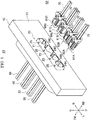
- FIG. 1 is a perspective view showing a receptacle connector and a cable connector in the present embodiment.
- a cable connector side of a panel is defined as a casing outside and an opposite side of the panel is defined as a casing inside.
- "FR", "RE”, “U”, “D”, “L” and “R”, marked in each figure respectively show a front direction, a rear direction, an upper direction, a lower direction, a left direction and a right direction.
- an example in which the receptacle connector in the present embodiment is applied to an electric power assist bicycle will be described.
- the receptacle connector (an electric connector) 20 is a composite connector attached to a panel 10 of a casing, and a plurality of cable connectors 60A to 60D (a counter connector) extending from an external unit, such as a lamp and a meter of the electric power assist bicycle, is connected to the receptacle connector 20.
- the panel 10 of the casing has a rectangular attachment hole 11 long in the left-and-right direction. Through the attachment hole 11, a rectangular cylindrical case part (a housing main body) 22 of the receptacle connector 20 is partially protruded from the outer face 13 of the panel 10.
- the protruded portion of the case part 22 has fitting ports 24A to 24D through which the cable connectors 60A to 60B are fitted into the fitting ports 24A to 24D.
- a plurality of cables 50 extending from an electric unit set in the casing inside S1 is connected to the receptacle connector 20 .
- the cable connectors 60A to 60D are formed to have different housing shapes.
- the fitting ports 24A to 24D of the receptacle connector 20 are formed to have shapes corresponding to the housing shapes of the cable connectors 60A to 60D.
- the receptacle connector 20 makes it possible to achieve space saving and improve workability of the connection work, compared with a case where the receptacle connectors are provided for each external unit. Because the fitting ports 24A to 24D of the receptacle connector 20 have different opening shapes for each type of the cable connectors 60A to 60D, it becomes possible to prevent misconnection of the connectors.
- the receptacle connector 20 is connected to the electric unit via the cables 50, but the receptacle connector 20 may be connected to a circuit board via a L-shaped terminal or the like.
- the receptacle connector 20 of the present embodiment includes first water-proof seals 40A to 40D which prevent infiltration of moisture into the casing inside S along the inner faces of the fitting ports 24A to 24D and a second water-proof seal 45 which prevents infiltration of moisture into the casing inside S1 along the outer face of the case part 22 (refer to FIG. 3 ).
- the cable connectors 60A to 60D include third water-proof seals which prevent infiltration of moisture into the casing inside S1 along the outer faces of the cables 75 ( FIG. 2 shows only the third water-proof seal 70B).
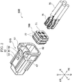
- FIG. 2 is a disassembled perspective view showing the cable connector in the present embodiment.
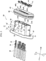
- FIG. 3 is a disassembled perspective view showing the receptacle connector in the present embodiment.
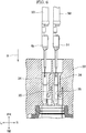
- FIG. 4A is a plan view showing the receptacle connector in the present embodiment, and FIG. 4B is a sectional view taken along the line A-A in FIG. 4A .
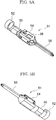
- FIG. 5A and FIG. 5B are perspective views showing a male type terminal in the present embodiment.
- FIG. 6 is an enlarged view partially showing a terminal storage space and its periphery in the present embodiment.
- FIG. 7 is a view showing an attachment state of the receptacle connector in the present embodiment.
- FIG. 8A is a front view showing the receptacle connector attached to the panel in the present embodiment, and FIG. 8B is a sectional view taken along the line B-B in FIG. 8A .
- the cable connector 60B is a signal cable connector, and includes an approximately rectangular cylindrical housing 61B extending in the front-and-rear direction.
- a plurality of terminal insertion ports (not shown) is formed, and in the rear end portion of the housing 61B, a rectangular opening 62 is formed.
- a female type terminal 76 connected to each cable 75 is stored through the opening 62.
- the female type terminals 76 are stored in the front end portion of the inside of the housing 61B.
- the front end face of each female type terminal 76 is exposed to an outside through the terminal insertion port of the housing 61B.
- the third water-proof seal 70B which seals between the housing 61B and the cables 75 is installed.
- the third water-proof seal 70B is made of elastic material, such as silicone rubber, formed into an approximately parallelepiped shape, and formed with a plurality of installation holes 71 along the front-and-rear direction into which the cables 75 are insertable tightly.
- the outer circumferential face of the third water-proof seal 70B comes into contact with the inner circumferential face of the housing 61B.
- a plurality of annular projections 72 each having a mountain-like sectional shape is formed.
- a lock mechanism 63 On the upper face of the housing 61B, a lock mechanism 63 is provided, and the lock mechanism 63 keeps the fitting state of the housing 61B of the cable connector 60B into the fitting port 24B of the receptacle connector 20 (refer to FIG. 3 ).
- the lock mechanism 63 has an arm part 64 extending rearward from the front side end portion of the housing 61B as a fixed end portion, a lock part 65 formed in a middle of the arm part 64 in its extending direction, and an operation part 66 provided in the free end portion of the arm part 64.
- the lock part 65 When the housing 61B is fitted into the fitting port 24B, the lock part 65 is engaged with a lock hole 25 (refer to FIG. 1 ) described later, and the fitting state is kept.
- the operation part 66 is pushed under the fitting state, the arm part 64 is pushed downward to disengage the lock part 65 from the lock hole 25 and then to release the fitting state.
- a pair of left and right protection parts 67 to protect the lock mechanism 63 is provided on the upper face of the housing 61B.
- the pair of left and right protection parts 67 prevents the arm part 64 from being deformed when an operator's hand or an article touches the operation part 66, and also prevents the lock mechanism 63 from being inoperable by inserting of the cable 75 and the like between the lock mechanism 63 and the housing 61B.
- the four-wire cable connector 60B has been described as an example, a three-wire, a six-wire and a two-wire cable connectors 60A, 60B and 60C have the same basic configuration as the above example. Then, the descriptions of the three-wire, six-wire and two-wire cable connectors 60A, 60B and 60C are omitted.
- the receptacle connector 20 includes a resin housing 21 attached to the panel 10 (refer to FIG. 1 ) of the casing.
- the housing 21 has the case part 22 inserted into the attachment hole 11 of the panel 10 and a flange part 23 extending outwardly in the radial direction from the front end side outer circumferential face of the case part 22.
- the case part 22 is formed into an approximately rectangular cylindrical shape extending in the front-and-rear direction and having a wide width in the left-and-right direction.
- a plurality of the lock holes 25 communicating with the fitting ports 24A to 24D is formed in the upper wall of the case part 22, a plurality of the lock holes 25 communicating with the fitting ports 24A to 24D is formed. With the lock holes 25, the lock parts 65 (refer to FIG. 3 ) of the cable connectors 60A to 60D are engaged.
- the fitting ports 24A to 24D having different opening shapes are formed side by side in the left-and-right direction.
- the fitting ports 24A to 24D extend from the rear end of the case part 22 to the center portion of the case part 22 in the front-and-rear direction.
- the fitting ports 24A to 24D are formed to have different opening shapes corresponding to the number of poles (the number of connection line of the cable 50).
- the fitting ports 24A to 24D are formed to have the opening shapes corresponding to the number of poles "three-wire”, "four-wire”, “six-wire” and "two-wire” respectively.
- the cable connectors 60A to 60D (refer to FIG. 1 ) are formed to have housing shapes corresponding to the opening shapes of the fitting ports 24A to 24D respectively.
- the first water-proof seals 40A to 40D are installed on the back faces of the fitting ports 24A to 24D.
- the first water-proof seals 40A to 40D seal between the circumferential walls 28 of the fitting ports 24A to 24D and the cable connectors 60A to 60D (refer to FIG. 1 ).
- the first water-proof seals 40A to 40D are made of elastic material, such as silicon rubber, and formed into annular shapes corresponding to the opening shapes of the fitting ports 24A to 24D, respectively.
- the first water-proof seals 40A to 40D each has a plurality of engagement pieces 41.
- the engagement pieces 41 By pushing the first water-proof seals 40A to 40D on the inner bottom face of the case part 22, the engagement pieces 41 are inserted into the engagement holes 27 formed in the circumferential wall 28 of the case part 22, and the first water-proof seals 40A to 40D installed to the insides of the fitting ports 24A to 24D are prevented from being removed.
- the second water-proof seal 45 is installed.
- the second water-proof seal 45 seals between the housing 21 and the panel 10.
- the second water-proof seal 45 is formed into an annular shape.
- the second water-proof seal 45 is pushed in the front end portion of the case part 22 such that the front end portion of the second water-proof seal 45 is fitted into an annular groove 33 of the flange part 23.
- the second water-proof seal 45 is positioned to the casing inside S1 (refer to FIG. 1 ) in a state where the receptacle connector 20 is attached to the panel 10.
- a gear or the like is stored in addition to the electric unit, and the gear is applied with grease as lubricant.
- the second water-proof seal 45 is made of elastic material having excellent oil resistant property.
- annular projections 46 having a mountain-like sectional shape is formed.
- annular projections 47 having a mountain-like sectional shape is formed.
- the annular projection 46 on the outer circumferential side has a protruding height higher than the annular projection 47 on the inner circumferential side, and the annular projection 46 on the outer circumferential side has a larger crushed amount.
- the annular projection 46 on the outer circumferential side is crushed to bring the second water-proof seal 45 into pressure-contact with the storage recess 15 of the panel 10.
- a pair of fixed parts 31 is formed so as to fix the receptacle connector 20 to the panel 10.
- the fixed part 31 has an insertion hole 32 for screwing.
- the outer circumferential face of the flange part 23 is formed asymmetrically in the upper-and-lower direction so as to prevent the receptacle connector 20 from being installed upside down.
- the annular groove 33 is formed so as to surround the case part 22.
- the annular groove 33 has the substantially same groove width as the thickness of the front end portion of the second water-proof seal 45.
- a plurality of terminal storage spaces 34 in which the male type terminals 51 connected to the cables 50 are stored is formed.
- the terminal storage space 34 is formed for each of the fitting ports 24A to 24D by the number of the connection wire of the corresponding cable 50.
- the terminal storage spaces 34 extend from the front end of the case part 22 to the fitting ports 24A to 24D.
- the terminal storage spaces 34 are communicated with the fitting ports 24A to 24D.
- the male type terminal 51 is made of electric conductive material, such as copper alloy, and formed by a cylindrical outer layer caulking part 52, a cylindrical core wire caulking part 53, a box-shaped middle part 54 and the pin-like contact 55 which are connected in the order from the base end side to the tip end side.
- the outer layer of the cable 50 is caulked by the outer layer caulking part 52, the core wire protruding from the outer layer of the cable 50 is caulked by the core wire caulking part 53, and then the male type terminal 51 is connected to the cable 50 (refer to FIG. 4B ).
- the middle part 54 is a portion stored in the terminal storage space 34 (refer to FIG. 4B ) of the case part 22, and on one side face of the middle part 54, a lance hole 56 engaged with a lance 35 described later is formed.
- the lance 35 with which the male type terminal 51 is engaged is provided on the inner wall of the terminal storage space 34 of the case part 22.
- the lance 35 is inclined so as to be separated from the inner wall of the terminal storage space 34 in the insertion direction I1 of the male type terminal 51.
- the lance 35 is pushed in, and then the male type terminal 51 is inserted to a predetermined position.
- the lance 35 is elastically returned and then the tip end portion of the lance 35 is inserted in the lance hole 56 (refer to FIG. 5A ) of the male type terminal 51. Then, the male type terminal 51 is fixed to the terminal storage space 34, and the cable 50 is prevented from being removed from the receptacle connector 20.
- the male type terminal 51 is installed to the receptacle connector 20 via the lance 35, the prevention of the removal of the male type terminal 51 by the lance 35 can be released by using a specific tool. Thereby, even if the male type terminal 51 is incorrectly inserted into the terminal storage space 34 of the receptacle connector 20, the prevention of the removal of the male type terminal 51 by the lance 35 can be released by using the specific tool, and it becomes possible to remove the male type terminal 51 from the receptacle connector 20 easily. In the above manner, because the male type terminal 51 connected to the cable 50 is directly installed to the receptacle connector 20, it becomes possible to make the connector configuration of the receptacle connector 20 simple and decrease the cost.
- the receptacle connector 20 is fixed to the panel 10 with a pair of bolts 39.
- the panel 10 has an annular protruded part 14.
- the annular protruded part 14 is protruded from the inner face 12 of the panel 10 to the casing inside S1 so as to surround the attachment hole 11.
- the storage recess 15 in which the receptacle connector 20 is stored is formed inside the annular protruded part 14.
- the storage recess 15 is formed to be front and rear two steps by a front step recess 16 in which the flange part 23 of the housing 21 is storable and a rear step recess 17 in which the second water-proof seal 45 installed to the case part 22 of the housing 21 is storable.
- the positioned flange part 23 of the housing 21 is stored.
- the inner circumferential face of the front step recess 16 is formed asymmetrically in the upper-and-lower direction corresponding to the upper-and-lower asymmetric outer circumferential face of the flange part 23.
- the flange part 23 is prevented from being stored in the front step recess 16 upside down, and it becomes possible to attach the receptacle connector 20 to the panel 10 in the correct orientation.
- a pair of screw holes 18 is formed at a position corresponding to the pair of insertion holes 32 of the flange part 23 in a state where the flange part 23 is stored to the front step recess 16.
- the second water-proof seal 45 installed to the case part 22 is tightly stored.
- the attachment hole 11 into which the case part 22 exposed from the second water-proof seal 45 is inserted is formed.
- FIG. 9A and FIG. 9B are transition diagrams showing the installation operation of the cable connector of the present embodiment.
- FIG. 10 is a sectional view showing the water-proof configuration of the receptacle connector of the present embodiment.
- the four-wire cable connector will be described as an example, and the three-wire, six-wire and two-wire cable connectors have the same configuration as the above example.
- the receptacle connector 20 is attached to the panel 10 with the case part 22 protruding from the outer face 13 of the panel 10.
- the first water-proof seal 40B is installed on the back face of the fitting port 24B of the case part 22 .
- the second water-proof seal 45 is installed.
- the annular projection 46 on the outer circumferential side of the second water-proof seal 45 is crushed by the inner circumferential face of the storage recess 15, and the annular projection 47 (refer to FIG. 3 ) on the inner circumferential side of the second water-proof seal 45 is crushed by the outer circumferential face of the case part 22.
- the second water-proof seal 45 seals between the storage recess 15 of the panel 10 and the case part 22.
- the third water-proof seal 70B is installed to the opening 62 in the rear end portion of the housing 61B.
- the cable 75 is tightly inserted into the installation hole 71 (refer to FIG. 2 ) of the third water-proof seal 70B.
- the annular projection 72 on the outer circumferential side of the third water-proof seal 70B is crushed by the inner circumferential face of the housing 61B.
- the third water-proof seal 70B seals the rear end portion of the housing 61B of the cable connector 60B. Then, the cable connector 60B is placed to face the opening of the fitting port 24B of the receptacle connector 20, and then the cable connector 60B is pushed in the fitting port 24B in the insertion direction 12.
- a slight gap is formed between the panel 10 and the receptacle connector 20, and a slight gap is formed between the receptacle connector 20 and the cable connector 60B. Then, in the portion where the receptacle connector 20 is attached, a moisture infiltration path from the casing outside S2 to the casing inside S1 exists.
- the moisture infiltration path contains a first infiltration path L1 along which moisture infiltrated from the lock hole 25 or the others of the case part 22 flows to the casing inside S1, a second infiltration path L2 along which moisture infiltrated through the gap between the case part 22 and the panel 10 flows to the casing inside S1, and a third infiltration path L3 along which moisture flows to the casing inside S1 through the cable 75 of the cable connector 60B.
- the first water-proof seal 40B is disposed on a middle of the first infiltration path L1.
- the first water-proof seal 40B seals between the circumferential wall 28 of the fitting port 24B and the housing 61B.
- the second water-proof seal 45 is disposed on a middle of the second infiltration path L2.
- the second water-proof seal 45 seals between the case part 22 and the storage recess 15 of the panel 10.
- the third water-proof seal 70B is disposed on a middle of the third infiltration path L3.
- the third water-proof seal 70B seals between the housing 61B and the cable 75.
- the case part 22 of the receptacle connector 20 is partially protruded from the outer face 13 of the panel 10, and separates the operation part 66 of the cable connector 60B from the outer face 13 of the panel 10.
- the plurality of lock holes 25 is formed for each of the fitting ports 24A to 24D (refer to FIG. 1 ).
- the operation parts 66 can be operated from the same upper side for the cable connectors 60A to 60D fitted into the fitting ports 24A to 24D, and the operation performance of the operation part 66 by the operator can be further improved.
- FIG. 11 is a perspective view showing the another using example of the receptacle connector in the present embodiment.
- the above described embodiment describes an example where the cable connectors 60A to 60D having different numbers of pole are installed to all of the fitting ports 24A to 24D of the receptacle connector 20, but the using example of the receptacle connector is not limited to the above example.
- the receptacle connector 20 of the present embodiment can be variously applied depending on requirement of the user. For example, as shown by the other using example in FIG. 11 , only three of the fitting ports 24A, 24B and 24D among the four fitting ports 24A to 24D (refer to FIG. 1 ) may be used, and the three-wire cable connector 60A and the four-wire cable connector 60B may be used as the two-wire cable connector.
- a cable connector shaped cap 80 is fitted into the unused fitting port 24C of the receptacle connector 20 into the unused fitting port 24C of the receptacle connector 20, a cable connector shaped cap 80 is fitted.
- the cap 80 has the same outer shape as the housing 61C (refer to FIG. 1 ) of the cable connector 60C only except that an inner space is not formed.
- the cap 80 is fitted into the unused fitting port 24C, and therefore, the first water-proof seal 40C (refer to FIG. 3 ) seals between the fitting port 24C and the cap 80. Thereby, it becomes possible to prevent infiltration of moisture through the unused fitting port 24C into the casing inside S1.
- the cables 75 are inserted into the two installation holes 71 among the three installation holes 71 of the third water-proof seal 70A while a water-proof rod 81 is inserted into the remaining one installation hole 71 tightly.
- the cables 75 are inserted into the two installation holes 71 among the four installation holes 71 while the water-proof rods 81 are inserted into the remaining two installation holes 71 tightly.
- the plurality of fitting ports 24A to 24D is formed on the casing outside S2 of the case part 22, it is not required to prepare the connectors for each of the cable connectors 60A to 60D, and therefore it becomes possible to decrease a number of installation work and to achieve space saving.
- the first water-proof seals 40A to 40D prevent infiltration of moisture into the casing inside S1 through the gaps between the circumferential walls 28 of the fitting ports 24A to 24D and the cable connectors 60A to 60D.
- the second water-proof seal 45 prevents filtration of moisture into the casing inside S1 through the gap between the case part 22 and the panel 10.
- the third water-proof seals 70A to 70D prevent infiltration of the moisture into the casing inside S1 through the cables 75 of the cable connectors 60A to 60D. Accordingly, it becomes possible to achieve space saving and to attach the receptacle connector 20 to the panel 10 which requires a high water-proof performance.
- the present embodiment describes the receptacle connector 20 having the case part 22 in which the fitting ports 24A to 24D are formed side by side in a row and attached to the panel 10 from the casing inside S1, but is not limited the above configuration.
- the receptacle connector 95 may have the case part 96 in which the fitting ports 98A to 98D are formed side by side in upper and lower two rows, and may be attached to the panel 90 from the casing outside S2.
- the first water-proof seals 101A to 101D are installed into the fitting ports 98A to 98D of the case part 96.
- the second water-proof seal 102 is installed.
- the flange part 97 is provided in the rear end portion of the case part 96, and the annular protruded part 92 is formed on the outer face 94 of the panel 90 so as to surround the attachment hole 91.
- the pair of screw holes 93 is formed on the face of the annular protruded part 92.
- a pair of bolts 100 is screwed to the pair of screw holes 93 through the pair of insertion holes 99 of the flange part 97, and then the receptacle connector 95 is attached to the panel 90.
- the cable connectors 103A to 103D are installed to the fitting ports 98A to 98D of the receptacle connector 95.
- the present embodiment describes the signal cable connector as a plurality of cable connector, but the plurality of cable connector may include a signal cable connector and a power cable connector.
- the case part 106 of the receptacle connector 105 may have a plurality of approximately rectangular fitting ports 107A to 107D for a plurality of the signal cable connectors and an approximately circular fitting port 108 for the power cable connector.
- the present embodiment describes an example where the receptacle connector is used for the electric power assist bicycle, but the receptacle connector may be used for a vehicle such as an electric power scooter and an electric power wheelchair, an apparatus requiring a water-proof performance and the like.
- the fitting ports of the receptacle connector are formed to have different opening shapes, but the fitting ports of the receptacle connector may be formed to have the same opening shape.
- the second water-proof seal is made of elastic material having oil resistant property, but in a case where the receptacle connector is attached to an apparatus which does not use lubricant, such as grease, the second water-proof seal may be made of elastic material, such as silicon rubber.
- the outer circumferential face of the flange part is formed asymmetrically in the upper-and-lower direction, but the outer circumferential face of the flange part may be formed rotationally asymmetrically.
- the outer circumferential face of the flange part may be formed asymmetrically in the left-and-right direction.
- the case part is protruded from the outer face of the panel, but the case part may not be protruded from the outer face of the panel.
- the case part may be formed to expose the plurality of fitting ports from the outer face of the panel so as to be connected to the cable connectors.
- the flange part extends outwardly in the radial direction from all the outer circumferential face of the case part, but the flange part may extend outwardly in the radial direction from at least a part of the outer circumferential face of the case part.
- the electric connector (the receptacle connector) of the present embodiment is an electric connector provided with a housing (21) attached to an attachment hole (11) of a panel (10) of a casing, wherein the housing includes a housing main body (the case part 22) inserted into the attachment hole of the panel and a flange part (23) extending outward from an outer circumferential face of the housing main body, the housing main body has a plurality of fitting ports (24A to 24D) into which a plurality of cable connectors (60A to 60D) is fitted, on an outside (S2) of the casing, and the flange part has a fixed part (31) fixed to the panel, wherein a first water-proof seal (40A to 40D) is installed to each of the fitting ports, the first water-proof seal seals between a circumferential wall (28) of each of the fitting ports and each of the cable connectors, a second water-proof seal (45) is installed around an outer circumferential face of the housing main body, and the second water-
- the electric connector is fixed to the panel via the flange part in a state where the housing main body is inserted into the attachment hole of the panel and the housing main body is protruded from the panel. Because the plurality of fitting ports is formed in the housing main body on the outside of the casing, it is not required to prepare the connectors for each of the cable connectors, and therefore it becomes possible to decrease a number of installation work and to achieve space saving. Additionally, the first water-proof seals prevent infiltration of moisture into the casing inside through the gaps between the circumferential walls of the fitting ports and the cable connectors. The second water-proof seal prevents filtration of moisture into the casing inside through the gap between the housing main body and the panel. Accordingly, it becomes possible to achieve space saving and to attach the electric connector to the panel which requires a high water-proof performance.
- the fitting ports are formed to have different opening shapes. According to the configuration, it becomes possible to prevent the plurality of cable connectors from being incorrectly connected to the plurality of fitting ports.
- the housing main body has a terminal storage recess (34) in which a terminal (the male type connector 51) connected to a cable is stored, on an inside (S1) of the casing, and a lance (35) to prevent removing of the terminal is formed on an inner wall of the terminal storage recess.
- an outer circumferential face of the flange part is formed rotationally asymmetrically, and the panel has a storage recess (15) in which the flange part is stored with being positioned.
- the flange part is stored in the storage recess of the panel in a predetermined orientation so that it becomes possible to install the electric connecter with a correct orientation.
- the housing main body has a plurality of lock holes (25) communicated with the plurality of fitting ports
- the cable connectors each has a lock part (65) engaged with each of the lock holes and an operation part (66) to be operated so as to disengage each of the lock parts from each of the lock holes
- the housing main body is protruded from an outer face of the panel so as to separate the operation part of the cable connector from the outer face of the panel.
- the fitting ports are aligned side by side in a long side direction of the housing main body, and the lock holes are formed on one end face in a short side direction of the housing main body. According to the configuration, because the operation parts can be operated from the same side for the cable connectors fitted into the respective fitting ports, it becomes possible to heighten the operation performance of the operation part.
- a cable connector shaped cap (80) is fitted into an unused fitting port among the fitting ports.
- the first water-proof seal seals the gap between the unused fitting port and the cable connector shaped cap so that infiltration of moisture from the unused fitting port to the inner face of the panel can be prevented.
- the cable connectors contain a signal cable connector and a power cable connector
- the fitting ports contain a fitting port (107A to 107D) for the signal cable connector and a fitting port (108) for the power cable connector.
- the technique of the present invention is not limited to the above described embodiments, and may be modified, substituted or deformed in various ways without departing from the sprit of the technical idea. Furthermore, if the technical idea can be realized in another way by development of technology and another derived technology, it may be carried out by using the way. Accordingly, the claims cover all embodiments that may be included within the scope of the technical idea.
Landscapes
- Connector Housings Or Holding Contact Members (AREA)
- Details Of Connecting Devices For Male And Female Coupling (AREA)
Abstract
Description
- The present invention relates to an electric connector.
- As an electric connector fixed to a panel of a casing, an electric connector having a plurality of fitting ports to and from which cable connectors are connected and disconnected is known (for example, refer to patent literature 1 (
JP 2014-107046 patent literature 1 includes a housing having a cylindrical housing main body in which fitting ports are formed side by side and a pair of fixed parts protruding from the side face of the housing main body. A panel of the casing has an attachment hole into which a case part is insertable. In a state where the case part is inserted into the attachment hole from an inside of the casing and the case part is protruded from the outer face of the panel, the electric connector is fastened to the inner face of the panel via the pair of fixed parts using screws. - By the way, such an electric connector is sometimes attached to a portion where a high water-proof performance is required. Although the above described electric connector does not require to be prepared individually for each cable connector and allows space saving, there is a problem in which infiltration of moisture into the inside of the casing is not sufficiently prevented.
- The present invention is made in the above described view and it is therefore an object of the present invention to provide an electric connector of preventing infiltration of moisture into the inside of the casing and achieving space saving.
- To achieve the object, an electric connector of one aspect of the present invention is an electric connector provided with a housing attached to an attachment hole of a panel of a casing, wherein the housing includes a housing main body inserted into the attachment hole of the panel and a flange part extending outward from an outer circumferential face of the housing main body, the housing main body has a plurality of fitting ports into which a plurality of cable connectors is fitted, on an outside of the casing, and the flange part has a fixed part fixed to the panel, wherein a first water-proof seal is installed to each of the fitting ports, the first water-proof seal seals between a circumferential wall of each of the fitting ports and each of the cable connectors, a second water-proof seal is installed around an outer circumferential face of the housing main body, and the second water-proof seal seals between the housing main body and the panel.
- An electric connector of one aspect of the present invention is fixed to the panel via the flange part in a state where the housing main body is inserted into the attachment hole of the panel and the housing main body is protruded from the panel. Because the plurality of fitting ports is formed in the housing main body on the outside of the casing, it is not required to prepare the connectors for each of the cable connectors, and therefore it becomes possible to decrease a number of installation work and to achieve space saving. Furthermore, the first water-proof seals prevent infiltration of moisture into the inside of the casing through the gaps between the circumferential walls of the fitting ports and the cable connectors. The second water-proof seal prevents filtration of moisture into the inside of the casing through the gap between the housing main body and the panel. Accordingly, it becomes possible to achieve space saving and to attach the electric connector to the panel which requires a high water-proof performance.
-
-
FIG. 1 is a perspective view showing a receptacle connector and a cable connector in the present embodiment; -
FIG. 2 is a disassembled perspective view showing the cable connector in the present embodiment; -
FIG. 3 is a disassembled perspective view showing the receptacle connector in the present embodiment; -
FIG. 4A is a plan view showing the receptacle connector in the present embodiment; -
FIG. 4B is a sectional view taken along the line A-A inFIG. 4A ; -
FIG. 5A is a perspective view showing a male type terminal in the present embodiment; -
FIG. 5B is a perspective view showing the male type terminal in the present embodiment; -
FIG. 6 is a partially enlarged view showing a terminal storage space and its periphery in the present embodiment; -
FIG. 7 is a view showing an attachment state of the receptacle connector in the present embodiment; -
FIG. 8A is a front view showing the receptacle connector attached to a panel in the present embodiment; -
FIG. 8B is a sectional view taken along the line B-B inFIG. 8A ; -
FIG. 9A is a transition diagram of a connection operation of the cable connector in the present embodiment; -
FIG. 9B is a transition diagram of the connection operation of the cable connector in the present embodiment; -
FIG. 10 is a sectional view showing a water-proof configuration of the receptacle connector in the present embodiment; -
FIG. 11 is a perspective view showing another using example of the receptacle connector in the present example; -
FIG. 12A is a perspective view showing the receptacle connector in a modified example; -
FIG. 12B is a perspective view showing the receptacle connector in the modified example; and -
FIG. 13 is a front view showing the receptacle connector in another modified example. - Hereinafter, with reference to the attached drawings, the present embodiment will be described.
FIG. 1 is a perspective view showing a receptacle connector and a cable connector in the present embodiment. In the following description, a cable connector side of a panel is defined as a casing outside and an opposite side of the panel is defined as a casing inside. "FR", "RE", "U", "D", "L" and "R", marked in each figure respectively show a front direction, a rear direction, an upper direction, a lower direction, a left direction and a right direction. Hereinafter, an example in which the receptacle connector in the present embodiment is applied to an electric power assist bicycle will be described. - As shown in
FIG. 1 , the receptacle connector (an electric connector) 20 is a composite connector attached to apanel 10 of a casing, and a plurality ofcable connectors 60A to 60D (a counter connector) extending from an external unit, such as a lamp and a meter of the electric power assist bicycle, is connected to thereceptacle connector 20. Thepanel 10 of the casing has arectangular attachment hole 11 long in the left-and-right direction. Through theattachment hole 11, a rectangular cylindrical case part (a housing main body) 22 of thereceptacle connector 20 is partially protruded from theouter face 13 of thepanel 10. The protruded portion of thecase part 22 hasfitting ports 24A to 24D through which thecable connectors 60A to 60B are fitted into thefitting ports 24A to 24D. - To the
receptacle connector 20, a plurality ofcables 50 extending from an electric unit set in the casing inside S1 is connected. By fitting thecable connectors 60A to 60D into thefitting ports 24A to 24D of thereceptacle connector 20, the electric unit set in the casing inside S1 is electrically connected to the various external units set in the casing outside S2. In order to prevent misconnection between the connectors, thecable connectors 60A to 60D are formed to have different housing shapes. Thefitting ports 24A to 24D of thereceptacle connector 20 are formed to have shapes corresponding to the housing shapes of thecable connectors 60A to 60D. - As described above, by concentrating the
cable connectors 60A to 60D extending from the external units in the same portion, thereceptacle connector 20 makes it possible to achieve space saving and improve workability of the connection work, compared with a case where the receptacle connectors are provided for each external unit. Because thefitting ports 24A to 24D of thereceptacle connector 20 have different opening shapes for each type of thecable connectors 60A to 60D, it becomes possible to prevent misconnection of the connectors. In the present embodiment, thereceptacle connector 20 is connected to the electric unit via thecables 50, but thereceptacle connector 20 may be connected to a circuit board via a L-shaped terminal or the like. - Additionally, because various electric components are stored in the casing inside S1, a high water-proof performance is required for the attachment portion of the
receptacle connector 20 to thepanel 10 of the casing. Then, thereceptacle connector 20 of the present embodiment includes first water-proof seals 40A to 40D which prevent infiltration of moisture into the casing inside S along the inner faces of thefitting ports 24A to 24D and a second water-proof seal 45 which prevents infiltration of moisture into the casing inside S1 along the outer face of the case part 22 (refer toFIG. 3 ). Furthermore, thecable connectors 60A to 60D include third water-proof seals which prevent infiltration of moisture into the casing inside S1 along the outer faces of the cables 75 (FIG. 2 shows only the third water-proof seal 70B). - Hereinafter, configurations of the cable connector and the receptacle connector will be described in detail.
FIG. 2 is a disassembled perspective view showing the cable connector in the present embodiment.FIG. 3 is a disassembled perspective view showing the receptacle connector in the present embodiment.FIG. 4A is a plan view showing the receptacle connector in the present embodiment, andFIG. 4B is a sectional view taken along the line A-A inFIG. 4A .FIG. 5A and FIG. 5B are perspective views showing a male type terminal in the present embodiment.FIG. 6 is an enlarged view partially showing a terminal storage space and its periphery in the present embodiment.FIG. 7 is a view showing an attachment state of the receptacle connector in the present embodiment.FIG. 8A is a front view showing the receptacle connector attached to the panel in the present embodiment, andFIG. 8B is a sectional view taken along the line B-B inFIG. 8A . - As shown in
FIG. 2 , thecable connector 60B is a signal cable connector, and includes an approximately rectangularcylindrical housing 61B extending in the front-and-rear direction. In the front end portion of thehousing 61B, a plurality of terminal insertion ports (not shown) is formed, and in the rear end portion of thehousing 61B, arectangular opening 62 is formed. Inside thehousing 61B, afemale type terminal 76 connected to eachcable 75 is stored through theopening 62. Thefemale type terminals 76 are stored in the front end portion of the inside of thehousing 61B. The front end face of eachfemale type terminal 76 is exposed to an outside through the terminal insertion port of thehousing 61B. - To the
opening 62 of thehousing 61B, the third water-proof seal 70B which seals between thehousing 61B and thecables 75 is installed. The third water-proof seal 70B is made of elastic material, such as silicone rubber, formed into an approximately parallelepiped shape, and formed with a plurality of installation holes 71 along the front-and-rear direction into which thecables 75 are insertable tightly. The outer circumferential face of the third water-proof seal 70B comes into contact with the inner circumferential face of thehousing 61B. Around the outer circumferential face of the third water-proof seal 70B, a plurality ofannular projections 72 each having a mountain-like sectional shape is formed. By installing the third water-proof seal 70B to theopening 62 of thehousing 61B, the plurality ofannular projections 72 is slightly crushed to bring the third water-proof seal 70B into pressure-contact with thehousing 61B. - On the upper face of the
housing 61B, alock mechanism 63 is provided, and thelock mechanism 63 keeps the fitting state of thehousing 61B of thecable connector 60B into thefitting port 24B of the receptacle connector 20 (refer toFIG. 3 ). Thelock mechanism 63 has anarm part 64 extending rearward from the front side end portion of thehousing 61B as a fixed end portion, alock part 65 formed in a middle of thearm part 64 in its extending direction, and anoperation part 66 provided in the free end portion of thearm part 64. When thehousing 61B is fitted into thefitting port 24B, thelock part 65 is engaged with a lock hole 25 (refer toFIG. 1 ) described later, and the fitting state is kept. When theoperation part 66 is pushed under the fitting state, thearm part 64 is pushed downward to disengage thelock part 65 from thelock hole 25 and then to release the fitting state. - On the upper face of the
housing 61B, a pair of left andright protection parts 67 to protect thelock mechanism 63 is provided. The pair of left andright protection parts 67 prevents thearm part 64 from being deformed when an operator's hand or an article touches theoperation part 66, and also prevents thelock mechanism 63 from being inoperable by inserting of thecable 75 and the like between thelock mechanism 63 and thehousing 61B. Here, although the four-wire cable connector 60B has been described as an example, a three-wire, a six-wire and a two-wire cable connectors wire cable connectors - As shown in
FIG. 3 ,FIG. 4A and FIG. 4B , thereceptacle connector 20 includes aresin housing 21 attached to the panel 10 (refer toFIG. 1 ) of the casing. Thehousing 21 has thecase part 22 inserted into theattachment hole 11 of thepanel 10 and aflange part 23 extending outwardly in the radial direction from the front end side outer circumferential face of thecase part 22. Thecase part 22 is formed into an approximately rectangular cylindrical shape extending in the front-and-rear direction and having a wide width in the left-and-right direction. In the upper wall of thecase part 22, a plurality of the lock holes 25 communicating with thefitting ports 24A to 24D is formed. With the lock holes 25, the lock parts 65 (refer toFIG. 3 ) of thecable connectors 60A to 60D are engaged. - In the rear end portion of the
case part 22, thefitting ports 24A to 24D having different opening shapes are formed side by side in the left-and-right direction. Thefitting ports 24A to 24D extend from the rear end of thecase part 22 to the center portion of thecase part 22 in the front-and-rear direction. Thefitting ports 24A to 24D are formed to have different opening shapes corresponding to the number of poles (the number of connection line of the cable 50). For example, thefitting ports 24A to 24D are formed to have the opening shapes corresponding to the number of poles "three-wire", "four-wire", "six-wire" and "two-wire" respectively. Thecable connectors 60A to 60D (refer toFIG. 1 ) are formed to have housing shapes corresponding to the opening shapes of thefitting ports 24A to 24D respectively. - On the back faces of the
fitting ports 24A to 24D, the first water-proof seals 40A to 40D are installed. The first water-proof seals 40A to 40D seal between thecircumferential walls 28 of thefitting ports 24A to 24D and thecable connectors 60A to 60D (refer toFIG. 1 ). The first water-proof seals 40A to 40D are made of elastic material, such as silicon rubber, and formed into annular shapes corresponding to the opening shapes of thefitting ports 24A to 24D, respectively. The first water-proof seals 40A to 40D each has a plurality ofengagement pieces 41. By pushing the first water-proof seals 40A to 40D on the inner bottom face of thecase part 22, theengagement pieces 41 are inserted into the engagement holes 27 formed in thecircumferential wall 28 of thecase part 22, and the first water-proof seals 40A to 40D installed to the insides of thefitting ports 24A to 24D are prevented from being removed. - Around the outer circumferential face of the
case part 22, the second water-proof seal 45 is installed. The second water-proof seal 45 seals between thehousing 21 and thepanel 10. The second water-proof seal 45 is formed into an annular shape. The second water-proof seal 45 is pushed in the front end portion of thecase part 22 such that the front end portion of the second water-proof seal 45 is fitted into anannular groove 33 of theflange part 23. Thereby, the second water-proof seal 45 is positioned to the casing inside S1 (refer toFIG. 1 ) in a state where thereceptacle connector 20 is attached to thepanel 10. In the casing inside S1, a gear or the like is stored in addition to the electric unit, and the gear is applied with grease as lubricant. Thereby, the second water-proof seal 45 is made of elastic material having excellent oil resistant property. - Around the outer circumferential face of the second water-
proof seal 45, a plurality ofannular projections 46 having a mountain-like sectional shape is formed. Around the inner circumferential face of the second water-proof seal 45, a plurality ofannular projections 47 having a mountain-like sectional shape is formed. Theannular projection 46 on the outer circumferential side has a protruding height higher than theannular projection 47 on the inner circumferential side, and theannular projection 46 on the outer circumferential side has a larger crushed amount. By installing the second water-proof seal 45 around the outer circumferential face of thecase part 22, theannular projection 47 on the inner circumferential side is crushed to bring the second water-proof seal 45 into pressure-contact with thecase part 22. Furthermore, by inserting the second water-proof seal 45 into the storage recess 15 (refer toFIG. 7 ) of thepanel 10, theannular projection 46 on the outer circumferential side is crushed to bring the second water-proof seal 45 into pressure-contact with thestorage recess 15 of thepanel 10. - In both the left and right end portions of the
flange part 23, a pair of fixedparts 31 is formed so as to fix thereceptacle connector 20 to thepanel 10. Thefixed part 31 has aninsertion hole 32 for screwing. The outer circumferential face of theflange part 23 is formed asymmetrically in the upper-and-lower direction so as to prevent thereceptacle connector 20 from being installed upside down. In theflange part 23, theannular groove 33 is formed so as to surround thecase part 22. Theannular groove 33 has the substantially same groove width as the thickness of the front end portion of the second water-proof seal 45. By inserting the front end portion of the second water-proof seal 45 into theannular groove 33, a seal performance between theflange part 23 and the second water-proof seal 45 is improved. - In the front end portion of the
case part 22, a plurality ofterminal storage spaces 34 in which themale type terminals 51 connected to thecables 50 are stored is formed. Theterminal storage space 34 is formed for each of thefitting ports 24A to 24D by the number of the connection wire of the correspondingcable 50. Theterminal storage spaces 34 extend from the front end of thecase part 22 to thefitting ports 24A to 24D. Theterminal storage spaces 34 are communicated with thefitting ports 24A to 24D. When themale type terminals 51 are stored in the correspondingterminal storage spaces 34 from the front end side of thecase part 22, the pin-like contacts 55 of themale type terminals 51 are protruded from the back faces of thefitting ports 24A to 24D. - As shown in
FIG. 5A and FIG. 5B , themale type terminal 51 is made of electric conductive material, such as copper alloy, and formed by a cylindrical outerlayer caulking part 52, a cylindrical corewire caulking part 53, a box-shapedmiddle part 54 and the pin-like contact 55 which are connected in the order from the base end side to the tip end side. The outer layer of thecable 50 is caulked by the outerlayer caulking part 52, the core wire protruding from the outer layer of thecable 50 is caulked by the corewire caulking part 53, and then themale type terminal 51 is connected to the cable 50 (refer toFIG. 4B ). Themiddle part 54 is a portion stored in the terminal storage space 34 (refer toFIG. 4B ) of thecase part 22, and on one side face of themiddle part 54, alance hole 56 engaged with alance 35 described later is formed. - As shown in
FIG. 6 , on the inner wall of theterminal storage space 34 of thecase part 22, thelance 35 with which themale type terminal 51 is engaged is provided. Thelance 35 is inclined so as to be separated from the inner wall of theterminal storage space 34 in the insertion direction I1 of themale type terminal 51. When themale type terminal 51 is inserted into theterminal storage space 34, thelance 35 is pushed in, and then themale type terminal 51 is inserted to a predetermined position. When themale type terminal 51 is positioned to the predetermined position, thelance 35 is elastically returned and then the tip end portion of thelance 35 is inserted in the lance hole 56 (refer toFIG. 5A ) of themale type terminal 51. Then, themale type terminal 51 is fixed to theterminal storage space 34, and thecable 50 is prevented from being removed from thereceptacle connector 20. - Because the
male type terminal 51 is installed to thereceptacle connector 20 via thelance 35, the prevention of the removal of themale type terminal 51 by thelance 35 can be released by using a specific tool. Thereby, even if themale type terminal 51 is incorrectly inserted into theterminal storage space 34 of thereceptacle connector 20, the prevention of the removal of themale type terminal 51 by thelance 35 can be released by using the specific tool, and it becomes possible to remove themale type terminal 51 from thereceptacle connector 20 easily. In the above manner, because themale type terminal 51 connected to thecable 50 is directly installed to thereceptacle connector 20, it becomes possible to make the connector configuration of thereceptacle connector 20 simple and decrease the cost. - As shown in
FIG. 7 ,FIG. 8A and FIG. 8B , thereceptacle connector 20 is fixed to thepanel 10 with a pair ofbolts 39. Thepanel 10 has an annular protrudedpart 14. The annular protrudedpart 14 is protruded from theinner face 12 of thepanel 10 to the casing inside S1 so as to surround theattachment hole 11. Inside the annular protrudedpart 14, thestorage recess 15 in which thereceptacle connector 20 is stored is formed. Thestorage recess 15 is formed to be front and rear two steps by afront step recess 16 in which theflange part 23 of thehousing 21 is storable and arear step recess 17 in which the second water-proof seal 45 installed to thecase part 22 of thehousing 21 is storable. - In the
front step recess 16 of thestorage recess 15, the positionedflange part 23 of thehousing 21 is stored. In detail, the inner circumferential face of thefront step recess 16 is formed asymmetrically in the upper-and-lower direction corresponding to the upper-and-lower asymmetric outer circumferential face of theflange part 23. Thereby, theflange part 23 is prevented from being stored in thefront step recess 16 upside down, and it becomes possible to attach thereceptacle connector 20 to thepanel 10 in the correct orientation. On the bottom face of thefront step recess 16, a pair of screw holes 18 is formed at a position corresponding to the pair of insertion holes 32 of theflange part 23 in a state where theflange part 23 is stored to thefront step recess 16. - In the
rear step recess 17 of thestorage recess 15, the second water-proof seal 45 installed to thecase part 22 is tightly stored. On the bottom face of therear step recess 17, theattachment hole 11 into which thecase part 22 exposed from the second water-proof seal 45 is inserted is formed. When thereceptacle connector 20 is attached to thepanel 10, thecase part 22 is inserted into theattachment hole 11, the second water-proof seal 45 is stored in therear step recess 17 and theflange part 23 is stored in thefront step recess 16. Then, the pair ofbolts 39 is screwed to the pair of screw holes 18 through the pair of insertion holes 32 of theflange part 23, and then thereceptacle connector 20 is attached to thepanel 10. - Next, with reference to
FIG. 9A. FIG. 9B andFIG. 10 , an installation operation of the cable connector to the receptacle connector and a water-proof configuration of the receptacle connector will be described.FIG. 9A and FIG. 9B are transition diagrams showing the installation operation of the cable connector of the present embodiment.FIG. 10 is a sectional view showing the water-proof configuration of the receptacle connector of the present embodiment. Here, the four-wire cable connector will be described as an example, and the three-wire, six-wire and two-wire cable connectors have the same configuration as the above example. - As shown in
FIG. 9A , thereceptacle connector 20 is attached to thepanel 10 with thecase part 22 protruding from theouter face 13 of thepanel 10. On the back face of thefitting port 24B of thecase part 22, the first water-proof seal 40B is installed. Around the outer circumferential face of thecase part 22, the second water-proof seal 45 is installed. Theannular projection 46 on the outer circumferential side of the second water-proof seal 45 is crushed by the inner circumferential face of thestorage recess 15, and the annular projection 47 (refer toFIG. 3 ) on the inner circumferential side of the second water-proof seal 45 is crushed by the outer circumferential face of thecase part 22. The second water-proof seal 45 seals between thestorage recess 15 of thepanel 10 and thecase part 22. - In the
cable connector 60B, the third water-proof seal 70B is installed to theopening 62 in the rear end portion of thehousing 61B. Into the installation hole 71 (refer toFIG. 2 ) of the third water-proof seal 70B, thecable 75 is tightly inserted. Theannular projection 72 on the outer circumferential side of the third water-proof seal 70B is crushed by the inner circumferential face of thehousing 61B. The third water-proof seal 70B seals the rear end portion of thehousing 61B of thecable connector 60B. Then, thecable connector 60B is placed to face the opening of thefitting port 24B of thereceptacle connector 20, and then thecable connector 60B is pushed in thefitting port 24B in theinsertion direction 12. - As shown in
FIG. 9B , when thehousing 61B is inserted into thefitting port 24B, thearm part 64 of thelock mechanism 63 on the upper face of thehousing 61B is pushed downward, and thehousing 61B is displaced in theinsertion direction 12. When thehousing 61B comes into contact with the back face of thefitting port 24B, thearm part 64 is elastically returned, thelock part 65 is inserted into thelock hole 25 of thecase part 22, and the fitting state of thehousing 61B into thefitting port 24B is kept. At this time, the front end portion of thehousing 61B enters the inside of the first water-proof seal 40B, and the first water-proof seal 40B seals between thecircumferential wall 28 of thefitting port 24B and thehousing 61B. - As shown in
FIG. 10 , a slight gap is formed between thepanel 10 and thereceptacle connector 20, and a slight gap is formed between thereceptacle connector 20 and thecable connector 60B. Then, in the portion where thereceptacle connector 20 is attached, a moisture infiltration path from the casing outside S2 to the casing inside S1 exists. For example, the moisture infiltration path contains a first infiltration path L1 along which moisture infiltrated from thelock hole 25 or the others of thecase part 22 flows to the casing inside S1, a second infiltration path L2 along which moisture infiltrated through the gap between thecase part 22 and thepanel 10 flows to the casing inside S1, and a third infiltration path L3 along which moisture flows to the casing inside S1 through thecable 75 of thecable connector 60B. - However, on a middle of the first infiltration path L1, the first water-
proof seal 40B is disposed. The first water-proof seal 40B seals between thecircumferential wall 28 of thefitting port 24B and thehousing 61B. On a middle of the second infiltration path L2, the second water-proof seal 45 is disposed. The second water-proof seal 45 seals between thecase part 22 and thestorage recess 15 of thepanel 10. On a middle of the third infiltration path L3, the third water-proof seal 70B is disposed. The third water-proof seal 70B seals between thehousing 61B and thecable 75. In the above configuration, all of the first to third infiltration paths L1 to L3 from the casing outside S2 to the casing inside S1 are blocked to improve a water-proof performance of the casing inside S1. - Furthermore, the
case part 22 of thereceptacle connector 20 is partially protruded from theouter face 13 of thepanel 10, and separates theoperation part 66 of thecable connector 60B from theouter face 13 of thepanel 10. By separating theoperation part 66 from theouter face 13 of thepanel 10, it becomes possible to operate theoperation part 66 easily by the operator's finger and to improve the operation performance of theoperation part 66. Additionally, on the upper face of thecase part 22, the plurality of lock holes 25 is formed for each of thefitting ports 24A to 24D (refer toFIG. 1 ). Thereby, theoperation parts 66 can be operated from the same upper side for thecable connectors 60A to 60D fitted into thefitting ports 24A to 24D, and the operation performance of theoperation part 66 by the operator can be further improved. - With reference to
FIG. 11 , another using example of the receptacle connector in the present embodiment will be described.FIG. 11 is a perspective view showing the another using example of the receptacle connector in the present embodiment. - The above described embodiment describes an example where the
cable connectors 60A to 60D having different numbers of pole are installed to all of thefitting ports 24A to 24D of thereceptacle connector 20, but the using example of the receptacle connector is not limited to the above example. Thereceptacle connector 20 of the present embodiment can be variously applied depending on requirement of the user. For example, as shown by the other using example inFIG. 11 , only three of thefitting ports fitting ports 24A to 24D (refer toFIG. 1 ) may be used, and the three-wire cable connector 60A and the four-wire cable connector 60B may be used as the two-wire cable connector. - In this case, into the unused
fitting port 24C of thereceptacle connector 20, a cable connector shapedcap 80 is fitted. Thecap 80 has the same outer shape as the housing 61C (refer toFIG. 1 ) of the cable connector 60C only except that an inner space is not formed. In place of the housing 61C of the cable connector 60C, thecap 80 is fitted into the unusedfitting port 24C, and therefore, the first water-proof seal 40C (refer toFIG. 3 ) seals between thefitting port 24C and thecap 80. Thereby, it becomes possible to prevent infiltration of moisture through the unusedfitting port 24C into the casing inside S1. - In the three-
wire cable connector 60A, thecables 75 are inserted into the twoinstallation holes 71 among the threeinstallation holes 71 of the third water-proof seal 70A while a water-proof rod 81 is inserted into the remaining oneinstallation hole 71 tightly. In the four-wire cable connector 60B, thecables 75 are inserted into the twoinstallation holes 71 among the fourinstallation holes 71 while the water-proof rods 81 are inserted into the remaining twoinstallation holes 71 tightly. By the third water-proof seals proof rods 81 are inserted, it becomes possible to use the three-wire cable connector 60A and the four-wire cable connector 60B as a two-wire cable connector. - As described above, according to the present embodiment, because the plurality of
fitting ports 24A to 24D is formed on the casing outside S2 of thecase part 22, it is not required to prepare the connectors for each of thecable connectors 60A to 60D, and therefore it becomes possible to decrease a number of installation work and to achieve space saving. Additionally, the first water-proof seals 40A to 40D prevent infiltration of moisture into the casing inside S1 through the gaps between thecircumferential walls 28 of thefitting ports 24A to 24D and thecable connectors 60A to 60D. The second water-proof seal 45 prevents filtration of moisture into the casing inside S1 through the gap between thecase part 22 and thepanel 10. Furthermore, the third water-proof seals 70A to 70D prevent infiltration of the moisture into the casing inside S1 through thecables 75 of thecable connectors 60A to 60D. Accordingly, it becomes possible to achieve space saving and to attach thereceptacle connector 20 to thepanel 10 which requires a high water-proof performance. - The present embodiment describes the
receptacle connector 20 having thecase part 22 in which thefitting ports 24A to 24D are formed side by side in a row and attached to thepanel 10 from the casing inside S1, but is not limited the above configuration. As shown by a modified example inFIG. 12A and FIG. 12B , thereceptacle connector 95 may have thecase part 96 in which thefitting ports 98A to 98D are formed side by side in upper and lower two rows, and may be attached to thepanel 90 from the casing outside S2. Into thefitting ports 98A to 98D of thecase part 96, the first water-proof seals 101A to 101D are installed. Around the outer circumferential face of thecase part 96, the second water-proof seal 102 is installed. - The
flange part 97 is provided in the rear end portion of thecase part 96, and the annular protrudedpart 92 is formed on theouter face 94 of thepanel 90 so as to surround theattachment hole 91. On the face of the annular protrudedpart 92, the pair of screw holes 93 is formed. A pair ofbolts 100 is screwed to the pair of screw holes 93 through the pair of insertion holes 99 of theflange part 97, and then thereceptacle connector 95 is attached to thepanel 90. When thereceptacle connector 95 is attached to thepanel 90, thecable connectors 103A to 103D are installed to thefitting ports 98A to 98D of thereceptacle connector 95. - The present embodiment describes the signal cable connector as a plurality of cable connector, but the plurality of cable connector may include a signal cable connector and a power cable connector. For example, as shown by a modified example in
FIG. 13 , thecase part 106 of thereceptacle connector 105 may have a plurality of approximately rectangularfitting ports 107A to 107D for a plurality of the signal cable connectors and an approximately circularfitting port 108 for the power cable connector. Thereby, it becomes possible to integrate the receptacle connector for the signal cable connector and the receptacle connector for the power cable connector together and to decrease the cost by decreasing the number of members and the number of work process. - The present embodiment describes an example where the receptacle connector is used for the electric power assist bicycle, but the receptacle connector may be used for a vehicle such as an electric power scooter and an electric power wheelchair, an apparatus requiring a water-proof performance and the like.
- In the present embodiment, the fitting ports of the receptacle connector are formed to have different opening shapes, but the fitting ports of the receptacle connector may be formed to have the same opening shape.
- In the present embodiment, the second water-proof seal is made of elastic material having oil resistant property, but in a case where the receptacle connector is attached to an apparatus which does not use lubricant, such as grease, the second water-proof seal may be made of elastic material, such as silicon rubber.
- In the present embodiment, the outer circumferential face of the flange part is formed asymmetrically in the upper-and-lower direction, but the outer circumferential face of the flange part may be formed rotationally asymmetrically. For example, the outer circumferential face of the flange part may be formed asymmetrically in the left-and-right direction.
- In the present embodiment, the case part is protruded from the outer face of the panel, but the case part may not be protruded from the outer face of the panel. The case part may be formed to expose the plurality of fitting ports from the outer face of the panel so as to be connected to the cable connectors.
- In the present embodiment, the flange part extends outwardly in the radial direction from all the outer circumferential face of the case part, but the flange part may extend outwardly in the radial direction from at least a part of the outer circumferential face of the case part.
- As described above, the electric connector (the receptacle connector) of the present embodiment is an electric connector provided with a housing (21) attached to an attachment hole (11) of a panel (10) of a casing, wherein the housing includes a housing main body (the case part 22) inserted into the attachment hole of the panel and a flange part (23) extending outward from an outer circumferential face of the housing main body, the housing main body has a plurality of fitting ports (24A to 24D) into which a plurality of cable connectors (60A to 60D) is fitted, on an outside (S2) of the casing, and the flange part has a fixed part (31) fixed to the panel, wherein a first water-proof seal (40A to 40D) is installed to each of the fitting ports, the first water-proof seal seals between a circumferential wall (28) of each of the fitting ports and each of the cable connectors, a second water-proof seal (45) is installed around an outer circumferential face of the housing main body, and the second water-proof seal seals between the housing main body and the panel. According to the configuration, the electric connector is fixed to the panel via the flange part in a state where the housing main body is inserted into the attachment hole of the panel and the housing main body is protruded from the panel. Because the plurality of fitting ports is formed in the housing main body on the outside of the casing, it is not required to prepare the connectors for each of the cable connectors, and therefore it becomes possible to decrease a number of installation work and to achieve space saving. Additionally, the first water-proof seals prevent infiltration of moisture into the casing inside through the gaps between the circumferential walls of the fitting ports and the cable connectors. The second water-proof seal prevents filtration of moisture into the casing inside through the gap between the housing main body and the panel. Accordingly, it becomes possible to achieve space saving and to attach the electric connector to the panel which requires a high water-proof performance.
- In the electric connector of the present embodiment, the fitting ports are formed to have different opening shapes. According to the configuration, it becomes possible to prevent the plurality of cable connectors from being incorrectly connected to the plurality of fitting ports.
- In the electric connector of the present embodiment, the housing main body has a terminal storage recess (34) in which a terminal (the male type connector 51) connected to a cable is stored, on an inside (S1) of the casing, and a lance (35) to prevent removing of the terminal is formed on an inner wall of the terminal storage recess. According to the configuration, even if the terminal is incorrectly inserted into the terminal storage space, the prevention of the removal of the terminal by the lance can be released by using a specific tool so that the terminal can be easily removed from the electric connector. Accordingly, because the terminal is directly installed to the electric connector, it becomes possible to make the connector configuration of the electric connector simple and decrease the cost.
- In the electric connector of the present embodiment, an outer circumferential face of the flange part is formed rotationally asymmetrically, and the panel has a storage recess (15) in which the flange part is stored with being positioned. According to the configuration, the flange part is stored in the storage recess of the panel in a predetermined orientation so that it becomes possible to install the electric connecter with a correct orientation.
- In the electric connector of the present embodiment, the housing main body has a plurality of lock holes (25) communicated with the plurality of fitting ports, the cable connectors each has a lock part (65) engaged with each of the lock holes and an operation part (66) to be operated so as to disengage each of the lock parts from each of the lock holes, and the housing main body is protruded from an outer face of the panel so as to separate the operation part of the cable connector from the outer face of the panel. According to the configuration, by separating the operation part of the cable connector from the outer face of the panel, it becomes possible to operate the operation part easily by the operator's fingers or the like and to improve the operation performance of the operation part.
- In the electric connector of the present embodiment, the fitting ports are aligned side by side in a long side direction of the housing main body, and the lock holes are formed on one end face in a short side direction of the housing main body. According to the configuration, because the operation parts can be operated from the same side for the cable connectors fitted into the respective fitting ports, it becomes possible to heighten the operation performance of the operation part.
- In the electric connector of the present embodiment, a cable connector shaped cap (80) is fitted into an unused fitting port among the fitting ports. According to the configuration, the first water-proof seal seals the gap between the unused fitting port and the cable connector shaped cap so that infiltration of moisture from the unused fitting port to the inner face of the panel can be prevented.
- In the electric connector of the present embodiment, the cable connectors contain a signal cable connector and a power cable connector, and the fitting ports contain a fitting port (107A to 107D) for the signal cable connector and a fitting port (108) for the power cable connector. According to the configuration, it becomes possible to integrate the electric connector for the signal cable connector and the electric connector for the power cable connector together and to decrease the cost by decreasing the number of member and the number of work process.
- Although the present embodiment has been explained, as another embodiment, the above embodiment and the modified examples may be combined as a whole or partially.
- The technique of the present invention is not limited to the above described embodiments, and may be modified, substituted or deformed in various ways without departing from the sprit of the technical idea. Furthermore, if the technical idea can be realized in another way by development of technology and another derived technology, it may be carried out by using the way. Accordingly, the claims cover all embodiments that may be included within the scope of the technical idea.
Claims (8)
- An electric connector provided with a housing attached to an attachment hole of a panel of a casing, wherein
the housing includes a housing main body inserted into the attachment hole of the panel and a flange part extending outward from an outer circumferential face of the housing main body,
the housing main body has a plurality of fitting ports into which a plurality of cable connectors is fitted, on an outside of the casing, and
the flange part has a fixed part fixed to the panel, wherein
a first water-proof seal is installed to each of the fitting ports,
the first water-proof seal seals between a circumferential wall of each of the fitting ports and each of the cable connectors,
a second water-proof seal is installed around an outer circumferential face of the housing main body, and
the second water-proof seal seals between the housing main body and the panel. - The electric connector according to claim 1, wherein
the fitting ports are formed to have different opening shapes. - The electric connector according to claim 1, wherein
the housing main body has a terminal storage recess in which a terminal connected to a cable is stored, on an inside of the casing, and
a lance to prevent removing of the terminal is formed on an inner wall of the terminal storage recess. - The electric connector according to claim 1, wherein
an outer circumferential face of the flange part is formed rotationally asymmetrically, and
the panel has a storage recess in which the flange part is stored with being positioned. - The electric connector according to claim 1, wherein
the housing main body has a plurality of lock holes communicated with the plurality of fitting ports,
the cable connectors each has a lock part engaged with each of the lock holes and an operation part to be operated so as to disengage each of the lock parts from each of the lock holes, and
the housing main body is protruded from an outer face of the panel so as to separate the operation part of the cable connector from the outer face of the panel. - The electric connector according to claim 5, wherein
the fitting ports are aligned side by side in a long side direction of the housing main body, and
the lock holes are formed on one end face in a short side direction of the housing main body. - The electric connector according to claim 1, wherein
a cable connector shaped cap is fitted into an unused fitting port among the fitting ports. - The electric connector according to claim 1, wherein
the cable connectors contain a signal cable connector and a power cable connector, and
the fitting ports contain a fitting port for the signal cable connector and a fitting port for the power cable connector.
Applications Claiming Priority (1)
| Application Number | Priority Date | Filing Date | Title |
|---|---|---|---|
| JP2019149315A JP7032359B2 (en) | 2019-08-16 | 2019-08-16 | Electrical connector |
Publications (2)
| Publication Number | Publication Date |
|---|---|
| EP3780286A1 true EP3780286A1 (en) | 2021-02-17 |
| EP3780286B1 EP3780286B1 (en) | 2025-07-02 |
Family
ID=71994321
Family Applications (1)
| Application Number | Title | Priority Date | Filing Date |
|---|---|---|---|
| EP20189751.9A Active EP3780286B1 (en) | 2019-08-16 | 2020-08-06 | Electric connector |
Country Status (4)
| Country | Link |
|---|---|
| EP (1) | EP3780286B1 (en) |
| JP (1) | JP7032359B2 (en) |
| CN (1) | CN112397929B (en) |
| TW (1) | TWI754985B (en) |
Cited By (3)
| Publication number | Priority date | Publication date | Assignee | Title |
|---|---|---|---|---|
| EP4089851A1 (en) * | 2021-05-12 | 2022-11-16 | Werner Wirth GmbH | Connector system for an electric bicycle |
| EP4432482A1 (en) * | 2023-03-15 | 2024-09-18 | Aptiv Technologies AG | Electrical connector assembly with potting material seal |
| EP4725817A1 (en) * | 2024-10-08 | 2026-04-15 | Campagnolo S.r.l. | Bicycle electric device |
Families Citing this family (3)
| Publication number | Priority date | Publication date | Assignee | Title |
|---|---|---|---|---|
| JP7513960B2 (en) * | 2021-03-09 | 2024-07-10 | 株式会社豊田自動織機 | Electric Compressor |
| JP7533315B2 (en) * | 2021-03-30 | 2024-08-14 | 住友電装株式会社 | Wire Harnesses and Connectors |
| JP7217790B1 (en) | 2021-10-19 | 2023-02-03 | 三菱電機株式会社 | power converter |
Citations (4)
| Publication number | Priority date | Publication date | Assignee | Title |
|---|---|---|---|---|
| WO2011097007A1 (en) * | 2010-02-04 | 2011-08-11 | Tyco Electronics Corporation | Header connector assembly |
| WO2016091251A1 (en) * | 2014-12-11 | 2016-06-16 | HARTING Electronics GmbH | Wall bushing for plug connectors |
| CN207459295U (en) * | 2017-10-25 | 2018-06-05 | 深圳市国天电子股份有限公司 | A kind of automobile using waterproof connector |
| CN209045951U (en) * | 2018-10-31 | 2019-06-28 | 苏州汇川联合动力系统有限公司 | Connecting terminal and DC converter |
Family Cites Families (19)
| Publication number | Priority date | Publication date | Assignee | Title |
|---|---|---|---|---|
| JPH04102169U (en) * | 1991-02-15 | 1992-09-03 | 藤倉電線株式会社 | waterproof connector |
| JP3123010B2 (en) * | 1994-09-09 | 2001-01-09 | ヒロセ電機株式会社 | Electrical connector structure |
| JPH1069938A (en) * | 1996-08-29 | 1998-03-10 | Yazaki Corp | Waterproof connector |
| JP2001267005A (en) | 2000-03-21 | 2001-09-28 | Yazaki Corp | Waterproof dummy connector |
| JP4066252B2 (en) | 2003-03-12 | 2008-03-26 | 住友電装株式会社 | connector |
| JP2005222816A (en) * | 2004-02-05 | 2005-08-18 | Jst Mfg Co Ltd | Waterproof connector |
| JP4313290B2 (en) | 2004-11-26 | 2009-08-12 | 本田技研工業株式会社 | Connecting terminal |
| JP2006324176A (en) | 2005-05-20 | 2006-11-30 | Mitsubishi Cable Ind Ltd | Electric connector |
| JP2009129885A (en) * | 2007-11-28 | 2009-06-11 | Sumitomo Wiring Syst Ltd | Waterproof connector |
| JP5316875B2 (en) * | 2009-08-21 | 2013-10-16 | 住友電装株式会社 | Shield connector mounting structure, shield connector |
| CN204144617U (en) * | 2014-10-21 | 2015-02-04 | 东莞莫仕连接器有限公司 | Pin connector combination, socket connector combination and connection locked instrument |
| DE102015224891A1 (en) * | 2015-12-10 | 2017-06-14 | Volkswagen Aktiengesellschaft | Socket device, motor vehicle |
| JP6642089B2 (en) * | 2016-02-18 | 2020-02-05 | 住友電装株式会社 | Connector mounting structure |
| JP6604512B2 (en) * | 2016-02-24 | 2019-11-13 | 住友電装株式会社 | connector |
| CN105680236B (en) * | 2016-04-22 | 2018-01-19 | 上海航天科工电器研究院有限公司 | A kind of waterproof PG joints of locking synchronous with module cable and unblock |
| JP6610954B2 (en) * | 2016-06-01 | 2019-11-27 | 住友電装株式会社 | Shield connector |
| TWM552694U (en) * | 2017-06-03 | 2017-12-01 | P Two Ind Inc | Electrical connector |
| JP6919806B2 (en) * | 2017-07-10 | 2021-08-18 | 住友電装株式会社 | Terminal fittings and connectors |
| JP6939612B2 (en) | 2018-02-01 | 2021-09-22 | 住友電装株式会社 | Waterproof connector |
-
2019
- 2019-08-16 JP JP2019149315A patent/JP7032359B2/en active Active
-
2020
- 2020-07-07 TW TW109122867A patent/TWI754985B/en active
- 2020-08-06 EP EP20189751.9A patent/EP3780286B1/en active Active
- 2020-08-12 CN CN202010805889.6A patent/CN112397929B/en active Active
Patent Citations (4)
| Publication number | Priority date | Publication date | Assignee | Title |
|---|---|---|---|---|
| WO2011097007A1 (en) * | 2010-02-04 | 2011-08-11 | Tyco Electronics Corporation | Header connector assembly |
| WO2016091251A1 (en) * | 2014-12-11 | 2016-06-16 | HARTING Electronics GmbH | Wall bushing for plug connectors |
| CN207459295U (en) * | 2017-10-25 | 2018-06-05 | 深圳市国天电子股份有限公司 | A kind of automobile using waterproof connector |
| CN209045951U (en) * | 2018-10-31 | 2019-06-28 | 苏州汇川联合动力系统有限公司 | Connecting terminal and DC converter |
Cited By (3)
| Publication number | Priority date | Publication date | Assignee | Title |
|---|---|---|---|---|
| EP4089851A1 (en) * | 2021-05-12 | 2022-11-16 | Werner Wirth GmbH | Connector system for an electric bicycle |
| EP4432482A1 (en) * | 2023-03-15 | 2024-09-18 | Aptiv Technologies AG | Electrical connector assembly with potting material seal |
| EP4725817A1 (en) * | 2024-10-08 | 2026-04-15 | Campagnolo S.r.l. | Bicycle electric device |
Also Published As
| Publication number | Publication date |
|---|---|
| JP2021034129A (en) | 2021-03-01 |
| TW202123553A (en) | 2021-06-16 |
| TWI754985B (en) | 2022-02-11 |
| EP3780286B1 (en) | 2025-07-02 |
| CN112397929A (en) | 2021-02-23 |
| JP7032359B2 (en) | 2022-03-08 |
| CN112397929B (en) | 2022-03-08 |
Similar Documents
| Publication | Publication Date | Title |
|---|---|---|
| EP3780286B1 (en) | Electric connector | |
| US9997858B2 (en) | Electrical connector with detachable connecting terminals | |
| EP0549371B1 (en) | Combination connector | |
| JP5736137B2 (en) | Flat cable connector | |
| US5528460A (en) | Battery holder for a printed circuit board | |
| EP1119078B1 (en) | Wire harness connector | |
| US6319066B2 (en) | Compact electrical adapter for mounting to a panel connector of a computer | |
| US6196873B1 (en) | Waterproof connector | |
| US20160240957A1 (en) | Sealed electrical cable connector | |
| US7311546B2 (en) | Connector, a mating connector and a connector device | |
| JP2006508515A (en) | Power connector with contact prevention key and method thereof | |
| EP0963008B1 (en) | A connector and a cap therefor | |
| US20100062631A1 (en) | Cable Connector | |
| EP1345290A1 (en) | Apparatus and Method for Electrical Connector Cable Retention | |
| US5564953A (en) | Divided-type multi-pole connector | |
| KR20040019874A (en) | Connector assembly and connector therefor | |
| US6309252B1 (en) | Waterproof connector | |
| JPH0541257A (en) | Connecting connector | |
| GB2270592A (en) | Electrical connector with double-lock contacts and bolt securing arrangement | |
| JPH07153523A (en) | Simple waterproof connector | |
| EP1482603B1 (en) | Relay connection circuit and relay connector | |
| JPH08185920A (en) | Electrical connecting structure for circuit board | |
| JPH06302357A (en) | Connector | |
| US20030036313A1 (en) | Plug connector with adapter | |
| KR100313470B1 (en) | Plug Type Connector Coupling |
Legal Events
| Date | Code | Title | Description |
|---|---|---|---|
| PUAI | Public reference made under article 153(3) epc to a published international application that has entered the european phase |
Free format text: ORIGINAL CODE: 0009012 |
|
| STAA | Information on the status of an ep patent application or granted ep patent |
Free format text: STATUS: THE APPLICATION HAS BEEN PUBLISHED |
|
| AK | Designated contracting states |
Kind code of ref document: A1 Designated state(s): AL AT BE BG CH CY CZ DE DK EE ES FI FR GB GR HR HU IE IS IT LI LT LU LV MC MK MT NL NO PL PT RO RS SE SI SK SM TR |
|
| AX | Request for extension of the european patent |
Extension state: BA ME |
|
| STAA | Information on the status of an ep patent application or granted ep patent |
Free format text: STATUS: REQUEST FOR EXAMINATION WAS MADE |
|
| 17P | Request for examination filed |
Effective date: 20210809 |
|
| RBV | Designated contracting states (corrected) |
Designated state(s): AL AT BE BG CH CY CZ DE DK EE ES FI FR GB GR HR HU IE IS IT LI LT LU LV MC MK MT NL NO PL PT RO RS SE SI SK SM TR |
|
| STAA | Information on the status of an ep patent application or granted ep patent |
Free format text: STATUS: EXAMINATION IS IN PROGRESS |
|
| 17Q | First examination report despatched |
Effective date: 20220630 |
|
| GRAP | Despatch of communication of intention to grant a patent |
Free format text: ORIGINAL CODE: EPIDOSNIGR1 |
|
| STAA | Information on the status of an ep patent application or granted ep patent |
Free format text: STATUS: GRANT OF PATENT IS INTENDED |
|
| RIC1 | Information provided on ipc code assigned before grant |
Ipc: H01R 13/424 20060101ALN20250326BHEP Ipc: H01R 27/02 20060101ALI20250326BHEP Ipc: H01R 13/74 20060101ALI20250326BHEP Ipc: H01R 13/52 20060101AFI20250326BHEP |
|
| INTG | Intention to grant announced |
Effective date: 20250403 |
|
| RAP3 | Party data changed (applicant data changed or rights of an application transferred) |
Owner name: HIROSE ELECTRIC CO., LTD. |
|
| GRAS | Grant fee paid |
Free format text: ORIGINAL CODE: EPIDOSNIGR3 |
|
| GRAA | (expected) grant |
Free format text: ORIGINAL CODE: 0009210 |
|
| STAA | Information on the status of an ep patent application or granted ep patent |
Free format text: STATUS: THE PATENT HAS BEEN GRANTED |
|
| AK | Designated contracting states |
Kind code of ref document: B1 Designated state(s): AL AT BE BG CH CY CZ DE DK EE ES FI FR GB GR HR HU IE IS IT LI LT LU LV MC MK MT NL NO PL PT RO RS SE SI SK SM TR |
|
| REG | Reference to a national code |
Ref country code: GB Ref legal event code: FG4D |
|
| REG | Reference to a national code |
Ref country code: CH Ref legal event code: EP |
|
| REG | Reference to a national code |
Ref country code: DE Ref legal event code: R096 Ref document number: 602020053678 Country of ref document: DE |
|
| REG | Reference to a national code |
Ref country code: IE Ref legal event code: FG4D |
|
| PGFP | Annual fee paid to national office [announced via postgrant information from national office to epo] |
Ref country code: DE Payment date: 20250627 Year of fee payment: 6 |
|
| REG | Reference to a national code |
Ref country code: NL Ref legal event code: MP Effective date: 20250702 |
|
| PG25 | Lapsed in a contracting state [announced via postgrant information from national office to epo] |
Ref country code: PT Free format text: LAPSE BECAUSE OF FAILURE TO SUBMIT A TRANSLATION OF THE DESCRIPTION OR TO PAY THE FEE WITHIN THE PRESCRIBED TIME-LIMIT Effective date: 20251103 |
|
| PG25 | Lapsed in a contracting state [announced via postgrant information from national office to epo] |
Ref country code: NL Free format text: LAPSE BECAUSE OF FAILURE TO SUBMIT A TRANSLATION OF THE DESCRIPTION OR TO PAY THE FEE WITHIN THE PRESCRIBED TIME-LIMIT Effective date: 20250702 |
|
| REG | Reference to a national code |
Ref country code: AT Ref legal event code: MK05 Ref document number: 1810371 Country of ref document: AT Kind code of ref document: T Effective date: 20250702 |
|
| PG25 | Lapsed in a contracting state [announced via postgrant information from national office to epo] |
Ref country code: IS Free format text: LAPSE BECAUSE OF FAILURE TO SUBMIT A TRANSLATION OF THE DESCRIPTION OR TO PAY THE FEE WITHIN THE PRESCRIBED TIME-LIMIT Effective date: 20251102 |
|
| PG25 | Lapsed in a contracting state [announced via postgrant information from national office to epo] |
Ref country code: NO Free format text: LAPSE BECAUSE OF FAILURE TO SUBMIT A TRANSLATION OF THE DESCRIPTION OR TO PAY THE FEE WITHIN THE PRESCRIBED TIME-LIMIT Effective date: 20251002 |
|
| REG | Reference to a national code |
Ref country code: LT Ref legal event code: MG9D |
|
| PG25 | Lapsed in a contracting state [announced via postgrant information from national office to epo] |
Ref country code: AT Free format text: LAPSE BECAUSE OF FAILURE TO SUBMIT A TRANSLATION OF THE DESCRIPTION OR TO PAY THE FEE WITHIN THE PRESCRIBED TIME-LIMIT Effective date: 20250702 |
|
| PG25 | Lapsed in a contracting state [announced via postgrant information from national office to epo] |
Ref country code: FI Free format text: LAPSE BECAUSE OF FAILURE TO SUBMIT A TRANSLATION OF THE DESCRIPTION OR TO PAY THE FEE WITHIN THE PRESCRIBED TIME-LIMIT Effective date: 20250702 |
|
| PG25 | Lapsed in a contracting state [announced via postgrant information from national office to epo] |
Ref country code: HR Free format text: LAPSE BECAUSE OF FAILURE TO SUBMIT A TRANSLATION OF THE DESCRIPTION OR TO PAY THE FEE WITHIN THE PRESCRIBED TIME-LIMIT Effective date: 20250702 |
|
| PG25 | Lapsed in a contracting state [announced via postgrant information from national office to epo] |
Ref country code: GR Free format text: LAPSE BECAUSE OF FAILURE TO SUBMIT A TRANSLATION OF THE DESCRIPTION OR TO PAY THE FEE WITHIN THE PRESCRIBED TIME-LIMIT Effective date: 20251003 |
|
| PG25 | Lapsed in a contracting state [announced via postgrant information from national office to epo] |
Ref country code: CZ Free format text: LAPSE BECAUSE OF FAILURE TO SUBMIT A TRANSLATION OF THE DESCRIPTION OR TO PAY THE FEE WITHIN THE PRESCRIBED TIME-LIMIT Effective date: 20250702 Ref country code: SE Free format text: LAPSE BECAUSE OF FAILURE TO SUBMIT A TRANSLATION OF THE DESCRIPTION OR TO PAY THE FEE WITHIN THE PRESCRIBED TIME-LIMIT Effective date: 20250702 |
|
| PG25 | Lapsed in a contracting state [announced via postgrant information from national office to epo] |
Ref country code: LV Free format text: LAPSE BECAUSE OF FAILURE TO SUBMIT A TRANSLATION OF THE DESCRIPTION OR TO PAY THE FEE WITHIN THE PRESCRIBED TIME-LIMIT Effective date: 20250702 |
|
| PG25 | Lapsed in a contracting state [announced via postgrant information from national office to epo] |
Ref country code: BG Free format text: LAPSE BECAUSE OF FAILURE TO SUBMIT A TRANSLATION OF THE DESCRIPTION OR TO PAY THE FEE WITHIN THE PRESCRIBED TIME-LIMIT Effective date: 20250702 Ref country code: PL Free format text: LAPSE BECAUSE OF FAILURE TO SUBMIT A TRANSLATION OF THE DESCRIPTION OR TO PAY THE FEE WITHIN THE PRESCRIBED TIME-LIMIT Effective date: 20250702 |
|
| PG25 | Lapsed in a contracting state [announced via postgrant information from national office to epo] |
Ref country code: RS Free format text: LAPSE BECAUSE OF FAILURE TO SUBMIT A TRANSLATION OF THE DESCRIPTION OR TO PAY THE FEE WITHIN THE PRESCRIBED TIME-LIMIT Effective date: 20251002 |
|
| PG25 | Lapsed in a contracting state [announced via postgrant information from national office to epo] |
Ref country code: ES Free format text: LAPSE BECAUSE OF FAILURE TO SUBMIT A TRANSLATION OF THE DESCRIPTION OR TO PAY THE FEE WITHIN THE PRESCRIBED TIME-LIMIT Effective date: 20250702 |
|
| PG25 | Lapsed in a contracting state [announced via postgrant information from national office to epo] |
Ref country code: RO Free format text: LAPSE BECAUSE OF FAILURE TO SUBMIT A TRANSLATION OF THE DESCRIPTION OR TO PAY THE FEE WITHIN THE PRESCRIBED TIME-LIMIT Effective date: 20250702 |
|
| REG | Reference to a national code |
Ref country code: CH Ref legal event code: H13 Free format text: ST27 STATUS EVENT CODE: U-0-0-H10-H13 (AS PROVIDED BY THE NATIONAL OFFICE) Effective date: 20260324 |
|
| PG25 | Lapsed in a contracting state [announced via postgrant information from national office to epo] |
Ref country code: SM Free format text: LAPSE BECAUSE OF FAILURE TO SUBMIT A TRANSLATION OF THE DESCRIPTION OR TO PAY THE FEE WITHIN THE PRESCRIBED TIME-LIMIT Effective date: 20250702 |
|
| PG25 | Lapsed in a contracting state [announced via postgrant information from national office to epo] |
Ref country code: DK Free format text: LAPSE BECAUSE OF FAILURE TO SUBMIT A TRANSLATION OF THE DESCRIPTION OR TO PAY THE FEE WITHIN THE PRESCRIBED TIME-LIMIT Effective date: 20250702 |
|
| PG25 | Lapsed in a contracting state [announced via postgrant information from national office to epo] |
Ref country code: LU Free format text: LAPSE BECAUSE OF NON-PAYMENT OF DUE FEES Effective date: 20250806 Ref country code: IT Free format text: LAPSE BECAUSE OF FAILURE TO SUBMIT A TRANSLATION OF THE DESCRIPTION OR TO PAY THE FEE WITHIN THE PRESCRIBED TIME-LIMIT Effective date: 20250702 |
|
| PG25 | Lapsed in a contracting state [announced via postgrant information from national office to epo] |
Ref country code: CH Free format text: LAPSE BECAUSE OF NON-PAYMENT OF DUE FEES Effective date: 20250831 |
|
| PG25 | Lapsed in a contracting state [announced via postgrant information from national office to epo] |
Ref country code: SK Free format text: LAPSE BECAUSE OF FAILURE TO SUBMIT A TRANSLATION OF THE DESCRIPTION OR TO PAY THE FEE WITHIN THE PRESCRIBED TIME-LIMIT Effective date: 20250702 Ref country code: EE Free format text: LAPSE BECAUSE OF FAILURE TO SUBMIT A TRANSLATION OF THE DESCRIPTION OR TO PAY THE FEE WITHIN THE PRESCRIBED TIME-LIMIT Effective date: 20250702 |
|
| PLBE | No opposition filed within time limit |
Free format text: ORIGINAL CODE: 0009261 |
|
| STAA | Information on the status of an ep patent application or granted ep patent |
Free format text: STATUS: NO OPPOSITION FILED WITHIN TIME LIMIT |