EP3780134A1 - Cylindrical secondary battery having multilayer-structured battery case, and method for manufacturing same - Google Patents
Cylindrical secondary battery having multilayer-structured battery case, and method for manufacturing same Download PDFInfo
- Publication number
- EP3780134A1 EP3780134A1 EP20786428.1A EP20786428A EP3780134A1 EP 3780134 A1 EP3780134 A1 EP 3780134A1 EP 20786428 A EP20786428 A EP 20786428A EP 3780134 A1 EP3780134 A1 EP 3780134A1
- Authority
- EP
- European Patent Office
- Prior art keywords
- battery case
- secondary battery
- cylindrical
- welding
- cylindrical secondary
- Prior art date
- Legal status (The legal status is an assumption and is not a legal conclusion. Google has not performed a legal analysis and makes no representation as to the accuracy of the status listed.)
- Pending
Links
Images


Classifications
-
- H—ELECTRICITY
- H01—ELECTRIC ELEMENTS
- H01M—PROCESSES OR MEANS, e.g. BATTERIES, FOR THE DIRECT CONVERSION OF CHEMICAL ENERGY INTO ELECTRICAL ENERGY
- H01M50/00—Constructional details or processes of manufacture of the non-active parts of electrochemical cells other than fuel cells, e.g. hybrid cells
- H01M50/10—Primary casings; Jackets or wrappings
- H01M50/116—Primary casings; Jackets or wrappings characterised by the material
- H01M50/124—Primary casings; Jackets or wrappings characterised by the material having a layered structure
-
- B—PERFORMING OPERATIONS; TRANSPORTING
- B23—MACHINE TOOLS; METAL-WORKING NOT OTHERWISE PROVIDED FOR
- B23K—SOLDERING OR UNSOLDERING; WELDING; CLADDING OR PLATING BY SOLDERING OR WELDING; CUTTING BY APPLYING HEAT LOCALLY, e.g. FLAME CUTTING; WORKING BY LASER BEAM
- B23K20/00—Non-electric welding by applying impact or other pressure, with or without the application of heat, e.g. cladding or plating
- B23K20/10—Non-electric welding by applying impact or other pressure, with or without the application of heat, e.g. cladding or plating making use of vibrations, e.g. ultrasonic welding
-
- H—ELECTRICITY
- H01—ELECTRIC ELEMENTS
- H01M—PROCESSES OR MEANS, e.g. BATTERIES, FOR THE DIRECT CONVERSION OF CHEMICAL ENERGY INTO ELECTRICAL ENERGY
- H01M10/00—Secondary cells; Manufacture thereof
- H01M10/60—Heating or cooling; Temperature control
- H01M10/64—Heating or cooling; Temperature control characterised by the shape of the cells
- H01M10/643—Cylindrical cells
-
- H—ELECTRICITY
- H01—ELECTRIC ELEMENTS
- H01M—PROCESSES OR MEANS, e.g. BATTERIES, FOR THE DIRECT CONVERSION OF CHEMICAL ENERGY INTO ELECTRICAL ENERGY
- H01M10/00—Secondary cells; Manufacture thereof
- H01M10/60—Heating or cooling; Temperature control
- H01M10/65—Means for temperature control structurally associated with the cells
- H01M10/653—Means for temperature control structurally associated with the cells characterised by electrically insulating or thermally conductive materials
-
- H—ELECTRICITY
- H01—ELECTRIC ELEMENTS
- H01M—PROCESSES OR MEANS, e.g. BATTERIES, FOR THE DIRECT CONVERSION OF CHEMICAL ENERGY INTO ELECTRICAL ENERGY
- H01M10/00—Secondary cells; Manufacture thereof
- H01M10/60—Heating or cooling; Temperature control
- H01M10/65—Means for temperature control structurally associated with the cells
- H01M10/654—Means for temperature control structurally associated with the cells located inside the innermost case of the cells, e.g. mandrels, electrodes or electrolytes
-
- H—ELECTRICITY
- H01—ELECTRIC ELEMENTS
- H01M—PROCESSES OR MEANS, e.g. BATTERIES, FOR THE DIRECT CONVERSION OF CHEMICAL ENERGY INTO ELECTRICAL ENERGY
- H01M50/00—Constructional details or processes of manufacture of the non-active parts of electrochemical cells other than fuel cells, e.g. hybrid cells
- H01M50/10—Primary casings; Jackets or wrappings
- H01M50/102—Primary casings; Jackets or wrappings characterised by their shape or physical structure
- H01M50/107—Primary casings; Jackets or wrappings characterised by their shape or physical structure having curved cross-section, e.g. round or elliptic
-
- H—ELECTRICITY
- H01—ELECTRIC ELEMENTS
- H01M—PROCESSES OR MEANS, e.g. BATTERIES, FOR THE DIRECT CONVERSION OF CHEMICAL ENERGY INTO ELECTRICAL ENERGY
- H01M50/00—Constructional details or processes of manufacture of the non-active parts of electrochemical cells other than fuel cells, e.g. hybrid cells
- H01M50/10—Primary casings; Jackets or wrappings
- H01M50/116—Primary casings; Jackets or wrappings characterised by the material
- H01M50/117—Inorganic material
- H01M50/119—Metals
-
- H—ELECTRICITY
- H01—ELECTRIC ELEMENTS
- H01M—PROCESSES OR MEANS, e.g. BATTERIES, FOR THE DIRECT CONVERSION OF CHEMICAL ENERGY INTO ELECTRICAL ENERGY
- H01M50/00—Constructional details or processes of manufacture of the non-active parts of electrochemical cells other than fuel cells, e.g. hybrid cells
- H01M50/10—Primary casings; Jackets or wrappings
- H01M50/147—Lids or covers
-
- H—ELECTRICITY
- H01—ELECTRIC ELEMENTS
- H01M—PROCESSES OR MEANS, e.g. BATTERIES, FOR THE DIRECT CONVERSION OF CHEMICAL ENERGY INTO ELECTRICAL ENERGY
- H01M50/00—Constructional details or processes of manufacture of the non-active parts of electrochemical cells other than fuel cells, e.g. hybrid cells
- H01M50/10—Primary casings; Jackets or wrappings
- H01M50/147—Lids or covers
- H01M50/166—Lids or covers characterised by the methods of assembling casings with lids
- H01M50/167—Lids or covers characterised by the methods of assembling casings with lids by crimping
-
- H—ELECTRICITY
- H01—ELECTRIC ELEMENTS
- H01M—PROCESSES OR MEANS, e.g. BATTERIES, FOR THE DIRECT CONVERSION OF CHEMICAL ENERGY INTO ELECTRICAL ENERGY
- H01M50/00—Constructional details or processes of manufacture of the non-active parts of electrochemical cells other than fuel cells, e.g. hybrid cells
- H01M50/10—Primary casings; Jackets or wrappings
- H01M50/147—Lids or covers
- H01M50/166—Lids or covers characterised by the methods of assembling casings with lids
- H01M50/171—Lids or covers characterised by the methods of assembling casings with lids using adhesives or sealing agents
-
- H—ELECTRICITY
- H01—ELECTRIC ELEMENTS
- H01M—PROCESSES OR MEANS, e.g. BATTERIES, FOR THE DIRECT CONVERSION OF CHEMICAL ENERGY INTO ELECTRICAL ENERGY
- H01M50/00—Constructional details or processes of manufacture of the non-active parts of electrochemical cells other than fuel cells, e.g. hybrid cells
- H01M50/30—Arrangements for facilitating escape of gases
-
- H—ELECTRICITY
- H01—ELECTRIC ELEMENTS
- H01M—PROCESSES OR MEANS, e.g. BATTERIES, FOR THE DIRECT CONVERSION OF CHEMICAL ENERGY INTO ELECTRICAL ENERGY
- H01M50/00—Constructional details or processes of manufacture of the non-active parts of electrochemical cells other than fuel cells, e.g. hybrid cells
- H01M50/50—Current conducting connections for cells or batteries
- H01M50/572—Means for preventing undesired use or discharge
-
- H—ELECTRICITY
- H01—ELECTRIC ELEMENTS
- H01M—PROCESSES OR MEANS, e.g. BATTERIES, FOR THE DIRECT CONVERSION OF CHEMICAL ENERGY INTO ELECTRICAL ENERGY
- H01M50/00—Constructional details or processes of manufacture of the non-active parts of electrochemical cells other than fuel cells, e.g. hybrid cells
- H01M50/10—Primary casings; Jackets or wrappings
- H01M50/116—Primary casings; Jackets or wrappings characterised by the material
-
- Y—GENERAL TAGGING OF NEW TECHNOLOGICAL DEVELOPMENTS; GENERAL TAGGING OF CROSS-SECTIONAL TECHNOLOGIES SPANNING OVER SEVERAL SECTIONS OF THE IPC; TECHNICAL SUBJECTS COVERED BY FORMER USPC CROSS-REFERENCE ART COLLECTIONS [XRACs] AND DIGESTS
- Y02—TECHNOLOGIES OR APPLICATIONS FOR MITIGATION OR ADAPTATION AGAINST CLIMATE CHANGE
- Y02E—REDUCTION OF GREENHOUSE GAS [GHG] EMISSIONS, RELATED TO ENERGY GENERATION, TRANSMISSION OR DISTRIBUTION
- Y02E60/00—Enabling technologies; Technologies with a potential or indirect contribution to GHG emissions mitigation
- Y02E60/10—Energy storage using batteries
-
- Y—GENERAL TAGGING OF NEW TECHNOLOGICAL DEVELOPMENTS; GENERAL TAGGING OF CROSS-SECTIONAL TECHNOLOGIES SPANNING OVER SEVERAL SECTIONS OF THE IPC; TECHNICAL SUBJECTS COVERED BY FORMER USPC CROSS-REFERENCE ART COLLECTIONS [XRACs] AND DIGESTS
- Y02—TECHNOLOGIES OR APPLICATIONS FOR MITIGATION OR ADAPTATION AGAINST CLIMATE CHANGE
- Y02P—CLIMATE CHANGE MITIGATION TECHNOLOGIES IN THE PRODUCTION OR PROCESSING OF GOODS
- Y02P70/00—Climate change mitigation technologies in the production process for final industrial or consumer products
- Y02P70/50—Manufacturing or production processes characterised by the final manufactured product
Definitions
- the present invention relates to a cylindrical secondary battery having a multilayer battery case and a method of manufacturing the same, and more particularly to a cylindrical secondary battery having a multilayer battery case configured such that only a predetermined region of a sheet made of different kinds of metals including a copper material and a nickel material, is ultrasonically welded so as to be used as a sheet for battery cases and such that a negative electrode tab is made of copper, which is the same kind of metal as an inner layer of the battery case, whereby it is possible to secure reliability in welding and to provide a high-output secondary battery, and a method of manufacturing the same.
- secondary batteries which are capable of being charged and discharged, have been used as energy sources for various mobile devices.
- secondary batteries have also attracted considerable attention as energy sources for electric vehicles and hybrid electric vehicles, which have been presented as alternatives to existing gasoline and diesel vehicles using fossil fuels.
- secondary batteries are classified into a cylindrical battery having an electrode assembly mounted in a cylindrical metal can, a prismatic battery having an electrode assembly mounted in a prismatic metal can, and a pouch-shaped battery having an electrode assembly mounted in a pouch-shaped case made of an aluminum laminate sheet.
- the electrode assembly which is mounted in the battery case, is a power generating element that is configured to have a structure including a positive electrode, a negative electrode, and a separator that is interposed between the positive electrode and the negative electrode and that can be charged and discharged.
- the electrode assembly is classified as a jelly-roll type electrode assembly, which is configured to have a structure in which a long sheet type positive electrode and a long sheet type negative electrode, to which active materials are applied, are wound in the state in which a separator is disposed between the positive electrode and the negative electrode, or a stacked type electrode assembly, which is configured to have a structure in which a plurality of positive electrodes having a predetermined size and a plurality of negative electrodes having a predetermined size are sequentially stacked in the state in which separators are disposed respectively between the positive electrodes and the negative electrodes.
- the jelly-roll type electrode assembly has advantages in that it is easy to manufacture the jelly-roll type electrode assembly and in that the jelly-roll type electrode assembly has high energy density per weight.
- a negative electrode tab extending from a negative electrode is welded to the lower surface of the inside of a battery case by resistance welding.
- Resistance welding is generally performed by inserting a first welding rod into a core of an electrode assembly so as to contact the negative electrode tab and applying current to a second welding rod in the state in which the second welding rod is in tight contact with the outer surface of the lower end of the battery case at a position opposite the first welding rod.
- heat is generated due to contact resistance, and welding is performed by the heat. A larger amount of heat is generated at the contact portion as contact resistance increases.
- Contact resistance increases as the contact area between the conductors decreases.
- the inner surface of the lower end of a battery case of a general cylindrical secondary battery and a negative electrode tab of the secondary battery are smooth and flat, whereby contact resistance is low, and therefore weldability is reduced.
- Patent Document 1 discloses a cylindrical secondary battery configured such that a projecting portion is formed on a lower surface plate of a battery case in order to increase contact resistance when a negative electrode tab comes into contact with the battery case, whereby it is possible to easily weld the negative electrode tab, but has a shortcoming in that the negative electrode tab is deformed by the projecting portion located at the fused surface between the lower surface plate of the battery case and the negative electrode tab, whereby a ripple phenomenon may occur.
- the negative electrode tab is formed so as to have an embossed structure in order to weld the negative electrode tab, which is made of a metal having low resistance, whereby welding processability is improved, the amount of heat generated when the negative electrode tab made of the low-resistance material is welded to the battery case, which has relatively high resistance, is considerably small, whereby it is not possible to secure processability to a preferred level, and a plurality of secondary batteries having welding defects may be manufactured.
- Patent Document 2 discloses a secondary battery including a clad negative electrode tab having a two-layer structure including nickel and copper. Since the clad negative electrode tab having the two-layer structure including nickel and copper has higher resistance than a negative electrode tab made of a copper material, however, the maximum allowable current and heat dissipation characteristics of the clad negative electrode tab are deteriorated, whereby it is not possible to provide a high-output secondary battery.
- the present invention has been made in view of the above problems, and it is an object of the present invention to provide a cylindrical secondary battery having excellent allowable current and heat dissipation characteristics, whereby the output of the cylindrical secondary battery may be increased, and a method of manufacturing the same.
- a cylindrical secondary battery having a multilayer battery case according to the present invention provided to solve the above problems includes an electrode assembly 100 including a positive electrode 110, a negative electrode 120, a separator 130 interposed between the positive electrode 110 and the negative electrode 120, a positive electrode tab 140 having one side connected to the positive electrode 110, and a negative electrode tab 150 having one side connected to the negative electrode 120; a cap assembly 200 including a current interrupt device 210 configured to interrupt current when pressure in the battery increases, the current interrupt device being located at the upper part of the electrode assembly 100, a safety vent 230 connected to the upper end of the current interrupt device 210, and a top cap 250 formed in an upwardly protruding shape, the lower surface of the outer circumferential surface of the top cap being in contact with the upper surface of the outer circumferential surface of the safety vent 230; and a cylindrical battery case 300 configured to receive the electrode assembly 100 and the cap assembly 200 therein, wherein the cylindrical battery case 300 includes an inner layer 310 disposed adjacent to the electrode assembly 100 and an outer layer 320 made of
- the welding portion 330 may be formed by ultrasonic welding.
- the welding portion 330 may be located at the lower surface of the battery case 300.
- the welding portion 330 may be formed in a circular band shape smaller than the inner diameter of the battery case 300.
- the welding portion 330 may be located at the side surface of the battery case 300.
- the welding portion 330 may be located at two or more of the lower surface, the side surface, and the upper surface of the battery case 300.
- the welding may be ultrasonic welding.
- the welding portion 330 may be formed so as to have the shape of a circular band.
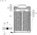
- FIG. 1 is a sectional view of a cylindrical secondary battery having a multilayer battery case according to a first preferred embodiment of the present invention.
- the cylindrical secondary battery having the multilayer battery case according to the first embodiment of the present invention includes an electrode assembly 100, a cap assembly 200, and a cylindrical battery case 300 configured to receive the same.
- a positive electrode tab 140 attached to the upper end of the electrode assembly 100 is electrically connected to the cap assembly 200, and a negative electrode tab 150 attached to the lower end of the electrode assembly 100 is connected to the bottom of the battery case 300.
- an insulating member may be located at the upper part of the electrode assembly 100, and the insulating member (not shown) serves to insulate the electrode assembly 100 and the cap assembly 200 from each other.
- the cap assembly 200 is located at the upper part of the insulating member (not shown) so as to be electrically connected to the positive electrode tab 130 attached to the upper end of the electrode assembly 100, and is coupled to the upper open end of the battery case 300 so as to seal the electrode assembly 100 received in the battery case 300.
- the cap assembly 200 is configured such that a current interrupt device 210, a current interrupt gasket 220, a safety vent 230, a PTC element 240, and a top cap 250 are sequentially stacked from below, and a crimping gasket 260 is located at the outer edges of the current interrupt device 210 and the top cap 250.
- the positive electrode tab 140 is connected to the current interrupt device 210 at a predetermined position of the lower surface thereof.
- the current interrupt device 210 is shown as being flat in the figure, the central part of the current interrupt device may be convex upwards.
- the safety vent 230 which is formed such that the central part of the safety vent protrudes downwards, is located at the upper part of the current interrupt device 210.
- the safety vent 230 interrupts current and discharges gas in the case in which the pressure in the battery increases, and is disposed such that one surface of the safety vent contacts the PTC element 240 and the end surface of the edge of the safety vent contacts the crimping gasket 260.
- PTC element 240 One surface of the edge of the positive temperature coefficient (PTC) element 240, the resistance of which increases to interrupt current when the temperature in the battery increases, abuts the safety vent 230, and the other surface the edge of the PTC element abuts the inner surface of the edge of the top cap 250.
- PTC positive temperature coefficient
- gas is generated in the battery due to various causes, such as external impact, whereby the pressure in the battery increases, and therefore the battery may catch fire or explode.
- the current interrupt device 210 and the safety vent 230 are provided in order to easily guide the discharge of gas acting as a cause of increasing the pressure in the battery, when the pressure in the battery reaches a predetermined pressure or higher, predetermined portions of the current interrupt device 210 and the safety vent 230 are broken to prevent explosion of the battery.
- the top cap 250 which is located at the uppermost part, seals the upper open end of the battery case 300, and forms a positive electrode terminal.
- a crimping process and a beading process are performed in order to fix the cap assembly 200.
- the crimping gasket 260 is attached to the edges, i.e. the outer circumferential surfaces, of the current interrupt device 210, the safety vent 230, the PTC element 240, and the top cap 250 in order to prevent the above unit components from being deformed or damaged at the time of performing the crimping process and the beading process and to improve tight contact between the current interrupt device 210 and the top cap 250.
- the material for the crimping gasket 260 is not particularly restricted as long as the material exhibits predetermined elasticity and durability, and may be, as an example, poly butylene terephthalate (PBT), polyphenylene sulfide (PPS), or perfluoroalkoxy (PFA).
- the battery case 300 receives the electrode assembly 100 and the cap assembly 200 therein, and the negative electrode tab 150 extends downwards and is then connected to the bottom of the battery case 300 such that the bottom of the main body of the battery case 300 acts as a negative electrode.
- the battery case 300 has a multilayer structure including an inner layer 310 and an outer layer 320. Specifically, the inner layer 310 is connected so as to directly contact the negative electrode tab 150, and the outer layer 320 is located outside the inner layer 310.
- the outer layer 320 is preferably made of a material that exhibits lower thermal conductivity than the inner layer 310.
- the inner layer 310 may be a sheet made of a copper material
- the outer layer 320 may be a nickel or nickel-plated steel sheet.
- a circular-band-shaped welding portion 330 is formed at the edge of the bottom surface of the battery case 300 in order to fix the inner layer 310 and the outer layer 320 to each other such that the layers are securely electrically connected to each other.
- the inner layer 310 and the outer layer 320 are adhered and fixed to each other via only the welding portion 330 formed by ultrasonic welding.
- the present invention has advantages in that, when the negative electrode tab 150 made of the copper material is adopted, the maximum allowable current and heat dissipation characteristics thereof are excellent, whereby it is possible to provide a high-output battery, the negative electrode tab 150 and the inner layer 310 have the same melting point, since the negative electrode tab 150 and the inner layer 310 are made of the same kind of metal, i.e. copper, whereby it is possible to easily fix the negative electrode tab 150 to the inner layer 310 by resistance welding, and it is not necessary to use a copper-nickel clad, which is expensive.
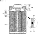
- FIG. 2 is a sectional view of a cylindrical secondary battery having a multilayer battery case according to a second preferred embodiment of the present invention.
- This embodiment is different from the first embodiment of FIG. 1 in connection with the position of the welding portion 330. That is, in the second embodiment, the welding portion 330 may be located at a predetermined region of the side surface of the battery case 300, rather than the edge of the bottom surface of the battery case.
- FIG. 3 is a sectional view of a cylindrical secondary battery having a multilayer battery case according to a third preferred embodiment of the present invention. This embodiment is different from the first embodiment of FIG. 1 in connection with the position of the welding portion 330. That is, in the third embodiment, the welding portion 330 may be located at a predetermined region of the upper surface of the battery case 300, rather than the edge of the bottom surface of the battery case.
- FIG. 4 is a sectional view of a cylindrical secondary battery having a multilayer battery case according to a fourth preferred embodiment of the present invention.
- the welding portion 330 is located at the edge of the bottom surface of the battery case in the first embodiment of FIG. 1 , the welding portion 330 may be further formed at a predetermined region of the upper surface of the battery case 300 in the fourth embodiment.
- welding portions 330 may be formed at the edge of the bottom surface of the battery case 300 and the side surface of the battery case, the side surface and the upper surface of the battery case 300, or the edge of the bottom surface of the battery case 300 and the side surface and the upper surface of the battery case.
- FIG. 5(B) is a view of the multilayer sheet when viewed from above, which is a view showing the position and shape of a welding portion 330 formed by ultrasonic joining. That is, when welding is performed while rotating the ultrasonic horn 420 or the stacked-layer sheet including the inner layer 310 and the outer layer 320, a circular-band-shaped welding portion 330 having a predetermined inner diameter is formed, whereby the inner layer 310 and the outer layer 320 are welded to each other.
- FIG. 6 is a conceptual view illustrating a method of welding a multilayer sheet for battery cases applied to the fourth embodiment of the present invention. Welding is performed using an ultrasonic horn 420 having four tips 421 spaced apart from each other by a predetermined distance (see FIG. 6(A) ), and when welding is performed while rotating the ultrasonic horn 420 or the stacked-layer sheet, it is possible to form two circular-band-shaped welding portions 330 having different inner diameters on the basis of an imaginary identical central point (see FIG. 6(B) ).
- FIG. 7 is a conceptual view illustrating a process of manufacturing the cylindrical secondary battery having the multilayer battery case according to the first preferred embodiment of the present invention.
- the method of manufacturing the cylindrical secondary battery according to the present invention includes a step of preparing a stacked-layer sheet, a step of welding only a predetermined region of the stacked-layer sheet, a step of deep-drawing the welded stacked-layer sheet to prepare a cylindrical battery case having an open upper part, a step of receiving an electrode assembly and a cap assembly in the cylindrical battery case, and a step of fixing the upper part of the cylindrical battery case.
- the stacked-layer sheet having a welding portion 330 formed thereat is placed at the upper part of a mold 510 having a predetermined inner diameter and height, the stacked-layer sheet is pressed using a punch 520 from above the stacked-layer sheet, i.e. the stacked-layer sheet is deep-drawn, in order to form the stacked-layer sheet such that the upper part of the stacked-layer sheet is open while the lower surface and the side surface of the stacked-layer sheet are bent at a predetermined angle.
- the welding potion 330 is located in the vertical surface of the mold 510 such that the welding potion 330 is located at the edge of the bottom surface of the cylindrical battery case. It is obvious that, in the case in which the battery case according to the second embodiment is formed, the welding portion 330 of the stacked-layer sheet must be larger than the bottom surface of the mold 510 and the welding portion 333 must be located so as to wrap the bottom surface of the mold 510.
- An electrode assembly 100 and a cap assembly 200 are sequentially received in the battery case prepared as described above through the upper end opening thereof, and then a jig 530 is pushed to perform a crimping process and a beading process.
- both a negative electrode tab and an inner layer of the battery case are made of the same kind of material, such as a copper material, whereby it is possible to secure reliability in welding and thus to contribute to a reduction in defect rate of products.
- both the negative electrode tab and the inner layer of the battery case are made of a copper material that exhibits excellent maximum allowable current and heat dissipation characteristics, whereby it is possible to improve heat diffusion and thus to provide a high-output secondary battery.
- a predetermined region of a multilayer sheet made of a copper material and a nickel material, which are different kinds of metals is ultrasonically welded so as to be used as a sheet for battery cases without using a copper-nickel clad, which is expensive, whereby it is possible to reduce manufacturing costs.
Landscapes
- Chemical & Material Sciences (AREA)
- Chemical Kinetics & Catalysis (AREA)
- Electrochemistry (AREA)
- General Chemical & Material Sciences (AREA)
- Engineering & Computer Science (AREA)
- Manufacturing & Machinery (AREA)
- Mechanical Engineering (AREA)
- Inorganic Chemistry (AREA)
- Sealing Battery Cases Or Jackets (AREA)
- Connection Of Batteries Or Terminals (AREA)
- Secondary Cells (AREA)
Abstract
Description
- This application claims the benefit of priority to Korean Patent Application No.
2019-0067867 filed on June 10, 2019 - The present invention relates to a cylindrical secondary battery having a multilayer battery case and a method of manufacturing the same, and more particularly to a cylindrical secondary battery having a multilayer battery case configured such that only a predetermined region of a sheet made of different kinds of metals including a copper material and a nickel material, is ultrasonically welded so as to be used as a sheet for battery cases and such that a negative electrode tab is made of copper, which is the same kind of metal as an inner layer of the battery case, whereby it is possible to secure reliability in welding and to provide a high-output secondary battery, and a method of manufacturing the same.
- As mobile devices have been continuously developed and the demand for mobile devices has increased, secondary batteries, which are capable of being charged and discharged, have been used as energy sources for various mobile devices. In addition, secondary batteries have also attracted considerable attention as energy sources for electric vehicles and hybrid electric vehicles, which have been presented as alternatives to existing gasoline and diesel vehicles using fossil fuels.
- Based on the shape of a battery case, secondary batteries are classified into a cylindrical battery having an electrode assembly mounted in a cylindrical metal can, a prismatic battery having an electrode assembly mounted in a prismatic metal can, and a pouch-shaped battery having an electrode assembly mounted in a pouch-shaped case made of an aluminum laminate sheet.
- The electrode assembly, which is mounted in the battery case, is a power generating element that is configured to have a structure including a positive electrode, a negative electrode, and a separator that is interposed between the positive electrode and the negative electrode and that can be charged and discharged. The electrode assembly is classified as a jelly-roll type electrode assembly, which is configured to have a structure in which a long sheet type positive electrode and a long sheet type negative electrode, to which active materials are applied, are wound in the state in which a separator is disposed between the positive electrode and the negative electrode, or a stacked type electrode assembly, which is configured to have a structure in which a plurality of positive electrodes having a predetermined size and a plurality of negative electrodes having a predetermined size are sequentially stacked in the state in which separators are disposed respectively between the positive electrodes and the negative electrodes. The jelly-roll type electrode assembly has advantages in that it is easy to manufacture the jelly-roll type electrode assembly and in that the jelly-roll type electrode assembly has high energy density per weight.
- Meanwhile, in such a secondary battery, a negative electrode tab extending from a negative electrode is welded to the lower surface of the inside of a battery case by resistance welding. Resistance welding is generally performed by inserting a first welding rod into a core of an electrode assembly so as to contact the negative electrode tab and applying current to a second welding rod in the state in which the second welding rod is in tight contact with the outer surface of the lower end of the battery case at a position opposite the first welding rod. In the case in which a plurality of conductors contacts each other, heat is generated due to contact resistance, and welding is performed by the heat. A larger amount of heat is generated at the contact portion as contact resistance increases. Contact resistance increases as the contact area between the conductors decreases. The inner surface of the lower end of a battery case of a general cylindrical secondary battery and a negative electrode tab of the secondary battery are smooth and flat, whereby contact resistance is low, and therefore weldability is reduced.
- In connection therewith, Patent Document 1 discloses a cylindrical secondary battery configured such that a projecting portion is formed on a lower surface plate of a battery case in order to increase contact resistance when a negative electrode tab comes into contact with the battery case, whereby it is possible to easily weld the negative electrode tab, but has a shortcoming in that the negative electrode tab is deformed by the projecting portion located at the fused surface between the lower surface plate of the battery case and the negative electrode tab, whereby a ripple phenomenon may occur.
- In addition, although the negative electrode tab is formed so as to have an embossed structure in order to weld the negative electrode tab, which is made of a metal having low resistance, whereby welding processability is improved, the amount of heat generated when the negative electrode tab made of the low-resistance material is welded to the battery case, which has relatively high resistance, is considerably small, whereby it is not possible to secure processability to a preferred level, and a plurality of secondary batteries having welding defects may be manufactured.
- Patent Document 2 discloses a secondary battery including a clad negative electrode tab having a two-layer structure including nickel and copper. Since the clad negative electrode tab having the two-layer structure including nickel and copper has higher resistance than a negative electrode tab made of a copper material, however, the maximum allowable current and heat dissipation characteristics of the clad negative electrode tab are deteriorated, whereby it is not possible to provide a high-output secondary battery.
-
- (Patent Document 1) Korean Patent Application Publication No.
2007-0082969 - (Patent Document 2) Korean Patent Application Publication No.
2009-0132494 - The present invention has been made in view of the above problems, and it is an object of the present invention to provide a cylindrical secondary battery having excellent allowable current and heat dissipation characteristics, whereby the output of the cylindrical secondary battery may be increased, and a method of manufacturing the same.
- It is another object of the present invention to provide a cylindrical secondary battery that does not use an expensive material, such as a copper-nickel clad, whereby production cost of the cylindrical secondary battery may be reduced, and a method of manufacturing the same.
- It is a further object of the present invention to provide a cylindrical secondary battery that uses a negative electrode tab and a battery case made of the same kind of metal, whereby resistance welding may be easily performed and the defect rate of products may be reduced, and a method of manufacturing the same.
- A cylindrical secondary battery having a multilayer battery case according to the present invention provided to solve the above problems includes an
electrode assembly 100 including apositive electrode 110, anegative electrode 120, aseparator 130 interposed between thepositive electrode 110 and thenegative electrode 120, apositive electrode tab 140 having one side connected to thepositive electrode 110, and anegative electrode tab 150 having one side connected to thenegative electrode 120; acap assembly 200 including acurrent interrupt device 210 configured to interrupt current when pressure in the battery increases, the current interrupt device being located at the upper part of theelectrode assembly 100, asafety vent 230 connected to the upper end of thecurrent interrupt device 210, and atop cap 250 formed in an upwardly protruding shape, the lower surface of the outer circumferential surface of the top cap being in contact with the upper surface of the outer circumferential surface of thesafety vent 230; and acylindrical battery case 300 configured to receive theelectrode assembly 100 and thecap assembly 200 therein, wherein thecylindrical battery case 300 includes aninner layer 310 disposed adjacent to theelectrode assembly 100 and anouter layer 320 made of a material that exhibits lower thermal conductivity than theinner layer 310, theinner layer 310 and theouter layer 320 being provided with awelding portion 330, at which only predetermined regions of the inner layer and the outer layer are fixed by welding. - Also, in the cylindrical secondary battery having the multilayer battery case according to the present invention, the
inner layer 310 may be made of copper, and theouter layer 320 may be a nickel or nickel-plated steel sheet. - Also, in the cylindrical secondary battery having the multilayer battery case according to the present invention, the
welding portion 330 may be formed by ultrasonic welding. - Also, in the cylindrical secondary battery having the multilayer battery case according to the present invention, the
welding portion 330 may be located at the lower surface of thebattery case 300. - Also, in the cylindrical secondary battery having the multilayer battery case according to the present invention, the
welding portion 330 may be formed in a circular band shape smaller than the inner diameter of thebattery case 300. - Also, in the cylindrical secondary battery having the multilayer battery case according to the present invention, the
welding portion 330 may be located at the side surface of thebattery case 300. - Also, in the cylindrical secondary battery having the multilayer battery case according to the present invention, the
welding portion 330 may be located at the upper surface of thebattery case 300. - Also, in the cylindrical secondary battery having the multilayer battery case according to the present invention, the
welding portion 330 may be located at two or more of the lower surface, the side surface, and the upper surface of thebattery case 300. - A method of manufacturing a cylindrical secondary battery having a multilayer battery case according to the present invention includes a step of overlapping a copper sheet and a nickel or nickel-plated steel sheet to prepare a stacked-layer sheet; a step of welding only a predetermined region of the stacked-layer sheet to form a welding portion; a step of deep-drawing the stacked-layer sheet to prepare a cylindrical battery case configured such that the lower surface and the side surface of the cylindrical battery case are bent at a predetermined angle and such that the upper part of the cylindrical battery case is open; a step of receiving an electrode assembly and a cap assembly in the cylindrical battery case; and a step of fixing the upper part of the cylindrical battery case.
- Also, in the method of manufacturing the cylindrical secondary battery having the multilayer battery case according to the present invention, the welding may be ultrasonic welding.
- Also, in the method of manufacturing the cylindrical secondary battery having the multilayer battery case according to the present invention, the
welding portion 330 may be formed so as to have the shape of a circular band. - Also, in the method of manufacturing the cylindrical secondary battery having the multilayer battery case according to the present invention, the circular band may include two or more circular bands having different inner diameters on the basis of an imaginary identical central point.
-
-
FIG. 1 is a sectional view of a cylindrical secondary battery having a multilayer battery case according to a first preferred embodiment of the present invention. -
FIG. 2 is a sectional view of a cylindrical secondary battery having a multilayer battery case according to a second preferred embodiment of the present invention. -
FIG. 3 is a sectional view of a cylindrical secondary battery having a multilayer battery case according to a third preferred embodiment of the present invention. -
FIG. 4 is a sectional view of a cylindrical secondary battery having a multilayer battery case according to a fourth preferred embodiment of the present invention. -
FIG. 5 is a conceptual view illustrating a method of welding a multilayer sheet for battery cases applied to the first embodiment of the present invention. -
FIG. 6 is a conceptual view illustrating a method of welding a multilayer sheet for battery cases applied to the fourth embodiment of the present invention. -
FIG. 7 is a conceptual view illustrating a process of manufacturing the cylindrical secondary battery having the multilayer battery case according to the first preferred embodiment of the present invention. - In the present application, it should be understood that the terms "comprises," "has," or "includes," etc. specify the presence of features, integers, steps, operations, components, parts, or combinations thereof described in the specification, but do not preclude the presence or addition of one or more other features, integers, steps, operations, components, parts, or combinations thereof.
- In addition, the same reference numerals will be used throughout the drawings to refer to parts that perform similar functions or operations. In the case in which one part is said to be connected to another part in the specification, not only may the one part be directly connected to the other part, but also, the one part may be indirectly connected to the other part via a further part. In addition, that a certain element is included does not mean that other elements are excluded, but means that the other elements may be further included unless mentioned otherwise.
- Hereinafter, a cylindrical secondary battery having a multilayer battery case according to the present invention and a method of manufacturing the same will be described with reference to the accompanying drawings.
-
FIG. 1 is a sectional view of a cylindrical secondary battery having a multilayer battery case according to a first preferred embodiment of the present invention. - Referring to
FIG. 1 , the cylindrical secondary battery having the multilayer battery case according to the first embodiment of the present invention includes anelectrode assembly 100, acap assembly 200, and acylindrical battery case 300 configured to receive the same. - The
electrode assembly 100 may be a jelly-roll type electrode assembly configured to have a structure in which a long-sheet typepositive electrode 110 and a long-sheet typenegative electrode 120 are wound in the state in which aseparator 130 is interposed therebetween, a stacked type electrode assembly including unit cells, each of which is configured to have a structure in which a rectangularpositive electrode 110 and a rectangularnegative electrode 120 are stacked in the state in which aseparator 130 is interposed therebetween, a stacked and folded type electrode assembly configured to have a structure in which the unit cells are wound using a long separation film, or a laminated and stacked type electrode assembly configured to have a structure in which the unit cells are stacked in the state in which a separator is interposed therebetween and are then attached to each other. - A
positive electrode tab 140 attached to the upper end of theelectrode assembly 100 is electrically connected to thecap assembly 200, and anegative electrode tab 150 attached to the lower end of theelectrode assembly 100 is connected to the bottom of thebattery case 300. - Here, the
negative electrode tab 150 is preferably made of a copper material that has low resistance and high maximum allowable current. - Meanwhile, an insulating member (not shown) may be located at the upper part of the
electrode assembly 100, and the insulating member (not shown) serves to insulate theelectrode assembly 100 and thecap assembly 200 from each other. - The
cap assembly 200 is located at the upper part of the insulating member (not shown) so as to be electrically connected to thepositive electrode tab 130 attached to the upper end of theelectrode assembly 100, and is coupled to the upper open end of thebattery case 300 so as to seal theelectrode assembly 100 received in thebattery case 300. - Specifically, the
cap assembly 200 is configured such that a currentinterrupt device 210, a currentinterrupt gasket 220, asafety vent 230, aPTC element 240, and atop cap 250 are sequentially stacked from below, and a crimpinggasket 260 is located at the outer edges of thecurrent interrupt device 210 and thetop cap 250. - The
positive electrode tab 140 is connected to thecurrent interrupt device 210 at a predetermined position of the lower surface thereof. Although thecurrent interrupt device 210 is shown as being flat in the figure, the central part of the current interrupt device may be convex upwards. - The
safety vent 230, which is formed such that the central part of the safety vent protrudes downwards, is located at the upper part of thecurrent interrupt device 210. Thesafety vent 230 interrupts current and discharges gas in the case in which the pressure in the battery increases, and is disposed such that one surface of the safety vent contacts thePTC element 240 and the end surface of the edge of the safety vent contacts the crimpinggasket 260. - The current interrupt
gasket 220 is located such that the state in which the current interruptdevice 210 and thesafety vent 230 are electrically insulated from each other can be maintained, except for downwardly protruding portions of the current interruptdevice 210 and thesafety vent 230. - One surface of the edge of the positive temperature coefficient (PTC)
element 240, the resistance of which increases to interrupt current when the temperature in the battery increases, abuts thesafety vent 230, and the other surface the edge of the PTC element abuts the inner surface of the edge of thetop cap 250. - For a cylindrical secondary battery, gas is generated in the battery due to various causes, such as external impact, whereby the pressure in the battery increases, and therefore the battery may catch fire or explode.
- The current interrupt
device 210 and thesafety vent 230 are provided in order to easily guide the discharge of gas acting as a cause of increasing the pressure in the battery, when the pressure in the battery reaches a predetermined pressure or higher, predetermined portions of the current interruptdevice 210 and thesafety vent 230 are broken to prevent explosion of the battery. - The
top cap 250, which is located at the uppermost part, seals the upper open end of thebattery case 300, and forms a positive electrode terminal. - In a general cylindrical secondary battery, a crimping process and a beading process are performed in order to fix the
cap assembly 200. - The crimping
gasket 260 is attached to the edges, i.e. the outer circumferential surfaces, of the current interruptdevice 210, thesafety vent 230, thePTC element 240, and thetop cap 250 in order to prevent the above unit components from being deformed or damaged at the time of performing the crimping process and the beading process and to improve tight contact between the current interruptdevice 210 and thetop cap 250. Here, the material for the crimpinggasket 260 is not particularly restricted as long as the material exhibits predetermined elasticity and durability, and may be, as an example, poly butylene terephthalate (PBT), polyphenylene sulfide (PPS), or perfluoroalkoxy (PFA). - The
battery case 300 receives theelectrode assembly 100 and thecap assembly 200 therein, and thenegative electrode tab 150 extends downwards and is then connected to the bottom of thebattery case 300 such that the bottom of the main body of thebattery case 300 acts as a negative electrode. - Here, the
battery case 300 has a multilayer structure including aninner layer 310 and anouter layer 320. Specifically, theinner layer 310 is connected so as to directly contact thenegative electrode tab 150, and theouter layer 320 is located outside theinner layer 310. - The
outer layer 320 is preferably made of a material that exhibits lower thermal conductivity than theinner layer 310. As an example, theinner layer 310 may be a sheet made of a copper material, and theouter layer 320 may be a nickel or nickel-plated steel sheet. - A circular-band-shaped
welding portion 330 is formed at the edge of the bottom surface of thebattery case 300 in order to fix theinner layer 310 and theouter layer 320 to each other such that the layers are securely electrically connected to each other. - That is, in the
battery case 300 according to the first embodiment of the present invention, theinner layer 310 and theouter layer 320 are adhered and fixed to each other via only thewelding portion 330 formed by ultrasonic welding. - Therefore, the present invention has advantages in that, when the
negative electrode tab 150 made of the copper material is adopted, the maximum allowable current and heat dissipation characteristics thereof are excellent, whereby it is possible to provide a high-output battery, thenegative electrode tab 150 and theinner layer 310 have the same melting point, since thenegative electrode tab 150 and theinner layer 310 are made of the same kind of metal, i.e. copper, whereby it is possible to easily fix thenegative electrode tab 150 to theinner layer 310 by resistance welding, and it is not necessary to use a copper-nickel clad, which is expensive. -
FIG. 2 is a sectional view of a cylindrical secondary battery having a multilayer battery case according to a second preferred embodiment of the present invention. This embodiment is different from the first embodiment ofFIG. 1 in connection with the position of thewelding portion 330. That is, in the second embodiment, thewelding portion 330 may be located at a predetermined region of the side surface of thebattery case 300, rather than the edge of the bottom surface of the battery case. -
FIG. 3 is a sectional view of a cylindrical secondary battery having a multilayer battery case according to a third preferred embodiment of the present invention. This embodiment is different from the first embodiment ofFIG. 1 in connection with the position of thewelding portion 330. That is, in the third embodiment, thewelding portion 330 may be located at a predetermined region of the upper surface of thebattery case 300, rather than the edge of the bottom surface of the battery case. -
FIG. 4 is a sectional view of a cylindrical secondary battery having a multilayer battery case according to a fourth preferred embodiment of the present invention. Although thewelding portion 330 is located at the edge of the bottom surface of the battery case in the first embodiment ofFIG. 1 , thewelding portion 330 may be further formed at a predetermined region of the upper surface of thebattery case 300 in the fourth embodiment. - Of course, although not shown in the figures,
welding portions 330 may be formed at the edge of the bottom surface of thebattery case 300 and the side surface of the battery case, the side surface and the upper surface of thebattery case 300, or the edge of the bottom surface of thebattery case 300 and the side surface and the upper surface of the battery case. - Next, a method of welding a multilayer sheet for battery cases will be described with reference to
FIGS. 5 and6 . -
FIG. 5 is a conceptual view illustrating a method of welding a multilayer sheet for battery cases applied to the first embodiment of the present invention, whereinFIG. 5(A) is a sectional view showing the state in which a multilayer sheet is seated in an ultrasonic welding apparatus. Specifically, aninner layer 310 and anouter layer 320 each having a predetermined width and length are placed above adie 410 in an overlapping state, and anultrasonic horn 420 is located thereabove. - When an ultrasonic wave having a predetermined range is applied through
tips 421 together with pressing, the temperature of corresponding regions of theinner layer 310 and theouter layer 320 is increased by vibration-based frictional heat, whereby the regions of the inner layer and the outer layer are joined to each other. Such an ultrasonic welding principle is well known, and therefore a detailed description thereof will be omitted. -
FIG. 5(B) is a view of the multilayer sheet when viewed from above, which is a view showing the position and shape of awelding portion 330 formed by ultrasonic joining. That is, when welding is performed while rotating theultrasonic horn 420 or the stacked-layer sheet including theinner layer 310 and theouter layer 320, a circular-band-shapedwelding portion 330 having a predetermined inner diameter is formed, whereby theinner layer 310 and theouter layer 320 are welded to each other. -
FIG. 6 is a conceptual view illustrating a method of welding a multilayer sheet for battery cases applied to the fourth embodiment of the present invention. Welding is performed using anultrasonic horn 420 having fourtips 421 spaced apart from each other by a predetermined distance (seeFIG. 6(A) ), and when welding is performed while rotating theultrasonic horn 420 or the stacked-layer sheet, it is possible to form two circular-band-shapedwelding portions 330 having different inner diameters on the basis of an imaginary identical central point (seeFIG. 6(B) ). - Of course, it is possible to form a plurality of welding portions having predetermined shapes using an
ultrasonic horn 420 having asingle tip 421 while rotating the stacked-layer sheet or theultrasonic horn 420, and it is also possible to form awelding portion 330 having any of various shapes, rather than a circular band shape. - Subsequently, a method of manufacturing a cylindrical secondary battery having a multilayer battery case according to the present invention will be described.
FIG. 7 is a conceptual view illustrating a process of manufacturing the cylindrical secondary battery having the multilayer battery case according to the first preferred embodiment of the present invention. - The method of manufacturing the cylindrical secondary battery according to the present invention includes a step of preparing a stacked-layer sheet, a step of welding only a predetermined region of the stacked-layer sheet, a step of deep-drawing the welded stacked-layer sheet to prepare a cylindrical battery case having an open upper part, a step of receiving an electrode assembly and a cap assembly in the cylindrical battery case, and a step of fixing the upper part of the cylindrical battery case.
- The steps of preparing a stacked-layer sheet and welding only a predetermined region of the stacked-layer sheet have been described with reference to
FIG. 5 , and therefore a further description thereof will be omitted. - In the step of preparing a cylindrical battery case, the stacked-layer sheet having a
welding portion 330 formed thereat is placed at the upper part of amold 510 having a predetermined inner diameter and height, the stacked-layer sheet is pressed using apunch 520 from above the stacked-layer sheet, i.e. the stacked-layer sheet is deep-drawn, in order to form the stacked-layer sheet such that the upper part of the stacked-layer sheet is open while the lower surface and the side surface of the stacked-layer sheet are bent at a predetermined angle. - Here, the
welding potion 330 is located in the vertical surface of themold 510 such that thewelding potion 330 is located at the edge of the bottom surface of the cylindrical battery case. It is obvious that, in the case in which the battery case according to the second embodiment is formed, thewelding portion 330 of the stacked-layer sheet must be larger than the bottom surface of themold 510 and the welding portion 333 must be located so as to wrap the bottom surface of themold 510. - An
electrode assembly 100 and acap assembly 200 are sequentially received in the battery case prepared as described above through the upper end opening thereof, and then ajig 530 is pushed to perform a crimping process and a beading process. - Of course, it is reasonable to further perform a resistance welding process in order to connect a
negative electrode tab 140 made of a copper material to aninner layer 310 of thebattery case 300 made of the same material. - Although the specific details of the present invention have been described in detail, those skilled in the art will appreciate that the detailed description thereof discloses only preferred embodiments of the present invention and thus does not limit the scope of the present invention. Accordingly, those skilled in the art will appreciate that various changes and modifications are possible, without departing from the category and the technical idea of the present invention, and it will be obvious that such changes and modifications fall within the scope of the appended claims.
-
- 100: Electrode assembly
- 110: Positive electrode 120: Negative electrode
- 130: Separator 140: Positive electrode tab
- 150: Negative electrode tab
- 200: Cap assembly
- 210: Current interrupt device 220: Current interrupt gasket
- 230: Safety vent 240: PTC element
- 250: Top cap 260: Crimping gasket
- 300: Battery case
- 310: Inner layer 320: Outer layer
- 330: Welding portion
- 410: Die 420: Ultrasonic horn
- 421: Tip
- 510: Mold 520: Punch
- 530: Jig
- In a cylindrical secondary battery having a multilayer battery case according to the present invention, both a negative electrode tab and an inner layer of the battery case are made of the same kind of material, such as a copper material, whereby it is possible to secure reliability in welding and thus to contribute to a reduction in defect rate of products.
- Also, in the cylindrical secondary battery having the multilayer battery case according to the present invention, both the negative electrode tab and the inner layer of the battery case are made of a copper material that exhibits excellent maximum allowable current and heat dissipation characteristics, whereby it is possible to improve heat diffusion and thus to provide a high-output secondary battery.
- Furthermore, in the cylindrical secondary battery having the multilayer battery case according to the present invention, only a predetermined region of a multilayer sheet made of a copper material and a nickel material, which are different kinds of metals, is ultrasonically welded so as to be used as a sheet for battery cases without using a copper-nickel clad, which is expensive, whereby it is possible to reduce manufacturing costs.
Claims (12)
- A cylindrical secondary battery having a multilayer battery case, the cylindrical secondary battery comprising:an electrode assembly comprising a positive electrode, a negative electrode, a separator interposed between the positive electrode and the negative electrode, a positive electrode tab having one side connected to the positive electrode, and a negative electrode tab having one side connected to the negative electrode;a cap assembly comprising a current interrupt device configured to interrupt current when pressure in the battery increases, the current interrupt device being located at an upper part of the electrode assembly, a safety vent connected to an upper end of the current interrupt device, and a top cap formed in an upwardly protruding shape, a lower surface of an outer circumferential surface of the top cap being in contact with an upper surface of an outer circumferential surface of the safety vent; anda cylindrical battery case configured to receive the electrode assembly and the cap assembly therein, whereinthe cylindrical battery case comprises an inner layer disposed adjacent to the electrode assembly and an outer layer made of a material that exhibits lower thermal conductivity than the inner layer, the inner layer and the outer layer being provided with a welding portion, at which only the predetermined regions of the inner layer and the outer layer are fixed by welding.
- The cylindrical secondary battery according to claim 1, wherein the inner layer is made of copper, and the outer layer is a nickel or nickel-plated steel sheet.
- The cylindrical secondary battery according to claim 1, wherein the welding portion is formed by ultrasonic welding.
- The cylindrical secondary battery according to claim 3, wherein the welding portion is located at a lower surface of the battery case.
- The cylindrical secondary battery according to claim 4, wherein the welding portion is formed in a circular band shape smaller than an inner diameter of the battery case.
- The cylindrical secondary battery according to claim 3, wherein the welding portion is located at a side surface of the battery case.
- The cylindrical secondary battery according to claim 3, wherein the welding portion is located at an upper surface of the battery case.
- The cylindrical secondary battery according to claim 3, wherein the welding portion is located at two or more of a lower surface, a side surface, and an upper surface of the battery case.
- A method of manufacturing a cylindrical secondary battery having a multilayer battery case, the method comprising:overlapping a copper sheet and a nickel or nickel-plated steel sheet to prepare a stacked-layer sheet;welding only a predetermined region of the stacked-layer sheet to form a welding portion;deep-drawing the stacked-layer sheet to prepare a cylindrical battery case configured such that a lower surface and a side surface of the cylindrical battery case are bent at a predetermined angle and such that an upper part of the cylindrical battery case is open;receiving an electrode assembly and a cap assembly in the cylindrical battery case; andfixing the upper part of the cylindrical battery case.
- The method according to claim 9, wherein the welding is ultrasonic welding.
- The method according to claim 9, wherein the welding portion is formed so as to have a shape of a circular band.
- The method according to claim 11, wherein the circular band comprises two or more circular bands having different inner diameters on a basis of an imaginary identical central point.
Applications Claiming Priority (2)
| Application Number | Priority Date | Filing Date | Title |
|---|---|---|---|
| KR1020190067867A KR102522106B1 (en) | 2019-06-10 | 2019-06-10 | Cylindrical Secondary Battery with Multilayered Battery Case And Method of Manufacturing The Same |
| PCT/KR2020/002215 WO2020251134A1 (en) | 2019-06-10 | 2020-02-17 | Cylindrical secondary battery having multilayer-structured battery case, and method for manufacturing same |
Publications (2)
| Publication Number | Publication Date |
|---|---|
| EP3780134A1 true EP3780134A1 (en) | 2021-02-17 |
| EP3780134A4 EP3780134A4 (en) | 2021-07-21 |
Family
ID=73781842
Family Applications (1)
| Application Number | Title | Priority Date | Filing Date |
|---|---|---|---|
| EP20786428.1A Pending EP3780134A4 (en) | 2019-06-10 | 2020-02-17 | SECONDARY CYLINDRICAL BATTERY HAVING A MULTI-LAYER STRUCTURED BATTERY BOX AND ITS MANUFACTURING PROCESS |
Country Status (7)
| Country | Link |
|---|---|
| US (1) | US11735790B2 (en) |
| EP (1) | EP3780134A4 (en) |
| JP (1) | JP7048859B2 (en) |
| KR (1) | KR102522106B1 (en) |
| CN (1) | CN112449733B (en) |
| TW (1) | TWI845658B (en) |
| WO (1) | WO2020251134A1 (en) |
Families Citing this family (13)
| Publication number | Priority date | Publication date | Assignee | Title |
|---|---|---|---|---|
| CN121863017A (en) | 2021-02-19 | 2026-04-14 | 株式会社Lg新能源 | Riveting structure for electrode terminals and secondary batteries, battery packs and automobiles including them. |
| CN221687647U (en) * | 2021-06-28 | 2024-09-10 | 合肥国轩高科动力能源有限公司 | Cylindrical battery cell and battery |
| WO2023279230A1 (en) * | 2021-07-05 | 2023-01-12 | Hefei Gotion High-Tech Power Energy Co., Ltd. | Cylindrical battery cell, battery and method for forming cylindrical battery cell |
| KR102878356B1 (en) * | 2021-11-15 | 2025-10-29 | 주식회사 엘지에너지솔루션 | Cylindrical Battery Cell Having Improved Safety and Manufacturing Method Thereof |
| CN114937855B (en) * | 2022-03-30 | 2024-05-14 | 江苏正力新能电池技术有限公司 | Preparation method of cylindrical battery and cylindrical battery |
| CN114833443B (en) * | 2022-04-12 | 2024-09-17 | 海目星激光科技集团股份有限公司 | Welding method for multilayer tab |
| CN116000447B (en) * | 2022-04-21 | 2024-08-27 | 苏州朗旭新能源科技有限公司 | Continuous piece welding machine of electric core |
| JP2024123722A (en) * | 2023-03-01 | 2024-09-12 | プライムプラネットエナジー&ソリューションズ株式会社 | Secondary battery and battery module |
| CN116454550A (en) * | 2023-06-16 | 2023-07-18 | 深圳海辰储能控制技术有限公司 | A current collecting component and its preparation method, battery and electrical equipment |
| CN117697253A (en) * | 2024-01-04 | 2024-03-15 | 东莞市合鼎盛自动化设备有限公司 | Explosion-proof disc welding equipment |
| KR20250158155A (en) | 2024-04-29 | 2025-11-06 | 동원시스템즈 주식회사 | Riveting coupling structure between electrode terminal and gasket, cylindrical secondary battery having the riveting coupling structure, secondary battery pack having the cylindrical secondary battery, and riveting method of electrode terminal for improving assembly dimension dispersion error |
| KR20250176597A (en) | 2024-06-12 | 2025-12-22 | 동원시스템즈 주식회사 | Gasket injection molding mold device of a battery can, gasket injection molding method of the battery can, gasket manufactured by the injection molding method, cylindrical secondary battery including the gasket, and secondary battery pack with the cylindrical secondary battery |
| KR20250176596A (en) | 2024-06-12 | 2025-12-22 | 동원시스템즈 주식회사 | Gasket injection molding mold device of a battery can, gasket injection molding method of the battery can, gasket manufactured by the injection molding method, cylindrical secondary battery including the gasket, and secondary battery pack with the cylindrical secondary battery |
Family Cites Families (28)
| Publication number | Priority date | Publication date | Assignee | Title |
|---|---|---|---|---|
| JP3066338B2 (en) * | 1996-03-27 | 2000-07-17 | 三洋電機株式会社 | Battery |
| JP3349495B2 (en) * | 1996-03-27 | 2002-11-25 | 三洋電機株式会社 | Battery manufacturing method |
| US6447947B1 (en) * | 1999-12-13 | 2002-09-10 | The Gillette Company | Zinc/air cell |
| JP2001283796A (en) * | 2000-04-04 | 2001-10-12 | Matsushita Electric Ind Co Ltd | Lithium secondary battery and method of manufacturing the same |
| JP2003007260A (en) * | 2001-06-19 | 2003-01-10 | Mitsubishi Alum Co Ltd | Aluminum alloy plate for secondary battery case |
| KR100467698B1 (en) * | 2002-09-05 | 2005-01-24 | 삼성에스디아이 주식회사 | Cylindrical type lithium secondary battery and the fabrication method of the same |
| KR100502338B1 (en) * | 2002-12-27 | 2005-07-20 | 삼성에스디아이 주식회사 | Secondary battery |
| JP4184927B2 (en) * | 2002-12-27 | 2008-11-19 | 三星エスディアイ株式会社 | Secondary battery and manufacturing method thereof |
| JP4284541B2 (en) * | 2004-12-14 | 2009-06-24 | ソニー株式会社 | Secondary battery |
| JP3742422B1 (en) | 2005-03-17 | 2006-02-01 | 日立マクセル株式会社 | Flat battery |
| KR100778983B1 (en) | 2006-02-20 | 2007-11-22 | 삼성에스디아이 주식회사 | Can for cylindrical lithium secondary battery and cylindrical lithium secondary battery using same |
| JP5004488B2 (en) | 2006-03-31 | 2012-08-22 | 三洋電機株式会社 | battery |
| KR101297540B1 (en) * | 2006-09-29 | 2013-08-14 | 쉔젠 비에이케이 배터리 컴퍼니 리미티드 | Battery case and battery |
| US20090317707A1 (en) | 2008-06-20 | 2009-12-24 | Seungyeob Cha | Lithium secondary battery |
| CN201498534U (en) * | 2009-09-30 | 2010-06-02 | 广州市云通磁电有限公司 | Cylindrical battery case |
| KR101310731B1 (en) * | 2010-03-22 | 2013-09-24 | 주식회사 엘지화학 | Secondary battery |
| JP2012028490A (en) * | 2010-07-22 | 2012-02-09 | Taiyo Yuden Co Ltd | Electrochemical device |
| WO2012121468A1 (en) * | 2011-03-10 | 2012-09-13 | 신흥에스이씨주식회사 | Secondary battery having cap assembly with which components are bonded |
| JP6124399B2 (en) | 2013-02-26 | 2017-05-10 | セイコーインスツル株式会社 | Nonaqueous electrolyte secondary battery |
| KR101861888B1 (en) | 2014-05-13 | 2018-05-28 | 주식회사 엘지화학 | Case for Secondary Battery with High Formability and Method of Manufacturing the Same |
| JP2016033903A (en) * | 2014-07-31 | 2016-03-10 | ソニー株式会社 | Positive electrode active material, positive electrode and battery |
| CN206353577U (en) * | 2016-12-14 | 2017-07-25 | 东山电池工业(中国)有限公司 | A cylindrical battery structure |
| SE540378C2 (en) | 2016-12-21 | 2018-08-28 | Scania Cv Ab | An arrangement for mounting a boil-off pipe of a liquefied gas fuel system to a vehicle |
| KR102041131B1 (en) * | 2017-04-27 | 2019-11-07 | 주식회사 엘지화학 | Cylindrical Battery Cell Having Can of Dissimilar Metals |
| KR102486134B1 (en) | 2017-05-22 | 2023-01-10 | 주식회사 엘지에너지솔루션 | Cylindrical-type Battery Comprising Gasket- Washer for High-effective Sealing |
| CN108987614B (en) * | 2017-05-31 | 2022-02-08 | 深圳市比亚迪锂电池有限公司 | Battery shell and battery |
| DE102017211112A1 (en) | 2017-06-30 | 2019-01-03 | Robert Bosch Gmbh | battery cell |
| CN108070761A (en) * | 2017-12-26 | 2018-05-25 | 广州宇智科技有限公司 | Possess the single-phase α magnesium lithium alloys of excellent casting character and heat transfer property |
-
2019
- 2019-06-10 KR KR1020190067867A patent/KR102522106B1/en active Active
-
2020
- 2020-02-17 JP JP2020547147A patent/JP7048859B2/en active Active
- 2020-02-17 CN CN202080002282.2A patent/CN112449733B/en active Active
- 2020-02-17 WO PCT/KR2020/002215 patent/WO2020251134A1/en not_active Ceased
- 2020-02-17 US US17/058,902 patent/US11735790B2/en active Active
- 2020-02-17 EP EP20786428.1A patent/EP3780134A4/en active Pending
- 2020-04-21 TW TW109113227A patent/TWI845658B/en active
Also Published As
| Publication number | Publication date |
|---|---|
| TW202046530A (en) | 2020-12-16 |
| JP7048859B2 (en) | 2022-04-06 |
| US20210265687A1 (en) | 2021-08-26 |
| US11735790B2 (en) | 2023-08-22 |
| JP2021531611A (en) | 2021-11-18 |
| KR102522106B1 (en) | 2023-04-14 |
| WO2020251134A1 (en) | 2020-12-17 |
| TWI845658B (en) | 2024-06-21 |
| EP3780134A4 (en) | 2021-07-21 |
| CN112449733A (en) | 2021-03-05 |
| KR20200141200A (en) | 2020-12-18 |
| CN112449733B (en) | 2023-12-26 |
Similar Documents
| Publication | Publication Date | Title |
|---|---|---|
| US11735790B2 (en) | Secondary battery having multilayer battery case and method of manufacturing the same | |
| JP7607214B2 (en) | Power storage device | |
| KR102659830B1 (en) | Secondary battery And Fabricating Method Thereof | |
| US20220045391A1 (en) | Secondary battery and method of manufacturing the same | |
| CN101593818B (en) | Cap assembly and secondary battery having the same | |
| KR102462857B1 (en) | Cylindrical Battery Having no Beading Part and Method For Manufacturing Thereof | |
| EP2200116B1 (en) | Rechargeable battery | |
| KR102489229B1 (en) | Cylindrical Battery Having no Beading Part and Method For Manufacturing Thereof | |
| CN116034516A (en) | Cylindrical battery unit, battery pack and vehicle including same | |
| US8679673B2 (en) | Cap assembly, can, and secondary battery employing the same | |
| CN112368878B (en) | Secondary battery | |
| US20090098445A1 (en) | Cap assembly, secondary battery having the same, methods of manufacturing cap assembly and secondary battery | |
| US20220294089A1 (en) | Terminal component and electricity storage device | |
| JPWO2017119421A1 (en) | Electricity storage element | |
| KR102510891B1 (en) | Secondary battery | |
| JP6778641B2 (en) | Polygonal secondary battery | |
| JP7213213B2 (en) | Battery cell and manufacturing method thereof | |
| JP2025526493A (en) | Battery cells, battery modules, battery packs and automobiles including the same | |
| KR20240105183A (en) | Battery cell, module, Battery pack and Vehicle comprising same | |
| KR20130034284A (en) | Current interrupting device and secondary battery using the same | |
| KR102833974B1 (en) | Battery cell for preventing side wall of battery can from rupturing | |
| US20260100457A1 (en) | Battery Cell, and Battery Pack and Vehicle Including the Same | |
| EP4675782A1 (en) | Battery cell and method for manufacturing same | |
| KR20260043570A (en) | Can lid, Battery cell, Battery pack and Vehicle including the same | |
| KR20260039329A (en) | Battery and battery pack and vehicle including the same |
Legal Events
| Date | Code | Title | Description |
|---|---|---|---|
| STAA | Information on the status of an ep patent application or granted ep patent |
Free format text: STATUS: UNKNOWN |
|
| STAA | Information on the status of an ep patent application or granted ep patent |
Free format text: STATUS: THE INTERNATIONAL PUBLICATION HAS BEEN MADE |
|
| PUAI | Public reference made under article 153(3) epc to a published international application that has entered the european phase |
Free format text: ORIGINAL CODE: 0009012 |
|
| STAA | Information on the status of an ep patent application or granted ep patent |
Free format text: STATUS: REQUEST FOR EXAMINATION WAS MADE |
|
| 17P | Request for examination filed |
Effective date: 20201016 |
|
| AK | Designated contracting states |
Kind code of ref document: A1 Designated state(s): AL AT BE BG CH CY CZ DE DK EE ES FI FR GB GR HR HU IE IS IT LI LT LU LV MC MK MT NL NO PL PT RO RS SE SI SK SM TR |
|
| AX | Request for extension of the european patent |
Extension state: BA ME |
|
| A4 | Supplementary search report drawn up and despatched |
Effective date: 20210618 |
|
| RIC1 | Information provided on ipc code assigned before grant |
Ipc: H01M 50/116 20210101AFI20210614BHEP |
|
| RAP1 | Party data changed (applicant data changed or rights of an application transferred) |
Owner name: LG ENERGY SOLUTION LTD. |
|
| RAP3 | Party data changed (applicant data changed or rights of an application transferred) |
Owner name: LG ENERGY SOLUTION, LTD. |
|
| DAV | Request for validation of the european patent (deleted) | ||
| DAX | Request for extension of the european patent (deleted) | ||
| GRAP | Despatch of communication of intention to grant a patent |
Free format text: ORIGINAL CODE: EPIDOSNIGR1 |
|
| STAA | Information on the status of an ep patent application or granted ep patent |
Free format text: STATUS: GRANT OF PATENT IS INTENDED |
|
| INTG | Intention to grant announced |
Effective date: 20260120 |
|
| P01 | Opt-out of the competence of the unified patent court (upc) registered |
Free format text: CASE NUMBER: UPC_APP_0003918_3780134/2026 Effective date: 20260203 |
|
| GRAS | Grant fee paid |
Free format text: ORIGINAL CODE: EPIDOSNIGR3 |
|
| GRAA | (expected) grant |
Free format text: ORIGINAL CODE: 0009210 |
|
| STAA | Information on the status of an ep patent application or granted ep patent |
Free format text: STATUS: THE PATENT HAS BEEN GRANTED |