EP3780064B1 - Particle optical corrector free of axial errors of sixth order and electron microscope with corrector - Google Patents
Particle optical corrector free of axial errors of sixth order and electron microscope with corrector Download PDFInfo
- Publication number
- EP3780064B1 EP3780064B1 EP20186011.1A EP20186011A EP3780064B1 EP 3780064 B1 EP3780064 B1 EP 3780064B1 EP 20186011 A EP20186011 A EP 20186011A EP 3780064 B1 EP3780064 B1 EP 3780064B1
- Authority
- EP
- European Patent Office
- Prior art keywords
- corrector
- lenses
- electron microscope
- hexapole
- round
- Prior art date
- Legal status (The legal status is an assumption and is not a legal conclusion. Google has not performed a legal analysis and makes no representation as to the accuracy of the status listed.)
- Active
Links
- 230000003287 optical effect Effects 0.000 title description 7
- 239000002245 particle Substances 0.000 title description 6
- 230000005405 multipole Effects 0.000 claims description 66
- 238000012546 transfer Methods 0.000 claims description 29
- 230000004075 alteration Effects 0.000 claims description 24
- 201000009310 astigmatism Diseases 0.000 claims description 20
- 230000005284 excitation Effects 0.000 claims description 9
- 230000005540 biological transmission Effects 0.000 claims description 6
- 238000010276 construction Methods 0.000 claims description 5
- 230000003071 parasitic effect Effects 0.000 claims description 5
- 238000000926 separation method Methods 0.000 claims 9
- 239000013598 vector Substances 0.000 description 25
- 238000012937 correction Methods 0.000 description 20
- 239000000523 sample Substances 0.000 description 8
- 238000003384 imaging method Methods 0.000 description 6
- 238000005457 optimization Methods 0.000 description 5
- 238000011161 development Methods 0.000 description 4
- 230000018109 developmental process Effects 0.000 description 4
- 230000000694 effects Effects 0.000 description 4
- 241000220317 Rosa Species 0.000 description 3
- 238000001493 electron microscopy Methods 0.000 description 3
- 230000008030 elimination Effects 0.000 description 3
- 238000003379 elimination reaction Methods 0.000 description 3
- 230000006872 improvement Effects 0.000 description 3
- 238000012634 optical imaging Methods 0.000 description 3
- 230000010363 phase shift Effects 0.000 description 3
- 230000005855 radiation Effects 0.000 description 3
- 230000001133 acceleration Effects 0.000 description 2
- 230000008859 change Effects 0.000 description 2
- 230000007547 defect Effects 0.000 description 2
- 238000010894 electron beam technology Methods 0.000 description 2
- 230000035699 permeability Effects 0.000 description 2
- 238000004627 transmission electron microscopy Methods 0.000 description 2
- 230000008901 benefit Effects 0.000 description 1
- 238000004364 calculation method Methods 0.000 description 1
- 230000007423 decrease Effects 0.000 description 1
- 238000006073 displacement reaction Methods 0.000 description 1
- 238000011156 evaluation Methods 0.000 description 1
- 238000009434 installation Methods 0.000 description 1
- 238000001459 lithography Methods 0.000 description 1
- 238000004519 manufacturing process Methods 0.000 description 1
- 239000000463 material Substances 0.000 description 1
- 238000000386 microscopy Methods 0.000 description 1
- 230000009467 reduction Effects 0.000 description 1
- 230000000717 retained effect Effects 0.000 description 1
- 238000013515 script Methods 0.000 description 1
- 239000013589 supplement Substances 0.000 description 1
- 230000001960 triggered effect Effects 0.000 description 1
Images


Classifications
-
- H—ELECTRICITY
- H01—ELECTRIC ELEMENTS
- H01J—ELECTRIC DISCHARGE TUBES OR DISCHARGE LAMPS
- H01J37/00—Discharge tubes with provision for introducing objects or material to be exposed to the discharge, e.g. for the purpose of examination or processing thereof
- H01J37/02—Details
- H01J37/04—Arrangements of electrodes and associated parts for generating or controlling the discharge, e.g. electron-optical arrangement, ion-optical arrangement
- H01J37/153—Electron-optical or ion-optical arrangements for the correction of image defects, e.g. stigmators
-
- H—ELECTRICITY
- H01—ELECTRIC ELEMENTS
- H01J—ELECTRIC DISCHARGE TUBES OR DISCHARGE LAMPS
- H01J37/00—Discharge tubes with provision for introducing objects or material to be exposed to the discharge, e.g. for the purpose of examination or processing thereof
- H01J37/26—Electron or ion microscopes; Electron or ion diffraction tubes
-
- H—ELECTRICITY
- H01—ELECTRIC ELEMENTS
- H01J—ELECTRIC DISCHARGE TUBES OR DISCHARGE LAMPS
- H01J2237/00—Discharge tubes exposing object to beam, e.g. for analysis treatment, etching, imaging
- H01J2237/153—Correcting image defects, e.g. stigmators
- H01J2237/1534—Aberrations
Definitions
- the invention relates to a particle-optical corrector for correcting the spherical aberration of an electron microscope while avoiding the three-fold axial astigmatism, the fourth-order axial three-lobe error and the six-fold axial astigmatism, the corrector having a central multipole element of length L for generating a hexapole field in the plane of symmetry of the corrector and two outer identical multipole elements of length L ' for generating equally strong hexapole fields and two round lens doublets with round lenses, the round lenses closer to the plane of symmetry being arranged at a distance of the focal lengths of the round lenses from the plane of symmetry, and the round lenses further away from the plane of symmetry being at a distance from the latter corresponds to their focal lengths plus the focal lengths of the circular lenses that are closer to the plane of symmetry.
- Electron-optical imaging systems are used both for enlargement, as in the case of electron microscopy, and for reduction in electron projection lithography.
- the advantage over light-optical imaging systems is their significantly higher resolution, which results from the significantly lower wavelength of the imaging optical radiation.
- electron-optical imaging systems improve the resolution by a factor of about 10 4 depending on the acceleration voltage, so that images down to the atomic range are possible.
- Electron beams are guided for the purpose of imaging with the aid of electric and/or magnetic lenses.
- lens systems are afflicted with different image errors to a greater extent than light-optical systems.
- particle-optical correctors The purpose of particle-optical correctors is to compensate for aperture errors and, if applicable, chromatic errors in the optical components of the microscope. through the Compensation by means of such correctors, however, errors are also caused by the corrector itself.
- Correcting errors means that the corrector produces errors that oppose the errors of the optical system and thereby compensate for them. However, it is the case that such correctors also produce errors themselves, which must also be compensated for as far as possible within the corrector.
- the geometric errors deform the wave fronts of the light or, in particle optics, the particle beams into a non-spherical shape, with the corrector having to restore this shape to the greatest possible extent or deform it in such a way that it becomes spherical again after the occurrence of subsequent errors.
- Rolf Erni ibid., pages 214 - 228, chapter "7.5 Wave Surface, Aberration Function and Image Aberrations").
- Spherical aberration correctors which avoid residual axial errors up to the fifth order. However, if these correctors are corrected up to the fifth order, a sixth-order three-lobe error becomes so dominant that it unacceptably disturbs the image quality when the objective aperture is opened further.
- the known correctors are those with two or three hexapoles with interposed circular lens doublets.
- the correctors with two hexapoles are the corrector EP 0 451 370 B1 (Rose ) as well as further developments of this corrector, for example Müller H., Uhlemann S., Hartel P., and Haider M. (2006) "Advancing the Hexapole Cs-corrector for the scanning transmission electron microscope.” Microsc. Microanal. 12:442-455 .
- a corrector with three hexapoles is for example the one from the EP 3 255 649 A1 or from the DE 10 2006 017 686 A1 known.
- the delta corrector Sawada et. al. "Correction of higher order geometrical aberration by triple 3-fold astigmatism field", Journal of Electron Microscopy 58(6): 341 - 347 (2009 )).
- the delta corrector is a corrector of the type mentioned above, with which the spherical aberration (C s ) is corrected while avoiding the axial astigmatism (A 2 ), the fourth-order axial three-lobe aberration (D 4 ) and the six-fold axial astigmatism (A 5 ) can be corrected, but not the sixth-order three-lobe error (D 6 ).
- C s spherical aberration
- D 4 fourth-order axial three-lobe aberration
- a 5 six-fold axial astigmatism
- the invention is therefore based on the object of making a spherical aberration corrector available which avoids all out-of-round axial errors up to the fifth order and the sixth-order three-lobe error without introducing errors which again nullify the improvement achieved thereby.
- the object is achieved with a particle-optical corrector of the type mentioned at the outset in that the strength of the central hexapole field is selected in relation to the strengths of the two equally strong outer hexapole fields in such a way that the three-fold axial astigmatism disappears and the strengths of the latter are selected in such a way that the corrector overall has no six-fold axial astigmatism, that the distance between the multipole elements and the circular lenses further away from the plane of symmetry corresponds to their focal length plus a further distance, the latter being selected in such a way that for the given lengths of the central multipole element and the given lengths of the identical multipole elements fourth-order axial trilobe error disappears, and that the length of the central multipole element in relation to the lengths of the two outer identical multipole elements is chosen such that the sixth-order axial trilobe error - for the given focal length ratio d he circular lenses that are closer to the plane of symmetry to the focal length of the circular lenses that are further away from the plane of
- the starting point of the invention is that the internal combination errors of the three-fold axial astigmatism (A 2 ) and the fourth-order axial three-lobe error (D 4 ) with the hexapole field on the one hand and the six-fold axial astigmatism (A 5 ) with the hexapole field on the other hand must eliminate each other .
- This is to be understood as meaning that the beam is first deformed by a hexapole field and then made round again by a subsequent hexapole field.
- undesired errors that are already present are eliminated, and on the other hand, the same errors are generated with the opposite sign for the subsequent compensation to compensate for subsequent errors.
- this deformation and re-rounding takes place as follows: the beam enters the first multipole element, is deformed there and in the first half (before the plane of symmetry) of the central multipole element after an error compensation of the type mentioned above again rounded. In the second half of the central multipole element (after the plane of symmetry) the beam is deformed again in order to be made round again in the second multipole element, which is identical to the first one. There, too, errors are compensated for in the non-round beam area.
- the further goal is to focus the beam into the sample with this freedom from errors with the largest possible aperture angle ( ⁇ ) in order to keep the diffraction limitation low.
- the measure of the diffraction limitation is ⁇ / ⁇ .
- the angle ⁇ is much larger than in electron microscopy.
- the fact that the latter has a much lower diffraction limitation is due to the fact that the wavelength ⁇ is much smaller for electron beams than for light waves.
- the ratio of the hexapole strengths i.e. the strength of the central multipole ( ⁇ HP2 ) to the strengths ( ⁇ HP1,3 ) of the other two outer identical multipole elements.
- ⁇ HP2 the strength of the central multipole
- ⁇ HP1,3 the strengths of the other two outer identical multipole elements.
- the strengths of the outer hexapole fields must be selected in such a way that the corrector as a whole does not have a six-fold axial astigmatism.
- the ratio d of the extent of the further distance of the center planes of the outer identical hexapoles to the focal planes of the outer transfer lenses (7", 8") ⁇ z to the length L ' of the outer identical multipole elements (1, 3) is relevant.
- the strength of the hexapole fields ⁇ results from the number of turns N multiplied by the current intensity I.
- this feature of freedom from fourth-order three-lobe errors (D 4 ) must also be fulfilled.
- the two outer hexapole fields are in the focal lengths of the outer round lenses - compared to the plane of symmetry - but the outer hexapole elements are there to ensure freedom from the axial three-lobe error fourth order (D 4 ) rotated against each other (see the above-mentioned paper by Morishita et. al., there p. 158, Fig. 1b).
- ⁇ D 6 x a 3 ⁇ ⁇ e.g ⁇ X ⁇ A 2 ⁇ e.g ⁇ X ⁇ D 4 ⁇ e.g ⁇ and a e.g double
- X ⁇ A 2 ⁇ , X ⁇ D4 ⁇ and X ⁇ A5 ⁇ are the error trajectories of errors
- a 2 , D 4 and A 5 and u ⁇ is the axial fundamental trajectory coming from the radiation source and focused into the object plane by the objective lens becomes.
- the y-components of the vectors are negligible due to the identical orientation of the hexapoles (in contrast to the delta corrector).
- the three ratios mentioned above are linked to one another, and it is important to find values that fulfill the three conditions mentioned.
- the fulfillment of the theoretical conditions must of course still be adapted to the specific conditions for specific electron microscopes, which are different depending on the requirements and application and show deviations from the theoretical calculation due to construction errors.
- a beam path as claimed and by means of an embodiment in 1 drawn, is the theory and thus an ideal that cannot be achieved in practice because every part production always has errors, even if they are very minor.
- correctors are extremely sensitive systems that deviate from their intended function even with the slightest error. If one were therefore only to use parts for which a maximum of mechanical freedom from defects could be achieved, one would have a large number of rejected parts, which would be very uneconomical.
- the unwanted parasitic errors indicate in which direction the correction should be made.
- the extent of the correction is then result-oriented.
- the ratio of the strength of the hexapole field ⁇ HP2 of the central multipole element 2 to the strength ⁇ HP1,3 , i.e., ⁇ HB 2 ⁇ HB 1.3 , is preferably in a range from 0.33 to 1.7.
- a further development of the corrector according to the invention serves to compensate for construction errors, with errors being generated which compensate for the errors caused by construction errors.
- the planes of symmetry of hexapole doublets additionally arranged between the round lenses of the round lens doublets are arranged at the distance of their focal lengths from the round lenses lying closer to the plane of symmetry and at the distance of their focal lengths from the round lenses lying further away from the plane of symmetry, with the hexapole doublets being arranged in such a are constructed and excited so that small variations of the fourth order three-lobe error can be generated within the corrector to compensate for errors of reversed sign caused by construction errors.
- the invention further relates to an electron microscope equipped with the corrector described above.
- This is preferably a scanning electron microscope (SEM) or a scanning transmission electron microscope (STEM).
- TEM transmission electron microscope
- a transfer lens system is expediently inserted between the corrector and the objective lens, with which spherical aberrations can be corrected.
- a transfer lens system can consist of either one or two transfer lenses.
- the transfer lens system with two transfer lenses is expediently designed in such a way that the transfer lenses have such different focal lengths that the objective lens aperture errors can be eliminated. Provision can be made for the focal lengths of the transfer lenses to be adjustable by means of the excitation of the coils of the transfer lenses in order to eliminate the specific objective lens aperture errors.
- FIG. 1 An exemplary embodiment of a particle-optical corrector 5 according to the invention and an exemplary embodiment of a transfer lens system 11 added according to a further development are shown.
- the installation in an electron microscope is illustrated fragmentarily by the optical axis 4, the condenser lens 16 and an objective lens 13 with two objective lens fields 13', 13" with the focal lengths f ⁇ as well as by the detector 15, which is used for image generation in a scanning electron microscope, intermediate lenses are intermediate lenses omitted.
- the sample 14 is located between the objective lens fields 13 and 13'.
- the objective lens 13 can also have only one objective lens field, behind which the sample is located.
- u ⁇ shows the on-axis beam path and u ⁇ the off-axis beam path.
- the corrector 5 consists of three multipole elements 1, 2 and 3, a central multipole element 2, which lies in the plane of symmetry 6 of the corrector 5, and two outer multipole elements 1 and 3, which are identical.
- the central multipole element 2 has a hexapole field of strength ⁇ HP2 and a length L.
- the two outer multipole elements 1 and 3 have hexapole fields of strength ⁇ HP1,3 and a length L '.
- Circular lens doublets 7 and 8 with the circular lenses 7', 7" and 8', 8" are arranged between the multipole elements 1, 2 and 3.
- the circular lenses 7' and 8' are arranged at the distance of their focal lengths f from the plane of symmetry 6, and the circular lenses 7" and 8" with the focal lengths f ' have the distance of both focal lengths f and f ' from the circular lenses 7' and 8'.
- the outer, identical multipole elements 1 and 3 are distant from the round lenses 7" and 8" by their focal length f ' plus a dimension ⁇ z , with these distances respectively being on the planes of symmetry 1', 6 and 3' of the hexapole elements 1, 2 and 3 relate, or also in the case of the round lenses to their planes of symmetry.
- the ratio of the strength of the hexapole field ⁇ HP2 of the central multipole element 2 to the strengths of the hexapole fields ⁇ HP1,3 of the outer multipole elements 1, 3 is such that the three-fold astigmatism A 2 has disappeared.
- the dimension ⁇ z is selected according to the invention in such a way that for predetermined lengths L and L ′ of the multipole elements 1, 2 and 3, the fourth-order axial three-lobe error D 4 disappears.
- a beam coming from the radiation source and bundled by condenser lens(es) enters round, which is represented by the axial beam path u ⁇ and the off-axis beam path u ⁇ .
- the beam is first deformed by the first outer multipole element 1 and made round again in the first half of the central multipole element 2, then deformed again in threefold in the second half of multipole element 2 and made round again with the third outer multipole element 3.
- O. Scherzer see above
- the non-circular beam areas are used for the described error correction. This is the basis of the particle-optical corrector 5 according to the invention.
- additional hexapole doublets 9, 9' and 10, 10' which are arranged between the circular lenses 7' and 7" and 8' and 8" of the circular lens doublets 7 and 8, with their planes of symmetry 9", 10" being separated from the circular lenses 7 ', 7", 8', 8" each have a distance which corresponds to their focal lengths f, f '.
- the drawing also shows a transfer lens system 11, which is connected downstream of the corrector and has two transfer lenses 11' and 11". These have such different focal lengths f" and f′′′ that the aperture errors of the objective lens 13 can be eliminated.
- the focal lengths f", f ′′′ can be varied within a certain range by exciting the coils of the transfer lenses 11' and 11". The elimination of spherical aberrations must take place before the beam impinges on the sample 14.
- Electromagnets 12, 12' for deflecting the scanning beam can be arranged in the transfer lens system 11 for a scanning electron microscope.
- Figures 2a, 2b and 2c show representations of error compensations of the prior art and the invention based on vectors a, b and c.
- the vector a is created by the errors A 2 and D 4 in the hexapole field and the vector b by the error A 5 in the hexapole field.
- the vector c is the resultant of the vectors a and b and gives the error D 6 .
- the Figure 2a shows how in Rose (see above) the resultant c results from the vectors a and b.
- This resultant arises here because the combination error from A 2 and D 4 , which makes up vector a, and the small combination error from A 5 of vector b cannot compensate each other.
- the vector c is about as large as the vector a, which already causes the entire error D 6 .
- the Figure 2b shows the same with the delta corrector (see above), where there is a resulting error D 6 because the vectors a and b partially point in the same direction.
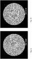
- the Figures 3a to 3 i each show Ronchigrams, which are bright field images of round bundles of rays that are used for imaging, for example the rays of a scanning electron microscope that would scan the object.
- a central area can be seen which, due to the very high magnification (image with an almost punctiform focused probe), has no structures. This means that the focus of this central aperture area is almost ideal.
- This area is surrounded by essentially hexagonal structures.
- the outer aperture areas are namely imaged in 3 or 6-fold tails of the focused probe, so that larger areas of the object (assumed to be amorphous) are hit, i.e. the magnification decreases, whereby structures become visible.
- Figure 3a a Ronchigram of the corrector according to Müller et al. (2006 - see above). It is a two-hexapole corrector without optimization. The flawless aperture of the beam is 50 mrad.
- Figure 3b shows a Ronchigram of the same corrector in an optimized state, with the error-free aperture of the beam having 68 mrad.
- EP 3c shows a Ronchigram of the EP 2 325 862 A1 or.
- EP 2 325 863 B1 (each from S. Henstra - see above) known two-hexapole corrector with double normal excitation of the hexapoles and the additional multipole with the reference number 126.
- the error-free aperture of the beam is 45 mrad.
- 3d shows a Ronchigram of this corrector with optimization of the phase shift, whereby an error-free aperture of 64 mrad is achieved.
- Figure 3e shows the Henstra corrector acc. 3c and 3d with the additional twelve-pole with the reference numeral 128. Due to the rim error (G 7 ) introduced by the twelve-pole, the error-free aperture is only 44 mrad.
- the Figures 3f and 3g show the above delta corrector with and without compensation, achieving error-free apertures of 50 mrad and 70 mrad.
Description
Die Erfindung betrifft einen teilchenoptischen Korrektor zum Korrigieren der Öffnungsfehler eines Elektronenmikroskops unter Vermeidung des dreizähligen axialen Astigmatismus, des axialen Dreilappfehlers vierter Ordnung und des sechszähligen axialen Astigmatismus, wobei der Korrektor ein zentrales Multipolelement der Länge L zur Erzeugung eines Hexapolfeldes in der Symmetrieebene des Korrektors sowie zwei äußere identische Multipolelemente der Länge L' zur Erzeugung gleich starker Hexapolfelder und zwei Rundlinsendupletts mit Rundlinsen aufweist, wobei die zur Symmetrieebene näheren Rundlinsen zur Symmetrieebene im Abstand der Brennweiten der Rundlinsen angeordnet sind, und die zur Symmetrieebene weiter entfernten Rundlinsen von letzteren einen Abstand aufweisen, der ihren Brennweiten zuzüglich der Brennweiten der Rundlinsen, die näher zur Symmetrieebene liegen, entspricht.The invention relates to a particle-optical corrector for correcting the spherical aberration of an electron microscope while avoiding the three-fold axial astigmatism, the fourth-order axial three-lobe error and the six-fold axial astigmatism, the corrector having a central multipole element of length L for generating a hexapole field in the plane of symmetry of the corrector and two outer identical multipole elements of length L ' for generating equally strong hexapole fields and two round lens doublets with round lenses, the round lenses closer to the plane of symmetry being arranged at a distance of the focal lengths of the round lenses from the plane of symmetry, and the round lenses further away from the plane of symmetry being at a distance from the latter corresponds to their focal lengths plus the focal lengths of the circular lenses that are closer to the plane of symmetry.
Elektronenoptische Abbildungssysteme werden sowohl zur Vergrößerung, wie im Fall der Elektronenmikroskopie, als auch zur Verkleinerung in der Elektronenprojektionslithographie eingesetzt. Der Vorteil gegenüber lichtoptischen Abbildungssystemen ist ihr wesentlich höheres Auflösungsvermögen, das sich aus der wesentlich geringeren Wellenlänge der abbildenden optischen Strahlung ergibt. Gegenüber Licht erbringen elektronenoptische Abbildungssysteme in Abhängigkeit von der Beschleunigungsspannung eine Verbesserung der Auflösung um einen Faktor von ca. 104, so daß Abbildungen bis in den Atombereich möglich sind.Electron-optical imaging systems are used both for enlargement, as in the case of electron microscopy, and for reduction in electron projection lithography. The advantage over light-optical imaging systems is their significantly higher resolution, which results from the significantly lower wavelength of the imaging optical radiation. Compared to light, electron-optical imaging systems improve the resolution by a factor of about 10 4 depending on the acceleration voltage, so that images down to the atomic range are possible.
Die Führung von Elektronenstrahlen zum Zwecke der Abbildung erfolgt mit Hilfe elektrischer und/oder magnetischer Linsen. Derartige Linsensysteme sind in Abhängigkeit von ihrem Aufbau und ihrer Anordnung in höherem Maße als lichtoptische Systeme mit unterschiedlichen Bildfehlern behaftet.Electron beams are guided for the purpose of imaging with the aid of electric and/or magnetic lenses. Depending on their structure and their arrangement, such lens systems are afflicted with different image errors to a greater extent than light-optical systems.
Der Zweck teilchenoptischer Korrektoren besteht darin, Öffnungs- und gegebenenfalls Farbfehler der optischen Bauteile des Mikroskops zu kompensieren. Durch die Kompensation mittels solcher Korrektoren werden aber auch Fehler vom Korrektor selbst verursacht.The purpose of particle-optical correctors is to compensate for aperture errors and, if applicable, chromatic errors in the optical components of the microscope. through the Compensation by means of such correctors, however, errors are also caused by the corrector itself.
Bei diesen Fehlern handelt es sich zum einen um parasitäre Fehler, resultierend aus Material- und Dimensionierungsfehlern sowie Justierfehlern. Zum anderen gibt es intrinsische residuale Fehler, diese sind physikalisch bedingt, das heißt, sie würden auch bei einer bautechnisch fehlerlosen Teilchenoptik auftreten. Letztere müssen in Kauf genommen werden, um den primären Zweck der Korrektur der abbildenden Linsen erreichen zu können. Für die mit Hilfe der Korrektur beste erreichbare optische Qualität der Abbildung ist es notwendig, diese residualen Fehler zu minimieren oder besser weitgehend zu vermeiden.On the one hand, these errors are parasitic errors resulting from material and dimensioning errors as well as adjustment errors. On the other hand, there are intrinsic residual errors, which are physically caused, which means that they would also occur in particle optics that were structurally flawless. The latter must be accepted in order to be able to achieve the primary purpose of correcting the imaging lenses. For the best optical quality of the image that can be achieved with the help of the correction, it is necessary to minimize these residual errors or, better still, to largely avoid them.
Unter den Fehlern gibt es chromatische und geometrische Fehler. Die geometrischen Fehler werden nach Bildfehlerfiguren eingeteilt, welche in verschiedenen Ordnungen auftreten, dabei ist eine Klassifizierung nach der Seidel-Ordnung üblich. Eine Aufstellung solcher Fehler findet sich in
Die Grundlage für die Funktion aller Korrektoren in der Teilchenoptik bildet die Erkenntnis von O. Scherzer (
Die Fehlerkorrektur läuft darauf hinaus, daß der Korrektor Fehler erzeugt, die den Fehlern des optischen Systems entgegengesetzt sind und diese dadurch kompensieren. Allerdings ist es so, daß solche Korrektoren auch selbst wieder Fehler erzeugen, welche soweit wie möglich innerhalb des Korrektors ebenfalls kompensiert werden müssen.Correcting errors means that the corrector produces errors that oppose the errors of the optical system and thereby compensate for them. However, it is the case that such correctors also produce errors themselves, which must also be compensated for as far as possible within the corrector.
Die geometrischen Fehler deformieren die Wellenfronten des Lichts bzw. in der Teilchenoptik der Teilchenstrahlen in eine nicht sphärische Form, wobei der Korrektor diese Form in möglichst hohem Maß wieder herstellen muß oder derart deformieren muß, daß sie nach dem Auftreten nachfolgender Fehler wieder sphärisch wird. Bezüglich der Grundzüge dieser Korrektur der Wellenfronten wird auf Rolf Erni (a.a.O., Seiten 214 - 228, Kapitel "7.5 Wave Surface, Aberration Funktion and Image Aberrations") verwiesen.The geometric errors deform the wave fronts of the light or, in particle optics, the particle beams into a non-spherical shape, with the corrector having to restore this shape to the greatest possible extent or deform it in such a way that it becomes spherical again after the occurrence of subsequent errors. Regarding the basics of this Correction of the wave fronts is referred to Rolf Erni (ibid., pages 214 - 228, chapter "7.5 Wave Surface, Aberration Function and Image Aberrations").
Das Ganze dient dazu, hochaufgelöste Bilder dünner Schichten innerhalb einer Probe zu erzielen - letztlich eine optimale Einstellung des Mikroskops. Dies wird um so mehr erreicht, je höher die Ordnung der Fehler ist, bis zu der alle Fehlerordnungen kompensiert sind. Das Problem dabei ist jedoch, daß in der Praxis - im Gegensatz zur Theorie, die sich berechnen läßt -jede weitere Fehlerkorrektur wieder Rückwirkungen auf bereits kompensierte Fehler hat, die dann wieder auftauchen und erneut kompensiert werden müssen. Dadurch muß man sich einer optimalen Fehlerkorrektur in einer iterativen Systematik annähern. In der Praxis ist es somit nicht möglich, alle Fehler bis zu einer bestimmten Ordnung restlos zu beseitigen, aber sie soweit zu vermindern, daß sie die gewünschte Bildqualität bezüglich Auflösung und Schärfe nicht mehr ergebnisrelevant beeinflussen. Das Ziel ist also theoretisch zwar absolut, in der Praxis geht es jedoch um die Verfügbarkeit der Bildqualität für den jeweiligen Einsatzzweck, dem ein Elektronenmikroskop dient. Wenn man also von der Beseitigung oder Korrektur eines Fehlers spricht, so ist das in diesem Sinne gemeint.The whole purpose is to achieve high-resolution images of thin layers within a sample - ultimately an optimal setting of the microscope. This is all the more achieved the higher the order of the errors is, up to which all error orders are compensated. However, the problem here is that in practice - in contrast to theory, which can be calculated - each additional error correction has repercussions on errors that have already been compensated, which then reappear and have to be compensated again. As a result, an optimal error correction must be approached in an iterative system. In practice, it is therefore not possible to completely eliminate all errors up to a certain level, but to reduce them to such an extent that they no longer affect the desired image quality in terms of resolution and sharpness in a way that is relevant to the result. So while the goal is theoretically absolute, in practice it is about the availability of image quality for the particular application that an electron microscope is used for. So when one speaks of the elimination or correction of an error, it is meant in this sense.
Bekannt sind Öffnungsfehlerkorrektoren, die residuale axiale Fehler bis zur fünften Ordnung vermeiden. Wenn aber bei diesen Korrektoren die Fehler bis zur fünften Ordnung korrigiert sind, wird ein Dreilappfehler sechster Ordnung derart dominant, daß dieser in nicht akzeptabler Weise die Bildqualität stört, wenn man die Objektivapertur weiter öffnet. Bei den bekannten Korrektoren handelt es sich um solche mit zwei oder drei Hexapolen mit zwischengeordneten Rundlinsendupletts.Spherical aberration correctors are known which avoid residual axial errors up to the fifth order. However, if these correctors are corrected up to the fifth order, a sixth-order three-lobe error becomes so dominant that it unacceptably disturbs the image quality when the objective aperture is opened further. The known correctors are those with two or three hexapoles with interposed circular lens doublets.
Bei den Korrektoren mit zwei Hexapolen handelt es sich um den Korrektor
In der
Mit der Frage, ob sich mit diesen Korrektoren mit zwei oder drei Hexapolen der Dreilappfehler sechster Ordnung beseitigen läßt, setzt sich die Abhandlung von
In der
Der Deltakorrektor (siehe oben) ist ein Korrektor der eingangs genannten Art, mit dem sich der Öffnungsfehler (Cs) unter Vermeidung des axialen Astigmatismus (A2), des axialen Dreilappfehlers vierter Ordnung (D4) und des sechszähligen axialen Astigmatismus (A5) korrigieren läßt, jedoch nicht der Dreilappfehler sechster Ordnung (D6). Dies wurde von Morishita et. al. (siehe oben) sowohl rechnerisch als auch experimentell untersucht und das Ergebnis auf Seite 162 (links oben) zusammengefaßt (a.a.O.).The delta corrector (see above) is a corrector of the type mentioned above, with which the spherical aberration (C s ) is corrected while avoiding the axial astigmatism (A 2 ), the fourth-order axial three-lobe aberration (D 4 ) and the six-fold axial astigmatism (A 5 ) can be corrected, but not the sixth-order three-lobe error (D 6 ). This was reported by Morishita et. al. (see above) both computationally and experimentally and the result is summarized on page 162 (top left) (ibid.).
Der Erfindung liegt daher die Aufgabe zugrunde, einen Öffnungsfehlerkorrektor verfügbar zu machen, der alle unrunden axialen Fehler bis zur fünften Ordnung und den Dreilappfehler sechster Ordnung vermeidet, ohne Fehler einzuführen, welche die dadurch erzielte Verbesserung wieder zunichte machen.The invention is therefore based on the object of making a spherical aberration corrector available which avoids all out-of-round axial errors up to the fifth order and the sixth-order three-lobe error without introducing errors which again nullify the improvement achieved thereby.
Die Aufgabe wird bei einem teilchenoptischen Korrektor der eingangs genannten Art dadurch gelöst, daß die Stärke des zentralen Hexapolfeldes zu den Stärken der beiden gleich starken äußeren Hexapolfelder derart gewählt ist, daß der dreizählige axiale Astigmatismus verschwindet und die Stärken letzterer so gewählt sind, daß der Korrektor insgesamt keinen sechszähligen axialen Astigmatismus hat, daß der Abstand der Multipolelemente von den der Symmetrieebene weiter entfernten Rundlinsen, deren Brennweite zuzüglich eines weiteren Abstandes entspricht, wobei letzterer so gewählt ist, daß für die gegebenen Längen des zentralen Multipolelements und der gegebenen Längen der identischen Multipolelemente der axiale Dreilappfehler vierter Ordnung verschwindet, und daß die Länge des zentralen Multipolelements im Verhältnis zu den Längen der zwei äußeren identischen Multipolelemente derart gewählt ist, daß der axiale Dreilappfehler sechster Ordnung - für das vorgegebene Verhältnis der Brennweite der zur Symmetrieebene näheren Rundlinsen zu der Brennweite der zur Symmetrieebene weiter entfernten Rundlinsen - verschwindet.The object is achieved with a particle-optical corrector of the type mentioned at the outset in that the strength of the central hexapole field is selected in relation to the strengths of the two equally strong outer hexapole fields in such a way that the three-fold axial astigmatism disappears and the strengths of the latter are selected in such a way that the corrector overall has no six-fold axial astigmatism, that the distance between the multipole elements and the circular lenses further away from the plane of symmetry corresponds to their focal length plus a further distance, the latter being selected in such a way that for the given lengths of the central multipole element and the given lengths of the identical multipole elements fourth-order axial trilobe error disappears, and that the length of the central multipole element in relation to the lengths of the two outer identical multipole elements is chosen such that the sixth-order axial trilobe error - for the given focal length ratio d he circular lenses that are closer to the plane of symmetry to the focal length of the circular lenses that are further away from the plane of symmetry - disappears.
Der Ausgangspunkt der Erfindung besteht darin, daß sich die internen Kombinationsfehler des dreizähligen axialen Astigmatismus (A2) und des axialen Dreilappfehlers vierter Ordnung (D4) mit dem Hexapolfeld einerseits und des sechszähligen axialen Astigmatismus (A5) mit dem Hexapolfeld andererseits gegenseitig eliminieren müssen. Dies ist so zu verstehen, daß der Strahl durch ein Hexapolfeld zuerst deformiert wird und dann durch ein nachfolgendes Hexapolfeld wieder rund gemacht wird. Im unrunden Strahlbereich werden einerseits unerwünschte schon vorhandene Fehler beseitigt, andererseits für eine Kompensation nachfolgender Fehler dieselben Fehler mit umgekehrtem Vorzeichen für die nachfolgende Kompensation erzeugt. Bei den Multipolelementen der Erfindung findet diese Deformierung und das Wieder-rund-machen folgendermaßen statt: Der Strahl tritt in das erste Multipolelement ein, wird dort deformiert und in der ersten Hälfte (vor der Symmetrieebene) des zentralen Multipolelements nach einer Fehlerkompensation der vorgenannten Art wieder rund gemacht. In der zweiten Hälfte des zentralen Multipolelements (nach der Symmetrieebene) wird der Strahl nochmals deformiert, um dann im zweiten Multipolelement, das mit dem ersten identisch ist, wieder rund gemacht zu werden. Auch dort werden im unrunden Strahlenbereich Fehler kompensiert.The starting point of the invention is that the internal combination errors of the three-fold axial astigmatism (A 2 ) and the fourth-order axial three-lobe error (D 4 ) with the hexapole field on the one hand and the six-fold axial astigmatism (A 5 ) with the hexapole field on the other hand must eliminate each other . This is to be understood as meaning that the beam is first deformed by a hexapole field and then made round again by a subsequent hexapole field. In the non-round beam area, on the one hand, undesired errors that are already present are eliminated, and on the other hand, the same errors are generated with the opposite sign for the subsequent compensation to compensate for subsequent errors. In the multipole elements of the invention, this deformation and re-rounding takes place as follows: the beam enters the first multipole element, is deformed there and in the first half (before the plane of symmetry) of the central multipole element after an error compensation of the type mentioned above again rounded. In the second half of the central multipole element (after the plane of symmetry) the beam is deformed again in order to be made round again in the second multipole element, which is identical to the first one. There, too, errors are compensated for in the non-round beam area.
Die oben genannten Kombinationsfehler ergeben im Hexapolfeld durch Vektoren in einer zweidimensionalen Ebene darstellbare Fehlerbeiträge, nämlich a =̂ D4 + A2 mit Hexapolfeld und b =̂ A5 mit Hexapolfeld. Ohne die Erfindung bilden diese Vektoren a und b ein Dreieck, wobei die dritte Seite c des Dreiecks der Vektor des resultierenden axialen Dreilappfehlers sechster Ordnung (D6) ist. In der bekannten Literatur (z. B. Morishita et. al. - siehe oben) wirken diese teilweise in die gleiche Richtung, so daß die Resultante c betragsgemäß größer als a und b alleine ist. Ziel der Erfindung ist es, daß die beiden Vektoren a und b parallel gegeneinander gerichtet sind und damit der axiale Dreilappfehler sechster Ordnung (D6) zu Null gebracht wird.The combination errors mentioned above result in error contributions in the hexapole field that can be represented by vectors in a two-dimensional plane, namely a = ̂ D 4 + A 2 with hexapole field and b = ̂ A 5 with hexapole field. Without the invention, these vectors a and b form a triangle, with the third side c of the triangle being the vector of the resulting sixth-order axial trilobal error (D 6 ). In the known literature (e.g. Morishita et. al. - see above), these partly work in the same direction, so that the resultant c is larger than a and b alone in terms of absolute value. The aim of the invention is that the two vectors a and b are directed parallel to one another and thus the axial three-lobe error of the sixth order (D 6 ) is reduced to zero.
Dabei ist es das weitere Ziel, den Strahl mit dieser Fehlerfreiheit mit möglichst großem Aperturwinkel (α) in die Probe zu fokussieren, um die Beugungsbegrenzung gering zu halten. Maß für die Beugungsbegrenzung ist λ / α . Bei der Lichtoptik ist der Winkel α viel größer als bei der Elektronenmikroskopie. Daß aber letztere eine viel geringere Beugungsbegrenzung hat, liegt daran, daß die Wellenlänge λ bei Elektronenstrahlen viel geringer ist als bei Lichtwellen.The further goal is to focus the beam into the sample with this freedom from errors with the largest possible aperture angle (α) in order to keep the diffraction limitation low. The measure of the diffraction limitation is λ/ α . In light optics, the angle α is much larger than in electron microscopy. However, the fact that the latter has a much lower diffraction limitation is due to the fact that the wavelength λ is much smaller for electron beams than for light waves.
Bei der Erfindung sind vier Verhältnisse ausschlaggebend:
Zum einen das Verhältnis der Hexapolstärken, also der Stärke des zentralen Multipols (ΨHP2 ) zu den Stärken (ΨHP1,3 ) der beiden anderen äußeren identischen Multipolelemente. (Zur Erzeugung der Hexapolfelder können Hexapolelemente oder Multipolelemente mit mehr Polen eingesetzt werden.)In the invention, four ratios are decisive:
On the one hand, the ratio of the hexapole strengths, i.e. the strength of the central multipole ( Ψ HP2 ) to the strengths ( Ψ HP1,3 ) of the other two outer identical multipole elements. (Hexapole elements or multipole elements with more poles can be used to generate the hexapole fields.)
Zum anderen müssen die Stärken der äußeren Hexapolfelder so gewählt sein, daß der Korrektor insgesamt keinen sechszähligen axialen Astigmatismus hat.On the other hand, the strengths of the outer hexapole fields must be selected in such a way that the corrector as a whole does not have a six-fold axial astigmatism.
Weiterhin ist das Verhältnis d des Maßes des weiteren Abstands der Mittelebenen der äußeren identischen Hexapole zu den Brennebenen der äußeren Transferlinsen (7", 8") Δz zur Länge L'der äußeren identischen Multipolelemente (1, 3) relevant.Furthermore, the ratio d of the extent of the further distance of the center planes of the outer identical hexapoles to the focal planes of the outer transfer lenses (7", 8") Δz to the length L ' of the outer identical multipole elements (1, 3) is relevant.
Außerdem das Verhältnis der Länge L des zentralen Multipolelements 2 zur Länge L'der zwei äußeren identischen Multipolelemente 1 und 3.Also the ratio of the length L of the
Zum Verhältnis der Hexapolstärken ΨHP2 zu ΨHP1,3:
Die Stärke der Hexapolfelder Ψ ergibt sich aus der Windungszahl N multipliziert mit der Stromstärke I, außerdem ist noch der Radius R der Bohrung nach folgender Formel relevant: Stärke des Hexapols: ![]()
The strength of the hexapole fields Ψ results from the number of turns N multiplied by the current intensity I. The radius R of the bore is also relevant according to the following formula: Strength of the hexapole:![]()
Permeabilität des Vakuums: ![]()
![]()
Das erforderliche Stärkeverhältnis des zentralen Hexapolfeldes ΨHP1 zu der Stärke der beiden anderen identischen Hexapolfelder ΨHP2,3 wird durch folgende Formel wiedergegeben, welche zur Freiheit vom dreizähligen axialen Astigmatismus (A2) führt: ![]()
![]()
Dabei ist k das Verhältnis der Länge L des zentralen Multipolelements (2) zu den Längen L' der beiden anderen identischen Multipolelemente (1, 3), also ![]()
![]()
M ist das Verhältnis der Brennweiten f der näher zur Symmetrieebene liegenden Rundlinsen (7', 8') zu den Brennweiten f' der weiter weg liegenden (7", 8"), also ![]()
![]()
Zu den Stärken (ΨHP1,3 ) der äußern Hexapolfelder:
Diese müssen so gewählt sein, daß der Korrektor insgesamt keinen sechszähligen axialen Astigmatismus (A5) hat. Mit diesem Problem hat sich schon die oben genannte Veröffentlichung Müller et.al. (2006) beschäftigt, wobei es sich bei diesem Korrektor um einen Zweihexapolkorrektor handelte, bei dem die x-Komponente des A5-Fehlers (A5x) beseitigt wurde, jedoch noch eine geringe y-Komponente des Fehlers A5, also ein A5y übrigbleibt. Da es sich bei der Erfindung jedoch um einen Dreihexapolkorrektor handelt, verschwindet dieses A5y aus Symmetriegründen.On the strengths ( Ψ HP1,3 ) of the outer hexapole fields:
These must be selected in such a way that the corrector does not have a six-fold axial astigmatism (A 5 ). With this problem has been the above Publication Müller et al. (2006), where this corrector was a two-hexapole corrector in which the x-component of the A 5 error (A 5x ) was eliminated, but still a small y-component of the error A 5 , i.e. an A 5y remains. However, since the invention is a three-hexapole corrector, this A 5y disappears for reasons of symmetry.
Zum Maß des weiteren Abstandes Δz:
Dies ist die Verschiebung der Mittelebenen der beiden identischen äußeren Multipole zusätzlich zur Entfernung der Brennweite f' der äußeren Rundlinsen (7" und 8"), also von den Brennpunkten nach außen.Regarding the further distance Δz :
This is the shift of the center planes of the two identical outer multipoles in addition to the removal of the focal length f ' of the outer circular lenses (7" and 8"), i.e. outwards from the focal points.
Für das Verhältnis d des Maßes Δz zur Länge L' der beiden identischen Multipolelemente (1 und 2) gilt*: ![]()
![]()
Damit muß etwa gelten: ![]()
![]()
Damit verschwindet der Dreilappfehler vierter Ordnung (D4). k und M sind schon oben definiert. Bei dieser Formel* handelt es sich um eine Näherungsformel, da sie von der Annahme eines kastenförmigen Hexapolfeldes ausgeht (real quillt das Hexapolfeld etwas über die Länge L bzw. L'hinaus). The fourth-order three-lobe error (D 4 ) thus disappears. k and M are already defined above. This formula* is an approximate formula, as it assumes a box-shaped hexapole field (in reality, the hexapole field swells somewhat beyond the length L or L' ) .
Erfindungsgemäß muß auch dieses Merkmal der Freiheit vom Dreilappfehler vierter Ordnung (D4) erfüllt sein. Beim Deltakorrektor ist dieses Verhältnis anders, dort ist d = 0 und somit Δz = 0. Die beiden äußeren Hexapolfelder liegen beim Deltakorrektor in den Brennweiten der - im Vergleich zur Symmetrieebene - äußeren Rundlinsen, dafür sind die äußeren Hexapolelemente zur Erfüllung der Freiheit vom axialen Dreilappfehler vierter Ordnung (D4) gegeneinander verdreht (siehe die oben genannte Abhandlung von Morishita et. al., dort S. 158, Fig. 1b).According to the invention, this feature of freedom from fourth-order three-lobe errors (D 4 ) must also be fulfilled. With the delta corrector, this ratio is different, where d = 0 and thus Δz = 0. With the delta corrector, the two outer hexapole fields are in the focal lengths of the outer round lenses - compared to the plane of symmetry - but the outer hexapole elements are there to ensure freedom from the axial three-lobe error fourth order (D 4 ) rotated against each other (see the above-mentioned paper by Morishita et. al., there p. 158, Fig. 1b).
Zum Verhältnis der Länge L des zentralen Multipolelements 2 zu den Längen L' der äußeren identischen Multipolelemente 1 und 3:
Hier geht es um die Bedingung dafür, daß sich die beiden Vektoren a und b gegenseitig aufheben, also die in allen Hexapolfeldern entstehenden Fehler A2 und D4 nachfolgend in diesen Hexapolfeldern einen Kombinationsfehler D6 erzeugen, der durch den entgegengerichteten Kombinationsfehler D6 im zentralen Hexapolfeld, verursacht durch den Fehler A5, aufgehoben wird. Erreicht wird diese Aufhebung durch die Wahl der Länge L des zentralen Multipolelements 2 zu den Längen L'der identischen Multipolelementen 1 und 3.Regarding the ratio of the length L of the
This is about the condition that the two vectors a and b cancel each other out, i.e. the errors A 2 and D 4 occurring in all hexapole fields subsequently produce a combination error D 6 in these hexapole fields, which is caused by the opposing combination error D 6 in the central Hexapole field caused by the error A 5 is canceled. This cancellation is achieved by choosing the length L of the
Für den (im Falle der Erfindung näherungsweise reellen) Vektor a läßt sich dies mit folgender Formel beschreiben: ![]()
![]()
Und für den Vektor b: ![]()
![]()
Dabei sind X 〈A2 〉, X 〈D4〉 und X 〈A5〉 die Fehlerbahnen der Fehler A2, D4 und A5 und uα ist die axiale Fundamentalbahn, die von der Strahlenquelle kommt und durch die Objektivlinse in die Objektebene fokussiert wird. Die y-Komponenten der Vektoren sind aufgrund der identischen Orientierung der Hexapole (im Gegensatz zum Deltakorrektor) vernachlässigbar.Here X 〈 A 2 〉 , X 〈 D4 〉 and X 〈A5〉 are the error trajectories of errors A 2 , D 4 and A 5 and u α is the axial fundamental trajectory coming from the radiation source and focused into the object plane by the objective lens becomes. The y-components of the vectors are negligible due to the identical orientation of the hexapoles (in contrast to the delta corrector).
Letztlich sind die vorgenannten drei Verhältnisse - wie schon aus den Formeln ersichtlich - miteinander verknüpft, wobei es darauf ankommt, jeweils Werte zu finden, welche die drei genannten Bedingungen erfüllen. Die theoretische Bedingungserfüllung muß dann natürlich noch den konkreten Verhältnissen für konkrete Elektronenmikroskope angepaßt werden, die ja je nach Anforderungen und Einsatzzweck unterschiedlich sind und baufehlerbedingte Abweichungen von der theoretischen Berechnung aufweisen.Ultimately, as can be seen from the formulas, the three ratios mentioned above are linked to one another, and it is important to find values that fulfill the three conditions mentioned. The fulfillment of the theoretical conditions must of course still be adapted to the specific conditions for specific electron microscopes, which are different depending on the requirements and application and show deviations from the theoretical calculation due to construction errors.
Ein Strahlengang, wie beansprucht und mittels eines Ausführungsbeispiels in
Es besteht aber die Möglichkeit, solchen Fehlern entgegenzusteuern, indem man bestimmte Parameter geringfügig verändert, wie zum Beispiel eine Veränderung der Erregung einer Linse mit der Folge einer geringen Veränderung des Strahlengangs, der dann aber durch eine veränderte Erregung einer anderen Linse wieder korrigiert wird, damit der erfindungsgemäße Fokus erhalten bleibt. Typischerweise reicht dazu eine Erregungsveränderung in einem Bereich bis zu 5% aus. Es wird also ein gewisser Justierfreiheitsgrad genutzt.However, there is the possibility of counteracting such errors by slightly changing certain parameters, such as changing the excitation of a lens with the result of a slight change in the beam path, which is then corrected again by changing the excitation of another lens the focus of the invention is retained. Typically, a change in excitation in a range of up to 5% is sufficient. A certain degree of adjustment freedom is therefore used.
Beispiele für solche korrigierenden Veränderungen sind Veränderungen der Erregung einer oder beider äußeren Rundlinsen (im gezeichneten Ausführungsbeispiel sind dies 7" und 8") mit einer Fokuskorrektur durch eine Erregungsveränderung der an den jeweiligen äußeren Hexapol angrenzenden Linse, nämlich der Kondensorlinse (16) oder der ersten Transferlinse (11'). Auch andere derartige Möglichkeiten sind denkbar.Examples of such corrective changes are changes in the excitation of one or both outer round lenses (in the illustrated embodiment these are 7" and 8") with a focus correction by changing the excitation of the lens adjacent to the respective outer hexapole, namely the condenser lens (16) or the first transfer lens (11'). Other such possibilities are also conceivable.
Bei der Vornahme einer solchen Korrektur geben die unerwünschten parasitären Fehler an, in welche Richtung die Korrektur vorzunehmen ist. Das Ausmaß der Korrektur erfolgt dann ergebnisorientiert.When making such a correction, the unwanted parasitic errors indicate in which direction the correction should be made. The extent of the correction is then result-oriented.
Solche sehr begrenzte Abweichungen lösten entsprechend begrenzte Abweichungen anderer Parameter aus. Wie dies im Grunde genommen bei jeder, durch mechanische oder elektrische Parameter definierten Erfindung der Fall ist, müssen somit auch hier innerhalb der funktionalen Ergebniserzielung Toleranzbereiche in den Schutzbereich einbezogen werden. Die Einbeziehung von Grenzbereichen in den Schutzbereich ergibt sich ohnehin schon daraus, daß Strahlenbegrenzungen in einem realen Strahlengang immer Bereiche und keine exakten Linien darstellen.Such very limited deviations triggered correspondingly limited deviations in other parameters. As is basically the case with every invention defined by mechanical or electrical parameters, tolerance ranges must also be included in the scope of protection within the functional achievement of results. In any case, the inclusion of border areas in the protection area results from the fact that beam limitations in a real beam path always represent areas and not exact lines.
Dies ist keine Abweichung vom erfindungsgemäßen Prinzip, sondern eine Korrektur in der realen Ausführung, um der Erzielung des erfindungsgemäßen Prinzips zu dienen.This is not a deviation from the principle according to the invention, but a correction in the real embodiment in order to serve to achieve the principle according to the invention.
Die Unteransprüche 2 bis 7 geben zweckmäßige Bereiche und konkrete optimale Verhältnisse an:
Das Verhältnis d = Δz / L', also des weiteren Abstandes Δz zu den Längen L' der äußeren identischen Multipolelemente 1 und 3, liegt zweckmäßigerweise in einem Bereich von 0,5 bis 0,95.
The ratio d= Δz / L′, ie the further distance Δz to the lengths L ′ of the outer identical multipole elements 1 and 3, is expediently in a range from 0.5 to 0.95.
Das Verhältnis der Stärke des Hexapolfeldes Ψ HP2 des zentralen Multipolelements 2 zur Stärke Ψ HP1,3, also, ![]()
![]()
Das Verhältnis M der Brennweiten f' der näher an der Symmetrieebene 6 liegenden Rundlinsen 7' und 8' zu den Brennweiten f' der weiter entfernt liegenden Rundlinsen 7" und 8", also M = f / f', liegt zweckmäßigerweise in einem Bereich von 0,8 bis 1,2, vorzugsweise jedoch bei M= 1,15 mit einer Toleranz von ± 0,01.The ratio M of the focal lengths f ' of the round lenses 7' and 8' closer to the plane of
Das Verhältnis k der Länge L des zentralen Multipolelements 2 zu der Länge L' der äußeren Multipole 1 und 3, also k = L / L' in einem Bereich von 2,0 bis 3,5, vorzugsweise ist k=3,05(±0,05).The ratio k of the length L of the
Eine Weiterbildung des erfindungsgemäßen Korrektors dient der Kompensation von Baufehlern, wobei Fehler erzeugt werden, die die Fehler, welche durch Baufehler verursacht werden, kompensieren. Dazu ist vorgesehen, daß die Symmetrieebenen von zusätzlich zwischen den Rundlinsen der Rundlinsendupletts angeordneten Hexapoldupletts von den näher an der Symmetrieebene liegenden Rundlinsen in der Entfernung derer Brennweiten und von den zur Symmetrieebene weiter weg liegenden Rundlinsen in der Entfernung derer Brennweiten angeordnet sind, wobei die Hexapoldupletts derart aufgebaut und erregt sind, daß innerhalb des Korrektors kleine Variationen des Dreilappfehlers vierter Ordnung zur Kompensation von durch Baufehler verursachten Fehlern mit umgekehrten Vorzeichen erzeugt werden können.A further development of the corrector according to the invention serves to compensate for construction errors, with errors being generated which compensate for the errors caused by construction errors. For this purpose, it is provided that the planes of symmetry of hexapole doublets additionally arranged between the round lenses of the round lens doublets are arranged at the distance of their focal lengths from the round lenses lying closer to the plane of symmetry and at the distance of their focal lengths from the round lenses lying further away from the plane of symmetry, with the hexapole doublets being arranged in such a are constructed and excited so that small variations of the fourth order three-lobe error can be generated within the corrector to compensate for errors of reversed sign caused by construction errors.
Weitere Baufehler können dadurch kompensiert werden, daß die Symmetrieebenen von zusätzlich zwischen den Rundlinsen der Rundlinsendupletts angeordneten Hexapoldupletts von den näher an der Symmetrieebene liegenden Rundlinsen in der Entfernung derer Brennweiten und von den zur Symmetrieebene weiter weg liegenden Rundlinsen in der Entfernung derer Brennweiten angeordnet sind, wobei die Hexapoldupletts derart aufgebaut und erregt sind, daß kleine Variationen der residualen Fehler, insbesondere D6, A5, möglich werden, die wiederum die Kompensation von parasitären Fehlern ermöglichen oder die Minimierung des Einflusses von Fehlern höherer Ordnung der gleichen Zähligkeit, insbesondere D8 und G7, ermöglichen.Further structural errors can be compensated for by the fact that the planes of symmetry of hexapole doublets additionally arranged between the round lenses of the round lens doublets are arranged at the distance of their focal lengths from the round lenses lying closer to the plane of symmetry and at the distance of their focal lengths from the round lenses lying further away from the plane of symmetry, with the hexapole doublets are constructed and excited in such a way that small variations in the residual errors, in particular D 6 , A 5 , become possible, which in turn allow the compensation of parasitic errors or the minimization of the influence of higher-order errors of the same order, in particular D 8 and G 7 , enable.
Bei dieser Kompensation handelt es sich nicht um eine Korrektur, sondern um eine die erfindungsgemäße Korrektur ergänzende Optimierung, ähnlich wie eingangs zur
Die Erfindung betrifft weiterhin ein Elektronenmikroskop, das mit dem oben beschriebenen Korrektor ausgestattet ist. Dabei handelt es sich vorzugsweise um ein Rasterelektronenmikroskop (REM) oder ein Raster-Transmissionselektronenmikroskop (STEM).The invention further relates to an electron microscope equipped with the corrector described above. This is preferably a scanning electron microscope (SEM) or a scanning transmission electron microscope (STEM).
Es kann sich auch um ein Transmissionselektronenmikroskop (TEM) handeln, bei dem der Korrektor bezüglich des Strahlengangs der Objektivlinse nachgeschaltet ist.It can also be a transmission electron microscope (TEM), in which the corrector with regard to the beam path is connected downstream of the objective lens.
Bei derartigen Transmissionselektronenmikroskopen ist der Strahlengang im Vergleich zu den vorgenannten Elektronenmikroskopen und dem beispielhaft in
Bei einem der vorgenannten Mikroskope ist zweckmäßigerweise zwischen dem Korrektor und der Objektivlinse ein Transferlinsensystem eingefügt, mit dem Öffnungsfehler korrigierbar sind. Ein solches Transferlinsensystem kann sowohl aus einer, als auch aus zwei Transferlinsen bestehen.In one of the aforementioned microscopes, a transfer lens system is expediently inserted between the corrector and the objective lens, with which spherical aberrations can be corrected. Such a transfer lens system can consist of either one or two transfer lenses.
Das Transferlinsensystem mit zwei Transferlinsen ist zweckmäßigerweise derart ausgebildet, daß die Transferlinsen derart verschiedene Brennweiten aufweisen, daß sich damit die Objektivlinsenöffnungsfehler eliminieren lassen. Dabei kann vorgesehen sein, daß mittels der Erregung der Spulen der Transferlinsen die Brennweiten der Transferlinsen zur Eliminierung der konkreten Objektivlinsenöffnungsfehler einstellbar sind.The transfer lens system with two transfer lenses is expediently designed in such a way that the transfer lenses have such different focal lengths that the objective lens aperture errors can be eliminated. Provision can be made for the focal lengths of the transfer lenses to be adjustable by means of the excitation of the coils of the transfer lenses in order to eliminate the specific objective lens aperture errors.
Die Erfindung wird nachfolgend anhand der Zeichnung erläutert. Es zeigen
- Fig. 1
- Ein Ausführungsbeispiel eines erfindungsgemäßen Korrektors sowie ein Transferlinsensystem und
- Fig. 2a, 2b und 2c
- ein Vergleich der Fehlerkompensation des Standes der Technik und der Erfindung anhand von Vektoren.
- 1
- An embodiment of a corrector according to the invention and a transfer lens system and
- Figures 2a, 2b and 2c
- a comparison of the error compensation of the prior art and the invention using vectors.
Außerdem ist anhand eines Ronchigramms,
In
Der Korrektor 5 besteht aus drei Multipolelementen 1, 2 und 3, einem zentralen Multipolelement 2, das in der Symmetrieebene 6 des Korrektors 5 liegt, und aus zwei äußeren Multipolelementen 1 und 3, die identisch sind. Das zentrale Multipolelement 2 weist ein Hexapolfeld der Stärke Ψ HP2 und eine Länge L auf. Die zwei äußeren Multipolelemente 1 und 3 weisen Hexapolfelder der Stärke Ψ HP1,3 und eine Länge L' auf. Zwischen den Multipolelementen 1, 2 und 3 sind Rundlinsendupletts 7 und 8 mit den Rundlinsen 7', 7" und 8', 8" angeordnet. Die Rundlinsen 7' und 8' sind in der Entfernung ihrer Brennweiten f von der Symmetrieebene 6 angeordnet und die Rundlinsen 7" und 8" mit den Brennweiten f' haben von den Rundlinsen 7' und 8' die Entfernung beider Brennweiten f und f'. Die äußeren identischen Multipolelemente 1 und 3 sind von den Rundlinsen 7" und 8" jeweils deren Brennweite f' und zuzüglich eines Maßes Δz entfernt, wobei sich diese Entfernungen jeweils auf die Symmetrieebenen 1', 6 und 3' der Hexapolelemente 1, 2 und 3 beziehen, beziehungsweise auch bei den Rundlinsen auf deren Symmetrieebenen.The
Wie oben schon beschrieben ist das Verhältnis der Stärke des Hexapolfeldes Ψ HP2 des zentralen Multipolelements 2 zu den Stärken der Hexapolfelder Ψ HP1,3 der äußeren Multipolelemente 1, 3 derart bemessen, daß der dreizählige Astigmatismus A2 verschwunden ist.As already described above, the ratio of the strength of the hexapole field Ψ HP2 of the
Gemäß der obigen näheren Beschreibung ist das Maß Δz erfindungsgemäß derart gewählt, daß für vorgegebene Längen L und L'der Multipolelemente 1, 2, und 3 der axiale Dreilappfehler vierter Ordnung D4 verschwindet. Wobei die Länge des zentralen Multipols 2 ein solches Verhältnis k zu den Längen L' der äußeren Multipolelemente 2 und 3 hat, daß für ein vorgegebenes Verhältnis M = f / f' der Brennweiten f der Rundlinsen 7' und 8' zu den Brennweiten f' der Rundlinsen 7" und 8" der axiale Dreilappfehler D6 erfindungsgemäß verschwunden ist.According to the detailed description above, the dimension Δz is selected according to the invention in such a way that for predetermined lengths L and L ′ of the
In dem Korrektor 5 tritt ein von der Strahlenquelle kommender und durch Kondensorlinse(n) gebündelter Strahl rund ein, der durch den axialen Strahlengang uα und den außeraxialen Strahlengang uγ dargestellt ist. Der Strahl wird zunächst durch das erste äußere Multipolelement 1 deformiert und in der ersten Hälfte des zentralen Multipolelements 2 wieder rund gemacht, danach in der zweiten Hälfte des Multipolelements 2 erneut dreizählig deformiert und mit dem dritten äußeren Multipolelement 3 wieder rund gemacht. Die unrunden Strahlbereiche dienen nach der Grundlage von O. Scherzer (siehe oben) der beschriebenen Fehlerkorrektur. Dies ist die Grundlage des erfindungsgemäßen teilchenoptischen Korrektors 5.In the
Weiterhin dargestellt sind zusätzliche Hexapoldupletts 9, 9' und 10, 10', welche zwischen den Rundlinsen 7' und 7" sowie 8' und 8" der Rundlinsendupletts 7 und 8 angeordnet sind, wobei deren Symmetrieebenen 9", 10" von den Rundlinsen 7', 7", 8', 8" jeweils eine Entfernung aufweisen, die deren Brennweiten f, f' entspricht.Also shown are additional
Der Aufbau und die Erregung dieser Hexapoldupletts 9, 9' und 10, 10' ist derart gewählt, daß zur Kompensation von durch Baufehler des Elektronenmikroskops oder des Korrektors 5 verursachten parasitären Bildfehlern erzeugte kleine Variationen des Dreilappfehlers vierter Ordnung D4 mittels der erzeugten, diesen Fehlern entgegengerichteten Fehlern, ausgelöscht werden können.The structure and the excitation of these
Die Zeichnung zeigt auch ein Transferlinsensystem 11, das dem Korrektor nachgeschaltet ist und über zwei Transferlinsen 11' und 11" verfügt. Diese weisen derart verschiedene Brennweiten f" und f‴ auf, daß sich dadurch die Öffnungsfehler der Objektivlinse 13, eliminieren lassen. Für eine genaue Einstellung dieser Elimination können die Brennweiten f", f‴ durch die Erregung der Spulen der Transferlinsen 11' und 11" in einem gewissen Bereich variiert werden. Die Elimination von Öffnungsfehlern muß vor dem Auftreffen des Strahls auf die Probe 14 erfolgen.The drawing also shows a
In dem Transferlinsensystem 11 können für ein Rasterelektronenmikroskop Elektromagnete 12, 12' für die Ablenkung des Rasterstrahls angeordnet sein.
Die
Dabei entsteht der Vektor a durch die Fehler A2 und D4 im Hexapolfeld und der Vektor b durch den Fehler A5 im Hexapolfeld. Der Vektor c ist die Resultante der Vektoren a und b und gibt den Fehler D6 an. Es handelt sich dabei um zweidimensionale Vektoren in einer Ebene senkrecht zur Symmetrieachse.The vector a is created by the errors A 2 and D 4 in the hexapole field and the vector b by the error A 5 in the hexapole field. The vector c is the resultant of the vectors a and b and gives the error D 6 . These are two-dimensional vectors in a plane perpendicular to the axis of symmetry.
Die
Die
Schließlich zeigt die
Die
Es zeigenShow it
Die
Die
- 11
- erstes äußeres Multipolelementfirst outer multipole element
- 1'1'
- Symmetrieebene des ersten äußeren MultipolelementsSymmetry plane of the first outer multipole element
- 22
- zentrales Multipolelementcentral multipole element
- 33
- zweites äußeres Multipolelementsecond outer multipole element
- 3'3'
- Symmetrieebene des zweiten äußeren MultipolelementsSymmetry plane of the second outer multipole element
- ΨHP2ΨHP2
- Stärke des Hexapolfeldes des zentralen MultipolelementsStrength of the hexapole field of the central multipole element
- ΨHP1,3ΨHP1,3
- Stärken der äußeren identischen Multipolelemente 1 und 3Strengths of the outer identical multipole elements 1 and 3
- LL
- Länge des zentralen Multipolelements 1Length of the central multipole element 1
- L'L'
-
Längen der identischen Multipolelemente 2 und 3Lengths of the
identical multipole elements 2 and 3 - 44
- optische Achseoptical axis
- 55
- Korrektorproofreader
- 66
- Symmetrieebene des KorrektorsCorrector plane of symmetry
- 77
- Rundlinsenduplettround lens doublet
- 7'7'
- Rundlinse (zur Symmetrieebene näher)Round lens (closer to the plane of symmetry)
- 7"7"
- Rundlinse (zur Symmetrieebene weiter)Round lens (on to the plane of symmetry)
- 88th
- Rundlinsenduplettround lens doublet
- 8'8th'
- Rundlinse (zur Symmetrieebene näher)Round lens (closer to the plane of symmetry)
- 8"8th"
- Rundlinse (zur Symmetrieebene weiter)Round lens (on to the plane of symmetry)
- ff
- Brennweiten von 7' und 8'Focal lengths of 7' and 8'
- f'f'
- Brennweiten von 7" und 8"Focal lengths of 7" and 8"
- ΔzΔz
- weiterer Abstandfurther distance
- 9,9'9.9'
- Hexapoldupletthexapole doublet
- 10, 10'10, 10'
- Hexapoldupletthexapole doublet
- 9", 10"9", 10"
-
Symmetrieebenen der Hexapoldupletts 9, 9' und 10, 10'Symmetry planes of the
hexapole doublets 9, 9' and 10, 10' - 1111
- Transferlinsensystemtransfer lens system
- 11'11'
- erste Transferlinsefirst transfer lens
- 11"11"
- zweie Transferlinsetwo transfer lenses
- f", f‴f", f‴
-
verschiedene Brennweiten der Transferlinsen 11', 11"different focal lengths of the
transfer lenses 11', 11" - 12, 12'12, 12'
- Elektromagnete zur Ablenkung des RasterstrahlsElectromagnets for deflecting the scanning beam
- 1313
- Objektivlinseobjective lens
- 13', 13"13', 13"
- Objektivlinsenfelderobjective lens fields
- fʺʺfʺʺ
- Brennweite ObjektivlinsenFocal length objective lenses
- 1414
- Probesample
- 1515
- Detektordetector
- 1616
- Kondensorlinsecondenser lens
- uαetc
- axialer Strahlengangaxial beam path
- uγuγ
- außeraxialer Strahlengangoff-axis beam path
- αa
- Aperturwinkelaperture angle
- aa
- Vektor der Fehler A2 und D4 im HexapolfeldVector of errors A 2 and D 4 in the hexapole field
- bb
- Vektor des Fehlers A5 im HexapolfeldVector of the error A 5 in the hexapole field
- cc
- Vektor des Fehlers D6, der die Resultante von a und b ist.Vector of the error D 6 which is the resultant of a and b.
- Beugung: λ / α Diffraction: λ / α
- relative Verschiebung: d = Δz / L' relative displacement: d = Δz / L'
- Zwischenvergrößerung: M = f / f' Intermediate magnification: M = f / f'
- Längenverhältnis: k = L / L' Aspect ratio: k = L / L'
-
Verhältnis der Hexapolstärken:

- Permeabilität des Vakuums: µ 0 = 4π · 10-7 As/VmPermeability of vacuum: µ 0 = 4 π · 10 -7 As/Vm
- Stärke des Hexapols: Ψ = µ 0 · N · I · R -3 Strength of the hexapole: Ψ = µ 0 N I R -3
-
D4 Regel:

-
D6x Integrale:


Claims (18)
- Particle-optical corrector (5) for correcting the spherical aberrations (C3, C5) of an electron microscope, thereby preventing the threefold axial astigmatism (A2), the axial three-lobed aberration of fourth order (D4) and the sixfold axial astigmatism (A5), wherein the corrector (5) comprises a central multipole element (2) of length L for generating a hexapole field (ΨHP2 ) in the symmetry plane (6) of the corrector as well as two outer identical multipole elements (1, 3) of length L'for generating identically strong hexapole fields (ΨHP1, ΨHP3 ) and two round lens doublets (7 and 8) with round lenses (7', 7", 8', 8"), wherein the round lenses (7' and 8') which are closer to the symmetry plane (6) are arranged at a separation of the focal lengths (f) of the round lenses (7', 8') with respect to the symmetry plane (6), and the round lenses (7", 8") which are further away from the symmetry plane (6) are disposed at a separation from the round lenses (7', 8') which corresponds to their focal lengths (f') plus the focal lengths (f) of the round lenses (7', 8') which are disposed closer to the symmetry plane (6),
characterized in that the strength of the central hexapole field (ΨHP2 ) with respect to the strengths of the two identically strong outer hexapole fields (ΨHP1,3 ) is chosen such that the threefold axial astigmatism (A2) vanishes and the strengths (ΨHP1,3 ) of the latter are chosen such that the overall corrector (5) does not have a sixfold axial astigmatism (A5), that the separation between the multipole elements (1 and 3) and round lenses (7", 8") located further away from the symmetry plane (6), corresponds to the focal length (f') thereof plus an additional separation (Δz), wherein the latter is chosen such that for the stated lengths L and L', the axial three-lobed aberration of fourth order (D4) vanishes and that the length (L) of the central multipole element (2) is selected relative to the lengths (L') of the two outer identical multipole elements (1 and 3) in such a manner that the axial three-lobed aberration of sixth order (D6) vanishes for the stated ratio (M = f / f') between the focal length (f) of the round lenses (7', 8') that are closer to the symmetry plane (6) and the focal length (f') of the round lenses (7", 8") that are further away from the symmetry plane. - Corrector according to claim 1, characterized in that the ratio (d) between the additional separation (Δz) and the lengths (L') of the outer multipole element (1 and 3) is between 0.5 and 0.95 (

- Corrector according to claim 1 or 2, characterized in that the strength of the hexapole field (ΨHP2 ) of the central multipole element (2) with respect to the strength (ΨHP1,3 ) of the outer hexapole fields (1, 3) is between 0.33 and 1.7

- Corrector according to one of the claims 1 to 3, characterized in that the ratio (M) between the focal lengths (f) of the round lenses (7', 8') located closer to the symmetry plane (6) and the focal lengths (f') of the round lenses (7", 8") located further away, i.e. M = f / f', is in a range between 0.8 and 1.2.
- Corrector according to claim 4, characterized in that M = 1.15 (± 0.01).
- Corrector according to any one of the claims 1 to 5, characterized in that the ratio (k) between the length (L) of the central multipole element (2) and the length (L') of the outer multipoles (1 and 3), i.e. k = L / L', is within a range of between 2.0 and 3.5.
- Corrector according to claim 6, characterized in that k = 3.05 (± 0.05).
- Corrector according to any one of the claims 1 to 7, characterized in that the symmetry planes (9" and 10") of hexapole doublets (9, 9'; 10, 10') which are additionally arranged between the round lenses (7', 7"; 8', 8") of the round lens doublets (7, 8) are arranged at a separation from the round lenses (7', 8') equal to their focal lengths (f) and are arranged at a separation from the round lenses (7" and 8") equal to their focal lengths (f'), wherein the hexapole doublets (9, 9'; 10, 10') are structured and excited in such a manner that within the corrector (5) small variations of the three-lobed aberration of fourth order (D4) can be generated for compensating aberrations caused by construction errors.
- Corrector according to any one of the claims 1 to 8, characterized in that the symmetry planes (9" and 10") of hexapole doublets (9, 9'; 10, 10') additionally arranged between the round lenses (7', 7"; 8', 8") of the round lens doublets (7, 8) are arranged at a separation from the round lenses (7', 8') equal to their focal lengths (f) and are arranged at a separation from the round lenses (7" and 8") equal to their focal lengths (f'), wherein the hexapole doublets (9, 9'; 10, 10') are structured and excited in such a manner that small variations of the residual aberrations, in particular D6, A5, become possible, which permit the compensation of parasitic aberrations or the minimization of the influence of higher order aberrations of the same multiplicity, in particular D8 and G7.
- Electron microscope, characterized in that it is provided with a corrector (5) according to one of the claims 1 to 9.
- Electron microscope according to claim 10, characterized in that it is a scanning electron microscope (REM).
- Electron microscope according to claim 10 and 11, characterized in that it is a scanning transmission electron microscope (STEM).
- Electron microscope according to claim 10, characterized in that it is a transmission electron microscope (TEM), in which the corrector (5) is arranged downstream of the objective lens (13) with respect to the beam path.
- Electron microscope according to any one of the claims 10 to 13, characterized in that a transfer lens system (11) is inserted between the corrector (5) and the objective lens (13), by means of which spherical aberrations can be corrected.
- Electron microscope according to claim 14, characterized in that the transfer lens system (11) consists of a single transfer lens.
- Electron microscope according to claim 14, characterized in that the transfer lens system (11) consists of two transfer lenses (11', 11").
- Electron microscope according to claim 16, characterized in that the transfer lenses (11', 11") have different focal lengths (f", f‴) such that objective lens spherical aberrations can be eliminated thereby.
- Electron microscope according to claim 17, characterized in that by means of excitation of the coils of the transfer lenses (11', 11"), the focal lengths (f",f‴) of the transfer lenses (11', 11") can be adjusted for eliminating the specific objective lens spherical aberrations.
Priority Applications (2)
| Application Number | Priority Date | Filing Date | Title |
|---|---|---|---|
| US16/932,711 US11081313B2 (en) | 2019-08-15 | 2020-07-18 | Particle-optical corrector which is free from axial aberrations of sixth order and electron microscope with corrector |
| JP2020136977A JP6991287B2 (en) | 2019-08-15 | 2020-08-14 | Electron microscope with 6th-order axial aberration-free particle optics corrector and corrector |
Applications Claiming Priority (1)
| Application Number | Priority Date | Filing Date | Title |
|---|---|---|---|
| DE102019122013.0A DE102019122013B3 (en) | 2019-08-15 | 2019-08-15 | Particle-optical corrector free of sixth-order axial errors and electron microscope with corrector |
Publications (2)
| Publication Number | Publication Date |
|---|---|
| EP3780064A1 EP3780064A1 (en) | 2021-02-17 |
| EP3780064B1 true EP3780064B1 (en) | 2022-06-22 |
Family
ID=71620332
Family Applications (1)
| Application Number | Title | Priority Date | Filing Date |
|---|---|---|---|
| EP20186011.1A Active EP3780064B1 (en) | 2019-08-15 | 2020-07-15 | Particle optical corrector free of axial errors of sixth order and electron microscope with corrector |
Country Status (4)
| Country | Link |
|---|---|
| US (1) | US11081313B2 (en) |
| EP (1) | EP3780064B1 (en) |
| JP (1) | JP6991287B2 (en) |
| DE (1) | DE102019122013B3 (en) |
Families Citing this family (2)
| Publication number | Priority date | Publication date | Assignee | Title |
|---|---|---|---|---|
| US11705301B2 (en) * | 2021-01-19 | 2023-07-18 | ICT Integrated Circuit Testing Gesellschaft für Halbleiterprüftechnik mbH | Charged particle beam manipulation device and method for manipulating charged particle beamlets |
| WO2024003987A1 (en) * | 2022-06-27 | 2024-01-04 | 株式会社日立ハイテク | Aberration correction device and aberration correction method |
Family Cites Families (8)
| Publication number | Priority date | Publication date | Assignee | Title |
|---|---|---|---|---|
| EP0451370B1 (en) | 1990-04-12 | 1996-03-27 | Koninklijke Philips Electronics N.V. | Correction system for a charged-particle beam apparatus |
| DE10001277A1 (en) * | 2000-01-14 | 2001-07-19 | Harald Rose | Electron-optical corrector for eliminating third-order image errors |
| DE102005050810A1 (en) * | 2005-10-24 | 2007-04-26 | Ceos Gmbh | Electron optics corrector of third order opening errors and anisotropic azimuthal components of the outer axial coma of the third order uses at least three coaxial hexapolar fields and spherical lenses |
| DE102006017686A1 (en) * | 2006-04-15 | 2007-10-18 | Ceos Corrected Electron Optical Systems Gmbh | Electron-optical corrector for aplanatic imaging systems |
| JP5226367B2 (en) | 2007-08-02 | 2013-07-03 | 日本電子株式会社 | Aberration correction device |
| EP2325862A1 (en) | 2009-11-18 | 2011-05-25 | Fei Company | Corrector for axial aberrations of a particle-optical lens |
| JP2017220413A (en) | 2016-06-10 | 2017-12-14 | 日本電子株式会社 | Charged particle beam device and its aberration compensation method |
| JP6868480B2 (en) | 2017-06-20 | 2021-05-12 | 日本電子株式会社 | Distortion correction method and electron microscope |
-
2019
- 2019-08-15 DE DE102019122013.0A patent/DE102019122013B3/en active Active
-
2020
- 2020-07-15 EP EP20186011.1A patent/EP3780064B1/en active Active
- 2020-07-18 US US16/932,711 patent/US11081313B2/en active Active
- 2020-08-14 JP JP2020136977A patent/JP6991287B2/en active Active
Also Published As
| Publication number | Publication date |
|---|---|
| DE102019122013B3 (en) | 2021-01-14 |
| EP3780064A1 (en) | 2021-02-17 |
| JP6991287B2 (en) | 2022-01-12 |
| US11081313B2 (en) | 2021-08-03 |
| US20210050179A1 (en) | 2021-02-18 |
| JP2021034375A (en) | 2021-03-01 |
Similar Documents
| Publication | Publication Date | Title |
|---|---|---|
| EP0530640B1 (en) | Imaging system with mirror corrector for charged particle radiation | |
| EP1318539B1 (en) | Corrector for the correction of first-order colour aberrations, first grade | |
| EP1958231B1 (en) | Corrective for eliminating the third-order aperture aberration and the first-order, first-degree axial chromatic aberration | |
| EP0617451B1 (en) | Imaging electron energy filter | |
| EP1057204B1 (en) | Device for correcting third-order spherical aberration in a lens, especially the objective lens of an electronic microscope | |
| DE112014003890B4 (en) | Apparatus charged with a charged particle beam | |
| DE3841715A1 (en) | IMAGING CORRECTOR VIENNA TYPE FOR ELECTRONIC MICROSCOPE | |
| EP2008294B1 (en) | Electron-optical corrector for aplanatic imaging systems | |
| DE3222275C2 (en) | Deflection and focus system for a charged particle beam | |
| EP2068344B1 (en) | Particle optical corrector for axial and off-axis beam path | |
| DE102013020399B4 (en) | Chromatic aberration correction device and electron microscope | |
| EP1995758B1 (en) | Monochromator and charged particle beam source with monochromator | |
| EP3780064B1 (en) | Particle optical corrector free of axial errors of sixth order and electron microscope with corrector | |
| EP1012866A1 (en) | Method for eliminating first, second and third-order axial image deformations during correction of the third-order spherical aberration in electron optical systems | |
| EP1941531B1 (en) | Electron-optical corrector for an aplanatic imaging system | |
| EP1249031B1 (en) | Electron-optical corrector for eliminating third-order aberrations | |
| DE112015002818T5 (en) | Apparatus for generating a charged particle beam and aberration corrector | |
| EP2051279B1 (en) | Corrector | |
| EP1451847B1 (en) | Optical particle corrector | |
| DE2213208A1 (en) | CORPUSCULAR RAY OPTICAL IMAGING SYSTEM | |
| EP2224465B1 (en) | Method and device for creating image contrast with the use of phase shifting | |
| DE2221122C3 (en) | Electron beam anastigmatic magnetic deflection system, method for its operation and application | |
| EP1352410A1 (en) | Electrostatic corrector | |
| DE112021004508T5 (en) | ABERRATION CORRECTOR AND ELECTRON MICROSCOPE |
Legal Events
| Date | Code | Title | Description |
|---|---|---|---|
| PUAI | Public reference made under article 153(3) epc to a published international application that has entered the european phase |
Free format text: ORIGINAL CODE: 0009012 |
|
| STAA | Information on the status of an ep patent application or granted ep patent |
Free format text: STATUS: THE APPLICATION HAS BEEN PUBLISHED |
|
| AK | Designated contracting states |
Kind code of ref document: A1 Designated state(s): AL AT BE BG CH CY CZ DE DK EE ES FI FR GB GR HR HU IE IS IT LI LT LU LV MC MK MT NL NO PL PT RO RS SE SI SK SM TR |
|
| AX | Request for extension of the european patent |
Extension state: BA ME |
|
| STAA | Information on the status of an ep patent application or granted ep patent |
Free format text: STATUS: REQUEST FOR EXAMINATION WAS MADE |
|
| 17P | Request for examination filed |
Effective date: 20210309 |
|
| RBV | Designated contracting states (corrected) |
Designated state(s): AL AT BE BG CH CY CZ DE DK EE ES FI FR GB GR HR HU IE IS IT LI LT LU LV MC MK MT NL NO PL PT RO RS SE SI SK SM TR |
|
| GRAP | Despatch of communication of intention to grant a patent |
Free format text: ORIGINAL CODE: EPIDOSNIGR1 |
|
| STAA | Information on the status of an ep patent application or granted ep patent |
Free format text: STATUS: GRANT OF PATENT IS INTENDED |
|
| GRAS | Grant fee paid |
Free format text: ORIGINAL CODE: EPIDOSNIGR3 |
|
| INTG | Intention to grant announced |
Effective date: 20220422 |
|
| GRAA | (expected) grant |
Free format text: ORIGINAL CODE: 0009210 |
|
| STAA | Information on the status of an ep patent application or granted ep patent |
Free format text: STATUS: THE PATENT HAS BEEN GRANTED |
|
| AK | Designated contracting states |
Kind code of ref document: B1 Designated state(s): AL AT BE BG CH CY CZ DE DK EE ES FI FR GB GR HR HU IE IS IT LI LT LU LV MC MK MT NL NO PL PT RO RS SE SI SK SM TR |
|
| REG | Reference to a national code |
Ref country code: GB Ref legal event code: FG4D Free format text: NOT ENGLISH |
|
| REG | Reference to a national code |
Ref country code: CH Ref legal event code: EP |
|
| REG | Reference to a national code |
Ref country code: DE Ref legal event code: R096 Ref document number: 502020001259 Country of ref document: DE |
|
| REG | Reference to a national code |
Ref country code: AT Ref legal event code: REF Ref document number: 1500333 Country of ref document: AT Kind code of ref document: T Effective date: 20220715 |
|
| REG | Reference to a national code |
Ref country code: IE Ref legal event code: FG4D Free format text: LANGUAGE OF EP DOCUMENT: GERMAN |
|
| REG | Reference to a national code |
Ref country code: NL Ref legal event code: FP |
|
| REG | Reference to a national code |
Ref country code: LT Ref legal event code: MG9D |
|
| PG25 | Lapsed in a contracting state [announced via postgrant information from national office to epo] |
Ref country code: SE Free format text: LAPSE BECAUSE OF FAILURE TO SUBMIT A TRANSLATION OF THE DESCRIPTION OR TO PAY THE FEE WITHIN THE PRESCRIBED TIME-LIMIT Effective date: 20220622 Ref country code: NO Free format text: LAPSE BECAUSE OF FAILURE TO SUBMIT A TRANSLATION OF THE DESCRIPTION OR TO PAY THE FEE WITHIN THE PRESCRIBED TIME-LIMIT Effective date: 20220922 Ref country code: LT Free format text: LAPSE BECAUSE OF FAILURE TO SUBMIT A TRANSLATION OF THE DESCRIPTION OR TO PAY THE FEE WITHIN THE PRESCRIBED TIME-LIMIT Effective date: 20220622 Ref country code: HR Free format text: LAPSE BECAUSE OF FAILURE TO SUBMIT A TRANSLATION OF THE DESCRIPTION OR TO PAY THE FEE WITHIN THE PRESCRIBED TIME-LIMIT Effective date: 20220622 Ref country code: GR Free format text: LAPSE BECAUSE OF FAILURE TO SUBMIT A TRANSLATION OF THE DESCRIPTION OR TO PAY THE FEE WITHIN THE PRESCRIBED TIME-LIMIT Effective date: 20220923 Ref country code: FI Free format text: LAPSE BECAUSE OF FAILURE TO SUBMIT A TRANSLATION OF THE DESCRIPTION OR TO PAY THE FEE WITHIN THE PRESCRIBED TIME-LIMIT Effective date: 20220622 Ref country code: BG Free format text: LAPSE BECAUSE OF FAILURE TO SUBMIT A TRANSLATION OF THE DESCRIPTION OR TO PAY THE FEE WITHIN THE PRESCRIBED TIME-LIMIT Effective date: 20220922 |
|
| PG25 | Lapsed in a contracting state [announced via postgrant information from national office to epo] |
Ref country code: RS Free format text: LAPSE BECAUSE OF FAILURE TO SUBMIT A TRANSLATION OF THE DESCRIPTION OR TO PAY THE FEE WITHIN THE PRESCRIBED TIME-LIMIT Effective date: 20220622 Ref country code: LV Free format text: LAPSE BECAUSE OF FAILURE TO SUBMIT A TRANSLATION OF THE DESCRIPTION OR TO PAY THE FEE WITHIN THE PRESCRIBED TIME-LIMIT Effective date: 20220622 |
|
| REG | Reference to a national code |
Ref country code: DE Ref legal event code: R082 Ref document number: 502020001259 Country of ref document: DE Representative=s name: ALTMANN STOESSEL DICK PATENTANWAELTE PARTG MBB, DE |
|
| PG25 | Lapsed in a contracting state [announced via postgrant information from national office to epo] |
Ref country code: SM Free format text: LAPSE BECAUSE OF FAILURE TO SUBMIT A TRANSLATION OF THE DESCRIPTION OR TO PAY THE FEE WITHIN THE PRESCRIBED TIME-LIMIT Effective date: 20220622 Ref country code: SK Free format text: LAPSE BECAUSE OF FAILURE TO SUBMIT A TRANSLATION OF THE DESCRIPTION OR TO PAY THE FEE WITHIN THE PRESCRIBED TIME-LIMIT Effective date: 20220622 Ref country code: RO Free format text: LAPSE BECAUSE OF FAILURE TO SUBMIT A TRANSLATION OF THE DESCRIPTION OR TO PAY THE FEE WITHIN THE PRESCRIBED TIME-LIMIT Effective date: 20220622 Ref country code: PT Free format text: LAPSE BECAUSE OF FAILURE TO SUBMIT A TRANSLATION OF THE DESCRIPTION OR TO PAY THE FEE WITHIN THE PRESCRIBED TIME-LIMIT Effective date: 20221024 Ref country code: ES Free format text: LAPSE BECAUSE OF FAILURE TO SUBMIT A TRANSLATION OF THE DESCRIPTION OR TO PAY THE FEE WITHIN THE PRESCRIBED TIME-LIMIT Effective date: 20220622 Ref country code: EE Free format text: LAPSE BECAUSE OF FAILURE TO SUBMIT A TRANSLATION OF THE DESCRIPTION OR TO PAY THE FEE WITHIN THE PRESCRIBED TIME-LIMIT Effective date: 20220622 |
|
| PG25 | Lapsed in a contracting state [announced via postgrant information from national office to epo] |
Ref country code: PL Free format text: LAPSE BECAUSE OF FAILURE TO SUBMIT A TRANSLATION OF THE DESCRIPTION OR TO PAY THE FEE WITHIN THE PRESCRIBED TIME-LIMIT Effective date: 20220622 Ref country code: IS Free format text: LAPSE BECAUSE OF FAILURE TO SUBMIT A TRANSLATION OF THE DESCRIPTION OR TO PAY THE FEE WITHIN THE PRESCRIBED TIME-LIMIT Effective date: 20221022 |
|
| REG | Reference to a national code |
Ref country code: DE Ref legal event code: R097 Ref document number: 502020001259 Country of ref document: DE |
|
| REG | Reference to a national code |
Ref country code: BE Ref legal event code: MM Effective date: 20220731 |
|
| PG25 | Lapsed in a contracting state [announced via postgrant information from national office to epo] |
Ref country code: MC Free format text: LAPSE BECAUSE OF FAILURE TO SUBMIT A TRANSLATION OF THE DESCRIPTION OR TO PAY THE FEE WITHIN THE PRESCRIBED TIME-LIMIT Effective date: 20220622 Ref country code: AL Free format text: LAPSE BECAUSE OF FAILURE TO SUBMIT A TRANSLATION OF THE DESCRIPTION OR TO PAY THE FEE WITHIN THE PRESCRIBED TIME-LIMIT Effective date: 20220622 |
|
| PG25 | Lapsed in a contracting state [announced via postgrant information from national office to epo] |
Ref country code: LU Free format text: LAPSE BECAUSE OF NON-PAYMENT OF DUE FEES Effective date: 20220715 Ref country code: DK Free format text: LAPSE BECAUSE OF FAILURE TO SUBMIT A TRANSLATION OF THE DESCRIPTION OR TO PAY THE FEE WITHIN THE PRESCRIBED TIME-LIMIT Effective date: 20220622 |
|
| PLBE | No opposition filed within time limit |
Free format text: ORIGINAL CODE: 0009261 |
|
| STAA | Information on the status of an ep patent application or granted ep patent |
Free format text: STATUS: NO OPPOSITION FILED WITHIN TIME LIMIT |
|
| 26N | No opposition filed |
Effective date: 20230323 |
|
| PG25 | Lapsed in a contracting state [announced via postgrant information from national office to epo] |
Ref country code: BE Free format text: LAPSE BECAUSE OF NON-PAYMENT OF DUE FEES Effective date: 20220731 |
|
| PG25 | Lapsed in a contracting state [announced via postgrant information from national office to epo] |
Ref country code: FR Free format text: LAPSE BECAUSE OF NON-PAYMENT OF DUE FEES Effective date: 20220822 Ref country code: IE Free format text: LAPSE BECAUSE OF NON-PAYMENT OF DUE FEES Effective date: 20220715 |
|
| PGFP | Annual fee paid to national office [announced via postgrant information from national office to epo] |
Ref country code: CZ Payment date: 20230621 Year of fee payment: 4 |
|
| PG25 | Lapsed in a contracting state [announced via postgrant information from national office to epo] |
Ref country code: SI Free format text: LAPSE BECAUSE OF FAILURE TO SUBMIT A TRANSLATION OF THE DESCRIPTION OR TO PAY THE FEE WITHIN THE PRESCRIBED TIME-LIMIT Effective date: 20220622 |
|
| PGFP | Annual fee paid to national office [announced via postgrant information from national office to epo] |
Ref country code: NL Payment date: 20230724 Year of fee payment: 4 |
|
| PGFP | Annual fee paid to national office [announced via postgrant information from national office to epo] |
Ref country code: DE Payment date: 20230724 Year of fee payment: 4 |
|
| PG25 | Lapsed in a contracting state [announced via postgrant information from national office to epo] |
Ref country code: IT Free format text: LAPSE BECAUSE OF FAILURE TO SUBMIT A TRANSLATION OF THE DESCRIPTION OR TO PAY THE FEE WITHIN THE PRESCRIBED TIME-LIMIT Effective date: 20220622 |
|
| REG | Reference to a national code |
Ref country code: CH Ref legal event code: PL |