EP1995758B1 - Monochromator and charged particle beam source with monochromator - Google Patents
Monochromator and charged particle beam source with monochromator Download PDFInfo
- Publication number
- EP1995758B1 EP1995758B1 EP08008712A EP08008712A EP1995758B1 EP 1995758 B1 EP1995758 B1 EP 1995758B1 EP 08008712 A EP08008712 A EP 08008712A EP 08008712 A EP08008712 A EP 08008712A EP 1995758 B1 EP1995758 B1 EP 1995758B1
- Authority
- EP
- European Patent Office
- Prior art keywords
- monochromator
- deflection
- optical axis
- charged particles
- electrodes
- Prior art date
- Legal status (The legal status is an assumption and is not a legal conclusion. Google has not performed a legal analysis and makes no representation as to the accuracy of the status listed.)
- Ceased
Links
- 239000002245 particle Substances 0.000 title claims description 125
- 230000003287 optical effect Effects 0.000 claims description 56
- 239000006185 dispersion Substances 0.000 claims description 29
- 230000005405 multipole Effects 0.000 claims description 13
- 230000005855 radiation Effects 0.000 claims description 11
- 230000004075 alteration Effects 0.000 claims description 8
- 238000013461 design Methods 0.000 claims description 6
- 230000001105 regulatory effect Effects 0.000 claims description 5
- 238000011144 upstream manufacturing Methods 0.000 claims description 4
- 238000001493 electron microscopy Methods 0.000 claims description 3
- 230000001419 dependent effect Effects 0.000 claims 1
- 238000000926 separation method Methods 0.000 claims 1
- 238000004364 calculation method Methods 0.000 description 13
- 230000000694 effects Effects 0.000 description 11
- 238000010586 diagram Methods 0.000 description 6
- 238000003384 imaging method Methods 0.000 description 6
- 230000008901 benefit Effects 0.000 description 5
- 230000008030 elimination Effects 0.000 description 5
- 238000003379 elimination reaction Methods 0.000 description 5
- 239000000523 sample Substances 0.000 description 5
- 201000000761 achromatopsia Diseases 0.000 description 3
- 230000015572 biosynthetic process Effects 0.000 description 3
- 238000009826 distribution Methods 0.000 description 3
- 238000005286 illumination Methods 0.000 description 3
- 241000220317 Rosa Species 0.000 description 2
- 230000001133 acceleration Effects 0.000 description 2
- 230000005540 biological transmission Effects 0.000 description 2
- 239000003990 capacitor Substances 0.000 description 2
- 230000008859 change Effects 0.000 description 2
- 238000011109 contamination Methods 0.000 description 2
- 238000011156 evaluation Methods 0.000 description 2
- 238000001914 filtration Methods 0.000 description 2
- 150000002500 ions Chemical class 0.000 description 2
- 238000000034 method Methods 0.000 description 2
- 101100322245 Caenorhabditis elegans des-2 gene Proteins 0.000 description 1
- 101000952234 Homo sapiens Sphingolipid delta(4)-desaturase DES1 Proteins 0.000 description 1
- 102100037416 Sphingolipid delta(4)-desaturase DES1 Human genes 0.000 description 1
- 238000005452 bending Methods 0.000 description 1
- 230000009286 beneficial effect Effects 0.000 description 1
- 238000010276 construction Methods 0.000 description 1
- 239000013078 crystal Substances 0.000 description 1
- 238000005520 cutting process Methods 0.000 description 1
- 230000007547 defect Effects 0.000 description 1
- 238000001514 detection method Methods 0.000 description 1
- 230000006866 deterioration Effects 0.000 description 1
- 238000011161 development Methods 0.000 description 1
- 230000037213 diet Effects 0.000 description 1
- 235000005911 diet Nutrition 0.000 description 1
- 230000005684 electric field Effects 0.000 description 1
- 238000005421 electrostatic potential Methods 0.000 description 1
- 238000010438 heat treatment Methods 0.000 description 1
- 230000006872 improvement Effects 0.000 description 1
- 238000004519 manufacturing process Methods 0.000 description 1
- 230000035764 nutrition Effects 0.000 description 1
- 235000016709 nutrition Nutrition 0.000 description 1
- 230000000284 resting effect Effects 0.000 description 1
- 230000035945 sensitivity Effects 0.000 description 1
- 238000007493 shaping process Methods 0.000 description 1
- 238000001228 spectrum Methods 0.000 description 1
- 238000012546 transfer Methods 0.000 description 1
- 230000007704 transition Effects 0.000 description 1
- WFKWXMTUELFFGS-UHFFFAOYSA-N tungsten Chemical compound [W] WFKWXMTUELFFGS-UHFFFAOYSA-N 0.000 description 1
- 229910052721 tungsten Inorganic materials 0.000 description 1
- 239000010937 tungsten Substances 0.000 description 1
Images


Classifications
-
- H—ELECTRICITY
- H01—ELECTRIC ELEMENTS
- H01J—ELECTRIC DISCHARGE TUBES OR DISCHARGE LAMPS
- H01J37/00—Discharge tubes with provision for introducing objects or material to be exposed to the discharge, e.g. for the purpose of examination or processing thereof
- H01J37/02—Details
- H01J37/04—Arrangements of electrodes and associated parts for generating or controlling the discharge, e.g. electron-optical arrangement or ion-optical arrangement
- H01J37/153—Electron-optical or ion-optical arrangements for the correction of image defects, e.g. stigmators
-
- H—ELECTRICITY
- H01—ELECTRIC ELEMENTS
- H01J—ELECTRIC DISCHARGE TUBES OR DISCHARGE LAMPS
- H01J37/00—Discharge tubes with provision for introducing objects or material to be exposed to the discharge, e.g. for the purpose of examination or processing thereof
- H01J37/02—Details
- H01J37/04—Arrangements of electrodes and associated parts for generating or controlling the discharge, e.g. electron-optical arrangement or ion-optical arrangement
- H01J37/05—Electron or ion-optical arrangements for separating electrons or ions according to their energy or mass
-
- H—ELECTRICITY
- H01—ELECTRIC ELEMENTS
- H01J—ELECTRIC DISCHARGE TUBES OR DISCHARGE LAMPS
- H01J37/00—Discharge tubes with provision for introducing objects or material to be exposed to the discharge, e.g. for the purpose of examination or processing thereof
- H01J37/26—Electron or ion microscopes; Electron or ion diffraction tubes
-
- H—ELECTRICITY
- H01—ELECTRIC ELEMENTS
- H01J—ELECTRIC DISCHARGE TUBES OR DISCHARGE LAMPS
- H01J49/00—Particle spectrometers or separator tubes
- H01J49/44—Energy spectrometers, e.g. alpha-, beta-spectrometers
- H01J49/46—Static spectrometers
- H01J49/48—Static spectrometers using electrostatic analysers, e.g. cylindrical sector, Wien filter
-
- H—ELECTRICITY
- H01—ELECTRIC ELEMENTS
- H01J—ELECTRIC DISCHARGE TUBES OR DISCHARGE LAMPS
- H01J2237/00—Discharge tubes exposing object to beam, e.g. for analysis treatment, etching, imaging
- H01J2237/05—Arrangements for energy or mass analysis
- H01J2237/057—Energy or mass filtering
-
- H—ELECTRICITY
- H01—ELECTRIC ELEMENTS
- H01J—ELECTRIC DISCHARGE TUBES OR DISCHARGE LAMPS
- H01J2237/00—Discharge tubes exposing object to beam, e.g. for analysis treatment, etching, imaging
- H01J2237/153—Correcting image defects, e.g. stigmators
- H01J2237/1534—Aberrations
-
- H—ELECTRICITY
- H01—ELECTRIC ELEMENTS
- H01J—ELECTRIC DISCHARGE TUBES OR DISCHARGE LAMPS
- H01J2237/00—Discharge tubes exposing object to beam, e.g. for analysis treatment, etching, imaging
- H01J2237/153—Correcting image defects, e.g. stigmators
- H01J2237/1538—Space charge (Boersch) effect compensation
Definitions
- the invention relates to a monochromator for a charged particle optics, in particular for electron microscopy, with at least one first deflection element with an electrostatic deflection field for generating a dispersion in a plane with a selection aperture for selecting the charged particles of the desired energy interval and at least one second deflection element with an electrostatic deflection field. which eliminates the dispersion of the at least one first deflection field.
- Chromatic aberration is one of the major factors limiting the resolution in the charged particle optics due to the broadening of the charged particle beams due to the width of the energy spectrum and the color aberration of the lenses.
- the purpose of monochromators is to limit this chromatic aberration. For example, in electron microscopy at an acceleration voltage of 200 kV, the energy width of 0.2 eV must not be exceeded in order to achieve a resolution of less than 1 angstrom.
- Thermally assisted field emission cathodes in which the energy half-width is still 0.6 to 1.0 eV, apply as electron sources with the lowest half-widths. Studies have shown that some 30% of the electrons have a deviation of less than 0.1 eV. For certain applications, such as transmission or scanning electron microscopes low currents are sufficient, so that the filtering out of about 70% of the electrons is a viable way to realize a sufficiently monochromatic electron source with sufficient current. Therefore, monochromators can be used.
- imaging energy filters for producing an achromatic image of a sample.
- imaging energy filter is from the DE 10 2005 031 537 A1 known.
- the achromatic image of the sample is generated by a substantially circular deflection element by directing the charged particles to low energy in the shield and the high energy against a diaphragm.
- the monochromator the improvement of which the invention aims to achieve, is not to energetically filter the image of a sample but to monochromatize the illumination beam prior to illuminating a sample.
- the background is that the deflection of the charged particles takes place in a spherical field, which influences the charged particles of all sections by the beam path to the same extent, so that the resulting intermediate images of the radiation source are punctiform.
- two of these point focusses are formed in front of and behind the selection aperture, and a point focus is formed in the opening of the selection aperture.
- a monochromator which, like the latter, has a ⁇ -shape, but in which the arcs of this shape deviate slightly from the hemispherical shape.
- the design is, however, the way that still in three places, except at the site of the selection aperture in the first deflection field and in the last deflection field of the ⁇ -form, punctiform intermediate images of the beam source arise because there both fundamental paths (x ⁇ and y ⁇ ) to zero.
- a monochromator is constructed so that in the part which lies after the selection aperture, the dispersion of the part which lies in front of the selection aperture is eliminated again. He can thus change the location he caused by its deflection fields, undo, but not such location changes, which result from the mutual influence of the charged particles. This affects the monochromatism and thus the focusability of the beam, which in turn affects the resolution of the optics.
- Wien filter consists of orthogonal electrostatic and magnetic fields.
- the dissertation work of Frank Kahl also discusses the use of Wien filters (loc. Cit., Pages 25 and 26), which show three stigmatic intermediate images of the beam source. It should also be noted that the great length of Wien filters and the use of magnetic elements is a disadvantage (loc. Cit., Page 25-26). Under 10.2.3 (pages 144 to 148) stigmatic and astigmatic beam path were compared and found that it comes with multiple stigmatic intermediate images (point focus) to a much larger source magnification than astigmatic intermediate images (line focus).
- the line focuses are broadened by the different energies according to the dispersion, so that a beam is formed in the focus plane used for the selection, which essentially has a quadrangular cross section.
- a slit diaphragm aligned in the direction thereof is required, the width of which determines the selected energy interval (see FIG Fig. 8 ).
- this monochromator avoids the strong Boersch effect of the stigmatic intermediate images
- the disadvantage of this monochromator is that any unevenness or contamination of the slot of the aperture also acts on the charged particle stream, which leads to scattering and affects in the final image of the optical system as intensity differences , which strip over the picture (see Fig. 8a and 8b ).
- the sensitivity in this regard is so great that this error can not be avoided by mechanical precision and avoidance of dirt deposits.
- Such a monochromator is also from the DE 100 20 382 A1 is known, which generates an astigmatic intermediate image of the beam source in a dispersive plane, wherein in this plane a slit diaphragm with an orientation of the slit in the direction of the longitudinal extent of the astigmatic intermediate image is arranged, as shown below in the Figures 8, 8a and 8b is shown and described in detail.
- the DE 102 52 129 A1 teaches a monochromator that works with slit apertures in the area of astigmatic intermediate images. Two such astigmatic intermediate images rotated relative to one another by 180 ° or a different angle are produced in this arrangement when the beam enters and exits a transfer device which is inserted between point-symmetrical energy analyzers arranged in an S-shape. These slit diaphragms also have the disadvantage mentioned above.
- the invention is therefore based on the object, a monochromator of the type mentioned in such a way that the highest possible monochromaticity without error-related intensity contrasts can be achieved.
- the object is inventively achieved in that the deflection such deviates from a spherical shape and their electrodes are subjected to such a potential that the axial fundamental trajectories of the charged particles in different sections each at an angle virtually in a stigmatic image with a zero crossing Both fundamental paths of a beam source enter, are focused so differently that it comes exclusively in the plane of the selection aperture to a stigmatic image of the beam source with a point focusing of charged particles of energy, as there in the entire monochromator only there zero crossings of the axial fundamental trajectories of the charged particles of the various sections the same axis position meet.
- point focusing and dispersion in the region of the selection aperture are also used to let only electrons of the desired energy interval through the selection aperture (see Fig. 7 and 7a ) and then to eliminate again the dispersion in the downstream part of the monochromator induced in the part of the monochromator which precedes the selection diaphragm.
- Such elimination can be accomplished in two ways, either by bringing the charged particles together at one point and eliminating them only at that point, or by making a complete union, that is, synchronizing again.
- the latter is effected by the forces of the downstream part of the monochromator correspond to the forces of the upstream, but are oppositely directed.
- the basic idea of the invention is to avoid both the above-described deflections of charged particles by the slit diaphragm, as well as to minimize the deterioration of the monochromatism by the Boersch effect.
- a slit diaphragm In order to get away from the use of a slit diaphragm, one had to generate point focussing of the different energies in the region of the selection diaphragm, so that the desired energy interval can be separated from the deviating energies by means of a diaphragm. Since the charged particle flow through the point focus in the region of cutting out the deviating energies has only a very small extent, unevenness and contamination of the edge of the aperture opening used do not come into play.
- the baffles must be designed to be charged particles that are away from the optical axis in different directions, that is, in different cuts such as x-cut or y-cut , are, be differentially deflected. In this way, further point focussing outside the range of the selection aperture can be avoided in that the deflections of the charged particles lying in different sections, ie the fundamental orbits x ⁇ and y ⁇ , do not simultaneously have a zero crossing (see the fundamental trajectory in Kahl, loc. Page 85).
- the deflection elements must be designed and acted upon with such a potential that it comes in the entire monochromator exclusively in the plane of the selection aperture to a stigmatic image of the beam source with a point focusing of charged particles of energy.
- This makes it possible to retain the advantages of selecting the unwanted energies in a point focus, without causing the large enlargement of the source area by further point focusses (stigmatic intermediate images).
- This allows for large illumination currents in conjunction with a low energy source width, thereby resulting in a significant increase in resolution.
- the advantages and disadvantages of the concrete optics must be weighed under the condition that the deflection must be designed so that meet the zero crossings of the amplitudes of charged particles of different sections exclusively in the field of selection.
- An expedient embodiment provides that the deflection elements are designed such that the deflection fields cause reversal points in the deflection of the charged particles of a section (x-direction) with intermediate zero crossings through the axis of the deflection path, but with charged particles of a section (y Direction) only changes of the path curvatures with a single zero crossing through the optical axis in the region of the selection aperture occurs. If zero crossings occur only in the x or y direction, then only line focussing results, which have a substantially lower Boersch effect.
- the particle flow forms except in the selection aperture (point focus) alternately strokes - as far as line foci are allowed - which extend in the x or y direction and in between it forms ellipses, which lie alternately in their length in one or the other direction, and as Transition between circles.
- the dashed foci are then zero crossings for the charged particles of the x or y-cut and in the point focus are zero crossings for all cuts.
- the monochromator according to the invention has its advantages both for scanning electron microscopes and for still image electron microscopes.
- the raster function can be improved, since the monochromatism can be used to achieve a smaller spot (pixel).
- the intensity contrasts of the slit diaphragm delimiting a line focus see above, Appraisal of DE 196 33 496 B4 ) with a stripe structure of the light intensity of the image.
- the invention is therefore particularly suitable for electron microscopes which have both a raster imaging and a resting imaging.
- baffles are provided with surfaces curved in one or two dimensions. These include arcuate paths which, when the charged particles are electrons or negatively charged ions, have a positive voltage on the inside and a negative voltage on the outside of the axis potential to guide the charged particles on that track.
- fields must be generated that are different from the ball field.
- electrodes with deflection fields which are asymmetrical with respect to the deflection path, ie have different strengths in the x and y directions.
- the relationships with respect to the x-plane, in which the curved optical axis extends, are symmetrical with respect to geometry and potential profiles, so that the web remains in this plane of symmetry.
- the basic route of the person skilled in the art is briefly outlined here with reference to Kahl (loc. Cit.).
- the person skilled in the art must choose the shape of the axis E of the monochromator. It decides, for example, for the ⁇ -shape to a - apart from the interruption by the monochromator - straight optical axis of Charge particle appearance, for example, the electron microscope to achieve. If he forms the ⁇ relatively steeply, so that the input and output close together, he receives a low overall height, which is also worth striving.
- the person skilled in the art will select equal voltages for the electrodes of the deflection elements, since this increases the operational stability because the voltages of the deflection elements can not fluctuate with respect to one another. Furthermore, he will choose the largest possible dispersion in the point focus, so that the selection of the desired energy can be made exactly.
- the first step will then be to select the curvatures of the optical axis, for example the ⁇ - or for the reasons mentioned above, the ⁇ -shape under these premises.
- the curvature of the axis is determined solely by the electric dipoles of the electrodes of the deflection elements.
- an orthogonal coordinate system with a z-axis, which corresponds to the axis E of the monochromator, is curvilinear.
- the baffles are inserted, which are designed as sections of toroids, so that these forms can be based on an approximate calculation.
- the surfaces between which the deflection path extends are no cylindrical surfaces in the y direction.
- multipoles can be superimposed on the dipoles, since the respective potential is increased if the electrode comes geometrically closer to the optical axis at a position in the xy plane, and conversely it is lowered if it is farther away.
- the purpose is that this design of the deflection fields can be counteracted by the opening errors caused by the monochromator.
- the multipoles may be quadrupoles, hexapoles or higher multipoles, the latter serving to minimize even third or higher order aberrations.
- Kahl loc. Cit., 5.3, p. 61 ff .; 8.5, p. 94 ff and p. 125, 126.
- the tracks can be selectively influenced.
- the surfaces of the electrodes found by the above method can be differently shaped surfaces.
- the only prerequisite is that there are no spherical surfaces, as these always create multiple point focuses. For areas that are far enough away from spherical symmetry, line focussing occurs.
- the surfaces are curved in the y-direction, but mirror-symmetrical to the xz-plane.
- the electrodes of the deflection elements are expediently shaped in such a way that they delimit the deflection paths by surfaces which are cutouts from a truncated cone lateral surface. These surfaces can form two "V" points with the tips in the same direction. In between then runs the deflection path.
- the surfaces forming two "V's" facing each other with the openings are formed by rotation of straight lines around an axis.
- the aforementioned baffles have the advantage that they are easy to produce, since the surfaces are formed by rotation of straight lines around an axis.
- Such surfaces are readily produced by a rotation about the axis of the truncated cones by means of automatic lathes, cylindrical grinding machines and the like by a linear tool feed, and the work result can also be checked in a simple manner by probe or optical surface detection.
- outer electrodes which then form surfaces that limit an imaginary truncated cone from the outside and are processed in a corresponding manner with a tool from the inside, z. B. as a clamped cup shape from which the respective electrode is cut after completion of the rotation and any grinding.
- the monochromator is constructed symmetrically about a plane, the plane of symmetry corresponding to the plane of the selection aperture.
- a mirror-image arrangement of the deflecting leads to the fact that the same forces act on the charged particles after the selection aperture as before the selection aperture, only oppositely directed. In this way, the dispersion of the charged particles of the selected beam is completely removed again after the dispersion has been brought about by the first deflecting element (s).
- the monochromator can - as already mentioned above - with respect to its optical axis have a variety of forms, the embodiments of the drawing indicate this by way of example. It may essentially have the shape of a loop, in which case the axes must not run completely together when the loop is closed, since otherwise the path of the particles is no longer uniquely determined. Therefore, it must either be an open loop or a loop with a lateral offset of the input to the output axis, or the input and output axes must cross each other. It would also be conceivable, of course, that one Running into one another is avoided by the fact that the optical axis does not remain exactly exactly in the x-plane (deviating from the above-mentioned symmetry plane in which the optical axis should lie).
- the optical axis at the output of the monochromator with the optical axis at the input of the monochromator - which is usually the extension of the optical axis of the beam source - matches.
- the optical axis of the monochromator has substantially the shape of a ⁇ , wherein the arc elements of the ⁇ can be formed both as strong arcs and as short and flat arcs.
- the ⁇ -shape is formed by two arcuate deflection elements in front of the selection aperture and two arcuate deflection elements after the selection aperture.
- the circular arc-shaped deflection paths of the deflection elements preferably have an arc angle between 120 ° and 150 °, as already indicated by the above table.
- a particular advantage of this ⁇ -shape is that it is possible to provide the input and the output deflector with a beam passage so that when the monochromator is turned off, the charged particles can pass straight through the beam passages and thus along the optical axis to the output of the Move monochromators. In this way, the imaging can be done with or without monochromator. It is particularly expedient if the virtual input crossover and the virtual output crossover of the monochromator coincide in its plane of symmetry. As a result, the beam path is maintained even when the monochromator is switched off. In this way it can be switched on and off without having to make a new adjustment of the beam path in each case.
- the electrodes are shielded on the outside with aligned parallel to the optical axis plates to zero potential. Furthermore, perpendicular to the optical axis on both sides of the deflection, ie at the input and output, shielding plates can be attached to extractor potential, which has a small Bore as passage openings for the jet passage included. As a result, the deflection field is defined limited and is independent of other potential-carrying parts in the vicinity of the structure. This serves to control and predict the edge fields of the toroidal deflection elements. It can also be provided that the electrodes have box-shaped shields at the extractor potential with openings for the flow of the charged particles.
- Another object of the invention is a beam source with a monochromator of the aforementioned type, wherein the monochromator is formed as a trained extractor beam source with an electrostatic lens and a circular aperture for regulating and limiting the particle flow, wherein the lens forms a virtual image of the beam source, because this is behind the entrance of the monochromator. In this way, the charged particle yield supplied to the monochromator can be improved.
- Fig. 1 shows a schematic diagram of a simply constructed embodiment of a monochromator 1 according to the invention.
- the particle stream 23 of a beam source 17 strikes the input 16 of the monochromator 1 and is deflected by the deflection field 2 'of a first deflection element 2 to produce a dispersion 4 (see below).
- This deflection serves an inner electrode 24 and an outer electrode 25, which define an arcuate deflection path 14. If the particle stream 23 consists of electrons or negatively charged ions, then the inner electrode 24 is positive and the outer electrode 25 is negatively charged.
- the particle stream 23 along the optical axis E of the monochromator 1 deflected disperse on the lying in the plane 5 selection aperture 6 strikes, there is only the desired energy interval 7 passed.
- a further deflection element 8 is provided, whose deflection field 8 'brings the disperse rays back together and in this way provides a particle flow of higher monochromaticity at the outlet 16' of the monochromator 1.
- Fig. 2 shows a preferred embodiment of the invention.
- a monochromator 1 is shown, and a beam source 17, which is equipped for regulating and limiting the particle flow 23 with an electrostatic lens 21 and a diaphragm 22.
- the beam source 17 is a ZrO / W Schottky emitter with tungsten filament heating, suppressor and an anode formed as a circular aperture, the extractor.
- the potential of the extractor is usually the zero potential (axis potential) described here for the monochromator.
- This monochromator 1 has four deflection elements, wherein two deflection elements 2, 3 in front of the selection aperture 6 and two further deflection elements 8, 9 after the selection panel 6 are arranged.
- this monochromator 1 is constructed such that the optical axis E describes the shape of a ⁇ .
- the arcuate paths describe arcs in the range between 120 ° and 150 °, since the deflection elements 2, 3, 8, 9 have corresponding angles ⁇ .
- the plane 5 of the selection aperture 6 is the plane of symmetry 5 'of the monochromator 1.
- the monochromator 1 is constructed such that the optical axis Es at the input 16 of the monochromator 1 runs exactly in the same direction as the one optical axis E A at the output 16 'of the monochromator 1.
- the deflector 2 and the deflector 8 are provided with beam passages 18, so that after switching off the monochromator 1, the beam bypassing the monochromator 1 directly from the input 16 to the output sixteenth 'is forwarded.
- the beam path is expediently designed such that the virtual input crossover 19 and the virtual output crossover 20 of the monochromator 1 coincide in its plane of symmetry 5 '.
- the same course of the beam path is achieved, regardless of whether the monochromator 1 is turned on or off.
- monochromator 1 is not monochromatized when Monochromator 1 is off.
- the image is completely preserved and at the same location, but with a lesser resolution due to the omission of the function of the monochromator 1.
- Fig. 3 shows a charged particle beam 23 'at the input 16 of the monochromator 1.
- the particle stream 23 ' consists at the input 16 of the monochromator 1 of a plurality of charged particles, which do not exactly follow the optical axis Es at the input 16 of the monochromator 1, but have certain deviations thereof.
- This optical axis corresponds to the optical axis of the radiation source 17 as a rule.
- the charged particles emanating from this radiation source 17 have, apart from the theoretical possibility of a precise progression in the axis Es, certain angular deviations from the axis Es.
- angular deviations are detected by means of a spatial coordinate system x, y, z, where z corresponds to the course of the optical axis Es.
- the angular deviations are given as angle ⁇ or as angle ⁇ , which are the angles at which the charged particles virtually enter the image of the source (crossover 19 in FIG Fig. 2 ).
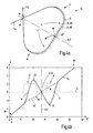
- the coordinates x and y are detected at the input 16 of the monochromator 1 and in the following representations the deflections A of the charge parts x ⁇ and y ⁇ to the optical axis E of the monochromator 1 shown.
- E ' is the respective location on the optical axis E, which corresponds to the abscissa in the diagrams 4b, 5b and 6b, on the ordinate, the deflection of the charged particles is plotted to the optical axis E.
- the path through the monochromator 1 would be exactly along its optical axis E.
- FIG. 12 shows an example of a course of a deflection path 14 of a monochromator 1 having a loop-shaped deflection path 14.
- Monochromators 1 have arcuate bends 14 to separate the charged particles of different energies. With such arcuate bends 14, faster, higher energy charged particles are carried outwardly and have an axis deviation d E - which is proportional to the energy deviation - from the axis E, as indicated by the dashed line E + d E for the strongest deviation. The reverse occurs with low energy charged particles following the dot-dash line E-dE.
- the axis deviation is proportional to the energy difference to the target energy.
- Fig. 4a only two deflecting elements 2 and 8 are used, wherein in the intermediate plane of symmetry 5 'of the monochromator 1, the selection aperture 6 is located.
- the plane 5 of the selection aperture 6 is here identical to the plane of symmetry 5 '.
- the illustration shows first the deflection elements 2 and 8 of the Fig. 4a corresponding deflection fields 2 'and 8'. Since these deflecting fields 2 'and 8' have asymmetrical fields 2 ', 8' with respect to the optical axis E in the x and y directions - only the strength of the dipole component ⁇ I can be seen here - the x ⁇ particles are deflected substantially differently like the y ⁇ particles.
- the x ⁇ particles are guided through the first deflection field 2 'by a zero crossing 11, so that there is a line focus or a line-shaped image of the radiation source 17 is formed.
- Fig. 5a and 5b show another example, which corresponds to the just described, but the difference is that the loop of the deflection path 14 of four deflection elements 2, 3, 8, 9 of the Fig. 5a consists.
- a fundamental trajectory of the particles x a and y ⁇ is effected in contrast to the above by four deflection fields 2 ', 3', 8 'and 9', said deflection fields 2 ', 3', 8 ', 9' the four deflection elements. 2 , 3, 8, 9 correspond. Otherwise, the above applies in a corresponding manner.
- the Fig. 6a and 6b show the course of the deflection path 14, the deflection fields 2 ', 3', 8 ', 9' and the deflections A for a monochromator 1, the deflection path 14 has the shape of a ⁇ .
- the principles apply as described above, with the difference that the deflecting elements 2 and 3 have deflection fields 2 'and 3' acting in opposite directions, so that in this area of the track - as in FIG Fig. 6a to see - in between comes to a merger of the dispersion 4 different energies.
- Fig. 7 a a section through the selection panel 6 with these exemplary focus 10, 10 'and 10 ", of course, energies between 10' and 10" impinge on the selection panel 6 and only the desired energy interval 7 is transmitted.
- the two cones show (because of the above Course of the particle flow, all cones shown have elliptical cross-sections) with the tips in the point focus 10, for example, the merger of all particles of the exact energy corresponding to the axis E.
- the representation must be supplemented by the fact that a stroke extending from the point focus 10 'to the point focus 10 "is filled with such point focuses of different energies
- Fig. 7a illustrates, where it is shown that the aperture 6 only the desired energy interval 7 passes.
- the aperture of the aperture 6 can have almost any desired shape, it is only necessary to clearly delimit the line between 10 'and 10 "to the energy interval 7, even if the exact position of the particle stream may have certain deviations Aperture useful.
- the Fig. 8 shows a slit 29 of the prementioned prior art to illustrate the differences. Since there are no point focuses 10, 10 ', 10 ", but line focusses 31, 31', 31" are imagined as nothing but parallel lines between the line focus 31 'of least energy and the line focus 31 "of the strongest energy must, it is here required that the desired energy interval 7 is hidden by a slit 29. Therefore, the problem in the manner described above is that such a slit 29 must have exact side boundaries 29 ', 29 ".
- Fig. 9 shows an embodiment of a deflection element 2, 3, 8 or 9 of the invention, wherein this consists of an inner electrode 24 and an outer electrode 25.
- the inner electrode 24 has frusto-conical surfaces 26, 26 'which are V-shaped and this "V" faces another "V” formed by the frusto-conical surfaces 27, 27' of the outer electrode 25.
- a rhomboid-shaped annular space (toroid - for calculation according to the SCOFF approximation) is formed which extends over the entire angular range of the arc angle ⁇ of the respective deflection element 2, 3, 8 or 9.
- the shielding plates which are arranged with a gap relative to the surfaces 36, 36 'of the deflecting elements 2, 3, 8, 9, which are aligned perpendicular to the axis E, ie to the deflection path 14.
- These shielding plates each have small holes in the region of the deflection path 14 as passage openings for the charged particle flow and are likewise at the extractor potential.
- These shielding plates can form box-shaped shields of the deflecting elements 2, 3, 8, 9 with the aforementioned plates.
- Fig. 9a shows a further embodiment of a deflecting 2, 3, 8 or 9, in which case the view perpendicular to the also in the Fig. 9 drawn surface 36 is directed.
- the surfaces 27, 27 'of the outer electrode 25 and the surfaces 26 and 26' of the inner electrode 24 are curved here.
- the x-, y- and z-axes of the curvilinear space coordinate system are shown, wherein the z-axis comes out perpendicular to the image plane and follows the course of the deflection path 14 here.
- the curved surfaces 26, 26 ', 27, 27' are symmetrical to the x-plane and always have the same distances and curvatures along the z-axis.
- the fact that the contour is deformed on the surface 36 'relative to the surface 36 comes only because the view of the surface 36 is perpendicular, the surface 36', however, extends obliquely backwards.
- Fig. 10a shows a schematic diagram of the cross section of a deflector 2, 3, 8, 9 with the formation of a hexapole.
- This cross section corresponds to the already in Fig. 9 cross section shown.
- the electrodes 24, 25 first form a dipole, which is sufficient to produce the desired deflection path 14. Only the required arcs have to be assembled with the corresponding bow angles ⁇ . However, such a composed of dipoles monochromator 1 would in turn generate image aberrations. These can be minimized by the use of multipole elements.
- Multipole elements in the sense used here are not pure multipole elements - if these are called those skilled in the art (see Kahl, supra) - but they are dipoles with an overlay by a multipole. Bending elements can be formed by their geometric shape to such superposed by multipoles dipoles.
- the Fig. 10a a schematic diagram of a possible geometric shape.
- a certain shaping of the equipotential lines 37, 37 ', 37 "occurs - According to the deflection path 14 - curved xz surface the zero potential 37 runs in the xy plane as a straight line through the electrodes 24, 25.
- Fig. 10b 2 shows another geometric shape of the surfaces 26, 26 ', 27, 27' of electrodes 24, 25. These have no symmetry with respect to the yz-section, whereby the equipotential line 37 of the extractor potential defined as zero potential is curved and also the other equipotential lines (FIG.
- the geometry shown by way of example can be used to form a dipole superimposed by a quadrupole, so that further variations of the different refractive powers in the xz and yz sections can be set Higher-order multipole elements possible if higher-order aberrations are to be corrected.
- the shapes of the deflection path 14 may also have other configurations, and it would of course also be possible to provide more than four deflection elements 2, 3, 8, 9.
- the shape of the electrodes 24 and 25 can be constructed in many different ways, instead of the surfaces 26, 26 ', 27, 27' could also find other various forms application. It is only important that they are far enough from the point symmetry of a spherical shape vary so that it does not come to point focuses within the deflection fields 2 ', 3', 8 ', 9'.
Landscapes
- Chemical & Material Sciences (AREA)
- Analytical Chemistry (AREA)
- Electron Tubes For Measurement (AREA)
Description
Die Erfindung betrifft einen Monochromator für eine Ladungsteilchenoptik, insbesondere für die Elektronenmikroskopie, mit mindestens einem ersten Ablenkelement mit einem elektrostatischen Ablenkfeld zur Erzeugung einer Dispersion in einer Ebene mit einer Selektionsblende zur Selektion der Ladungsteilchen des gewünschten Energieintervalls und mindestens einem zweiten Ablenkelement mit einem elektrostatischen Ablenkfeld, das die Dispersion des mindestens einen ersten Ablenkfeldes eliminiert.The invention relates to a monochromator for a charged particle optics, in particular for electron microscopy, with at least one first deflection element with an electrostatic deflection field for generating a dispersion in a plane with a selection aperture for selecting the charged particles of the desired energy interval and at least one second deflection element with an electrostatic deflection field. which eliminates the dispersion of the at least one first deflection field.
Chromatische Aberration ist einer der Hauptfaktoren, der durch die dadurch hervorgerufene Verbreiterung der Ladungsteilchenstrahlen aufgrund der Breite des Energiespektrums und des Farbfehlers der Linsen die Auflösung in der Ladungsteilchenoptik begrenzt. Der Zweck von Monochromatoren besteht darin, diese chromatische Aberration zu begrenzen. Beispielsweise darf in der Elektronenmikroskopie bei einer Beschleunigungsspannung von 200 kV die Energiebreite von 0,2 eV nicht überschritten werden, um eine Auflösung von weniger als 1 Angström zu erzielen. Als Elektronenquellen mit den geringsten Halbwertsbreiten gelten thermisch unterstützte Feldemissionskathoden, bei denen die Energiehalbwertsbreite jedoch immer noch 0,6 bis 1,0 eV beträgt. Untersuchungen haben gezeigt, daß etwas 30 % der Elektronen eine Abweichung von weniger als 0,1 eV besitzen. Für bestimmte Anwendungen, wie bei Transmissions- oder Rasterelektronenmikroskopen sind geringe Stromstärken ausreichend, so daß das Herausfiltern von ca. 70 % der Elektronen ein gangbarer Weg zur Realisierung einer hinreichend monochromatischen Elektronenquelle mit ausreichender Stromstärke darstellt. Daher können Monochromatoren zum Einsatz kommen.Chromatic aberration is one of the major factors limiting the resolution in the charged particle optics due to the broadening of the charged particle beams due to the width of the energy spectrum and the color aberration of the lenses. The purpose of monochromators is to limit this chromatic aberration. For example, in electron microscopy at an acceleration voltage of 200 kV, the energy width of 0.2 eV must not be exceeded in order to achieve a resolution of less than 1 angstrom. Thermally assisted field emission cathodes, in which the energy half-width is still 0.6 to 1.0 eV, apply as electron sources with the lowest half-widths. Studies have shown that some 30% of the electrons have a deviation of less than 0.1 eV. For certain applications, such as transmission or scanning electron microscopes low currents are sufficient, so that the filtering out of about 70% of the electrons is a viable way to realize a sufficiently monochromatic electron source with sufficient current. Therefore, monochromators can be used.
Im Gegensatz zu solchen durch Filterung mittels eines Monochromators erzielten monochromatischen Elektronenquellen gibt es auch noch abbildende Energiefilter zur Erzeugung eines achromatischen Bildes einer Probe. Ein solcher abbildender Energiefilter ist aus der
Aus der
Aus der
Bei derartigen Punktfokussierungen treffen sich jedoch nur Ladungsteilchen gleicher Energie in einem Punkt. Durch unterschiedliche Energien der Ladungsteilchen reihen sich die Punkte der Ladungsteilchen unterschiedlicher Energien aneinander und bilden so einen Strich, so daß es möglich ist, mit der Selektionsblende die Ladungsteilchen mit zu hoher und zu niedriger Energie abzuschirmen und nur Ladungsteilchen des gewünschten Energieintervalls durchzulassen. Dieses Energieintervall wird dann nach der Selektionsblende durch die nachgeschalteten Ablenkelemente wieder vereinigt; die Dispersion durch die vorgeschalteten Ablenkelemente wird also wieder eliminiert.In such point focusing, however, only charged particles of the same energy meet in one point. As a result of different energies of the charged particles, the points of the charged particles of different energies line up to form a line, so that it is possible to shield the charged particles with too high and too low energy with the selection aperture and to pass only charged particles of the desired energy interval. This energy interval is then reunited after the selection aperture by the downstream deflection elements; the dispersion by the upstream deflection is thus eliminated again.
Der Nachteil von Monochromatoren der oben beschriebenen Art mit punktförmigen Zwischenbildern der Strahlquelle besteht darin, daß sich Ladungsteilchen um so mehr gegenseitig beeinflussen, je enger sie zusammengeführt werden. Dieser Boersch-Effekt wirkt dem Bestreben, eine möglichst hohe Monochromasie zu erzielen, entgegen. Ladungsteilchen stoßen sich gegenseitig ab, so daß es zu Bremsungen und Beschleunigung mit einer zusätzlichen Dispersionswirkung kommt; man spricht davon, daß sich die virtuelle Quellgröße vergrößert. Ein Monochromator ist so aufgebaut, daß er in dem Teil, der nach der Selektionsblende liegt, die Dispersion des Teils, der vor der Selektionsblende liegt, wieder eliminiert. Er kann somit die Ortsveränderungen, die er durch seine Ablenkfelder herbeiführt, wieder rückgängig machen, jedoch nicht solche Ortsveränderungen, die durch die gegenseitige Beeinflussung der Ladungsteilchen herrühren. Diese beeinträchtigt die Monochromasie und somit die Fokussierbarkeit des Strahls, was dann wiederum die Auflösung der Optik beeinträchtigt.The disadvantage of monochromators of the type described above with punctiform intermediate images of the beam source is that charge particles influence each other the more closely they are brought together. This boer effect counteracts the desire to achieve the highest possible monochromaticity. Charge particles repel each other, so that it comes to braking and acceleration with an additional dispersion effect; It is said that the virtual source size increases. A monochromator is constructed so that in the part which lies after the selection aperture, the dispersion of the part which lies in front of the selection aperture is eliminated again. He can thus change the location he caused by its deflection fields, undo, but not such location changes, which result from the mutual influence of the charged particles. This affects the monochromatism and thus the focusability of the beam, which in turn affects the resolution of the optics.
Ausgehend vom vorgenannten und ähnlichen Monochromatoren mit Punktfokussierungen (stigmatische Zwischenbilder) wurde in der Dissertationsarbeit "Design eines Monochromators für Elektronenquellen" von Frank Kahl (http://elib.tu-darmstadt.de /diss/000030) ein Monochromator der eingangs genannten Art vorgeschlagen, bei dem die Ablenkelemente derart ausgebildet werden, daß die Ladungsteilchen eines x- und y-Schnittes unterschiedliche Bahnen beschreiben und daß mehrere Bilder einer Strahlquelle ausschließlich als astigmatische Zwischenbilder in Form von Linienfokussen auftreten. Dabei dient jedoch lediglich das dispersive astigmatische Bild in der Symmetrieebene zur Selektion der Ladungsteilchen des gewünschten Energieintervalls. Da dieses dispersive Bild astigmatisch ist, muß dazu eine Schlitzblende verwendet werden. Der vorgeschlagene Monochromator führte auch zum Patent
In dieser Dissertationsarbeit wurden bisher vorgeschlagene Monochromatoren unter 3.1 (Seiten 25 bis 27) vorgestellt, unter anderem der Monochromator von Rose (3.1.3), welcher dem der
Da alle vorbekannten Monochromatoren den nachteiligen Boersch-Effekt der Punktfokusse (stigmatische Zwischenbilder) aufweisen, mußte der Strahlstrom auf 10nA begrenzt werden (a.a.O., S. 28). Dies ist wiederum von Nachteil, da eine Steigerung der Auflösung große Beleuchtungsströme in Verbindung mit einer geringen Energiebreite der Quelle voraussetzt. Zur Überwindung dieser Beschränkung wurde vorgeschlagen, ausschließlich astigmatische reelle Zwischenbilder der Quelle zuzulassen (a.a.O. 3.2, Seite 28), also Linienfokusse. Linienfokus bedeutet, daß die Ladungsteilchen einer Energie in den Zwischenbildern die Strahlenquelle nicht als Punkt, sondern als Linie abgebildet werden. Diese Linienfokusse sind in einer Darstellung der Fundamentalbahnen der Abbildung 7.3, (a.a.O., Seite 85) enthalten.Since all previously known monochromators have the disadvantageous Boersch effect of the point focusses (stigmatic intermediate images), the beam current had to be limited to 10 nA (loc. Cit., P. 28). This in turn is disadvantageous since an increase in resolution requires large illumination currents in conjunction with a low energy source width. To overcome this limitation, it was proposed to allow only astigmatic real intermediate images of the source (a.a.O. 3.2, page 28), ie line foci. Line focus means that the charged particles of energy in the intermediate images are the source of the radiation, not as a point but as a line. These line foci are included in a representation of the fundamental orbits of Figure 7.3, (a.a.O., page 85).
Die Linienfokusse werden durch die verschiedenen Energien entsprechend der Dispersion verbreitert, so daß in der für die Selektion genutzten Fokusebene ein Strahl entsteht, der im Wesentlichen einen viereckigen Querschnitt aufweist. Um bei diesem Fokus ein gewünschtes Energieintervall zu selektieren, ist es erforderlich, Ladungsteilchen mit abweichenden Energien abzuschirmen und nur die Linienfokusse des gewünschten Energieintervalls durch die Blende zu lassen. Dazu ist wegen der Linienfokusse eine in deren Richtung ausgerichtete Schlitzblende erforderlich, deren Breite das ausgewählte Energieintervall bestimmt (siehe
Dieser Monochromator vermeidet zwar den starken Boersch-Effekt der stigmatischen Zwischenbilder, der Nachteil dieses Monochromators besteht jedoch darin, daß jede Unebenheit oder Verschmutzung des Schlitzes der Blende ebenfalls auf den Ladungsteilchenstrom wirkt, was zu Streuungen führt und sich im Endbild des optischen Systems als Intensitätsunterschiede auswirkt, die sich streifenförmig über das Bild ziehen (siehe
Ein solcher Monochromator ist auch aus der
Auch die
Das Dokument
Der Erfindung liegt daher die Aufgabe zugrunde, einen Monochromator der eingangs genannten Art derart auszugestalten, daß eine möglichst hohe Monochromasie ohne fehlerbedingte Intensitätskontraste erzielbar ist.The invention is therefore based on the object, a monochromator of the type mentioned in such a way that the highest possible monochromaticity without error-related intensity contrasts can be achieved.
Die Aufgabe wird erfindungsgemäß dadurch gelöst, daß die Ablenkelemente derart von einer sphärischen Form abweichend ausgebildet und ihre Elektroden mit einem derartigen Potential beaufschlagt sind, daß die axialen Fundamentalbahnen der Ladungsteilchen, die in verschiedenen Schnitten jeweils unter einem Winkel virtuell in ein stigmatisches Bild mit einem Nulldurchgang beider Fundamentalbahnen einer Strahlquelle einlaufen, derart unterschiedlich fokussiert werden, daß es ausschließlich in der Ebene der Selektionsblende zu einem stigmatischen Bild der Strahlquelle mit einer Punktfokussierung von Ladungsteilchen einer Energie kommt, da im gesamten Monochromator nur dort Nulldurchgänge der axialen Fundamentalbahnen der Ladungsteilchen der verschiedenen Schnitte bei der gleichen Achsposition aufeinandertreffen.The object is inventively achieved in that the deflection such deviates from a spherical shape and their electrodes are subjected to such a potential that the axial fundamental trajectories of the charged particles in different sections each at an angle virtually in a stigmatic image with a zero crossing Both fundamental paths of a beam source enter, are focused so differently that it comes exclusively in the plane of the selection aperture to a stigmatic image of the beam source with a point focusing of charged particles of energy, as there in the entire monochromator only there zero crossings of the axial fundamental trajectories of the charged particles of the various sections the same axis position meet.
Wie oben zur
Der Grundgedanke der Erfindung besteht darin, sowohl die oben beschriebenen Ablenkungen von Ladungsteilchen durch die Schlitzblende zu vermeiden, als auch die Verschlechterung der Monochromasie durch den Boersch-Effekt auf ein Minimum zu reduzieren. Um vom Einsatz einer Schlitzblende wegzukommen, mußte man Punktfokussierungen der verschiedenen Energien im Bereich der Selektionsblende erzeugen, so daß das gewünschte Energieintervall von den abweichenden Energien mittels einer Blende getrennt werden kann. Da der Ladungsteilchenstrom durch den Punktfokus im Bereich des Herausschneidens der abweichenden Energien nur eine ganz geringe Ausdehnung aufweist, kommen Unebenheiten und Verschmutzungen des Randes der zum Einsatz kommenden Blendenöffnung nicht zum Tragen. Jedoch mußte verhindert werden, daß es zu weiteren Punktfokussierungen kommt, damit der Boersch-Effekt der Punktfokussierung auf die einzige Punktfokussierung im Bereich der Selektionsblende beschränkt bleibt. Daher ist es nicht möglich, Kugelfelder, wie von der
Die Ablenkelemente müssen somit zwar, wie von Kahl (a.a.O.) vorgeschlagen, derart ausgebildet werden, daß sie Ladungsteilchen, die von der optischen Achse in verschiedenen Richtungen entfernt sind, sich also in verschiedenen Schnitten, wie beispielsweise im x-Schnitt oder im y-Schnitt, befinden, unterschiedlich ausgelenkt werden. Auf diese Weise lassen sich weitere Punktfokussierungen außerhalb des Bereichs der Selektionsblende dadurch vermeiden, daß die Ablenkungen der Ladungsteilchen, die in verschiedenen Schnitten liegen, also die Fundamentalbahnen xα und yβ, nicht gleichzeitig einen Nulldurchgang haben (siehe die Fundamentalbahndarstellung bei Kahl, a.a.O., Seite 85). Andererseits müssen jedoch die Ablenkelemente derart ausgestaltet und mit einem derartigen Potential beaufschlagt werden, daß es im gesamten Monochromator ausschließlich in der Ebene der Selektionsblende zu einem stigmatischen Bild der Strahlquelle mit einer Punktfokussierung von Ladungsteilchen einer Energie kommt. Dadurch wird es möglich, die Vorteile der Selektierung der unerwünschten Energien in einem Punktfokus beizubehalten, ohne die starke Vergrößerung der Quellfläche durch weitere Punktfokusse (stigmatische Zwischenbilder) herbeizuführen. Dies ermöglicht große Beleuchtungsströme in Verbindung mit einer geringen Energiebreite der Quelle und führt dadurch zu einer erheblichen Steigerung der Auflösung.Thus, as proposed by Kahl (supra), the baffles must be designed to be charged particles that are away from the optical axis in different directions, that is, in different cuts such as x-cut or y-cut , are, be differentially deflected. In this way, further point focussing outside the range of the selection aperture can be avoided in that the deflections of the charged particles lying in different sections, ie the fundamental orbits x α and y β , do not simultaneously have a zero crossing (see the fundamental trajectory in Kahl, loc. Page 85). On the other hand, however, the deflection elements must be designed and acted upon with such a potential that it comes in the entire monochromator exclusively in the plane of the selection aperture to a stigmatic image of the beam source with a point focusing of charged particles of energy. This makes it possible to retain the advantages of selecting the unwanted energies in a point focus, without causing the large enlargement of the source area by further point focusses (stigmatic intermediate images). This allows for large illumination currents in conjunction with a low energy source width, thereby resulting in a significant increase in resolution.
Die Geometrien und Potentiale der Ablenkelemente zur Erzielung der Ablenkbahnen mit einer einzigen Punktfokussierung in der Ebene der Selektionsblende sind auf verschiedenste Weisen möglich. Da es praktisch eine unendliche Vielzahl von Geometrien und Potentialen gibt, die dies bewirken können, muß der Fachmann sich seine gewünschte Lösung aus dieser Vielzahl von Möglichkeiten erarbeiten. Dies geschieht zum einen durch Festlegung auf bestimmte Parameter, die allgemein oder für die konkrete Teilchenoptik, beispielsweise das konkrete Elektronenmikroskop zweckmäßig sind. Dann kann eine Berechnung erfolgen, die die konkrete Form ergibt. Solche Berechnungen sind bekannt, beispielsweise aus der oben genannten Dissertation von Kahl (a.a.O.).The geometries and potentials of the deflection elements for achieving the deflection paths with a single point focus in the plane of the selection aperture are possible in many different ways. Since there is virtually an infinite variety of geometries and potentials that may effect this, one skilled in the art will have to work out his desired solution from this variety of possibilities. This is done on the one hand by fixing on certain parameters that are general or appropriate for the specific particle optics, for example the concrete electron microscope. Then a calculation can be made, which gives the concrete form. Such calculations are known, for example from the abovementioned dissertation by Kahl (loc. Cit.).
Zunächst ist es natürlich günstig, wenn auch die Anzahl der Strichfokusse minimal gehalten wird, da auch diese einen Boersch-Effekt aufweisen, wenn dieser auch wesentlich geringer ist, als bei einem Punktfokus.First, it is of course beneficial if the number of line focusses is kept to a minimum, since these also have a Boersch effect, although this is also much lower than with a point focus.
Es könnte also zweckmäßig sein, die Felder so auszugestalten, daß es außer den Nulldurchgängen der Ablenkungen der Ladungsteilchen verschiedener Schnitte in der Ebene der Selektionsblende zu keinen weiteren Fokussen im Monochromator kommt. Auf der anderen Seite ist es aber auch ein Ziel, eine breit auseinandergezogene Dispersion in der Selektionsblende zu erzielen, was bestimmte Bahnkrümmungen erforderlich macht und unter Umständen nur realisierbar ist, wenn man zumindest zwei Strichfokusse in einem Schnitt zuläßt.It may therefore be expedient to design the fields in such a way that, apart from the zero crossings of the deflections of the charged particles of different sections in the plane of the selection aperture, no further focussing takes place in the monochromator. On the other hand, it is also an aim to achieve a widely dispersed dispersion in the selection aperture, which makes certain path curvatures necessary and may only be feasible if at least two line focusses are allowed in one section.
Hier müssen also die Vor- und Nachteile für die konkrete Optik abgewogen werden unter der Bedingung, daß die Ablenkelemente so ausgestaltet werden müssen, daß sich die Nulldurchgänge der Amplituden von Ladungsteilchen verschiedener Schnitte ausschließlich im Bereich der Selektionsblende treffen. Eine zweckmäßige Ausgestaltung sieht vor, daß die Ablenkelemente derart ausgebildet sind, daß die Ablenkfelder Umkehrpunkte in der Ablenkung der Ladungsteilchen eines Schnitts (x-Richtung) mit dazwischen liegenden Nulldurchgängen durch die Achse der Ablenkbahn verursachen, jedoch bei Ladungsteilchen eines senkrecht dazu ausgerichteten Schnitts (y-Richtung) lediglich Änderungen der Bahnkrümmungen mit einem einzigen Nulldurchgang durch die optische Achse im Bereich der Selektionsblende auftritt. Treten Nulldurchgänge nur in der x- oder y-Richtung auf, so kommt es lediglich zu Strichfokussierungen, die einen wesentlich geringeren Boersch-Effekt aufweisen.Here, therefore, the advantages and disadvantages of the concrete optics must be weighed under the condition that the deflection must be designed so that meet the zero crossings of the amplitudes of charged particles of different sections exclusively in the field of selection. An expedient embodiment provides that the deflection elements are designed such that the deflection fields cause reversal points in the deflection of the charged particles of a section (x-direction) with intermediate zero crossings through the axis of the deflection path, but with charged particles of a section (y Direction) only changes of the path curvatures with a single zero crossing through the optical axis in the region of the selection aperture occurs. If zero crossings occur only in the x or y direction, then only line focussing results, which have a substantially lower Boersch effect.
Daß hier die Ladungsteilchen der Schnitte in x- und y-Richtung, also die Fundamentalbahnen xα und yβ, angegeben sind, dient natürlich nur der Beschreibung der Verformung des Strahlenbündels durch die elektrischen Felder. Tatsächlich ist der gesamte Strahlenquerschnitt der x-y-Ebene mit Ladungsteilchen gefüllt und alle nehmen an Verformungen des Strahlenquerschnitts teil, so daß der gesamte Strahl auch mit den Ladungsteilchen, bei denen α und β zwischen Null und einem Maximalwert liegen, im Strichfokus zu einem Strich in x- oder y-Richtung und im Punktfokus zu einem Punkt gebündelt wird. Der Teilchenstrom bildet also außer in der Selektionsblende (Punktfokus) wechselweise Striche - soweit Strichfokusse zugelassen sind - die sich in x- oder y-Richtung erstrecken und dazwischen bildet er Ellipsen, die ihrer Länge nach abwechselnd in der einen oder anderen Richtung liegen, und als Übergang dazwischen Kreise. Die Strichfokusse sind dann Nulldurchgänge für die Ladungsteilchen des x- oder y-Schnitts und im Punktfokus sind Nulldurchgänge für alle Schnitte.The fact that the charged particles of the sections in the x and y directions, ie the fundamental orbits x α and y β , are given here, of course only serves to describe the deformation of the beam by the electric fields. In fact, the entire beam cross-section of the xy plane is filled with charged particles and all participate in deformations of the beam cross section, so that the entire beam also with the charged particles, where α and β are between zero and a maximum value Line focus is focused to a stroke in the x or y direction and in the point focus to a point. The particle flow forms except in the selection aperture (point focus) alternately strokes - as far as line foci are allowed - which extend in the x or y direction and in between it forms ellipses, which lie alternately in their length in one or the other direction, and as Transition between circles. The dashed foci are then zero crossings for the charged particles of the x or y-cut and in the point focus are zero crossings for all cuts.
Der erfindungsgemäße Monochromator hat seine Vorzüge sowohl für Rasterelektronenmikroskope als auch für Ruhbildelektronenmikroskope. Es kann die Rasterfunktion verbessert werden, da durch die Monochromasie ein kleinerer Spot (Bildpunkt) erzielbar ist. Für die Ruhbildabbildung können die Intensitätskontraste der einen Linienfokus begrenzenden Schlitzblende (siehe oben, Würdigung der
Um die Ablenkfelder zu erzeugen, sind Ablenkelemente mit in ein oder zwei Dimensionen gekrümmte Flächen vorgesehen. Diese schließen bogenförmige Bahnen ein, die, wenn die Ladungsteilchen Elektronen oder negativ geladene Ionen sind, an der Innenseite eine positive und an der Außenseite eine negative Spannung gegenüber dem Achspotential aufweisen, um die Ladungsteilchen auf dieser Bahn zu führen. Um Ladungsteilchen verschiedener Schnitte unterschiedlich zu beeinflussen, müssen Felder erzeugt werden, die vom Kugelfeld unterschiedlich sind. Dazu dienen Elektroden mit Ablenkfeldern die bezüglich der Ablenkbahn asymmetrisch sind, also in x- und in y-Richtung verschiedene Stärken aufweisen. Dabei sind die Verhältnisse bezüglich der x-Ebene, in der die gekrümmte optische Achse verläuft, bezüglich Geometrie und Potentialverläufen symmetrisch, so daß die Bahn in dieser Symmetrieebene bleibt.To create the deflection fields, baffles are provided with surfaces curved in one or two dimensions. These include arcuate paths which, when the charged particles are electrons or negatively charged ions, have a positive voltage on the inside and a negative voltage on the outside of the axis potential to guide the charged particles on that track. In order to influence charge particles of different cuts differently, fields must be generated that are different from the ball field. For this serve electrodes with deflection fields which are asymmetrical with respect to the deflection path, ie have different strengths in the x and y directions. The relationships with respect to the x-plane, in which the curved optical axis extends, are symmetrical with respect to geometry and potential profiles, so that the web remains in this plane of symmetry.
Der Weg des Fachmanns zum Auffinden einer bestimmten Lösung kann beispielsweise in der Art erfolgen, wie dies bei Kahl (a.a.O.) beschrieben ist, jedoch selbstverständlich unter der Vorgabe, daß ein stigmatisches Zwischenbild der Quelle (Punktfokus) in der Selektionsblende liegen muß. Es müssen also die Berechnungsgrundlagen insofern abgeändert werden.The way of the skilled person to find a particular solution can be done, for example, in the manner described in Kahl (loc. Cit.), But of course under the requirement that a stigmatic intermediate image of the source (point focus) must be in the selection aperture. So the calculation bases have to be changed in this respect.
Der prinzipielle Weg des Fachmanns wird jedoch hier unter Verweis auf Kahl (a.a.O.) kurz skizziert. Zunächst muß der Fachmann die Form der Achse E des Monochromators wählen. Er entscheidet sich beispielsweise für die Ω -Form, um eine - abgesehen von der Unterbrechung durch den Monochromator - gerade optische Achse der Ladungstteilchenoptik, beispielsweise des Elektronenmikroskops, zu erzielen. Bildet er das Ω relativ steil aus, so daß Ein- und Ausgang nahe zusammenrücken, erhält er eine geringe Bauhöhe, was ebenfalls erstrebenswert ist. Der Fachmann wird gleiche Spannungen für die Elektroden der Ablenkelemente wählen, da dies die Betriebsstabilität erhöht, weil die Spannungen der Ablenkelemente nicht gegeneinander schwanken können. Weiterhin wird er eine möglichst große Dispersion im Punktfokus wählen, damit die Selektion der gewünschten Energie exakt vorgenommen werden kann.However, the basic route of the person skilled in the art is briefly outlined here with reference to Kahl (loc. Cit.). First, the person skilled in the art must choose the shape of the axis E of the monochromator. It decides, for example, for the Ω-shape to a - apart from the interruption by the monochromator - straight optical axis of Charge particle appearance, for example, the electron microscope to achieve. If he forms the Ω relatively steeply, so that the input and output close together, he receives a low overall height, which is also worth striving. The person skilled in the art will select equal voltages for the electrodes of the deflection elements, since this increases the operational stability because the voltages of the deflection elements can not fluctuate with respect to one another. Furthermore, he will choose the largest possible dispersion in the point focus, so that the selection of the desired energy can be made exactly.
Der erste Schritt wird dann sein, unter diesen Prämissen die Krümmungen der optischen Achse, beispielsweise die α- oder aus den oben genannten Gründen die Ω -Form auszuwählen. Dabei wird die Krümmung der Achse allein durch die elektrischen Dipole der Elektroden der Ablenkelemente bestimmt. Zur Berechnung der Fundamentalbahnen der Ladungsteilchen dient ein orthogonales Koordinatensystem mit einer z-Achse, die der Achse E des Monochromators entspricht, also krummlinig ist. In dieses Koordinatensystem werden die Ablenkelemente eingefügt, die als Abschnitte von Toroiden ausgebildet sind, damit diese Formen einer Näherungsrechnung zugrundegelegt werden können. Es handelt sich um eine Berechnung nach der SCOFF-Nährung (Sharp-Cut-Off Fringe Field-Nährung) zur Berechnung der konkreten Geometrie, wie bei Kahl (a.a.O.) Kapitel 5, Seite 57 ff. offenbart. Dabei wird eine Fundamentalbahnberechnung (a.a.O., 4.4.2, S. 44 ff.) zugrundegelegt, die die hier gestellten Bedingungen an die Fokusse enthält. Die konkreten Ausgestaltungen der Flächen der Elektroden verlaufen in dem orthogonalen Koordinatensystem symmetrisch zum xz-Schnitt. Auf jeden Fall weisen die Flächen der Toroide für jeden Ort auf der z-Achse dieselben Abstände auf, so daß das Toroid für die Berechnung der SCOFF-Näherung als geometrische Figur zur Verfügung steht. Unter Toroid wird hier eine Kreisringform jeglichen Querschnitts der beanspruchten Art verstanden. Vorzugsweise bilden die Flächen, zwischen denen die Ablenkbahn verläuft, keine Zylinderflächen in y-Richtung. Dadurch können den Dipolen Multipole überlagert werden, da das jeweilige Potential erhöht wird, wenn die Elektrode an einer Stelle in der x-y-Ebene geometrisch näher an die optische Achse herankommt, und umgekehrt erniedrigt wird, wenn sie weiter entfernt ist. Der Zweck besteht darin, daß durch diese Ausgestaltung der Ablenkfelder den durch den Monochromator verursachten Öffnungsfehlern entgegengewirkt werden kann. Bei den Multipolen kann es sich um Quadrupole, Hexapole oder höherzahlige Multipole handeln, wobei die letzteren dazu dienen, auch Öffnungsfehler dritter oder höherer Ordnung zu minimieren. Bezüglich der Berechnung der Elektrodenform wird auf Kahl (a.a.O., 5.3, S. 61 ff; 8.5, S. 94 ff und S. 125, 126) verwiesen.The first step will then be to select the curvatures of the optical axis, for example the α- or for the reasons mentioned above, the Ω-shape under these premises. The curvature of the axis is determined solely by the electric dipoles of the electrodes of the deflection elements. For calculating the fundamental orbits of the charged particles, an orthogonal coordinate system with a z-axis, which corresponds to the axis E of the monochromator, is curvilinear. In this coordinate system, the baffles are inserted, which are designed as sections of toroids, so that these forms can be based on an approximate calculation. It is a calculation according to the SCOFF diet (Sharp-Cut-Off Fringe Field Nutrition) for the calculation of the concrete geometry, as disclosed in Kahl (loc. Cit.)
Die Berechnung der konkreten Form, einschließlich der Berücksichtigung der Randbereiche der toroidförmig durch die Elektroden begrenzten Ablenkbahnen für den Aufbau der Ablenkfelder findet durch Triangulierung (a.a.O., 9.1, S. 99 ff) und ein Iterationsverfahren statt (Kahl, a.a.O., 9.3.9.4 und 9.5, S. 108ff).The calculation of the concrete shape, including the consideration of the edge regions of the deflecting paths toroidally bounded by the electrodes for the construction of the deflection fields takes place by triangulation (loc. Cit., 9.1, p. 99 ff) and an iteration method (Kahl, loc. Cit., 9.3.9.4 and 9.5 , Pp. 108ff).
Die folgende Tabelle gibt eine bevorzugte Parameterwahl für ein System an, bei dem die Dipolfelder durch Quadrupolfelder überlagert sind:
![]()
![]()
![]()
![]()
Dabei ist:
-

- R gibt an, daß die Längen in Einheiten des Krümmungsradiusses des 1. Ablenkelements gemessen werden.
- R2 der Krümmungsradius des 2. Ablenkers
- Φ1 die Feldstärke des Dipolfeldes
- Φ2 die Feldstärke des Quadrupolfeldes
- U die Potentialdifferenz zwischen Kathode und der Achse - vorzugsweise im ganzen Monochromator konstant.
-
- R indicates that the lengths are measured in units of the radius of curvature of the 1st deflector.
- R 2 is the radius of curvature of the second deflector
- Φ 1 is the field strength of the dipole field
- Φ 2 is the field strength of the quadrupole field
- U the potential difference between the cathode and the axis - preferably constant throughout the monochromator.
Durch die Wahl der Stärke der Feldkomponenten Φ1 (Dipol) und Φ2 (Quadrupol), der Bogenradien und Bogenwinkel der Ablenkelemente und damit der Bogenlänge der Ablenkelemente und der feldfreien Zwischenräume lassen sich die Bahnen gezielt beeinflussen. Insgesamt ergibt sich eine Anzahl von Freiheitsgraden des Monochromators, denen Forderungen gegenüberstehen, etwa wo Fokusse entstehen sollen und daß das System am Ende dispersionsfrei wird. Wählt man etwa die Dipolund Qadrupolstärken in einem Ablenker ungefähr konstant, so ergeben sich etwa die Freiheitsgrade der o.g. Tabelle. Aus den Feldkomponenten Φ1 und Φ2 (und eventuell gewählten weiteren) ergeben sich die Elektrodenoberflächen der Ablenkelemente durch Aufsuchen der Flächen ϕ = const. Entsprechend Gleichung (5.4), S. 61 Diss. Kahl (a.a.O.) auf beiden Seiten der Achse für ϕ+ > U und ϕ- < U. Diese elektrostatischen Potentiale ϕ+ und ϕ- müssen dann an die metallischen Ablenkelemente gebracht werden.By choosing the strength of the field components Φ 1 (dipole) and Φ 2 (quadrupole), the radii of curvature and the arc angle of the deflection and thus the arc length of the deflection and the field-free spaces, the tracks can be selectively influenced. Overall, there are a number of degrees of freedom of the monochromator, which are faced with demands, such as where foci are to arise and that the system is free of dispersion at the end. If one chooses about the dipole and Qadrupolstärken in a deflector approximately constant, the result is about the degrees of freedom of the above table. From the field components Φ 1 and Φ 2 (and possibly selected further), the electrode surfaces of the deflection elements result by finding the surfaces φ = const. According to equation (5.4), p. 61 Diss. Kahl (loc. Cit.) On both sides of the axis for φ +> U and φ- <U. These electrostatic potentials φ + and φ- must then be brought to the metallic deflection elements.
Bei einem Hexapol zur Kompensation eines Öffnungsfehlers zweiter Ordnung muß eine weitere Feldkomponente Φ3 in die Berechnung einbezogen werden.For a hexapole to compensate for a second-order aperture error, another field component Φ 3 must be included in the calculation.
Die nach der o.g. Methode aufgefundenen Flächen der Elektroden können unterschiedlich geformte Flächen sein. Voraussetzung ist lediglich, daß es keine Kugelflächen sind, da mit diesen immer mehrere Punktfokussierungen entstehen. Bei Flächen, die von einer Kugelsymmetrie weit genug entfernt sind, treten Strichfokussierungen auf. Vorzugsweise sind die Flächen in y-Richtung gekrümmt, aber zur xz-Ebene spiegelsymmetrisch. Zweckmäßigerweise werden dabei die Elektroden der Ablenkelemente derart geformt, daß sie die Ablenkbahnen durch Flächen begrenzen, die Ausschnitte aus einer Kegelstumpfmantelfläche sind. Dabei können diese Flächen zwei "V" bilden, die mit den Spitzen in die gleiche Richtung weisen. Dazwischen verläuft dann die Ablenkbahn. Eine weitere Möglichkeit besteht darin, daß die Flächen, die zwei "V" bilden, die mit den Öffnungen zueinander weisen. Dann umschließen sie die in ihrer Mitte liegende Ablenkbahn. Neben der Erzielung der gewünschten Funktion, daß - mit Ausnahme des Bereichs der Selektionsblende - nur Strichfokussierungen entstehen, haben die vorgenannten Ablenkelemente den Vorteil, daß sie leicht herstellbar sind, da die Flächen durch Rotation gerader Linien um eine Achse gebildet werden. Solche Flächen sind ohne weiteres durch eine Rotation um die Achse der Kegelstümpfe mittels Drehautomaten, Rundschleifmaschinen und ähnlichem durch einen geradlinigen Werkzeugvorschub herstellbar, und das Arbeitsergebnis läßt sich auch auf einfache Weise durch Meßtaster oder optische Flächenerfassung überprüfen. Entsprechendes gilt für die äußeren Elektroden, die dann Flächen bilden, die von außen einen gedachten Kegelstumpf begrenzen und in entsprechender Weise mit einem Werkzeug von innen bearbeitet werden, z. B. als aufgespannte Napfform, aus der nach Beendigung der Dreh- und eventueller Schleifarbeiten die jeweilige Elektrode ausgeschnitten wird.The surfaces of the electrodes found by the above method can be differently shaped surfaces. The only prerequisite is that there are no spherical surfaces, as these always create multiple point focuses. For areas that are far enough away from spherical symmetry, line focussing occurs. Preferably, the surfaces are curved in the y-direction, but mirror-symmetrical to the xz-plane. The electrodes of the deflection elements are expediently shaped in such a way that they delimit the deflection paths by surfaces which are cutouts from a truncated cone lateral surface. These surfaces can form two "V" points with the tips in the same direction. In between then runs the deflection path. Another possibility is that the surfaces forming two "V's" facing each other with the openings. Then they enclose the deflection path in their midst. In addition to achieving the desired function that - except for the area of the selection aperture - only line focussing arise, the aforementioned baffles have the advantage that they are easy to produce, since the surfaces are formed by rotation of straight lines around an axis. Such surfaces are readily produced by a rotation about the axis of the truncated cones by means of automatic lathes, cylindrical grinding machines and the like by a linear tool feed, and the work result can also be checked in a simple manner by probe or optical surface detection. The same applies to the outer electrodes, which then form surfaces that limit an imaginary truncated cone from the outside and are processed in a corresponding manner with a tool from the inside, z. B. as a clamped cup shape from which the respective electrode is cut after completion of the rotation and any grinding.
Vorzugsweise ist der Monochromator um eine Ebene symmetrisch aufgebaut, wobei die Symmetrieebene der Ebene der Selektionsblende entspricht. Dabei führt auch eine spiegelbildliche Anordnung der Ablenkelemente dazu, daß auf die Ladungsteilchen nach der Selektionsblende die gleichen Kräfte wirken wie vor der Selektionsblende, nur entgegengesetzt gerichtet. Auf diese Weise wird die Dispersion der Ladungsteilchen des selektierten Strahls nach der Herbeiführung der Dispersion durch das oder die ersten Ablenkelemente wieder vollständig beseitigt.Preferably, the monochromator is constructed symmetrically about a plane, the plane of symmetry corresponding to the plane of the selection aperture. In this case, a mirror-image arrangement of the deflecting leads to the fact that the same forces act on the charged particles after the selection aperture as before the selection aperture, only oppositely directed. In this way, the dispersion of the charged particles of the selected beam is completely removed again after the dispersion has been brought about by the first deflecting element (s).
Der Monochromator kann - wie oben schon angesprochen - bezüglich seiner optischen Achse eine Vielzahl von Formen aufweisen, die Ausführungsbeispiele der Zeichnung geben dies beispielhaft an. Sie kann im Wesentlichen die Form einer Schlaufe haben, wobei bei dieser Ausgestaltung die Achsen bei einem Schließen der Schlaufe nicht völlig ineinander laufen dürfen, da sonst der Weg der Teilchen nicht mehr eindeutig bestimmt ist. Daher muß es sich entweder um eine offene Schlaufe oder eine Schlaufe mit seitlichem Versatz der Eingangs- zur Ausgangsachse handeln oder die Eingangsund die Ausgangsachse müssen sich überkreuzen. Denkbar wäre natürlich auch, daß ein Ineinanderlaufen dadurch vermieden wird, daß die optische Achse nicht ganz exakt in der x-Ebene bleibt (abweichend zur o.g. Symmetrieebene, in der die optische Achse liegen soll).The monochromator can - as already mentioned above - with respect to its optical axis have a variety of forms, the embodiments of the drawing indicate this by way of example. It may essentially have the shape of a loop, in which case the axes must not run completely together when the loop is closed, since otherwise the path of the particles is no longer uniquely determined. Therefore, it must either be an open loop or a loop with a lateral offset of the input to the output axis, or the input and output axes must cross each other. It would also be conceivable, of course, that one Running into one another is avoided by the fact that the optical axis does not remain exactly exactly in the x-plane (deviating from the above-mentioned symmetry plane in which the optical axis should lie).
Besonders zweckmäßig ist jedoch ein Monochromator, bei dem die optische Achse am Ausgang des Monochromators mit der optischen Achse am Eingang des Monochromators - das ist in der Regel die Verlängerung der optischen Achse der Strahlquelle - übereinstimmt. Dies ist erzielbar, wenn die optische Achse des Monochromators im Wesentlichen die Form eines Ω aufweist, wobei die Bogenelemente des Ω sowohl als starke Bögen wie auch als kurze und flache Bögen ausgebildet sein können. Dabei wird die Ω-Form durch zwei bogenförmige Ablenkelemente vor der Selektionsblende und zwei bogenförmige Ablenkelemente nach der Selektionsblende gebildet. Die kreisbogenförmigen Ablenkbahnen der Ablenkelemente weisen dabei vorzugsweise einen Bogenwinkel zwischen 120° und 150° auf, wie dies bereits die obige Tabelle angibt.Particularly useful, however, is a monochromator in which the optical axis at the output of the monochromator with the optical axis at the input of the monochromator - which is usually the extension of the optical axis of the beam source - matches. This can be achieved if the optical axis of the monochromator has substantially the shape of a Ω, wherein the arc elements of the Ω can be formed both as strong arcs and as short and flat arcs. The Ω-shape is formed by two arcuate deflection elements in front of the selection aperture and two arcuate deflection elements after the selection aperture. The circular arc-shaped deflection paths of the deflection elements preferably have an arc angle between 120 ° and 150 °, as already indicated by the above table.
Ein besonderer Vorzug dieser Ω-Form besteht darin, daß es möglich ist, daß das Eingangs- und das Ausgangsablenkelement mit einem Strahldurchtritt auszustatten, so daß beim Ausschalten des Monochromators die Ladungsteilchen geradlinig die Strahldurchtritte passieren können und sich damit entlang der optischen Achse zum Ausgang des Monochromators bewegen. Auf diese Weise kann die Bildgebung mit oder ohne Monochromator erfolgen. Dabei ist es besonders zweckmäßig, wenn der virtuelle Eingangs-Crossover und der virtuelle Ausgangs-Crossover des Monochromators in dessen Symmetrieebene zusammenfallen. Dadurch bleibt der Strahlengang auch beim Ausschalten des Monochromators erhalten. Auf diese Weise kann er ein- und ausgeschaltet werden, ohne daß jeweils eine neue Justierung des Strahlengangs vorgenommen werden muß.A particular advantage of this Ω-shape is that it is possible to provide the input and the output deflector with a beam passage so that when the monochromator is turned off, the charged particles can pass straight through the beam passages and thus along the optical axis to the output of the Move monochromators. In this way, the imaging can be done with or without monochromator. It is particularly expedient if the virtual input crossover and the virtual output crossover of the monochromator coincide in its plane of symmetry. As a result, the beam path is maintained even when the monochromator is switched off. In this way it can be switched on and off without having to make a new adjustment of the beam path in each case.
Eine Weiterbildung sieht vor, daß die Elektroden außen mit parallel zur optischen Achse ausgerichteten Platten auf Nullpotential abgeschirmt sind. Weiterhin können senkrecht zur optischen Achse beidseitig der Ablenkelemente, also am Ein- und Ausgang, Abschirmplatten auf Extraktorpotential angebracht sein, die eine kleine Bohrung als Durchtrittsöffnungen für den Strahldurchtritt enthalten. Dadurch wird das Ablenkfeld definiert begrenzt und ist unabhängig von weiteren potentialführenden Teilen in der Umgebung des Aufbaus. Dies dient einer Beherrschbarkeit und Berechenbarkeit der Randfelder der toroidförmigen Ablenkelemente. Es kann auch vorgesehen sein, daß die Elektroden kastenförmige Abschirmungen auf Extraktorpotential mit Durchtrittsöffnungen für den Ladungsteilchenstrom aufweisen.A further development provides that the electrodes are shielded on the outside with aligned parallel to the optical axis plates to zero potential. Furthermore, perpendicular to the optical axis on both sides of the deflection, ie at the input and output, shielding plates can be attached to extractor potential, which has a small Bore as passage openings for the jet passage included. As a result, the deflection field is defined limited and is independent of other potential-carrying parts in the vicinity of the structure. This serves to control and predict the edge fields of the toroidal deflection elements. It can also be provided that the electrodes have box-shaped shields at the extractor potential with openings for the flow of the charged particles.
Ein weiterer Gegenstand der Erfindung ist eine Strahlquelle mit einem Monochromator der vorgenannten Art, wobei dem Monochromator eine als Extraktor ausgebildete Strahlquelle mit einer elektrostatischen Linse und einer kreisförmigen Blende zur Regulierung und Begrenzung des Teilchenstroms vorgeordnet ist, wobei die Linse ein virtuelles Bild der Strahlquelle bildet, da dieses hinter dem Eingang des Monochromators liegt. Auf diese Weise läßt sich die dem Monochromator zugeführte Ladungsteilchenausbeute verbessern.Another object of the invention is a beam source with a monochromator of the aforementioned type, wherein the monochromator is formed as a trained extractor beam source with an electrostatic lens and a circular aperture for regulating and limiting the particle flow, wherein the lens forms a virtual image of the beam source, because this is behind the entrance of the monochromator. In this way, the charged particle yield supplied to the monochromator can be improved.
Nachfolgend wird die Erfindung anhand der Zeichnung erläutert. Es zeigen:
- Fig. 1
- eine Prinzipskizze einer einfach aufgebauten Ausführungsform der Erfindung,
- Fig. 2
- eine bevorzugte Ausführungsform,
- Fig. 3
- ein Ladungsteilchenstrahl am Eingang des Monochromators,
- Fig. 4a
- ein Beispiel eines Verlaufs der Ablenkbahn eines Monochromators,
- Fig. 4b
- die Ablenkfelder und die Auslenkungen der Ladungsteilchen xα und yβ gegenüber der Achse,
- Fig. 5a, 5b
- ein weiteres Beispiel,
- Fig. 6a, 6b
- dasselbe für die Ausführungsform gem.
Fig. 2 , - Fig. 7
- ein Schnitt durch die Selektionsblende mit beispielhaften Fokussen verschiedener Energiebereiche,
- Fig. 7a
- die Selektionsblende in Draufsicht,
- Fig. 8
- eine Schlitzblende des Standes der Technik,
- Fig. 8a
- die Intensitätsverteilung der Stromdichte über das Bild und
- Fig. 8b
- streifenförmige Intensitätsunterschiede im Bild beim Einsatz einer Schlitzblende,
- Fig. 9
- eine Ausführungsform eines Ablenkelements der Erfindung und
- Fig. 9a
- eine weitere Ausführungsform,
- Fig. 10a
- eine Prinzipskizze des Querschnitts eines Ablenkelements mit Bildung eines Hexapols und
- Fig. 10b
- mit Bildung eines Quadrupols.
- Fig. 1
- a schematic diagram of a simply constructed embodiment of the invention,
- Fig. 2
- a preferred embodiment,
- Fig. 3
- a charged particle beam at the entrance of the monochromator,
- Fig. 4a
- an example of a course of the deflection path of a monochromator,
- Fig. 4b
- the deflection fields and the deflections of the charged particles x α and y β with respect to the axis,
- Fig. 5a, 5b
- another example,
- Fig. 6a, 6b
- the same for the embodiment.
Fig. 2 . - Fig. 7
- a section through the selection aperture with exemplary foci of different energy ranges,
- Fig. 7a
- the selection panel in plan view,
- Fig. 8
- a slit diaphragm of the prior art,
- Fig. 8a
- the intensity distribution of the current density over the picture and
- Fig. 8b
- strip-shaped intensity differences in the image when using a slit diaphragm,
- Fig. 9
- an embodiment of a deflecting element of the invention and
- Fig. 9a
- another embodiment,
- Fig. 10a
- a schematic diagram of the cross section of a deflecting element with formation of a hexapole and
- Fig. 10b
- with formation of a quadrupole.
Bei allen Darstellungen zeigen gleiche Bezugszeichen funktionsidentische Bauelemente oder Kurvenverläufe. Die jeweils getroffenenIn all representations, like reference numerals indicate functionally identical components or curves. The respectively met
Der durch die Linse 21 und die Blende 22 regulierte und begrenzte Teilchenstrom 23' trifft auf den Eingang 16 des Monochromators 1. Dieser Monochromator 1 verfügt über vier Ablenkelemente, wobei zwei Ablenkelemente 2, 3 vor der Selektionsblende 6 und zwei weitere Ablenkelemente 8, 9 nach der Selektionsblende 6 angeordnet sind. Dabei ist dieser Monchromator 1 derart aufgebaut, daß die optische Achse E die Form eines Ω beschreibt. Die bogenförmigen Bahnen beschreiben Bögen im Bereich zwischen 120° und 150°, da die Ablenkelemente 2, 3, 8, 9 entsprechende Winkel θ aufweisen. Die Ebene 5 der Selektionsblende 6 ist dabei die Symmetrieebene 5' des Monochromators 1.The regulated by the
Um beim Ausschalten des Monochromators 1 ebenfalls noch eine Bildgebung erzielen zu können, ist der Monochromator 1 so aufgebaut, daß die optische Achse Es am Eingang 16 des Monochromators 1 exakt in die gleiche Richtung verläuft wie die optische Achse EA am Ausgang 16' des Monochromators 1. Entlang dieser Verbindungslinie sind das Ablenkelement 2 und das Ablenkelement 8 mit Strahldurchtritten 18 ausgestattet, so daß nach einem Abschalten des Monochromators 1 der Strahl unter Umgehung des Monochromators 1 direkt vom Eingang 16 zum Ausgang 16' weitergeleitet wird.In order to also be able to achieve imaging when the
Dabei wird zweckmäßigerweise der Strahlengang derart ausgestaltet, daß der virtuelle Eingangs-Crossover 19 und der virtuelle Ausgangs-Crossover 20 des Monochromators 1 in dessen Symmetrieebene 5' zusammenfallen. Auf diese Weise wird der gleiche Verlauf des Strahlengangs erzielt, unabhängig davon, ob der Monochromator 1 ein-oder ausgeschaltet ist. Der einzige Unterschied besteht natürlich darin, daß bei ausgeschaltetem Monochromator 1 nicht dieselbe Monochromasie erzielt wird. Durch diese Ausgestaltung bleibt somit beim Ausschalten des Monochromators 1 das Bild vollständig erhalten und am selben Ort, lediglich mit geringerer Auflösung durch den Wegfall der Funktion des Monochromators 1.In this case, the beam path is expediently designed such that the virtual input crossover 19 and the
Die
Bei der Darstellung der
Im Gegensatz zum Verlauf der Dispersion 4 und deren Eliminierung 4' zeigt
Die Darstellung zeigt zunächst die den Ablenkelementen 2 und 8 der
Die
In entsprechender Weise zeigt die
Die
Diese verschieden gerichteten Ablenkfelder 2', 3', 8' und 9' sind auch in
In entsprechender Weise zeigt die
Die
Diese Seitenbegrenzungen 29', 29"sind in
Als Beispiel für einen auf diese Weise geschaffenen Hexapol zeigt die
Selbstverständlich können die Zeichnungen nur einen kleinen Ausschnitt dessen wiedergeben, wie die Erfindung realisierbar ist. So können die Formen der Ablenkbahn 14 auch andere Ausgestaltungen aufweisen und es wäre selbstverständlich auch möglich, mehr als vier Ablenkelemente 2, 3, 8, 9 vorzusehen. Ebenso kann die Form der Elektroden 24 und 25 in verschiedenster Weise aufgebaut werden, statt der Flächen 26, 26', 27, 27' könnten auch sonstige verschiedenste Formen Anwendung finden. Wesentlich ist lediglich, daß sie weit genug von der Punktsymmetrie einer Kugelform abweichen, damit es nicht zu Punktfokussen innerhalb der Ablenkfelder 2', 3', 8', 9' kommt.Of course, the drawings can only reproduce a small portion of how the invention can be realized. Thus, the shapes of the
- 11
- Monochromatormonochromator
- 2, 32, 3
- Ablenkelementedeflectors
- 2', 3'2 ', 3'
- Ablenkfelderdeflection
- 44
- Dispersiondispersion
- 4'4 '
- Eliminierung der DispersionElimination of the dispersion
- 55
- Ebene der SelektionsblendeLevel of selection panel
- 5'5 '
- Symmetrieebene des MonochromatorsSymmetry plane of the monochromator
- 66
- Selektionsblendeselection panel
- 77
- gewünschtes Energieintervalldesired energy interval
- 8, 98, 9
- Ablenkelementedeflectors
- 8', 9'8 ', 9'
- Ablenkfelderdeflection
- 1010
- Punktfokus des gewünschten EnergieintervallsPoint focus of the desired energy interval
- 10'10 '
- Punktfokus (geringste Energie)Point focus (lowest energy)
- 10"10 "
- Punktfokus (stärkste Energie)Point focus (strongest energy)
- 1111
- Nulldurchgänge xα Zero crossings x α
- 1212
- Nulldurchgänge yβ Zero crossings y β
- 1313
- Umkehrpunkteturning points
- 1414
- Ablenkbahndeflection path
- 1515
- Änderungen der Bahnkrümmungen der Ladungsteilchen yβ Changes in the curvatures of the charged particles y β
- 1616
- Eingang des MonochromatorsInput of the monochromator
- 16'16 '
- Ausgang des MonochromatorsOutput of the monochromator
- 1717
- Strahlquellebeam source
- x, y, zx, y, z
- räumliche Koordinaten, wobei die optische Achse E in der z-Achse liegt und x und y eine dazu senkrecht Ebene angeben, in denen die Auslenkungen der Ladungsteilchen xα und yβ stattfindenspatial coordinates, where the optical axis E lies in the z-axis and x and y indicate a plane perpendicular thereto, in which the deflections of the charged particles x α and y β take place
- Ee
- optische Achse des Monochromatorsoptical axis of the monochromator
- E-dEE-dE
- Achsabweichung von Teilchen niedrigster EnergieAxis deviation of particles of lowest energy
- E+dEE + dE
- Achsabweichung von Teilchen höchster EnergieAxis deviation of particles of highest energy
- E'e '
- Ort auf der optischen AchsePlace on the optical axis
- EsIt
- optische Achse am Eingang des Monochromatorsoptical axis at the entrance of the monochromator
- EA E A
- optische Achse am Ausgang Monochromatoroptical axis at the output monochromator
- AA
- Auslenkungen der Ladungsteilchen zur optischen AchseDeflections of the charged particles to the optical axis
- αα
- Winkel der Bahn der Ladungsteilchen eines x-Schnitts zur optischen Achse beim Eintritt in den MonochromatorAngle of the trajectory of the charged particles of an x-cut to the optical axis when entering the monochromator
- ββ
- Winkel der Bahn der Ladungsteilchen eines y-Schnitts zur optischen Achse beim Eintritt in den MonochromatorAngle of the trajectory of the charged particles of a y-cut to the optical axis when entering the monochromator
- xα,x α ,
- Ladungsteilchen eines x-Schnitts mit α = max., β = 0Charge particles of an x-cut with α = max., Β = 0
- yβ y β
- Ladungsteilchen eines y-Schnitts mit β = max., α = 0Charge particles of a y-cut with β = max., Α = 0
- θθ
- Bogenwinkel der bogenförmigen AblenkelementeArc angle of the arcuate baffles
- ϕ+, ϕ-φ +, φ-
- Potentiale der Elektroden der AblenkelementePotentials of the electrodes of the deflection elements
- 1818
- StrahldurchtrittBeam passage
- 1919
- virtueller Eingangs-Crossovervirtual input crossover
- 2020
- virtueller Ausgangs-Crossovervirtual output crossover
- 2121
- elektrostatische Linseelectrostatic lens
- 2222
- Blendecover
- 2323
- Teilchenstrom der StrahlquelleParticle stream of the beam source
- 23'23 '
- durch Linse und Blende regulierter und begrenzter Teilchenstromthrough the lens and aperture regulated and limited particle flow
- 2424
- innere Elektrodeinner electrode
- 2525
- äußere Elektrodeouter electrode
- 26, 26'26, 26 '
- kegelstumpfförmige Flächen der inneren Elektrode (als Ausschnitt aus einer Kegelstumpfmantelfläche)frusto-conical surfaces of the inner electrode (as a section of a truncated cone surface)
- 27, 27'27, 27 '
- kegelstumpfförmige Flächen der äußeren Elektrode (als Ausschnitt aus einer Kegelstumpfmantelfläche)frusto-conical surfaces of the outer electrode (as a section of a truncated cone lateral surface)
- 2828
- Platten auf NullpotentialPlates at zero potential
- 28'28 '
- Spaltgap
- 2929
- Schlitzblende des Standes der TechnikSlit diaphragm of the prior art
- 29', 29"29 ', 29 "
- Seitenbegrenzungen der SchlitzblendeSide boundaries of the slit
- 3030
- Strahl mit viereckigem QuerschnittBeam with square cross section
- 3131
- Linienfokus der gewünschten EnergieLine focus of the desired energy
- 31'31 '
- Linienfokus (zu geringe Energie)Line focus (too low energy)
- 31 "31 "
- Linienfokus (zu starke Energie)Line focus (too much energy)
- 3232
-
Bild des Standes der Technik
a Erweiterung der Schlitzblende
b Verengung der SchlitzblendePicture of the state of the art
a Extension of the slit diaphragm
b Narrowing the slit diaphragm - 3333
- heller Bildbereichbright picture area
- 3434
- dunkler Bildbereichdark picture area
- 3535
- Drehachse bei der Herstellung der ElektrodenRotary axis in the manufacture of the electrodes
- 36, 36'36, 36 '
- Flächen der Ablenkelemente senkrecht zur Achse (E)Surfaces of the deflection elements perpendicular to the axis (E)
- 37, 37', 37"37, 37 ', 37 "
- Äquipotentiallinien (bzw. -flächen)Equipotential lines (or surfaces)
- 3737
- Nullpotential (Extraktorpotential)Zero potential (extractor potential)
- 37'37 '
- positives Potentialpositive potential
- 37"37 "
- negatives Potentialnegative potential
- 3838
- positives Potential der inneren Elektrodepositive potential of the inner electrode
- 38'38 '
- positive Abweichungpositive deviation
- 38"38 "
- negative Abweichungnegative deviation
- 3939
- negatives Potential der äußeren Elektrodenegative potential of the outer electrode
- 39'39 '
- positive Abweichungpositive deviation
- 39"39 "
- negative Abweichungnegative deviation
Claims (21)
- Monochromator (1) for a charged particle optics, in particular, for electron microscopy, comprising at least one first deflection element (2, 3) with an electrostatic deflecting field (2', 3') for generating a dispersion (4) in the plane (5) of a selection aperture (6) for selecting the charged particles of a desired energy interval (7), and at least one second deflection element (8, 9) with an electrostatic deflecting field (8', 9') which eliminates the dispersion (4) of the at least one first deflecting field (2', 3'), wherein the deflection elements (2, 3, 8, 9) have a design other than spherically shaped and their electrodes (24, 25) are given a potential (ϕ+, ϕ-) such that the axial fundamental rays (xα, yβ) of the charged particles which virtually enter into an image of a radiation source (17) at respective angles (α, β) in different sections (x, y), with a zero crossing of both axial fundamental rays (xα, yβ) are differently focussed, such that charged particles (xα, yβ) of one energy are point focussed (10, 10', 10") to a stigmatic image of the radiation source (17) exclusively in the plane (5) of the selection aperture (6), since zero-crossings (11, 12) of the axial fundamental rays (xα, yβ) of the charged particles of the different sections (x, y) only coincide there at the same position (E') along the optical axis (E).
- Monochromator according to claim 1, characterized in that the deflecting fields (2', 3', 8', 9') of the deflection elements (2, 3, 8, 9) are designed in such a fashion that there are no further focuses in the monochromator (1) except for the zero-crossings (11, 12) of the deflections (A) of the charged particles (xα, yβ) of different sections (x, y) in the plane (5) of the selection aperture (6).
- Monochromator according to claim 1, characterized in that the deflection elements (2, 3, 8, 9) are designed in such a fashion that the deflecting fields (2', 3', 8', 9') cause reversal points (13) in the deflection (A) of the charged particles (xα) of the x direction with intermediate zero-crossings (11) through the axis (E) of the deflection path (14), however, in the y direction that extends perpendicularly to the x direction, only cause changes of the path curvatures (15) with one single zero-crossing (12) through the optical axis (E, z) in the area of the selection aperture (6).
- Monochromator according to claims 1, 2, or 3, characterized in that the electrodes (24, 25) of the deflection elements (2, 3, 8, 9) are substantially designed as sections of toroids, whose surfaces (26, 26', 27, 27') extend symmetrically to the xz section in a coordinate system (x, y, z) which is orthogonal and curved along the z axis and in which the z axis corresponds to the optical axis (E) of the monochromator (1), have the same separations from the z axis at any location thereon, and have a shape in the xy plane which differs from straight lines, such that the dipoles formed by the electrodes (24, 25) are superposed by multipoles, wherein the surfaces (26, 26', 27, 27') of the electrodes (24, 25) are designed in such a fashion that the aperture aberrations caused by the monochromator (1) can be compensated by the multipoles.
- Monochromator according to claim 4, characterized in that the multipoles are quadrupoles.
- Monochromator according to claim 4, characterized in that the multipoles are hexapoles.
- Monochromator according to claim 4, 5, or 6, characterized in that the surfaces of the electrodes (24, 25) are curved.
- Monochromator according to claim 4, 5, or 6, characterized in that the electrodes (24, 25) comprise surfaces (26, 26', 27, 27') in the form of a section from a truncated cone.
- Monochromator according to claim 8, characterized in that the surfaces (26, 26', 27, 27') form two "V"s whose tips point in the same direction.
- Monochromator according to claim 8, characterized in that the surfaces (26, 26', 27, 27') form two "V"s with their openings facing towards each other.
- Monochromator according to any one of the claims 1 through 10, characterized in that it has a symmetrical design about the plane (5') and this symmetry plane (5') corresponds to the plane (5) of the selection aperture (6).
- Monochromator according to any one of the claims 1 through 11, characterized in that the optical axis (E) of the monochromator (1) has substantially the shape of a closed loop, with the constraint that the optical axes of the loop cannot run completely within another.
- Monochromator according to any one of the claims 1 through 11, characterized in that the optical axis (EA) at the exit (16') of the monochromator (1) corresponds to the extension of the optical axis (ES) at the entry (16) of the monochromator (1).
- Monochromator according to claim 13, characterized in that the optical axis E of the monochromator (1) has substantially the shape of an Ω.
- Monochromator according to claim 14, characterized in that the Ω shape is formed by two deflection elements (2, 3) upstream of the selection aperture (6) and two deflection elements (8, 9) downstream of the selection aperture (6), wherein the deflection elements (2, 3, 8, 9) have circular arc shaped deflection paths (14) which each have an arc angle (θ) between 120° and 150°.
- Monochromator according to claim 13, 14, or 15, characterized in that the deflection elements (2, 9) comprise a beam passage (18) in the direction of the optical axis (ES) at the input (16) and of the optical axis (EA) at the output (16') of the monochromator (1) such that when the monochromator (1) is switched off, the charged particles also move along the optical axis (EA) to the output (16') of the monochromator (1).
- Monochromator according to any one of the claims 12 through 16 and at least indirectly dependent on claim 1, characterized in that the image of the radiation source (17) formed by the charged particles virtually running in differing respective sections coincide in the symmetry plane (5') of the monochromator as a virtual input crossover (19) and a virtual output crossover (20) of the monochromator (1).
- Monochromator according to any one of the claims 1 through 17, characterized in that the electrodes (24, 25) are externally shielded with plates (28) at an extractor potential, which are oriented parallel to the axis (E).
- Monochromator according to claim 18, characterized in that, at their surfaces (36, 36') which are oriented perpendicularly to the axis (E), the electrodes (24, 25) have shielding plates at the extractor potential having passage openings for the charged particle current.
- Monochromator according to claims 18 and 19, characterized in that the electrodes (24, 25) have box-shaped shieldings at extractor potential with passage openings for the charged particle current.
- Radiation source with a monochromator according to any one of the claims 1 through 20, characterized in that a radiation source (17) with electrostatic lens (21) and an aperture (22) are placed upstream of the monochromator (1) for regulating and limiting the charged particle current (23, 23'), wherein the lens (21) generates a virtual image of the radiation source (17) which is downstream of the entrance (16) of the monochromator (1).
Applications Claiming Priority (1)
| Application Number | Priority Date | Filing Date | Title |
|---|---|---|---|
| DE102007024353A DE102007024353B4 (en) | 2007-05-24 | 2007-05-24 | Monochromator and beam source with monochromator |
Publications (3)
| Publication Number | Publication Date |
|---|---|
| EP1995758A2 EP1995758A2 (en) | 2008-11-26 |
| EP1995758A3 EP1995758A3 (en) | 2010-06-30 |
| EP1995758B1 true EP1995758B1 (en) | 2012-06-20 |
Family
ID=39705187
Family Applications (1)
| Application Number | Title | Priority Date | Filing Date |
|---|---|---|---|
| EP08008712A Ceased EP1995758B1 (en) | 2007-05-24 | 2008-05-09 | Monochromator and charged particle beam source with monochromator |
Country Status (4)
| Country | Link |
|---|---|
| US (1) | US7745783B2 (en) |
| EP (1) | EP1995758B1 (en) |
| JP (1) | JP5441357B2 (en) |
| DE (1) | DE102007024353B4 (en) |
Families Citing this family (11)
| Publication number | Priority date | Publication date | Assignee | Title |
|---|---|---|---|---|
| US8013298B2 (en) * | 2008-07-14 | 2011-09-06 | National University Of Singapore | Electrostatic electron spectrometry apparatus |
| US8053725B2 (en) * | 2009-06-29 | 2011-11-08 | Fei Company | Beam quality in FIB systems |
| DE102010041813A1 (en) * | 2010-09-30 | 2012-04-05 | Carl Zeiss Nts Gmbh | Particle beam apparatus and method for examining and / or processing an object |
| EP2453461A1 (en) | 2010-11-10 | 2012-05-16 | FEI Company | Charged particle source with integrated electrostatic energy filter |
| KR101633978B1 (en) | 2014-06-20 | 2016-06-28 | 한국표준과학연구원 | Monochromator and charged particle apparatus with thereof |
| DE102014019408B4 (en) * | 2014-12-22 | 2017-02-09 | MAX-PLANCK-Gesellschaft zur Förderung der Wissenschaften e.V. | Imaging energy filter device and method of operation thereof |
| JP2018518005A (en) * | 2016-05-20 | 2018-07-05 | 韓国標準科学研究院Korea Reserch Institute Of Standards And Science | Electron beam device with monochromator |
| KR101787379B1 (en) * | 2016-05-25 | 2017-10-18 | 한국표준과학연구원 | Fabrication Method of Monochromator |
| US20240047190A1 (en) * | 2020-07-09 | 2024-02-08 | Inter-University Research Institute Corporation National Institute Of Natural Sciences | Electrostatic deflection convergence-type energy analyzer, imaging-type electron spectroscopic device, reflecting imaging-type electron spectroscopic device, and spin vector distribution imaging device |
| DE102022120496B4 (en) * | 2022-08-12 | 2025-05-28 | Carl Zeiss Multisem Gmbh | Particle-optical arrangement, in particular a multi-beam particle microscope, with a magnet arrangement for separating a primary and a secondary particle-optical beam path |
| US20250112018A1 (en) * | 2023-09-29 | 2025-04-03 | Fei Company | Aberration correction systems and charged particle microscope systems including the same |
Citations (1)
| Publication number | Priority date | Publication date | Assignee | Title |
|---|---|---|---|---|
| US3863068A (en) * | 1972-07-27 | 1975-01-28 | Max Planck Gesellschaft | Time-of-flight mass spectrometer |
Family Cites Families (16)
| Publication number | Priority date | Publication date | Assignee | Title |
|---|---|---|---|---|
| JPS6269455A (en) * | 1985-09-20 | 1987-03-30 | Nippon Telegr & Teleph Corp <Ntt> | Electrostatic focusing and deflecting device |
| JP2856518B2 (en) * | 1990-07-20 | 1999-02-10 | 日本電子株式会社 | Ex-B type energy filter |
| JPH0479139A (en) * | 1990-07-20 | 1992-03-12 | Jeol Ltd | Exb-type energy filter |
| EP0470299B1 (en) * | 1990-08-08 | 1996-06-26 | Koninklijke Philips Electronics N.V. | Energy filter for charged particle beam apparatus |
| DE19633496B4 (en) * | 1996-08-20 | 2006-06-08 | Ceos Corrected Electron Optical Systems Gmbh | Monochromator for electron optics, in particular electron microscopy |
| JP3400284B2 (en) * | 1997-02-27 | 2003-04-28 | 日本電子株式会社 | Omega energy filter and electron microscope incorporating the filter |
| JP3518271B2 (en) * | 1997-08-28 | 2004-04-12 | 株式会社日立製作所 | Energy filter and electron microscope having the same |
| JPH11233062A (en) * | 1998-02-10 | 1999-08-27 | Jeol Ltd | Wien filter and direct mapping reflection electron microscope |
| JP2001244186A (en) * | 2000-03-01 | 2001-09-07 | Toshiba Corp | Electron beam drawing apparatus and method |
| DE10020382A1 (en) * | 2000-04-26 | 2001-10-31 | Ceos Gmbh | Beam generation system for electrons or ion beams of high monochrome or high current density |
| JP2002025485A (en) * | 2000-07-06 | 2002-01-25 | Jeol Ltd | Energy filter |
| DE10061798A1 (en) * | 2000-12-12 | 2002-06-13 | Leo Elektronenmikroskopie Gmbh | Monochromator for charged particles has Wien filters arranged serially in particle propagation direction, each rotated about optical axis in azimuth by 90 degrees relative to others |
| JP3696827B2 (en) * | 2001-12-07 | 2005-09-21 | 日本電子株式会社 | Energy filter |
| DE10252129A1 (en) * | 2002-11-04 | 2004-05-27 | Omicron Nano Technology Gmbh | Image generating energy filter for electrically charged particles has transfer lens device between first/second energy analyzer output and input planes with negative lateral, angular magnification |
| JP3867048B2 (en) * | 2003-01-08 | 2007-01-10 | 株式会社日立ハイテクノロジーズ | Monochromator and scanning electron microscope using the same |
| PL368785A1 (en) * | 2004-06-28 | 2006-01-09 | Krzysztof Grzelakowski | Imaging energy filter for electrons and other electrically charged particles and method for filtering electron energy in electro-optical equipment using imaging filter |
-
2007
- 2007-05-24 DE DE102007024353A patent/DE102007024353B4/en not_active Expired - Fee Related
-
2008
- 2008-05-09 EP EP08008712A patent/EP1995758B1/en not_active Ceased
- 2008-05-20 US US12/153,455 patent/US7745783B2/en active Active
- 2008-05-23 JP JP2008135745A patent/JP5441357B2/en active Active
Patent Citations (1)
| Publication number | Priority date | Publication date | Assignee | Title |
|---|---|---|---|---|
| US3863068A (en) * | 1972-07-27 | 1975-01-28 | Max Planck Gesellschaft | Time-of-flight mass spectrometer |
Also Published As
| Publication number | Publication date |
|---|---|
| US20080290273A1 (en) | 2008-11-27 |
| DE102007024353A1 (en) | 2008-11-27 |
| DE102007024353B4 (en) | 2009-04-16 |
| US7745783B2 (en) | 2010-06-29 |
| EP1995758A3 (en) | 2010-06-30 |
| JP2008293977A (en) | 2008-12-04 |
| JP5441357B2 (en) | 2014-03-12 |
| EP1995758A2 (en) | 2008-11-26 |
Similar Documents
| Publication | Publication Date | Title |
|---|---|---|
| EP1995758B1 (en) | Monochromator and charged particle beam source with monochromator | |
| EP0617451B1 (en) | Imaging electron energy filter | |
| EP0218920B1 (en) | Omega-type electron energy filter | |
| EP0530640B1 (en) | Imaging system with mirror corrector for charged particle radiation | |
| DE60029041T2 (en) | Particle beam apparatus with compensation of chromatic aberration | |
| DE69027602T2 (en) | Energy filter for charge carrier device | |
| DE112013006811B4 (en) | Multi-reflective time-of-flight mass spectrometer | |
| DE911878C (en) | Magnetic electron lens, especially for electron microscopes | |
| DE112014003890B4 (en) | Apparatus charged with a charged particle beam | |
| DE102017000329B4 (en) | Quadrupole mass spectrometer | |
| EP3712924B1 (en) | Device and method for electron transfer from a sample to an energy analyser and an electron spectrometer device | |
| DE3913965A1 (en) | DIRECTLY IMAGING SECOND EDITION MASS SPECTROMETER WITH RUNTIME MASS SPECTROMETRIC MODE | |
| EP1220292A2 (en) | Monochromator for charged particles | |
| DE102020123567B4 (en) | multi-particle beam system with contrast correction lens system | |
| DE2011491A1 (en) | Magnetic spectrograph | |
| DE1937482B2 (en) | Microbeam probe | |
| EP1559126B9 (en) | Energy filter image generator for electrically charged particles and the use thereof | |
| DE102023120127B4 (en) | Particle-optical arrangement, in particular multi-beam particle microscope, with a magnet arrangement for separating a primary and a secondary particle-optical beam path with improved performance | |
| EP1386342A2 (en) | Deflection system for a particle beam device | |
| DE3123418C2 (en) | Double focusing mass spectrometer | |
| EP1451847B1 (en) | Optical particle corrector | |
| DE2213208A1 (en) | CORPUSCULAR RAY OPTICAL IMAGING SYSTEM | |
| DE10235981B9 (en) | Particle-optical device and electron microscope | |
| EP1410416B1 (en) | Slit lens arrangement for particle beams | |
| EP1352410B1 (en) | Electrostatic corrector |
Legal Events
| Date | Code | Title | Description |
|---|---|---|---|
| PUAI | Public reference made under article 153(3) epc to a published international application that has entered the european phase |
Free format text: ORIGINAL CODE: 0009012 |
|
| AK | Designated contracting states |
Kind code of ref document: A2 Designated state(s): AT BE BG CH CY CZ DE DK EE ES FI FR GB GR HR HU IE IS IT LI LT LU LV MC MT NL NO PL PT RO SE SI SK TR |
|
| AX | Request for extension of the european patent |
Extension state: AL BA MK RS |
|
| PUAL | Search report despatched |
Free format text: ORIGINAL CODE: 0009013 |
|
| AK | Designated contracting states |
Kind code of ref document: A3 Designated state(s): AT BE BG CH CY CZ DE DK EE ES FI FR GB GR HR HU IE IS IT LI LT LU LV MC MT NL NO PL PT RO SE SI SK TR |
|
| AX | Request for extension of the european patent |
Extension state: AL BA MK RS |
|
| RIC1 | Information provided on ipc code assigned before grant |
Ipc: H01J 37/26 20060101ALI20100526BHEP Ipc: H01J 49/48 20060101ALI20100526BHEP Ipc: H01J 37/05 20060101AFI20080916BHEP Ipc: H01J 37/153 20060101ALI20100526BHEP |
|
| 17P | Request for examination filed |
Effective date: 20101207 |
|
| AKX | Designation fees paid |
Designated state(s): CZ DE GB NL |
|
| GRAP | Despatch of communication of intention to grant a patent |
Free format text: ORIGINAL CODE: EPIDOSNIGR1 |
|
| RIC1 | Information provided on ipc code assigned before grant |
Ipc: H01J 37/26 20060101ALI20111102BHEP Ipc: H01J 49/48 20060101ALI20111102BHEP Ipc: H01J 37/05 20060101AFI20111102BHEP Ipc: H01J 37/153 20060101ALI20111102BHEP |
|
| GRAS | Grant fee paid |
Free format text: ORIGINAL CODE: EPIDOSNIGR3 |
|
| RIN1 | Information on inventor provided before grant (corrected) |
Inventor name: UHLEMANN, STEPHAN, DR. |
|
| GRAA | (expected) grant |
Free format text: ORIGINAL CODE: 0009210 |
|
| AK | Designated contracting states |
Kind code of ref document: B1 Designated state(s): CZ DE GB NL |
|
| REG | Reference to a national code |
Ref country code: GB Ref legal event code: FG4D Free format text: NOT ENGLISH |
|
| REG | Reference to a national code |
Ref country code: DE Ref legal event code: R096 Ref document number: 502008007442 Country of ref document: DE Effective date: 20120816 |
|
| REG | Reference to a national code |
Ref country code: NL Ref legal event code: T3 |
|
| PLBE | No opposition filed within time limit |
Free format text: ORIGINAL CODE: 0009261 |
|
| STAA | Information on the status of an ep patent application or granted ep patent |
Free format text: STATUS: NO OPPOSITION FILED WITHIN TIME LIMIT |
|
| 26N | No opposition filed |
Effective date: 20130321 |
|
| REG | Reference to a national code |
Ref country code: DE Ref legal event code: R097 Ref document number: 502008007442 Country of ref document: DE Effective date: 20130321 |
|
| PGFP | Annual fee paid to national office [announced via postgrant information from national office to epo] |
Ref country code: CZ Payment date: 20220204 Year of fee payment: 15 |
|
| PGFP | Annual fee paid to national office [announced via postgrant information from national office to epo] |
Ref country code: NL Payment date: 20220519 Year of fee payment: 15 |
|
| PGFP | Annual fee paid to national office [announced via postgrant information from national office to epo] |
Ref country code: GB Payment date: 20220421 Year of fee payment: 15 Ref country code: DE Payment date: 20220127 Year of fee payment: 15 |
|
| REG | Reference to a national code |
Ref country code: DE Ref legal event code: R082 Ref document number: 502008007442 Country of ref document: DE Representative=s name: ALTMANN STOESSEL DICK PATENTANWAELTE PARTG MBB, DE |
|
| REG | Reference to a national code |
Ref country code: DE Ref legal event code: R119 Ref document number: 502008007442 Country of ref document: DE |
|
| REG | Reference to a national code |
Ref country code: NL Ref legal event code: MM Effective date: 20230601 |
|
| GBPC | Gb: european patent ceased through non-payment of renewal fee |
Effective date: 20230509 |
|
| PG25 | Lapsed in a contracting state [announced via postgrant information from national office to epo] |
Ref country code: CZ Free format text: LAPSE BECAUSE OF NON-PAYMENT OF DUE FEES Effective date: 20230509 |
|
| PG25 | Lapsed in a contracting state [announced via postgrant information from national office to epo] |
Ref country code: NL Free format text: LAPSE BECAUSE OF NON-PAYMENT OF DUE FEES Effective date: 20230601 |
|
| PG25 | Lapsed in a contracting state [announced via postgrant information from national office to epo] |
Ref country code: DE Free format text: LAPSE BECAUSE OF NON-PAYMENT OF DUE FEES Effective date: 20231201 Ref country code: GB Free format text: LAPSE BECAUSE OF NON-PAYMENT OF DUE FEES Effective date: 20230509 |