EP3780020B1 - Electric wire twisting device and method for producing twisted electric wire - Google Patents
Electric wire twisting device and method for producing twisted electric wire Download PDFInfo
- Publication number
- EP3780020B1 EP3780020B1 EP19774830.4A EP19774830A EP3780020B1 EP 3780020 B1 EP3780020 B1 EP 3780020B1 EP 19774830 A EP19774830 A EP 19774830A EP 3780020 B1 EP3780020 B1 EP 3780020B1
- Authority
- EP
- European Patent Office
- Prior art keywords
- electric wire
- clamp
- wire support
- support member
- center line
- Prior art date
- Legal status (The legal status is an assumption and is not a legal conclusion. Google has not performed a legal analysis and makes no representation as to the accuracy of the status listed.)
- Active
Links
Images




Classifications
-
- H—ELECTRICITY
- H01—ELECTRIC ELEMENTS
- H01B—CABLES; CONDUCTORS; INSULATORS; SELECTION OF MATERIALS FOR THEIR CONDUCTIVE, INSULATING OR DIELECTRIC PROPERTIES
- H01B13/00—Apparatus or processes specially adapted for manufacturing conductors or cables
- H01B13/02—Stranding-up
- H01B13/0207—Details; Auxiliary devices
-
- B—PERFORMING OPERATIONS; TRANSPORTING
- B21—MECHANICAL METAL-WORKING WITHOUT ESSENTIALLY REMOVING MATERIAL; PUNCHING METAL
- B21F—WORKING OR PROCESSING OF METAL WIRE
- B21F7/00—Twisting wire; Twisting wire together
Definitions
- the present invention relates to an electric wire twisting device configured to twist a plurality of electric wires and a method for producing a twisted electric wire.
- An electric wire twisting device known to date includes a pair of clamps respectively holding one end and the other end of a plurality of electric wires and twists the plurality of electric wires by rotating at least one of the clamps.
- Patent Document 1 describes an electric wire twisting device that includes a front rotation clamp and a rear rotation clamp respectively holding front ends and rear ends of two electric wires and that twists the two electric wires by rotating the front rotation clamp and the rear rotation clamp in opposite directions.
- Patent Document 2 discloses a twisting device that has at least one first platform for attaching a first functional module, which first platform can be attached in a modular manner to a first platform support of the twisting device, and a second platform for attaching a second functional module, which second platform can be attached in a modular manner to a second platform support of the twisting device, the platform supports being movable relative to one another and each having a supply connection to supply the associated platform.
- a long electric wire has a larger self-weight.
- Long electric wires tend to sag downward while being held by clamps.
- a sagging portion is deflected from a rotation center line of the clamps, when the clamps rotate for twisting, a centrifugal force tends to occur in the sagging portion.
- the degree of sag of electric wires is large, the electric wires are shaken greatly when the clamps rotate, resulting in failures in suitable twisting, such as variations in twisting pitch.
- Inventors of the present invention came to an idea of placing a support member for supporting electric wires below the electric wires. This can reduce the sag degree of electric wires.
- the presence of the support member below the electric wires hinders collection of twisted electric wires dropped in the collecting tray by canceling holding of clamps after twisting electric wires.
- the present invention has been made in view of the foregoing circumstances, and has an object of providing an electric wire twisting device and a method for producing a twisted electric wire, and the device and method enable suitable twisting of electric wires even for relatively long electric wires and also enable collection of a twisted electric wire by dropping the twisted electric wire downward.
- the electric wire support member is moved to the electric wire support position so that the first electric wire and the second electric wire held by the first clamp and the second clamp can be supported by the electric wire support member.
- This can reduce the sag degree of the electric wires. Accordingly, tension generated on the electric wires can be reduced, and damage on the electric wires can be reduced.
- the length of untwisted portions of the electric wires at the ends thereof can be reduced.
- shaking of the electric wires can be reduced in twisting, and thus, variations in twisting pitch can be reduced so that the electric wires can be thereby suitably twisted.
- the electric wire support member is moved from the electric wire support position to the retracted position so that the electric wire support member thereby retracts from below the twisted electric wires (hereinafter refer as "a twisted electric wire").
- a twisted electric wire the electric wire support member thereby retracts from below the twisted electric wires
- the electric wire twisting device is capable of suitably twisting the electric wires even in the case of twisting relatively long electric wires, and the resulting twisted electric wire can be dropped downward and collected.
- the electric wire twisting device further includes a rotation shaft configured to rotatably support the electric wire support member between the electric wire support position and the retracted position.
- the electric wire support member can be made compact.
- the electric wire support member is disposed in an intermediate region among three regions, the three regions being obtained by dividing equally an area between the first clamp and the second clamp.
- the electric wire support member since the electric wire support member is disposed in the intermediate region between the clamps, the electric wire support member supports an intermediate position where the sag degree of the electric wires is at maximum. This can reduce the sag degree of the electric wires. As a result, the electric wires can be more suitably twisted.
- the electric wire twisting device further includes a movement actuator coupled to the electric wire support member, the movement actuator being configured to move the electric wire support member between the electric wire support position and the retracted position.
- movement of the electric wire support member from the electric wire support position to the retracted position and movement from the retracted position to the electric wire support position can be performed automatically.
- the electric wire support member includes a support portion located below the rotation center line while the electric wire support member is at the electric wire support position, and shake stoppers located at one side and another side of the support portion in a horizontal direction intersecting with the rotation center line while the electric wire support member is at the electric wire support position and located above the support portion.
- the electric wires In twisting electric wires, the electric wires might be shaken laterally from the rotation center line. In this aspect, however, the shake stoppers can reduce lateral shake of the electric wires. As a result, the electric wires can be more suitably twisted.
- the electric wire support member includes a support rod portion extending along a direction intersecting with the rotation center line in plan view while the electric wire support member is at the electric wire support position, and the electric wire support member has a recess that is recessed downward when seen in a direction along the rotation center line.
- the recess can reduce lateral shake of the electric wires .
- the electric wires can be suitably twisted.
- At least one of the first clamp and the second clamp is movable in a direction along the rotation center line.
- At least one of the first clamp and the second clamp is moved in a direction along the rotation center line so that the distance between the first clamp and the second clamp can be thereby adjusted in accordance with the length of electric wires.
- electric wires having various lengths can be twisted.
- the electric wire support member is at the electric wire support position, there might be a possibility that the electric wire support member hinders movement of the clamp in the direction along the rotation center line.
- the electric wire support member is movable to the retracted position.
- the clamp can be moved in the direction along the rotation center line without being hindered by the electric wire support member.
- the electric wire support member might hit the first clamp or the second clamp while the electric wire support member moves from the retracted position to the electric wire support position.
- the electric wire support member is kept at the retracted position so that collision between the electric wire support member and the first clamp or the second clamp can be avoided.
- the electric wire support member includes a plurality of electric wire support members arranged along a direction parallel to the rotation center line.
- the electric wires held by the first clamp and the second clamp can be supported at a plurality of locations.
- the sag degree of the electric wires can be sufficiently reduced, and thus, the electric wires can be suitably twisted.
- a method for producing twisted electric wire according to the invention is described in claim 9.
- the electric wires can be suitably twisted, and the resulting twisted electric wire can be dropped downward and collected.
- the first clamp and the second clamp apply tension to the first electric wire and the second electric wires such that a difference between a largest height and a smallest height of each of the first electric wire and the second electric wire is 10 to 50 times as large as a diameter of each of the first electric wire and the second electric wire.
- the difference between the largest height and the smallest height of each electric wire held by the first clamp and the second clamp is greater than or equal to 10 times as large as the diameter of the electric wire, and tension of the electric wire is relatively small. Accordingly, damage on the electric wires can be thereby sufficiently reduced. In addition, the length of untwisted portions of the electric wires at the ends thereof can be reduced. On the other hand, the difference between the largest height and the smallest height of each electric wire is less than or equal to 50 times as large as the diameter of the electric wire, and the sag degree does not increase excessively. Thus, shaking of the electric wires can be reduced in twisting so that the electric wires can be thereby suitably twisted.
- an electric wire twisting device 1 includes: a first clamp 11 configured to hold one end of each of a first electric wire 51 and a second electric wire 52; and a second clamp 12 configured to hold the other end of each of the first electric wire 51 and the second electric wire 52.
- the electric wire twisting device 1 also includes a motor 13 as a rotation actuator for rotating the first clamp 11.
- the motor 13 is configured to rotate the first clamp 11 about a rotation center line CL.
- the rotation center line CL is an imaginary straight line extending from the first clamp 11 toward the second clamp 12, and in this preferred embodiment, is a straight line extending horizontally.
- the first clamp 11 and the motor 13 are supported by a first holder 21, and the second clamp 12 is supported by a second holder 22.
- the electric wire twisting device 1 includes a rail 14 extending in parallel with the rotation center line CL.
- the first holder 21 and the second holder 22 are supported by the rail 14.
- At least one of the first holder 21 or the second holder 22 is slidably engaged with the rail 14.
- at least one of the first clamp 11 and the second clamp 12 is movable in a direction along the rotation center line CL, and thus, a distance between the first clamp 11 and the second clamp 12 is adjustable.
- the first holder 21 is slidably engaged with the rail 14, whereas the second holder 22 is non-slidably engaged with the rail 14.
- the first clamp 11 is movable in the direction along the rotation center line CL, and the second clamp 12 does not move in the direction along the rotation center line CL.
- the second holder 22 may be slidably engaged with the rail 14 with the first holder 21 being non-slidably engaged with the rail 14. Both the first holder 21 and the second holder 22 may be slidably engaged with the rail 14.
- an actuator configured to move the first holder 21 along the rail 14 is disposed inside the first holder 21.
- the actuator is not limited to a specific type, and may be a motor, for example.
- the electric wire twisting device 1 includes electric wire support devices 30 configured to support the first electric wire 51 and the second electric wire 52.
- three electric wire support devices 30 are arranged in parallel with the rotation center line CL.
- the rail 14 and the electric wire support devices 30 are supported by an unillustrated frame.
- each of the electric wire support devices 30 includes: a first strut 41 supported by the frame; a second strut 42 extending laterally from the first strut 41; an electric wire support member 31; a rotation shaft 32 configured to rotatably support the electric wire support member 31; and an air cylinder 33 configured to rotate the electric wire support member 31.
- the rotation shaft 32 is disposed at a side (at the left in FIG. 2(a) ) of the rotation center line CL.
- the electric wire support members 31 are disposed between the first clamp 11 and the second clamp 12 with respect to a direction along the rotation center line CL (see FIG. 1 ) . As illustrated in FIGS. 2(a) and 2(b) , the electric wire support members 31 are configured to rotate between an electric wire support position below the rotation center line CL and a retracted position deviated from below the rotation center line CL. In this preferred embodiment, the position illustrated in FIG. 2(a) is the electric wire support position, and the position illustrated in FIG. 2(b) is the retracted position.
- the position below the rotation center line CL is a position lower than the rotation center line CL and on a vertical line A3 passing through the rotation center line CL.
- the electric wire support member 31 is constituted by an L-shaped support rod.
- the electric wire support member 31 includes: a straight support rod portion 31a extending in a direction intersecting with the rotation center line CL in plan view while the electric wire support member 31 is at the electric wire support position; a base rod portion 31b perpendicular to the support rod portion 31a; and a coupling portion 31c provided on the base rod portion 31b.
- the term "direction intersecting with a member” includes both a direction perpendicularly intersecting with the member and a direction obliquely intersecting with the member.
- the support rod portion 31a perpendicularly intersects with the rotation center line CL in plan view.
- the front end of the second strut 42 is provided with a bracket 35 extending downward.
- the rotation shaft 32 rotatably couples the coupling portion 31c of the electric wire support member 31 to the bracket 35.
- the lower end of the first strut 41 is provided with a bracket 36, and a base portion 33a of the air cylinder 33 is rotatably coupled to the bracket 36.
- a front end portion 33b of the air cylinder 33 is rotatably coupled to the coupling portion 31c of the electric wire support member 31.
- Positions of the electric wire support members 31 of the electric wire support devices 30 are not specifically limited, but in this preferred embodiment, as illustrated in FIG. 4 , the electric wire support members 31 of the electric wire support devices 30 are individually disposed in a region B1 near the first clamp 11, an intermediate region B2, and a region B3 near the second clamp 12, and these regions are obtained by dividing equally an area between the first clamp 11 and the second clamp 12 into three regions.
- a collecting tray 45 for collecting a twisted electric wire 50 is disposed below the rail 14.
- the collecting tray 45 is disposed below the rotation center line CL and below the electric wire support position of the electric wire support members 31.
- FIG. 5 is a flowchart depicting a method for producing a twisted electric wire 50.
- a preparation step S1 is performed.
- the first clamp 11 holds an end of each of electric wires 51 and 52 and the second clamp 12 holds the other end of each of the electric wires 51 and 52.
- the air cylinder 33 is driven so that the electric wire support members 31 are moved to the electric wire support position. Consequently, the electric wires 51 and 52 come to a state where the electric wires 51 and 52 are held by the first clamp 11 and the second clamp 12 and supported by the electric wire support members 31 (see FIGS. 1 , 2(a) , 3, and 4 ).
- the distance between the first clamp 11 and the second clamp 12 is adjustable in accordance with the lengths of the first electric wire 51 and the second electric wire 52.
- Tension on the electric wires 51 and 52 can be adjusted by adjusting the distance between the first clamp 11 and the second clamp 12 (hereinafter referred to as a clamp distance). For example, when the clamp distance is increased, the electric wires 51 and 52 are stretched strongly so that tension thereof can be increased. In contrast, when the clamp distance is reduced, the tension can be reduced. It should be noted that when the tension is small, the sag degree of the electric wires 51 and 52 is large.
- the clamp distance is adjusted such that damage and untwisted end portions are less likely to occur in the electric wires 51 and 52 and tension that does not excessively increase the sag degree is applied.
- the clamp distance is adjusted such that a distance ⁇ H between a largest height H1 and a smallest height H2 of each of the electric wires 51 and 52 (see FIG.
- suitable tension can be applied to the electric wires 51 and 52.
- the suitable tension varies depending on, for example, the length, outer diameter, and material of the electric wires 51 and 52.
- the above example is merely an example of suitable tension, and tension applied to the electric wires 51 and 52 is not limited to specific values.
- a twist step S2 is performed.
- the motor 13 is driven so that the first clamp 11 is thereby rotated about the rotation center line CL.
- the first electric wire 51 and the second electric wire 52 are twisted to be a twisted electric wire 50.
- the electric wires 51 and 52 might be shaken from the rotation center line CL.
- the electric wire support members 31 are disposed below the electric wires 51 and 52, downward shaking of the electric wires 51 and 52 is suppressed.
- the electric wires 51 and 52 can be properly twisted so that variations in twisting pitch of the twisted electric wire 50 can be reduced. As a result, high-quality twisted electric wire 50 can be obtained.
- the twist step S2 is finished.
- a collection step S3 of collecting the twisted electric wire 50 is performed.
- the air cylinder 33 is driven so that the electric wire support members 31 are moved to the retracted position (see FIG. 2(b) ). Accordingly, the electric wire support members 31 retract to a position deviated from a vertical line passing through the twisted electric wire 50.
- the first clamp 11 and the second clamp 12 are opened so that holding by the first clamp 11 and the second clamp 12 is canceled.
- the twisted electric wire 50 is dropped by its self-weight to be collected in the collecting tray 45 (see FIG. 4 ) .
- the electric wire support members 31 do not hinder collection of the twisted electric wire 50.
- FIGS. 7 and 8 illustrate a state where the first clamp 11 and the second clamp 12 stand vertically (a state where the pair of holding pieces are arranged laterally)
- the first clamp 11 and the second clamp 12 may cancel holding in a state where the first clamp 11 and the second clamp 12 stand laterally (a state where the pair of holding pieces is arranged vertically)
- the state of the clamps 11 and 12 in the collection step S3 is not limited to a specific state.
- the electric wire twisting device 1 by moving the electric wire support members 31 to the electric wire support position, the electric wires 51 and 52 held by the first clamp 11 and the second clamp 12 can be supported by the electric wire support members 31.
- the sag degree of the electric wires 51 and 52 can be reduced without strongly stretching the electric wires 51 and 52 by the clamps 11 and 12. Accordingly, even in a case where the electric wires 51 and 52 are relatively long, tension generated on the electric wires 51 and 52 can be reduced so that damage on the electric wires 51 and 52 can be thereby reduced.
- the length of untwisted portions of the electric wires 51 and 52 at the ends thereof can be reduced.
- shaking of the electric wires 51 and 52 can be reduced in twisting, and thus, variations in twisting pitch can be reduced so that the electric wires 51 and 52 can be thereby suitably twisted.
- the electric wire twisting device 1 In the electric wire twisting device 1 according to this preferred embodiment, after the electric wires 51 and 52 have been twisted, the electric wire support members 31 are moved from the electric wire support position to the retracted position so that the electric wire support members 31 thereby retract from below the twisted electric wire 50. Thereafter, when holding by the clamps 11 and 12 is canceled, the twisted electric wire 50 is dropped downward without being hindered by the electric wire support members 31. Thus, the twisted electric wire 50 can be easily collected only by canceling holding by the clamps 11 and 12. In some cases, the pitch of the twisted electric wire 50 is measured after the electric wires 51 and 52 have been twisted. In the electric wire twisting device 1 according to this preferred embodiment, the pitch can be measured without being hindered by the electric wire support members 31, advantageously.
- the electric wire twisting device 1 is capable of suitably twisting the electric wires 51 and 52 even in the case of twisting relatively long electric wires 51 and 52, and the resulting twisted electric wire 50 can be dropped downward and collected.
- the electric wire support members 31 only need to be movable between the electric wire support position and the retracted position, and a mode and a trajectory of the movement are not specifically limited.
- the electric wire support devices 30 include the rotation shafts 32 rotatably supporting the electric wire support members 31, and the electric wire support members 31 are movable between the electric wire support position and the retracted position by rotation of the electric wire support members 31.
- the trajectory of movement of the electric wire support members 31 is relatively small.
- small space is sufficient for movement so that the electric wire support members 31 can be made compact.
- the rotation shafts 32 are disposed at the side of the electric wires 51 and 52 and center portions of the electric wires 51 and 52 can be supported by a compact mechanism.
- the electric wire support member 31 is disposed in the intermediate region B2 among the regions obtained by dividing equally the area between the first clamp 11 and the second clamp 12 into three regions. Since center portions of the electric wires 51 and 52 are supported, the sag degree of the electric wires 51 and 52 can be reduced. Thus, the electric wires 51 and 52 can be suitably twisted without strongly stretching the electric wires 51 and 52 by the clamps 11 and 12.
- Each of the electric wire support devices 30 does not need to include the movement actuator for moving the electric wire support member 31 (the air cylinder 33 in the preferred embodiment), and movement of the electric wire support member 31 between the electric wire support position and the retracted position may be performed manually. In this preferred embodiment, however, since the air cylinder 33 is provided as a movement actuator for moving the electric wire support member 31, movement of the electric wire support member 31 from the electric wire support position to the retracted position and movement from the retracted position to the electric wire support position can be performed automatically.
- the electric wire support member 31 includes the support rod portion 31a extending in the direction intersecting with the rotation center line CL in plan view while the electric wire support member 31 is at the electric wire support position (see FIG. 2(a) ).
- the support rod portion 31a has a simple configuration. Thus, the advantages described above can be obtained at low cost with the simple configuration.
- the electric wire twisting device 1 includes the collecting tray 45 located below the electric wire support position of the electric wire support members 31 (see FIG. 4 ) . After the electric wires 51 and 52 have been twisted, holding by the clamps 11 and 12 is canceled, and the twisted electric wire 50 is dropped downward by its self-weight to be thereby easily collected in the collecting tray 45.
- the method for collecting the twisted electric wire 50 is not limited to a specific method.
- a belt conveyor may be disposed below the rotation center line CL with the collecting tray being disposed at a downstream end of the belt conveyor in the conveyance direction. In this case, when holding by the clamps 11 and 12 is canceled, the twisted electric wire 50 is dropped onto the belt conveyor, conveyed by the belt conveyor, and then collected in the collecting tray.
- the first clamp 11 is movable in the direction along the rotation center line CL.
- the distance between the first clamp 11 and the second clamp 12 (clamp distance) is adjustable in accordance with the lengths of the electric wires 51 and 52.
- electric wires 51 and 52 having various lengths can be twisted.
- the first clamp 11 is moved toward the second clamp 12 to thereby adjust the clamp distance to 2/3.
- these electric wires can be held by the first clamp 11 and the second clamp 12 while tension thereof is kept within a predetermined range.
- the electric wire support member 31 near the first clamp 11 and the first clamp 11 are at the same location with respect to the direction along the rotation center line CL.
- the electric wire support members 31 near the first clamp 11 collides against the first clamp 11.
- the other electric wire support members 31 are moved to the electric wire support position. Accordingly, the electric wires 51 and 52 can be supported by the other electric wire support members 31 while collision of the electric wire support member 31 near the first clamp 11 against the first clamp 11 is avoided.
- the first clamp 11 may be moved in the direction along the rotation center line CL.
- the electric wire support member 31 near the first clamp 11 at the electric wire support position hinders movement of the first clamp 11.
- the plurality of electric wire support members 31 are provided along the direction parallel to the rotation center line CL.
- the number of electric wire support members 31 is not specifically limited, and three electric wire support members 31 are provided in this preferred embodiment.
- the electric wires 51 and 52 held by the first clamp 11 and the second clamp 12 can be supported at three locations.
- the sag degree of the electric wires 51 and 52 can be sufficiently reduced, and the electric wires 51 and 52 can be suitably twisted.
- the degree of tension applied by the first clamp 11 and the second clamp 12 to the electric wires 51 and 52 is not specifically limited, and in this preferred embodiment, the degree of tension is set at such a degree that a difference ⁇ H between a largest height H1 and a smallest height H2 of each of the electric wires 51 and 52 is 10 to 50 times as large as the diameter of each of the electric wires 51 and 52. Since the tension is not excessively large, damage on the electric wires 51 and 52 can be sufficiently reduced, and the length of untwisted portions of the twisted electric wire 50 at the ends thereof can be reduced.
- the support rod portion 31a may include: a support portion 31s located below the rotation center line CL while the electric wire support member 31 is at the electric wire support position; and shake stoppers 37 disposed at one and the other sides of the support portion 31s in a horizontal direction (i.e., the left-right direction in FIG. 10 ) orthogonal to the rotation center line CL and located above the support portion 31s.
- the shake stoppers 37 may be made of upward projections, for example. As described above, as long as the electric wire support member 31 includes the shake stoppers 37, in twisting the electric wires 51 and 52, the shake stoppers 37 prevent lateral shake of the electric wires 51 and 52. As a result, the electric wires 51 and 52 can be more suitably twisted.
- the support rod portion 31a of the electric wire support member 31 may include a recess 31d that extends in a direction intersecting with the rotation center line CL in plan view while the electric wire support member 31 is at the electric wire support position and is recessed downward when seen in a direction along the rotation center line CL.
- a bottom portion of the recess 31d serves as a support portion and side portions of the recess 31d constitute the shake stoppers.
- One side portion 31f of the recess 31d extends to be gradually apart from the rotation center line CL in an upward direction.
- the other side portion 31g extends vertically.
- Each of the side portions 31f and 31g is not specifically limited to a specific shape.
- both the side portions 31f and 31g may extend to be gradually apart from the rotation center line CL in the upward direction or may extend vertically.
- the other part of the configuration is the same as that of the preferred embodiment described above, and thus, description thereof will not be repeated.
- FIGS. 11(a) and 11(b) components already described in the preferred embodiment are denoted by the same reference characters.
- the support rod portion 31a includes the recess 31d, lateral shake of the electric wires 51 and 52 can be prevented in twisting the electric wires 51 and 52, in the same manner as in the preferred embodiment.
- the electric wires 51 and 52 are separated laterally (see FIG. 1 ).
- the side portion 31f of the support rod portion 31a is tilted with respect to the vertical line, and the lateral width of the recess 31d decreases in a downward direction.
- the recess 31d enables the electric wires 51 and 52 to be disposed close to the rotation center line CL.
- the electric wires 51 and 52 can be further suitably twisted.
- each electric wire support member 31 described above are merely an example, and are not limited to a specific shape and specific dimensions.
- the cross-sectional shape of each electric wire support member 31 is not limited to a circle, and may be a rectangle or other shapes.
- the number of electric wire support members 31 may be one.
- the electric wire support member 31 is preferably disposed in the intermediate region B2 obtained by dividing equally the area between the first clamp 11 and the second clamp 12 into three regions.
- arrangement of the electric wire support member 31 is not specifically limited, and the electric wire support member 31 may be disposed in another region B1 or B3.
- the electric wire support devices 30 may be movable in a direction parallel to the rotation center line CL.
- a rail extending in parallel with the rotation center line CL may be provided such that the electric wire support devices 30 are slidably engaged with the rail.
- the electric wire support devices 30 may be configured to be detachably disposed at a plurality of locations with respect to a direction parallel to the rotation center line CL.
- the distance between the first clamp 11 and the electric wire support member 31 near the first clamp 11 and the distance between the second clamp 12 and the electric wire support member 31 near the second clamp 12 with respect to the direction along the rotation center line CL may be equal or may be different from each other.
- the distance between two adjacent electric wire support members 31 may be equal to or different from the distance between the first clamp 11 and the electric wire support member 31 near the first clamp 11 or the distance between the second clamp 12 and the electric wire support member 31 near the second clamp 12.
- the distance between two adjacent electric wire support members 31 may be equal or different from each other.
- to support electric wires herein refers to prevention of downward movement of the electric wires.
- the expression “to support electric wires” is not limited to a case where the electric wires are supported from below and includes a case where the electric wires are sandwiched at both sides so that downward movement thereof is prevented.
- the recess 31d of the electric wire support member 31 may sandwich the first electric wire 51 and the second electric wire 52 at both sides to thereby prevent downward movement of the first electric wire 51 and the second electric wire 52.
- a space S may be generated between the electric wires 51 and 52 and the recess 31d.
- the electric wire support members 31 support the first electric wire 51 and the second electric wire 52 at the electric wire support position, while the electric wires 51 and 52 are being twisted, one or both of the electric wires 51 and 52 are temporarily separated from the electric wire support members 31 in some cases.
- the term "support” herein is not limited to a case where the electric wires 51 and 52 are supported by the electric wire support members 31 while being always in contact with the electric wire support members 31 and includes a case where the electric wires 51 and 52 are temporarily separated from the electric wire support members 31 during twisting.
- the number of electric wires twisted by the electric wire twisting device 1 is not limited to two, and three or more electric wires may be twisted by the electric wire twisting device 1.
- the first clamp 11 and the second clamp 12 are not limited to any configuration.
- the first clamp 11 may hold the first electric wire 51 and the second electric wire 52 by binding one end of the first electric wire 51 and one end of the second electric wire 52 together as in the preferred embodiment, or may include two holding portions that individually hold one end of the first electric wire 51 and one end of the second electric wire 52.
- the second clamp 12 may hold the first electric wire 51 and the second electric wire 52 by binding the other end of the first electric wire 51 and the other end of the second electric wire 52 together, or may include two holding portions that individually hold the other end of the first electric wire 51 and the other end of the second electric wire 52.
- the first clamp 11 rotates about the rotation center line CL and the second clamp 12 does not rotate.
- the second clamp 12 may be configured to be rotatable about the rotation center line CL and the electric wire twisting device 1 may include a rotation actuator (e.g., a motor) that causes the second clamp 12 to rotate.
- the first clamp 11 and the second clamp 12 may be configured to rotate in opposite directions in the twist step or may be configured such that only the second clamp 12 rotates in the twist step.
- the electric wire support members 31 are rotatable about the horizontal line in the preferred embodiment, the rotation direction thereof is not specifically limited. Specifically, the electric wire support members 31 may be rotatable about the vertical line and move while rotating in the horizontal direction. The mode of movement of the electric wire support members 31 is not specifically limited.
- the electric wire support members 31 may be configured to move in a direction intersecting with the rotation center line CL in plan view.
- the electric wire support members 31 may be configured to be movable between the electric wire support position and the retracted position by stretching and contracting in the direction intersecting with the rotation center line CL in plan view.
- the electric wire support members 31 may also be configured to move between the electric wire support position and the retracted position by parallel movement.
- the movement actuator for moving the electric wire support member 31 is not limited to the air cylinder 33.
- the movement actuator may be another type of actuator, such as a hydraulic cylinder, a solenoid, or a motor.
- the rotation actuator for rotating the first clamp 11 or the second clamp 12 is not limited to the motor 13.
- the electric wire twisting device and the method for producing a twisted electric wire according to the present invention are effective especially for long wires (e.g., electric wires having a length of 4 to 5 m), but the length of electric wires are not specifically limited.
Landscapes
- Engineering & Computer Science (AREA)
- Mechanical Engineering (AREA)
- Manufacturing & Machinery (AREA)
- Processes Specially Adapted For Manufacturing Cables (AREA)
- Wire Processing (AREA)
Description
- The present invention relates to an electric wire twisting device configured to twist a plurality of electric wires and a method for producing a twisted electric wire.
- An electric wire twisting device known to date includes a pair of clamps respectively holding one end and the other end of a plurality of electric wires and twists the plurality of electric wires by rotating at least one of the clamps.
Patent Document 1, for example, describes an electric wire twisting device that includes a front rotation clamp and a rear rotation clamp respectively holding front ends and rear ends of two electric wires and that twists the two electric wires by rotating the front rotation clamp and the rear rotation clamp in opposite directions. Patent Document 2 discloses a twisting device that has at least one first platform for attaching a first functional module, which first platform can be attached in a modular manner to a first platform support of the twisting device, and a second platform for attaching a second functional module, which second platform can be attached in a modular manner to a second platform support of the twisting device, the platform supports being movable relative to one another and each having a supply connection to supply the associated platform. -
- Patent Document 1:
Japanese Patent Application Publication No. 2017-10769 - Patent Document 2:
DE 10 2016 109 151 B3 - A long electric wire has a larger self-weight. Long electric wires tend to sag downward while being held by clamps. However, since a sagging portion is deflected from a rotation center line of the clamps, when the clamps rotate for twisting, a centrifugal force tends to occur in the sagging portion. Thus, if the degree of sag of electric wires is large, the electric wires are shaken greatly when the clamps rotate, resulting in failures in suitable twisting, such as variations in twisting pitch.
- In view of this, it is conceivable to pull electric wires more strongly than conventional devices by the clamps so as to suppress sag of the electric wires. However, if the electric wires are stretched strongly, a large tension is applied on the electric wires, and the electric wires are easily damaged. In addition, a large tension of the electric wires tends to increase the length of untwisted portions of the electric wires at the ends thereof. Thus, there is a limitation in reducing the sag degree by stretching electric wires strongly.
- Inventors of the present invention came to an idea of placing a support member for supporting electric wires below the electric wires. This can reduce the sag degree of electric wires. However, in an electric wire twisting device in which a collecting tray is disposed below electric wires, the presence of the support member below the electric wires hinders collection of twisted electric wires dropped in the collecting tray by canceling holding of clamps after twisting electric wires.
- The present invention has been made in view of the foregoing circumstances, and has an object of providing an electric wire twisting device and a method for producing a twisted electric wire, and the device and method enable suitable twisting of electric wires even for relatively long electric wires and also enable collection of a twisted electric wire by dropping the twisted electric wire downward.
- An electric wire twisting device according to the invention is described in
claim 1. - In this electric wire twisting device, the electric wire support member is moved to the electric wire support position so that the first electric wire and the second electric wire held by the first clamp and the second clamp can be supported by the electric wire support member. This can reduce the sag degree of the electric wires. Accordingly, tension generated on the electric wires can be reduced, and damage on the electric wires can be reduced. In addition, the length of untwisted portions of the electric wires at the ends thereof can be reduced. Furthermore, shaking of the electric wires can be reduced in twisting, and thus, variations in twisting pitch can be reduced so that the electric wires can be thereby suitably twisted.
- In the electric wire twisting device described above, after the electric wires have been twisted, the electric wire support member is moved from the electric wire support position to the retracted position so that the electric wire support member thereby retracts from below the twisted electric wires (hereinafter refer as "a twisted electric wire"). Thus, when holding by the clamps is canceled, the twisted electric wire drops downward without being hindered by the electric wire support member. Thus, the twisted electric wire can be easily collected only by canceling holding of the clamps.
- As described above, the electric wire twisting device is capable of suitably twisting the electric wires even in the case of twisting relatively long electric wires, and the resulting twisted electric wire can be dropped downward and collected.
- In one preferred aspect, the electric wire twisting device further includes a rotation shaft configured to rotatably support the electric wire support member between the electric wire support position and the retracted position.
- In this aspect, the electric wire support member can be made compact.
- In one preferred aspect, the electric wire support member is disposed in an intermediate region among three regions, the three regions being obtained by dividing equally an area between the first clamp and the second clamp.
- If the electric wire support member were not provided, electric wires held by the first clamp and the second clamp would sag most greatly at an intermediate position between the first clamp and the second clamp. On the other hand, in this aspect, since the electric wire support member is disposed in the intermediate region between the clamps, the electric wire support member supports an intermediate position where the sag degree of the electric wires is at maximum. This can reduce the sag degree of the electric wires. As a result, the electric wires can be more suitably twisted.
- In one preferred aspect, the electric wire twisting device further includes a movement actuator coupled to the electric wire support member, the movement actuator being configured to move the electric wire support member between the electric wire support position and the retracted position.
- In this aspect, movement of the electric wire support member from the electric wire support position to the retracted position and movement from the retracted position to the electric wire support position can be performed automatically.
- In one preferred aspect, the electric wire support member includes a support portion located below the rotation center line while the electric wire support member is at the electric wire support position, and shake stoppers located at one side and another side of the support portion in a horizontal direction intersecting with the rotation center line while the electric wire support member is at the electric wire support position and located above the support portion.
- In twisting electric wires, the electric wires might be shaken laterally from the rotation center line. In this aspect, however, the shake stoppers can reduce lateral shake of the electric wires. As a result, the electric wires can be more suitably twisted.
- In one preferred aspect, the electric wire support member includes a support rod portion extending along a direction intersecting with the rotation center line in plan view while the electric wire support member is at the electric wire support position, and the electric wire support member has a recess that is recessed downward when seen in a direction along the rotation center line.
- In this aspect, the recess can reduce lateral shake of the electric wires . As a result, the electric wires can be suitably twisted.
- In one preferred aspect, at least one of the first clamp and the second clamp is movable in a direction along the rotation center line.
- In this aspect, at least one of the first clamp and the second clamp is moved in a direction along the rotation center line so that the distance between the first clamp and the second clamp can be thereby adjusted in accordance with the length of electric wires. Thus, electric wires having various lengths can be twisted. In a case where the electric wire support member is at the electric wire support position, there might be a possibility that the electric wire support member hinders movement of the clamp in the direction along the rotation center line. However, the electric wire support member is movable to the retracted position. Thus, by moving the electric wire support member to the retracted position, the clamp can be moved in the direction along the rotation center line without being hindered by the electric wire support member. At some position of the first clamp or the second clamp, there might be a possibility that the electric wire support member might hit the first clamp or the second clamp while the electric wire support member moves from the retracted position to the electric wire support position. However, in this aspect, if there is such a possibility, the electric wire support member is kept at the retracted position so that collision between the electric wire support member and the first clamp or the second clamp can be avoided.
- In one preferred aspect, the electric wire support member includes a plurality of electric wire support members arranged along a direction parallel to the rotation center line.
- In this aspect, the electric wires held by the first clamp and the second clamp can be supported at a plurality of locations. As a result, the sag degree of the electric wires can be sufficiently reduced, and thus, the electric wires can be suitably twisted.
- A method for producing twisted electric wire according to the invention is described in claim 9.
- With this method, even in the case of twisting relatively long electric wires, the electric wires can be suitably twisted, and the resulting twisted electric wire can be dropped downward and collected.
- In one preferred aspect, in the preparation step, the first clamp and the second clamp apply tension to the first electric wire and the second electric wires such that a difference between a largest height and a smallest height of each of the first electric wire and the second electric wire is 10 to 50 times as large as a diameter of each of the first electric wire and the second electric wire.
- In this aspect, the difference between the largest height and the smallest height of each electric wire held by the first clamp and the second clamp is greater than or equal to 10 times as large as the diameter of the electric wire, and tension of the electric wire is relatively small. Accordingly, damage on the electric wires can be thereby sufficiently reduced. In addition, the length of untwisted portions of the electric wires at the ends thereof can be reduced. On the other hand, the difference between the largest height and the smallest height of each electric wire is less than or equal to 50 times as large as the diameter of the electric wire, and the sag degree does not increase excessively. Thus, shaking of the electric wires can be reduced in twisting so that the electric wires can be thereby suitably twisted.
- As described above, according to the present invention, even relatively long electric wires can be suitably twisted, and the resulting twisted electric wire can be dropped downward and collected.
-
-
FIG. 1 is a perspective view of an electric wire twisting device according to one preferred embodiment. -
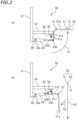
FIGS. 2 (a) and 2 (b) are views of an electric wire support device when seen in a direction along a rotation center line, whereFIG. 2 (a) illustrates a state where an electric wire support member is at an electric wire support position, andFIG. 2 (b) illustrates a state where the electric wire support member is at a retracted position. -
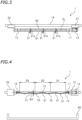
FIG. 3 is a plan view of a part of the electric wire twisting device. -
FIG. 4 is a side view of a part of the electric wire twisting device. -
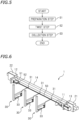
FIG. 5 is a flowchart of a method for producing a twisted electric wire. -
FIG. 6 is a perspective view of the electric wire twisting device in a twist step. -
FIG. 7 is a plan view of a part of the electric wire twisting device when holding by a first clamp and a second clamp is canceled. -
FIG. 8 is a perspective view of the electric wire twisting device when a twisted electric wire is collected. -
FIG. 9 is a view for describing sag of electric wires in a case where the electric wire support member is not provided. -
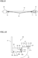
FIG. 10 is a view of an electric wire support device according to another preferred embodiment when seen in a direction along a rotation center line. -
FIGS. 11(a) and 11(b) are views of an electric wire support device according to another preferred embodiment when seen in a direction along a rotation center line, whereFIG. 11(a) illustrates a state where an electric wire support member is at an electric wire support position, andFIG. 11(b) illustrates a state where the electric wire support member is at a retracted position. -
FIG. 12 is a conceptual illustration for describing a method for supporting electric wires while sandwiching the electric wires from both sides. - A preferred embodiment of the present invention will be hereinafter described with reference to the drawings. As illustrated in
FIG. 1 , an electricwire twisting device 1 according to the present invention includes: afirst clamp 11 configured to hold one end of each of a firstelectric wire 51 and a secondelectric wire 52; and asecond clamp 12 configured to hold the other end of each of the firstelectric wire 51 and the secondelectric wire 52. The electricwire twisting device 1 also includes amotor 13 as a rotation actuator for rotating thefirst clamp 11. Themotor 13 is configured to rotate thefirst clamp 11 about a rotation center line CL. The rotation center line CL is an imaginary straight line extending from thefirst clamp 11 toward thesecond clamp 12, and in this preferred embodiment, is a straight line extending horizontally. - The
first clamp 11 and themotor 13 are supported by afirst holder 21, and thesecond clamp 12 is supported by asecond holder 22. The electricwire twisting device 1 includes arail 14 extending in parallel with the rotation center line CL. Thefirst holder 21 and thesecond holder 22 are supported by therail 14. At least one of thefirst holder 21 or thesecond holder 22 is slidably engaged with therail 14. Accordingly, at least one of thefirst clamp 11 and thesecond clamp 12 is movable in a direction along the rotation center line CL, and thus, a distance between thefirst clamp 11 and thesecond clamp 12 is adjustable. In this preferred embodiment, thefirst holder 21 is slidably engaged with therail 14, whereas thesecond holder 22 is non-slidably engaged with therail 14. Accordingly, thefirst clamp 11 is movable in the direction along the rotation center line CL, and thesecond clamp 12 does not move in the direction along the rotation center line CL. Alternatively, thesecond holder 22 may be slidably engaged with therail 14 with thefirst holder 21 being non-slidably engaged with therail 14. Both thefirst holder 21 and thesecond holder 22 may be slidably engaged with therail 14. - Although not shown, an actuator configured to move the
first holder 21 along therail 14 is disposed inside thefirst holder 21. The actuator is not limited to a specific type, and may be a motor, for example. - The electric
wire twisting device 1 includes electricwire support devices 30 configured to support the firstelectric wire 51 and the secondelectric wire 52. In this preferred embodiment, three electricwire support devices 30 are arranged in parallel with the rotation center line CL. Therail 14 and the electricwire support devices 30 are supported by an unillustrated frame. - As illustrated in
FIG. 2(a) , each of the electricwire support devices 30 includes: afirst strut 41 supported by the frame; asecond strut 42 extending laterally from thefirst strut 41; an electricwire support member 31; arotation shaft 32 configured to rotatably support the electricwire support member 31; and anair cylinder 33 configured to rotate the electricwire support member 31. Therotation shaft 32 is disposed at a side (at the left inFIG. 2(a) ) of the rotation center line CL. - The electric
wire support members 31 are disposed between thefirst clamp 11 and thesecond clamp 12 with respect to a direction along the rotation center line CL (seeFIG. 1 ) . As illustrated inFIGS. 2(a) and 2(b) , the electricwire support members 31 are configured to rotate between an electric wire support position below the rotation center line CL and a retracted position deviated from below the rotation center line CL. In this preferred embodiment, the position illustrated inFIG. 2(a) is the electric wire support position, and the position illustrated inFIG. 2(b) is the retracted position. The position below the rotation center line CL is a position lower than the rotation center line CL and on a vertical line A3 passing through the rotation center line CL. - In this preferred embodiment, the electric
wire support member 31 is constituted by an L-shaped support rod. The electricwire support member 31 includes: a straightsupport rod portion 31a extending in a direction intersecting with the rotation center line CL in plan view while the electricwire support member 31 is at the electric wire support position; abase rod portion 31b perpendicular to thesupport rod portion 31a; and acoupling portion 31c provided on thebase rod portion 31b. The term "direction intersecting with a member" includes both a direction perpendicularly intersecting with the member and a direction obliquely intersecting with the member. In this preferred embodiment, as illustrated inFIG. 3 , thesupport rod portion 31a perpendicularly intersects with the rotation center line CL in plan view. - As illustrated in
FIG. 2 (a) , the front end of thesecond strut 42 is provided with abracket 35 extending downward. Therotation shaft 32 rotatably couples thecoupling portion 31c of the electricwire support member 31 to thebracket 35. - The lower end of the
first strut 41 is provided with abracket 36, and abase portion 33a of theair cylinder 33 is rotatably coupled to thebracket 36. Afront end portion 33b of theair cylinder 33 is rotatably coupled to thecoupling portion 31c of the electricwire support member 31. As illustrated inFIG. 2 (a) , when arod 33R of theair cylinder 33 is stretched, the electricwire support member 31 moves to the electric wire support position as indicated by arrow A1. As illustrated inFIG. 2(b) , when therod 33R of theair cylinder 33 contracts, the electricwire support member 31 moves to the retracted position as indicated by arrow A2. - Positions of the electric
wire support members 31 of the electricwire support devices 30 are not specifically limited, but in this preferred embodiment, as illustrated inFIG. 4 , the electricwire support members 31 of the electricwire support devices 30 are individually disposed in a region B1 near thefirst clamp 11, an intermediate region B2, and a region B3 near thesecond clamp 12, and these regions are obtained by dividing equally an area between thefirst clamp 11 and thesecond clamp 12 into three regions. - As illustrated in
FIG. 4 , a collectingtray 45 for collecting a twistedelectric wire 50 is disposed below therail 14. The collectingtray 45 is disposed below the rotation center line CL and below the electric wire support position of the electricwire support members 31. - The configuration of the electric
wire twisting device 1 has been described above. Next, a method for producing the twistedelectric wire 50 by using the electricwire twisting device 1 will be described.FIG. 5 is a flowchart depicting a method for producing a twistedelectric wire 50. - First, a preparation step S1 is performed. In the preparation step S1, the
first clamp 11 holds an end of each ofelectric wires second clamp 12 holds the other end of each of theelectric wires air cylinder 33 is driven so that the electricwire support members 31 are moved to the electric wire support position. Consequently, theelectric wires electric wires first clamp 11 and thesecond clamp 12 and supported by the electric wire support members 31 (seeFIGS. 1 ,2(a) ,3, and 4 ). - In the electric
wire twisting device 1, the distance between thefirst clamp 11 and thesecond clamp 12 is adjustable in accordance with the lengths of the firstelectric wire 51 and the secondelectric wire 52. Tension on theelectric wires first clamp 11 and the second clamp 12 (hereinafter referred to as a clamp distance). For example, when the clamp distance is increased, theelectric wires electric wires electric wires electric wires electric wires electric wires electric wires 51 and 52 (seeFIG. 4 ) is 10 to 50 times as large as the diameter of each of theelectric wire 51 and 52 (where the diameters of theelectric wires electric wires electric wires electric wires - Then, a twist step S2 is performed. As illustrated in
FIG. 6 , in the twist step S2, themotor 13 is driven so that thefirst clamp 11 is thereby rotated about the rotation center line CL. Accordingly, the firstelectric wire 51 and the secondelectric wire 52 are twisted to be a twistedelectric wire 50. In twisting theelectric wires electric wires wire support members 31 are disposed below theelectric wires electric wires electric wires electric wire 50 can be reduced. As a result, high-quality twistedelectric wire 50 can be obtained. - When the
motor 13 is stopped, the twist step S2 is finished. After the end of the twist step S2, a collection step S3 of collecting the twistedelectric wire 50 is performed. In the collection step S3, theair cylinder 33 is driven so that the electricwire support members 31 are moved to the retracted position (seeFIG. 2(b) ). Accordingly, the electricwire support members 31 retract to a position deviated from a vertical line passing through the twistedelectric wire 50. Thereafter, as illustrated inFIG. 7 , thefirst clamp 11 and thesecond clamp 12 are opened so that holding by thefirst clamp 11 and thesecond clamp 12 is canceled. Then, as illustrated inFIG. 8 , the twistedelectric wire 50 is dropped by its self-weight to be collected in the collecting tray 45 (seeFIG. 4 ) . At this time, since the electricwire support members 31 are at the retracted position, the electricwire support members 31 do not hinder collection of the twistedelectric wire 50. - Although
FIGS. 7 and 8 illustrate a state where thefirst clamp 11 and thesecond clamp 12 stand vertically (a state where the pair of holding pieces are arranged laterally), thefirst clamp 11 and thesecond clamp 12 may cancel holding in a state where thefirst clamp 11 and thesecond clamp 12 stand laterally (a state where the pair of holding pieces is arranged vertically) . The state of theclamps - As described above, in the electric
wire twisting device 1 according to this embodiment, by moving the electricwire support members 31 to the electric wire support position, theelectric wires first clamp 11 and thesecond clamp 12 can be supported by the electricwire support members 31. Thus, the sag degree of theelectric wires electric wires clamps electric wires electric wires electric wires electric wires electric wires electric wires - In the electric
wire twisting device 1 according to this preferred embodiment, after theelectric wires wire support members 31 are moved from the electric wire support position to the retracted position so that the electricwire support members 31 thereby retract from below the twistedelectric wire 50. Thereafter, when holding by theclamps electric wire 50 is dropped downward without being hindered by the electricwire support members 31. Thus, the twistedelectric wire 50 can be easily collected only by canceling holding by theclamps electric wire 50 is measured after theelectric wires wire twisting device 1 according to this preferred embodiment, the pitch can be measured without being hindered by the electricwire support members 31, advantageously. - As described above, the electric
wire twisting device 1 according to this preferred embodiment is capable of suitably twisting theelectric wires electric wires electric wire 50 can be dropped downward and collected. - The electric
wire support members 31 only need to be movable between the electric wire support position and the retracted position, and a mode and a trajectory of the movement are not specifically limited. In this preferred embodiment, however, the electricwire support devices 30 include therotation shafts 32 rotatably supporting the electricwire support members 31, and the electricwire support members 31 are movable between the electric wire support position and the retracted position by rotation of the electricwire support members 31. As illustrated inFIGS. 2(a) and 2(b) , since the electricwire support members 31 are rotatable, the trajectory of movement of the electricwire support members 31 is relatively small. Thus, small space is sufficient for movement so that the electricwire support members 31 can be made compact. Therotation shafts 32 are disposed at the side of theelectric wires electric wires - As illustrated in
FIG. 9 , if the electricwire support members 31 were not provided, theelectric wires clamps wire twisting device 1 according to this preferred embodiment, as illustrated inFIG. 4 , the electricwire support member 31 is disposed in the intermediate region B2 among the regions obtained by dividing equally the area between thefirst clamp 11 and thesecond clamp 12 into three regions. Since center portions of theelectric wires electric wires electric wires electric wires clamps - Each of the electric
wire support devices 30 does not need to include the movement actuator for moving the electric wire support member 31 (theair cylinder 33 in the preferred embodiment), and movement of the electricwire support member 31 between the electric wire support position and the retracted position may be performed manually. In this preferred embodiment, however, since theair cylinder 33 is provided as a movement actuator for moving the electricwire support member 31, movement of the electricwire support member 31 from the electric wire support position to the retracted position and movement from the retracted position to the electric wire support position can be performed automatically. - In this preferred embodiment, the electric
wire support member 31 includes thesupport rod portion 31a extending in the direction intersecting with the rotation center line CL in plan view while the electricwire support member 31 is at the electric wire support position (seeFIG. 2(a) ). Thesupport rod portion 31a has a simple configuration. Thus, the advantages described above can be obtained at low cost with the simple configuration. - The electric
wire twisting device 1 according to this preferred embodiment includes the collectingtray 45 located below the electric wire support position of the electric wire support members 31 (seeFIG. 4 ) . After theelectric wires clamps electric wire 50 is dropped downward by its self-weight to be thereby easily collected in the collectingtray 45. - The method for collecting the twisted
electric wire 50 is not limited to a specific method. For example, a belt conveyor may be disposed below the rotation center line CL with the collecting tray being disposed at a downstream end of the belt conveyor in the conveyance direction. In this case, when holding by theclamps electric wire 50 is dropped onto the belt conveyor, conveyed by the belt conveyor, and then collected in the collecting tray. - In the electric
wire twisting device 1 according to this preferred embodiment, thefirst clamp 11 is movable in the direction along the rotation center line CL. Thus, the distance between thefirst clamp 11 and the second clamp 12 (clamp distance) is adjustable in accordance with the lengths of theelectric wires electric wires electric wires FIG. 3 , thefirst clamp 11 is moved toward thesecond clamp 12 to thereby adjust the clamp distance to 2/3. Thus, even in the case where electric wires to be twisted are changed to electric wires having a 2/3 length, these electric wires can be held by thefirst clamp 11 and thesecond clamp 12 while tension thereof is kept within a predetermined range. - In the case where the clamp distance is adjusted to 2/3 as described above, the electric
wire support member 31 near thefirst clamp 11 and thefirst clamp 11 are at the same location with respect to the direction along the rotation center line CL. Thus, while the electricwire support members 31 are at the retracted position, when thefirst clamp 11 is moved and then the electricwire support members 31 are moved from the retracted position to the electric wire support position, the electricwire support member 31 near thefirst clamp 11 collides against thefirst clamp 11. In such a case, while the electricwire support member 31 near thefirst clamp 11 is kept at the retracted position, the other electricwire support members 31 are moved to the electric wire support position. Accordingly, theelectric wires wire support members 31 while collision of the electricwire support member 31 near thefirst clamp 11 against thefirst clamp 11 is avoided. - In adjusting the clamp distance, while the electric
wire support members 31 are at the electric wire support position, thefirst clamp 11 may be moved in the direction along the rotation center line CL. In this case, the electricwire support member 31 near thefirst clamp 11 at the electric wire support position hinders movement of thefirst clamp 11. In such a case, however, it is sufficient to move the electricwire support member 31 near thefirst clamp 11 to the retracted position beforehand. Accordingly, collision against thefirst clamp 11 can be avoided, and hindering by the electricwire support member 31 in moving thefirst clamp 11 can be prevented. - In the electric
wire twisting device 1 according to this preferred embodiment, the plurality of electricwire support members 31 are provided along the direction parallel to the rotation center line CL. The number of electricwire support members 31 is not specifically limited, and three electricwire support members 31 are provided in this preferred embodiment. Thus, theelectric wires first clamp 11 and thesecond clamp 12 can be supported at three locations. As a result, the sag degree of theelectric wires electric wires - In the preparation step S1, the degree of tension applied by the
first clamp 11 and thesecond clamp 12 to theelectric wires electric wires electric wires electric wires electric wire 50 at the ends thereof can be reduced. In addition, since the tension is not excessively small, an increase in sag degree of theelectric wires electric wires electric wire 50 can be reduced, resulting in a high-quality twistedelectric wire 50. - Although one preferred embodiment of the present invention has been described above, the present invention is, of course, not limited to this preferred embodiment. The present invention can be performed in various modes. Next, another preferred embodiment will be briefly described.
- As illustrated in
FIG. 10 , in the preferred embodiment, thesupport rod portion 31a may include: asupport portion 31s located below the rotation center line CL while the electricwire support member 31 is at the electric wire support position; and shakestoppers 37 disposed at one and the other sides of thesupport portion 31s in a horizontal direction (i.e., the left-right direction inFIG. 10 ) orthogonal to the rotation center line CL and located above thesupport portion 31s. Theshake stoppers 37 may be made of upward projections, for example. As described above, as long as the electricwire support member 31 includes theshake stoppers 37, in twisting theelectric wires shake stoppers 37 prevent lateral shake of theelectric wires electric wires - As illustrated in
FIGS. 11(a) and 11(b) , thesupport rod portion 31a of the electricwire support member 31 may include arecess 31d that extends in a direction intersecting with the rotation center line CL in plan view while the electricwire support member 31 is at the electric wire support position and is recessed downward when seen in a direction along the rotation center line CL. In this preferred embodiment, a bottom portion of therecess 31d serves as a support portion and side portions of therecess 31d constitute the shake stoppers. Oneside portion 31f of therecess 31d extends to be gradually apart from the rotation center line CL in an upward direction. Theother side portion 31g extends vertically. Each of theside portions side portions FIGS. 11(a) and 11(b) , components already described in the preferred embodiment are denoted by the same reference characters. - In this preferred embodiment, since the
support rod portion 31a includes therecess 31d, lateral shake of theelectric wires electric wires - While the
first clamp 11 and thesecond clamp 12 hold theelectric wires electric wires FIG. 1 ). In this preferred embodiment, theside portion 31f of thesupport rod portion 31a is tilted with respect to the vertical line, and the lateral width of therecess 31d decreases in a downward direction. Thus, when the electricwire support member 31 is moved from the retracted position to the electric wire support position, therecess 31d enables theelectric wires electric wires - The electric
wire support members 31 described above are merely an example, and are not limited to a specific shape and specific dimensions. The cross-sectional shape of each electricwire support member 31 is not limited to a circle, and may be a rectangle or other shapes. - Although three electric
wire support members 31 are provided in the preferred embodiment, but the number of electricwire support members 31 may be one. In this case, the electricwire support member 31 is preferably disposed in the intermediate region B2 obtained by dividing equally the area between thefirst clamp 11 and thesecond clamp 12 into three regions. However, arrangement of the electricwire support member 31 is not specifically limited, and the electricwire support member 31 may be disposed in another region B1 or B3. - In the preferred embodiment, the electric
wire support devices 30 may be movable in a direction parallel to the rotation center line CL. For example, a rail extending in parallel with the rotation center line CL may be provided such that the electricwire support devices 30 are slidably engaged with the rail. The electricwire support devices 30 may be configured to be detachably disposed at a plurality of locations with respect to a direction parallel to the rotation center line CL. - In the case where the plurality of electric
wire support members 31 are provided, the distance between thefirst clamp 11 and the electricwire support member 31 near thefirst clamp 11 and the distance between thesecond clamp 12 and the electricwire support member 31 near thesecond clamp 12 with respect to the direction along the rotation center line CL may be equal or may be different from each other. The distance between two adjacent electricwire support members 31 may be equal to or different from the distance between thefirst clamp 11 and the electricwire support member 31 near thefirst clamp 11 or the distance between thesecond clamp 12 and the electricwire support member 31 near thesecond clamp 12. In a case where three or more electricwire support members 31 are provided, the distance between two adjacent electricwire support members 31 may be equal or different from each other. - The expression "to support electric wires" herein refers to prevention of downward movement of the electric wires. The expression "to support electric wires" is not limited to a case where the electric wires are supported from below and includes a case where the electric wires are sandwiched at both sides so that downward movement thereof is prevented. As illustrated in
FIG. 12 , for example, therecess 31d of the electricwire support member 31 may sandwich the firstelectric wire 51 and the secondelectric wire 52 at both sides to thereby prevent downward movement of the firstelectric wire 51 and the secondelectric wire 52. In this case, a space S may be generated between theelectric wires recess 31d. - Although the electric
wire support members 31 support the firstelectric wire 51 and the secondelectric wire 52 at the electric wire support position, while theelectric wires electric wires wire support members 31 in some cases. The term "support" herein is not limited to a case where theelectric wires wire support members 31 while being always in contact with the electricwire support members 31 and includes a case where theelectric wires wire support members 31 during twisting. - The number of electric wires twisted by the electric
wire twisting device 1 is not limited to two, and three or more electric wires may be twisted by the electricwire twisting device 1. - The
first clamp 11 and thesecond clamp 12 are not limited to any configuration. Thefirst clamp 11 may hold the firstelectric wire 51 and the secondelectric wire 52 by binding one end of the firstelectric wire 51 and one end of the secondelectric wire 52 together as in the preferred embodiment, or may include two holding portions that individually hold one end of the firstelectric wire 51 and one end of the secondelectric wire 52. Similarly, thesecond clamp 12 may hold the firstelectric wire 51 and the secondelectric wire 52 by binding the other end of the firstelectric wire 51 and the other end of the secondelectric wire 52 together, or may include two holding portions that individually hold the other end of the firstelectric wire 51 and the other end of the secondelectric wire 52. - In the preferred embodiment, in the twist step, the
first clamp 11 rotates about the rotation center line CL and thesecond clamp 12 does not rotate. Alternatively, thesecond clamp 12 may be configured to be rotatable about the rotation center line CL and the electricwire twisting device 1 may include a rotation actuator (e.g., a motor) that causes thesecond clamp 12 to rotate. Thefirst clamp 11 and thesecond clamp 12 may be configured to rotate in opposite directions in the twist step or may be configured such that only thesecond clamp 12 rotates in the twist step. - Although the electric
wire support members 31 are rotatable about the horizontal line in the preferred embodiment, the rotation direction thereof is not specifically limited. Specifically, the electricwire support members 31 may be rotatable about the vertical line and move while rotating in the horizontal direction. The mode of movement of the electricwire support members 31 is not specifically limited. The electricwire support members 31 may be configured to move in a direction intersecting with the rotation center line CL in plan view. The electricwire support members 31 may be configured to be movable between the electric wire support position and the retracted position by stretching and contracting in the direction intersecting with the rotation center line CL in plan view. The electricwire support members 31 may also be configured to move between the electric wire support position and the retracted position by parallel movement. - The movement actuator for moving the electric
wire support member 31 is not limited to theair cylinder 33. The movement actuator may be another type of actuator, such as a hydraulic cylinder, a solenoid, or a motor. - The rotation actuator for rotating the
first clamp 11 or thesecond clamp 12 is not limited to themotor 13. - The electric wire twisting device and the method for producing a twisted electric wire according to the present invention are effective especially for long wires (e.g., electric wires having a length of 4 to 5 m), but the length of electric wires are not specifically limited.
-
- 1
- electric wire twisting device
- 11
- first clamp
- 12
- second clamp
- 13
- motor (rotation actuator)
- 30
- electric wire support device
- 31
- electric wire support member
- 31a
- support rod portion
- 31d
- recess
- 31s
- support portion
- 32
- rotation shaft
- 33
- air cylinder (movement actuator)
- 37
- shake stoppers
- 45
- collecting tray
- 50
- twisted electric wire
- 51
- first electric wire
- 52
- second electric wire
- CL
- rotation center line
Claims (10)
- An electric wire twisting device (1) comprising:a first clamp (11) configured to hold one end of a first electric wire (51) and one end of a second electric wire (52);a second clamp (12) configured to hold another end of the first electric wire (51) and another end of the second electric wire (52);a rotation actuator configured to rotate at least one of the first clamp (11) and the second clamp (12) about a rotation center line (CL), the rotation center line (CL) extending from the first clamp (11) toward the second clamp (12); andan electric wire support member (31) configured to be movable between an electric wire support position and a retracted position, the electric wire support position being located between the first clamp (11) and the second clamp (12) and below the rotation center line (CL), the electric wire support member (31) being configured to support the first electric wire (51) and the second electric wire (52) while the electric wire support member (31) is at the electric wire support position, characterized in that the retracted position being deviated from below the rotation center line (CL), and the electric wire support member (31) being configured to allow the first electric wire (51) and the second electric wire (52) to drop downward without being hindered by the electric wire support member (31) while the electric wire support member (31) is at the retracted position.
- The electric wire twisting device (1) according to claim 1, further comprising a rotation shaft (32) configured to rotatably support the electric wire support member (31) between the electric wire support position and the retracted position.
- The electric wire twisting device (1) according to claim 1 or 2, wherein the electric wire support member (31) is disposed in an intermediate region (B2) among three regions (B1-B3), the three regions (B1-B3) being obtained by dividing equally an area between the first clamp (11) and the second clamp (12).
- The electric wire twisting device (1) according to any one of claims 1 to 3, further comprising a movement actuator (33) coupled to the electric wire support member (31), the movement actuator (33) being configured to move the electric wire support member (31) between the electric wire support position and the retracted position.
- The electric wire twisting device (1) according to any one of claims 1 to 4, wherein
the electric wire support member (31) includesa support portion (31s) located below the rotation center line (CL) while the electric wire support member (31) is at the electric wire support position, andshake stoppers (37) located at one side and another side of the support portion (31s) in a horizontal direction intersecting with the rotation center line (CL) while the electric wire support member (31) is at the electric wire support position and located above the support portion (31s). - The electric wire twisting device (1) according to any one of claims 1 to 5, whereinthe electric wire support member (31) includes a support rod portion (31a) extending along a direction intersecting with the rotation center line (CL) in plan view while the electric wire support member (31) is at the electric wire support position, andthe electric wire support member (31) has a recess (31d) that is recessed downward when seen in a direction along the rotation center line (CL).
- The electric wire twisting device (1) according to any one of claims 1 to 6, wherein at least one of the first clamp (11) and the second clamp (12) is movable in a direction along the rotation center line (CL).
- The electric wire twisting device (1) according to any one of claims 1 to 7, wherein the electric wire support member (31) comprises a plurality of electric wire support members (31) arranged along a direction parallel to the rotation center line (CL).
- A method for producing a twisted electric wire by the electric wire twisting device (1) according to claim 1, the method comprising:a preparation step of causing the first clamp (11) to hold one end and another end of the first electric wire (51), causing the second clamp (12) to hold one end and another end of the second electric wire (52), and moving the electric wire support member (31) to the electric wire support position;a twist step of rotating at least one of the first clamp (11) and the second clamp (12) to thereby twist the first electric wire (51) and the second electric wire (52); anda collection step of moving the electric wire support member (31) to the retracted position and canceling holding by the first clamp (11) and the second clamp (12) to thereby drop the first electric wire (51) and the second electric wire (52) that are twisted without being hindered by the electric wire support member (31) and collect the first electric wire (51) and the second electric wire (52) that are twisted.
- The method for producing a twisted electric wire according to claim 9, wherein in the preparation step, the first clamp (11) and the second clamp (12) apply tension to the first electric wire (51) and the second electric wires (52) such that a difference between a largest height and a smallest height of each of the first electric wire (51) and the second electric wire (52) is 10 to 50 times as large as a diameter of each of the first electric wire (51) and the second electric wire (52).
Applications Claiming Priority (2)
| Application Number | Priority Date | Filing Date | Title |
|---|---|---|---|
| JP2018058253A JP6916137B2 (en) | 2018-03-26 | 2018-03-26 | Electric wire twisting device and manufacturing method of twisted electric wire |
| PCT/JP2019/007287 WO2019187900A1 (en) | 2018-03-26 | 2019-02-26 | Electric wire twisting device and method for producing twisted electric wire |
Publications (3)
| Publication Number | Publication Date |
|---|---|
| EP3780020A1 EP3780020A1 (en) | 2021-02-17 |
| EP3780020A4 EP3780020A4 (en) | 2021-05-12 |
| EP3780020B1 true EP3780020B1 (en) | 2024-02-21 |
Family
ID=68061138
Family Applications (1)
| Application Number | Title | Priority Date | Filing Date |
|---|---|---|---|
| EP19774830.4A Active EP3780020B1 (en) | 2018-03-26 | 2019-02-26 | Electric wire twisting device and method for producing twisted electric wire |
Country Status (5)
| Country | Link |
|---|---|
| EP (1) | EP3780020B1 (en) |
| JP (1) | JP6916137B2 (en) |
| CN (1) | CN111886660B (en) |
| MA (1) | MA52237A (en) |
| WO (1) | WO2019187900A1 (en) |
Families Citing this family (1)
| Publication number | Priority date | Publication date | Assignee | Title |
|---|---|---|---|---|
| CN113997077B (en) * | 2021-12-30 | 2022-05-27 | 常州高尔登科技有限公司 | Metal cylinder material twisting and forming equipment for marine propeller |
Family Cites Families (12)
| Publication number | Priority date | Publication date | Assignee | Title |
|---|---|---|---|---|
| JPH07201628A (en) * | 1993-12-28 | 1995-08-04 | Fujikura Ltd | Untwisted wire method |
| JP4884024B2 (en) * | 2006-02-15 | 2012-02-22 | 矢崎総業株式会社 | Twisted wire manufacturing method and manufacturing apparatus |
| WO2008131346A2 (en) * | 2007-04-20 | 2008-10-30 | Concrete Technology Worldwide, Inc. | Method and system for manufacture of a wire cage |
| JP5221056B2 (en) * | 2007-04-26 | 2013-06-26 | 矢崎総業株式会社 | Wire twisting device |
| JP2011113656A (en) * | 2009-11-24 | 2011-06-09 | Sumitomo Wiring Syst Ltd | Manufacturing device of stranded electric wire, and manufacturing method of stranded electric wire |
| CN201594421U (en) * | 2009-12-04 | 2010-09-29 | 富港电子(东莞)有限公司 | Automatic wire cutting and twisting machine |
| US8176946B2 (en) * | 2010-08-18 | 2012-05-15 | Cheng Uei Precision Industry Co., Ltd. | Automatic wire cutting and twisting apparatus |
| PL2777053T3 (en) * | 2011-11-11 | 2016-06-30 | Schleuniger Holding Ag | Twisting device |
| CN104217823B (en) * | 2013-06-03 | 2016-08-24 | 日本自动机械株式会社 | Electric wire stranding device and method, twisting type cables manufacturing device and method |
| JP6689037B2 (en) | 2015-06-22 | 2020-04-28 | 新明和工業株式会社 | Wire twist device |
| WO2017159604A1 (en) * | 2016-03-14 | 2017-09-21 | 新明和工業株式会社 | Electric wire twisting device and electric wire twisting method |
| DE102016109151B3 (en) * | 2016-05-18 | 2017-09-14 | Lisa Dräxlmaier GmbH | twisting |
-
2018
- 2018-03-26 JP JP2018058253A patent/JP6916137B2/en active Active
-
2019
- 2019-02-26 EP EP19774830.4A patent/EP3780020B1/en active Active
- 2019-02-26 WO PCT/JP2019/007287 patent/WO2019187900A1/en not_active Ceased
- 2019-02-26 CN CN201980019448.9A patent/CN111886660B/en active Active
- 2019-02-26 MA MA052237A patent/MA52237A/en unknown
Also Published As
| Publication number | Publication date |
|---|---|
| WO2019187900A1 (en) | 2019-10-03 |
| EP3780020A1 (en) | 2021-02-17 |
| JP6916137B2 (en) | 2021-08-11 |
| MA52237A (en) | 2021-05-12 |
| JP2019169431A (en) | 2019-10-03 |
| EP3780020A4 (en) | 2021-05-12 |
| CN111886660A (en) | 2020-11-03 |
| CN111886660B (en) | 2021-11-05 |
Similar Documents
| Publication | Publication Date | Title |
|---|---|---|
| CN110891886B (en) | Operating device for sorting plant | |
| US8628131B2 (en) | Product gripper system | |
| EP3326794B1 (en) | Device for transporting and bending cut-outs | |
| CN101704389A (en) | Vehicle transfer apparatus | |
| CN101351394A (en) | Adjusting device for conveying channel on conveyor | |
| KR20190016584A (en) | Apparatus and method for handling metal products | |
| CN101924314A (en) | Electric wire keeps bar Handling device and electric wire group manufacture method | |
| EP3780020A1 (en) | Electric wire twisting device and method for producing twisted electric wire | |
| WO1989000964A2 (en) | Process and device for automatic transfer of garments to automatic folding machines and conveyor coathangers | |
| CN108892003A (en) | Automatic tube ejector and using the device rotor spinning machine and its change pipe method | |
| WO2018059730A1 (en) | Method and device for supplying laundry items to a laundry treatment device, in particular a mangle | |
| CN108840097B (en) | Material taking machine | |
| JP2001517742A (en) | Method and apparatus for separating strands | |
| US5094338A (en) | Conveyer device for bales, specifically on or in a bale or wire removal station | |
| KR20200137823A (en) | Adhesive apparatus of tape for box package | |
| US20080187412A1 (en) | Feeding Device and a Feeding Process For Components | |
| DE03710077T1 (en) | Wrapping | |
| JP7326424B2 (en) | A cable processing machine system and a method for removing one or more cables from a removal trough of a cable processing machine system | |
| FI88884C (en) | FRAME RELEASE FRAME RELEASE FRAME RING FOR SUSPENSION | |
| KR101539741B1 (en) | Former having vertical conveyor for preventing scratch of forged product | |
| JPH1099064A (en) | Apparatus for cutting stem root of bulbous vegetables | |
| JP6902401B2 (en) | Wire twist device | |
| CN119187395B (en) | A wire production line | |
| JP4216154B2 (en) | Electric wire processing machine | |
| FR2585515A1 (en) | Automated line for assembling antennas |
Legal Events
| Date | Code | Title | Description |
|---|---|---|---|
| STAA | Information on the status of an ep patent application or granted ep patent |
Free format text: STATUS: THE INTERNATIONAL PUBLICATION HAS BEEN MADE |
|
| PUAI | Public reference made under article 153(3) epc to a published international application that has entered the european phase |
Free format text: ORIGINAL CODE: 0009012 |
|
| STAA | Information on the status of an ep patent application or granted ep patent |
Free format text: STATUS: REQUEST FOR EXAMINATION WAS MADE |
|
| 17P | Request for examination filed |
Effective date: 20200907 |
|
| AK | Designated contracting states |
Kind code of ref document: A1 Designated state(s): AL AT BE BG CH CY CZ DE DK EE ES FI FR GB GR HR HU IE IS IT LI LT LU LV MC MK MT NL NO PL PT RO RS SE SI SK SM TR |
|
| AX | Request for extension of the european patent |
Extension state: BA ME |
|
| A4 | Supplementary search report drawn up and despatched |
Effective date: 20210413 |
|
| RIC1 | Information provided on ipc code assigned before grant |
Ipc: H01B 13/02 20060101AFI20210407BHEP Ipc: B21F 7/00 20060101ALI20210407BHEP |
|
| DAX | Request for extension of the european patent (deleted) | ||
| RAV | Requested validation state of the european patent: fee paid |
Extension state: KH Effective date: 20200907 Extension state: MA Effective date: 20200907 Extension state: TN Effective date: 20200907 |
|
| STAA | Information on the status of an ep patent application or granted ep patent |
Free format text: STATUS: EXAMINATION IS IN PROGRESS |
|
| 17Q | First examination report despatched |
Effective date: 20220722 |
|
| GRAP | Despatch of communication of intention to grant a patent |
Free format text: ORIGINAL CODE: EPIDOSNIGR1 |
|
| STAA | Information on the status of an ep patent application or granted ep patent |
Free format text: STATUS: GRANT OF PATENT IS INTENDED |
|
| INTG | Intention to grant announced |
Effective date: 20230915 |
|
| GRAS | Grant fee paid |
Free format text: ORIGINAL CODE: EPIDOSNIGR3 |
|
| GRAA | (expected) grant |
Free format text: ORIGINAL CODE: 0009210 |
|
| STAA | Information on the status of an ep patent application or granted ep patent |
Free format text: STATUS: THE PATENT HAS BEEN GRANTED |
|
| AK | Designated contracting states |
Kind code of ref document: B1 Designated state(s): AL AT BE BG CH CY CZ DE DK EE ES FI FR GB GR HR HU IE IS IT LI LT LU LV MC MK MT NL NO PL PT RO RS SE SI SK SM TR |
|
| P01 | Opt-out of the competence of the unified patent court (upc) registered |
Effective date: 20240113 |
|
| REG | Reference to a national code |
Ref country code: GB Ref legal event code: FG4D |
|
| REG | Reference to a national code |
Ref country code: CH Ref legal event code: EP |
|
| REG | Reference to a national code |
Ref country code: DE Ref legal event code: R096 Ref document number: 602019046949 Country of ref document: DE |
|
| REG | Reference to a national code |
Ref country code: IE Ref legal event code: FG4D |
|
| REG | Reference to a national code |
Ref country code: LT Ref legal event code: MG9D |
|
| REG | Reference to a national code |
Ref country code: NL Ref legal event code: MP Effective date: 20240221 |
|
| PG25 | Lapsed in a contracting state [announced via postgrant information from national office to epo] |
Ref country code: IS Free format text: LAPSE BECAUSE OF FAILURE TO SUBMIT A TRANSLATION OF THE DESCRIPTION OR TO PAY THE FEE WITHIN THE PRESCRIBED TIME-LIMIT Effective date: 20240621 |
|
| PG25 | Lapsed in a contracting state [announced via postgrant information from national office to epo] |
Ref country code: LT Free format text: LAPSE BECAUSE OF FAILURE TO SUBMIT A TRANSLATION OF THE DESCRIPTION OR TO PAY THE FEE WITHIN THE PRESCRIBED TIME-LIMIT Effective date: 20240221 |
|
| PG25 | Lapsed in a contracting state [announced via postgrant information from national office to epo] |
Ref country code: GR Free format text: LAPSE BECAUSE OF FAILURE TO SUBMIT A TRANSLATION OF THE DESCRIPTION OR TO PAY THE FEE WITHIN THE PRESCRIBED TIME-LIMIT Effective date: 20240522 |
|
| REG | Reference to a national code |
Ref country code: AT Ref legal event code: MK05 Ref document number: 1659840 Country of ref document: AT Kind code of ref document: T Effective date: 20240221 |
|
| PG25 | Lapsed in a contracting state [announced via postgrant information from national office to epo] |
Ref country code: HR Free format text: LAPSE BECAUSE OF FAILURE TO SUBMIT A TRANSLATION OF THE DESCRIPTION OR TO PAY THE FEE WITHIN THE PRESCRIBED TIME-LIMIT Effective date: 20240221 Ref country code: RS Free format text: LAPSE BECAUSE OF FAILURE TO SUBMIT A TRANSLATION OF THE DESCRIPTION OR TO PAY THE FEE WITHIN THE PRESCRIBED TIME-LIMIT Effective date: 20240521 Ref country code: NL Free format text: LAPSE BECAUSE OF FAILURE TO SUBMIT A TRANSLATION OF THE DESCRIPTION OR TO PAY THE FEE WITHIN THE PRESCRIBED TIME-LIMIT Effective date: 20240221 |
|
| PG25 | Lapsed in a contracting state [announced via postgrant information from national office to epo] |
Ref country code: ES Free format text: LAPSE BECAUSE OF FAILURE TO SUBMIT A TRANSLATION OF THE DESCRIPTION OR TO PAY THE FEE WITHIN THE PRESCRIBED TIME-LIMIT Effective date: 20240221 |
|
| PG25 | Lapsed in a contracting state [announced via postgrant information from national office to epo] |
Ref country code: AT Free format text: LAPSE BECAUSE OF FAILURE TO SUBMIT A TRANSLATION OF THE DESCRIPTION OR TO PAY THE FEE WITHIN THE PRESCRIBED TIME-LIMIT Effective date: 20240221 |
|
| PG25 | Lapsed in a contracting state [announced via postgrant information from national office to epo] |
Ref country code: RS Free format text: LAPSE BECAUSE OF FAILURE TO SUBMIT A TRANSLATION OF THE DESCRIPTION OR TO PAY THE FEE WITHIN THE PRESCRIBED TIME-LIMIT Effective date: 20240521 Ref country code: NO Free format text: LAPSE BECAUSE OF FAILURE TO SUBMIT A TRANSLATION OF THE DESCRIPTION OR TO PAY THE FEE WITHIN THE PRESCRIBED TIME-LIMIT Effective date: 20240521 Ref country code: NL Free format text: LAPSE BECAUSE OF FAILURE TO SUBMIT A TRANSLATION OF THE DESCRIPTION OR TO PAY THE FEE WITHIN THE PRESCRIBED TIME-LIMIT Effective date: 20240221 Ref country code: LT Free format text: LAPSE BECAUSE OF FAILURE TO SUBMIT A TRANSLATION OF THE DESCRIPTION OR TO PAY THE FEE WITHIN THE PRESCRIBED TIME-LIMIT Effective date: 20240221 Ref country code: IS Free format text: LAPSE BECAUSE OF FAILURE TO SUBMIT A TRANSLATION OF THE DESCRIPTION OR TO PAY THE FEE WITHIN THE PRESCRIBED TIME-LIMIT Effective date: 20240621 Ref country code: HR Free format text: LAPSE BECAUSE OF FAILURE TO SUBMIT A TRANSLATION OF THE DESCRIPTION OR TO PAY THE FEE WITHIN THE PRESCRIBED TIME-LIMIT Effective date: 20240221 Ref country code: GR Free format text: LAPSE BECAUSE OF FAILURE TO SUBMIT A TRANSLATION OF THE DESCRIPTION OR TO PAY THE FEE WITHIN THE PRESCRIBED TIME-LIMIT Effective date: 20240522 Ref country code: FI Free format text: LAPSE BECAUSE OF FAILURE TO SUBMIT A TRANSLATION OF THE DESCRIPTION OR TO PAY THE FEE WITHIN THE PRESCRIBED TIME-LIMIT Effective date: 20240221 Ref country code: ES Free format text: LAPSE BECAUSE OF FAILURE TO SUBMIT A TRANSLATION OF THE DESCRIPTION OR TO PAY THE FEE WITHIN THE PRESCRIBED TIME-LIMIT Effective date: 20240221 Ref country code: BG Free format text: LAPSE BECAUSE OF FAILURE TO SUBMIT A TRANSLATION OF THE DESCRIPTION OR TO PAY THE FEE WITHIN THE PRESCRIBED TIME-LIMIT Effective date: 20240221 Ref country code: AT Free format text: LAPSE BECAUSE OF FAILURE TO SUBMIT A TRANSLATION OF THE DESCRIPTION OR TO PAY THE FEE WITHIN THE PRESCRIBED TIME-LIMIT Effective date: 20240221 |
|
| PG25 | Lapsed in a contracting state [announced via postgrant information from national office to epo] |
Ref country code: PL Free format text: LAPSE BECAUSE OF FAILURE TO SUBMIT A TRANSLATION OF THE DESCRIPTION OR TO PAY THE FEE WITHIN THE PRESCRIBED TIME-LIMIT Effective date: 20240221 Ref country code: PT Free format text: LAPSE BECAUSE OF FAILURE TO SUBMIT A TRANSLATION OF THE DESCRIPTION OR TO PAY THE FEE WITHIN THE PRESCRIBED TIME-LIMIT Effective date: 20240621 |
|
| PG25 | Lapsed in a contracting state [announced via postgrant information from national office to epo] |
Ref country code: SE Free format text: LAPSE BECAUSE OF FAILURE TO SUBMIT A TRANSLATION OF THE DESCRIPTION OR TO PAY THE FEE WITHIN THE PRESCRIBED TIME-LIMIT Effective date: 20240221 Ref country code: PT Free format text: LAPSE BECAUSE OF FAILURE TO SUBMIT A TRANSLATION OF THE DESCRIPTION OR TO PAY THE FEE WITHIN THE PRESCRIBED TIME-LIMIT Effective date: 20240621 Ref country code: PL Free format text: LAPSE BECAUSE OF FAILURE TO SUBMIT A TRANSLATION OF THE DESCRIPTION OR TO PAY THE FEE WITHIN THE PRESCRIBED TIME-LIMIT Effective date: 20240221 Ref country code: LV Free format text: LAPSE BECAUSE OF FAILURE TO SUBMIT A TRANSLATION OF THE DESCRIPTION OR TO PAY THE FEE WITHIN THE PRESCRIBED TIME-LIMIT Effective date: 20240221 |
|
| PG25 | Lapsed in a contracting state [announced via postgrant information from national office to epo] |
Ref country code: DK Free format text: LAPSE BECAUSE OF FAILURE TO SUBMIT A TRANSLATION OF THE DESCRIPTION OR TO PAY THE FEE WITHIN THE PRESCRIBED TIME-LIMIT Effective date: 20240221 |
|
| PG25 | Lapsed in a contracting state [announced via postgrant information from national office to epo] |
Ref country code: SM Free format text: LAPSE BECAUSE OF FAILURE TO SUBMIT A TRANSLATION OF THE DESCRIPTION OR TO PAY THE FEE WITHIN THE PRESCRIBED TIME-LIMIT Effective date: 20240221 |
|
| PG25 | Lapsed in a contracting state [announced via postgrant information from national office to epo] |
Ref country code: LU Free format text: LAPSE BECAUSE OF NON-PAYMENT OF DUE FEES Effective date: 20240226 |
|
| PG25 | Lapsed in a contracting state [announced via postgrant information from national office to epo] |
Ref country code: EE Free format text: LAPSE BECAUSE OF FAILURE TO SUBMIT A TRANSLATION OF THE DESCRIPTION OR TO PAY THE FEE WITHIN THE PRESCRIBED TIME-LIMIT Effective date: 20240221 Ref country code: CZ Free format text: LAPSE BECAUSE OF FAILURE TO SUBMIT A TRANSLATION OF THE DESCRIPTION OR TO PAY THE FEE WITHIN THE PRESCRIBED TIME-LIMIT Effective date: 20240221 |
|
| PG25 | Lapsed in a contracting state [announced via postgrant information from national office to epo] |
Ref country code: SK Free format text: LAPSE BECAUSE OF FAILURE TO SUBMIT A TRANSLATION OF THE DESCRIPTION OR TO PAY THE FEE WITHIN THE PRESCRIBED TIME-LIMIT Effective date: 20240221 |
|
| PG25 | Lapsed in a contracting state [announced via postgrant information from national office to epo] |
Ref country code: SM Free format text: LAPSE BECAUSE OF FAILURE TO SUBMIT A TRANSLATION OF THE DESCRIPTION OR TO PAY THE FEE WITHIN THE PRESCRIBED TIME-LIMIT Effective date: 20240221 Ref country code: SK Free format text: LAPSE BECAUSE OF FAILURE TO SUBMIT A TRANSLATION OF THE DESCRIPTION OR TO PAY THE FEE WITHIN THE PRESCRIBED TIME-LIMIT Effective date: 20240221 Ref country code: RO Free format text: LAPSE BECAUSE OF FAILURE TO SUBMIT A TRANSLATION OF THE DESCRIPTION OR TO PAY THE FEE WITHIN THE PRESCRIBED TIME-LIMIT Effective date: 20240221 Ref country code: LU Free format text: LAPSE BECAUSE OF NON-PAYMENT OF DUE FEES Effective date: 20240226 Ref country code: EE Free format text: LAPSE BECAUSE OF FAILURE TO SUBMIT A TRANSLATION OF THE DESCRIPTION OR TO PAY THE FEE WITHIN THE PRESCRIBED TIME-LIMIT Effective date: 20240221 Ref country code: DK Free format text: LAPSE BECAUSE OF FAILURE TO SUBMIT A TRANSLATION OF THE DESCRIPTION OR TO PAY THE FEE WITHIN THE PRESCRIBED TIME-LIMIT Effective date: 20240221 Ref country code: CZ Free format text: LAPSE BECAUSE OF FAILURE TO SUBMIT A TRANSLATION OF THE DESCRIPTION OR TO PAY THE FEE WITHIN THE PRESCRIBED TIME-LIMIT Effective date: 20240221 |
|
| PG25 | Lapsed in a contracting state [announced via postgrant information from national office to epo] |
Ref country code: MC Free format text: LAPSE BECAUSE OF FAILURE TO SUBMIT A TRANSLATION OF THE DESCRIPTION OR TO PAY THE FEE WITHIN THE PRESCRIBED TIME-LIMIT Effective date: 20240221 |
|
| REG | Reference to a national code |
Ref country code: DE Ref legal event code: R097 Ref document number: 602019046949 Country of ref document: DE |
|
| PG25 | Lapsed in a contracting state [announced via postgrant information from national office to epo] |
Ref country code: MC Free format text: LAPSE BECAUSE OF FAILURE TO SUBMIT A TRANSLATION OF THE DESCRIPTION OR TO PAY THE FEE WITHIN THE PRESCRIBED TIME-LIMIT Effective date: 20240221 |
|
| PG25 | Lapsed in a contracting state [announced via postgrant information from national office to epo] |
Ref country code: IT Free format text: LAPSE BECAUSE OF FAILURE TO SUBMIT A TRANSLATION OF THE DESCRIPTION OR TO PAY THE FEE WITHIN THE PRESCRIBED TIME-LIMIT Effective date: 20240221 |
|
| REG | Reference to a national code |
Ref country code: BE Ref legal event code: MM Effective date: 20240229 |
|
| PLBE | No opposition filed within time limit |
Free format text: ORIGINAL CODE: 0009261 |
|
| STAA | Information on the status of an ep patent application or granted ep patent |
Free format text: STATUS: NO OPPOSITION FILED WITHIN TIME LIMIT |
|
| PG25 | Lapsed in a contracting state [announced via postgrant information from national office to epo] |
Ref country code: IT Free format text: LAPSE BECAUSE OF FAILURE TO SUBMIT A TRANSLATION OF THE DESCRIPTION OR TO PAY THE FEE WITHIN THE PRESCRIBED TIME-LIMIT Effective date: 20240221 |
|
| PG25 | Lapsed in a contracting state [announced via postgrant information from national office to epo] |
Ref country code: BE Free format text: LAPSE BECAUSE OF NON-PAYMENT OF DUE FEES Effective date: 20240229 |
|
| PG25 | Lapsed in a contracting state [announced via postgrant information from national office to epo] |
Ref country code: FR Free format text: LAPSE BECAUSE OF NON-PAYMENT OF DUE FEES Effective date: 20240421 |
|
| PG25 | Lapsed in a contracting state [announced via postgrant information from national office to epo] |
Ref country code: IE Free format text: LAPSE BECAUSE OF NON-PAYMENT OF DUE FEES Effective date: 20240226 |
|
| 26N | No opposition filed |
Effective date: 20241122 |
|
| GBPC | Gb: european patent ceased through non-payment of renewal fee |
Effective date: 20240521 |
|
| PG25 | Lapsed in a contracting state [announced via postgrant information from national office to epo] |
Ref country code: IE Free format text: LAPSE BECAUSE OF NON-PAYMENT OF DUE FEES Effective date: 20240226 Ref country code: FR Free format text: LAPSE BECAUSE OF NON-PAYMENT OF DUE FEES Effective date: 20240421 Ref country code: BE Free format text: LAPSE BECAUSE OF NON-PAYMENT OF DUE FEES Effective date: 20240229 |
|
| PGFP | Annual fee paid to national office [announced via postgrant information from national office to epo] |
Ref country code: DE Payment date: 20250218 Year of fee payment: 7 |
|
| PG25 | Lapsed in a contracting state [announced via postgrant information from national office to epo] |
Ref country code: SI Free format text: LAPSE BECAUSE OF FAILURE TO SUBMIT A TRANSLATION OF THE DESCRIPTION OR TO PAY THE FEE WITHIN THE PRESCRIBED TIME-LIMIT Effective date: 20240221 |
|
| PGFP | Annual fee paid to national office [announced via postgrant information from national office to epo] |
Ref country code: CH Payment date: 20250301 Year of fee payment: 7 |
|
| PG25 | Lapsed in a contracting state [announced via postgrant information from national office to epo] |
Ref country code: GB Free format text: LAPSE BECAUSE OF NON-PAYMENT OF DUE FEES Effective date: 20240521 |
|
| PG25 | Lapsed in a contracting state [announced via postgrant information from national office to epo] |
Ref country code: CY Free format text: LAPSE BECAUSE OF FAILURE TO SUBMIT A TRANSLATION OF THE DESCRIPTION OR TO PAY THE FEE WITHIN THE PRESCRIBED TIME-LIMIT; INVALID AB INITIO Effective date: 20190226 |
|
| PG25 | Lapsed in a contracting state [announced via postgrant information from national office to epo] |
Ref country code: HU Free format text: LAPSE BECAUSE OF FAILURE TO SUBMIT A TRANSLATION OF THE DESCRIPTION OR TO PAY THE FEE WITHIN THE PRESCRIBED TIME-LIMIT; INVALID AB INITIO Effective date: 20190226 |
|
| VS25 | Lapsed in a validation state [announced via postgrant information from nat. office to epo] |
Ref country code: MA Free format text: FAILURE TO ELECT DOMICILE IN THE NATIONAL COUNTRY Effective date: 20240522 |
|
| PG25 | Lapsed in a contracting state [announced via postgrant information from national office to epo] |
Ref country code: TR Free format text: LAPSE BECAUSE OF FAILURE TO SUBMIT A TRANSLATION OF THE DESCRIPTION OR TO PAY THE FEE WITHIN THE PRESCRIBED TIME-LIMIT Effective date: 20240221 |
|
| VS25 | Lapsed in a validation state [announced via postgrant information from nat. office to epo] |
Ref country code: MA Free format text: LAPSE BECAUSE OF FAILURE TO SUBMIT A TRANSLATION OF THE DESCRIPTION OR TO PAY THE FEE WITHIN THE PRESCRIBED TIME-LIMIT Effective date: 20240221 |