EP3779566A1 - Brille - Google Patents
Brille Download PDFInfo
- Publication number
- EP3779566A1 EP3779566A1 EP20188618.1A EP20188618A EP3779566A1 EP 3779566 A1 EP3779566 A1 EP 3779566A1 EP 20188618 A EP20188618 A EP 20188618A EP 3779566 A1 EP3779566 A1 EP 3779566A1
- Authority
- EP
- European Patent Office
- Prior art keywords
- positioning
- glasses
- positioning member
- bevel
- pressing member
- Prior art date
- Legal status (The legal status is an assumption and is not a legal conclusion. Google has not performed a legal analysis and makes no representation as to the accuracy of the status listed.)
- Granted
Links
Images


Classifications
-
- G—PHYSICS
- G02—OPTICS
- G02C—SPECTACLES; SUNGLASSES OR GOGGLES INSOFAR AS THEY HAVE THE SAME FEATURES AS SPECTACLES; CONTACT LENSES
- G02C5/00—Constructions of non-optical parts
- G02C5/12—Nose pads; Nose-engaging surfaces of bridges or rims
- G02C5/122—Nose pads; Nose-engaging surfaces of bridges or rims with adjustable means
- G02C5/124—Nose pads; Nose-engaging surfaces of bridges or rims with adjustable means for vertically varying the position of the lenses
-
- G—PHYSICS
- G02—OPTICS
- G02B—OPTICAL ELEMENTS, SYSTEMS OR APPARATUS
- G02B27/00—Optical systems or apparatus not provided for by any of the groups G02B1/00 - G02B26/00, G02B30/00
- G02B27/01—Head-up displays
- G02B27/017—Head mounted
- G02B27/0176—Head mounted characterised by mechanical features
-
- G—PHYSICS
- G02—OPTICS
- G02C—SPECTACLES; SUNGLASSES OR GOGGLES INSOFAR AS THEY HAVE THE SAME FEATURES AS SPECTACLES; CONTACT LENSES
- G02C5/00—Constructions of non-optical parts
- G02C5/12—Nose pads; Nose-engaging surfaces of bridges or rims
- G02C5/122—Nose pads; Nose-engaging surfaces of bridges or rims with adjustable means
-
- G—PHYSICS
- G02—OPTICS
- G02C—SPECTACLES; SUNGLASSES OR GOGGLES INSOFAR AS THEY HAVE THE SAME FEATURES AS SPECTACLES; CONTACT LENSES
- G02C13/00—Assembling; Repairing; Cleaning
- G02C13/001—Assembling; Repairing
-
- G—PHYSICS
- G02—OPTICS
- G02C—SPECTACLES; SUNGLASSES OR GOGGLES INSOFAR AS THEY HAVE THE SAME FEATURES AS SPECTACLES; CONTACT LENSES
- G02C5/00—Constructions of non-optical parts
- G02C5/12—Nose pads; Nose-engaging surfaces of bridges or rims
- G02C5/126—Nose pads; Nose-engaging surfaces of bridges or rims exchangeable or otherwise fitted to the shape of the nose
-
- G—PHYSICS
- G02—OPTICS
- G02B—OPTICAL ELEMENTS, SYSTEMS OR APPARATUS
- G02B27/00—Optical systems or apparatus not provided for by any of the groups G02B1/00 - G02B26/00, G02B30/00
- G02B27/01—Head-up displays
- G02B27/017—Head mounted
- G02B2027/0178—Eyeglass type
-
- G—PHYSICS
- G02—OPTICS
- G02C—SPECTACLES; SUNGLASSES OR GOGGLES INSOFAR AS THEY HAVE THE SAME FEATURES AS SPECTACLES; CONTACT LENSES
- G02C2200/00—Generic mechanical aspects applicable to one or more of the groups G02C1/00 - G02C5/00 and G02C9/00 - G02C13/00 and their subgroups
- G02C2200/06—Locking elements
-
- G—PHYSICS
- G02—OPTICS
- G02C—SPECTACLES; SUNGLASSES OR GOGGLES INSOFAR AS THEY HAVE THE SAME FEATURES AS SPECTACLES; CONTACT LENSES
- G02C2200/00—Generic mechanical aspects applicable to one or more of the groups G02C1/00 - G02C5/00 and G02C9/00 - G02C13/00 and their subgroups
- G02C2200/18—Adjustment ridges or notches
-
- G—PHYSICS
- G02—OPTICS
- G02C—SPECTACLES; SUNGLASSES OR GOGGLES INSOFAR AS THEY HAVE THE SAME FEATURES AS SPECTACLES; CONTACT LENSES
- G02C2200/00—Generic mechanical aspects applicable to one or more of the groups G02C1/00 - G02C5/00 and G02C9/00 - G02C13/00 and their subgroups
- G02C2200/32—Oblong hole
Definitions
- the application relates to glasses, and in particular, glasses having an adjustable nose pad mechanism.
- multiple types of glasses may need to be designed.
- consumers for household purpose or companies for commercial purpose may need to purchase multiple glasses of different sizes based on different actual users (for example, adults and children at home, or consumers of different generations and ages who come to visit).
- the price of a pair of virtual reality glasses or a pair of augmented reality glasses is relatively high, and therefore, consumers' desire to purchase may be reduced.
- an embodiment of the application provides glasses including a glasses frame, a nose pad, and an adjustment mechanism.
- the glasses frame includes a bridge, where the bridge has a groove provided in a vertical direction.
- the nose pad includes a positioning section and a support section, where the support section is connected to an end portion of the positioning section, the positioning section is slidably disposed in the groove, and the positioning section has a plurality of locking slots and a limiting slot.
- the adjustment mechanism is disposed at the glasses frame, and the adjustment mechanism includes a pressing member and a positioning member.
- the pressing member is disposed perpendicular to the groove, where one end of the pressing member protrudes from one side of the groove, and the other end penetrates through the groove and the limiting slot.
- the positioning member is disposed at the glasses frame and connected to the other end of the pressing member, where the positioning member is capable of moving from a positioning position to a release position by pushing of the pressing member. When the positioning member is located at the positioning position, the positioning member is inserted into one of the locking slots, and when the positioning member moves to the release position, the nose pad is capable of moving in the groove.
- the position of the nose pad can be adjusted up and down by using the adjustable mechanism disposed at the glasses frame.
- the adjustable mechanism disposed at the glasses frame In this way, only a single device is needed to meet users with different nose shapes and nose bridge heights. For commercial use, there is no need to purchase more glasses devices or replace nose pads of different sizes for various consumers with different nose shapes and nose bridge heights.
- an adjustment method is very simple, one only needs to press the pressing member and adjust the nose pad to a desired position, and then release the pressing member and drive the positioning member to return to an original position to be inserted into the nose pad to fix the nose pad to the desired position, thereby completing the adjustment of the nose pad.
- the adjustment mechanism may further include a first elastic element disposed between the glasses frame and the positioning member, to provide the positioning member with an elastic force.
- a first elastic element disposed between the glasses frame and the positioning member, to provide the positioning member with an elastic force.
- a bottom surface of an end portion of the positioning member has a first bevel
- a bottom surface of each of the locking slots has a second bevel.
- the first bevel corresponds to the second bevel.
- the user may first press the pressing member and adjust the nose pad to a longest state. Then after the user wears the glasses, by pressing the glasses down, the nose applies a force to the nose pad, so that the nose pad can be pushed up.
- the second bevel at the bottom of the locking slots will push the first bevel on the positioning member, so that the positioning member is pushed to the release position, and the nose pad is capable of moving up.
- the positioning member When the nose pad moves up until the positioning member corresponds to another pair of locking slots, the positioning member returns to the positioning position under the elastic force of the first elastic element, so that the positioning member is inserted into the locking slots. If the nose pad is still not adjusted to the correct position at this time, one can continue to push the nose pad and repeat the above action until the nose pad is in the desired position.
- the adjustment mechanism may further include a second elastic element disposed in the groove and disposed between the glasses frame and the positioning section of the nose pad, to provide the positioning section with an elastic force.
- the second elastic element is disposed between the glasses frame and the positioning section of the nose pad, so that a force of pushing out may be provided to the nose pad. In this way, after the pressing member is pressed, the nose pad does not need to be manually pulled out, and the nose pad will be pushed out of the groove under the elastic force of the second elastic element, which can save a procedure for the user to operate the adjustment.
- the positioning member includes a pushing part and an insertion part.
- the pushing part abuts the pressing member.
- the insertion part is connected to the pushing part, and the insertion part is perpendicular to the pushing part.
- the positioning member is located at the positioning position, the insertion part is inserted into one of the locking slots. Therefore, by providing the pushing part, the pressing member can be reliably pressed on the positioning member.
- the insertion part may be disposed according to the shape and position of the locking slot, so that the positioning member can be more easily and accurately inserted into the locking slot.
- the pressing member may include a convex part, the pushing part includes a through hole, and the convex part correspondingly penetrates through the through hole. In this way, the pressing member is reliably connected to the positioning member, and the pressing member can reliably push the positioning member, or drive the positioning member to return to the positioning position.
- the insertion part extends from left and right sides of the pushing part, and the locking slots are provided on left and right sides of the limiting slot.
- the insertion part is correspondingly inserted into two locking slots located at the same height on the left and right sides of the limiting slot.
- a bottom surface of an end portion of the insertion part has a first bevel
- a bottom surface of each of the locking slots has a second bevel.
- the first bevel corresponds to the second bevel.
- the positioning member may include a plug-in part and a stopper.
- the plug-in part abuts the pressing member, and the stopper is connected to the plug-in part and extends from two sides of the insertion part.
- the plug-in part is inserted into one of the locking slots, and the stopper abuts against the positioning section.
- the pressing member may also directly abut against the plug-in part. Since omitting the pushing part means that there is no mechanism that can abut against the positioning section to stop the positioning member at the positioning position, by providing the stopper, the function of abutting against the positioning section to stop may also be provided to the positioning member.
- a bottom surface of an end portion of the plug-in part has a third bevel
- a bottom surface of each of the locking slots has a fourth bevel.
- the third bevel corresponds to the fourth bevel.
- the pressing member and the positioning member are an integral structure
- the positioning section further comprises an assembly port provided above the limiting slot, and the pressing member penetrates through the assembly port to the limiting slot. Because the pressing member and the positioning member are an integral structure, only one element needs to be made in production, and assembly of the adjustment structure can be completed by assembling a single element during assembly, which can reduce procedures during assembling, a number of elements, and production time.
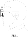
- FIG. 1 is a schematic diagram of wearing glasses according to an embodiment of the application
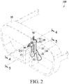
- FIG. 2 is a partial three-dimensional perspective view of the glasses according to an embodiment of the application
- FIG. 3 is a partial exploded view of the glasses according to an embodiment of the application
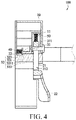
- FIG. 4 is a cross-sectional view of the glasses taken along line 4-4 in FIG. 2 according to an embodiment of the application
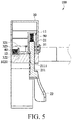
- FIG. 5 is a cross-sectional view of the glasses taken along line 5-5 in FIG. 2 according to an embodiment of the application
- FIG. 6 is a cross-sectional view of pressing a pressing member to move a positioning member to a release position of the glasses according to an embodiment of the application.
- glasses 100 of this embodiment may be generally worn glasses 100, and may also be virtual reality glasses, augmented reality glasses, or the like. Glasses for different users to wear need to be provided.
- the glasses 100 of this embodiment include a glasses frame 10, a nose pad 20, and an adjustment mechanism 30.
- the glasses frame 10 includes a bridge 13, where the bridge 13 has a groove 11 provided in a vertical direction.
- the bridge 13 refers to a connecting member of the glasses frame 10 located between similar lens structures on two sides.
- the vertical direction herein refers to an up-down direction that is perpendicular to a horizontal plane direction relative to the ground when the glasses 100 are in a wearing state shown in FIG. 1 .
- the nose pad 20 includes a positioning section 21 and a support section 22, where the support section 22 is connected to an end portion of the positioning section 21.
- the support section 22 is a mechanism in contact with the nose.
- the support section 22 is in a common nose pad shape and has two symmetrical nose pads on the left and right sides.
- the positioning section 21 is slidably disposed in the groove 11.
- the positioning section 21 has a plurality of locking slots 211 and a limiting slot 212.
- the plurality of locking slots 211 is arranged in pairs of two on the left and right sides, and a plurality of pairs is arranged from top to bottom.
- the limiting slot 212 is provided between the locking slots 211 on the left and the locking slots 211 on the right.
- the limiting slot is a vertical channel from top to bottom, which is used to allow the nose pad 20 to slide up and down without being stopped by a pressing member 31 of the adjustment mechanism 30. Details are provided below.
- the adjustment mechanism 30 is disposed at the glasses frame 10, and the adjustment mechanism 30 includes a pressing member 31 and a positioning member 32.
- the pressing member 31 is disposed perpendicular to the groove 11, where one end of the pressing member 31 protrudes from one side of the groove 11, and the other end penetrates through the groove 11 and the limiting slot 212.
- the pressing member 31 of this embodiment is an element having an oblate shape at one end and a long cylindrical shape at the other end.
- the pressing member 31 penetrates in a direction perpendicular to the groove 11 (that is, a direction parallel to the horizontal plane), and correspondingly penetrates into the position of the limiting slot 212. Because of the limiting slot 212, when the nose pad 20 moves up and down, the pressing member 31 is located at the position of the limiting slot 212, so that the nose pad 20 will not be unable to move up and down because of the pressing member 31 that penetrates through.
- a length of the limiting slot 212 may also limit a range in which the nose pad 20 is capable of moving up and down.
- the nose pad 20 moves down until an upper boundary of the limiting slot 212 abuts against the pressing member 31, the nose pad 20 cannot continue to move down.
- the nose pad 20 is pushed up and the nose pad 20 moves up until a lower boundary of the limiting slot 212 abuts against the pressing member 31, the nose pad 20 cannot continue to move up. In this way, problems such as the nose pad 20 being excessively pulled out and damaged can also be avoided.
- the pressing member 31 has an oblate end that protrudes from the inside of the glasses frame 10, so that a user can press and operate the pressing member 31, while an outward appearance of the glasses frame 10 can be maintained.
- the positioning member 32 is disposed at the glasses frame 10 and connected to the other end of the pressing member 31, where the positioning member 32 is capable of moving from a positioning position to a release position by pushing of the pressing member 31; when the positioning member 32 is located at the positioning position, the positioning member 32 is inserted into one of the locking slots 211, and when the positioning member 32 moves to the release position, the nose pad 20 is capable of moving in the groove 11 along the limiting slot 212 without limiting of the adjustment mechanism 30.
- the positioning member 32 is located at the positioning position.
- the pressing member 31 is only connected to the positioning member 32 and does not push the positioning member 32, and the positioning member 32 is inserted into one pair of locking slots 211 of the plurality of locking slots 211.
- the locking slots 211 may be provided only on a single side, and the positioning member 32 is inserted into one of the locking slots 211.
- FIG. 6 is a schematic action diagram of the pressing member 31 being pressed.
- the positioning member 32 is capable of moving from the positioning position to the release position by pushing of the pressing member 31.
- the nose pad 20 is capable of moving in the groove 11 along the limiting slot 212 relative to the pressing member 31 without limiting of the adjustment mechanism 30 until the positioning member 32 corresponds to a position of one of the locking slots 211.
- the positioning member 32 moves to the positioning position, so that the nose pad 20 can be positioned at the desired position.
- a first elastic element 40 is not provided, the displacement of the positioning member 32 can still be driven by operating the pressing member 31.
- the position of the nose pad 20 can be adjusted up and down by providing the adjustable mechanism disposed at the nose pad 20. In this way, only a single device is needed to meet users with different nose shapes and nose bridge heights. For commercial use, there is no need to purchase more glasses 100 or replace nose pads 20 of different sizes for various consumers with different nose shapes and nose bridge heights.
- an adjustment method of the glasses 100 of this embodiment is very simple, one only needs to press the pressing member 31 and adjust the nose pad 20 to a desired position, and then release the pressing member 31 and drive the positioning member 32 to return to an original position to be inserted into the locking slots 211 of the nose pad 20 to fix the nose pad 20 to the desired position, thereby completing the adjustment of the nose pad 20.
- the adjustment mechanism 30 further includes a first elastic element 40 disposed between the glasses frame 10 and the positioning member 32, to provide the positioning member 32 with an elastic force.
- a first elastic element 40 disposed between the glasses frame 10 and the positioning member 32, to provide the positioning member 32 with an elastic force.
- one end of the first elastic element 40 abuts against the glasses frame 10, and the other end abuts against a rear side of the positioning member 32.
- the positioning member 32 presses the first elastic element 40, so that the first elastic element 40 generates an elastic force due to compression.
- the pushing force of the pressing member 31 disappears, the positioning member 32 is pushed to the positioning position under the elastic force of the first elastic element 40.
- the user only need to release the pressing member 31 to make the positioning member 32 return to the positioning position under the action of the first elastic element 40.
- a bottom surface of an end portion of the positioning member 32 has a first bevel 3222, and a bottom surface of each of the locking slots 211 has a second bevel 2111.
- the first bevel 3222 corresponds to the second bevel 2111.
- the user may first press the pressing member 31 and adjust the nose pad 20 to a longest state. Subsequently, the user directly wears the glasses 100 in this state, and then by pressing the glasses 100 down, the nose applies a force to the nose pad 20, so that the nose pad 20 can be pushed up.
- the second bevel 2111 at the bottom of the locking slot 211 will push the first bevel 3222 on the positioning member 32, so that the positioning member 32 is pushed to the release position, and the nose pad 20 is capable of moving up.
- the positioning member 32 moves up until the positioning member 32 corresponds to another pair of locking slots 211, the positioning member 32 returns to the positioning position under the elastic force of the first elastic element 40, so that the positioning member 32 is inserted into the locking slots 211. If the nose pad 20 is still not adjusted to the correct position at this time, one can continue to push the nose pad 20 and repeat the above action until the nose pad 20 is in the desired position.
- the adjustment mechanism 30 further includes a second elastic element 50 disposed in the groove 11 and disposed between the glasses frame 10 and the positioning section 21 of the nose pad 20, to provide the positioning section 21 with an elastic force.
- the second elastic element 50 is disposed between the glasses frame 10 and the positioning section 21 of the nose pad 20, so that a force of pushing out may be provided to the nose pad 20. In this way, after the pressing member 31 is pressed, the nose pad 20 does not need to be manually pulled out, and the nose pad 20 will be pushed out of the groove 11 under the elastic force of the second elastic element 50, which can save a procedure for the user to operate the adjustment.
- the positioning member 32 includes a pushing part 321 and an insertion part 322.
- the pushing part 321 abuts the pressing member 31, and to make the pushing part 321 abut the pressing member 31 more reliably, the pressing member 31 in this embodiment includes a convex part 311, the pushing part 321 includes a through hole 3211, and the convex part 311 correspondingly penetrates through the through hole 3211.
- the convex part 311 and the through hole 3211 may also be omitted as long as the pushing part 321 and the pressing member 31 abut each other.
- the pushing part 321 extends upright.
- the insertion part 322 is connected to the pushing part 321 and the insertion part 322 is perpendicular to the pushing part 321.
- the insertion part 322 is inserted into one pair of the locking slots 211.
- the insertion part 322 extends from the left and right sides of the pushing part 321 to an arm-like mechanism.
- the plurality of locking slots 211 is two-to-two correspondingly provided on the left and right sides of the limiting slot 212.
- the insertion part 322 is correspondingly inserted into the locking slots 211 located at the same height on the left and right sides of the limiting slot 212.
- shapes of the locking slots 211 and the insertion part 322 may correspond to each other, so that the positioning member 32 is more easily and accurately inserted into the locking slots 211.
- the positioning member 32 may include a plate 323 connected to the rear of the insertion part 322.
- the shape or size of the plate 323 may be set according to the shape of the first elastic element 40.
- the plate 323 may be circular and slightly larger than the diameter of the first elastic element 40, so that the plate 323 can reliably abut against the first elastic element 40.
- a concave part 12 may be provided on the glasses frame 10 at a position adjacent to the plate 323.
- the plate 323 When the plate 323 is pushed to the right side of the figure under the elastic force of the first elastic element 40, the plate 323 can be stopped at the positioning position by the concave part 12, and the concave part 12 may also provide certain cushioning and stopping functions.
- FIG. 7 is a partial three-dimensional perspective view of glasses according to another embodiment of the application
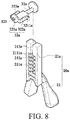
- FIG. 8 is a partial exploded view of the glasses according to another embodiment of the application
- FIG. 9 is a partial exploded view of the glasses from another angle of view according to another embodiment of the application
- FIG. 10 is a cross-sectional view of the glasses taken along line 10-10 in FIG. 7 according to another embodiment of the application
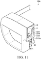
- FIG. 11 is a cross-sectional view of the glasses according to another embodiment of the application.
- the same elements and connection relationships as those in the previous embodiment will be represented by the same element symbols and will not be described repeatedly.
- Main differences between this embodiment and the previous embodiment are the structure of a nose pad 20a and the structure of a positioning member 32a, which will be described in detail below.
- each of the plurality of locking slots 211a of the positioning section 21a of the nose pad 20a of the glasses 100a has a fourth bevel 2111a at the bottom.
- the two locking slots 211a at the same height on the left and right sides are formed into a structure that is connected to each other with the limiting slot 212a, which is different from the previous embodiment in which the locking slots 211 are respectively provided on the left and right sides of the limiting slot 212 and are not connected.
- the positioning section 21a further includes an assembly port 213a provided above the corresponding limiting slot 212a, so that the pressing member 31a can penetrate through the assembly port 213a to the limiting slot 212a.
- the positioning member 32a of this embodiment includes a plug-in part 321a and a stopper.
- the stopper is exemplified by two stopping parts 322a disposed at the left and right, so that a force is relatively even. In some implementations, only a single stopping part may be disposed to provide a stopping effect.
- the plug-in part 321a abuts the pressing member 31a and has a third bevel 3211a on the bottom surface of the front end of the plug-in part 321a.
- the pressing member 31a and the positioning member 32a are an integral structure, and therefore, the pressing member 31a is directly connected to the front of the plug-in part 321a.
- the pressing member 31a and the positioning member 32a may still maintain a two-piece structure, as long as the pressing member 31a abuts the plug-in part 321a.
- the two stopping parts 322a of this embodiment are connected to the plug-in part 321a and respectively extend parallel to the two sides of the plug-in part 321a.
- the plug-in part 321a is inserted into one of the locking slots 211a, and the two stopping parts 322a respectively abut against the glasses frame 10 adjacent to the locking slots 211a.
- the two stopping parts 322a stop the positioning member 32a at the positioning position under stopping of the glasses frame 10.
- FIG. 11 when the positioning member 32a is located at the positioning position, the two stopping parts 322a respectively abut against one side wall of the groove 11 of the glasses frame 10, to stop the positioning member 32a from moving towards the groove 11 continuously.
- a bottom surface of an end portion of the plug-in part 321a has a third bevel 3211a
- a bottom surface of each of the locking slots 211a has a fourth bevel 2111a.
- the third bevel 3211a corresponds to the fourth bevel 2111a.
- the nose applies a force to the nose pad 20, so that the nose pad 20 can be pushed up.
- the fourth bevel 2111a at the bottom of the locking slot 211a will push the third bevel 3211a on the positioning member 32a, so that the positioning member 32a is pushed to the release position, and the nose pad 20 is capable of moving up.
- the adjustable nose pad 20 or 20a can be provided to enable the nose pad 20 or 20a to adjust its position up and down. In this way, multiple users with different nose shapes and nose bridge heights can be matched.
- an adjustment method is very simple. One only needs to press the pressing member 31 or 31a and adjust the nose pad 20 or 20a to a desired position, and then release the pressing member 31 or 31a and drive the positioning member 32 or 32a to return to an original position to be inserted into the nose pad 20 or 20a to fix the nose pad 20 or 20a to the desired position, thereby completing the position adjustment of the nose pad 20 or 20a. Only a pair of glasses 100 or 100a is needed to meet the needs of multiple users of most nose shapes and nose bridge heights.
Landscapes
- Physics & Mathematics (AREA)
- General Physics & Mathematics (AREA)
- Optics & Photonics (AREA)
- Health & Medical Sciences (AREA)
- Ophthalmology & Optometry (AREA)
- Eyeglasses (AREA)
- Lasers (AREA)
Applications Claiming Priority (1)
| Application Number | Priority Date | Filing Date | Title |
|---|---|---|---|
| TW108128812A TWI692657B (zh) | 2019-08-13 | 2019-08-13 | 眼鏡 |
Publications (3)
| Publication Number | Publication Date |
|---|---|
| EP3779566A1 true EP3779566A1 (de) | 2021-02-17 |
| EP3779566B1 EP3779566B1 (de) | 2024-01-17 |
| EP3779566C0 EP3779566C0 (de) | 2024-01-17 |
Family
ID=71894681
Family Applications (1)
| Application Number | Title | Priority Date | Filing Date |
|---|---|---|---|
| EP20188618.1A Active EP3779566B1 (de) | 2019-08-13 | 2020-07-30 | Brille |
Country Status (6)
| Country | Link |
|---|---|
| US (1) | US11662604B2 (de) |
| EP (1) | EP3779566B1 (de) |
| JP (1) | JP7013530B2 (de) |
| KR (1) | KR102450077B1 (de) |
| CN (1) | CN112394513A (de) |
| TW (1) | TWI692657B (de) |
Cited By (1)
| Publication number | Priority date | Publication date | Assignee | Title |
|---|---|---|---|---|
| RU2766396C1 (ru) * | 2021-04-30 | 2022-03-15 | Александр Григорьевич ВИЛЛЕР | Система и способ для чрескожной сосудистой пункции |
Families Citing this family (12)
| Publication number | Priority date | Publication date | Assignee | Title |
|---|---|---|---|---|
| CN113093391A (zh) * | 2021-04-23 | 2021-07-09 | 维沃移动通信有限公司 | 可穿戴设备 |
| CN113819942A (zh) * | 2021-08-24 | 2021-12-21 | 歌尔光学科技有限公司 | 眼镜用人机工学数据测量工具 |
| CN119768727A (zh) * | 2022-03-24 | 2025-04-04 | 苹果公司 | 可调节头戴式设备 |
| US20230393416A1 (en) * | 2022-06-06 | 2023-12-07 | Prohero Group Co., Ltd | Eyeglasses |
| US12436408B2 (en) | 2022-11-11 | 2025-10-07 | Htc Corporation | Wearable device |
| TWI836719B (zh) * | 2022-11-11 | 2024-03-21 | 宏達國際電子股份有限公司 | 穿戴裝置 |
| KR102752022B1 (ko) | 2022-12-12 | 2025-01-07 | 광주대학교산학협력단 | 높이 및 방향조절이 가능한 코받침대를 구비한 안경 |
| WO2024142942A1 (ja) * | 2022-12-28 | 2024-07-04 | パナソニックIpマネジメント株式会社 | 装着装置 |
| CN116719178A (zh) * | 2023-06-08 | 2023-09-08 | 歌尔科技有限公司 | 鼻托模组和vr眼镜 |
| KR102914988B1 (ko) * | 2023-10-17 | 2026-01-19 | 이동용 | 블라인드 일체형 사격용 안경 |
| WO2025154841A1 (ko) * | 2024-01-17 | 2025-07-24 | 엘지전자 주식회사 | 전자 디바이스 |
| KR102817711B1 (ko) | 2024-09-03 | 2025-06-11 | 주식회사 아이로나 | 스포츠 안경 |
Citations (6)
| Publication number | Priority date | Publication date | Assignee | Title |
|---|---|---|---|---|
| US5971538A (en) * | 1998-10-30 | 1999-10-26 | Hewlett-Packard Company | Articulated nose bridge for head mounted display |
| US20020067461A1 (en) * | 2000-12-06 | 2002-06-06 | Bell John Louis | Neck-saver eyeglass frames for bi-focals |
| US20140375948A1 (en) * | 2013-06-25 | 2014-12-25 | Injextech Inc. | Pair of glasses with an adjustable nose pad for fine-tuning adjustment |
| US8931894B1 (en) * | 2013-07-10 | 2015-01-13 | Lin Yun Chen | Glasses and nose pad assembly thereof |
| WO2015164276A1 (en) * | 2014-04-25 | 2015-10-29 | Osterhout Group, Inc. | Head-worn computing systems |
| US20180059434A1 (en) * | 2016-08-29 | 2018-03-01 | Osterhout Group, Inc. | Adjustable nose bridge assembly for headworn computer |
Family Cites Families (17)
| Publication number | Priority date | Publication date | Assignee | Title |
|---|---|---|---|---|
| FR2653238B2 (fr) * | 1988-12-15 | 1992-01-17 | Essilor Int | Monture de lunettes. |
| US7048371B1 (en) * | 2004-05-27 | 2006-05-23 | Moore Gregory S | Sports training glasses |
| US7497570B2 (en) * | 2006-05-11 | 2009-03-03 | Bushnell, Inc. | Adjustable nose pad system |
| US9158116B1 (en) * | 2014-04-25 | 2015-10-13 | Osterhout Group, Inc. | Temple and ear horn assembly for headworn computer |
| US7631967B1 (en) * | 2008-07-23 | 2009-12-15 | High Rainbow Ent. Co., Ltd. | Eyeglass nose-pad, eyeglass assembly and fabricating method of the same |
| TWI560485B (en) * | 2011-05-05 | 2016-12-01 | Ziba Labs Llc | Adjustable eyewear |
| CN202583611U (zh) * | 2011-10-15 | 2012-12-05 | 付祖家 | 鼻托高度可调式镜架 |
| CN203275807U (zh) | 2013-05-15 | 2013-11-06 | 陈建男 | 一种自由搭配副镜框新型眼镜 |
| CN203981994U (zh) | 2014-08-21 | 2014-12-03 | 陈建男 | 眼镜鼻垫调整结构 |
| KR102196106B1 (ko) | 2016-10-03 | 2020-12-30 | 노리오 세키 | 원근 양용 안경형의 프레임 |
| TWM544017U (zh) * | 2017-03-02 | 2017-06-21 | Prohero Group Co Ltd | 眼鏡鼻托調整結構 |
| TWI639039B (zh) | 2017-09-08 | 2018-10-21 | 雅德視國際股份有限公司 | 眼鏡之鼻托調整結構 |
| US11095873B2 (en) | 2017-09-22 | 2021-08-17 | Sony Interactive Entertainment Inc. | Head-mounted display |
| US20190196227A1 (en) * | 2017-12-22 | 2019-06-27 | North Inc. | Wearable heads-up displays employing a core wire communicatively coupled to a radio as an antenna |
| CN108761791A (zh) | 2018-05-31 | 2018-11-06 | 深圳市零度智控科技有限公司 | Ar眼镜 |
| CN208224625U (zh) | 2018-06-21 | 2018-12-11 | 宜视智能科技(苏州)有限公司 | Ar智能眼镜 |
| KR101933627B1 (ko) | 2018-10-31 | 2018-12-28 | 박영보 | 스포츠용 고글 |
-
2019
- 2019-08-13 TW TW108128812A patent/TWI692657B/zh active
-
2020
- 2020-05-28 CN CN202010465401.XA patent/CN112394513A/zh active Pending
- 2020-07-06 JP JP2020116341A patent/JP7013530B2/ja active Active
- 2020-07-10 US US16/925,458 patent/US11662604B2/en active Active
- 2020-07-17 KR KR1020200089085A patent/KR102450077B1/ko active Active
- 2020-07-30 EP EP20188618.1A patent/EP3779566B1/de active Active
Patent Citations (6)
| Publication number | Priority date | Publication date | Assignee | Title |
|---|---|---|---|---|
| US5971538A (en) * | 1998-10-30 | 1999-10-26 | Hewlett-Packard Company | Articulated nose bridge for head mounted display |
| US20020067461A1 (en) * | 2000-12-06 | 2002-06-06 | Bell John Louis | Neck-saver eyeglass frames for bi-focals |
| US20140375948A1 (en) * | 2013-06-25 | 2014-12-25 | Injextech Inc. | Pair of glasses with an adjustable nose pad for fine-tuning adjustment |
| US8931894B1 (en) * | 2013-07-10 | 2015-01-13 | Lin Yun Chen | Glasses and nose pad assembly thereof |
| WO2015164276A1 (en) * | 2014-04-25 | 2015-10-29 | Osterhout Group, Inc. | Head-worn computing systems |
| US20180059434A1 (en) * | 2016-08-29 | 2018-03-01 | Osterhout Group, Inc. | Adjustable nose bridge assembly for headworn computer |
Cited By (1)
| Publication number | Priority date | Publication date | Assignee | Title |
|---|---|---|---|---|
| RU2766396C1 (ru) * | 2021-04-30 | 2022-03-15 | Александр Григорьевич ВИЛЛЕР | Система и способ для чрескожной сосудистой пункции |
Also Published As
| Publication number | Publication date |
|---|---|
| KR102450077B1 (ko) | 2022-09-30 |
| TWI692657B (zh) | 2020-05-01 |
| EP3779566B1 (de) | 2024-01-17 |
| JP7013530B2 (ja) | 2022-01-31 |
| CN112394513A (zh) | 2021-02-23 |
| JP2021033261A (ja) | 2021-03-01 |
| US20210048685A1 (en) | 2021-02-18 |
| TW202107160A (zh) | 2021-02-16 |
| KR20210020772A (ko) | 2021-02-24 |
| US11662604B2 (en) | 2023-05-30 |
| EP3779566C0 (de) | 2024-01-17 |
Similar Documents
| Publication | Publication Date | Title |
|---|---|---|
| EP3779566B1 (de) | Brille | |
| US9869874B2 (en) | Portable virtual reality glasses | |
| US4403840A (en) | Variable focus eyeglasses | |
| US4861151A (en) | Frame for multifocal spectacles | |
| TWM555741U (zh) | 泳鏡 | |
| US6321390B1 (en) | Swimming goggles | |
| EP0418019B1 (de) | Tragbares Fernglas | |
| CN205485059U (zh) | 智能眼镜屏幕夹持旋转装置 | |
| CN217767072U (zh) | 一种便于拆装的眼镜框架结构 | |
| CN210401863U (zh) | 眼镜 | |
| KR20190064744A (ko) | 안경 다리 길이 조절장치 | |
| JPH032892Y2 (de) | ||
| JPH07294857A (ja) | 多焦点用眼鏡枠用鼻当て部材 | |
| CN222018512U (zh) | 一种防低头围脖 | |
| CN220399733U (zh) | 一种vr眼镜瞳距调节装置 | |
| CN212322006U (zh) | 一种可调节眼镜架 | |
| CN221746389U (zh) | 一种带有放大镜的眼镜 | |
| CN220323648U (zh) | 一种具有调节瞳距的塑胶眼镜配件 | |
| CN207323992U (zh) | 泳镜 | |
| CN220584492U (zh) | 智能眼镜 | |
| CN214311149U (zh) | 一种镜框距离可调节的眼镜 | |
| TWM596362U (zh) | 眼鏡 | |
| CN218213653U (zh) | 一种便于拆卸的眼镜架及眼镜 | |
| CN214174760U (zh) | 镜片夹具结构 | |
| CN116358838A (zh) | 夹持力模块和眼镜用人机工学数据测量工具 |
Legal Events
| Date | Code | Title | Description |
|---|---|---|---|
| PUAI | Public reference made under article 153(3) epc to a published international application that has entered the european phase |
Free format text: ORIGINAL CODE: 0009012 |
|
| STAA | Information on the status of an ep patent application or granted ep patent |
Free format text: STATUS: THE APPLICATION HAS BEEN PUBLISHED |
|
| AK | Designated contracting states |
Kind code of ref document: A1 Designated state(s): AL AT BE BG CH CY CZ DE DK EE ES FI FR GB GR HR HU IE IS IT LI LT LU LV MC MK MT NL NO PL PT RO RS SE SI SK SM TR |
|
| AX | Request for extension of the european patent |
Extension state: BA ME |
|
| STAA | Information on the status of an ep patent application or granted ep patent |
Free format text: STATUS: REQUEST FOR EXAMINATION WAS MADE |
|
| 17P | Request for examination filed |
Effective date: 20210817 |
|
| RBV | Designated contracting states (corrected) |
Designated state(s): AL AT BE BG CH CY CZ DE DK EE ES FI FR GB GR HR HU IE IS IT LI LT LU LV MC MK MT NL NO PL PT RO RS SE SI SK SM TR |
|
| GRAP | Despatch of communication of intention to grant a patent |
Free format text: ORIGINAL CODE: EPIDOSNIGR1 |
|
| STAA | Information on the status of an ep patent application or granted ep patent |
Free format text: STATUS: GRANT OF PATENT IS INTENDED |
|
| INTG | Intention to grant announced |
Effective date: 20231011 |
|
| GRAS | Grant fee paid |
Free format text: ORIGINAL CODE: EPIDOSNIGR3 |
|
| GRAA | (expected) grant |
Free format text: ORIGINAL CODE: 0009210 |
|
| STAA | Information on the status of an ep patent application or granted ep patent |
Free format text: STATUS: THE PATENT HAS BEEN GRANTED |
|
| AK | Designated contracting states |
Kind code of ref document: B1 Designated state(s): AL AT BE BG CH CY CZ DE DK EE ES FI FR GB GR HR HU IE IS IT LI LT LU LV MC MK MT NL NO PL PT RO RS SE SI SK SM TR |
|
| REG | Reference to a national code |
Ref country code: GB Ref legal event code: FG4D |
|
| REG | Reference to a national code |
Ref country code: DE Ref legal event code: R096 Ref document number: 602020024401 Country of ref document: DE |
|
| REG | Reference to a national code |
Ref country code: CH Ref legal event code: EP |
|
| REG | Reference to a national code |
Ref country code: IE Ref legal event code: FG4D |
|
| U01 | Request for unitary effect filed |
Effective date: 20240123 |
|
| U07 | Unitary effect registered |
Designated state(s): AT BE BG DE DK EE FI FR IT LT LU LV MT NL PT SE SI Effective date: 20240131 |
|
| U20 | Renewal fee for the european patent with unitary effect paid |
Year of fee payment: 5 Effective date: 20240506 |
|
| PG25 | Lapsed in a contracting state [announced via postgrant information from national office to epo] |
Ref country code: IS Free format text: LAPSE BECAUSE OF FAILURE TO SUBMIT A TRANSLATION OF THE DESCRIPTION OR TO PAY THE FEE WITHIN THE PRESCRIBED TIME-LIMIT Effective date: 20240517 |
|
| PG25 | Lapsed in a contracting state [announced via postgrant information from national office to epo] |
Ref country code: GR Free format text: LAPSE BECAUSE OF FAILURE TO SUBMIT A TRANSLATION OF THE DESCRIPTION OR TO PAY THE FEE WITHIN THE PRESCRIBED TIME-LIMIT Effective date: 20240418 |
|
| PG25 | Lapsed in a contracting state [announced via postgrant information from national office to epo] |
Ref country code: HR Free format text: LAPSE BECAUSE OF FAILURE TO SUBMIT A TRANSLATION OF THE DESCRIPTION OR TO PAY THE FEE WITHIN THE PRESCRIBED TIME-LIMIT Effective date: 20240117 Ref country code: RS Free format text: LAPSE BECAUSE OF FAILURE TO SUBMIT A TRANSLATION OF THE DESCRIPTION OR TO PAY THE FEE WITHIN THE PRESCRIBED TIME-LIMIT Effective date: 20240417 |
|
| PG25 | Lapsed in a contracting state [announced via postgrant information from national office to epo] |
Ref country code: ES Free format text: LAPSE BECAUSE OF FAILURE TO SUBMIT A TRANSLATION OF THE DESCRIPTION OR TO PAY THE FEE WITHIN THE PRESCRIBED TIME-LIMIT Effective date: 20240117 |
|
| PG25 | Lapsed in a contracting state [announced via postgrant information from national office to epo] |
Ref country code: RS Free format text: LAPSE BECAUSE OF FAILURE TO SUBMIT A TRANSLATION OF THE DESCRIPTION OR TO PAY THE FEE WITHIN THE PRESCRIBED TIME-LIMIT Effective date: 20240417 Ref country code: NO Free format text: LAPSE BECAUSE OF FAILURE TO SUBMIT A TRANSLATION OF THE DESCRIPTION OR TO PAY THE FEE WITHIN THE PRESCRIBED TIME-LIMIT Effective date: 20240417 Ref country code: IS Free format text: LAPSE BECAUSE OF FAILURE TO SUBMIT A TRANSLATION OF THE DESCRIPTION OR TO PAY THE FEE WITHIN THE PRESCRIBED TIME-LIMIT Effective date: 20240517 Ref country code: HR Free format text: LAPSE BECAUSE OF FAILURE TO SUBMIT A TRANSLATION OF THE DESCRIPTION OR TO PAY THE FEE WITHIN THE PRESCRIBED TIME-LIMIT Effective date: 20240117 Ref country code: GR Free format text: LAPSE BECAUSE OF FAILURE TO SUBMIT A TRANSLATION OF THE DESCRIPTION OR TO PAY THE FEE WITHIN THE PRESCRIBED TIME-LIMIT Effective date: 20240418 Ref country code: ES Free format text: LAPSE BECAUSE OF FAILURE TO SUBMIT A TRANSLATION OF THE DESCRIPTION OR TO PAY THE FEE WITHIN THE PRESCRIBED TIME-LIMIT Effective date: 20240117 |
|
| PG25 | Lapsed in a contracting state [announced via postgrant information from national office to epo] |
Ref country code: PL Free format text: LAPSE BECAUSE OF FAILURE TO SUBMIT A TRANSLATION OF THE DESCRIPTION OR TO PAY THE FEE WITHIN THE PRESCRIBED TIME-LIMIT Effective date: 20240117 |
|
| PG25 | Lapsed in a contracting state [announced via postgrant information from national office to epo] |
Ref country code: PL Free format text: LAPSE BECAUSE OF FAILURE TO SUBMIT A TRANSLATION OF THE DESCRIPTION OR TO PAY THE FEE WITHIN THE PRESCRIBED TIME-LIMIT Effective date: 20240117 |
|
| PG25 | Lapsed in a contracting state [announced via postgrant information from national office to epo] |
Ref country code: SM Free format text: LAPSE BECAUSE OF FAILURE TO SUBMIT A TRANSLATION OF THE DESCRIPTION OR TO PAY THE FEE WITHIN THE PRESCRIBED TIME-LIMIT Effective date: 20240117 |
|
| REG | Reference to a national code |
Ref country code: DE Ref legal event code: R097 Ref document number: 602020024401 Country of ref document: DE |
|
| PG25 | Lapsed in a contracting state [announced via postgrant information from national office to epo] |
Ref country code: CZ Free format text: LAPSE BECAUSE OF FAILURE TO SUBMIT A TRANSLATION OF THE DESCRIPTION OR TO PAY THE FEE WITHIN THE PRESCRIBED TIME-LIMIT Effective date: 20240117 |
|
| PG25 | Lapsed in a contracting state [announced via postgrant information from national office to epo] |
Ref country code: SK Free format text: LAPSE BECAUSE OF FAILURE TO SUBMIT A TRANSLATION OF THE DESCRIPTION OR TO PAY THE FEE WITHIN THE PRESCRIBED TIME-LIMIT Effective date: 20240117 |
|
| PG25 | Lapsed in a contracting state [announced via postgrant information from national office to epo] |
Ref country code: SM Free format text: LAPSE BECAUSE OF FAILURE TO SUBMIT A TRANSLATION OF THE DESCRIPTION OR TO PAY THE FEE WITHIN THE PRESCRIBED TIME-LIMIT Effective date: 20240117 Ref country code: SK Free format text: LAPSE BECAUSE OF FAILURE TO SUBMIT A TRANSLATION OF THE DESCRIPTION OR TO PAY THE FEE WITHIN THE PRESCRIBED TIME-LIMIT Effective date: 20240117 Ref country code: RO Free format text: LAPSE BECAUSE OF FAILURE TO SUBMIT A TRANSLATION OF THE DESCRIPTION OR TO PAY THE FEE WITHIN THE PRESCRIBED TIME-LIMIT Effective date: 20240117 Ref country code: CZ Free format text: LAPSE BECAUSE OF FAILURE TO SUBMIT A TRANSLATION OF THE DESCRIPTION OR TO PAY THE FEE WITHIN THE PRESCRIBED TIME-LIMIT Effective date: 20240117 |
|
| PLBE | No opposition filed within time limit |
Free format text: ORIGINAL CODE: 0009261 |
|
| STAA | Information on the status of an ep patent application or granted ep patent |
Free format text: STATUS: NO OPPOSITION FILED WITHIN TIME LIMIT |
|
| 26N | No opposition filed |
Effective date: 20241018 |
|
| PG25 | Lapsed in a contracting state [announced via postgrant information from national office to epo] |
Ref country code: MC Free format text: LAPSE BECAUSE OF FAILURE TO SUBMIT A TRANSLATION OF THE DESCRIPTION OR TO PAY THE FEE WITHIN THE PRESCRIBED TIME-LIMIT Effective date: 20240117 |
|
| REG | Reference to a national code |
Ref country code: CH Ref legal event code: PL |
|
| PG25 | Lapsed in a contracting state [announced via postgrant information from national office to epo] |
Ref country code: CH Free format text: LAPSE BECAUSE OF NON-PAYMENT OF DUE FEES Effective date: 20240731 |
|
| U20 | Renewal fee for the european patent with unitary effect paid |
Year of fee payment: 6 Effective date: 20250508 |
|
| PGFP | Annual fee paid to national office [announced via postgrant information from national office to epo] |
Ref country code: GB Payment date: 20250502 Year of fee payment: 6 |
|
| PG25 | Lapsed in a contracting state [announced via postgrant information from national office to epo] |
Ref country code: IE Free format text: LAPSE BECAUSE OF NON-PAYMENT OF DUE FEES Effective date: 20240730 |
|
| PG25 | Lapsed in a contracting state [announced via postgrant information from national office to epo] |
Ref country code: CY Free format text: LAPSE BECAUSE OF FAILURE TO SUBMIT A TRANSLATION OF THE DESCRIPTION OR TO PAY THE FEE WITHIN THE PRESCRIBED TIME-LIMIT; INVALID AB INITIO Effective date: 20200730 |