EP3779547A1 - Câble-ruban à fibres optiques - Google Patents
Câble-ruban à fibres optiques Download PDFInfo
- Publication number
- EP3779547A1 EP3779547A1 EP20191007.2A EP20191007A EP3779547A1 EP 3779547 A1 EP3779547 A1 EP 3779547A1 EP 20191007 A EP20191007 A EP 20191007A EP 3779547 A1 EP3779547 A1 EP 3779547A1
- Authority
- EP
- European Patent Office
- Prior art keywords
- optical fibre
- fibre ribbon
- optical
- optical fibres
- fibres
- Prior art date
- Legal status (The legal status is an assumption and is not a legal conclusion. Google has not performed a legal analysis and makes no representation as to the accuracy of the status listed.)
- Pending
Links
- 239000013307 optical fiber Substances 0.000 title claims abstract description 193
- 230000003287 optical effect Effects 0.000 claims abstract description 118
- 239000011159 matrix material Substances 0.000 claims abstract description 40
- 239000011248 coating agent Substances 0.000 claims description 8
- 238000000576 coating method Methods 0.000 claims description 8
- 238000009500 colour coating Methods 0.000 claims description 3
- 238000007526 fusion splicing Methods 0.000 abstract description 9
- XLYOFNOQVPJJNP-UHFFFAOYSA-N water Substances O XLYOFNOQVPJJNP-UHFFFAOYSA-N 0.000 description 13
- 238000005516 engineering process Methods 0.000 description 11
- 239000000463 material Substances 0.000 description 11
- 238000009434 installation Methods 0.000 description 7
- 238000000034 method Methods 0.000 description 6
- NIXOWILDQLNWCW-UHFFFAOYSA-M Acrylate Chemical compound [O-]C(=O)C=C NIXOWILDQLNWCW-UHFFFAOYSA-M 0.000 description 5
- 238000005452 bending Methods 0.000 description 5
- 238000012986 modification Methods 0.000 description 4
- 230000004048 modification Effects 0.000 description 4
- 230000000903 blocking effect Effects 0.000 description 3
- 229920002430 Fibre-reinforced plastic Polymers 0.000 description 2
- 230000005540 biological transmission Effects 0.000 description 2
- 238000004891 communication Methods 0.000 description 2
- 239000000835 fiber Substances 0.000 description 2
- 239000011151 fibre-reinforced plastic Substances 0.000 description 2
- 229920001903 high density polyethylene Polymers 0.000 description 2
- 239000004700 high-density polyethylene Substances 0.000 description 2
- 238000002955 isolation Methods 0.000 description 2
- 230000004075 alteration Effects 0.000 description 1
- 230000002860 competitive effect Effects 0.000 description 1
- 238000010276 construction Methods 0.000 description 1
- 230000004927 fusion Effects 0.000 description 1
- 230000037361 pathway Effects 0.000 description 1
- 229920000728 polyester Polymers 0.000 description 1
- 230000009467 reduction Effects 0.000 description 1
- 239000007779 soft material Substances 0.000 description 1
- 238000006467 substitution reaction Methods 0.000 description 1
Images
Classifications
-
- G—PHYSICS
- G02—OPTICS
- G02B—OPTICAL ELEMENTS, SYSTEMS OR APPARATUS
- G02B6/00—Light guides; Structural details of arrangements comprising light guides and other optical elements, e.g. couplings
- G02B6/44—Mechanical structures for providing tensile strength and external protection for fibres, e.g. optical transmission cables
- G02B6/4401—Optical cables
- G02B6/4403—Optical cables with ribbon structure
- G02B6/4404—Multi-podded
-
- G—PHYSICS
- G02—OPTICS
- G02B—OPTICAL ELEMENTS, SYSTEMS OR APPARATUS
- G02B6/00—Light guides; Structural details of arrangements comprising light guides and other optical elements, e.g. couplings
- G02B6/44—Mechanical structures for providing tensile strength and external protection for fibres, e.g. optical transmission cables
- G02B6/4401—Optical cables
- G02B6/441—Optical cables built up from sub-bundles
- G02B6/4411—Matrix structure
-
- G—PHYSICS
- G02—OPTICS
- G02B—OPTICAL ELEMENTS, SYSTEMS OR APPARATUS
- G02B6/00—Light guides; Structural details of arrangements comprising light guides and other optical elements, e.g. couplings
- G02B6/44—Mechanical structures for providing tensile strength and external protection for fibres, e.g. optical transmission cables
- G02B6/4401—Optical cables
- G02B6/4429—Means specially adapted for strengthening or protecting the cables
- G02B6/443—Protective covering
-
- G—PHYSICS
- G02—OPTICS
- G02B—OPTICAL ELEMENTS, SYSTEMS OR APPARATUS
- G02B6/00—Light guides; Structural details of arrangements comprising light guides and other optical elements, e.g. couplings
- G02B6/44—Mechanical structures for providing tensile strength and external protection for fibres, e.g. optical transmission cables
- G02B6/4401—Optical cables
- G02B6/441—Optical cables built up from sub-bundles
-
- G—PHYSICS
- G02—OPTICS
- G02B—OPTICAL ELEMENTS, SYSTEMS OR APPARATUS
- G02B6/00—Light guides; Structural details of arrangements comprising light guides and other optical elements, e.g. couplings
- G02B6/44—Mechanical structures for providing tensile strength and external protection for fibres, e.g. optical transmission cables
- G02B6/4401—Optical cables
- G02B6/4429—Means specially adapted for strengthening or protecting the cables
- G02B6/443—Protective covering
- G02B6/4432—Protective covering with fibre reinforcements
Definitions
- the present disclosure relates to the field of optical fibre cable and, in particular, relates to an optical fibre ribbon cable for easy installation.
- optical fibre cables have secured an important position in building network of modern communication systems across the world.
- optical fibre ribbon cables include a plurality of optical fibres ribbons.
- Each optical fibre ribbon includes a number of optical fibres placed adjacent and bonded together side by side with a matrix material.
- Some optical fibre ribbon cables are designed for large data transmission which requires large number of optical fibres inside the optical fibre ribbon cable.
- These optical fibre ribbons may be held inside a buffer tube which may be covered by additional layers such as water blocking layers, armoring layer, sheathing layer and the like.
- these optical fibre ribbon cables can be prepped and spliced rapidly through mass fusion splicing.
- optical fibre ribbons inside an optical fibre cable have a single plane of motion and can be bent only along a preferential axis in order to prevent damage to the cable. Also, the diameter of the buffer tube covering the optical fibre ribbon has to be increased in order to prevent installers from bending the cable in a non-preferential plane. This leads to increase in overall diameter of the optical fibre cable. So, there is a need for an optical fibre cable which can be bent in non-preferential plane and has reduced diameter.
- the present disclosure talks about an optical fibre ribbon.
- the optical fibre ribbon includes a plurality of optical fibres bonded with a matrix material. Further the matrix material is applied continuously or discontinuously along a longitudinal length of the plurality of optical fibres. Furthermore, the plurality of optical fibres is defined by a geometrical center and diameter. Moreover, the plurality of optical fibres has a predefined distance between centers of any two adjacent optical fibres of the plurality of optical fibres in an optical fibre ribbon. Also, the predefined distance between centers of adjacent optical fibres of the plurality of optical fibres is less than 200 microns.
- a primary object of the present disclosure is to provide an optical fibre ribbon cable possessing a reduced diameter.
- Another object of the present disclosure is to provide the optical fibre ribbon cable that is flexible and easy to install.
- Yet another object of the present disclosure is to provide the optical fibre ribbon cable which allows ribbons to bend easily at non-preferential axis.
- Yet another object of the present disclosure is to provide the optical fibre ribbon cable with reduced weight.
- Yet another object of the present disclosure is to provide the optical fibre ribbon cable with high mass fusion splicing capability.
- the plurality of optical fibres is completely bonded with the matrix material along the longitudinal length of optical fibre ribbon. Further, the plurality of optical fibres is partially bonded with the matrix material along the longitudinal length of the optical fibre ribbon.
- the predefined distance between centers of any two adjacent optical fibres is equal to diameter of the optical fibres.
- the predefined distance between centers of any two adjacent optical fibres of the plurality of the optical fibres is in range of about 160 microns to 200 microns.
- the plurality of optical fibres has a diameter in range of about 160 microns to 200 microns.
- the plurality of optical fibres of the optical fibre ribbon along with the matrix material is defined by a top surface and a bottom surface. Further, thickness of the matrix material over the plurality of optical fibres on the top surface and the bottom surface of the optical fibre ribbon is in range of about 15 microns to 60 microns on each of the top surface and the bottom surface.
- the optical fibre ribbon has a height in range of about 190 microns to 320 microns.
- the optical fibre ribbon has width in range of about 1.95 millimeter to 2.55 millimeter.
- the matrix material may or may not occupy shape of the optical fibre ribbon.
- shape of the matrix material is one of a grooved shape or a flat shape.
- the optical fibre ribbon has width of about 2.19 millimeter, corresponding to 180 microns diameter of the plurality of optical fibres and the predefined distance of 180 microns.
- each of the plurality of optical fibres of the optical fibres ribbon has a primary coating, a secondary coating and a color coating.
- FIG. 1 illustrates an optical fibre ribbon 100, in accordance with various embodiments of the present disclosure.
- the optical fibre ribbon 100 includes a plurality of optical fibres 104 bonded with a matrix material 102.
- optical fibre ribbon is made of a number of optical fibres.
- an optical fibre refers to medium associated with transmission of information over long distances in the form of light pulses.
- the optical fibre is a type of cabling technology that uses light to transmit voice and data communications over long distances.
- each of the plurality of optical fibres 104 of the optical fibre ribbon 100 has a primary coating, a secondary coating and a color coating. Further, the plurality of optical fibres 104 along with the matrix material 102 forms the optical fibre ribbon 100.
- the matrix material 102 is applied continuously or discontinuously along a longitudinal length of the plurality of optical fibres 104.
- the plurality of optical fibres 104 is completely bonded with the matrix material 102 along the longitudinal length of optical fibre ribbon 100.
- the plurality of optical fibres 104 is partially bonded with the matrix material 102 along the longitudinal length of the optical fibre ribbon 100.
- each of the plurality of optical fibres 104 of the optical fibre ribbon 100 is defined by a geometrical centre and diameter.
- a first optical fibre of the plurality of optical fibres 104 of the optical fibre ribbon 100 is defined by a geometrical centre 106.
- a second optical fibre of the plurality of optical fibres 104 of the optical fibre ribbon 100 is defined by a geometrical centre 108.
- the plurality of optical fibres 104 has a predefined distance P between geometrical centres of every two adjacent optical fibres of the plurality of optical fibres 104. In an embodiment of the present disclosure, the predefined distance P between the geometrical centre 106 of the first optical fibre and the geometrical centre 108 of the second optical fibre is about 160 microns.
- the predefined distance P between the geometrical centre 106 of the first optical fibre and the geometrical centre 108 of the second optical fibre is in range of about 160 microns to 200 microns. In yet another embodiment of the present disclosure, the predefined distance P between the geometrical centre 106 of the first optical fibre and the geometrical centre 108 of the second optical fibre may vary.
- the geometrical centers 106, 108 of first optical fibre and second optical fibre of the plurality of optical fibres 104 has been marked (as shown in FIG 1 ). However, each optical fibre of the plurality of optical fibres 104 is defined by the geometrical centre.
- the predefined distance P between geometrical centres of any two adjacent optical fibres of the plurality of optical fibres 104 is in range of about 160 microns to 200 microns. In an embodiment of the present disclosure, predefined distance P between geometrical centres of any two adjacent optical fibres of the plurality of optical fibres 104 may vary.
- the plurality of optical fibres 104 is defined by diameter. In an embodiment of the present disclosure, each of the plurality of optical fibres 104 has diameter in range of about 160 microns to 200 microns. In another embodiment of the present disclosure, range of diameter of each of the plurality of optical fibres 104 may vary. In an embodiment of the present disclosure, number of the plurality of optical fibres 104 of the optical fibre ribbon 100 is 12. In another embodiment of the present disclosure, number of the plurality of optical fibres 104 of the optical fibre ribbon 100 may vary. In an embodiment of the present disclosure, each of the plurality of optical fibres is a coloured optical fibre.
- the plurality of optical fibres 104 of the optical fibre ribbon 100 along with the matrix material 102 is defined by a top surface A and a bottom surface B. Further, the matrix material 102 is applied at the top surface A and the bottom surface B of the plurality of optical fibres 104. In addition, the matrix material 102 has thickness. In an embodiment of the present disclosure, thickness of the matrix material 102 on the top surface A and the bottom surface B is in range of about 15 microns to 60 microns. In another embodiment of the present disclosure, thickness of the matrix material 102 on the top surface A and the bottom surface B may vary. Furthermore, the matrix material 102 may or may not occupy shape of the optical fibre ribbon 100.
- shape of the matrix material 102 is one of a grooved shape or a flat shape. In another embodiment of the present disclosure, shape of the matrix material 102 may vary. In an embodiment of the present disclosure, the matrix material 102 is acrylate matrix material. In another embodiment of the present disclosure, the matrix material 102 is made of any suitable material of the like.
- the optical fibre ribbon 100 is a corrugated bendable optical fibre ribbon. In another embodiment of the present disclosure, the optical fibre ribbon 100 is an intermittently bonded optical fibre ribbon. In an embodiment of the present disclosure, the optical fibre ribbon 100 has height in range of about 190 microns to 320 microns. In another embodiment of the present disclosure, height of the optical fibre ribbon 100 may vary. In an embodiment of the present disclosure, the optical fibre ribbon 100 has width in range of about 1.95 millimeter to 2.55 millimeter corresponding to 12 optical fibres. Further, the optical fibre ribbon 100 has width of about 2.19 millimeter, corresponding to 12 optical fibres with diameter of 180 microns and the predefined distance P of 180 microns. In another embodiment of the present disclosure, width of the optical fibre ribbon 100 may vary.
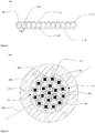
- FIG. 2 illustrates a cross sectional view of an optical fibre ribbon cable 200, in accordance with various embodiments of the present disclosure.
- the optical fibre ribbon cable 200 is a type of cable used in campus, building, data center backbone applications and the like. In general, optical fibre ribbon cable is used where high fibre counts are required. In general, the optical fibre ribbon cable has high fibre density. In addition, the optical fibre ribbon cable 200 enhances utilization of pathway and spaces for installation. In general, the optical fibre ribbon cable is suitable for installation in aerial, duct, and direct buried applications.
- the optical fibre ribbon cable 200 is manufactured and spliced rapidly. In general, the optical fibre ribbon cable allows up to 12 fibres to be spliced together at one time. Further, the optical fibre ribbon cable 200 is cost competitive.
- the optical fibre ribbon cable 200 includes 1728 optical fibres. In another embodiment of the present disclosure, the optical fibre ribbon cable 200 includes 2592 optical fibres. In yet another embodiment of the present disclosure, number of optical fibres in the optical fibre ribbon cable 200 may vary. In an embodiment of the present disclosure, the optical fibre ribbon cable 200 with 1728 optical fibres has diameter in range of about 20 millimeter to 24 millimeter. In another embodiment of the present disclosure, diameter of the optical fibre ribbon cable 200 may vary. Furthermore, diameter of the optical fibre ribbon cable 200 vary based on variation in optical fibre count.
- the optical fibre ribbon cable 200 includes a plurality of buffer tubes 206, a first layer 204, a second layer 208 and a plurality of strength members 210.
- the optical fibre ribbon cable 200 a plurality of ripcords 212, 214 and one or more water swellable yarns 216.
- the optical fibre ribbon cable 200 is defined along a longitudinal axis 202.
- longitudinal axis of an optical fibre cable is an imaginary axis along lengthwise direction of the optical fibre cable.
- the optical fibre ribbon cable 200 includes the plurality of buffer tubes 206.
- buffer tubes provide mechanical isolation to fibres present in the buffer tubes.
- Each of the plurality of buffer tubes 206 includes an optical fibre ribbon stack 218.
- the optical fibre ribbon stack 218 includes a plurality of optical fibre ribbons. In an embodiment of the present disclosure, number of plurality of optical fibre ribbons in the optical fibre ribbon stack 218 is 12. In another embodiment of the present disclosure, number of plurality of optical fibre ribbons in the optical fibre ribbon stack 218 may vary.
- Each ribbon of the plurality of optical fibre ribbons of the optical fibre ribbon stack 218 corresponds to the optical fibre ribbon 100 of FIG. 1 .
- Each ribbon of the optical fibre ribbon stack 218 includes the plurality of optical fibres 104.
- each ribbon of the optical fibre ribbon stack 218 includes 12 optical fibres.
- number of the plurality of optical fibres 104 in each ribbon of the optical fibre ribbon stack 218 may vary.
- the plurality of buffer tubes 206 correspond to loose tubes with reduced diameter.
- cross section of each of the plurality of buffer tubes 206 is circular in shape.
- shape of the plurality of buffer tubes 206 may vary.
- each of the plurality of buffer tubes 206 is similar in structure and dimensions.
- each of the plurality of buffer tubes 206 has an inner diameter and an outer diameter.
- the inner diameter of each of the plurality of buffer tubes 206 is about 4.1 millimeter corresponding to the optical fibre ribbon stack 218 with 12 optical fibre ribbons.
- the inner diameter of the plurality of buffer tubes may vary.
- each of the plurality of buffer tubes 206 is about 4.5 millimeter corresponding to the optical fibre ribbon stack 218 with 12 optical fibre ribbons. In an embodiment of the present disclosure, the outer diameter of the plurality of buffer tubes may vary. In an embodiment of the present disclosure, the plurality of buffered tubes 206 provides mechanical isolation to each ribbon of the optical fibre ribbon stack 218. In addition, the plurality of buffer tubes 206 provides protection to each ribbon of the optical fibre ribbon stack 218 from physical damage.
- the plurality of optical fibres 104 is defined by diameter. In an embodiment of the present disclosure, diameter of each of the plurality of optical fibres 104 is in range of about 160 microns to 200 microns. In another embodiment of the present disclosure, range of diameter of each of the plurality of optical fibres 104 may vary. Further, each of the plurality of optical fibres 104 is coated with acrylate material. Furthermore, acrylate material is soft material with high elongation. In an embodiment of the present disclosure, each of the plurality of optical fibres 104 with the coating of acrylate material has diameter in a range of about 160 microns to 200 microns. Furthermore, each of the plurality of optical fibres 104 is defined by the geometrical centre.
- the geometrical centres of any two adjacent optical fibres of the plurality of optical fibres 104 has a predefined distance P.
- the predefined distance P is less than 200 microns.
- the predefined distance P is in range of about 160 microns to 200 microns.
- the predefined distance P is 160 microns.
- the predefined distance P is 165 microns.
- the predefined distance P is 180 microns.
- the predefined distance P is 200 microns.
- the predefined distance P may vary.
- predefined distance P between any two adjacent optical fibres of the plurality of optical fibres 104 is equal to diameter of each of the plurality of optical fibres 104.
- predefined distance P is distance between geometrical centers of any two optical fibres lying adjacent to each other.
- Each ribbon of the optical fibre ribbon stack 218 enable mass fusion splicing of the plurality of optical fibres 104.
- mass fusion splicing technique is used to fuse a number of optical fibres in a single ribbon simultaneously.
- mass fusion splicing technique may fuse up to 12 fibres in the single ribbon at one time.
- mass fusion splicing technique fuses each of the plurality of optical fibres 104 into the optical fibre ribbon stack 218 simultaneously.
- mass fusion technique reduces installation time of the optical fibre ribbon cable 200.
- mass fusion splicing technique reduces installation labor cost.
- mass fusion splicing technique reduces dimensions of each ribbon of the optical fibre ribbon stack 218.
- each ribbon of the optical fibre ribbon stack 218 include but may not be limited to width and height. In an embodiment of the present disclosure, width of each ribbon of the optical fibre ribbon stack 218 has in range of about 1.95 millimeter to 2.55 millimeter. In another embodiment of the present disclosure, range of width of each ribbon of the optical fibre ribbon stack 218 may vary. Furthermore, each ribbon of the optical fibre ribbon stack 218 has height of in range of about 190 microns to 320 microns. In an embodiment of the present disclosure, range of height of each ribbon of the optical fibre ribbon stack 218 may vary. Moreover, each ribbon of the optical fibre ribbon stack 218 has flexibility due to acrylate matrix material used for coating.
- each ribbon of the optical fibre ribbon stack 218 can bend in non-preferential axis.
- the bending of each ribbon of the optical fibre ribbon stack 218 in non-preferential axis allows easy installation in space constraint regions.
- the bending of each ribbon of optical fibre ribbon stack 218 in non-preferential axis facilitates in the reduction of diameter of the plurality of buffer tubes 206 and diameter of the optical fibre ribbon cable 200.
- the optical fibre ribbon cable 200 maintains planarity of each ribbon of the optical fibre ribbon stack 218.
- the optical fibre ribbon cable 200 includes the first layer 204.
- the first layer 204 surrounds the plurality of buffer tubes 206.
- the first layer 204 is a layer of water blocking tape.
- water blocking tape is designed to block ingression of water inside optical fibre cables.
- the first layer 204 prevents ingression of water and moisture inside the plurality of buffer tubes 206.
- the first layer 204 has a thickness in range of about 0.1 millimeter to 0.2 millimeter. In another embodiment of the present disclosure, range of the thickness of the first layer 204 may vary.
- the optical fibre ribbon cable 200 includes the second layer 208.
- the second layer 208 surrounds the first layer 204.
- the second layer 208 is a jacket layer.
- the jacket protects the optical fibre ribbon cable 200 against crush, pressure and tensile stress.
- the second layer 208 is made of high density polyethylene material.
- the second layer 208 is made of any suitable material.
- the high density polyethylene material has density in a range of about 0.941gram/centimeter 3 - 0.971 gram/centimeter 3 .
- the second layer 208 provides stiffness, rigidity, and resistance to the optical fibre ribbon cable 200.
- the second layer 208 has a thickness in range of about 1.6 millimeter to 3 millimeter. In another embodiment of the present disclosure, range of the thickness of the second layer 208 may vary.
- the optical fibre ribbon cable 200 includes the plurality of strength members 210.
- Each of the plurality of strength members 210 is embedded in the second layer 208.
- embedded strength members provide high tensile strength and anti-buckling property to cables.
- the plurality of strength members 210 provides strength and durability to the optical fibre ribbon cable 200.
- the plurality of strength members 210 has high mechanical strength and provides protection to the optical fibre ribbon cable 200.
- strength members are used in the aerospace, automotive, marine, construction industries and the like.
- each of the plurality of strength members 210 is made of fibre reinforced plastic (FRP) material.
- FRP fibre reinforced plastic
- each of the plurality of strength members 210 is made of any other suitable material.
- each of the plurality of strength members 210 has a diameter in a range of about 0.5 millimeter to 1.6 millimeter. In another embodiment of the present disclosure, the plurality of strength members 210 has the diameter of any suitable range. In an embodiment of the present disclosure, number of the plurality of strength members 210 is 6. In another embodiment of the present disclosure, the number of the plurality of strength members 210 may vary. In an embodiment of the present disclosure, each of the plurality of strength members 210 is positioned at an equal distance to each other along the circumference of the second layer 208.
- the optical fibre ribbon cable 200 includes the plurality of ripcords 212, 214.
- the plurality of ripcords 212, 214 is positioned diametrically opposite (180 degree apart) in between the first layer 204 and second layer 208.
- the plurality of ripcords 212, 214 facilitates stripping of the second layer 208.
- each of the plurality of ripcords 212, 214 has a circular cross-section.
- a number of the plurality of ripcords 212, 214 is 2. In another embodiment of the present disclosure, the number of the plurality of ripcords 212, 214 may vary.
- the plurality of ripcords 212, 214 is made of polyester filament yarn twisted and coated with wicking material. In another embodiment of the present disclosure, the plurality of ripcords 212, 214 is made of any other suitable material.
- the optical fibre ribbon cable 200 includes the one or more water swellable yarns 216.
- the one or more water swellable yarns 216 are positioned between the plurality of buffer tubes 206.
- the one or more water swellable yarns 216 prevent ingression of water in the optical fibre ribbon cable 200.
- number of the one or more water swellable yarns is at least one. In another embodiment of the present disclosure, the number of the one or more water swellable yarns 216 may vary.
- the optical fibre ribbon cable 200 has a weight of about 332.7 kilogram per kilometer. In addition, the optical fibre ribbon cable 200 has a diameter. The diameter of the optical fibre ribbon cable 200 is about 22.9 millimeters.
- the optical fibre ribbon cable 200 provides flexibility to each ribbon of the optical fibre ribbon stack 218 and allows each ribbon of the optical fibre ribbon stack 218 to bend in non-preferential axis. The bending of each ribbon of the optical fibre ribbon stack 218 in non-preferential axis allows easy installation in space constraint regions. In addition, the bending of each ribbon of the optical fibre ribbon stack 218 in non-preferential axis reduces the diameter of the plurality of buffer tubes 206 and the diameter of the optical fibre ribbon cable 200.
- the optical fibre ribbon cable 200 includes 2592 optical fibres; however, those skilled in the art would appreciate that more or less number of optical fibres are included in the optical fibre ribbon cable 200.
- the optical fibre ribbon cable has numerous advantages over the prior art.
- the optical fibre ribbon cable is easy to install in space constraint regions.
- the optical fibre ribbon cable has reduced diameter.
- the optical fibre ribbon cable has reduced weight.
- the optical fibre ribbon cable maintains planarity of each ribbon of the optical fibre ribbon stack.
- the optical fibre ribbon cable provides flexibility to each ribbon of the optical fibre ribbon stack.
- Each ribbon of the one or more ribbon stack is capable to bend in non-preferential axis.
Landscapes
- Physics & Mathematics (AREA)
- General Physics & Mathematics (AREA)
- Optics & Photonics (AREA)
- Light Guides In General And Applications Therefor (AREA)
Applications Claiming Priority (1)
| Application Number | Priority Date | Filing Date | Title |
|---|---|---|---|
| IN201911032852 | 2019-08-14 |
Publications (1)
| Publication Number | Publication Date |
|---|---|
| EP3779547A1 true EP3779547A1 (fr) | 2021-02-17 |
Family
ID=72087883
Family Applications (1)
| Application Number | Title | Priority Date | Filing Date |
|---|---|---|---|
| EP20191007.2A Pending EP3779547A1 (fr) | 2019-08-14 | 2020-08-13 | Câble-ruban à fibres optiques |
Country Status (2)
| Country | Link |
|---|---|
| US (1) | US11300742B2 (fr) |
| EP (1) | EP3779547A1 (fr) |
Citations (4)
| Publication number | Priority date | Publication date | Assignee | Title |
|---|---|---|---|---|
| US20030223714A1 (en) * | 2002-05-31 | 2003-12-04 | Conrad Craig M. | Optical fiber ribbons having a preferential separation sequence |
| US20150030297A1 (en) * | 2013-07-26 | 2015-01-29 | Corning Optical Communicatons LLC | Fiber optic ribbon |
| US20180031792A1 (en) * | 2016-07-27 | 2018-02-01 | Prysmian S.P.A. | Flexible Optical-Fiber Ribbon |
| WO2019011417A1 (fr) * | 2017-07-11 | 2019-01-17 | Prysmian S.P.A. | Ruban de fibres optiques et son procédé de production |
Family Cites Families (14)
| Publication number | Priority date | Publication date | Assignee | Title |
|---|---|---|---|---|
| US5457762A (en) * | 1994-06-13 | 1995-10-10 | Siecor Corporation | Fiber optic ribbon |
| WO2001064596A1 (fr) * | 2000-03-03 | 2001-09-07 | Pirelli Cavi E Sistemi S.P.A. | Fibre optique a revetement colore |
| US6690867B2 (en) * | 2001-08-31 | 2004-02-10 | Corning Cable Systems Llc | Optical interconnect assemblies and methods therefor |
| EP1546786A4 (fr) * | 2002-08-29 | 2005-09-07 | Sumitomo Electric Industries | Ensemble de coeurs de fibres optiques de type ruban, procede de production de celui-ci, connecteur contenant un ensemble de coeurs de type ruban, reseau de fibres optiques contenant un ensemble de coeurs de type ruban, et systeme de cablage optique |
| JP2006081156A (ja) * | 2004-08-13 | 2006-03-23 | Fuji Photo Film Co Ltd | 画像処理装置および方法並びにプログラム |
| JP4163187B2 (ja) * | 2005-03-24 | 2008-10-08 | 古河電気工業株式会社 | 光伝送体の配線方法および光インターコネクションシステム |
| CN107076955B (zh) * | 2015-10-14 | 2020-06-23 | 住友电气工业株式会社 | 光纤素线 |
| US9880368B2 (en) * | 2016-02-02 | 2018-01-30 | Ofs Fitel, Llc | Method for high speed processing of partially bonded ribbon structures |
| US10185089B2 (en) * | 2016-09-15 | 2019-01-22 | Ofs Fitel, Llc | Splicing optical fiber cable using a mass fusion splicer having a pitch different from cable pitch |
| US10775557B2 (en) * | 2018-05-03 | 2020-09-15 | Corning Incorporated | Fiber coatings with low pullout force |
| US11287588B2 (en) * | 2018-12-12 | 2022-03-29 | Corning Incorporated | High-density optical fiber ribbon interconnect and method of making |
| US11243348B2 (en) * | 2018-12-12 | 2022-02-08 | Corning Incorporated | High-density optical fiber ribbon with cladding-strengthened glass optical fibers in a common protective coating and fiber ribbon interconnects employing same |
| US11567283B2 (en) * | 2019-02-11 | 2023-01-31 | Sterlite Technologies Limited | Optical fibre ribbon and optical fibre cables thereof |
| US10884213B1 (en) * | 2019-11-14 | 2021-01-05 | Prysmian S.P.A. | Optical-fiber ribbon with distorted sinusoidal adhesive pattern and method therefor |
-
2020
- 2020-08-13 EP EP20191007.2A patent/EP3779547A1/fr active Pending
- 2020-08-13 US US16/993,194 patent/US11300742B2/en active Active
Patent Citations (4)
| Publication number | Priority date | Publication date | Assignee | Title |
|---|---|---|---|---|
| US20030223714A1 (en) * | 2002-05-31 | 2003-12-04 | Conrad Craig M. | Optical fiber ribbons having a preferential separation sequence |
| US20150030297A1 (en) * | 2013-07-26 | 2015-01-29 | Corning Optical Communicatons LLC | Fiber optic ribbon |
| US20180031792A1 (en) * | 2016-07-27 | 2018-02-01 | Prysmian S.P.A. | Flexible Optical-Fiber Ribbon |
| WO2019011417A1 (fr) * | 2017-07-11 | 2019-01-17 | Prysmian S.P.A. | Ruban de fibres optiques et son procédé de production |
Also Published As
| Publication number | Publication date |
|---|---|
| US11300742B2 (en) | 2022-04-12 |
| US20210048589A1 (en) | 2021-02-18 |
Similar Documents
| Publication | Publication Date | Title |
|---|---|---|
| US11592632B2 (en) | Round and small diameter optical cables with a ribbon-like optical fiber structure | |
| US9971101B2 (en) | Fiber optic cable assembly | |
| US6542674B1 (en) | Fiber optic cables with strength members | |
| US6519399B2 (en) | Fiber optic cable with profiled group of optical fibers | |
| US9389381B2 (en) | Fiber optic ribbon cable | |
| US20210063661A1 (en) | Bendable optical fibre cable | |
| US11287598B2 (en) | Dual layer micro optical fiber cable | |
| WO2015195095A1 (fr) | Câble à fibres optiques à tube central | |
| EP3779547A1 (fr) | Câble-ruban à fibres optiques | |
| US11125959B2 (en) | Flat drop optical fiber cable | |
| EP3674761A1 (fr) | Câble à fibre optique unitube | |
| US11640035B1 (en) | Optical fibre cable for air blowing installation | |
| EP4202520A1 (fr) | Câble à fibres optiques avec éléments de bobine | |
| EP4206771A1 (fr) | Câble à fibre optique avec corde de déchirure mobile | |
| US20240176088A1 (en) | Optical cable with dielectric strength elements and toneable element | |
| CN116783530A (zh) | 具有可卷曲带单元和弹性体层的光纤线缆结构 |
Legal Events
| Date | Code | Title | Description |
|---|---|---|---|
| PUAI | Public reference made under article 153(3) epc to a published international application that has entered the european phase |
Free format text: ORIGINAL CODE: 0009012 |
|
| STAA | Information on the status of an ep patent application or granted ep patent |
Free format text: STATUS: THE APPLICATION HAS BEEN PUBLISHED |
|
| AK | Designated contracting states |
Kind code of ref document: A1 Designated state(s): AL AT BE BG CH CY CZ DE DK EE ES FI FR GB GR HR HU IE IS IT LI LT LU LV MC MK MT NL NO PL PT RO RS SE SI SK SM TR |
|
| AX | Request for extension of the european patent |
Extension state: BA ME |
|
| RIN1 | Information on inventor provided before grant (corrected) |
Inventor name: SHUKLA, VIKASH Inventor name: MISHRA, ATULKUMAR Inventor name: KONDAPALLI, HEMANTH Inventor name: SAHOO, KISHORE CHANDRA Inventor name: KUMAR, SRAVAN |
|
| STAA | Information on the status of an ep patent application or granted ep patent |
Free format text: STATUS: REQUEST FOR EXAMINATION WAS MADE |
|
| 17P | Request for examination filed |
Effective date: 20211117 |
|
| RBV | Designated contracting states (corrected) |
Designated state(s): AL AT BE BG CH CY CZ DE DK EE ES FI FR GB GR HR HU IE IS IT LI LT LU LV MC MK MT NL NO PL PT RO RS SE SI SK SM TR |
|
| STAA | Information on the status of an ep patent application or granted ep patent |
Free format text: STATUS: EXAMINATION IS IN PROGRESS |
|
| 17Q | First examination report despatched |
Effective date: 20220426 |