EP3779329A1 - Air conditioner - Google Patents
Air conditioner Download PDFInfo
- Publication number
- EP3779329A1 EP3779329A1 EP19785462.3A EP19785462A EP3779329A1 EP 3779329 A1 EP3779329 A1 EP 3779329A1 EP 19785462 A EP19785462 A EP 19785462A EP 3779329 A1 EP3779329 A1 EP 3779329A1
- Authority
- EP
- European Patent Office
- Prior art keywords
- refrigerant
- connection port
- dedicated connection
- filling
- air
- Prior art date
- Legal status (The legal status is an assumption and is not a legal conclusion. Google has not performed a legal analysis and makes no representation as to the accuracy of the status listed.)
- Granted
Links
Images




Classifications
-
- F—MECHANICAL ENGINEERING; LIGHTING; HEATING; WEAPONS; BLASTING
- F16—ENGINEERING ELEMENTS AND UNITS; GENERAL MEASURES FOR PRODUCING AND MAINTAINING EFFECTIVE FUNCTIONING OF MACHINES OR INSTALLATIONS; THERMAL INSULATION IN GENERAL
- F16L—PIPES; JOINTS OR FITTINGS FOR PIPES; SUPPORTS FOR PIPES, CABLES OR PROTECTIVE TUBING; MEANS FOR THERMAL INSULATION IN GENERAL
- F16L37/00—Couplings of the quick-acting type
- F16L37/22—Couplings of the quick-acting type in which the connection is maintained by means of balls, rollers or helical springs under radial pressure between the parts
- F16L37/23—Couplings of the quick-acting type in which the connection is maintained by means of balls, rollers or helical springs under radial pressure between the parts by means of balls
-
- F—MECHANICAL ENGINEERING; LIGHTING; HEATING; WEAPONS; BLASTING
- F25—REFRIGERATION OR COOLING; COMBINED HEATING AND REFRIGERATION SYSTEMS; HEAT PUMP SYSTEMS; MANUFACTURE OR STORAGE OF ICE; LIQUEFACTION SOLIDIFICATION OF GASES
- F25B—REFRIGERATION MACHINES, PLANTS OR SYSTEMS; COMBINED HEATING AND REFRIGERATION SYSTEMS; HEAT PUMP SYSTEMS
- F25B13/00—Compression machines, plants or systems, with reversible cycle
-
- F—MECHANICAL ENGINEERING; LIGHTING; HEATING; WEAPONS; BLASTING
- F25—REFRIGERATION OR COOLING; COMBINED HEATING AND REFRIGERATION SYSTEMS; HEAT PUMP SYSTEMS; MANUFACTURE OR STORAGE OF ICE; LIQUEFACTION SOLIDIFICATION OF GASES
- F25B—REFRIGERATION MACHINES, PLANTS OR SYSTEMS; COMBINED HEATING AND REFRIGERATION SYSTEMS; HEAT PUMP SYSTEMS
- F25B45/00—Arrangements for charging or discharging refrigerant
-
- F—MECHANICAL ENGINEERING; LIGHTING; HEATING; WEAPONS; BLASTING
- F25—REFRIGERATION OR COOLING; COMBINED HEATING AND REFRIGERATION SYSTEMS; HEAT PUMP SYSTEMS; MANUFACTURE OR STORAGE OF ICE; LIQUEFACTION SOLIDIFICATION OF GASES
- F25B—REFRIGERATION MACHINES, PLANTS OR SYSTEMS; COMBINED HEATING AND REFRIGERATION SYSTEMS; HEAT PUMP SYSTEMS
- F25B9/00—Compression machines, plants or systems, in which the refrigerant is air or other gas of low boiling point
- F25B9/002—Compression machines, plants or systems, in which the refrigerant is air or other gas of low boiling point characterised by the refrigerant
-
- F—MECHANICAL ENGINEERING; LIGHTING; HEATING; WEAPONS; BLASTING
- F25—REFRIGERATION OR COOLING; COMBINED HEATING AND REFRIGERATION SYSTEMS; HEAT PUMP SYSTEMS; MANUFACTURE OR STORAGE OF ICE; LIQUEFACTION SOLIDIFICATION OF GASES
- F25B—REFRIGERATION MACHINES, PLANTS OR SYSTEMS; COMBINED HEATING AND REFRIGERATION SYSTEMS; HEAT PUMP SYSTEMS
- F25B2345/00—Details for charging or discharging refrigerants; Service stations therefor
- F25B2345/001—Charging refrigerant to a cycle
-
- F—MECHANICAL ENGINEERING; LIGHTING; HEATING; WEAPONS; BLASTING
- F25—REFRIGERATION OR COOLING; COMBINED HEATING AND REFRIGERATION SYSTEMS; HEAT PUMP SYSTEMS; MANUFACTURE OR STORAGE OF ICE; LIQUEFACTION SOLIDIFICATION OF GASES
- F25B—REFRIGERATION MACHINES, PLANTS OR SYSTEMS; COMBINED HEATING AND REFRIGERATION SYSTEMS; HEAT PUMP SYSTEMS
- F25B2345/00—Details for charging or discharging refrigerants; Service stations therefor
- F25B2345/002—Collecting refrigerant from a cycle
-
- F—MECHANICAL ENGINEERING; LIGHTING; HEATING; WEAPONS; BLASTING
- F25—REFRIGERATION OR COOLING; COMBINED HEATING AND REFRIGERATION SYSTEMS; HEAT PUMP SYSTEMS; MANUFACTURE OR STORAGE OF ICE; LIQUEFACTION SOLIDIFICATION OF GASES
- F25B—REFRIGERATION MACHINES, PLANTS OR SYSTEMS; COMBINED HEATING AND REFRIGERATION SYSTEMS; HEAT PUMP SYSTEMS
- F25B2345/00—Details for charging or discharging refrigerants; Service stations therefor
- F25B2345/006—Details for charging or discharging refrigerants; Service stations therefor characterised by charging or discharging valves
-
- F—MECHANICAL ENGINEERING; LIGHTING; HEATING; WEAPONS; BLASTING
- F25—REFRIGERATION OR COOLING; COMBINED HEATING AND REFRIGERATION SYSTEMS; HEAT PUMP SYSTEMS; MANUFACTURE OR STORAGE OF ICE; LIQUEFACTION SOLIDIFICATION OF GASES
- F25B—REFRIGERATION MACHINES, PLANTS OR SYSTEMS; COMBINED HEATING AND REFRIGERATION SYSTEMS; HEAT PUMP SYSTEMS
- F25B2400/00—Component parts or details not otherwise provided for in this subclass
- F25B2400/12—Inflammable refrigerants
Definitions
- a refrigerant region with combustible density may be formed. If an ignition source is present near the refrigerant region of combustible density, the refrigerant may be ignited. To avoid occurrence of such ignition, it is necessary to prevent the refrigerant region with combustible density from being formed. Further, to prevent the refrigerant region with combustible density from being formed, it is necessary to suppress a leakage amount to a degree that does not form the refrigerant region with combustible density in an air-conditioned space even if leakage of the refrigerant occurs.
- the leaked refrigerant may permeate the machine chamber storing an electric component that may serve as an ignition source.
- the compressor 11 sucks low-temperature low-pressure refrigerant, compresses the sucked refrigerant, and discharges high-temperature high-pressure refrigerant.
- the compressor 11 includes, for example, an inverter compressor that changes a compressor frequency to control a capacity as a feed amount per unit time.
- the pipe 1b connected to the refrigerant flow switching device 12 is connected to the outdoor unit-side connection port 16a.
- the indoor/outdoor connection pipe 4 connected to the indoor unit 2 is connected to the gas pipe-side connection port 16b.
- a hose or the like of the non-illustrated vacuum pump for evacuation is connected to the evacuation-dedicated connection port 17.
- the protrusion 31 is provided so as to push the pin 21a that is provided at the valve core 21 inside the charge valve 20 when the charge valve 20 is connected to the quick joint 30.
- the protrusion 31 opens the valve core 21 to allow the fluid to pass through the charge valve 20.
- the balls 32 are regulated in movement in the outer peripheral direction (arrow X direction) by being covered with the sleeve 34. At this time, the balls 32 are regulated in movement while each of the balls 32 partially protrudes to the internal space. In contrast, when the spring 33 is contracted and the sleeve 34 is moved to the direction opposite to the opening port 30a side, the regulation of the movement of the balls 32 by the sleeve 34 is released. As a result, the balls 32 become movable in the outer peripheral direction (arrow X direction).
- the hose connected to the vacuum pump is connected to the evacuation-dedicated connection port 17, and evacuation is then performed. After the evacuation ends, the liquid pipe closing valve 15 and the gas pipe closing valve 16 are opened to allow the refrigerant to flow into the indoor unit 2. As a result, the air-conditioning apparatus 100 is turned to be operable.
- the outdoor unit 201 includes the compressor 11, the refrigerant flow switching device 12, and the expansion valve 14 that are accommodated in the machine chamber 1A, and the outdoor heat exchanger 13 accommodated in the air-sending chamber 1B.
- the outdoor unit 201 further includes the liquid pipe closing valve 15, the gas pipe closing valve 16, the evacuation-dedicated connection port 17, and the refrigerant filling-dedicated connection port 18.
Landscapes
- Engineering & Computer Science (AREA)
- General Engineering & Computer Science (AREA)
- Mechanical Engineering (AREA)
- Physics & Mathematics (AREA)
- Thermal Sciences (AREA)
- Other Air-Conditioning Systems (AREA)
- Compression-Type Refrigeration Machines With Reversible Cycles (AREA)
- Valve Housings (AREA)
Abstract
Description
- The present disclosure relates to an air-conditioning apparatus in which combustible refrigerant is used.
- In a related art air-conditioning apparatus, R410A that is hydrofluorocarbon (HFC) refrigerant is mainly used as refrigerant filled in a refrigerant circuit. Unlike hydrochlorofluorocarbon (HCFC) refrigerant such as R22 that has hitherto been used, ozone depletion potential (ODP) of R410A is zero. Therefore, R410A does not destroy an ozone layer. However, R410A tends to increase global warming potential (GWP). Accordingly, in recent years, switching of the refrigerant from the HFC refrigerant having high GWP such as R410A to the HFC refrigerant having low GWP such as R32 is under way as part of efforts to prevent global warming.
- Many of the refrigerant having the low GWP are typically combustible. Therefore, in a case of using the refrigerant having the low GWP, it is necessary to pay attention to leakage of the refrigerant into the air. The combustibility ranges from low combustibility to high combustibility. Here, the refrigerant having the combustibility is generally referred to as combustible refrigerant.
- If the combustible refrigerant is leaked into a room and the leaked refrigerant is stagnated in the room without being diffused, a refrigerant region with combustible density may be formed. If an ignition source is present near the refrigerant region of combustible density, the refrigerant may be ignited. To avoid occurrence of such ignition, it is necessary to prevent the refrigerant region with combustible density from being formed. Further, to prevent the refrigerant region with combustible density from being formed, it is necessary to suppress a leakage amount to a degree that does not form the refrigerant region with combustible density in an air-conditioned space even if leakage of the refrigerant occurs.
- In a case where the refrigerant more than a necessary refrigerant amount is filled and leakage of the refrigerant occurs in the air-conditioning apparatus, the refrigerant region with combustible density may be formed as described above. Under such circumstances,
Patent Literature 1 discloses an air-conditioning apparatus in which a refrigerant filling connection port is attached to a closing valve provided with a flare joint that connects a pipe connected to an indoor unit and a pipe connected to an outdoor unit, and a shape of the connection port is made different depending on a type of the used refrigerant, thereby preventing erroneous filling of the refrigerant. The refrigerant filling connection port is used for evacuation of the air inside the indoor unit and indoor/outdoor connection pipes connecting the outdoor unit and the indoor unit, in addition to filling of the refrigerant. -
Patent Literature 2 discloses an air-conditioning apparatus in which a valve provided with a flare joint that connects a pipe connected to an indoor unit and a pipe connected to an outdoor unit is disposed inside a machine chamber of the outdoor unit. The valve is also provided with a connection port shared for filling of the refrigerant and for evacuation. -
- Patent Literature 1: Japanese Unexamined Patent Application Publication No.
H7-269904 - Patent Literature 2: Japanese Unexamined Patent Application Publication No.
2010-25459 - In the air-conditioning apparatus disclosed in
Patent Literature 1, the refrigerant filling connection port is provided outside the machine chamber of the outdoor unit because the refrigerant filling connection port is also used for evacuation of the indoor unit and the indoor/outdoor connection pipes. Accordingly, anybody can easily access the refrigerant filling connection port, and even a worker not having advanced technical knowledge can fill the refrigerant. - When the worker not having technical knowledge fills the refrigerant, however, erroneous work such as overfilling may occur. In a case where the refrigerant having high combustibility such as R290 (propane) is used as the refrigerant and the refrigerant is overfilled and leaked, if leakage of the refrigerant occurs in the closed space, possibility that density of the refrigerant in a partial region of the space reaches combustible density is increased. This may deteriorate safety.
- Further, if the refrigerant is leaked from the flare joint that connects the indoor/outdoor connection pipes and is disposed inside the machine chamber as disclosed in
Patent Literature 2, the leaked refrigerant may permeate the machine chamber storing an electric component that may serve as an ignition source. - The present disclosure is made in consideration of the above-described issues, and an object thereof is to provide an air-conditioning apparatus that can prevent erroneous work at the time of filling refrigerant, and can prevent leakage of combustible refrigerant by the erroneous work.
- An air-conditioning apparatus of an embodiment of the present disclosure includes a refrigerant circuit that is formed of an outdoor unit and an indoor unit connected through indoor/outdoor connection pipes. The outdoor unit includes a compressor, an outdoor heat exchanger, and an expansion valve. The indoor unit includes an indoor heat exchanger. Combustible refrigerant is used as refrigerant flowing through the refrigerant circuit. The outdoor unit includes a refrigerant filling-dedicated connection port to fill the refrigerant and an evacuation-dedicated connection port to evacuate the refrigerant inside the refrigerant circuit. The refrigerant filling-dedicated connection port is provided inside a machine chamber that accommodates the compressor and the expansion valve, and the evacuation-dedicated connection port is provided outside the machine chamber. Advantageous Effects of Invention
- According to the embodiment of the present disclosure, the refrigerant filling-dedicated connection port and the evacuation-dedicated connection port are separately provided, and the refrigerant filling-dedicated connection port is provided inside the machine chamber. This makes it possible to prevent erroneous work at the time of filling the refrigerant, and to suppress leakage of combustible refrigerant due to the erroneous work.
-
- [
Fig. 1] Fig. 1 is a schematic view illustrating an exemplary configuration of an air-conditioning apparatus according toEmbodiment 1. - [
Fig. 2] Fig. 2 is a perspective view illustrating an exemplary appearance of an outdoor unit illustrated inFig. 1 . - [
Fig. 3] Fig. 3 is a schematic cross-sectional view illustrating an exemplary structure of a gas pipe closing valve including an evacuation-dedicated connection port illustrated inFig. 1 . - [
Fig. 4] Fig. 4 is a schematic view illustrating an exemplary shape of a refrigerant filling-dedicated connection port illustrated inFig. 1 . - [
Fig. 5] Fig. 5 is a schematic cross-sectional view illustrating an exemplary structure of a charge valve forming the refrigerant filling-dedicated connection port illustrated inFig. 4 . - [
Fig. 6] Fig. 6 is a schematic view illustrating an exemplary configuration of a tool to be connected to the refrigerant filling-dedicated connection port illustrated inFig. 4 . - [
Fig. 7] Fig. 7 is a schematic cross-sectional view illustrating an exemplary structure of a quick joint illustrated inFig. 6 . - [
Fig. 8] Fig. 8 is a schematic cross-sectional view illustrating a state where the charge valve inFig. 5 and the quick joint inFig. 7 are connected. - [
Fig. 9] Fig. 9 is a schematic view illustrating an exemplary configuration of an air-conditioning apparatus according toEmbodiment 2. - [
Fig. 10] Fig. 10 is a schematic cross-sectional view illustrating an exemplary structure of a housing unit illustrated inFig. 9 . - [
Fig. 11] Fig. 11 is a schematic view illustrating an exemplary appearance of an outdoor unit when a lid inFig. 10 is viewed from a front side. - [
Fig. 12] Fig. 12 is a schematic view illustrating an exemplary structure of a cap to be attached to a charge valve forming a refrigerant filling-dedicated connection port illustrated inFig. 9 . - [
Fig. 13] Fig. 13 is a schematic view illustrating an exemplary configuration of an air-conditioning apparatus according toEmbodiment 3. - [
Fig. 14] Fig. 14 is a schematic view illustrating an exemplary appearance of anoutdoor unit 301 illustrated inFig. 13 . - [
Fig. 15] Fig. 15 is a schematic view illustrating an exemplary structure of a cap to be attached to a charge valve illustrated inFig. 13 . - An air-conditioning apparatus according to
Embodiment 1 of the present disclosure is described below.Fig. 1 is a schematic view illustrating an exemplary configuration of an air-conditioning apparatus 100 according toEmbodiment 1. As illustrated inFig. 1 , the air-conditioning apparatus 100 is, for example, a split type air-conditioning apparatus, and includes anoutdoor unit 1 and anindoor unit 2. Theoutdoor unit 1 and theindoor unit 2 are connected by indoor/outdoor connection pipes - The
outdoor unit 1 includes acompressor 11, a refrigerantflow switching device 12, anoutdoor heat exchanger 13, and anexpansion valve 14. An internal space of theoutdoor unit 1 is divided into amachine chamber 1A and an air-sendingchamber 1B. Thecompressor 11, the refrigerantflow switching device 12, and theexpansion valve 14 are accommodated in themachine chamber 1A. Theoutdoor heat exchanger 13 is accommodated in the air-sendingchamber 1B. - The
compressor 11 sucks low-temperature low-pressure refrigerant, compresses the sucked refrigerant, and discharges high-temperature high-pressure refrigerant. Thecompressor 11 includes, for example, an inverter compressor that changes a compressor frequency to control a capacity as a feed amount per unit time. - The refrigerant
flow switching device 12 is, for example, a four-way valve, and switches a flowing direction of the refrigerant to switch operation between cooling operation and heating operation. During the cooling operation, the refrigerantflow switching device 12 is switched to connect a discharge side of thecompressor 11 and theoutdoor heat exchanger 13 as illustrated by a solid line inFig. 1 . During the heating operation, the refrigerantflow switching device 12 is switched to connect the discharge side of thecompressor 11 and anindoor heat exchanger 25 of theindoor unit 2 as illustrated by a dashed line inFig. 1 . - The
outdoor heat exchanger 13 causes heat exchange to be performed between outdoor air supplied by a non-illustrated fan or the like and the refrigerant. During the cooling operation, theoutdoor heat exchanger 13 functions as a condenser that dissipates heat of the refrigerant to the outdoor air, thereby condensing the refrigerant. During the heating operation, theoutdoor heat exchanger 13 functions as an evaporator that evaporates the refrigerant to cool the outdoor air by vaporization heat at the time of evaporation. - The
expansion valve 14 expands the refrigerant. Theexpansion valve 14 includes a valve, an opening degree of which is controllable, such as an electronic expansion valve. - The
outdoor unit 1 further includes a liquidpipe closing valve 15, a gaspipe closing valve 16, an evacuation-dedicatedconnection port 17, and a refrigerant filling-dedicatedconnection port 18. The liquidpipe closing valve 15 is attached to apipe 1a between theexpansion valve 14 and theindoor heat exchanger 25 of theindoor unit 2, and opens/closes a flow path between theexpansion valve 14 and theindoor heat exchanger 25. The gaspipe closing valve 16 is attached to apipe 1b between the refrigerantflow switching device 12 and theindoor heat exchanger 25, and opens/closes a flow path between the refrigerantflow switching device 12 and theindoor heat exchanger 25. - The evacuation-dedicated
connection port 17 is a connection port to which a vacuum pump is connected in evacuation. The evacuation-dedicatedconnection port 17 is disposed outside anouter shell 10 of themachine chamber 1A. InEmbodiment 1, the evacuation-dedicatedconnection port 17 is provided in the gaspipe closing valve 16. - The refrigerant filling-dedicated
connection port 18 is a connection port used to fill the refrigerant in the refrigerant circuit. The refrigerant filling-dedicatedconnection port 18 is disposed inside themachine chamber 1A. The refrigerant filling-dedicatedconnection port 18 is attached to apipe 1c that connects the refrigerantflow switching device 12 and a suction side of thecompressor 11. - The attachment position of the refrigerant filling-dedicated
connection port 18 is not limited thereto, and the refrigerant filling-dedicatedconnection port 18 may be attached to thepipe 1b that connects the gaspipe closing valve 16 and the refrigerantflow switching device 12. In other words, taking into consideration a case where the refrigerantflow switching device 12 is not provided, it is sufficient for the refrigerant filling-dedicatedconnection port 18 to be attached to a pipe that connects the suction side of thecompressor 11 and the gaspipe closing valve 16. -
Fig. 2 is a perspective view illustrating an exemplary appearance of theoutdoor unit 1 illustrated inFig. 1 . As illustrated inFig. 2 , theoutdoor unit 1 has, for example, the rectangularouter shell 10, and a part of theouter shell 10 is detachable. The evacuation-dedicatedconnection port 17 is disposed to be exposed to outside of theouter shell 10. In contrast, the refrigerant filling-dedicatedconnection port 18 is disposed in theunillustrated machine chamber 1A inside theoutdoor unit 1 to be exposed when a part of theouter shell 10 is detached. - The
indoor unit 2 illustrated inFig. 1 includes theindoor heat exchanger 25. Theindoor heat exchanger 25 causes heat exchange to be performed between air supplied by an unillustrated fan or the like and the refrigerant. As a result, heating air or cooling air to be supplied to an indoor space is generated. Theindoor heat exchanger 25 functions as an evaporator that cools the air in an air-conditioned space to perform cooling during the cooling operation. Further, theindoor heat exchanger 25 functions as a condenser that heats the air in the air-conditioned space to perform heating during the heating operation. -
Fig. 3 is a schematic cross-sectional view illustrating an exemplary structure of the gaspipe closing valve 16 including the evacuation-dedicatedconnection port 17 illustrated inFig. 1 . The gaspipe closing valve 16 is provided with an outdoor unit-side connection port 16a, a gas pipe-side connection port 16b, and the evacuation-dedicatedconnection port 17. - The
pipe 1b connected to the refrigerantflow switching device 12 is connected to the outdoor unit-side connection port 16a. The indoor/outdoor connection pipe 4 connected to theindoor unit 2 is connected to the gas pipe-side connection port 16b. A hose or the like of the non-illustrated vacuum pump for evacuation is connected to the evacuation-dedicatedconnection port 17. - The evacuation-dedicated
connection port 17 is provided with a screw part on an outer periphery, and is provided with a conicalfront end part 17a inclined at about 45 degrees, as with a related art port. A cylindrical internal space having the screw part is provided at a center of the evacuation-dedicatedconnection port 17, and avalve core 17b is disposed inside the internal space. - When the hose of the vacuum pump is not connected, a
cap 17c is fastened to the evacuation-dedicatedconnection port 17 by a screw. An inner surface of thecap 17c is formed in a conical shape inclined at about 45 degrees to correspond to thefront end part 17a. As a result, a seal surface is formed between thecap 17c and thefront end part 17a of the evacuation-dedicatedconnection port 17, which prevents leakage of the refrigerant. - Further, the gas
pipe closing valve 16 is provided with avalve part 16c and anopening port 16d. Thevalve part 16c opens/closes a refrigerant flow path between the refrigerantflow switching device 12 and the indoor/outdoor connection pipe 4. Theopening port 16d allows for operation of thevalve part 16c. When thevalve part 16c is not operated, theopening port 16d is closed by aprotection cap 16e. -
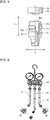
Fig. 4 is a schematic view illustrating an exemplary shape of the refrigerant filling-dedicatedconnection port 18 illustrated inFig. 1 .Fig. 5 is a schematic cross-sectional view illustrating an exemplary structure of acharge valve 20 forming the refrigerant filling-dedicatedconnection port 18 illustrated inFig. 4 . A quick joint 30 is connected to the refrigerant filling-dedicatedconnection port 18 when the refrigerant circuit is filled in the refrigerant. The quick joint 30 is attached to a front end of a hose that is connected to a tool such as a gage manifold. As illustrated inFig. 4 , the refrigerant filling-dedicatedconnection port 18 includes thecharge valve 20 and is provided on thepipe 1c. Thecharge valve 20 is joined to thepipe 1c by abifurcation pipe 18a to bifurcate the flow of the refrigerant flowing through thepipe 1c. - As illustrated in
Fig. 4 andFig. 5 , thecharge valve 20 has a cylindrical shape, and is provided with anopening port 20a to which the quick joint 30 is connected. A valve-side screw part 20b is provided on an inner periphery of theopening port 20a. - A cylindrical internal space through which fluid passes is provided at a center of the
charge valve 20, and avalve core 21 is disposed inside the internal space. Apin 21a extending in an insertion/removal direction (arrow Y direction inFig. 5 ) is provided on theopening port 20a side of thevalve core 21. When the quick joint 30 is connected to thecharge valve 20, thepin 21a is pressed and thevalve core 21 is accordingly opened, which enables the fluid to pass through thecharge valve 20. - The
charge valve 20 is provided with agroove 20c along the outer periphery. Thegroove 20c is to fix the quick joint 30 when the quick joint 30 is connected. - Further, a
cap 22 is detachably attached to theopening port 20a. Thecap 22 is made of, for example, a metal material. When the quick joint 30 is not connected to thecharge valve 20, thecap 22 is attached to theopening port 20a. Thecap 22 is provided with a cap-side screw part 22a at a position corresponding to the valve-side screw part 20b of thecharge valve 20. When the cap-side screw part 22a and the valve-side screw part 20b of thecharge valve 20 are screwed to each other, thecap 22 closely contacts with thecharge valve 20. -
Fig. 6 is a schematic view illustrating an exemplary configuration of atool 50 to be connected to the refrigerant filling-dedicatedconnection port 18 illustrated inFig. 4 .Fig. 6 illustrates an example in a case where a gage manifold is used as thetool 50. - A
hose 51 is attached to the gage manifold as thetool 50. The quick joint 30 that connects thehose 51 to thecharge valve 20 of the refrigerant filling-dedicatedconnection port 18 is attached to a front end of thehose 51. In particular, inEmbodiment 1, a gage manifold for combustible refrigerant is used. In this case, a connected portion between the gage manifold for the combustible refrigerant and thehose 51 and a connected portion between thehose 51 and the quick joint 30 are fastened by a tool such as a spanner, unlike a related art connected portion manually fastened. -
Fig. 7 is a schematic cross-sectional view illustrating an exemplary structure of the quick joint 30 illustrated inFig. 6 . As illustrated inFig. 7 , the quick joint 30 has a cylindrical shape, and is provided with anopening port 30a to which thecharge valve 20 illustrated inFig. 4 andFig. 5 is connected. A cylindrical internal space through which the fluid passes is provided at a center of the quick joint 30, and a rod-shapedprotrusion 31 that protrudes in an insertion/removal direction (arrow Y direction inFig. 7 ) is provided in the internal space. - The
protrusion 31 is provided so as to push thepin 21a that is provided at thevalve core 21 inside thecharge valve 20 when thecharge valve 20 is connected to the quick joint 30. When thecharge valve 20 is connected to the quick joint 30, theprotrusion 31 opens thevalve core 21 to allow the fluid to pass through thecharge valve 20. - On the outer periphery on the
opening port 30a side of the quick joint 30, throughholes 30b are bored, andballs 32 as locking parts are provided in the respective throughholes 30b. Theballs 32 are movable in a radial direction (arrow X direction) of the quick joint 30 inside the respective throughholes 30b. Each of the throughholes 30b has a structure in which thecorresponding ball 32 does not fall in the internal space. - Further, on the outer periphery on the
opening port 30a side of the quick joint 30, aspring 33 is wound and asleeve 34 is provided to cover theballs 32. Thesleeve 34 is slidable in the insertion/removal direction (arrow Y direction) on the outer periphery of the quick joint 30 along with expansion and contraction of thespring 33. - The
balls 32 are regulated in movement in the outer peripheral direction (arrow X direction) by being covered with thesleeve 34. At this time, theballs 32 are regulated in movement while each of theballs 32 partially protrudes to the internal space. In contrast, when thespring 33 is contracted and thesleeve 34 is moved to the direction opposite to theopening port 30a side, the regulation of the movement of theballs 32 by thesleeve 34 is released. As a result, theballs 32 become movable in the outer peripheral direction (arrow X direction). -
Fig. 8 is a schematic cross-sectional view illustrating a state where thecharge valve 20 inFig. 5 and the quick joint 30 inFig. 7 are connected. First, as illustrated inFig. 8 , in a case where the quick joint 30 is connected to thecharge valve 20, thecharge valve 20 is inserted into the quick joint 30. - At this time, the
sleeve 34 of the quick joint 30 is slid in the direction opposite to theopening port 30a to contract thespring 33. As a result, the regulation of the movement of theballs 32 is released along with movement of thesleeve 34. Further, when thecharge valve 20 is inserted into the quick joint 30, force is applied to theballs 32 from the internal space side of the quick joint 30, and theballs 32 are moved in the outer peripheral direction by the force. - When the
charge valve 20 is correctly inserted into the quick joint 30, the position of thegroove 20c of thecharge valve 20 and the positions of theballs 32 of the quick joint 30 are coincident with each other, and theballs 32 protrude to the internal space side and engage with thegroove 20c. Thereafter, when thesleeve 34 is slid toward theopening port 30a, the movement of theballs 32 is regulated, and theballs 32 are locked to thegroove 20c. As a result, the quick joint 30 is fixed to thecharge valve 20. - Further, when the
charge valve 20 is inserted into the quick joint 30, thepin 21a of thevalve core 21 in thecharge valve 20 is pushed by theprotrusion 31 of the quick joint 30. Therefore, thevalve core 21 is released, and the fluid can pass through the internal spaces of both of thecharge valve 20 and the quick joint 30. - To detach the quick joint 30 from the
charge valve 20, thesleeve 34 is slid in the direction opposite to theopening port 30a to contract thespring 33, and the regulation of the movement of theballs 32 is accordingly released. When the quick joint 30 is pulled out in this state, theballs 32 engaged with thegroove 20c are moved in the outer peripheral direction by force from the internal space side, and are disengaged from thegroove 20c. - Further, when the quick joint 30 is pulled out from the
charge valve 20, theprotrusion 31 is moved in the direction opposite to theopening port 30a, and thepin 21a of thevalve core 21 is not pushed by theprotrusion 31. As a result, thevalve core 21 is closed. Note that the quick joint 30 includes a non-illustrated valve, and the valve is also closed when the quick joint 30 is pulled out from thecharge valve 20. As a result, flowing of the fluid to the internal spaces of both of thecharge valve 20 and the quick joint 30 is blocked. - To newly install the air-
conditioning apparatus 100, theoutdoor unit 1 and theindoor unit 2 are first connected by the indoor/outdoor connection pipes pipe closing valve 15 and the gaspipe closing valve 16 of theoutdoor unit 1 are closed. - The hose connected to the vacuum pump is connected to the evacuation-dedicated
connection port 17, and evacuation is then performed. After the evacuation ends, the liquidpipe closing valve 15 and the gaspipe closing valve 16 are opened to allow the refrigerant to flow into theindoor unit 2. As a result, the air-conditioning apparatus 100 is turned to be operable. - As described above, the tool such as the gage manifold similar to the tool in the existing air-conditioning apparatus can be used in the evacuation. This facilitates the installation work without requiring a special work tool in the evacuation.
- For example, in a case where the refrigerant inside the air-
conditioning apparatus 100 is extracted for repair, replacement, or the like of a refrigerant circuit component, the refrigerant is refilled in the air-conditioning apparatus 100. Further, for example, in a case where the indoor/outdoor connection pipes conditioning apparatus 100. - In a case where filling of the refrigerant is necessary as described above, a part of the
outer shell 10 of themachine chamber 1A is first detached to expose the refrigerant filling-dedicatedconnection port 18 provided inside themachine chamber 1A to the outside. Further, in a state where the refrigerant filling-dedicatedconnection port 18 is accessible, thetool 50 such as the gage manifold to fill the combustible refrigerant is connected to the refrigerant filling-dedicatedconnection port 18, and the refrigerant is filled in the air-conditioning apparatus 100. - At this time, a refrigerant tank and the
hose 51 with the quick joint 30 attached at the front end are connected to the gage manifold as thetool 50. Further, after the air inside the gage manifold and thehose 51 is pushed out by the refrigerant and is exhausted, the quick joint 30 at the front end of thehose 51 is connected to thecharge valve 20 of the refrigerant filling-dedicatedconnection port 18, and the refrigerant is filled in the air-conditioning apparatus 100. The refrigerant is filled in the air-conditioning apparatus 100 while a filling amount is measured. - As described above, when the quick joint 30 is connected to the
charge valve 20, the quick joint 30 is pushed into thecharge valve 20 to immediately establish connection. Accordingly, as compared with the existing connection method by a screw, it is possible to suppress a leakage amount of the refrigerant in connection. - Note that a left-hand screw is used for a mouthpiece of the tank of the combustible refrigerant such as R290 (propane). In contrast, a right-hand screw is used for a mouthpiece of the tank of noncombustible refrigerant such as R410A. As described above, a fastening direction of the screw used for the mouthpiece of the refrigerant tank is different depending on the combustibility of the refrigerant, which prevents mix-up of the refrigerant.
- As described above, in
Embodiment 1, thecharge valve 20 that is different from the existing valve is used as the valve of the refrigerant filling-dedicatedconnection port 18. As a result, a worker other than a worker having technical knowledge cannot easily work, which makes it possible to prevent erroneous work at the time of filling the refrigerant. - Further, in
Embodiment 1, thecharge valve 20 is used for the refrigerant filling-dedicatedconnection port 18, and the quick joint 30 is used for thetool 50 that is used at the time of filling the refrigerant. This makes it possible to reduce the leakage amount of the refrigerant in attachment and detachment as compared with connection by the screw in the existing technology. - As described above, in the air-
conditioning apparatus 100 according toEmbodiment 1, the evacuation-dedicatedconnection port 17 and the refrigerant filling-dedicatedconnection port 18 are separately provided, the evacuation-dedicatedconnection port 17 is provided outside themachine chamber 1A of theoutdoor unit 1, and the refrigerant filling-dedicatedconnection port 18 is provided inside themachine chamber 1A. To access the refrigerant filling-dedicatedconnection port 18, it is necessary to detach a part of theouter shell 10 of themachine chamber 1A. As a result, the refrigerant is filled by the procedure different from the procedure in the existing technology. This makes it possible to prevent anybody from easily filling the refrigerant. Since erroneous work by the worker other than the worker having technical knowledge is prevented, it is possible to prevent leakage of the refrigerant at the time of filling the refrigerant. - Further, in the air-
conditioning apparatus 100 according toEmbodiment 1, thecharge valve 20 to which the quick joint 30 provided to thetool 50 is connected is used as the refrigerant filling-dedicatedconnection port 18. Thus, since the worker uses the tool different from the tool in the related art technology to fill the refrigerant by the work procedure different from the related art work procedure, the refrigerant can be filled only by the worker having advanced technical knowledge. This makes it possible to prevent overfilling of the refrigerant and erroneous filling of the different type of the refrigerant. In addition, as compared with the connection method by the screw used in the existing air-conditioning apparatus, the leakage amount of the refrigerant when the quick joint 30 is attached/detached can be suppressed, which makes it possible to prevent the leaked refrigerant from permeating themachine chamber 1A. - Further, in the air-
conditioning apparatus 100 according toEmbodiment 1, the refrigerant filling-dedicatedconnection port 18 is attached to thepipe compressor 11 and the gaspipe closing valve 16. Therefore, the refrigerant filling-dedicatedconnection port 18 is provided on thecompressor 11 side of the gaspipe closing valve 16 provided outside theoutdoor unit 1, namely, the refrigerant filling-dedicatedconnection port 18 is provided inside theoutdoor unit 1. In other words, it is necessary to access the inside of theoutdoor unit 1 to access the refrigerant filling-dedicatedconnection port 18. This makes it possible to prevent anybody from easily filling the refrigerant. - Next,
Embodiment 2 of the present disclosure is described.Embodiment 2 is different fromEmbodiment 1 in that the refrigerant filling-dedicatedconnection port 18 is housed in a housing unit inside themachine chamber 1A. InEmbodiment 2, components common to the components inEmbodiment 1 are denoted by the same reference numerals, and detailed description of the components is omitted. -
Fig. 9 is a schematic view illustrating an exemplary configuration of an air-conditioning apparatus 200 according toEmbodiment 2. As illustrated inFig. 9 , the air-conditioning apparatus 200 includes anoutdoor unit 201 and theindoor unit 2. Theoutdoor unit 201 and theindoor unit 2 are connected by the indoor/outdoor connection pipes - As in
Embodiment 1, theoutdoor unit 201 includes thecompressor 11, the refrigerantflow switching device 12, and theexpansion valve 14 that are accommodated in themachine chamber 1A, and theoutdoor heat exchanger 13 accommodated in the air-sendingchamber 1B. Theoutdoor unit 201 further includes the liquidpipe closing valve 15, the gaspipe closing valve 16, the evacuation-dedicatedconnection port 17, and the refrigerant filling-dedicatedconnection port 18. - As in
Embodiment 1, the evacuation-dedicatedconnection port 17 is disposed outside theouter shell 10 of themachine chamber 1A, and is provided in the gaspipe closing valve 16. The refrigerant filling-dedicatedconnection port 18 is disposed inside themachine chamber 1A. InEmbodiment 2, the refrigerant filling-dedicatedconnection port 18 is attached to thepipe 1b that connects the gaspipe closing valve 16 and the refrigerantflow switching device 12. - The attachment position of the refrigerant filling-dedicated
connection port 18 is not limited thereto, and the refrigerant filling-dedicatedconnection port 18 may be attached to thepipe 1c that connects the refrigerantflow switching device 12 and the suction side of thecompressor 11. In other words, taking into consideration the case where the refrigerantflow switching device 12 is not provided, it is sufficient for the refrigerant filling-dedicatedconnection port 18 to be attached to a pipe that connects the suction side of thecompressor 11 and the gaspipe closing valve 16. - A
housing unit 250 is provided inside themachine chamber 1A. Thehousing unit 250 is provided such that an internal space does not communicate with the internal space of themachine chamber 1A, and the refrigerant filling-dedicatedconnection port 18 is housed in thehousing unit 250. -
Fig. 10 is a schematic cross-sectional view illustrating an exemplary structure of thehousing unit 250 illustrated inFig. 9 . As illustrated inFig. 10 , thehousing unit 250 is formed in a box shape having the internal space, and thecharge valve 20 of the refrigerant filling-dedicatedconnection port 18 is housed in the internal space. - In the
housing unit 250, for example, a circularvalve insertion port 251 is provided on one of two side surfaces perpendicular to an arrow Y direction inFig. 10 . A diameter of thevalve insertion port 251 is made larger than a diameter of thecharge valve 20. Thecharge valve 20 of the refrigerant filling-dedicatedconnection port 18 is housed in the internal space of thehousing unit 250 by being inserted from thevalve insertion port 251. - In a state where the
charge valve 20 is housed in thehousing unit 250, aseal part 252 is provided in a gap between thevalve insertion port 251 and thecharge valve 20. Theseal part 252 is made of an elastic material such as rubber, and is formed in a circular shape having a diameter larger than the diameter of thevalve insertion port 251. In addition, theseal part 252 is formed to be divided into, for example, semicircular parts. Further, theseal part 252 includes a step part that has a diameter smaller than the diameter of theseal part 252, along a circumferential direction near a center in a width direction (arrow Y direction inFig. 10 ). - After the
charge valve 20 is inserted from thevalve insertion port 251, theseal part 252 is fitted into and attached to thevalve insertion port 251 in a manner to sandwich thecharge valve 20 by the divided parts of theseal part 252. At this time, theseal part 252 is attached such that the step part is fitted into an end part of thevalve insertion port 251. - When the
seal part 252 is attached in the above-described manner, the gap between thevalve insertion port 251 and thecharge valve 20 is closed. As a result, the internal space of thehousing unit 250 is shut off from the space of themachine chamber 1A. Accordingly, even in the case where leakage of the refrigerant occurs at the time of filling the refrigerant, it is possible to prevent the refrigerant from flowing into themachine chamber 1A. Further, since theseal part 252 is attached to sandwich thecharge valve 20, thecharge valve 20 can be fixed to thehousing unit 250. - The other side surface of the
housing unit 250 serves as an openingport surface 253 communicating with the outside of theoutdoor unit 201, and aflange 254 that extends outward is provided at an end part of the openingport surface 253. Theouter shell 10 of theoutdoor unit 201 is provided with an opening port. Thehousing unit 250 is attached such that the openingport surface 253 is coincident with the opening port of theouter shell 10. - Further, the opening
port surface 253 is provided with alid 255 that covers the openingport surface 253. Thelid 255 is detachably attached to be detached when thetool 50 to fill the refrigerant is connected to thecharge valve 20. Thelid 255 is attached together with theflange 254 of thehousing unit 250, to theouter shell 10 of theoutdoor unit 201 byfastening tools 256 such as screws. - As described above, since the
lid 255 is provided to thehousing unit 250, the refrigerant filling-dedicatedconnection port 18 can be easily accessed only by detaching thelid 255, which makes it possible to improve workability at the time of filling the refrigerant. Further, in a normal state, the refrigerant filling-dedicatedconnection port 18 cannot be seen from outside. Therefore, the refrigerant filling-dedicatedconnection port 18 cannot be easily accessed, and erroneous work at the time of filling the refrigerant can be prevented. - The
lid 255 is provided with a slit-shapedcommunication hole 257. Thecommunication hole 257 is provided to cause the internal space of thehousing unit 250 to communicate with the outside of theoutdoor unit 201 even in a state where thelid 255 is attached to thehousing unit 250. Accordingly, even if the refrigerant is leaked from thecharge valve 20 of the refrigerant filling-dedicatedconnection port 18, the leaked refrigerant is released to the outside through thecommunication hole 257. This makes it possible to prevent the refrigerant from permeating the internal space of thehousing unit 250 and themachine chamber 1A. -
Fig. 11 is a schematic view illustrating an exemplary appearance of theoutdoor unit 201 when thelid 255 inFig. 10 is viewed from a front side. InFig. 11 , to facilitate description, thehousing unit 250 and thecharge valve 20 provided on a rear side of thelid 255 are illustrated by dashed lines. - As illustrated in
Fig. 11 , adisplay unit 258 is provided on a front surface of thelid 255. Thedisplay unit 258 displays that thecharge valve 20 of the refrigerant filling-dedicatedconnection port 18 is housed inside thehousing unit 250. The display of thedisplay unit 258 is not limited to the display representing that thecharge valve 20 is housed in thehousing unit 250, and for example, thedisplay unit 258 may display to attract attention to the refrigerant filling port. This makes it possible to improve safety at the time of filling the refrigerant. -
Fig. 12 is a schematic view illustrating an exemplary structure of acap 222 to be attached to thecharge valve 20 configuring the refrigerant filling-dedicatedconnection port 18 illustrated inFig. 9 . As with thecap 22 according toEmbodiment 1, thecap 222 is detachably attached to theopening port 20a of thecharge valve 20, and is provided with a cap-side screw part 22a that is screwed to the valve-side screw part 20b of thecharge valve 20. Thecap 222 is made of a metal material such as brass to secure prescribed strength. Thecap 222 is attached to theopening port 20a when the quick joint 30 is not connected to thecharge valve 20. - Further, as illustrated in
Fig. 12 , thecap 222 is provided with afastening groove 222b. Thefastening groove 222b has a hexagonal horizontal cross-section to enable thecap 222 to be fastened to thecharge valve 20 by a hexagonal wrench. - The evacuation at the time when the air-
conditioning apparatus 200 according toEmbodiment 2 is newly installed is similar to the evacuation of the air-conditioning apparatus 100 according toEmbodiment 1. Therefore, in the air-conditioning apparatus 200, the evacuation is performed using an existing tool such as the gage manifold for R22 or R410A. This facilitates the installation work without requiring a special work tool in the evacuation. - In the air-
conditioning apparatus 200, refilling and additional filling of the refrigerant are performed in a manner similar to the air-conditioning apparatus 100 according toEmbodiment 1. In a case where filling of the refrigerant is necessary, thelid 255 of thehousing unit 250 is first detached, and thecharge valve 20 of the refrigerant filling-dedicatedconnection port 18 provided inside thehousing unit 250 is exposed to the outside. Further, in the state where the refrigerant filling-dedicatedconnection port 18 is accessible, thetool 50 such as the gage manifold to fill the combustible refrigerant is connected to the refrigerant filling-dedicatedconnection port 18, and the refrigerant is filled in the air-conditioning apparatus 200 as inEmbodiment 1. - The
charge valve 20 and thecap 222 are fastened by engagement between the cap-side screw part 22a of thecap 222 of thecharge valve 20 and the valve-side screw part 20b of thecharge valve 20. As illustrated inFig. 12 , thecap 222 is provided with thefastening groove 222b that allows for opening/closing by the hexagonal wrench. Accordingly, inEmbodiment 2, thecap 222 can be loosened and detached by the hexagonal wrench. - As described above, in
Embodiment 2, thehousing unit 250 that has the internal space shut off from themachine chamber 1A is provided in themachine chamber 1A, and thecharge valve 20 of the refrigerant filling-dedicatedconnection port 18 is housed inside thehousing unit 250. As a result, even if the refrigerant is leaked from the refrigerant filling-dedicatedconnection port 18, it is possible to prevent the leaked refrigerant from flowing into themachine chamber 1A because thehousing unit 250 does not communicate with themachine chamber 1A. - As described above, in the air-
conditioning apparatus 200 according toEmbodiment 2, the refrigerant filling-dedicatedconnection port 18 is housed in thehousing unit 250 that is provided inside themachine chamber 1A of theoutdoor unit 201 and has the internal space shut off from the internal space of themachine chamber 1A. Accordingly, as inEmbodiment 1, the erroneous work by the worker other than the worker having technical knowledge is prevented, which makes it possible to suppress leakage of the refrigerant at the time of filling the refrigerant. Further, even if the refrigerant is leaked from the refrigerant filling-dedicatedconnection port 18, it is possible to prevent the leaked refrigerant from flowing into themachine chamber 1A because thehousing unit 250 does not communicate with themachine chamber 1A. - In the air-
conditioning apparatus 200, thelid 255 provided so as to cover theopening port surface 253 of thehousing unit 250 is provided with thecommunication hole 257 communicating with the outside. As a result, even if the refrigerant is leaked from the refrigerant filling-dedicatedconnection port 18, the refrigerant permeating thehousing unit 250 is released to the outside through thecommunication hole 257. Accordingly, it is possible to prevent a charging unit such as a control substrate provided inside themachine chamber 1A from contacting with the combustible refrigerant. - In the air-
conditioning apparatus 200, thelid 255 is provided with thedisplay unit 258 displaying that the refrigerant filling-dedicatedconnection port 18 is housed in thehousing unit 250. This enables the position of the refrigerant filling-dedicatedconnection port 18 to be easily determined. - In the air-
conditioning apparatus 200, the refrigerant filling-dedicatedconnection port 18 includes thecap 222 provided with thehexagonal fastening groove 222b. Accordingly, thecap 222 can be attached to and detached from the refrigerant filling-dedicatedconnection port 18 by the hexagonal wrench. - Next,
Embodiment 3 of the present disclosure is described.Embodiment 3 is different fromEmbodiments charge valve 20 is used both for the evacuation and for filling of the refrigerant. Note that, inEmbodiment 3, components common to the components inEmbodiments -
Fig. 13 is a schematic view illustrating an exemplary configuration of an air-conditioning apparatus 300 according toEmbodiment 3.Fig. 14 is a schematic view illustrating an exemplary appearance of anoutdoor unit 301 illustrated inFig. 13 . As illustrated inFig. 13 , the air-conditioning apparatus 300 includes theoutdoor unit 301 and theindoor unit 2. Theoutdoor unit 301 and theindoor unit 2 are connected by the indoor/outdoor connection pipes - As in
Embodiments outdoor unit 301 includes thecompressor 11, the refrigerantflow switching device 12, and theexpansion valve 14 that are accommodated in themachine chamber 1A, and theoutdoor heat exchanger 13 accommodated in the air-sendingchamber 1B. Theoutdoor unit 301 further includes the liquidpipe closing valve 15, the gaspipe closing valve 16, and thecharge valve 20. - As illustrated in
Fig. 14 , thecharge valve 20 is provided integrally with the gaspipe closing valve 16, and is disposed outside theouter shell 10 of themachine chamber 1A. InEmbodiment 3, thecharge valve 20 is used for the evacuation and for filling of the refrigerant. In other words, inEmbodiment 3, the evacuation-dedicatedconnection port 17 and the refrigerant filling-dedicatedconnection port 18 inEmbodiments tool 50 to thecharge valve 20. -
Fig. 15 is a schematic view illustrating an exemplary structure of acap 322 to be attached to thecharge valve 20 illustrated inFig. 13 . Thecap 322 is detachably attached to theopening port 20a of thecharge valve 20. As inEmbodiments cap 322 includes the cap-side screw part 22a that engages with the valve-side screw part 20b of thecharge valve 20. - As illustrated in
Fig. 15 , thecap 322 is formed in, for example, a hexagonal shape. Accordingly, thecap 322 can be attached/detached by a spanner or other tools. Thecap 322 is made of a metal material such as brass to secure prescribed strength. Thecap 322 is attached to theopening port 20a when the quick joint 30 is not connected to thecharge valve 20. - In
Embodiment 3, the evacuation and filling of the refrigerant are both performed by connecting thetool 50 such as the gage manifold to thecharge valve 20 provided integrally with the gaspipe closing valve 16. The specific work for the evacuation and for filling of the refrigerant is similar to the work inEmbodiments - As described above, when the worker uses the
tool 50 for the combustible refrigerant also in the evacuation, the worker performs the work while recognizing that the refrigerant used in the air-conditioning apparatus 300 is the combustible refrigerant. Accordingly, inEmbodiment 3, as compared with the work of the air-conditioning apparatus using noncombustible refrigerant, it is possible to bring the worker to attention at the time of the installation work of the air-conditioning apparatus 300 or the work for filling of the refrigerant. - When the tool different from the existing tool is used, the worker receives an education on tool usage and an accompanying education. This provides an opportunity to improve knowledge to the worker, which improves safety of the work. Further, in
Embodiment 3, since the existing tool cannot be connected, it is possible to prevent erroneous sealing of the refrigerant. - As described above, in the air-
conditioning apparatus 300 according toEmbodiment 3, the connection port for the evacuation and the connection port for filling of the refrigerant are used in common. This makes it possible to simplify the configuration of the air-conditioning apparatus 300. - Further, since the
charge valve 20 is used as the connection port of thetool 50, only the worker having advanced technical knowledge can fill the refrigerant as inEmbodiments - Although
Embodiments 1 to 3 of the present disclosure are described above, the present disclosure is not limited toEmbodiments 1 to 3 described above, and various modifications and applications can be made without departing from the scope of the present disclosure. For example, thecap 22 provided to the refrigerant filling-dedicatedconnection port 18 according toEmbodiment 1 may include thefastening groove 222b having the hexagonal horizontal cross-section as inEmbodiment 2, or may be formed in the hexagonal shape as inEmbodiment 3. - 1, 201, 301
outdoor unit 1A machine chamber 1B air-sendingchamber 1c pipe 2indoor unit outdoor connection pipe 10outer shell 11compressor 12 refrigerantflow switching device 13outdoor heat exchanger 14expansion valve 15 liquidpipe closing valve 16 gaspipe closing valve 16a outdoor unit-side connection port 16b gas pipe-side connection port 16c valve part 16d opening port 16e protection cap 17 evacuation-dedicatedconnection port 17afront end part 17b valve 18 refrigerant filling-dedicatedcore 17c capconnection port 18a bifurcation pipe 20charge valve 20a opening port 20b valve-side screw part 20c groove part 21valve 22, 222, 322core 21a pincap 22a cap-side screw part 25indoor heat exchanger 30 quick joint 30a opening port30b throughhole 31protrusion 32ball 33spring 34sleeve 50tool 51hose conditioning apparatus 222b fastening groove 250housing unit 251valve insertion port 252seal part 253 openingport surface 254flange 255lid 256fastening tool 257communication hole 258 display unit
Claims (11)
- An air-conditioning apparatus including a refrigerant circuit that is formed of an outdoor unit and an indoor unit connected through indoor/outdoor connection pipes, the outdoor unit including a compressor, an outdoor heat exchanger, and an expansion valve, the indoor unit including an indoor heat exchanger, wherein
combustible refrigerant is used as refrigerant flowing through the refrigerant circuit, and
the outdoor unit includes a refrigerant filling-dedicated connection port to fill the refrigerant and an evacuation-dedicated connection port to evacuate the refrigerant inside the refrigerant circuit, the refrigerant filling-dedicated connection port being provided inside a machine chamber that accommodates the compressor and the expansion valve, the evacuation-dedicated connection port being provided outside the machine chamber. - The air-conditioning apparatus of claim 1, wherein a charge valve to which a quick joint provided to a tool used for filling of the refrigerant is connected is used as the refrigerant filling-dedicated connection port.
- The air-conditioning apparatus of claim 1 or 2, wherein the refrigerant filling-dedicated connection port is attached to a pipe connecting a suction side of the compressor and a gas pipe closing valve that is provided to a pipe between the suction side of the compressor and the indoor heat exchanger.
- The air-conditioning apparatus of claim 3, wherein
the outdoor unit further includes a refrigerant flow switching device configured to switch a flow of the refrigerant discharged from the compressor, and
the refrigerant filling-dedicated connection port is attached to a pipe connecting the refrigerant flow switching device and the suction side of the compressor. - The air-conditioning apparatus of claim 3, wherein
the outdoor unit further includes a refrigerant flow switching device configured to switch a flow of the refrigerant discharged from the compressor, and
the refrigerant filling-dedicated connection port is attached to a pipe connecting the gas pipe closing valve and the refrigerant flow switching device. - The air-conditioning apparatus of any one of claims 1 to 5, wherein
the outdoor unit further includes, inside the machine chamber, a housing unit that has an internal space shut off from an internal space of the machine chamber,
and
the refrigerant filling-dedicated connection port is housed in the housing unit. - The air-conditioning apparatus of claim 6, wherein
the housing unit includes an opening port surface communicating with outside of the outdoor machine, and a lid provided to cover the opening port surface, and
the lid is provided with a communication hole communicating with the outside. - The air-conditioning apparatus of claim 6 or 7, wherein the lid includes a display unit configured to display that the refrigerant filling-dedicated connection port is housed in the housing unit.
- The air-conditioning apparatus of any one of claims 1 to 8, wherein the refrigerant filling-dedicated connection port and the evacuation-dedicated connection port are used in common and provided outside the machine chamber.
- The air-conditioning apparatus of any one of claims 1 to 9, wherein the refrigerant filling-dedicated connection port includes a cap provided with a hexagonal fastening groove.
- The air-conditioning apparatus of any one of claims 1 to 10, wherein the refrigerant filling-dedicated connection port includes a hexagonal cap.
Applications Claiming Priority (2)
| Application Number | Priority Date | Filing Date | Title |
|---|---|---|---|
| PCT/JP2018/015408 WO2019198203A1 (en) | 2018-04-12 | 2018-04-12 | Air conditioner |
| PCT/JP2019/015795 WO2019198795A1 (en) | 2018-04-12 | 2019-04-11 | Air conditioner |
Publications (3)
| Publication Number | Publication Date |
|---|---|
| EP3779329A1 true EP3779329A1 (en) | 2021-02-17 |
| EP3779329A4 EP3779329A4 (en) | 2021-05-26 |
| EP3779329B1 EP3779329B1 (en) | 2023-04-05 |
Family
ID=68163191
Family Applications (1)
| Application Number | Title | Priority Date | Filing Date |
|---|---|---|---|
| EP19785462.3A Active EP3779329B1 (en) | 2018-04-12 | 2019-04-11 | Air conditioner |
Country Status (5)
| Country | Link |
|---|---|
| US (1) | US11460229B2 (en) |
| EP (1) | EP3779329B1 (en) |
| JP (1) | JP6884272B2 (en) |
| CN (1) | CN111936803A (en) |
| WO (2) | WO2019198203A1 (en) |
Cited By (1)
| Publication number | Priority date | Publication date | Assignee | Title |
|---|---|---|---|---|
| EP4388258A4 (en) * | 2021-08-19 | 2025-05-21 | Arçelik Anonim Sirketi | REFRIGERATOR INCLUDING AN EXTRA TUBE |
Families Citing this family (3)
| Publication number | Priority date | Publication date | Assignee | Title |
|---|---|---|---|---|
| WO2017027716A1 (en) * | 2015-08-11 | 2017-02-16 | Trane International Inc. | Refrigerant recovery and repurposing |
| CN113847761B (en) * | 2021-10-26 | 2023-08-18 | 漳州科华电气技术有限公司 | Method for filling refrigerant in air conditioning system |
| JP2026043985A (en) * | 2024-08-29 | 2026-03-12 | ダイキン工業株式会社 | Refrigeration cycle equipment |
Family Cites Families (16)
| Publication number | Priority date | Publication date | Assignee | Title |
|---|---|---|---|---|
| JP3504711B2 (en) | 1994-03-30 | 2004-03-08 | 東芝キヤリア株式会社 | Split type air conditioner |
| CN1120971C (en) * | 1995-11-14 | 2003-09-10 | 松下电器产业株式会社 | Method for constructing refrigerating cycle including process of removing oxygen |
| US6471694B1 (en) * | 2000-08-09 | 2002-10-29 | Cryogen, Inc. | Control system for cryosurgery |
| WO2009018624A1 (en) * | 2007-08-09 | 2009-02-12 | Ariazone International Pty Ltd | Refrigerant filling apparatus and method |
| JP5407173B2 (en) * | 2008-05-08 | 2014-02-05 | ダイキン工業株式会社 | Refrigeration equipment |
| JP4906792B2 (en) | 2008-06-19 | 2012-03-28 | 三菱電機株式会社 | Vapor compression heat pump equipment |
| JP2010025459A (en) | 2008-07-22 | 2010-02-04 | Fujitsu General Ltd | Outdoor unit of air conditioner |
| CN101749970B (en) * | 2008-12-19 | 2012-02-01 | 李迪文 | Refrigeration system residual heat recycling device |
| JP5430634B2 (en) * | 2011-11-02 | 2014-03-05 | 三菱電機株式会社 | Refrigeration cycle apparatus and refrigerant recovery method for refrigeration cycle apparatus |
| GB2504280A (en) * | 2012-07-23 | 2014-01-29 | Imi Cornelius Uk Ltd | Discharging refrigerant from a refrigeration system by means of a capillary tube |
| DE102012019616A1 (en) * | 2012-10-01 | 2014-04-03 | Wika Alexander Wiegand Se & Co. Kg | Evaluation unit for a physical variable |
| JP5968281B2 (en) * | 2013-08-07 | 2016-08-10 | 三菱電機株式会社 | Outdoor unit and air conditioner |
| JP5865529B1 (en) | 2014-07-15 | 2016-02-17 | 三菱電機株式会社 | Air conditioner |
| JP6407016B2 (en) * | 2014-12-25 | 2018-10-17 | デンゲン株式会社 | Refrigerant recovery and filling manifold |
| CN204963324U (en) | 2015-09-30 | 2016-01-13 | 黄石东贝制冷有限公司 | Refrigerating plant with quick evacuation and irritate fluorine function |
| CN206361846U (en) * | 2016-12-30 | 2017-07-28 | 广东美的暖通设备有限公司 | Outdoor unit and air conditioner for air conditioner |
-
2018
- 2018-04-12 WO PCT/JP2018/015408 patent/WO2019198203A1/en not_active Ceased
-
2019
- 2019-04-11 WO PCT/JP2019/015795 patent/WO2019198795A1/en not_active Ceased
- 2019-04-11 CN CN201980024180.8A patent/CN111936803A/en active Pending
- 2019-04-11 JP JP2020513451A patent/JP6884272B2/en not_active Expired - Fee Related
- 2019-04-11 US US16/976,568 patent/US11460229B2/en active Active
- 2019-04-11 EP EP19785462.3A patent/EP3779329B1/en active Active
Cited By (1)
| Publication number | Priority date | Publication date | Assignee | Title |
|---|---|---|---|---|
| EP4388258A4 (en) * | 2021-08-19 | 2025-05-21 | Arçelik Anonim Sirketi | REFRIGERATOR INCLUDING AN EXTRA TUBE |
Also Published As
| Publication number | Publication date |
|---|---|
| WO2019198203A1 (en) | 2019-10-17 |
| US20210003330A1 (en) | 2021-01-07 |
| JP6884272B2 (en) | 2021-06-09 |
| EP3779329A4 (en) | 2021-05-26 |
| EP3779329B1 (en) | 2023-04-05 |
| JPWO2019198795A1 (en) | 2020-10-22 |
| WO2019198795A1 (en) | 2019-10-17 |
| CN111936803A (en) | 2020-11-13 |
| US11460229B2 (en) | 2022-10-04 |
Similar Documents
| Publication | Publication Date | Title |
|---|---|---|
| US11460229B2 (en) | Air-conditioning apparatus | |
| US6438980B1 (en) | Refrigerating apparatus, refrigerator, air-cooled type condenser unit for refrigerating apparatus and compressor unit | |
| EP0961086B1 (en) | Method for taking custody of, transporting and installing air conditioner | |
| EP3306237B1 (en) | Refrigeration cycle device and method for detecting coolant leakage | |
| EP3015781B1 (en) | Air conditioning device | |
| AU2014294470A1 (en) | Outdoor unit and air-conditioning apparatus | |
| US9803903B2 (en) | Refrigerant recovery/loading manifold | |
| EP3067643B1 (en) | Refrigeration cycle apparatus, and production method and installation method therefor | |
| JP5490468B2 (en) | COOLING STORAGE AND METHOD OF INSPECTING REFRIGERANT LEAK OF REFRIGERATION DEVICE | |
| JPH10311629A (en) | Cooling device | |
| CN115485510A (en) | Valve unit and method for assembling the same | |
| US20250107048A1 (en) | Switchgear cabinet air-conditioning apparatus for installing or semi-installing on or in a device to be air-conditioned | |
| EP4553399B1 (en) | Utilization unit and refrigeration device | |
| KR102044377B1 (en) | Method of calculating refrigerants capacity for refrigerating system and method for refrigerants injection into refrigerating system using the same | |
| US7051547B2 (en) | Air conditioning system for a motor vehicle | |
| JPH10311630A (en) | Cooling device | |
| KR100365902B1 (en) | Apparatus for supplying refrigerant use of leakage test in refrigerant supply system | |
| TWI899583B (en) | Refrigeration equipment for switch cabinet air conditioning and corresponding switch cabinet configuration | |
| KR100212912B1 (en) | Airconditioner capable of re-inserting refrigerant | |
| CN111829223A (en) | refrigerator | |
| JP2008196849A (en) | refrigerator | |
| JP4165763B2 (en) | Refrigerator and air-cooled separate refrigerator | |
| WO2021117157A1 (en) | Indoor unit of air conditioner | |
| KR20010026571A (en) | Refrigerant pipe for use in a separate type air conditioner | |
| JP2026043985A (en) | Refrigeration cycle equipment |
Legal Events
| Date | Code | Title | Description |
|---|---|---|---|
| STAA | Information on the status of an ep patent application or granted ep patent |
Free format text: STATUS: THE INTERNATIONAL PUBLICATION HAS BEEN MADE |
|
| PUAI | Public reference made under article 153(3) epc to a published international application that has entered the european phase |
Free format text: ORIGINAL CODE: 0009012 |
|
| STAA | Information on the status of an ep patent application or granted ep patent |
Free format text: STATUS: REQUEST FOR EXAMINATION WAS MADE |
|
| 17P | Request for examination filed |
Effective date: 20201006 |
|
| AK | Designated contracting states |
Kind code of ref document: A1 Designated state(s): AL AT BE BG CH CY CZ DE DK EE ES FI FR GB GR HR HU IE IS IT LI LT LU LV MC MK MT NL NO PL PT RO RS SE SI SK SM TR |
|
| AX | Request for extension of the european patent |
Extension state: BA ME |
|
| A4 | Supplementary search report drawn up and despatched |
Effective date: 20210429 |
|
| RIC1 | Information provided on ipc code assigned before grant |
Ipc: F25B 45/00 20060101AFI20210422BHEP Ipc: F25B 13/00 20060101ALI20210422BHEP Ipc: F16L 37/23 20060101ALI20210422BHEP |
|
| DAV | Request for validation of the european patent (deleted) | ||
| DAX | Request for extension of the european patent (deleted) | ||
| GRAP | Despatch of communication of intention to grant a patent |
Free format text: ORIGINAL CODE: EPIDOSNIGR1 |
|
| STAA | Information on the status of an ep patent application or granted ep patent |
Free format text: STATUS: GRANT OF PATENT IS INTENDED |
|
| INTG | Intention to grant announced |
Effective date: 20221018 |
|
| GRAS | Grant fee paid |
Free format text: ORIGINAL CODE: EPIDOSNIGR3 |
|
| GRAA | (expected) grant |
Free format text: ORIGINAL CODE: 0009210 |
|
| STAA | Information on the status of an ep patent application or granted ep patent |
Free format text: STATUS: THE PATENT HAS BEEN GRANTED |
|
| AK | Designated contracting states |
Kind code of ref document: B1 Designated state(s): AL AT BE BG CH CY CZ DE DK EE ES FI FR GB GR HR HU IE IS IT LI LT LU LV MC MK MT NL NO PL PT RO RS SE SI SK SM TR |
|
| REG | Reference to a national code |
Ref country code: GB Ref legal event code: FG4D |
|
| REG | Reference to a national code |
Ref country code: DE Ref legal event code: R096 Ref document number: 602019027273 Country of ref document: DE |
|
| REG | Reference to a national code |
Ref country code: CH Ref legal event code: EP |
|
| REG | Reference to a national code |
Ref country code: AT Ref legal event code: REF Ref document number: 1558512 Country of ref document: AT Kind code of ref document: T Effective date: 20230415 |
|
| REG | Reference to a national code |
Ref country code: IE Ref legal event code: FG4D |
|
| REG | Reference to a national code |
Ref country code: LT Ref legal event code: MG9D |
|
| REG | Reference to a national code |
Ref country code: NL Ref legal event code: MP Effective date: 20230405 |
|
| P01 | Opt-out of the competence of the unified patent court (upc) registered |
Effective date: 20230711 |
|
| REG | Reference to a national code |
Ref country code: AT Ref legal event code: MK05 Ref document number: 1558512 Country of ref document: AT Kind code of ref document: T Effective date: 20230405 |
|
| PG25 | Lapsed in a contracting state [announced via postgrant information from national office to epo] |
Ref country code: NL Free format text: LAPSE BECAUSE OF FAILURE TO SUBMIT A TRANSLATION OF THE DESCRIPTION OR TO PAY THE FEE WITHIN THE PRESCRIBED TIME-LIMIT Effective date: 20230405 |
|
| PG25 | Lapsed in a contracting state [announced via postgrant information from national office to epo] |
Ref country code: SE Free format text: LAPSE BECAUSE OF FAILURE TO SUBMIT A TRANSLATION OF THE DESCRIPTION OR TO PAY THE FEE WITHIN THE PRESCRIBED TIME-LIMIT Effective date: 20230405 Ref country code: PT Free format text: LAPSE BECAUSE OF FAILURE TO SUBMIT A TRANSLATION OF THE DESCRIPTION OR TO PAY THE FEE WITHIN THE PRESCRIBED TIME-LIMIT Effective date: 20230807 Ref country code: NO Free format text: LAPSE BECAUSE OF FAILURE TO SUBMIT A TRANSLATION OF THE DESCRIPTION OR TO PAY THE FEE WITHIN THE PRESCRIBED TIME-LIMIT Effective date: 20230705 Ref country code: ES Free format text: LAPSE BECAUSE OF FAILURE TO SUBMIT A TRANSLATION OF THE DESCRIPTION OR TO PAY THE FEE WITHIN THE PRESCRIBED TIME-LIMIT Effective date: 20230405 Ref country code: AT Free format text: LAPSE BECAUSE OF FAILURE TO SUBMIT A TRANSLATION OF THE DESCRIPTION OR TO PAY THE FEE WITHIN THE PRESCRIBED TIME-LIMIT Effective date: 20230405 |
|
| PG25 | Lapsed in a contracting state [announced via postgrant information from national office to epo] |
Ref country code: RS Free format text: LAPSE BECAUSE OF FAILURE TO SUBMIT A TRANSLATION OF THE DESCRIPTION OR TO PAY THE FEE WITHIN THE PRESCRIBED TIME-LIMIT Effective date: 20230405 Ref country code: PL Free format text: LAPSE BECAUSE OF FAILURE TO SUBMIT A TRANSLATION OF THE DESCRIPTION OR TO PAY THE FEE WITHIN THE PRESCRIBED TIME-LIMIT Effective date: 20230405 Ref country code: LV Free format text: LAPSE BECAUSE OF FAILURE TO SUBMIT A TRANSLATION OF THE DESCRIPTION OR TO PAY THE FEE WITHIN THE PRESCRIBED TIME-LIMIT Effective date: 20230405 Ref country code: LT Free format text: LAPSE BECAUSE OF FAILURE TO SUBMIT A TRANSLATION OF THE DESCRIPTION OR TO PAY THE FEE WITHIN THE PRESCRIBED TIME-LIMIT Effective date: 20230405 Ref country code: IS Free format text: LAPSE BECAUSE OF FAILURE TO SUBMIT A TRANSLATION OF THE DESCRIPTION OR TO PAY THE FEE WITHIN THE PRESCRIBED TIME-LIMIT Effective date: 20230805 Ref country code: HR Free format text: LAPSE BECAUSE OF FAILURE TO SUBMIT A TRANSLATION OF THE DESCRIPTION OR TO PAY THE FEE WITHIN THE PRESCRIBED TIME-LIMIT Effective date: 20230405 Ref country code: GR Free format text: LAPSE BECAUSE OF FAILURE TO SUBMIT A TRANSLATION OF THE DESCRIPTION OR TO PAY THE FEE WITHIN THE PRESCRIBED TIME-LIMIT Effective date: 20230706 Ref country code: AL Free format text: LAPSE BECAUSE OF FAILURE TO SUBMIT A TRANSLATION OF THE DESCRIPTION OR TO PAY THE FEE WITHIN THE PRESCRIBED TIME-LIMIT Effective date: 20230405 |
|
| REG | Reference to a national code |
Ref country code: CH Ref legal event code: PL |
|
| PG25 | Lapsed in a contracting state [announced via postgrant information from national office to epo] |
Ref country code: LU Free format text: LAPSE BECAUSE OF NON-PAYMENT OF DUE FEES Effective date: 20230411 Ref country code: FI Free format text: LAPSE BECAUSE OF FAILURE TO SUBMIT A TRANSLATION OF THE DESCRIPTION OR TO PAY THE FEE WITHIN THE PRESCRIBED TIME-LIMIT Effective date: 20230405 |
|
| REG | Reference to a national code |
Ref country code: DE Ref legal event code: R097 Ref document number: 602019027273 Country of ref document: DE |
|
| REG | Reference to a national code |
Ref country code: BE Ref legal event code: MM Effective date: 20230430 |
|
| PG25 | Lapsed in a contracting state [announced via postgrant information from national office to epo] |
Ref country code: SK Free format text: LAPSE BECAUSE OF FAILURE TO SUBMIT A TRANSLATION OF THE DESCRIPTION OR TO PAY THE FEE WITHIN THE PRESCRIBED TIME-LIMIT Effective date: 20230405 |
|
| PG25 | Lapsed in a contracting state [announced via postgrant information from national office to epo] |
Ref country code: MC Free format text: LAPSE BECAUSE OF FAILURE TO SUBMIT A TRANSLATION OF THE DESCRIPTION OR TO PAY THE FEE WITHIN THE PRESCRIBED TIME-LIMIT Effective date: 20230405 |
|
| PG25 | Lapsed in a contracting state [announced via postgrant information from national office to epo] |
Ref country code: SM Free format text: LAPSE BECAUSE OF FAILURE TO SUBMIT A TRANSLATION OF THE DESCRIPTION OR TO PAY THE FEE WITHIN THE PRESCRIBED TIME-LIMIT Effective date: 20230405 Ref country code: SK Free format text: LAPSE BECAUSE OF FAILURE TO SUBMIT A TRANSLATION OF THE DESCRIPTION OR TO PAY THE FEE WITHIN THE PRESCRIBED TIME-LIMIT Effective date: 20230405 Ref country code: RO Free format text: LAPSE BECAUSE OF FAILURE TO SUBMIT A TRANSLATION OF THE DESCRIPTION OR TO PAY THE FEE WITHIN THE PRESCRIBED TIME-LIMIT Effective date: 20230405 Ref country code: MC Free format text: LAPSE BECAUSE OF FAILURE TO SUBMIT A TRANSLATION OF THE DESCRIPTION OR TO PAY THE FEE WITHIN THE PRESCRIBED TIME-LIMIT Effective date: 20230405 Ref country code: LI Free format text: LAPSE BECAUSE OF NON-PAYMENT OF DUE FEES Effective date: 20230430 Ref country code: EE Free format text: LAPSE BECAUSE OF FAILURE TO SUBMIT A TRANSLATION OF THE DESCRIPTION OR TO PAY THE FEE WITHIN THE PRESCRIBED TIME-LIMIT Effective date: 20230405 Ref country code: DK Free format text: LAPSE BECAUSE OF FAILURE TO SUBMIT A TRANSLATION OF THE DESCRIPTION OR TO PAY THE FEE WITHIN THE PRESCRIBED TIME-LIMIT Effective date: 20230405 Ref country code: CZ Free format text: LAPSE BECAUSE OF FAILURE TO SUBMIT A TRANSLATION OF THE DESCRIPTION OR TO PAY THE FEE WITHIN THE PRESCRIBED TIME-LIMIT Effective date: 20230405 Ref country code: CH Free format text: LAPSE BECAUSE OF NON-PAYMENT OF DUE FEES Effective date: 20230430 |
|
| PLBE | No opposition filed within time limit |
Free format text: ORIGINAL CODE: 0009261 |
|
| STAA | Information on the status of an ep patent application or granted ep patent |
Free format text: STATUS: NO OPPOSITION FILED WITHIN TIME LIMIT |
|
| REG | Reference to a national code |
Ref country code: IE Ref legal event code: MM4A |
|
| PG25 | Lapsed in a contracting state [announced via postgrant information from national office to epo] |
Ref country code: BE Free format text: LAPSE BECAUSE OF NON-PAYMENT OF DUE FEES Effective date: 20230430 |
|
| 26N | No opposition filed |
Effective date: 20240108 |
|
| GBPC | Gb: european patent ceased through non-payment of renewal fee |
Effective date: 20230705 |
|
| PG25 | Lapsed in a contracting state [announced via postgrant information from national office to epo] |
Ref country code: IE Free format text: LAPSE BECAUSE OF NON-PAYMENT OF DUE FEES Effective date: 20230411 |
|
| PG25 | Lapsed in a contracting state [announced via postgrant information from national office to epo] |
Ref country code: IE Free format text: LAPSE BECAUSE OF NON-PAYMENT OF DUE FEES Effective date: 20230411 Ref country code: GB Free format text: LAPSE BECAUSE OF NON-PAYMENT OF DUE FEES Effective date: 20230705 |
|
| PG25 | Lapsed in a contracting state [announced via postgrant information from national office to epo] |
Ref country code: SI Free format text: LAPSE BECAUSE OF FAILURE TO SUBMIT A TRANSLATION OF THE DESCRIPTION OR TO PAY THE FEE WITHIN THE PRESCRIBED TIME-LIMIT Effective date: 20230405 |
|
| PG25 | Lapsed in a contracting state [announced via postgrant information from national office to epo] |
Ref country code: SI Free format text: LAPSE BECAUSE OF FAILURE TO SUBMIT A TRANSLATION OF THE DESCRIPTION OR TO PAY THE FEE WITHIN THE PRESCRIBED TIME-LIMIT Effective date: 20230405 Ref country code: FR Free format text: LAPSE BECAUSE OF NON-PAYMENT OF DUE FEES Effective date: 20230605 |
|
| PG25 | Lapsed in a contracting state [announced via postgrant information from national office to epo] |
Ref country code: BG Free format text: LAPSE BECAUSE OF FAILURE TO SUBMIT A TRANSLATION OF THE DESCRIPTION OR TO PAY THE FEE WITHIN THE PRESCRIBED TIME-LIMIT Effective date: 20230405 |
|
| PG25 | Lapsed in a contracting state [announced via postgrant information from national office to epo] |
Ref country code: BG Free format text: LAPSE BECAUSE OF FAILURE TO SUBMIT A TRANSLATION OF THE DESCRIPTION OR TO PAY THE FEE WITHIN THE PRESCRIBED TIME-LIMIT Effective date: 20230405 |
|
| PGFP | Annual fee paid to national office [announced via postgrant information from national office to epo] |
Ref country code: IT Payment date: 20250320 Year of fee payment: 7 |
|
| PGFP | Annual fee paid to national office [announced via postgrant information from national office to epo] |
Ref country code: TR Payment date: 20250326 Year of fee payment: 7 |
|
| PGFP | Annual fee paid to national office [announced via postgrant information from national office to epo] |
Ref country code: DE Payment date: 20250305 Year of fee payment: 7 |
|
| PG25 | Lapsed in a contracting state [announced via postgrant information from national office to epo] |
Ref country code: CY Free format text: LAPSE BECAUSE OF FAILURE TO SUBMIT A TRANSLATION OF THE DESCRIPTION OR TO PAY THE FEE WITHIN THE PRESCRIBED TIME-LIMIT; INVALID AB INITIO Effective date: 20190411 |
|
| PG25 | Lapsed in a contracting state [announced via postgrant information from national office to epo] |
Ref country code: HU Free format text: LAPSE BECAUSE OF FAILURE TO SUBMIT A TRANSLATION OF THE DESCRIPTION OR TO PAY THE FEE WITHIN THE PRESCRIBED TIME-LIMIT; INVALID AB INITIO Effective date: 20190411 |