EP3779289B1 - Innenraumklimaanlageneinheit - Google Patents
Innenraumklimaanlageneinheit Download PDFInfo
- Publication number
- EP3779289B1 EP3779289B1 EP18912991.9A EP18912991A EP3779289B1 EP 3779289 B1 EP3779289 B1 EP 3779289B1 EP 18912991 A EP18912991 A EP 18912991A EP 3779289 B1 EP3779289 B1 EP 3779289B1
- Authority
- EP
- European Patent Office
- Prior art keywords
- air
- air inlet
- fresh air
- dirty
- indoor unit
- Prior art date
- Legal status (The legal status is an assumption and is not a legal conclusion. Google has not performed a legal analysis and makes no representation as to the accuracy of the status listed.)
- Active
Links
Images




Classifications
-
- F—MECHANICAL ENGINEERING; LIGHTING; HEATING; WEAPONS; BLASTING
- F24—HEATING; RANGES; VENTILATING
- F24F—AIR-CONDITIONING; AIR-HUMIDIFICATION; VENTILATION; USE OF AIR CURRENTS FOR SCREENING
- F24F1/00—Room units for air-conditioning, e.g. separate or self-contained units or units receiving primary air from a central station
- F24F1/0007—Indoor units, e.g. fan coil units
- F24F1/0043—Indoor units, e.g. fan coil units characterised by mounting arrangements
- F24F1/005—Indoor units, e.g. fan coil units characterised by mounting arrangements mounted on the floor; standing on the floor
-
- F—MECHANICAL ENGINEERING; LIGHTING; HEATING; WEAPONS; BLASTING
- F24—HEATING; RANGES; VENTILATING
- F24F—AIR-CONDITIONING; AIR-HUMIDIFICATION; VENTILATION; USE OF AIR CURRENTS FOR SCREENING
- F24F1/00—Room units for air-conditioning, e.g. separate or self-contained units or units receiving primary air from a central station
- F24F1/0007—Indoor units, e.g. fan coil units
-
- F—MECHANICAL ENGINEERING; LIGHTING; HEATING; WEAPONS; BLASTING
- F24—HEATING; RANGES; VENTILATING
- F24F—AIR-CONDITIONING; AIR-HUMIDIFICATION; VENTILATION; USE OF AIR CURRENTS FOR SCREENING
- F24F1/00—Room units for air-conditioning, e.g. separate or self-contained units or units receiving primary air from a central station
- F24F1/0007—Indoor units, e.g. fan coil units
- F24F1/0035—Indoor units, e.g. fan coil units characterised by introduction of outside air to the room
-
- F—MECHANICAL ENGINEERING; LIGHTING; HEATING; WEAPONS; BLASTING
- F24—HEATING; RANGES; VENTILATING
- F24F—AIR-CONDITIONING; AIR-HUMIDIFICATION; VENTILATION; USE OF AIR CURRENTS FOR SCREENING
- F24F1/00—Room units for air-conditioning, e.g. separate or self-contained units or units receiving primary air from a central station
- F24F1/0007—Indoor units, e.g. fan coil units
- F24F1/0035—Indoor units, e.g. fan coil units characterised by introduction of outside air to the room
- F24F1/0038—Indoor units, e.g. fan coil units characterised by introduction of outside air to the room in combination with simultaneous exhaustion of inside air
-
- F—MECHANICAL ENGINEERING; LIGHTING; HEATING; WEAPONS; BLASTING
- F24—HEATING; RANGES; VENTILATING
- F24F—AIR-CONDITIONING; AIR-HUMIDIFICATION; VENTILATION; USE OF AIR CURRENTS FOR SCREENING
- F24F1/00—Room units for air-conditioning, e.g. separate or self-contained units or units receiving primary air from a central station
- F24F1/0007—Indoor units, e.g. fan coil units
- F24F1/0059—Indoor units, e.g. fan coil units characterised by heat exchangers
-
- F—MECHANICAL ENGINEERING; LIGHTING; HEATING; WEAPONS; BLASTING
- F24—HEATING; RANGES; VENTILATING
- F24F—AIR-CONDITIONING; AIR-HUMIDIFICATION; VENTILATION; USE OF AIR CURRENTS FOR SCREENING
- F24F12/00—Use of energy recovery systems in air conditioning, ventilation or screening
- F24F12/001—Use of energy recovery systems in air conditioning, ventilation or screening with heat-exchange between supplied and exhausted air
- F24F12/006—Use of energy recovery systems in air conditioning, ventilation or screening with heat-exchange between supplied and exhausted air using an air-to-air heat exchanger
-
- F—MECHANICAL ENGINEERING; LIGHTING; HEATING; WEAPONS; BLASTING
- F24—HEATING; RANGES; VENTILATING
- F24F—AIR-CONDITIONING; AIR-HUMIDIFICATION; VENTILATION; USE OF AIR CURRENTS FOR SCREENING
- F24F13/00—Details common to, or for air-conditioning, air-humidification, ventilation or use of air currents for screening
- F24F13/20—Casings or covers
-
- F—MECHANICAL ENGINEERING; LIGHTING; HEATING; WEAPONS; BLASTING
- F24—HEATING; RANGES; VENTILATING
- F24F—AIR-CONDITIONING; AIR-HUMIDIFICATION; VENTILATION; USE OF AIR CURRENTS FOR SCREENING
- F24F13/00—Details common to, or for air-conditioning, air-humidification, ventilation or use of air currents for screening
- F24F13/30—Arrangement or mounting of heat-exchangers
-
- F—MECHANICAL ENGINEERING; LIGHTING; HEATING; WEAPONS; BLASTING
- F24—HEATING; RANGES; VENTILATING
- F24F—AIR-CONDITIONING; AIR-HUMIDIFICATION; VENTILATION; USE OF AIR CURRENTS FOR SCREENING
- F24F7/00—Ventilation
- F24F7/04—Ventilation with ducting systems, e.g. by double walls; with natural circulation
- F24F7/06—Ventilation with ducting systems, e.g. by double walls; with natural circulation with forced air circulation, e.g. by fan positioning of a ventilator in or against a conduit
- F24F7/08—Ventilation with ducting systems, e.g. by double walls; with natural circulation with forced air circulation, e.g. by fan positioning of a ventilator in or against a conduit with separate ducts for supplied and exhausted air with provisions for reversal of the input and output systems
-
- F—MECHANICAL ENGINEERING; LIGHTING; HEATING; WEAPONS; BLASTING
- F24—HEATING; RANGES; VENTILATING
- F24F—AIR-CONDITIONING; AIR-HUMIDIFICATION; VENTILATION; USE OF AIR CURRENTS FOR SCREENING
- F24F1/00—Room units for air-conditioning, e.g. separate or self-contained units or units receiving primary air from a central station
- F24F1/0007—Indoor units, e.g. fan coil units
- F24F1/0071—Indoor units, e.g. fan coil units with means for purifying supplied air
- F24F1/0073—Indoor units, e.g. fan coil units with means for purifying supplied air characterised by the mounting or arrangement of filters
-
- F—MECHANICAL ENGINEERING; LIGHTING; HEATING; WEAPONS; BLASTING
- F24—HEATING; RANGES; VENTILATING
- F24F—AIR-CONDITIONING; AIR-HUMIDIFICATION; VENTILATION; USE OF AIR CURRENTS FOR SCREENING
- F24F2221/00—Details or features not otherwise provided for
- F24F2221/26—Details or features not otherwise provided for improving the aesthetic appearance
-
- Y—GENERAL TAGGING OF NEW TECHNOLOGICAL DEVELOPMENTS; GENERAL TAGGING OF CROSS-SECTIONAL TECHNOLOGIES SPANNING OVER SEVERAL SECTIONS OF THE IPC; TECHNICAL SUBJECTS COVERED BY FORMER USPC CROSS-REFERENCE ART COLLECTIONS [XRACs] AND DIGESTS
- Y02—TECHNOLOGIES OR APPLICATIONS FOR MITIGATION OR ADAPTATION AGAINST CLIMATE CHANGE
- Y02B—CLIMATE CHANGE MITIGATION TECHNOLOGIES RELATED TO BUILDINGS, e.g. HOUSING, HOUSE APPLIANCES OR RELATED END-USER APPLICATIONS
- Y02B30/00—Energy efficient heating, ventilation or air conditioning [HVAC]
- Y02B30/56—Heat recovery units
Definitions
- the present invention relates to an air conditioner indoor unit.
- An air conditioner is disclosed in Document EP1785678A2 ; An air conditioner is disclosed in Document TW200619565A ; An indoor air conditioner with fresh air heat recovery is disclosed in Document CN202734058U ; An air conditioner is disclosed in Document CN1590867A .
- Some embodiments of the present disclosure provide an air conditioner indoor unit, to solve the problem that a manner of charging fresh air to a room has large indoor energy wastage in the art known to inventors.
- an air conditioner indoor unit which includes a main housing and a fresh air device disposed in the main housing;
- the fresh air device includes: a fresh air housing and a heat exchange core body; a fresh air passage and a dirty air passage are disposed in the fresh air housing; a fresh air inlet and a fresh air outlet that communicate with the fresh air passage as well as a dirty air inlet and a dirty air outlet that communicate with the dirty air passage are disposed on the fresh air housing;
- the heat exchange core body is disposed in the fresh air housing; the heat exchange core body communicates with the fresh air passage and the dirty air passage, such that fresh air located in the fresh air passage and dirty air located in the dirty air passage exchange heat in the heat exchange core body;
- the main housing includes a front panel assembly; an indoor air inlet is formed in the front panel assembly, and the indoor air inlet corresponds to the dirty air inlet, such that indoor dirty air enters the dirty air inlet by the indoor air inlet; and the front panel assembly is spliced by a plurality of
- the plurality of plates includes a lateral plate assembly and a decorative plate, and the indoor air inlet is provided between the decorative plate and the lateral plate assembly.
- two lateral plate assemblies are provided, the decorative plate is disposed between the two lateral plate assemblies, and the indoor air inlet is respectively provided between the decorative plate and the two lateral plate assemblies.
- the lateral plate assembly includes an upper lateral plate and a lower lateral plate, the upper lateral plate covering an outside of a refrigerating-heating device of the air conditioner indoor unit, and the lower lateral plate covering an outside of the fresh air device; and the indoor air inlet is located between the lower lateral plate and the decorative plate.
- the decorative plate is of an integrally molded structure, and the decorative plate extends from a top of the air conditioner indoor unit to a bottom of the air conditioner indoor unit.
- the decorative plate includes a decorative plate main body and a mounting convex strip disposed an inner side of the decorative plate main body, and the decorative plate main body contacts with the lateral plate assembly by the mounting convex strip.
- the mounting convex strip extends along a vertical direction
- an air inlet groove is formed in the mounting convex strip
- the indoor air inlet is enclosed by a surface of the lateral plate assembly and an inner wall surface of the air inlet groove.
- two mounting convex strips are provided, the two mounting convex strips are disposed on a top and a bottom of the decorative plate main body in one-to-one correspondence, and each of the mounting convex strips extends along a width direction of the decorative plate main body; and the indoor air inlet is enclosed by the two mounting convex strips and an inner wall surface of the decorative plate main body.
- the air conditioner indoor unit includes the refrigerating-heating device, and the refrigerating-heating device is located above the fresh air device; and an air-conditioner air outlet communicating with an air duct of the refrigerating-heating device is disposed in the front panel assembly, and the air-conditioner air outlet is located between the decorative plate and the lateral plate assembly.
- the indoor air inlet is a strip-shaped hole, and the indoor air inlet extends along an extension direction of the front panel assembly.
- the heat exchange core body is provided with a fresh air inlet end surface for entering fresh air
- the fresh air device further includes a first filter screen
- the first filter screen is disposed on the fresh air inlet end surface, such that fresh air entering from the fresh air inlet enters the heat exchange core body after being filtered by the first filter screen.
- the heat exchange core body is provided with a dirty air inlet end surface for entering dirty air
- the fresh air device further includes a second filter screen
- the second filter screen is disposed on the dirty air inlet end surface, such that dirty air entering from the dirty air inlet enters the heat exchange core body after being filtered by the second filter screen.
- the heat exchange core body is provided with a dirty air outlet end surface for flowing out dirty air
- the fresh air device further includes a third filter screen
- the third filter screen is disposed on the dirty air outlet end surface, such that dirty air flowing through the heat exchange core body enters the dirty air passage after being filtered by the third filter screen.
- the air conditioner indoor unit using the technical solutions of the present disclosure includes the fresh air device, and external fresh air flows into a room by the fresh air device, thus keeping the room to change air frequently;
- the fresh air device includes the fresh air housing and the heat exchange core body, and the fresh air passage and the dirty air passage are disposed in the fresh air housing; and the heat exchange core body is disposed in the fresh air housing, and the fresh air passage and the dirty air passage exchange heat in the heat exchange core body. Therefore, the problem that the manner of charging fresh air to the room has the large indoor energy wastage in the art known to inventors is solved.
- the main housing includes the front panel assembly; in order to facilitate the entry of dirty air in the room to the fresh air device, the indoor air inlet is formed in the front panel assembly of the main housing; and the front panel assembly is spliced by a plurality of plates, and the indoor air inlet is located between two adjacent plates, such that dirty air can enter the heat exchange core body by the indoor air inlet for heat exchange and is finally exhausted out of the room without affecting the appearance.
- the drawings include the following reference signs: 10, main housing, 11, front panel assembly, 111, indoor air inlet, 112, air-conditioner air outlet, 12, lateral panel assembly, 121, upper lateral panel, 122, lower lateral panel, 13, decorative plate, 132, decorative plate main body, 133, mounting convex strip, 20, fresh air device, 21, first filter screen, 22, second filter screen, 23, third filter screen, 30, fresh air housing, 31, fresh air passage, 311, fresh air inlet, 312, fresh air outlet, 32, dirty air passage, 321, dirty air inlet, 322, dirty air outlet, 40, heat exchange core body, 41, fresh air inlet end surface, 42, dirty air inlet end surface, 43, dirty air outlet end surface, and 50, refrigerating-heating device.
- the air conditioner indoor unit includes a main housing 10 and a fresh air device 20 disposed in the main housing 10;
- the fresh air device 20 includes: a fresh air housing 30 and a heat exchange core body 40; a fresh air passage 31 and a dirty air passage 32 are disposed in the fresh air housing 30;
- the fresh air housing 30 is provided with a fresh air inlet 311 and a fresh air outlet 312 that communicate with the fresh air passage 31;
- the fresh air housing 30 is provided with a dirty air inlet 321 and a dirty air outlet 322 that communicate with the dirty air passage 32;
- the heat exchange core body 40 is disposed in the fresh air housing 30, and the heat exchange core body 40 communicates with the fresh air passage 31 and the dirty air passage 32, such that fresh air located in the fresh air passage 31 and dirty air located in the dirty air passage 32 exchange heat in the heat exchange core body 40;
- the main housing 10 includes a front panel assembly 11; an indoor air inlet 111 is formed in the front panel assembly
- the air conditioner indoor unit in some embodiments of the present disclosure includes the fresh air device 20, and external fresh air flows into a room by the fresh air device 20, thus keeping the room to change air frequently;
- the fresh air device 20 includes the fresh air housing 30 and the heat exchange core body 40, and the fresh air passage 31 and the dirty air passage 32 are disposed in the fresh air housing 30;
- the heat exchange core body 40 is disposed in the fresh air housing 30, and the fresh air passage 31 and the dirty air passage 32 exchange heat in the heat exchange core body 40. Therefore, the problem that the manner of charging fresh air to the room has the large indoor energy wastage in the art known to inventors is solved.
- the main housing 10 includes the front panel assembly 11; in order to facilitate the entry of dirty air in the room to the fresh air device 20, the indoor air inlet 111 is formed in the front panel assembly 11 of the main housing 10; and the front panel assembly 11 is spliced by a plurality of plates, and the indoor air inlet 111 is located between two adjacent plates, such that dirty air can enter the heat exchange core body 40 by the indoor air inlet 111 for heat exchange and is finally exhausted out of the room without affecting the appearance.
- the plurality of plates include a lateral plate assembly 12 and a decorative plate 13, and the indoor air inlet 111 is provided between the decorative plate 13 and the lateral plate assembly 12.
- the front panel assembly 11 in the implementation manner includes the lateral plate assembly 12 and the decorative plate 13; and by providing the indoor air inlet 111 between the decorative plate 13 and the lateral plate assembly 12, the front appearance of the air conditioner indoor unit is not affected, and indoor dirty air can further be exhausted by the indoor air inlet.
- two lateral plate assemblies 12 are provided, the decorative plate 13 is disposed between the two lateral plate assemblies 12, and the indoor air inlet 111 is respectively provided between the decorative plate 13 and the two lateral plate assemblies 12.
- the main housing 10 includes two lateral plate assemblies 12, the decorative plate 13 is disposed between the two lateral plate assemblies 12, and the indoor air inlet 111 is provided between the decorative plate 13 and each of the two lateral plate assemblies 12, such that indoor dirty air simultaneously enters the heat exchange core body 40 from two sides of the decorative plate 13, and the supply air rate is increased.
- the lateral plate assembly 12 includes an upper lateral plate 121 and a lower lateral plate 122, the upper lateral plate 121 covers an outside of a refrigerating-heating device 50 of the air conditioner indoor unit, and the lower lateral plate 122 covers an outside of the fresh air device 20; and the indoor air inlet 111 is located between the lower lateral plate 122 and the decorative plate 13.
- the lateral plate assembly 12 is divided into the upper lateral plate 121 and the lower lateral plate 122, the upper lateral plate 121 is configured to cover the outside of the refrigerating-heating device 50 of the air conditioner indoor unit to protect the refrigerating-heating device 50, and the lower lateral plate 122 covers the outside of the fresh air device 20 to protect the fresh air device.
- the decorative plate 13 is of an integrally molded structure, and the decorative plate 13 extends from a top of the air conditioner indoor unit to a bottom of the air conditioner indoor unit.
- the decorative plate 13 is of the integrally molded structure, the decorative plate 13 extends from the top of the air conditioner indoor unit to the bottom of the air conditioner indoor unit, and the decorative plate covers a part of the air outlet on the upper lateral plate 121 and a part of the dirty air inlet on the lower lateral plate 122.
- the decorative plate 13 includes a decorative plate main body 132 and a mounting convex strip 133 disposed an inner side of the decorative plate main body 132, and the decorative plate main body 132 contacts with the lateral plate assembly 12 by the mounting convex strip 133.
- the decorative plate 13 in the implementation manner includes the decorative plate main body 132 and the mounting convex strip 133, the decorative plate main body 132 contacts with the lateral plate assembly 12 by the mounting convex strip 133, and the mounting convex strip 133 is connected with the lateral plate assembly by a screw or by adhesion.
- the mounting convex strip 133 extends along a vertical direction, an air inlet groove is formed in the mounting convex strip 133, and the indoor air inlet 111 is enclosed by a surface of the lateral plate assembly 12 and an inner wall surface of the air inlet groove.
- the mounting convex strip 133 is consistent with a length extension direction of the decorative plate main body 132 along the vertical direction, the air inlet groove is formed in the mounting convex strip 133, and the indoor air inlet 111 is enclosed by the surface of the lateral plate assembly 12 and the inner wall surface of the air inlet groove.
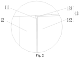
- the indoor air inlet 111 In another implementation manner of the indoor air inlet 111, as shown in Fig. 2 , two mounting convex strips 133 are provided, the two mounting convex strips 133 are disposed on a top and a bottom of the decorative plate main body 132 in one-to-one correspondence, and the mounting convex strips 133 extend along a width direction of the decorative plate main body 132; and the indoor air inlet 111 is enclosed by the two mounting convex strips 133 and an inner wall surface of the decorative plate main body 132.
- two mounting convex strips 133 are provided and respectively disposed on the top and the bottom of the decorative plate main body 132.
- the decorative plate main body 132 is similar to the air conditioner indoor unit in dimensional proportion, i.e., a vertical length is greater than a horizontal width.
- the mounting convex strips 133 extend along the width direction of the decorative plate main body 132.
- the indoor air inlet 111 is enclosed by the upper and lower mounting convex strips 133 and the inner wall surface of the decorative plate main body 132.
- the air conditioner indoor unit includes the refrigerating-heating device 50, and the refrigerating-heating device 50 is located above the fresh air device 20; and an air-conditioner air outlet 112 communicating with an air duct of the refrigerating-heating device 50 is formed in the front panel assembly 11, and the air-conditioner air outlet 112 is located between the decorative plate 13 and the lateral plate assembly 12.
- the air conditioner indoor unit includes the refrigerating-heating device 50, and the fresh air device 20, and the refrigerating-heating device 50 is located above the fresh air device 20.
- the air-conditioner air outlet 112 communicating with the air duct of the refrigerating-heating device 50 is formed in the front panel assembly 11.
- the indoor air inlet 111 is a strip-shaped hole, and the indoor air inlet 111 extends along an extension direction of the front panel assembly 11.
- the indoor air inlet 111 is set into the strip-shaped hole, and a plurality of strip-shaped holes are distributed uniformly, such that indoor dirty air enters the heat exchange core body 40 at a constant speed, and some large object is prevented from being sucked to the heat exchange core body 40 by the indoor air inlet to cause the blockage.
- the heat exchange core body 40 is provided with a fresh air inlet end surface 41 for entering fresh air
- the fresh air device 20 further includes a first filter screen 21, and the first filter screen 21 is disposed on the fresh air inlet end surface 41, such that fresh air entering from the fresh air inlet 311 enters the heat exchange core body 40 after being filtered by the first filter screen 21.
- the first filter screen 21 is disposed on the fresh air inlet end surface 41 of the heat exchange core body 40, such that fresh air entering from the fresh air inlet 311 enters the heat exchange core body 40 after being filtered by the first filter screen 21, the dust and impurity in the indoor fresh air are filtered, and the entry of small animals such as a mouse and an insect is prevented.
- the heat exchange core body 40 is provided with a dirty air inlet end surface 42 for entering dirty air
- the fresh air device 20 further includes a second filter screen 22, and the second filter screen 22 is disposed on the dirty air inlet end surface 42, such that dirty air entering from the dirty air inlet 321 enters the heat exchange core body 40 after being filtered by the second filter screen 22.
- the second filter screen 22 is disposed on the dirty air inlet end surface 42 of the heat exchange core body 40, such that dirty air entering from the dirty air inlet 321 enters the heat exchange core body 40 after being filtered by the second filter screen 22, and the indoor impurity or some large object is prevented from being sucked to the heat exchange core body by the dirty air inlet to cause the blockage of the heat exchange core body and reduce a service life of the heat exchange core body.
- the heat exchange core body 40 is provided with a dirty air outlet end surface 43
- the fresh air device 20 further includes a third filter screen 23, and the third filter screen 23 is disposed on the dirty air outlet end surface 43, such that dirty air flowing through the heat exchange core body 40 enters the dirty air passage 32 after being filtered by the third filter screen 23.
- the third filter screen 23 is disposed on the dirty air outlet end surface 43 of the heat exchange core body 40, such that dirty air flowing through the heat exchange core body 40 enters the dirty air passage 32 after being filtered by the third filter screen 23.
- the present disclosure further provides an air conditioner, including an air conditioner indoor unit and an air conditioner outdoor unit connected with a pipeline of the air conditioner indoor unit; and the air conditioner indoor unit is the above-mentioned air conditioner indoor unit.
- the air conditioner in the present disclosure includes the air conditioner indoor unit and the air conditioner outdoor unit connected with the pipeline of the air conditioner indoor unit, and the air conditioner indoor unit is provided with the fresh air device, such that the exchange between indoor dirty air and outdoor fresh air is implemented; and meanwhile, the heat exchange core body is disposed in the fresh air device, so the problem that the manner of charging fresh air to the room has the large indoor energy wastage in the art known to inventors is solved.
- the upper part is the refrigerating-heating device
- the lower part is the fresh air device.
- the outdoor fresh air outlets are respectively provided under two sides of the air conditioner, and the indoor dirty air inlet is provided at a gap between the decorative plate and the lateral plate assembly of the air conditioner.
- the outdoor fresh air inlet and the indoor dirty air outlet are disposed on a rear lower end of the air conditioner.
- the process that the outdoor fresh air enters the room is as follows.
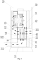
- fresh air passes through the fresh air inlet on the rear lower end of the air conditioner, enters the fresh air passage by the heat exchange core body, and is exhausted from lower portions on two sides of the air conditioner.
- dirty air enters by the indoor dirty air inlet formed in a cabinet internal machine, passes through the filter screen, passes through the heat exchange core body, then enters the dirty air passage formed behind the air exhaust blade, and reaches an outlet on the rear lower end of the air conditioner indoor unit, and thus indoor dirty air is exhausted.
Landscapes
- Engineering & Computer Science (AREA)
- Chemical & Material Sciences (AREA)
- Combustion & Propulsion (AREA)
- Mechanical Engineering (AREA)
- General Engineering & Computer Science (AREA)
- Physics & Mathematics (AREA)
- Thermal Sciences (AREA)
- Air Filters, Heat-Exchange Apparatuses, And Housings Of Air-Conditioning Units (AREA)
Claims (12)
- Innenraumklimaanlageneinheit, umfassend ein Hauptgehäuse (10) und eine Frischluftvorrichtung (20), die in dem Hauptgehäuse (10) angeordnet ist, wobei die Frischluftvorrichtung (20) Folgendes umfasst:ein Frischluftgehäuse (30), einen Frischluftdurchlass (31) und einen Schmutzluftdurchlass (32), die in dem Frischluftgehäuse (30) angeordnet sind, und einen Frischlufteinlass (311) und einen Frischluftauslass (312), die mit dem Frischluftdurchlass (31) in Verbindung stehen, sowie einen Schmutzlufteinlass (321) und einen Schmutzluftauslass (322), die mit dem Schmutzluftdurchlass (32) in Verbindung stehen, die an dem Frischluftgehäuse (30) angeordnet sind; undeinen Wärmetauscherkernkörper (40), wobei der Wärmetauscherkernkörper (40) in dem Frischluftgehäuse (30) angeordnet ist und der Wärmetauscherkernkörper (40) mit dem Frischluftdurchlass (31) und dem Schmutzluftdurchlass (32) derart in Verbindung steht, dass in dem Frischluftdurchlass (31) befindliche Frischluft und in dem Schmutzluftdurchlass (32) befindliche Schmutzluft Wärme in dem Wärmetauscherkernkörper (40) austauschen; unddas Hauptgehäuse (10) eine Frontverkleidungsbaugruppe (11) umfasst, wobei ein Innenraumlufteinlass (111) in der Frontverkleidungsbaugruppe (11) ausgebildet ist und der Innenraumlufteinlass (111) dem Schmutzlufteinlass (321) derart entspricht, dass Innenraumschmutzluft in den Schmutzlufteinlass (321) durch den Innenraumlufteinlass (111) eintritt; und die Frontverkleidungsbaugruppe (11) durch eine Vielzahl von Platten zusammengefügt ist und sich der Innenraumlufteinlass (111) zwischen zwei benachbarten Platten befindet;dadurch gekennzeichnet, dass die Innenraumklimaanlageneinheit vertikal ist, die Vielzahl von Platten eine Seitenplattenbaugruppe (12) und eine Dekorplatte (13) umfasst und der Innenraumlufteinlass (111) zwischen der Dekorplatte (13) und der Seitenplattenbaugruppe (12) bereitgestellt ist.
- Innenraumklimaanlageneinheit nach Anspruch 1, wobei zwei Seitenplattenbaugruppen (12) bereitgestellt sind, die Dekorplatte (13) zwischen den zwei Seitenplattenbaugruppen (12) angeordnet ist und der Innenraumlufteinlass (111) jeweils zwischen der Dekorplatte (13) und den zwei Seitenplattenbaugruppen (12) bereitgestellt ist.
- Innenraumklimaanlageneinheit nach Anspruch 1, wobei die Seitenplattenbaugruppe (12) eine obere Seitenplatte (121) und eine untere Seitenplatte (122) umfasst, wobei die obere Seitenplatte (121) eine Außenseite einer Kühl-/Heizvorrichtung (50) der Innenraumklimaanlageneinheit abdeckt und die untere Seitenplatte (122) eine Außenseite der Frischluftvorrichtung (20) abdeckt; und sich der Innenraumlufteinlass (111) zwischen der unteren Seitenplatte (122) und der Dekorplatte (13) befindet.
- Innenraumklimaanlageneinheit nach Anspruch 1, wobei die Dekorplatte (13) eine einstückig geformte Struktur aufweist und sich die Dekorplatte (13) von einer Oberseite der Innenraumklimaanlageneinheit zu einem Boden der Innenraumklimaanlageneinheit erstreckt.
- Innenraumklimaanlageneinheit nach Anspruch 1, wobei die Dekorplatte (13) einen Dekorplattenhauptkörper (132) und einen konvexen Montagestreifen (133), der auf einer Innenseite des Dekorplattenhauptkörpers (132) angeordnet ist, umfasst und der Dekorplattenhauptkörper (132) mit der Seitenplattenbaugruppe (12) durch den konvexen Montagestreifen (133) in Kontakt steht.
- Innenraumklimaanlageneinheit nach Anspruch 5, wobei sich der konvexe Montagestreifen (133) entlang einer vertikalen Richtung erstreckt, eine Lufteinlassnut in dem konvexen Montagestreifen (133) angeordnet ist und der Innenraumlufteinlass (111) durch eine Fläche der Seitenplattenbaugruppe (12) und eine Innenwandfläche der Lufteinlassnut umschlossen ist.
- Innenraumklimaanlageneinheit nach Anspruch 5, wobei zwei konvexe Montagestreifen (133) bereitgestellt sind, wobei die zwei konvexen Montagestreifen (133) an einer Oberseite und einem Boden des Dekorplattenhauptkörpers (132) in einer Eins-zu-eins-Entsprechung angeordnet sind und sich jeder der konvexen Montagestreifen (133) entlang einer Breitenrichtung des Dekorplattenhauptkörpers (132) erstreckt; und der Innenraumlufteinlass (111) durch die zwei konvexen Montagestreifen (133) und eine Innenwandfläche des Dekorplattenhauptkörpers (132) umschlossen ist.
- Innenraumklimaanlageneinheit nach Anspruch 1, wobei die Innenraumklimaanlageneinheit die Kühl-/Heizvorrichtung (50) umfasst, die Kühl-/Heizvorrichtung (50) einen Luftkanal umfasst und sich die Kühl-/Heizvorrichtung (50) über der Frischluftvorrichtung (20) befindet; und ein Klimaanlagenluftauslass (112), der mit dem Luftkanal in Verbindung steht, in der Frontverkleidungsbaugruppe (11) angeordnet ist und sich der Klimaanlagenluftauslass (112) zwischen der Dekorplatte (13) und der Seitenplattenbaugruppe (12) befindet.
- Innenraumklimaanlageneinheit nach einem der Ansprüche 1 bis 8, wobei der Innenraumlufteinlass (111) aus einem streifenförmigen Loch besteht und sich der Innenraumlufteinlass (111) entlang einer Erstreckungsrichtung der Frontverkleidungsbaugruppe (11) erstreckt.
- Innenraumklimaanlageneinheit nach einem der Ansprüche 1 bis 8, wobei der Wärmetauscherkernkörper (40) mit einer Frischlufteinlassendfläche (41) zum Eintreten von Frischluft versehen ist, wobei die Frischluftvorrichtung (20) ferner eine erste Filterplatte (21) umfasst und die erste Filterplatte (21) an der Frischlufteinlassendfläche (41) derart angeordnet ist, dass von dem Frischlufteinlass (311) eintretende Frischluft in den Wärmetauscherkernkörper (40) eintritt, nachdem sie durch die erste Filterplatte (21) gefiltert wurde.
- Innenraumklimaanlageneinheit nach einem der Ansprüche 1 bis 8, wobei der Wärmetauscherkernkörper (40) mit einer Schmutzlufteinlassendfläche (42) zum Eintreten von Schmutzluft versehen ist, wobei die Frischluftvorrichtung (20) ferner eine zweite Filterplatte (22) umfasst und die zweite Filterplatte (22) an der Schmutzlufteinlassendfläche (42) derart angeordnet ist, dass von dem Schmutzlufteinlass (321) eintretende Schmutzluft in den Wärmetauscherkernkörper (40) eintritt, nachdem sie durch die zweite Filterplatte (22) gefiltert wurde.
- Innenraumklimaanlageneinheit nach einem der Ansprüche 1 bis 8, wobei der Wärmetauscherkernkörper (40) mit einer Schmutzluftauslassendfläche (43) zum Abführen von Schmutzluft versehen ist, wobei die Frischluftvorrichtung (20) ferner eine dritte Filterplatte (23) umfasst und die dritte Filterplatte (23) an der Schmutzluftauslassendfläche (43) derart angeordnet ist, dass durch den Wärmetauscherkernkörper (40) strömende Schmutzluft in den Schmutzluftdurchlass (32) eintritt, nachdem sie durch die dritte Filterplatte (23) gefiltert wurde.
Applications Claiming Priority (2)
| Application Number | Priority Date | Filing Date | Title |
|---|---|---|---|
| CN201810276288 | 2018-03-30 | ||
| PCT/CN2018/125323 WO2019184513A1 (zh) | 2018-03-30 | 2018-12-29 | 空调室内机 |
Publications (3)
| Publication Number | Publication Date |
|---|---|
| EP3779289A1 EP3779289A1 (de) | 2021-02-17 |
| EP3779289A4 EP3779289A4 (de) | 2021-05-26 |
| EP3779289B1 true EP3779289B1 (de) | 2023-09-06 |
Family
ID=68062157
Family Applications (1)
| Application Number | Title | Priority Date | Filing Date |
|---|---|---|---|
| EP18912991.9A Active EP3779289B1 (de) | 2018-03-30 | 2018-12-29 | Innenraumklimaanlageneinheit |
Country Status (3)
| Country | Link |
|---|---|
| EP (1) | EP3779289B1 (de) |
| CN (1) | CN110319491B (de) |
| WO (1) | WO2019184513A1 (de) |
Families Citing this family (4)
| Publication number | Priority date | Publication date | Assignee | Title |
|---|---|---|---|---|
| CN114484596B (zh) * | 2020-11-12 | 2025-08-22 | 广东美的制冷设备有限公司 | 空调室内机和空调器 |
| CN113566356A (zh) * | 2021-08-11 | 2021-10-29 | 珠海格力电器股份有限公司 | 新风装置及空调室内机 |
| CN115638472B (zh) * | 2022-09-30 | 2026-04-21 | 宁波奥克斯电气有限公司 | 新风模块及空调器 |
| CN115654585B (zh) * | 2022-09-30 | 2026-04-21 | 宁波奥克斯电气有限公司 | 空调器 |
Family Cites Families (10)
| Publication number | Priority date | Publication date | Assignee | Title |
|---|---|---|---|---|
| JP2000179889A (ja) * | 1998-12-18 | 2000-06-27 | Fujitsu General Ltd | 一体型空気調和機 |
| CN1590867A (zh) * | 2003-08-25 | 2005-03-09 | 乐金电子(天津)电器有限公司 | 空气调节器 |
| JP4429123B2 (ja) * | 2004-09-10 | 2010-03-10 | 三洋電機株式会社 | 空気調和機 |
| JP4794280B2 (ja) * | 2005-11-14 | 2011-10-19 | 三洋電機株式会社 | 空気調和機 |
| WO2010083643A1 (zh) * | 2009-01-21 | 2010-07-29 | Zeng Guohui | 节能换气装置 |
| CN201589390U (zh) * | 2009-11-06 | 2010-09-22 | 海尔集团公司 | 导风板 |
| CN102777984A (zh) * | 2011-05-11 | 2012-11-14 | 吴勇 | 一种毛细管网空调房间用换风、除湿机 |
| CN202734058U (zh) * | 2012-06-25 | 2013-02-13 | 广东美的制冷设备有限公司 | 带新风热回收的空调器室内机 |
| CN205825324U (zh) * | 2016-03-25 | 2016-12-21 | 成都易态易优健康科技有限公司 | 一种新风装置 |
| CN209213993U (zh) * | 2018-03-30 | 2019-08-06 | 珠海格力电器股份有限公司 | 空调室内机 |
-
2018
- 2018-12-10 CN CN201811506429.2A patent/CN110319491B/zh active Active
- 2018-12-29 WO PCT/CN2018/125323 patent/WO2019184513A1/zh not_active Ceased
- 2018-12-29 EP EP18912991.9A patent/EP3779289B1/de active Active
Also Published As
| Publication number | Publication date |
|---|---|
| EP3779289A4 (de) | 2021-05-26 |
| CN110319491B (zh) | 2024-09-03 |
| WO2019184513A1 (zh) | 2019-10-03 |
| CN110319491A (zh) | 2019-10-11 |
| EP3779289A1 (de) | 2021-02-17 |
Similar Documents
| Publication | Publication Date | Title |
|---|---|---|
| EP3779289A1 (de) | Innenraumklimaanlageneinheit | |
| KR20060093742A (ko) | 초박형 환기장치 | |
| CN105890100A (zh) | 窗式空气净化换热器 | |
| CN110319489B (zh) | 空调室内机 | |
| EP3779288B1 (de) | Innenraumeinheit einer klimaanlage | |
| CN212299314U (zh) | 新风机 | |
| CN102478303A (zh) | 空调室内空气过滤网结构 | |
| ES1309686U (es) | Unidad descentralizada de admision y escape con recuperacion de calor | |
| CN110319501B (zh) | 空调室内机 | |
| CN211901072U (zh) | 一种风机及设有该风机的风幕机 | |
| CN110319495B (zh) | 空调室内机 | |
| CN205909459U (zh) | 空调化霜罩及室外机化霜装置 | |
| CN210460397U (zh) | 一种生态窗 | |
| EP3779287B1 (de) | Klimaanlageninnenraumeinheit und klimaanlage damit | |
| CN208750939U (zh) | 新风装置和空调室内机 | |
| CN209213993U (zh) | 空调室内机 | |
| CN209068671U (zh) | 多面摆放立式新风机 | |
| CN210379966U (zh) | 一种电气柜的除尘散热结构 | |
| CN102478300B (zh) | 分体式空调室内机的正面框架结构 | |
| CN211854211U (zh) | 新风模块及空调器 | |
| CN213453893U (zh) | 新风装置和空调器 | |
| CN108679768B (zh) | 一种新风系统的室内机 | |
| CN219328149U (zh) | 一种水帘装置 | |
| CN110578967B (zh) | 空调室内机 | |
| CN114754446A (zh) | 一种双风道导热回收新风保温一体窗及建筑 |
Legal Events
| Date | Code | Title | Description |
|---|---|---|---|
| STAA | Information on the status of an ep patent application or granted ep patent |
Free format text: STATUS: THE INTERNATIONAL PUBLICATION HAS BEEN MADE |
|
| PUAI | Public reference made under article 153(3) epc to a published international application that has entered the european phase |
Free format text: ORIGINAL CODE: 0009012 |
|
| STAA | Information on the status of an ep patent application or granted ep patent |
Free format text: STATUS: REQUEST FOR EXAMINATION WAS MADE |
|
| 17P | Request for examination filed |
Effective date: 20200814 |
|
| AK | Designated contracting states |
Kind code of ref document: A1 Designated state(s): AL AT BE BG CH CY CZ DE DK EE ES FI FR GB GR HR HU IE IS IT LI LT LU LV MC MK MT NL NO PL PT RO RS SE SI SK SM TR |
|
| AX | Request for extension of the european patent |
Extension state: BA ME |
|
| A4 | Supplementary search report drawn up and despatched |
Effective date: 20210428 |
|
| RIC1 | Information provided on ipc code assigned before grant |
Ipc: F24F 1/00 20190101AFI20210421BHEP Ipc: F24F 13/20 20060101ALI20210421BHEP Ipc: F24F 1/0007 20190101ALI20210421BHEP Ipc: F24F 1/0063 20190101ALI20210421BHEP Ipc: F24F 13/30 20060101ALI20210421BHEP Ipc: F24F 1/0035 20190101ALI20210421BHEP Ipc: F24F 1/0038 20190101ALI20210421BHEP Ipc: F24F 1/005 20190101ALI20210421BHEP Ipc: F24F 12/00 20060101ALI20210421BHEP |
|
| DAV | Request for validation of the european patent (deleted) | ||
| DAX | Request for extension of the european patent (deleted) | ||
| GRAP | Despatch of communication of intention to grant a patent |
Free format text: ORIGINAL CODE: EPIDOSNIGR1 |
|
| STAA | Information on the status of an ep patent application or granted ep patent |
Free format text: STATUS: GRANT OF PATENT IS INTENDED |
|
| P01 | Opt-out of the competence of the unified patent court (upc) registered |
Effective date: 20230530 |
|
| INTG | Intention to grant announced |
Effective date: 20230620 |
|
| GRAS | Grant fee paid |
Free format text: ORIGINAL CODE: EPIDOSNIGR3 |
|
| GRAA | (expected) grant |
Free format text: ORIGINAL CODE: 0009210 |
|
| STAA | Information on the status of an ep patent application or granted ep patent |
Free format text: STATUS: THE PATENT HAS BEEN GRANTED |
|
| AK | Designated contracting states |
Kind code of ref document: B1 Designated state(s): AL AT BE BG CH CY CZ DE DK EE ES FI FR GB GR HR HU IE IS IT LI LT LU LV MC MK MT NL NO PL PT RO RS SE SI SK SM TR |
|
| REG | Reference to a national code |
Ref country code: GB Ref legal event code: FG4D |
|
| REG | Reference to a national code |
Ref country code: CH Ref legal event code: EP |
|
| REG | Reference to a national code |
Ref country code: IE Ref legal event code: FG4D |
|
| REG | Reference to a national code |
Ref country code: DE Ref legal event code: R096 Ref document number: 602018057287 Country of ref document: DE |
|
| REG | Reference to a national code |
Ref country code: LT Ref legal event code: MG9D |
|
| REG | Reference to a national code |
Ref country code: NL Ref legal event code: MP Effective date: 20230906 |
|
| PG25 | Lapsed in a contracting state [announced via postgrant information from national office to epo] |
Ref country code: GR Free format text: LAPSE BECAUSE OF FAILURE TO SUBMIT A TRANSLATION OF THE DESCRIPTION OR TO PAY THE FEE WITHIN THE PRESCRIBED TIME-LIMIT Effective date: 20231207 |
|
| PG25 | Lapsed in a contracting state [announced via postgrant information from national office to epo] |
Ref country code: SE Free format text: LAPSE BECAUSE OF FAILURE TO SUBMIT A TRANSLATION OF THE DESCRIPTION OR TO PAY THE FEE WITHIN THE PRESCRIBED TIME-LIMIT Effective date: 20230906 Ref country code: RS Free format text: LAPSE BECAUSE OF FAILURE TO SUBMIT A TRANSLATION OF THE DESCRIPTION OR TO PAY THE FEE WITHIN THE PRESCRIBED TIME-LIMIT Effective date: 20230906 Ref country code: NO Free format text: LAPSE BECAUSE OF FAILURE TO SUBMIT A TRANSLATION OF THE DESCRIPTION OR TO PAY THE FEE WITHIN THE PRESCRIBED TIME-LIMIT Effective date: 20231206 Ref country code: LV Free format text: LAPSE BECAUSE OF FAILURE TO SUBMIT A TRANSLATION OF THE DESCRIPTION OR TO PAY THE FEE WITHIN THE PRESCRIBED TIME-LIMIT Effective date: 20230906 Ref country code: LT Free format text: LAPSE BECAUSE OF FAILURE TO SUBMIT A TRANSLATION OF THE DESCRIPTION OR TO PAY THE FEE WITHIN THE PRESCRIBED TIME-LIMIT Effective date: 20230906 Ref country code: HR Free format text: LAPSE BECAUSE OF FAILURE TO SUBMIT A TRANSLATION OF THE DESCRIPTION OR TO PAY THE FEE WITHIN THE PRESCRIBED TIME-LIMIT Effective date: 20230906 Ref country code: GR Free format text: LAPSE BECAUSE OF FAILURE TO SUBMIT A TRANSLATION OF THE DESCRIPTION OR TO PAY THE FEE WITHIN THE PRESCRIBED TIME-LIMIT Effective date: 20231207 Ref country code: FI Free format text: LAPSE BECAUSE OF FAILURE TO SUBMIT A TRANSLATION OF THE DESCRIPTION OR TO PAY THE FEE WITHIN THE PRESCRIBED TIME-LIMIT Effective date: 20230906 |
|
| REG | Reference to a national code |
Ref country code: AT Ref legal event code: MK05 Ref document number: 1609004 Country of ref document: AT Kind code of ref document: T Effective date: 20230906 |
|
| PG25 | Lapsed in a contracting state [announced via postgrant information from national office to epo] |
Ref country code: NL Free format text: LAPSE BECAUSE OF FAILURE TO SUBMIT A TRANSLATION OF THE DESCRIPTION OR TO PAY THE FEE WITHIN THE PRESCRIBED TIME-LIMIT Effective date: 20230906 |
|
| PG25 | Lapsed in a contracting state [announced via postgrant information from national office to epo] |
Ref country code: IS Free format text: LAPSE BECAUSE OF FAILURE TO SUBMIT A TRANSLATION OF THE DESCRIPTION OR TO PAY THE FEE WITHIN THE PRESCRIBED TIME-LIMIT Effective date: 20240106 |
|
| PG25 | Lapsed in a contracting state [announced via postgrant information from national office to epo] |
Ref country code: AT Free format text: LAPSE BECAUSE OF FAILURE TO SUBMIT A TRANSLATION OF THE DESCRIPTION OR TO PAY THE FEE WITHIN THE PRESCRIBED TIME-LIMIT Effective date: 20230906 |
|
| PG25 | Lapsed in a contracting state [announced via postgrant information from national office to epo] |
Ref country code: ES Free format text: LAPSE BECAUSE OF FAILURE TO SUBMIT A TRANSLATION OF THE DESCRIPTION OR TO PAY THE FEE WITHIN THE PRESCRIBED TIME-LIMIT Effective date: 20230906 |
|
| PG25 | Lapsed in a contracting state [announced via postgrant information from national office to epo] |
Ref country code: SM Free format text: LAPSE BECAUSE OF FAILURE TO SUBMIT A TRANSLATION OF THE DESCRIPTION OR TO PAY THE FEE WITHIN THE PRESCRIBED TIME-LIMIT Effective date: 20230906 Ref country code: RO Free format text: LAPSE BECAUSE OF FAILURE TO SUBMIT A TRANSLATION OF THE DESCRIPTION OR TO PAY THE FEE WITHIN THE PRESCRIBED TIME-LIMIT Effective date: 20230906 Ref country code: IS Free format text: LAPSE BECAUSE OF FAILURE TO SUBMIT A TRANSLATION OF THE DESCRIPTION OR TO PAY THE FEE WITHIN THE PRESCRIBED TIME-LIMIT Effective date: 20240106 Ref country code: ES Free format text: LAPSE BECAUSE OF FAILURE TO SUBMIT A TRANSLATION OF THE DESCRIPTION OR TO PAY THE FEE WITHIN THE PRESCRIBED TIME-LIMIT Effective date: 20230906 Ref country code: EE Free format text: LAPSE BECAUSE OF FAILURE TO SUBMIT A TRANSLATION OF THE DESCRIPTION OR TO PAY THE FEE WITHIN THE PRESCRIBED TIME-LIMIT Effective date: 20230906 Ref country code: CZ Free format text: LAPSE BECAUSE OF FAILURE TO SUBMIT A TRANSLATION OF THE DESCRIPTION OR TO PAY THE FEE WITHIN THE PRESCRIBED TIME-LIMIT Effective date: 20230906 Ref country code: AT Free format text: LAPSE BECAUSE OF FAILURE TO SUBMIT A TRANSLATION OF THE DESCRIPTION OR TO PAY THE FEE WITHIN THE PRESCRIBED TIME-LIMIT Effective date: 20230906 Ref country code: SK Free format text: LAPSE BECAUSE OF FAILURE TO SUBMIT A TRANSLATION OF THE DESCRIPTION OR TO PAY THE FEE WITHIN THE PRESCRIBED TIME-LIMIT Effective date: 20230906 Ref country code: PT Free format text: LAPSE BECAUSE OF FAILURE TO SUBMIT A TRANSLATION OF THE DESCRIPTION OR TO PAY THE FEE WITHIN THE PRESCRIBED TIME-LIMIT Effective date: 20240108 |
|
| PG25 | Lapsed in a contracting state [announced via postgrant information from national office to epo] |
Ref country code: PL Free format text: LAPSE BECAUSE OF FAILURE TO SUBMIT A TRANSLATION OF THE DESCRIPTION OR TO PAY THE FEE WITHIN THE PRESCRIBED TIME-LIMIT Effective date: 20230906 Ref country code: IT Free format text: LAPSE BECAUSE OF FAILURE TO SUBMIT A TRANSLATION OF THE DESCRIPTION OR TO PAY THE FEE WITHIN THE PRESCRIBED TIME-LIMIT Effective date: 20230906 |
|
| REG | Reference to a national code |
Ref country code: DE Ref legal event code: R097 Ref document number: 602018057287 Country of ref document: DE |
|
| PG25 | Lapsed in a contracting state [announced via postgrant information from national office to epo] |
Ref country code: DK Free format text: LAPSE BECAUSE OF FAILURE TO SUBMIT A TRANSLATION OF THE DESCRIPTION OR TO PAY THE FEE WITHIN THE PRESCRIBED TIME-LIMIT Effective date: 20230906 |
|
| PLBE | No opposition filed within time limit |
Free format text: ORIGINAL CODE: 0009261 |
|
| STAA | Information on the status of an ep patent application or granted ep patent |
Free format text: STATUS: NO OPPOSITION FILED WITHIN TIME LIMIT |
|
| PG25 | Lapsed in a contracting state [announced via postgrant information from national office to epo] |
Ref country code: DK Free format text: LAPSE BECAUSE OF FAILURE TO SUBMIT A TRANSLATION OF THE DESCRIPTION OR TO PAY THE FEE WITHIN THE PRESCRIBED TIME-LIMIT Effective date: 20230906 Ref country code: SI Free format text: LAPSE BECAUSE OF FAILURE TO SUBMIT A TRANSLATION OF THE DESCRIPTION OR TO PAY THE FEE WITHIN THE PRESCRIBED TIME-LIMIT Effective date: 20230906 |
|
| REG | Reference to a national code |
Ref country code: CH Ref legal event code: PL |
|
| 26N | No opposition filed |
Effective date: 20240607 |
|
| PG25 | Lapsed in a contracting state [announced via postgrant information from national office to epo] |
Ref country code: LU Free format text: LAPSE BECAUSE OF NON-PAYMENT OF DUE FEES Effective date: 20231229 |
|
| PG25 | Lapsed in a contracting state [announced via postgrant information from national office to epo] |
Ref country code: MC Free format text: LAPSE BECAUSE OF FAILURE TO SUBMIT A TRANSLATION OF THE DESCRIPTION OR TO PAY THE FEE WITHIN THE PRESCRIBED TIME-LIMIT Effective date: 20230906 |
|
| GBPC | Gb: european patent ceased through non-payment of renewal fee |
Effective date: 20231229 |
|
| REG | Reference to a national code |
Ref country code: BE Ref legal event code: MM Effective date: 20231231 |
|
| PG25 | Lapsed in a contracting state [announced via postgrant information from national office to epo] |
Ref country code: MC Free format text: LAPSE BECAUSE OF FAILURE TO SUBMIT A TRANSLATION OF THE DESCRIPTION OR TO PAY THE FEE WITHIN THE PRESCRIBED TIME-LIMIT Effective date: 20230906 Ref country code: LU Free format text: LAPSE BECAUSE OF NON-PAYMENT OF DUE FEES Effective date: 20231229 |
|
| REG | Reference to a national code |
Ref country code: IE Ref legal event code: MM4A |
|
| PG25 | Lapsed in a contracting state [announced via postgrant information from national office to epo] |
Ref country code: IE Free format text: LAPSE BECAUSE OF NON-PAYMENT OF DUE FEES Effective date: 20231229 |
|
| PG25 | Lapsed in a contracting state [announced via postgrant information from national office to epo] |
Ref country code: GB Free format text: LAPSE BECAUSE OF NON-PAYMENT OF DUE FEES Effective date: 20231229 |
|
| PG25 | Lapsed in a contracting state [announced via postgrant information from national office to epo] |
Ref country code: BE Free format text: LAPSE BECAUSE OF NON-PAYMENT OF DUE FEES Effective date: 20231231 |
|
| PG25 | Lapsed in a contracting state [announced via postgrant information from national office to epo] |
Ref country code: FR Free format text: LAPSE BECAUSE OF NON-PAYMENT OF DUE FEES Effective date: 20231231 |
|
| PG25 | Lapsed in a contracting state [announced via postgrant information from national office to epo] |
Ref country code: CH Free format text: LAPSE BECAUSE OF NON-PAYMENT OF DUE FEES Effective date: 20231231 |
|
| PG25 | Lapsed in a contracting state [announced via postgrant information from national office to epo] |
Ref country code: IE Free format text: LAPSE BECAUSE OF NON-PAYMENT OF DUE FEES Effective date: 20231229 Ref country code: GB Free format text: LAPSE BECAUSE OF NON-PAYMENT OF DUE FEES Effective date: 20231229 Ref country code: FR Free format text: LAPSE BECAUSE OF NON-PAYMENT OF DUE FEES Effective date: 20231231 Ref country code: CH Free format text: LAPSE BECAUSE OF NON-PAYMENT OF DUE FEES Effective date: 20231231 Ref country code: BE Free format text: LAPSE BECAUSE OF NON-PAYMENT OF DUE FEES Effective date: 20231231 |
|
| PG25 | Lapsed in a contracting state [announced via postgrant information from national office to epo] |
Ref country code: BG Free format text: LAPSE BECAUSE OF FAILURE TO SUBMIT A TRANSLATION OF THE DESCRIPTION OR TO PAY THE FEE WITHIN THE PRESCRIBED TIME-LIMIT Effective date: 20230906 |
|
| PG25 | Lapsed in a contracting state [announced via postgrant information from national office to epo] |
Ref country code: BG Free format text: LAPSE BECAUSE OF FAILURE TO SUBMIT A TRANSLATION OF THE DESCRIPTION OR TO PAY THE FEE WITHIN THE PRESCRIBED TIME-LIMIT Effective date: 20230906 |
|
| PG25 | Lapsed in a contracting state [announced via postgrant information from national office to epo] |
Ref country code: CY Free format text: LAPSE BECAUSE OF FAILURE TO SUBMIT A TRANSLATION OF THE DESCRIPTION OR TO PAY THE FEE WITHIN THE PRESCRIBED TIME-LIMIT; INVALID AB INITIO Effective date: 20181229 |
|
| PG25 | Lapsed in a contracting state [announced via postgrant information from national office to epo] |
Ref country code: HU Free format text: LAPSE BECAUSE OF FAILURE TO SUBMIT A TRANSLATION OF THE DESCRIPTION OR TO PAY THE FEE WITHIN THE PRESCRIBED TIME-LIMIT; INVALID AB INITIO Effective date: 20181229 |
|
| PG25 | Lapsed in a contracting state [announced via postgrant information from national office to epo] |
Ref country code: TR Free format text: LAPSE BECAUSE OF FAILURE TO SUBMIT A TRANSLATION OF THE DESCRIPTION OR TO PAY THE FEE WITHIN THE PRESCRIBED TIME-LIMIT Effective date: 20230906 |
|
| PGFP | Annual fee paid to national office [announced via postgrant information from national office to epo] |
Ref country code: DE Payment date: 20251222 Year of fee payment: 8 |