EP3779243B1 - Shift driving device - Google Patents
Shift driving device Download PDFInfo
- Publication number
- EP3779243B1 EP3779243B1 EP19777417.7A EP19777417A EP3779243B1 EP 3779243 B1 EP3779243 B1 EP 3779243B1 EP 19777417 A EP19777417 A EP 19777417A EP 3779243 B1 EP3779243 B1 EP 3779243B1
- Authority
- EP
- European Patent Office
- Prior art keywords
- rack
- take
- gear
- straight rail
- rail section
- Prior art date
- Legal status (The legal status is an assumption and is not a legal conclusion. Google has not performed a legal analysis and makes no representation as to the accuracy of the status listed.)
- Active
Links
Images



Classifications
-
- F—MECHANICAL ENGINEERING; LIGHTING; HEATING; WEAPONS; BLASTING
- F16—ENGINEERING ELEMENTS AND UNITS; GENERAL MEASURES FOR PRODUCING AND MAINTAINING EFFECTIVE FUNCTIONING OF MACHINES OR INSTALLATIONS; THERMAL INSULATION IN GENERAL
- F16H—GEARING
- F16H63/00—Control outputs from the control unit to change-speed- or reversing-gearings for conveying rotary motion or to other devices than the final output mechanism
- F16H63/02—Final output mechanisms therefor; Actuating means for the final output mechanisms
- F16H63/30—Constructional features of the final output mechanisms
- F16H63/304—Constructional features of the final output mechanisms the final output mechanisms comprising elements moved by electrical or magnetic force
-
- F—MECHANICAL ENGINEERING; LIGHTING; HEATING; WEAPONS; BLASTING
- F16—ENGINEERING ELEMENTS AND UNITS; GENERAL MEASURES FOR PRODUCING AND MAINTAINING EFFECTIVE FUNCTIONING OF MACHINES OR INSTALLATIONS; THERMAL INSULATION IN GENERAL
- F16H—GEARING
- F16H61/00—Control functions within control units of change-speed- or reversing-gearings for conveying rotary motion ; Control of exclusively fluid gearing, friction gearing, gearings with endless flexible members or other particular types of gearing
- F16H61/26—Generation or transmission of movements for final actuating mechanisms
- F16H61/28—Generation or transmission of movements for final actuating mechanisms with at least one movement of the final actuating mechanism being caused by a non-mechanical force, e.g. power-assisted
- F16H61/32—Electric motors , actuators or related electrical control means therefor
-
- F—MECHANICAL ENGINEERING; LIGHTING; HEATING; WEAPONS; BLASTING
- F16—ENGINEERING ELEMENTS AND UNITS; GENERAL MEASURES FOR PRODUCING AND MAINTAINING EFFECTIVE FUNCTIONING OF MACHINES OR INSTALLATIONS; THERMAL INSULATION IN GENERAL
- F16H—GEARING
- F16H19/00—Gearings comprising essentially only toothed gears or friction members and not capable of conveying indefinitely-continuing rotary motion
- F16H19/02—Gearings comprising essentially only toothed gears or friction members and not capable of conveying indefinitely-continuing rotary motion for interconverting rotary or oscillating motion and reciprocating motion
- F16H19/04—Gearings comprising essentially only toothed gears or friction members and not capable of conveying indefinitely-continuing rotary motion for interconverting rotary or oscillating motion and reciprocating motion comprising a rack
-
- F—MECHANICAL ENGINEERING; LIGHTING; HEATING; WEAPONS; BLASTING
- F16—ENGINEERING ELEMENTS AND UNITS; GENERAL MEASURES FOR PRODUCING AND MAINTAINING EFFECTIVE FUNCTIONING OF MACHINES OR INSTALLATIONS; THERMAL INSULATION IN GENERAL
- F16H—GEARING
- F16H19/00—Gearings comprising essentially only toothed gears or friction members and not capable of conveying indefinitely-continuing rotary motion
- F16H19/02—Gearings comprising essentially only toothed gears or friction members and not capable of conveying indefinitely-continuing rotary motion for interconverting rotary or oscillating motion and reciprocating motion
- F16H19/06—Gearings comprising essentially only toothed gears or friction members and not capable of conveying indefinitely-continuing rotary motion for interconverting rotary or oscillating motion and reciprocating motion comprising flexible members, e.g. an endless flexible member
-
- F—MECHANICAL ENGINEERING; LIGHTING; HEATING; WEAPONS; BLASTING
- F16—ENGINEERING ELEMENTS AND UNITS; GENERAL MEASURES FOR PRODUCING AND MAINTAINING EFFECTIVE FUNCTIONING OF MACHINES OR INSTALLATIONS; THERMAL INSULATION IN GENERAL
- F16H—GEARING
- F16H55/00—Elements with teeth or friction surfaces for conveying motion; Worms, pulleys or sheaves for gearing mechanisms
- F16H55/02—Toothed members; Worms
- F16H55/26—Racks
-
- F—MECHANICAL ENGINEERING; LIGHTING; HEATING; WEAPONS; BLASTING
- F16—ENGINEERING ELEMENTS AND UNITS; GENERAL MEASURES FOR PRODUCING AND MAINTAINING EFFECTIVE FUNCTIONING OF MACHINES OR INSTALLATIONS; THERMAL INSULATION IN GENERAL
- F16H—GEARING
- F16H57/00—General details of gearing
- F16H57/02—Gearboxes; Mounting gearing therein
-
- F—MECHANICAL ENGINEERING; LIGHTING; HEATING; WEAPONS; BLASTING
- F16—ENGINEERING ELEMENTS AND UNITS; GENERAL MEASURES FOR PRODUCING AND MAINTAINING EFFECTIVE FUNCTIONING OF MACHINES OR INSTALLATIONS; THERMAL INSULATION IN GENERAL
- F16H—GEARING
- F16H63/00—Control outputs from the control unit to change-speed- or reversing-gearings for conveying rotary motion or to other devices than the final output mechanism
- F16H63/02—Final output mechanisms therefor; Actuating means for the final output mechanisms
- F16H63/30—Constructional features of the final output mechanisms
-
- F—MECHANICAL ENGINEERING; LIGHTING; HEATING; WEAPONS; BLASTING
- F16—ENGINEERING ELEMENTS AND UNITS; GENERAL MEASURES FOR PRODUCING AND MAINTAINING EFFECTIVE FUNCTIONING OF MACHINES OR INSTALLATIONS; THERMAL INSULATION IN GENERAL
- F16H—GEARING
- F16H57/00—General details of gearing
- F16H57/02—Gearboxes; Mounting gearing therein
- F16H2057/02039—Gearboxes for particular applications
- F16H2057/02082—Gearboxes for particular applications for application in vehicles other than propelling, e.g. adjustment of parts
-
- F—MECHANICAL ENGINEERING; LIGHTING; HEATING; WEAPONS; BLASTING
- F16—ENGINEERING ELEMENTS AND UNITS; GENERAL MEASURES FOR PRODUCING AND MAINTAINING EFFECTIVE FUNCTIONING OF MACHINES OR INSTALLATIONS; THERMAL INSULATION IN GENERAL
- F16H—GEARING
- F16H61/00—Control functions within control units of change-speed- or reversing-gearings for conveying rotary motion ; Control of exclusively fluid gearing, friction gearing, gearings with endless flexible members or other particular types of gearing
- F16H61/26—Generation or transmission of movements for final actuating mechanisms
- F16H61/28—Generation or transmission of movements for final actuating mechanisms with at least one movement of the final actuating mechanism being caused by a non-mechanical force, e.g. power-assisted
- F16H2061/2876—Racks
-
- F—MECHANICAL ENGINEERING; LIGHTING; HEATING; WEAPONS; BLASTING
- F16—ENGINEERING ELEMENTS AND UNITS; GENERAL MEASURES FOR PRODUCING AND MAINTAINING EFFECTIVE FUNCTIONING OF MACHINES OR INSTALLATIONS; THERMAL INSULATION IN GENERAL
- F16H—GEARING
- F16H61/00—Control functions within control units of change-speed- or reversing-gearings for conveying rotary motion ; Control of exclusively fluid gearing, friction gearing, gearings with endless flexible members or other particular types of gearing
- F16H61/26—Generation or transmission of movements for final actuating mechanisms
- F16H61/28—Generation or transmission of movements for final actuating mechanisms with at least one movement of the final actuating mechanism being caused by a non-mechanical force, e.g. power-assisted
- F16H2061/2884—Screw-nut devices
-
- F—MECHANICAL ENGINEERING; LIGHTING; HEATING; WEAPONS; BLASTING
- F16—ENGINEERING ELEMENTS AND UNITS; GENERAL MEASURES FOR PRODUCING AND MAINTAINING EFFECTIVE FUNCTIONING OF MACHINES OR INSTALLATIONS; THERMAL INSULATION IN GENERAL
- F16H—GEARING
- F16H63/00—Control outputs from the control unit to change-speed- or reversing-gearings for conveying rotary motion or to other devices than the final output mechanism
- F16H63/02—Final output mechanisms therefor; Actuating means for the final output mechanisms
- F16H63/30—Constructional features of the final output mechanisms
- F16H63/304—Constructional features of the final output mechanisms the final output mechanisms comprising elements moved by electrical or magnetic force
- F16H2063/3059—Constructional features of the final output mechanisms the final output mechanisms comprising elements moved by electrical or magnetic force using racks
-
- F—MECHANICAL ENGINEERING; LIGHTING; HEATING; WEAPONS; BLASTING
- F16—ENGINEERING ELEMENTS AND UNITS; GENERAL MEASURES FOR PRODUCING AND MAINTAINING EFFECTIVE FUNCTIONING OF MACHINES OR INSTALLATIONS; THERMAL INSULATION IN GENERAL
- F16H—GEARING
- F16H63/00—Control outputs from the control unit to change-speed- or reversing-gearings for conveying rotary motion or to other devices than the final output mechanism
- F16H63/02—Final output mechanisms therefor; Actuating means for the final output mechanisms
- F16H63/30—Constructional features of the final output mechanisms
- F16H63/304—Constructional features of the final output mechanisms the final output mechanisms comprising elements moved by electrical or magnetic force
- F16H2063/3063—Constructional features of the final output mechanisms the final output mechanisms comprising elements moved by electrical or magnetic force using screw devices
Definitions
- the present invention relates to the technical field of gearbox shifting, and in particular to a shift drive.
- an electronic gearbox adapted to an electronic shift driver (SBW, Shift By Wire) is capable of receiving a shift signal transmitted from the SBW, thereby performing a shift operation.
- the publication No. CN205136570U Electronic Shift Driver for Automobiles
- a motor drives a driving wheel to rotate, and the driving wheel drives a screw to rotate via a belt and a driven wheel, so that a slider set on the screw moves axially.
- a bulge disposed on the slider can push against a rack to move it in a track, and then turn a magnetic gear to rotate. Rotation of the magnetic gear will produce a magnetic field change, so that a Hall sensor senses the magnetic field change to realize the gear identification information.
- the TCU adjusts the motor speed according to the gear identification information, and moves a push rod connected to the slider to a designated position, thereby completing the shift.
- the electronic shift driver including the above-described known embodiment provided by the present applicant can provide the electronic gearbox with the driving external force for performing the handover to the P gear, but cannot provide the external force for performing handover to R, N, and D gears.
- this type of electronic shift driver is applicable only to electronic gearboxes capable of receiving R-gear, N-gear, and D-gear signals, and cannot be expanded to automatic gearboxes of which other technologies are already mature. This limits the popularity of the electronic shift driver and makes it being not applicable to automatic gearboxes that are intended to maintain the existing configuration without technical reconstruction, but are intended to achieve the same shifting function as electronic shifters.
- WO2017170306 discloses a linear extension/retraction mechanism having a plurality of first and second pieces coupled together in a bendable manner, rollers joining join the first and second pieces together such that a pillar-like body is formed and supported such that it is movable forward and backward.
- a drive gear is provided for moving the first and second pieces forward and backward; and a motor unit for rotating the drive gear.
- Each of the first pieces includes, on a surface at a side to be joined to the corresponding second piece, a linear gear engaged with the drive gear, and includes a projection portion projected toward the second piece side.
- At least one third piece is connected to the rearmost first piece among the plurality of first pieces, in a bendable manner.
- a current collector system for a vehicle is vehicle that can be moved in a longitudinal direction along a power rail arrangement.
- the current collector system includes at least one current collector trolley, one or more current collector contacts arranged on the at least one current collector trolley and configured to be connected to power rails of the power rail arrangement, a telescopic arm configured to be fixed to the vehicle, and an adjustment drive comprising at least one rigid chain arrangement and at least a first rigid chain drive configured to extend and/or retract the telescopic arm.
- the telescopic arm comprises at least one telescopable telescopic stage, wherein an end of the rigid chain arrangement is connected to a most extendible telescopic stage of the at least one telescopable telescopic stage or to the current collector trolley in a fixed manner or is configured to be connected by means of a locking mechanism.
- An electronic shift driver as described in the above known embodiment which is only suitable for providing a gearbox with an external force for performing handover to the P gear, has a short stroke (generally about 17 mm) for its protrusion.
- the stroke of the protrusion will be greatly extended if it is intended to provide an automatic gearbox having existing known construction with an external force for performing handover to all gears including P, R, N and D gears.
- embodiments of the present invention provide a shift drive which can be applicable to an automatic gearbox of the existing known construction, such that the shift drive can achieve the same shifting function as an electronic shifter without technical retrofitting.
- the present invention provides the following technical solution.
- a shift drive comprising:
- the gear housing is provided thereon with a gear cover adapted thereto, and the gear cover is provided thereon with an elongated opening of which the connecting member extends out.
- the gear housing is provided with the take-up release section on at least one side of the straight rail section.
- the straight rail section may be located below the induction gear, and the take-up release section is disposed at at least one end of the straight rail section.
- both ends of the straight rail section are bent upward and downward, respectively, to form two take-up release sections which are located in the same plane as the straight rail section.
- connection portion is provided thereon with a rigid holding portion
- the connecting member is a protrusion extending from the rigid holding portion toward the actuating mechanism and inserted into a connecting hole provided in the actuating mechanism.
- the length of the straight rail section is set such that the connection portion can only slide freely therein along with the actuating mechanism.
- the rack is provided with a plurality of longitudinally spaced notches at least on a side wall near the end portion of the rack that is capable of a recoverable deformation, so that the end portion of the rack that is capable of a recoverable deformation is bent in a drag-reducing manner to enter the take-up release section.
- the driving mechanism comprises a motor
- the gear housing is provided with a magnetic field sensing element at a position corresponding to the induction gear
- the magnetic field sensing element and the motor are in signal connection to a central control unit of an automobile.
- the shift drive of the embodiment of the present invention by providing in the gear housing a take-up release section having a length projected on the extension line in the length direction of the straight rail section that is less than the length of the track thereof, the end portion of the rack being received in the track slot, that is capable of a recoverable deformation, can slide in or out of the take-up release section, so as to greatly extend the stroke of the rack under the premise of occupying the same space, so as to meet the requirement that the shift drive is applicable to the automatic gearbox which requires the rack has a long stroke.
- the shift drive according to the embodiment of the present invention can be applied to an automatic gearbox of an existing known construction without technical retrofitting, and can achieve the same shifting function as an electronic shifter.
- the shift drive according to the embodiment of the present invention has better versatility and it is easy to realize the modularization of the product.
- the embodiment of the present invention provides a shift drive which may comprise: an actuating mechanism 6 capable of being driven by a driving mechanism 1, the actuating mechanism 6 being for connection to a gearbox (not shown); a rack 3 linked with the actuating mechanism 6, at least one end of the rack 3 being capable of a recoverable deformation, the rack 3 including a connection portion, the connection portion being connected to the actuating mechanism 6 through a connecting member 301; a gear housing 5() provided with an induction gear 4 that meshes with the rack 3, the gear housing 5 having a track slot 501 that receives the rack 3 therein, the track slot 501 having a take-up release section 501a and a straight rail section 501b, wherein an end portion of the rack 3 that is capable of a recoverable deformation can slide in or out of the take-up release section 501a, and the length of projection (the downward projection as shown in FIG. 3 ) of the take-up release section 501a on an extension line in the direction
- the shift drive of the embodiment of the present invention by providing in the gear housing 5 a take-up release section 501a having a length projected on the extension line in the length direction of the straight rail section 501b that is less than the length of the track thereof, the end portion of the rack 3 being received in the track slot 501, that is capable of a recoverable deformation, can slide in or out of the take-up release section 501a, so as to greatly extend the stroke of the rack 3 under the premise of occupying the same space, so as to meet the requirement that the shift drive is applicable to the automatic gearbox which requires the rack 3 has a long stroke.
- the shift drive according to the embodiment of the present invention can be applied to an automatic gearbox of an existing known construction without technical retrofitting, and can achieve the same shifting function as an electronic shifter.
- the shift drive according to the embodiment of the present invention has better versatility and it is easy to realize the modularization of the product.
- the actuating mechanism 6 may comprise a screw 601 which is externally sleeved with a slider 604 connected with a push rod 602 by a universal joint structure, the other end of the push rod 602 is connected to a socket shell 603 having a ball socket 603a, and the socket shell 603 is connected to a shift arm of the gearbox through the ball socket 603a.
- the driving mechanism 1 may comprise a motor 101, which may drive the screw 601 to rotate.
- the specific driving mode may be the belt drive provided by the above-mentioned known embodiment, and details thereof are disclosed in the present invention by way of reference, and are not repeated herein.
- a gear drive manner may be adopted.
- an output shaft of the motor 101 is provided with a driving gear 102
- the end of the screw 601 is provided with a driven gear 103
- the driving gear 102 may be directly meshed with the driven gear 103 to realize drive connection, or may be meshed with the driven gear 103 through an idle gear 104 to realize indirect drive.
- the connecting member 301 may be connected to the slider 604 or the push rod 602 so as to be connected to the actuating mechanism 6.
- the slider 604 or the push rod 602 is provided with a connecting hole adapted to the connecting member, and the connecting member 301 is inserted into the connecting hole.
- the rack 3 is substantially in the form of a flat strip having at least one end portion capable of a recoverable deformation (i.e., deformation not exceeding an elastic limit so that it can rebound to the original state), and the end portion is arranged corresponding to the take-up release section 501a such that at least the end portion of the rack 3 can adapt to the curvature change of the take-up release section 501a and thus enter the take-up release section 501a.
- a recoverable deformation i.e., deformation not exceeding an elastic limit so that it can rebound to the original state
- the rack 3 as a whole may have the performance of a recoverable deformation.
- the rack 3 is made of a flexible elastic material such as thermoplastic polyurethane elastomer rubber (TPU), so that the rack 3 can be deformed in any direction such that the rack 3 as a whole can be adaptively deformed in accordance with the shape of the track slot 501, so as to slide in or out of the take-up release section 501a, to meet the requirement that the shift drive is applicable to the automatic gearbox which requires the rack 3 has a long stroke.
- TPU thermoplastic polyurethane elastomer rubber
- the end portion of the rack 3 that is capable of a recoverable deformation When the end portion of the rack 3 that is capable of a recoverable deformation enters the take-up release section 501a, it may be radially bent such that the inner side of the rack 3 (the upper end as illustrated in FIG. 3 ) is compressed. This compression causes the rack 3 to have a tendency to rebound radially outward, thereby exerting a force on the inner wall of the take-up release section 501a, thus increasing the frictional force between the rack 3 and the inner wall of the take-up release section 501a, causing the rack 3 to be hindered from sliding.
- the rack 3 is provided with a plurality of longitudinally spaced notches 302 at least on a side wall near the end portion of the rack that is capable of a recoverable deformation
- the plurality of notches 302 may provide the rack 3 with a space for radial deformation upon entry into the take-up release section 501a, to reduce or even prevent the inner side of the rack 3 from being compressed, thereby reducing the frictional force between the rack 3 and the inner wall of the take-up release section 501a, ensuring that the end portion of the rack 3 that is capable of a recoverable deformation is bent in a drag-reducing manner to enter the take-up release section 501a, thereby ensuring that the rack 3 can slide smoothly.
- the gear housing 5 may be provided with a take-up release section 501a on at least one side of the straight rail section 501b, that is, there may be at least one take-up release section 501a.
- the straight rail section 501b is located below the induction gear 4, and the take-up release section 501a is disposed at at least one end of the straight rail section 501b.
- the take-up release section 501a is communicated with the straight rail section 501b in a smooth transition so as to reduce the occurrence of blocking and unsmooth sliding of the rack 3 at the connection between the two sections.
- take-up release sections 501a are preferably two, and specifically the two take-up release sections 501a may be formed by bending two ends of the straight rail section 501b upward and downward, respectively, so that the space size of the gear housing 5 can be fully utilized to increase the stroke of the rack 3 as much as possible.
- the two take-up release sections 501a and the straight rail section 501b are preferably located in the same plane so that the rack 3 can slide in or out of the take-up release sections 501a in a distortion-free manner, thereby maintaining the smoothness of sliding of the rack 3.
- the space in the vertical direction of the gear housing 5 can be fully utilized without increasing the space size in the direction perpendicular to the straight rail section 501b, so that the compact structure is ensured while the dimensional structure design is optimized, and thus the structure of the gear housing 5 tends to be miniaturized.
- the projection of the straight rail section 501b on a projection plane perpendicular to a horizontal plane is a straight line profile, which is in smooth transition to the take-up release sections 501a.
- the projection of the take-up release section 501a (since it lies in the same plane as the straight rail section 501b) on the projection plane described above is a circular arc profile, and the straight rail section 501b and the take-up release sections 501a are connected in a tangential manner at the junction.
- the projections of the take-up release sections 501a on the projection plane described above are a circular arc profile and a straight line profile, the circular arc profile being tangent to the straight rail section 501b and the straight line profile.
- the projections of the take-up release sections 501a on the projection plane described above are two circular arc profiles, the circular arc profile in the middle being tangent to the straight rail section 501b and the other circular arc profile.
- the take-up release sections 501a and the straight rail section 501b are located on the same plane, the take-up release sections 501a can be line projected on the extension line in the longitudinal direction of the straight rail section 501b. Then, the length of the take-up release sections 501a projected on the extension line in the length direction of the straight rail section 501b (the length of the dashed lines in FIGs. 5A to 5C ) is L', and the length of the its track (actually the circumference thereof) is L, wherein L' ⁇ L.
- the take-up release sections 501a may also be projected on the projection plane defined by the straight rail section 501b.
- upper and lower surfaces of the straight rail section 501b, or the horizontal surface when the shift drive according to the embodiment of the present invention is actually used, may be used as the projection surface.
- the projection length of the take-up release section 501a on such projection surface also satisfies the requirement of being less than its track length.
- connection portion is a part of the structure of the rack 3 itself, which may be a portion of the rack 3 that is close to the middle, or a portion where the rack 3 is connected to the connecting member 301 may be defined as the connection portion.
- the length of the straight rail section 501b is set such that the connection portion can slide freely only therein along with the actuating mechanism 6. Therefore, a portion of the rack 3 that moves only in the straight rail section 501b and does not enter the take-up release section 501a may also be defined as the connection portion.
- connection portion is connected to the driving mechanism 6 through the connecting member 301, the driving mechanism 6 drives the connection portion to move through the connecting member 301, thereby driving the rack 3 to move in the track slot 501.
- a shift signal triggers the motor 101 to rotate
- motor 101 is at a high speed and drives the actuating mechanism 6 from being stationary to move at a very high speed, resulting in a great acceleration.
- the driving mechanism 6 also converts this acceleration into an acting force applied to the connecting member 301, which further applies the acting force to the rack 3.
- the connecting member 301 and the rack 3 may be subjected to a great acting force, and the connecting member 301 may be deformed.
- the rack 3 is made of a flexible elastic material, it is also possible for the rack 3 to be bent and deformed radially or stacked at a portion corresponding to the connecting member 301.
- the connecting member 301 can be connected to the connection portion of the rack 3 through a rigid holding portion 7.
- the rigid holding portion 7 is preferably attached to the rack 3 in a covering manner (the covering portion is the connection portion) so as to increase the connection strength between the two, and has a thickness greater than that of the rack 3 so as to have a better rigidity.
- the connecting member 301 is preferably formed integrally with the rigid holding portion 7, and specifically may be formed as a protrusion extending from the rigid holding portion 7 toward the actuating mechanism 6 and inserted into a connecting hole provided in the actuating mechanism 6. In this way, the connecting member 301 and the rigid holding portion 7 have the same thickness that is larger than the thickness of the rack 3, thereby forming an increased thickness portion, and ensuring that the connecting member 301 has a rigidity that enables the rack 3 and the actuating mechanism 6 to be driven synchronously.
- connection portion covered by the rigid holding portion 7 and a rack section adjacent to the connection portion will not be bent and deformed or not be stacked, thereby ensuring better measurement accuracy.
- the rack 3 is required to slide in or out of the take-up release section 501a smoothly. From the above, it can be seen that in the present invention, the end portion of the rack 3 corresponding to the take-up release section 501a can smoothly enter the take-up release section 501a without stacking and blocking in such a manner that the rack 3 is made of a flexible elastic material so as to have better deformation performance.
- the rack 3 is required to have better deformation performance, and the part thereof corresponding to the connection portion has better rigidity, both of which are diametrically opposed or even contradictory.
- the rack 3 made of a flexible elastic material in combination with the notch 302 provided thereon may enable the rack 3 to have better deformation performance at least at the end thereof, so that the rack 3 can be bent in a drag-reducing manner and enter the take-up release section 501a smoothly.
- the connection portion of the rack 3 is connected to the connecting member 301 through the rigid holding portion 7, so that the rack 3 has better rigidity at a portion corresponding to the connection portion, to realize its synchronous transmission with the actuating mechanism 6.
- the length of the straight rail section 501 is set such that the rigid holding portion 7 is limited to slide only within the straight rail section 501b, that is, the rigid holding portion 7 moves linearly only within the straight rail section 501b of the track slot 501 and does not enter the take-up release section 501a of the track slot 501. In this way, it is ensured that the connecting member 301 and the rigid holding portion 7 will not be radially deformed and bent during sliding of the rack 3 within the straight rail section 501b.
- the gear housing 5 may be provided thereon with a gear cover 8 adapted thereto.
- the gear cover 8 is also provided with the same slot structure as the track slot 501, and the two slots form an inner space in which the rack 3 is accommodated after the gear housing 5 and the gear cover 8 are combined, so that the sliding of the rack 3 can be limited.
- the gear cover 8 is provided thereon with an elongated opening 801 of which the connecting member 301 extends out and which is corresponding to the straight rail section 501b of the track slot 501, the connecting member 301 passes through the elongated opening 801 to be connected to the actuating mechanism 6.
- the gear housing 5 is provided with a magnetic field sensing element (which may be for example, a Hall sensor) connected to the TCU by signal at a position thereof corresponding to the induction gear 4.
- a magnetic field sensing element which may be for example, a Hall sensor
- the motor 101 rotates after it receives the shift signal generated by the TCU in signal connection to the motor 101 based on the user's triggering operation, to drive the screw 601 to rotate, and the slider 604 sleeving outside the screw 601 and engaged with the screw 601 is axially moved, and the slider 604 pushes the push rod 602 to move, thereby driving the connecting member 301 inserted into the connecting hole of the slider 604 or the push rod 602 to move, then the connecting member 301 causes the rack 3 to slide in the track slot 501, so that the rack 3 turns the induction gear 4 to rotate by being engaged with the induction gear 4.
- Rotation of the induction gear 4 will produce a magnetic field change, so that the magnetic field sensing element senses the magnetic field change to realize the gear identification information.
- the TCU adjusts the rotational speed of the motor 101 or stops the motor 101 according to the gear identification information, moves the push rod 602 connected to the slider 604 to a designated position, and shifts the gear.
- the shift drive according to the embodiment of the present invention extends the stroke of the rack 3, it is possible not only to apply a shift driving force to the gearbox by the actuating mechanism 6 after a P gear signal is received, but also to apply the shift driving force to the gearbox after R, N, and D gear signals are received, such that it is possible to realize electronic shifting in a gearbox that doesn't have a capacity of receiving R, N, and D gear signals.
Landscapes
- Engineering & Computer Science (AREA)
- General Engineering & Computer Science (AREA)
- Mechanical Engineering (AREA)
- Gear-Shifting Mechanisms (AREA)
- Transmission Devices (AREA)
Description
- The present invention relates to the technical field of gearbox shifting, and in particular to a shift drive.
- The description in this portion provides only background information related to the disclosure of the present invention.
- In the prior art, an electronic gearbox adapted to an electronic shift driver (SBW, Shift By Wire) is capable of receiving a shift signal transmitted from the SBW, thereby performing a shift operation.
- For example, the publication No.
CN205136570U , Electronic Shift Driver for Automobiles, provides the applicant with a known embodiment consistent with the above description. In the known embodiment, after receiving a shift signal from a central control unit (TCU, Transmission Control Unit), a motor drives a driving wheel to rotate, and the driving wheel drives a screw to rotate via a belt and a driven wheel, so that a slider set on the screw moves axially. A bulge disposed on the slider can push against a rack to move it in a track, and then turn a magnetic gear to rotate. Rotation of the magnetic gear will produce a magnetic field change, so that a Hall sensor senses the magnetic field change to realize the gear identification information. The TCU adjusts the motor speed according to the gear identification information, and moves a push rod connected to the slider to a designated position, thereby completing the shift. - Since a P gear used for parking requires a mechanical means to lock a rotating part of an automobile, such electronic gearbox only needs to be driven by an external driving force supplied by the SBW when it is handed over to the P gear, and handover to R, N, and D gears can be performed by receiving shift signals supplied by the SBW.
- That is, the electronic shift driver including the above-described known embodiment provided by the present applicant can provide the electronic gearbox with the driving external force for performing the handover to the P gear, but cannot provide the external force for performing handover to R, N, and D gears. Thus, this type of electronic shift driver is applicable only to electronic gearboxes capable of receiving R-gear, N-gear, and D-gear signals, and cannot be expanded to automatic gearboxes of which other technologies are already mature. This limits the popularity of the electronic shift driver and makes it being not applicable to automatic gearboxes that are intended to maintain the existing configuration without technical reconstruction, but are intended to achieve the same shifting function as electronic shifters.
- It should be noted that, the above introduction to the background is merely for the convenience of clear and complete description of the technical solution of the present invention, and for the convenience of understanding of persons skilled in the art. It cannot be regarded that the above technical solution is commonly known to persons skilled in the art just because that the solution has been set forth in the background of the present invention.
-
WO2017170306 discloses a linear extension/retraction mechanism having a plurality of first and second pieces coupled together in a bendable manner, rollers joining join the first and second pieces together such that a pillar-like body is formed and supported such that it is movable forward and backward. A drive gear is provided for moving the first and second pieces forward and backward; and a motor unit for rotating the drive gear. Each of the first pieces includes, on a surface at a side to be joined to the corresponding second piece, a linear gear engaged with the drive gear, and includes a projection portion projected toward the second piece side. At least one third piece is connected to the rearmost first piece among the plurality of first pieces, in a bendable manner. - In
WO2015139879 a current collector system for a vehicle is vehicle that can be moved in a longitudinal direction along a power rail arrangement. The current collector system includes at least one current collector trolley, one or more current collector contacts arranged on the at least one current collector trolley and configured to be connected to power rails of the power rail arrangement, a telescopic arm configured to be fixed to the vehicle, and an adjustment drive comprising at least one rigid chain arrangement and at least a first rigid chain drive configured to extend and/or retract the telescopic arm. The telescopic arm comprises at least one telescopable telescopic stage, wherein an end of the rigid chain arrangement is connected to a most extendible telescopic stage of the at least one telescopable telescopic stage or to the current collector trolley in a fixed manner or is configured to be connected by means of a locking mechanism. - An electronic shift driver as described in the above known embodiment, which is only suitable for providing a gearbox with an external force for performing handover to the P gear, has a short stroke (generally about 17 mm) for its protrusion. the stroke of the protrusion will be greatly extended if it is intended to provide an automatic gearbox having existing known construction with an external force for performing handover to all gears including P, R, N and D gears.
- However, due to the limited assembly space provided for the electronic shift driver, an attempt to achieve the above by lengthening the length of the track on the basis of the original structure will obviously increase the volume of the entire electronic shift driver, and such attempt needs to design different track lengths for different gearboxes, and cannot realize the modularization of the product.
- Based on the aforementioned drawbacks of the prior art, embodiments of the present invention provide a shift drive which can be applicable to an automatic gearbox of the existing known construction, such that the shift drive can achieve the same shifting function as an electronic shifter without technical retrofitting.
- In order to achieve the above object, the present invention provides the following technical solution.
- A shift drive, comprising:
- an actuating mechanism capable of being driven by a driving mechanism, the actuating mechanism being for connection to a gearbox;
- a rack linked with the actuating mechanism, at least one end of the rack being capable of a recoverable deformation, the rack including a connection portion, the connection portion being connected to the actuating mechanism through a connecting member;
- a gear housing provided with an induction gear that meshes with the rack, the gear housing having a track slot that receives the rack therein, the track slot having a straight rail section and a take-up release section, wherein an end portion of the rack that is capable of a recoverable deformation can slide in or out of the take-up release section, and the length of projection of the take-up release section on an extension line in the direction of the length of the straight rail section is less than the length of the track thereof.
- The gear housing is provided thereon with a gear cover adapted thereto, and the gear cover is provided thereon with an elongated opening of which the connecting member extends out.
- Preferably, the gear housing is provided with the take-up release section on at least one side of the straight rail section.
- The straight rail section may be located below the induction gear, and the take-up release section is disposed at at least one end of the straight rail section.
- Preferably, both ends of the straight rail section are bent upward and downward, respectively, to form two take-up release sections which are located in the same plane as the straight rail section.
- Preferably, the connection portion is provided thereon with a rigid holding portion, and the connecting member is a protrusion extending from the rigid holding portion toward the actuating mechanism and inserted into a connecting hole provided in the actuating mechanism.
- Preferably, the length of the straight rail section is set such that the connection portion can only slide freely therein along with the actuating mechanism.
- Preferably, the rack is provided with a plurality of longitudinally spaced notches at least on a side wall near the end portion of the rack that is capable of a recoverable deformation, so that the end portion of the rack that is capable of a recoverable deformation is bent in a drag-reducing manner to enter the take-up release section.
- Preferably, the driving mechanism comprises a motor, the gear housing is provided with a magnetic field sensing element at a position corresponding to the induction gear, and the magnetic field sensing element and the motor are in signal connection to a central control unit of an automobile.
- In the shift drive of the embodiment of the present invention, by providing in the gear housing a take-up release section having a length projected on the extension line in the length direction of the straight rail section that is less than the length of the track thereof, the end portion of the rack being received in the track slot, that is capable of a recoverable deformation, can slide in or out of the take-up release section, so as to greatly extend the stroke of the rack under the premise of occupying the same space, so as to meet the requirement that the shift drive is applicable to the automatic gearbox which requires the rack has a long stroke. In this way, the shift drive according to the embodiment of the present invention can be applied to an automatic gearbox of an existing known construction without technical retrofitting, and can achieve the same shifting function as an electronic shifter.
- Moreover, by changing the degree of bending, that is, the curvature, of the take-up release section, it is possible to obtain different lengths of the track slot without changing the straight rail section, so as to meet the needs of different gearboxes for varying track lengths, such that the shift drive according to the embodiment of the present invention has better versatility and it is easy to realize the modularization of the product.
- Specific embodiment of the invention is disclosed in detail with reference to the following description and the accompanying drawings, indicating the manner in which the principles of the invention may be employed. It should be understood that the embodiment of the present invention is not thus limited in scope. The embodiment of the present invention includes many variations, modifications and equivalents within the scope of the appended claims.
- The features described and/or shown for one embodiment can be used in one or more other embodiments in the same or similar manner, can be combined with the features in other embodiments or replace the features in other embodiments.
- It should be emphasized that, the term "include/comprise" refers to, when being used in the text, existence of features, parts, steps or assemblies, without exclusion of existence or attachment of one or more other features, parts, steps or assemblies.
- The drawings described herein are for purposes of explanation only and are not intended to limit the scope of disclosure of the present invention in any way. In addition, the shapes, proportional dimensions and the like of the components in the drawings are merely schematic, and are used to help the understanding of the present invention, but not intended to specifically limit the shapes and proportional dimensions of the components of the present invention. Those skilled in the art, subject to the teachings of the present invention, may select various possible shapes and proportional dimensions to practice the present invention as appropriate. In the drawings:
-
FIG. 1 is a perspective view of a shift drive according to an embodiment of the present invention. -
FIG. 2 is a sectional view of a shift drive according to an embodiment of the present invention. -
FIG. 3 is an exploded perspective schematic view of a gear housing, a gear cover, an induction gear and a rack in the shift drive according to an embodiment of the present invention. -
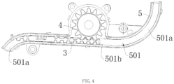
FIG. 4 is an assembly sectional view of a gear housing with an induction gear and a rack in the shift drive according to an embodiment of the present invention. -
FIG. 5A is a schematic diagram of connection between a straight rail section and a take-up release section according to a first preferred embodiment of the present invention. -
FIG. 5B is a schematic diagram of connection between a straight rail section and a take-up release section according to a second preferred embodiment of the present invention. -
FIG. 5C is a schematic diagram of connection between a straight rail section and a take-up release section according to a third preferred embodiment of the present invention. - In order to make those skilled in the art better understand the technical solutions in the present invention, the technical solutions in the embodiments of the present invention will be clearly and completely described in the following with reference to the accompanying drawings in the embodiments of the present application. Obviously, the described embodiments are only a part of the embodiments of the present invention, but not all of them. Based on the embodiments of the present invention, all other embodiments that are obtained by persons skilled in the art without making creative efforts shall fall within the protection scope of the present invention.
- It should be noted that when an element is referred to as being "disposed" on another element, it may be directly on another element or there may also be an intervening element. When one element is considered to be "connected" to another element, it may be connected directly to another element or there may be an intervening element as well. The terms "vertical," "horizontal," "left," "right" and other similar expressions used herein are used for illustrative purposes only and are not meant to be the only embodiment.
- Unless otherwise defined, all technical and scientific terms used herein have the same meanings as that are generally understood by those skilled in the art belonging to the technical field of the present invention. The terms used herein in the description of the invention are for purposes of describing specific embodiments only and are not intended to limit the invention. The terms "and/or" as used herein include any and all combinations of one or more related listed items.
- As shown in
FIGs. 1 to 4 , the embodiment of the present invention provides a shift drive which may comprise: an actuating mechanism 6 capable of being driven by a driving mechanism 1, the actuating mechanism 6 being for connection to a gearbox (not shown); arack 3 linked with the actuating mechanism 6, at least one end of therack 3 being capable of a recoverable deformation, therack 3 including a connection portion, the connection portion being connected to the actuating mechanism 6 through a connectingmember 301; a gear housing 5() provided with aninduction gear 4 that meshes with therack 3, thegear housing 5 having atrack slot 501 that receives therack 3 therein, thetrack slot 501 having a take-uprelease section 501a and astraight rail section 501b, wherein an end portion of therack 3 that is capable of a recoverable deformation can slide in or out of the take-uprelease section 501a, and the length of projection (the downward projection as shown inFIG. 3 ) of the take-uprelease section 501a on an extension line in the direction of the length of thestraight rail section 501b is less than the length of the track thereof. - In the shift drive of the embodiment of the present invention, by providing in the gear housing 5 a take-up
release section 501a having a length projected on the extension line in the length direction of thestraight rail section 501b that is less than the length of the track thereof, the end portion of therack 3 being received in thetrack slot 501, that is capable of a recoverable deformation, can slide in or out of the take-uprelease section 501a, so as to greatly extend the stroke of therack 3 under the premise of occupying the same space, so as to meet the requirement that the shift drive is applicable to the automatic gearbox which requires therack 3 has a long stroke. In this way, the shift drive according to the embodiment of the present invention can be applied to an automatic gearbox of an existing known construction without technical retrofitting, and can achieve the same shifting function as an electronic shifter. - Moreover, by changing the degree of bending, that is, the curvature, of the take-up
release section 501a, it is possible to obtain different lengths of thetrack slot 501 without changing thestraight rail section 501b, so as to meet the needs of different gearboxes for varying track lengths, such that the shift drive according to the embodiment of the present invention has better versatility and it is easy to realize the modularization of the product. - As shown in
FIGs. 1 and2 , the actuating mechanism 6 may comprise a screw 601 which is externally sleeved with aslider 604 connected with apush rod 602 by a universal joint structure, the other end of thepush rod 602 is connected to asocket shell 603 having aball socket 603a, and thesocket shell 603 is connected to a shift arm of the gearbox through theball socket 603a. - The driving mechanism 1 may comprise a
motor 101, which may drive the screw 601 to rotate. The specific driving mode may be the belt drive provided by the above-mentioned known embodiment, and details thereof are disclosed in the present invention by way of reference, and are not repeated herein. - Alternatively, a gear drive manner may be adopted. Specifically, an output shaft of the
motor 101 is provided with adriving gear 102, and the end of the screw 601 is provided with a drivengear 103, thedriving gear 102 may be directly meshed with the drivengear 103 to realize drive connection, or may be meshed with the drivengear 103 through anidle gear 104 to realize indirect drive. - The connecting
member 301 may be connected to theslider 604 or thepush rod 602 so as to be connected to the actuating mechanism 6. Specifically, theslider 604 or thepush rod 602 is provided with a connecting hole adapted to the connecting member, and the connectingmember 301 is inserted into the connecting hole. - The
rack 3 is substantially in the form of a flat strip having at least one end portion capable of a recoverable deformation (i.e., deformation not exceeding an elastic limit so that it can rebound to the original state), and the end portion is arranged corresponding to the take-uprelease section 501a such that at least the end portion of therack 3 can adapt to the curvature change of the take-uprelease section 501a and thus enter the take-uprelease section 501a. - Preferably, the
rack 3 as a whole may have the performance of a recoverable deformation. Thus, therack 3 is made of a flexible elastic material such as thermoplastic polyurethane elastomer rubber (TPU), so that therack 3 can be deformed in any direction such that therack 3 as a whole can be adaptively deformed in accordance with the shape of thetrack slot 501, so as to slide in or out of the take-uprelease section 501a, to meet the requirement that the shift drive is applicable to the automatic gearbox which requires therack 3 has a long stroke. - When the end portion of the
rack 3 that is capable of a recoverable deformation enters the take-uprelease section 501a, it may be radially bent such that the inner side of the rack 3 (the upper end as illustrated inFIG. 3 ) is compressed. This compression causes therack 3 to have a tendency to rebound radially outward, thereby exerting a force on the inner wall of the take-uprelease section 501a, thus increasing the frictional force between therack 3 and the inner wall of the take-uprelease section 501a, causing therack 3 to be hindered from sliding. - To this end, as shown in
FIG. 3 , therack 3 is provided with a plurality of longitudinally spacednotches 302 at least on a side wall near the end portion of the rack that is capable of a recoverable deformation, the plurality ofnotches 302 may provide therack 3 with a space for radial deformation upon entry into the take-uprelease section 501a, to reduce or even prevent the inner side of therack 3 from being compressed, thereby reducing the frictional force between therack 3 and the inner wall of the take-uprelease section 501a, ensuring that the end portion of therack 3 that is capable of a recoverable deformation is bent in a drag-reducing manner to enter the take-uprelease section 501a, thereby ensuring that therack 3 can slide smoothly. - The
gear housing 5 may be provided with a take-uprelease section 501a on at least one side of thestraight rail section 501b, that is, there may be at least one take-uprelease section 501a. Specifically, thestraight rail section 501b is located below theinduction gear 4, and the take-uprelease section 501a is disposed at at least one end of thestraight rail section 501b. Moreover, it is preferable that the take-uprelease section 501a is communicated with thestraight rail section 501b in a smooth transition so as to reduce the occurrence of blocking and unsmooth sliding of therack 3 at the connection between the two sections. - Further, the take-up
release sections 501a are preferably two, and specifically the two take-uprelease sections 501a may be formed by bending two ends of thestraight rail section 501b upward and downward, respectively, so that the space size of thegear housing 5 can be fully utilized to increase the stroke of therack 3 as much as possible. - The two take-up
release sections 501a and thestraight rail section 501b are preferably located in the same plane so that therack 3 can slide in or out of the take-uprelease sections 501a in a distortion-free manner, thereby maintaining the smoothness of sliding of therack 3. - Furthermore, with the two take-up
release sections 501a and thestraight rail section 501b being located in the same plane, the space in the vertical direction of thegear housing 5 can be fully utilized without increasing the space size in the direction perpendicular to thestraight rail section 501b, so that the compact structure is ensured while the dimensional structure design is optimized, and thus the structure of thegear housing 5 tends to be miniaturized. - The projection of the
straight rail section 501b on a projection plane perpendicular to a horizontal plane (which is a reference when the shift drive according to the embodiment of the present invention is actually used, and herein the horizontal plane is a plane perpendicular to a paper surface) is a straight line profile, which is in smooth transition to the take-uprelease sections 501a. - Specifically, as shown in
FIG. 5A , the projection of the take-uprelease section 501a (since it lies in the same plane as thestraight rail section 501b) on the projection plane described above is a circular arc profile, and thestraight rail section 501b and the take-uprelease sections 501a are connected in a tangential manner at the junction. - Alternatively, as shown in
FIG. 5B , the projections of the take-uprelease sections 501a on the projection plane described above are a circular arc profile and a straight line profile, the circular arc profile being tangent to thestraight rail section 501b and the straight line profile. - Alternatively, as shown in
FIG. 5C , the projections of the take-uprelease sections 501a on the projection plane described above are two circular arc profiles, the circular arc profile in the middle being tangent to thestraight rail section 501b and the other circular arc profile. - Of course, the above is merely an illustrative embodiment, and other possible profiles may be included in practice, and will not be exemplified herein.
- Further referring to
FIGs. 5A to 5C , since the take-uprelease sections 501a and thestraight rail section 501b are located on the same plane, the take-uprelease sections 501a can be line projected on the extension line in the longitudinal direction of thestraight rail section 501b. Then, the length of the take-uprelease sections 501a projected on the extension line in the length direction of thestraight rail section 501b (the length of the dashed lines inFIGs. 5A to 5C ) is L', and the length of the its track (actually the circumference thereof) is L, wherein L' < L. - Alternatively, the take-up
release sections 501a may also be projected on the projection plane defined by thestraight rail section 501b. Specifically, upper and lower surfaces of thestraight rail section 501b, or the horizontal surface when the shift drive according to the embodiment of the present invention is actually used, may be used as the projection surface. The projection length of the take-uprelease section 501a on such projection surface also satisfies the requirement of being less than its track length. - In this embodiment, the connection portion is a part of the structure of the
rack 3 itself, which may be a portion of therack 3 that is close to the middle, or a portion where therack 3 is connected to the connectingmember 301 may be defined as the connection portion. - Alternatively, the length of the
straight rail section 501b is set such that the connection portion can slide freely only therein along with the actuating mechanism 6. Therefore, a portion of therack 3 that moves only in thestraight rail section 501b and does not enter the take-uprelease section 501a may also be defined as the connection portion. - Following the description above, since the connection portion is connected to the driving mechanism 6 through the connecting
member 301, the driving mechanism 6 drives the connection portion to move through the connectingmember 301, thereby driving therack 3 to move in thetrack slot 501. - In general, realization of the function of the electronic shifter requires a high degree of transmission between the mechanical components, and requires synchronous transmission between the linkage components, that is, rigid transmission is required. Otherwise, the final measurement error is likely to be caused, resulting in shift misalignment.
- Specifically, in the present invention, when a shift signal triggers the
motor 101 to rotate,motor 101 is at a high speed and drives the actuating mechanism 6 from being stationary to move at a very high speed, resulting in a great acceleration. The driving mechanism 6 also converts this acceleration into an acting force applied to the connectingmember 301, which further applies the acting force to therack 3. Thus this causes the connectingmember 301 and therack 3 to be subjected to a great acting force, and the connectingmember 301 may be deformed. Likewise, since therack 3 is made of a flexible elastic material, it is also possible for therack 3 to be bent and deformed radially or stacked at a portion corresponding to the connectingmember 301. In this way, the transmission ratio between therack 3 and the driving mechanism 6 would be affected, causing the axial movement of thepush rod 602 to be out of synchronization with the rotation of theinduction gear 4 turned by therack 3, finally resulting in the measurement error of the magnetic field sensing element. - In order to avoid the above circumstance as much as possible, the connecting
member 301 can be connected to the connection portion of therack 3 through a rigid holding portion 7. The rigid holding portion 7 is preferably attached to therack 3 in a covering manner (the covering portion is the connection portion) so as to increase the connection strength between the two, and has a thickness greater than that of therack 3 so as to have a better rigidity. - The connecting
member 301 is preferably formed integrally with the rigid holding portion 7, and specifically may be formed as a protrusion extending from the rigid holding portion 7 toward the actuating mechanism 6 and inserted into a connecting hole provided in the actuating mechanism 6. In this way, the connectingmember 301 and the rigid holding portion 7 have the same thickness that is larger than the thickness of therack 3, thereby forming an increased thickness portion, and ensuring that the connectingmember 301 has a rigidity that enables therack 3 and the actuating mechanism 6 to be driven synchronously. - When the connecting
member 301 is quickly driven by the actuating mechanism 6, the connection portion covered by the rigid holding portion 7 and a rack section adjacent to the connection portion will not be bent and deformed or not be stacked, thereby ensuring better measurement accuracy. - Furthermore, to ensure the measurement accuracy, the
rack 3 is required to slide in or out of the take-uprelease section 501a smoothly. From the above, it can be seen that in the present invention, the end portion of therack 3 corresponding to the take-uprelease section 501a can smoothly enter the take-uprelease section 501a without stacking and blocking in such a manner that therack 3 is made of a flexible elastic material so as to have better deformation performance. - However, if the
rack 3 has better deformation performance, it will accordingly result in that the connection of therack 3 with the connectingmember 301 is not able to provide sufficient rigidity when it is driven rapidly by the actuating mechanism 6. - That is, for the purpose of the measurement accuracy, the
rack 3 is required to have better deformation performance, and the part thereof corresponding to the connection portion has better rigidity, both of which are diametrically opposed or even contradictory. - Therefore, how to maintain better rigidity at the part of the
rack 3 corresponding to the connectingmember 301 and at the same time making other parts of therack 3, especially the end portions, have better deformation capability are two contradictory technical problems. - In the present invention, by providing the rigid holding portion 7 on the connection portion of the
rack 3 made of a flexible elastic material and combining thenotches 302 provided on therack 3, the above-mentioned contradictory technical problems can be better solved. - The
rack 3 made of a flexible elastic material in combination with thenotch 302 provided thereon may enable therack 3 to have better deformation performance at least at the end thereof, so that therack 3 can be bent in a drag-reducing manner and enter the take-uprelease section 501a smoothly. The connection portion of therack 3 is connected to the connectingmember 301 through the rigid holding portion 7, so that therack 3 has better rigidity at a portion corresponding to the connection portion, to realize its synchronous transmission with the actuating mechanism 6. - Further, the length of the
straight rail section 501 is set such that the rigid holding portion 7 is limited to slide only within thestraight rail section 501b, that is, the rigid holding portion 7 moves linearly only within thestraight rail section 501b of thetrack slot 501 and does not enter the take-uprelease section 501a of thetrack slot 501. In this way, it is ensured that the connectingmember 301 and the rigid holding portion 7 will not be radially deformed and bent during sliding of therack 3 within thestraight rail section 501b. - As shown in
FIG. 3 , thegear housing 5 may be provided thereon with agear cover 8 adapted thereto. Similarly, thegear cover 8 is also provided with the same slot structure as thetrack slot 501, and the two slots form an inner space in which therack 3 is accommodated after thegear housing 5 and thegear cover 8 are combined, so that the sliding of therack 3 can be limited. - Further, the
gear cover 8 is provided thereon with anelongated opening 801 of which the connectingmember 301 extends out and which is corresponding to thestraight rail section 501b of thetrack slot 501, the connectingmember 301 passes through theelongated opening 801 to be connected to the actuating mechanism 6. - The specific principle of operation of the shift drive according to the embodiment of the present invention is that the
gear housing 5 is provided with a magnetic field sensing element (which may be for example, a Hall sensor) connected to the TCU by signal at a position thereof corresponding to theinduction gear 4. Themotor 101 rotates after it receives the shift signal generated by the TCU in signal connection to themotor 101 based on the user's triggering operation, to drive the screw 601 to rotate, and theslider 604 sleeving outside the screw 601 and engaged with the screw 601 is axially moved, and theslider 604 pushes thepush rod 602 to move, thereby driving the connectingmember 301 inserted into the connecting hole of theslider 604 or thepush rod 602 to move, then the connectingmember 301 causes therack 3 to slide in thetrack slot 501, so that therack 3 turns theinduction gear 4 to rotate by being engaged with theinduction gear 4. Rotation of theinduction gear 4 will produce a magnetic field change, so that the magnetic field sensing element senses the magnetic field change to realize the gear identification information. The TCU adjusts the rotational speed of themotor 101 or stops themotor 101 according to the gear identification information, moves thepush rod 602 connected to theslider 604 to a designated position, and shifts the gear. - Since the shift drive according to the embodiment of the present invention extends the stroke of the
rack 3, it is possible not only to apply a shift driving force to the gearbox by the actuating mechanism 6 after a P gear signal is received, but also to apply the shift driving force to the gearbox after R, N, and D gear signals are received, such that it is possible to realize electronic shifting in a gearbox that doesn't have a capacity of receiving R, N, and D gear signals. - It should be understood that the above description is for purposes of illustration and not for purposes of limitation. Many embodiments and many applications other than the examples provided will be apparent to those skilled in the art from reading the above description. Accordingly, the scope of the present teachings should not be determined with reference to the above description, but should be determined with reference to the foregoing.
Claims (7)
- A shift drive, comprising:an actuating mechanism (6) for connection to a gearbox;a rack (3) linked with the actuating mechanism (6), at least one end of the rack (3) being capable of a recoverable deformation, the rack (3) including a connection portion, the connection portion being connected to the actuating mechanism (6) through a connecting member (301);a gear housing (5) provided with an induction gear (4) that meshes with the rack (3), the gear housing (5) having a track slot (501) that receives the rack (3) therein, the track slot (501) having a straight rail section (501b) and a take-up release section (501a), wherein an end portion of the rack (3) that is recoverable from deformation can slide in or out of the take-up release section (501a), wherein the take-up release section (501a) has a length projected on an extension line in the length direction of the straight rail section (501b) is less than the length of its track length,characterized in that, the gear housing (5) is provided thereon with a gear cover (8) adapted thereto, and the gear cover (8) is provided thereon with an elongated opening (801) of which the connecting member (301) extends out.
- The shift drive according to claim 1, characterized in that the gear housing (5) is provided with the take-up release section (501a) on at least one side of the straight rail section (501b).
- The shift drive according to claim 1, characterized in that both ends of the straight rail section (501b) are bent in opposite directions, respectively, to form two take-up release sections which are located in the same plane as the straight rail section (501b).
- The shift drive according to claim 1, characterized in that, the connection portion is provided with a rigid holding portion (7) thereon, and the connecting member (310) is a protrusion extending from the rigid holding portion (7) toward the actuating mechanism (6) and inserted into a connecting hole provided in the actuating mechanism (6).
- The shift drive according to claim 1, characterized in that, the length of the straight rail section (501b) is set such that the connection portion can only slide freely therein along with the actuating mechanism (6).
- The shift drive according to claim 1 or 4, characterized in that, the rack (3) is provided with a plurality of longitudinally spaced notches (302) at least on a side wall near the end portion of the rack (3) that is capable of a recoverable deformation, so that the end portion of the rack (3) that is capable of a recoverable deformation is bent in a drag-reducing manner to enter the take-up release section (501a).
- The shift drive according to claim 1, characterized in that, the driving mechanism (6) comprises a motor (101), the gear housing (5) is provided with a magnetic field sensing element at a position corresponding to the induction gear (4), and the magnetic field sensing element and the motor (101) are in signal connection to a central control unit of an automobile.
Applications Claiming Priority (2)
| Application Number | Priority Date | Filing Date | Title |
|---|---|---|---|
| CN201810295940.6A CN108302198B (en) | 2018-03-30 | 2018-03-30 | Gear shift drive |
| PCT/CN2019/079999 WO2019184964A1 (en) | 2018-03-30 | 2019-03-28 | Shift driving device |
Publications (3)
| Publication Number | Publication Date |
|---|---|
| EP3779243A1 EP3779243A1 (en) | 2021-02-17 |
| EP3779243A4 EP3779243A4 (en) | 2021-12-01 |
| EP3779243B1 true EP3779243B1 (en) | 2023-08-23 |
Family
ID=62848275
Family Applications (1)
| Application Number | Title | Priority Date | Filing Date |
|---|---|---|---|
| EP19777417.7A Active EP3779243B1 (en) | 2018-03-30 | 2019-03-28 | Shift driving device |
Country Status (5)
| Country | Link |
|---|---|
| US (1) | US11566706B2 (en) |
| EP (1) | EP3779243B1 (en) |
| JP (1) | JP7256257B2 (en) |
| CN (1) | CN108302198B (en) |
| WO (1) | WO2019184964A1 (en) |
Families Citing this family (1)
| Publication number | Priority date | Publication date | Assignee | Title |
|---|---|---|---|---|
| CN108302198B (en) * | 2018-03-30 | 2025-05-27 | 法可赛(太仓)汽车配件有限公司 | Gear shift drive |
Family Cites Families (28)
| Publication number | Priority date | Publication date | Assignee | Title |
|---|---|---|---|---|
| GB190314089A (en) * | 1903-06-24 | 1904-04-21 | Joseph De Brouwer | Improvements in Apparatus for Discharging Coke from Through Gas Retorts. |
| US2755081A (en) * | 1951-10-08 | 1956-07-17 | Johnson Clarence | Garage door operators |
| JPS5854175A (en) * | 1981-09-22 | 1983-03-31 | 日産自動車株式会社 | Window glass lifting and falling apparatus |
| JPH0332107Y2 (en) * | 1985-10-31 | 1991-07-08 | ||
| DE3738416A1 (en) * | 1987-11-12 | 1989-05-24 | Bosch Gmbh Robert | DRIVE FOR ADJUSTING A MEMBER, IN PARTICULAR A LOCKING ELEMENT, WHICH IS PART OF THE CLOSING MECHANISM OF A COVER ELEMENT ASSIGNED INTO AN OPENING IN A MOTOR VEHICLE BODY |
| DE4016708C2 (en) * | 1990-05-24 | 1994-07-21 | Baumeister & Ostler Gmbh Co | Cover for the hold of a car |
| AU5696494A (en) * | 1992-12-10 | 1994-07-04 | Girotto, Pietro | Electromagnetic actuator for door units and the like |
| NZ330098A (en) * | 1998-03-31 | 2000-09-29 | Howick Engineering Ltd | A rack and pinion door drive device for an automatic door with rack having bifurcate transverse section to locate onto rail of door track |
| DE19803541B4 (en) * | 1998-01-30 | 2005-08-11 | Zf Sachs Ag | Actuating device for the automated actuation of a rotationally and translationally movable switching element of a manual transmission |
| JP2001071810A (en) * | 1999-09-07 | 2001-03-21 | Nissan Altia Co Ltd | Manufacture of expansion and contraction drive device and drive cord |
| US6694834B2 (en) | 2002-03-22 | 2004-02-24 | New Venture Gear, Inc. | Control system for transfer case range shift |
| DK1866556T3 (en) * | 2004-12-09 | 2010-10-04 | Kroeger Maskinfabrik As M | Articulated drive mechanism and dispenser comprising such a drive mechanism |
| JP5076840B2 (en) * | 2007-11-28 | 2012-11-21 | アイシン精機株式会社 | Opening / closing body driving rack belt and opening / closing body driving apparatus using the opening / closing body driving rack belt |
| CN100594861C (en) * | 2008-07-08 | 2010-03-24 | 北京航空航天大学 | Marker moving mechanism of visual fusion function trainer |
| WO2010070915A1 (en) * | 2008-12-19 | 2010-06-24 | 株式会社川渕機械技術研究所 | Linearly moving extendable mechanism and robot arm equipped with linearly moving extendable mechanism |
| JP2011085238A (en) * | 2009-10-19 | 2011-04-28 | Hi-Lex Corporation | Parking lock actuator |
| JP2011144832A (en) * | 2010-01-12 | 2011-07-28 | Tsubakimoto Chain Co | Engagement chain type advancing and retreating device |
| CN201902543U (en) | 2010-12-31 | 2011-07-20 | 三阳工业股份有限公司 | Modular gear-shifting driving device |
| CN202165585U (en) | 2011-06-30 | 2012-03-14 | 长城汽车股份有限公司 | Built-in AMT (Automated Mechanical Transmission) gear shifting drive system |
| JP5868296B2 (en) * | 2012-09-06 | 2016-02-24 | 株式会社東海理化電機製作所 | 2-axis position sensor and shift position sensor using the same |
| CN203047187U (en) * | 2013-01-17 | 2013-07-10 | 昆明理工大学 | Windscreen wiper |
| DE102014103741A1 (en) | 2014-03-19 | 2015-09-24 | Paul Vahle Gmbh & Co. Kg | Telescopic arm pantograph system for cranes, container cranes, ERTGs and conveyors |
| CN205136570U (en) * | 2015-11-04 | 2016-04-06 | 法可赛(太仓)汽车配件有限公司 | A electron gear shifting driver for car |
| CN205399614U (en) * | 2016-03-12 | 2016-07-27 | 慈溪三和智能卫浴有限公司 | Warm water toilet seat arc spouts water pipe assembly |
| JP6734364B2 (en) * | 2016-03-29 | 2020-08-05 | ライフロボティクス株式会社 | Linear motion telescopic mechanism and robot arm mechanism |
| CN106838303B (en) | 2017-03-31 | 2019-02-22 | 法可赛(太仓)汽车配件有限公司 | Shift Drives and Transmissions |
| CN108302198B (en) | 2018-03-30 | 2025-05-27 | 法可赛(太仓)汽车配件有限公司 | Gear shift drive |
| CN208057921U (en) * | 2018-03-30 | 2018-11-06 | 法可赛(太仓)汽车配件有限公司 | Shift driving device |
-
2018
- 2018-03-30 CN CN201810295940.6A patent/CN108302198B/en active Active
-
2019
- 2019-03-28 JP JP2021501069A patent/JP7256257B2/en active Active
- 2019-03-28 WO PCT/CN2019/079999 patent/WO2019184964A1/en not_active Ceased
- 2019-03-28 EP EP19777417.7A patent/EP3779243B1/en active Active
- 2019-03-28 US US17/043,246 patent/US11566706B2/en active Active
Also Published As
| Publication number | Publication date |
|---|---|
| EP3779243A1 (en) | 2021-02-17 |
| EP3779243A4 (en) | 2021-12-01 |
| CN108302198A (en) | 2018-07-20 |
| JP2021519406A (en) | 2021-08-10 |
| WO2019184964A1 (en) | 2019-10-03 |
| US20210025493A1 (en) | 2021-01-28 |
| CN108302198B (en) | 2025-05-27 |
| JP7256257B2 (en) | 2023-04-11 |
| US11566706B2 (en) | 2023-01-31 |
Similar Documents
| Publication | Publication Date | Title |
|---|---|---|
| US7146871B2 (en) | Vehicle running range switching device | |
| KR20080028795A (en) | Roller blind with guide rail without undercut | |
| US20180216390A1 (en) | Actuator and actuator for opening/closing vehicle door | |
| US9381900B2 (en) | Electric brake booster with transmission clearance compensation | |
| JPS612960A (en) | Gear device for converting rotary motion into linear motion | |
| EP1156240B1 (en) | Electric drive device for transmission | |
| US11566706B2 (en) | Shift drive | |
| JPWO2001031234A1 (en) | Electric drive unit for transmission | |
| US11746899B2 (en) | Transmission with 1 axis shift mechanism | |
| JPH08228456A (en) | Electric cylinder with electronic sensor | |
| EP0511351B1 (en) | Cable for accurate transmission of longitudinal motion | |
| CN208057921U (en) | Shift driving device | |
| JP4244650B2 (en) | Shifting operation device | |
| EP3553346A1 (en) | Gearshift actuator | |
| US6880420B2 (en) | Automatic control device for a motorized vehicle gearbox | |
| CN114183505A (en) | Gearbox and model car | |
| CN223868523U (en) | Gear shifting mechanism, gearbox and vehicle | |
| CN115539630B (en) | Gear shifting mechanism, powertrain and vehicle | |
| US11137055B2 (en) | Drive apparatus | |
| CN223318303U (en) | Gear shifting mechanism and mid-mounted transmission | |
| TWI294837B (en) | Shifting mechanism | |
| GB2384834A (en) | Gear shifting mechanism having a shift drum positioned by compression springs | |
| WO2014093860A1 (en) | Push down shifter with a cross joint | |
| US20080173117A1 (en) | Ball screw device | |
| US20250198507A1 (en) | Transmission control apparatus |
Legal Events
| Date | Code | Title | Description |
|---|---|---|---|
| STAA | Information on the status of an ep patent application or granted ep patent |
Free format text: STATUS: THE INTERNATIONAL PUBLICATION HAS BEEN MADE |
|
| PUAI | Public reference made under article 153(3) epc to a published international application that has entered the european phase |
Free format text: ORIGINAL CODE: 0009012 |
|
| STAA | Information on the status of an ep patent application or granted ep patent |
Free format text: STATUS: REQUEST FOR EXAMINATION WAS MADE |
|
| 17P | Request for examination filed |
Effective date: 20201030 |
|
| AK | Designated contracting states |
Kind code of ref document: A1 Designated state(s): AL AT BE BG CH CY CZ DE DK EE ES FI FR GB GR HR HU IE IS IT LI LT LU LV MC MK MT NL NO PL PT RO RS SE SI SK SM TR |
|
| AX | Request for extension of the european patent |
Extension state: BA ME |
|
| DAV | Request for validation of the european patent (deleted) | ||
| DAX | Request for extension of the european patent (deleted) | ||
| A4 | Supplementary search report drawn up and despatched |
Effective date: 20211103 |
|
| RIC1 | Information provided on ipc code assigned before grant |
Ipc: F16H 19/06 20060101ALI20211027BHEP Ipc: F16H 55/26 20060101ALI20211027BHEP Ipc: F16H 19/04 20060101ALI20211027BHEP Ipc: F16H 9/06 20060101ALI20211027BHEP Ipc: F16H 63/30 20060101ALI20211027BHEP Ipc: F16H 61/32 20060101AFI20211027BHEP |
|
| STAA | Information on the status of an ep patent application or granted ep patent |
Free format text: STATUS: EXAMINATION IS IN PROGRESS |
|
| 17Q | First examination report despatched |
Effective date: 20220920 |
|
| GRAP | Despatch of communication of intention to grant a patent |
Free format text: ORIGINAL CODE: EPIDOSNIGR1 |
|
| STAA | Information on the status of an ep patent application or granted ep patent |
Free format text: STATUS: GRANT OF PATENT IS INTENDED |
|
| INTG | Intention to grant announced |
Effective date: 20230314 |
|
| GRAS | Grant fee paid |
Free format text: ORIGINAL CODE: EPIDOSNIGR3 |
|
| GRAA | (expected) grant |
Free format text: ORIGINAL CODE: 0009210 |
|
| STAA | Information on the status of an ep patent application or granted ep patent |
Free format text: STATUS: THE PATENT HAS BEEN GRANTED |
|
| AK | Designated contracting states |
Kind code of ref document: B1 Designated state(s): AL AT BE BG CH CY CZ DE DK EE ES FI FR GB GR HR HU IE IS IT LI LT LU LV MC MK MT NL NO PL PT RO RS SE SI SK SM TR |
|
| REG | Reference to a national code |
Ref country code: GB Ref legal event code: FG4D |
|
| REG | Reference to a national code |
Ref country code: CH Ref legal event code: EP |
|
| REG | Reference to a national code |
Ref country code: IE Ref legal event code: FG4D |
|
| REG | Reference to a national code |
Ref country code: DE Ref legal event code: R096 Ref document number: 602019035680 Country of ref document: DE |
|
| REG | Reference to a national code |
Ref country code: LT Ref legal event code: MG9D |
|
| REG | Reference to a national code |
Ref country code: NL Ref legal event code: MP Effective date: 20230823 |
|
| REG | Reference to a national code |
Ref country code: AT Ref legal event code: MK05 Ref document number: 1602924 Country of ref document: AT Kind code of ref document: T Effective date: 20230823 |
|
| PG25 | Lapsed in a contracting state [announced via postgrant information from national office to epo] |
Ref country code: GR Free format text: LAPSE BECAUSE OF FAILURE TO SUBMIT A TRANSLATION OF THE DESCRIPTION OR TO PAY THE FEE WITHIN THE PRESCRIBED TIME-LIMIT Effective date: 20231124 |
|
| PG25 | Lapsed in a contracting state [announced via postgrant information from national office to epo] |
Ref country code: IS Free format text: LAPSE BECAUSE OF FAILURE TO SUBMIT A TRANSLATION OF THE DESCRIPTION OR TO PAY THE FEE WITHIN THE PRESCRIBED TIME-LIMIT Effective date: 20231223 |
|
| PG25 | Lapsed in a contracting state [announced via postgrant information from national office to epo] |
Ref country code: SE Free format text: LAPSE BECAUSE OF FAILURE TO SUBMIT A TRANSLATION OF THE DESCRIPTION OR TO PAY THE FEE WITHIN THE PRESCRIBED TIME-LIMIT Effective date: 20230823 Ref country code: RS Free format text: LAPSE BECAUSE OF FAILURE TO SUBMIT A TRANSLATION OF THE DESCRIPTION OR TO PAY THE FEE WITHIN THE PRESCRIBED TIME-LIMIT Effective date: 20230823 Ref country code: PT Free format text: LAPSE BECAUSE OF FAILURE TO SUBMIT A TRANSLATION OF THE DESCRIPTION OR TO PAY THE FEE WITHIN THE PRESCRIBED TIME-LIMIT Effective date: 20231226 Ref country code: NO Free format text: LAPSE BECAUSE OF FAILURE TO SUBMIT A TRANSLATION OF THE DESCRIPTION OR TO PAY THE FEE WITHIN THE PRESCRIBED TIME-LIMIT Effective date: 20231123 Ref country code: NL Free format text: LAPSE BECAUSE OF FAILURE TO SUBMIT A TRANSLATION OF THE DESCRIPTION OR TO PAY THE FEE WITHIN THE PRESCRIBED TIME-LIMIT Effective date: 20230823 Ref country code: LV Free format text: LAPSE BECAUSE OF FAILURE TO SUBMIT A TRANSLATION OF THE DESCRIPTION OR TO PAY THE FEE WITHIN THE PRESCRIBED TIME-LIMIT Effective date: 20230823 Ref country code: LT Free format text: LAPSE BECAUSE OF FAILURE TO SUBMIT A TRANSLATION OF THE DESCRIPTION OR TO PAY THE FEE WITHIN THE PRESCRIBED TIME-LIMIT Effective date: 20230823 Ref country code: IS Free format text: LAPSE BECAUSE OF FAILURE TO SUBMIT A TRANSLATION OF THE DESCRIPTION OR TO PAY THE FEE WITHIN THE PRESCRIBED TIME-LIMIT Effective date: 20231223 Ref country code: HR Free format text: LAPSE BECAUSE OF FAILURE TO SUBMIT A TRANSLATION OF THE DESCRIPTION OR TO PAY THE FEE WITHIN THE PRESCRIBED TIME-LIMIT Effective date: 20230823 Ref country code: GR Free format text: LAPSE BECAUSE OF FAILURE TO SUBMIT A TRANSLATION OF THE DESCRIPTION OR TO PAY THE FEE WITHIN THE PRESCRIBED TIME-LIMIT Effective date: 20231124 Ref country code: FI Free format text: LAPSE BECAUSE OF FAILURE TO SUBMIT A TRANSLATION OF THE DESCRIPTION OR TO PAY THE FEE WITHIN THE PRESCRIBED TIME-LIMIT Effective date: 20230823 Ref country code: AT Free format text: LAPSE BECAUSE OF FAILURE TO SUBMIT A TRANSLATION OF THE DESCRIPTION OR TO PAY THE FEE WITHIN THE PRESCRIBED TIME-LIMIT Effective date: 20230823 |
|
| PG25 | Lapsed in a contracting state [announced via postgrant information from national office to epo] |
Ref country code: PL Free format text: LAPSE BECAUSE OF FAILURE TO SUBMIT A TRANSLATION OF THE DESCRIPTION OR TO PAY THE FEE WITHIN THE PRESCRIBED TIME-LIMIT Effective date: 20230823 |
|
| PG25 | Lapsed in a contracting state [announced via postgrant information from national office to epo] |
Ref country code: ES Free format text: LAPSE BECAUSE OF FAILURE TO SUBMIT A TRANSLATION OF THE DESCRIPTION OR TO PAY THE FEE WITHIN THE PRESCRIBED TIME-LIMIT Effective date: 20230823 |
|
| PG25 | Lapsed in a contracting state [announced via postgrant information from national office to epo] |
Ref country code: SM Free format text: LAPSE BECAUSE OF FAILURE TO SUBMIT A TRANSLATION OF THE DESCRIPTION OR TO PAY THE FEE WITHIN THE PRESCRIBED TIME-LIMIT Effective date: 20230823 Ref country code: RO Free format text: LAPSE BECAUSE OF FAILURE TO SUBMIT A TRANSLATION OF THE DESCRIPTION OR TO PAY THE FEE WITHIN THE PRESCRIBED TIME-LIMIT Effective date: 20230823 Ref country code: ES Free format text: LAPSE BECAUSE OF FAILURE TO SUBMIT A TRANSLATION OF THE DESCRIPTION OR TO PAY THE FEE WITHIN THE PRESCRIBED TIME-LIMIT Effective date: 20230823 Ref country code: EE Free format text: LAPSE BECAUSE OF FAILURE TO SUBMIT A TRANSLATION OF THE DESCRIPTION OR TO PAY THE FEE WITHIN THE PRESCRIBED TIME-LIMIT Effective date: 20230823 Ref country code: DK Free format text: LAPSE BECAUSE OF FAILURE TO SUBMIT A TRANSLATION OF THE DESCRIPTION OR TO PAY THE FEE WITHIN THE PRESCRIBED TIME-LIMIT Effective date: 20230823 Ref country code: CZ Free format text: LAPSE BECAUSE OF FAILURE TO SUBMIT A TRANSLATION OF THE DESCRIPTION OR TO PAY THE FEE WITHIN THE PRESCRIBED TIME-LIMIT Effective date: 20230823 Ref country code: SK Free format text: LAPSE BECAUSE OF FAILURE TO SUBMIT A TRANSLATION OF THE DESCRIPTION OR TO PAY THE FEE WITHIN THE PRESCRIBED TIME-LIMIT Effective date: 20230823 |
|
| REG | Reference to a national code |
Ref country code: DE Ref legal event code: R097 Ref document number: 602019035680 Country of ref document: DE |
|
| PG25 | Lapsed in a contracting state [announced via postgrant information from national office to epo] |
Ref country code: IT Free format text: LAPSE BECAUSE OF FAILURE TO SUBMIT A TRANSLATION OF THE DESCRIPTION OR TO PAY THE FEE WITHIN THE PRESCRIBED TIME-LIMIT Effective date: 20230823 |
|
| PLBE | No opposition filed within time limit |
Free format text: ORIGINAL CODE: 0009261 |
|
| STAA | Information on the status of an ep patent application or granted ep patent |
Free format text: STATUS: NO OPPOSITION FILED WITHIN TIME LIMIT |
|
| 26N | No opposition filed |
Effective date: 20240524 |
|
| PG25 | Lapsed in a contracting state [announced via postgrant information from national office to epo] |
Ref country code: SI Free format text: LAPSE BECAUSE OF FAILURE TO SUBMIT A TRANSLATION OF THE DESCRIPTION OR TO PAY THE FEE WITHIN THE PRESCRIBED TIME-LIMIT Effective date: 20230823 |
|
| REG | Reference to a national code |
Ref country code: CH Ref legal event code: PL |
|
| PG25 | Lapsed in a contracting state [announced via postgrant information from national office to epo] |
Ref country code: BG Free format text: LAPSE BECAUSE OF FAILURE TO SUBMIT A TRANSLATION OF THE DESCRIPTION OR TO PAY THE FEE WITHIN THE PRESCRIBED TIME-LIMIT Effective date: 20230823 |
|
| PG25 | Lapsed in a contracting state [announced via postgrant information from national office to epo] |
Ref country code: LU Free format text: LAPSE BECAUSE OF NON-PAYMENT OF DUE FEES Effective date: 20240328 |
|
| PG25 | Lapsed in a contracting state [announced via postgrant information from national office to epo] |
Ref country code: MC Free format text: LAPSE BECAUSE OF FAILURE TO SUBMIT A TRANSLATION OF THE DESCRIPTION OR TO PAY THE FEE WITHIN THE PRESCRIBED TIME-LIMIT Effective date: 20230823 |
|
| GBPC | Gb: european patent ceased through non-payment of renewal fee |
Effective date: 20240328 |
|
| PG25 | Lapsed in a contracting state [announced via postgrant information from national office to epo] |
Ref country code: MC Free format text: LAPSE BECAUSE OF FAILURE TO SUBMIT A TRANSLATION OF THE DESCRIPTION OR TO PAY THE FEE WITHIN THE PRESCRIBED TIME-LIMIT Effective date: 20230823 Ref country code: LU Free format text: LAPSE BECAUSE OF NON-PAYMENT OF DUE FEES Effective date: 20240328 Ref country code: BG Free format text: LAPSE BECAUSE OF FAILURE TO SUBMIT A TRANSLATION OF THE DESCRIPTION OR TO PAY THE FEE WITHIN THE PRESCRIBED TIME-LIMIT Effective date: 20230823 |
|
| REG | Reference to a national code |
Ref country code: BE Ref legal event code: MM Effective date: 20240331 |
|
| PG25 | Lapsed in a contracting state [announced via postgrant information from national office to epo] |
Ref country code: BE Free format text: LAPSE BECAUSE OF NON-PAYMENT OF DUE FEES Effective date: 20240331 |
|
| PG25 | Lapsed in a contracting state [announced via postgrant information from national office to epo] |
Ref country code: GB Free format text: LAPSE BECAUSE OF NON-PAYMENT OF DUE FEES Effective date: 20240328 |
|
| PG25 | Lapsed in a contracting state [announced via postgrant information from national office to epo] |
Ref country code: FR Free format text: LAPSE BECAUSE OF NON-PAYMENT OF DUE FEES Effective date: 20240331 |
|
| PG25 | Lapsed in a contracting state [announced via postgrant information from national office to epo] |
Ref country code: IE Free format text: LAPSE BECAUSE OF NON-PAYMENT OF DUE FEES Effective date: 20240328 |
|
| PG25 | Lapsed in a contracting state [announced via postgrant information from national office to epo] |
Ref country code: IE Free format text: LAPSE BECAUSE OF NON-PAYMENT OF DUE FEES Effective date: 20240328 Ref country code: GB Free format text: LAPSE BECAUSE OF NON-PAYMENT OF DUE FEES Effective date: 20240328 Ref country code: FR Free format text: LAPSE BECAUSE OF NON-PAYMENT OF DUE FEES Effective date: 20240331 Ref country code: BE Free format text: LAPSE BECAUSE OF NON-PAYMENT OF DUE FEES Effective date: 20240331 Ref country code: CH Free format text: LAPSE BECAUSE OF NON-PAYMENT OF DUE FEES Effective date: 20240331 |
|
| PG25 | Lapsed in a contracting state [announced via postgrant information from national office to epo] |
Ref country code: CY Free format text: LAPSE BECAUSE OF FAILURE TO SUBMIT A TRANSLATION OF THE DESCRIPTION OR TO PAY THE FEE WITHIN THE PRESCRIBED TIME-LIMIT; INVALID AB INITIO Effective date: 20190328 |
|
| PG25 | Lapsed in a contracting state [announced via postgrant information from national office to epo] |
Ref country code: HU Free format text: LAPSE BECAUSE OF FAILURE TO SUBMIT A TRANSLATION OF THE DESCRIPTION OR TO PAY THE FEE WITHIN THE PRESCRIBED TIME-LIMIT; INVALID AB INITIO Effective date: 20190328 |
|
| PG25 | Lapsed in a contracting state [announced via postgrant information from national office to epo] |
Ref country code: TR Free format text: LAPSE BECAUSE OF FAILURE TO SUBMIT A TRANSLATION OF THE DESCRIPTION OR TO PAY THE FEE WITHIN THE PRESCRIBED TIME-LIMIT Effective date: 20230823 |
|
| PGFP | Annual fee paid to national office [announced via postgrant information from national office to epo] |
Ref country code: DE Payment date: 20260327 Year of fee payment: 8 |