EP3779134A1 - Motorcycle - Google Patents
Motorcycle Download PDFInfo
- Publication number
- EP3779134A1 EP3779134A1 EP18912002.5A EP18912002A EP3779134A1 EP 3779134 A1 EP3779134 A1 EP 3779134A1 EP 18912002 A EP18912002 A EP 18912002A EP 3779134 A1 EP3779134 A1 EP 3779134A1
- Authority
- EP
- European Patent Office
- Prior art keywords
- battery
- remaining amount
- engine
- power
- catalytic device
- Prior art date
- Legal status (The legal status is an assumption and is not a legal conclusion. Google has not performed a legal analysis and makes no representation as to the accuracy of the status listed.)
- Granted
Links
Images




Classifications
-
- F—MECHANICAL ENGINEERING; LIGHTING; HEATING; WEAPONS; BLASTING
- F01—MACHINES OR ENGINES IN GENERAL; ENGINE PLANTS IN GENERAL; STEAM ENGINES
- F01N—GAS-FLOW SILENCERS OR EXHAUST APPARATUS FOR MACHINES OR ENGINES IN GENERAL; GAS-FLOW SILENCERS OR EXHAUST APPARATUS FOR INTERNAL-COMBUSTION ENGINES
- F01N3/00—Exhaust or silencing apparatus having means for purifying, rendering innocuous, or otherwise treating exhaust
- F01N3/08—Exhaust or silencing apparatus having means for purifying, rendering innocuous, or otherwise treating exhaust for rendering innocuous
- F01N3/10—Exhaust or silencing apparatus having means for purifying, rendering innocuous, or otherwise treating exhaust for rendering innocuous by thermal or catalytic conversion of noxious components of exhaust
- F01N3/18—Exhaust or silencing apparatus having means for purifying, rendering innocuous, or otherwise treating exhaust for rendering innocuous by thermal or catalytic conversion of noxious components of exhaust characterised by methods of operation; Control
- F01N3/20—Exhaust or silencing apparatus having means for purifying, rendering innocuous, or otherwise treating exhaust for rendering innocuous by thermal or catalytic conversion of noxious components of exhaust characterised by methods of operation; Control specially adapted for catalytic conversion
- F01N3/2006—Periodically heating or cooling catalytic reactors, e.g. at cold starting or overheating
- F01N3/2013—Periodically heating or cooling catalytic reactors, e.g. at cold starting or overheating using electric or magnetic heating means
-
- B—PERFORMING OPERATIONS; TRANSPORTING
- B60—VEHICLES IN GENERAL
- B60K—ARRANGEMENT OR MOUNTING OF PROPULSION UNITS OR OF TRANSMISSIONS IN VEHICLES; ARRANGEMENT OR MOUNTING OF PLURAL DIVERSE PRIME-MOVERS IN VEHICLES; AUXILIARY DRIVES FOR VEHICLES; INSTRUMENTATION OR DASHBOARDS FOR VEHICLES; ARRANGEMENTS IN CONNECTION WITH COOLING, AIR INTAKE, GAS EXHAUST OR FUEL SUPPLY OF PROPULSION UNITS IN VEHICLES
- B60K6/00—Arrangement or mounting of plural diverse prime-movers for mutual or common propulsion, e.g. hybrid propulsion systems comprising electric motors and internal combustion engines
- B60K6/20—Arrangement or mounting of plural diverse prime-movers for mutual or common propulsion, e.g. hybrid propulsion systems comprising electric motors and internal combustion engines the prime-movers consisting of electric motors and internal combustion engines, e.g. HEVs
- B60K6/42—Arrangement or mounting of plural diverse prime-movers for mutual or common propulsion, e.g. hybrid propulsion systems comprising electric motors and internal combustion engines the prime-movers consisting of electric motors and internal combustion engines, e.g. HEVs characterised by the architecture of the hybrid electric vehicle
- B60K6/46—Series type
-
- B—PERFORMING OPERATIONS; TRANSPORTING
- B60—VEHICLES IN GENERAL
- B60L—PROPULSION OF ELECTRICALLY-PROPELLED VEHICLES; SUPPLYING ELECTRIC POWER FOR AUXILIARY EQUIPMENT OF ELECTRICALLY-PROPELLED VEHICLES; ELECTRODYNAMIC BRAKE SYSTEMS FOR VEHICLES IN GENERAL; MAGNETIC SUSPENSION OR LEVITATION FOR VEHICLES; MONITORING OPERATING VARIABLES OF ELECTRICALLY-PROPELLED VEHICLES; ELECTRIC SAFETY DEVICES FOR ELECTRICALLY-PROPELLED VEHICLES
- B60L3/00—Electric devices on electrically-propelled vehicles for safety purposes; Monitoring operating variables, e.g. speed, deceleration or energy consumption
-
- B—PERFORMING OPERATIONS; TRANSPORTING
- B60—VEHICLES IN GENERAL
- B60L—PROPULSION OF ELECTRICALLY-PROPELLED VEHICLES; SUPPLYING ELECTRIC POWER FOR AUXILIARY EQUIPMENT OF ELECTRICALLY-PROPELLED VEHICLES; ELECTRODYNAMIC BRAKE SYSTEMS FOR VEHICLES IN GENERAL; MAGNETIC SUSPENSION OR LEVITATION FOR VEHICLES; MONITORING OPERATING VARIABLES OF ELECTRICALLY-PROPELLED VEHICLES; ELECTRIC SAFETY DEVICES FOR ELECTRICALLY-PROPELLED VEHICLES
- B60L50/00—Electric propulsion with power supplied within the vehicle
- B60L50/10—Electric propulsion with power supplied within the vehicle using propulsion power supplied by engine-driven generators, e.g. generators driven by combustion engines
- B60L50/15—Electric propulsion with power supplied within the vehicle using propulsion power supplied by engine-driven generators, e.g. generators driven by combustion engines with additional electric power supply
-
- B—PERFORMING OPERATIONS; TRANSPORTING
- B60—VEHICLES IN GENERAL
- B60W—CONJOINT CONTROL OF VEHICLE SUB-UNITS OF DIFFERENT TYPE OR DIFFERENT FUNCTION; CONTROL SYSTEMS SPECIALLY ADAPTED FOR HYBRID VEHICLES; ROAD VEHICLE DRIVE CONTROL SYSTEMS FOR PURPOSES NOT RELATED TO THE CONTROL OF A PARTICULAR SUB-UNIT
- B60W10/00—Conjoint control of vehicle sub-units of different type or different function
- B60W10/24—Conjoint control of vehicle sub-units of different type or different function including control of energy storage means
- B60W10/26—Conjoint control of vehicle sub-units of different type or different function including control of energy storage means for electrical energy, e.g. batteries or capacitors
-
- B—PERFORMING OPERATIONS; TRANSPORTING
- B60—VEHICLES IN GENERAL
- B60W—CONJOINT CONTROL OF VEHICLE SUB-UNITS OF DIFFERENT TYPE OR DIFFERENT FUNCTION; CONTROL SYSTEMS SPECIALLY ADAPTED FOR HYBRID VEHICLES; ROAD VEHICLE DRIVE CONTROL SYSTEMS FOR PURPOSES NOT RELATED TO THE CONTROL OF A PARTICULAR SUB-UNIT
- B60W20/00—Control systems specially adapted for hybrid vehicles
-
- B—PERFORMING OPERATIONS; TRANSPORTING
- B62—LAND VEHICLES FOR TRAVELLING OTHERWISE THAN ON RAILS
- B62K—CYCLES; CYCLE FRAMES; CYCLE STEERING DEVICES; RIDER-OPERATED TERMINAL CONTROLS SPECIALLY ADAPTED FOR CYCLES; CYCLE AXLE SUSPENSIONS; CYCLE SIDECARS, FORECARS, OR THE LIKE
- B62K11/00—Motorcycles, engine-assisted cycles or motor scooters with one or two wheels
- B62K11/02—Frames
- B62K11/10—Frames characterised by the engine being over or beside driven rear wheel
-
- B—PERFORMING OPERATIONS; TRANSPORTING
- B62—LAND VEHICLES FOR TRAVELLING OTHERWISE THAN ON RAILS
- B62M—RIDER PROPULSION OF WHEELED VEHICLES OR SLEDGES; POWERED PROPULSION OF SLEDGES OR SINGLE-TRACK CYCLES; TRANSMISSIONS SPECIALLY ADAPTED FOR SUCH VEHICLES
- B62M7/00—Motorcycles characterised by position of motor or engine
- B62M7/02—Motorcycles characterised by position of motor or engine with engine between front and rear wheels
-
- F—MECHANICAL ENGINEERING; LIGHTING; HEATING; WEAPONS; BLASTING
- F01—MACHINES OR ENGINES IN GENERAL; ENGINE PLANTS IN GENERAL; STEAM ENGINES
- F01N—GAS-FLOW SILENCERS OR EXHAUST APPARATUS FOR MACHINES OR ENGINES IN GENERAL; GAS-FLOW SILENCERS OR EXHAUST APPARATUS FOR INTERNAL-COMBUSTION ENGINES
- F01N3/00—Exhaust or silencing apparatus having means for purifying, rendering innocuous, or otherwise treating exhaust
- F01N3/08—Exhaust or silencing apparatus having means for purifying, rendering innocuous, or otherwise treating exhaust for rendering innocuous
- F01N3/10—Exhaust or silencing apparatus having means for purifying, rendering innocuous, or otherwise treating exhaust for rendering innocuous by thermal or catalytic conversion of noxious components of exhaust
- F01N3/101—Three-way catalysts
-
- F—MECHANICAL ENGINEERING; LIGHTING; HEATING; WEAPONS; BLASTING
- F01—MACHINES OR ENGINES IN GENERAL; ENGINE PLANTS IN GENERAL; STEAM ENGINES
- F01N—GAS-FLOW SILENCERS OR EXHAUST APPARATUS FOR MACHINES OR ENGINES IN GENERAL; GAS-FLOW SILENCERS OR EXHAUST APPARATUS FOR INTERNAL-COMBUSTION ENGINES
- F01N9/00—Electrical control of exhaust gas treating apparatus
-
- F—MECHANICAL ENGINEERING; LIGHTING; HEATING; WEAPONS; BLASTING
- F01—MACHINES OR ENGINES IN GENERAL; ENGINE PLANTS IN GENERAL; STEAM ENGINES
- F01N—GAS-FLOW SILENCERS OR EXHAUST APPARATUS FOR MACHINES OR ENGINES IN GENERAL; GAS-FLOW SILENCERS OR EXHAUST APPARATUS FOR INTERNAL-COMBUSTION ENGINES
- F01N2240/00—Combination or association of two or more different exhaust treating devices, or of at least one such device with an auxiliary device, not covered by indexing codes F01N2230/00 or F01N2250/00, one of the devices being
- F01N2240/16—Combination or association of two or more different exhaust treating devices, or of at least one such device with an auxiliary device, not covered by indexing codes F01N2230/00 or F01N2250/00, one of the devices being an electric heater, i.e. a resistance heater
-
- F—MECHANICAL ENGINEERING; LIGHTING; HEATING; WEAPONS; BLASTING
- F01—MACHINES OR ENGINES IN GENERAL; ENGINE PLANTS IN GENERAL; STEAM ENGINES
- F01N—GAS-FLOW SILENCERS OR EXHAUST APPARATUS FOR MACHINES OR ENGINES IN GENERAL; GAS-FLOW SILENCERS OR EXHAUST APPARATUS FOR INTERNAL-COMBUSTION ENGINES
- F01N2590/00—Exhaust or silencing apparatus adapted to particular use, e.g. for military applications, airplanes, submarines
- F01N2590/04—Exhaust or silencing apparatus adapted to particular use, e.g. for military applications, airplanes, submarines for motorcycles
-
- F—MECHANICAL ENGINEERING; LIGHTING; HEATING; WEAPONS; BLASTING
- F01—MACHINES OR ENGINES IN GENERAL; ENGINE PLANTS IN GENERAL; STEAM ENGINES
- F01N—GAS-FLOW SILENCERS OR EXHAUST APPARATUS FOR MACHINES OR ENGINES IN GENERAL; GAS-FLOW SILENCERS OR EXHAUST APPARATUS FOR INTERNAL-COMBUSTION ENGINES
- F01N2590/00—Exhaust or silencing apparatus adapted to particular use, e.g. for military applications, airplanes, submarines
- F01N2590/11—Exhaust or silencing apparatus adapted to particular use, e.g. for military applications, airplanes, submarines for hybrid vehicles
-
- F—MECHANICAL ENGINEERING; LIGHTING; HEATING; WEAPONS; BLASTING
- F01—MACHINES OR ENGINES IN GENERAL; ENGINE PLANTS IN GENERAL; STEAM ENGINES
- F01N—GAS-FLOW SILENCERS OR EXHAUST APPARATUS FOR MACHINES OR ENGINES IN GENERAL; GAS-FLOW SILENCERS OR EXHAUST APPARATUS FOR INTERNAL-COMBUSTION ENGINES
- F01N2900/00—Details of electrical control or of the monitoring of the exhaust gas treating apparatus
- F01N2900/04—Methods of control or diagnosing
- F01N2900/0412—Methods of control or diagnosing using pre-calibrated maps, tables or charts
-
- F—MECHANICAL ENGINEERING; LIGHTING; HEATING; WEAPONS; BLASTING
- F01—MACHINES OR ENGINES IN GENERAL; ENGINE PLANTS IN GENERAL; STEAM ENGINES
- F01N—GAS-FLOW SILENCERS OR EXHAUST APPARATUS FOR MACHINES OR ENGINES IN GENERAL; GAS-FLOW SILENCERS OR EXHAUST APPARATUS FOR INTERNAL-COMBUSTION ENGINES
- F01N2900/00—Details of electrical control or of the monitoring of the exhaust gas treating apparatus
- F01N2900/06—Parameters used for exhaust control or diagnosing
- F01N2900/10—Parameters used for exhaust control or diagnosing said parameters being related to the vehicle or its components
- F01N2900/104—Battery status
-
- Y—GENERAL TAGGING OF NEW TECHNOLOGICAL DEVELOPMENTS; GENERAL TAGGING OF CROSS-SECTIONAL TECHNOLOGIES SPANNING OVER SEVERAL SECTIONS OF THE IPC; TECHNICAL SUBJECTS COVERED BY FORMER USPC CROSS-REFERENCE ART COLLECTIONS [XRACs] AND DIGESTS
- Y02—TECHNOLOGIES OR APPLICATIONS FOR MITIGATION OR ADAPTATION AGAINST CLIMATE CHANGE
- Y02A—TECHNOLOGIES FOR ADAPTATION TO CLIMATE CHANGE
- Y02A50/00—TECHNOLOGIES FOR ADAPTATION TO CLIMATE CHANGE in human health protection, e.g. against extreme weather
- Y02A50/20—Air quality improvement or preservation, e.g. vehicle emission control or emission reduction by using catalytic converters
-
- Y—GENERAL TAGGING OF NEW TECHNOLOGICAL DEVELOPMENTS; GENERAL TAGGING OF CROSS-SECTIONAL TECHNOLOGIES SPANNING OVER SEVERAL SECTIONS OF THE IPC; TECHNICAL SUBJECTS COVERED BY FORMER USPC CROSS-REFERENCE ART COLLECTIONS [XRACs] AND DIGESTS
- Y02—TECHNOLOGIES OR APPLICATIONS FOR MITIGATION OR ADAPTATION AGAINST CLIMATE CHANGE
- Y02T—CLIMATE CHANGE MITIGATION TECHNOLOGIES RELATED TO TRANSPORTATION
- Y02T10/00—Road transport of goods or passengers
- Y02T10/10—Internal combustion engine [ICE] based vehicles
- Y02T10/12—Improving ICE efficiencies
-
- Y—GENERAL TAGGING OF NEW TECHNOLOGICAL DEVELOPMENTS; GENERAL TAGGING OF CROSS-SECTIONAL TECHNOLOGIES SPANNING OVER SEVERAL SECTIONS OF THE IPC; TECHNICAL SUBJECTS COVERED BY FORMER USPC CROSS-REFERENCE ART COLLECTIONS [XRACs] AND DIGESTS
- Y02—TECHNOLOGIES OR APPLICATIONS FOR MITIGATION OR ADAPTATION AGAINST CLIMATE CHANGE
- Y02T—CLIMATE CHANGE MITIGATION TECHNOLOGIES RELATED TO TRANSPORTATION
- Y02T10/00—Road transport of goods or passengers
- Y02T10/10—Internal combustion engine [ICE] based vehicles
- Y02T10/40—Engine management systems
Definitions
- the present invention relates to a motorcycle.
- Patent Literature 1 Japanese Patent Laid-Open No. 2017-52500
- Patent Literature 1 it requires a long time to heat when a small electric heater is used. Therefore, a case is assumed in which a temperature of a catalytic device has not reached a catalytic active temperature by the time at which it is desired to start power generation, making it impossible to prepare for power generation.
- An object of the present invention is to provide a motorcycle with which the temperature setting of a catalytic device, which is a preparation for power generation, can be performed in time.
- the present invention is a motorcycle that includes an engine (41), a power generator (48) driven by the engine (41), a battery (58) for storing electric power generated by the power generator (48), an electric motor (43) operated by the electric power of the battery (58), a drive wheel (16) driven by the electric motor (43), and a catalytic device (87) for purifying exhaust gas discharged from the engine (41), in which a heating device (88) for heating the catalytic device (87) is provided, a predicted remaining amount of the battery (58) after a predetermined time elapse is calculated based on a remaining amount of the battery (58) and an amount to be decreased per unit time from the remaining amount of the battery (58), and the catalytic device (87) is heated by means of the heating device (88) when the predicted remaining amount has reached a predetermined value.
- the predetermined time may vary depending on a temperature of the catalytic device (87).
- the temperature of the catalytic device (87) may be calculated from a prediction curve.
- a power mode in which the remaining amount of the battery (58) for starting power generation of the power generator (48) is a first set value rp and an eco mode in which the remaining amount of the battery (58) for starting power generation of the power generator (48) is a second set value re that is lower than the first set value rp may be provided, and in the eco mode, the catalytic device (87) is heated.
- the present invention is a motorcycle that includes an engine (41), a power generator (48) driven by the engine (41), a battery (58) for storing electric power generated by the power generator (48), an electric motor (43) operated by the electric power of the battery (58), a drive wheel (16) driven by the electric motor (43), and a catalytic device (87) for purifying exhaust gas discharged from the engine (41), in which a heating device (88) for heating the catalytic device (87) is provided, a power mode in which the remaining amount of the battery (58) for starting power generation of the power generator (48) is a first set value rp and an eco mode in which the remaining amount of the battery (58) for starting power generation of the power generator (48) is a second set value re that is lower than the first set value rp are provided, and in the power mode, the catalytic device (87) is heated after the engine (41) has stopped.
- the present invention includes the heating device for heating the catalytic device and calculates the predicted remaining amount of the battery after a predetermined time elapse based on the remaining amount of the battery and the amount to be decreased per unit time from the remaining amount of the battery so as to heat the catalytic device by means of the heating device when the predicted remaining amount has reached a predetermined value
- the temperature setting of the catalytic device which is a preparation for power generation, can be performed in time by predicting the remaining amount of the battery after a predetermined time elapse.
- a preparation for power generation can be made in time according to the change in the temperature of the catalytic device.
- the temperature of the catalytic device is calculated from a prediction curve, the temperature of the catalytic device can be obtained quickly by creating a prediction curve in advance, and cost can also be reduced by omitting a temperature sensor.
- the power mode in which the remaining amount of the battery for starting power generation of the power generator is the first set value rp and the eco mode in which the remaining amount of the battery for starting power generation of the power generator is the second set value re that is lower than the first set value rp are provided so as to heat the catalytic device in the eco mode, it is possible to meet a wide range of requests from a driver by providing different battery remaining amount modes. Further, in the eco mode, since it is only necessary to heat the catalytic device in time for power generation, power consumption of the heating device can be suppressed.
- the present invention includes the heating device that heats the catalytic device, in which the power mode in which the remaining amount of the battery for starting power generation of the power generator is the first set value rp and the eco mode in which the remaining amount of the battery for starting power generation of the power generator is the second set value re that is lower than the first set value rp are provided, and in the power mode, the temperature of the catalytic device does not easily decrease as the catalytic device is heated after the engine is stopped, so that heating time can be shortened and power consumption of the heating device can be suppressed due to the heating time reduction.
- a reference sign FR indicates a front of the vehicle body
- a reference sign UP indicates an upper side of the vehicle body
- a reference sign LH indicates a left side of the vehicle body.
- Fig. 1 is a left side view showing a motorcycle 10 according to an embodiment of the present invention.
- the motorcycle 10 includes a body frame 11 serving as a skeleton, a front wheel 13 supported on a front end portion of the body frame 11 via a front fork 12, and a rear wheel 16 supported on a lower portion of the body frame 11 via a power unit 14.
- the motorcycle 10 is a saddle-riding type vehicle of a scooter type in which an occupant sits by straddling a seat 17 disposed above the power unit 14 and the rear wheel 16, and includes a vehicle body frame 11 and a vehicle body cover 20 that covers the periphery of the vehicle body frame 11.
- the body frame 11 includes a head pipe 21, a down frame 22, a pair of left and right under frames 23, a pair of left and right rear frames 24, and a pair of left and right step frames 26.
- the head pipe 21 is provided at a front end portion of the vehicle body frame 11.
- the down frame 22 extends downward from the head pipe 21.
- the left and right under frames 23 extend rearward from the left and right sides of a lower portion of the down frame 22, respectively.
- the left and right rear frames 24 extend rearward and obliquely upward from rear ends of the left and right under frames 23, respectively.
- the left and right step frames 26 are connected to the down frame 22 and the left and right under frames 23, respectively.
- the front fork 12 has a handle 31 attached to an upper portion of the front fork 12, and supports the front wheel 13 at a lower end portion of the front fork 12 via an axle 32.
- the power unit 14 is supported by a pair of left and right pivot plates 35 respectively attached to the left and right under frames 23 and the left and right rear frames 24 via a link mechanism 36 so as to be swingable up and down.
- a vehicle body side connecting portion 14a is provided at a lower portion of the power unit 14, and the vehicle body side connecting portion 14a is connected to the link mechanism 36.
- the power unit 14 includes an engine 41 provided at a front portion of the power unit 14, an electric motor 43 attached to a rear portion of a crankcase 42 of the engine 41, and an output shaft 44 connected to the electric motor 43 via a speed reduction mechanism (not shown).
- a reference sign 43a denotes a rotating shaft of the electric motor 43.
- the engine 41 is a four-cycle engine, and includes the crankcase 42 and a cylinder portion 46 that protrudes forward from a front end portion of the crankcase 42.
- the crankcase 42 accommodates a crankshaft 47 extending in a direction of a vehicle width and a power generator 48 provided around the crankshaft 47.
- the cylinder portion 46 includes a cylinder head 51, and the cylinder head 51 includes an intake device 52 connected to an upper portion of the cylinder head 51 and an exhaust device 53 connected to a lower portion of the cylinder head 51.
- the intake device 52 includes an air cleaner 55 attached to an upper portion of the power unit 14.
- the rear wheel 16 is attached to the output shaft 44.
- the rear wheel 16 is driven by the electric motor 43.
- the power generator 48 includes a stator (not shown) attached to the crankcase 42 and a rotor (not shown) attached to the crankshaft 47 and disposed inside the stator, and the rotor rotates together with the crankshaft 47 to generate electric power.
- a rear cushion unit 57 is passed between a rear end portion of the power unit 14 and a rear portion of one of the left and right rear frames 24 (the left side rear frame 24).
- a battery 58 is disposed between the left and right under frames 23 and between the left and right step frames 26.
- the battery 58 stores electric power generated by the power generator 48.
- the electric motor 43 is operated by the electric power stored in the battery 58, and the rear wheel 16 that is a drive wheel is driven by the electric motor 43.
- the battery 58 is provided with a remaining amount meter (not shown) that measures a remaining amount of stored electric power (amount of stored power).
- a storage box 61 and a fuel tank 62 provided behind the storage box 61 are attached to the left and right rear frames 24.
- the storage box 61 and the fuel tank 62 are disposed below the seat 17.
- a stand 64 is attached to a lower portion of the crankcase 42.
- An ECU (Engine Control Unit) 65 that controls operation of the engine 41 is provided at a rear portion of the head pipe 21.
- the vehicle body cover 20 includes a front cover 71, a pair of left and right leg shields 72, a pair of left and right floor steps 73, a pair of left and right side skirts 74, a pair of left and right body covers 76, and a handle cover 77.
- the front cover 71 covers a front of the front fork 12.
- the left and right leg shields 72 are connected to both side edges of the front cover 71 and cover legs of a driver seated on the seat 17 from the front.
- the left and right floor steps 73 extend rearward from lower end portions of the left and right leg shields 72 and serve as a footrest for the driver.
- the left and right side skirts 74 extend downward from both side edges of the left and right floor steps 73, respectively.
- the left and right body covers 76 cover lower portions of both side portions of the seat 17.
- the handle cover 77 covers a central portion of the handle 31.
- the battery 58 is disposed below the left and right floor steps 73.
- the battery 58 is covered with the vehicle body cover 20 including the left and right floor steps 73, the left and right side skirts 74, and the like.
- the front wheel 13 is covered with a front fender 81 from above, and the rear wheel 16 is covered with a rear fender 82 from above.
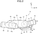
- Fig. 2 is a right side view showing the power unit 14.
- the crankcase 42 of the power unit 14 includes a crankcase main body 42a provided on the side of the engine 41, and a rear extension portion 42b extending rearward from the crankcase main body 42a.
- the rear extension portion 42b is provided with the electric motor 43, the speed reduction mechanism (not shown), and the output shaft 44.
- the exhaust device 53 includes an exhaust pipe 85 extending downward and rearward from the cylinder head 51, a muffler 86 connected to a rear end portion of the exhaust pipe 85, and a catalytic device 87 provided midway of the exhaust pipe 85 (specifically, at a position near the cylinder head 51), and a heating device 88 capable of heating the catalytic device 87.
- the catalytic device 87 purifies unpurified components such as a hydrocarbon (HC), a carbon monoxide (CO), a nitrogen oxide (NOx), and the like contained in exhaust gas flowing in the exhaust pipe 85 by removing them with a catalyst.
- unpurified components such as a hydrocarbon (HC), a carbon monoxide (CO), a nitrogen oxide (NOx), and the like contained in exhaust gas flowing in the exhaust pipe 85 by removing them with a catalyst.
- the heating device 88 is formed of an electric heater disposed so as to surround the catalytic device 87, and raises the temperature of the catalyst included in the catalytic device 87 to a temperature at which the catalyst is activated (a catalytic active temperature).
- a catalytic active temperature a temperature at which the catalyst is activated.
- the exhaust pipe 85 extends back and forth on a side of a lower portion of the crankcase 42 (specifically, the crankcase main body 42a).
- the muffler 86 is disposed on a side of the crankcase 42 (specifically, the rear extension portion 42b) and the electric motor 43.
- the rear wheel 16 (see Fig. 1 ) is disposed between the rear extension portion 42b and the muffler 86.
- the motorcycle 10 is a series hybrid vehicle in which the power generator 48 is driven by the engine 41, and electric power generated by the power generator 48 is stored in the battery 58, and the rear wheel is driven by the electric motor 43 that operates with the electric power of the battery 58.
- Fig. 3 is a graph showing changes over time in the battery remaining amount and the catalyst temperature after the engine is stopped during vehicle travel.
- the vertical axis represents a battery remaining amount RB (%) and a catalyst temperature TC, and the horizontal axis represents a time T after the engine is stopped. (Refer to Figs. 1 and 2 for the reference signs in the following description.)
- the heating device 88 is energized and heating of the catalytic device 87 by means of the heating device 88 is started.
- the catalyst temperature TC is Tc1.
- the battery remaining amount r1 is, for example, 30%, and is a battery remaining amount threshold value in an eco mode of the engine 41 that will be described in detail later.
- the catalyst temperature TC rises from Tc1 to the catalytic active temperature Tc2 by heating the catalytic device 87 by means of the heating device 88, and a preparation before power generation is completed. That is, if the engine 41 is started and the power generator 48 is driven, it is possible to suppress discharge of unpurified components in exhaust gas of the engine 41.
- the above two prediction curves A and B are obtained in advance, so that it is not necessary to measure the temperature of the catalytic device 87 directly with a thermometer or the like.
- the catalyst temperature TC is affected by an atmospheric temperature, a vehicle speed, and the like, if a change over time in the catalyst temperature TC is obtained for each of several atmospheric temperatures and several vehicle speeds in the above two prediction curves A and B, an accuracy in predicting the catalyst temperature TC can be further increased.
- the predetermined time ts varies depending on a temperature of the catalytic device 87. For example, in Fig. 3 , if the catalyst temperature TC is lower, the predetermined time ts until the catalyst temperature TC rises to the catalytic active temperature becomes longer, and if the catalyst temperature TC is higher, the predetermined time ts until the catalyst temperature TC rises to the catalytic active temperature becomes shorter.
- a preparation for power generation can be made in time corresponding to the change in the temperature of the catalytic device 87.
- the temperature of the catalytic device 87 is calculated from the prediction curves A and B, the temperature of the catalytic device 87 can be obtained quickly by creating the prediction curves A and B in advance, and cost can also be reduced by omitting a temperature sensor.
- Fig. 4 is a flowchart showing a method in which the engine 41 is operated during vehicle travel. (Refer to Figs. 1 and 2 for the reference signs in the following description.)
- step ST01 Operation of the engine 41 is started (step ST01). Thereby, the power generator 48 is driven by the engine 41 to generate electric power, and the generated electric power is stored in the battery 58.
- the ECU 65 determines whether the battery remaining amount is larger than an upper battery remaining amount threshold value TR (step ST02).
- the battery remaining amount threshold value TR is, for example, 95 to 100%.
- step ST02, NO If the battery remaining amount is less than or equal to the battery remaining amount threshold value TR (step ST02, NO), the engine operation is continued.
- step ST02 If the battery remaining amount is larger than the battery remaining amount threshold value TR (step ST02, YES), the engine 41 is stopped (step ST03). During the stoppage of the engine 41, the temperature of the catalytic device 87 gradually decreases, and the catalytic active performance gradually deteriorates.
- the ECU 65 determines whether there is a catalyst early activation request (step ST04). When power generation is necessary, there is a catalyst early activation request.
- step ST04 If there is no catalyst early activation request (step ST04, NO), the engine stoppage is continued.
- step ST04 If there is a catalyst early activation request (step ST04, YES), the catalytic device 87 is heated by means of the heating device 88 (step ST05). With this heating, power generation is prepared.
- the ECU 65 determines whether the catalyst temperature is higher than or equal to a catalyst temperature threshold value (catalytic active temperature) TT (step ST06).
- step ST06 If the catalyst temperature is lower than the catalyst temperature threshold value TT (step ST06, NO), heating of the catalytic device 87 is continued.
- step ST06 If the catalyst temperature is higher than or equal to the catalyst temperature threshold value TT (step ST06, YES), heating of the catalytic device 87 is stopped and an operation of the engine 41 is started (step ST07). Thereby, power generation is performed.
- heating of the catalytic device 87 in step ST05 is performed so that the catalyst temperature reaches the catalytic active temperature by the time at which the engine is operated again. Thereby, when power generation by means of the engine 41 is resumed, the catalyst purification performance of the catalytic device 87 can be improved, and the discharge of unpurified components in exhaust gas can be suppressed.
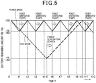
- Fig. 5 is a graph showing changes over time in the battery remaining amount according to mode setting related to operation/stoppage of the engine 41.
- the vertical axis represents the battery remaining amount RB (unit: %), and the horizontal axis represents the time T since the stoppage of the engine. (Refer to Figs. 1 and 2 for the reference signs in the following description.)
- the ECU 65 executes a power mode and an eco mode as operation/stop setting modes of the engine 41.
- the power mode is a mode of the engine 41 for travelling with an increased output of the electric motor 43 during vehicle travel, and as the power consumed by battery 58 is large, the battery 58 is frequently charged by the power generator 48.
- the eco mode is a mode of the engine 41 for travelling with a reduced output of the electric motor 43 during vehicle travel, and as the power consumed by the battery 58 is small, the battery 58 is charged by the power generator 48 at a longer time interval than that of the power mode.
- the battery remaining amount rp is 80%.
- This 80% is defined as a lower battery remaining amount threshold value (a first set value) for starting power generation in the power mode.
- the catalytic device 87 is heated by the heating device 88. Since the time during which the engine is stopped is short and the decrease in the catalyst temperature is small, power consumption in the heating device 88 can be suppressed.
- the battery remaining amount re is 30%. This 30% is defined as a lower battery remaining amount threshold value for starting power generation in the eco mode.
- the battery remaining amount RB after a predetermined time elapse during the stoppage of the engine is predicted, and the catalytic device 87 is heated in preparation of raising the catalyst temperature to the catalytic active temperature by the time at which power generation is started.
- the heating device 88 is operated only for a certain period of time before power generation, power consumption in the heating device 88 can be suppressed.
- the prediction curves of the catalyst temperature are used, a measurement sensor is obviated, which allows the catalyst temperature to be obtained quickly and the cost to be suppressed.
- the motorcycle 10 includes the engine 41, the power generator 48, the battery 58, the electric motor 43, the rear wheel 16 as a drive wheel, the catalytic device 87, and the heating device 88.
- the power generator 48 is driven by the engine 41.
- the battery 58 stores electric power generated by the power generator 48.
- the electric motor 43 is operated by the electric power of the battery 58.
- the rear wheel 16 is driven by the electric motor 43.
- the catalytic device 87 purifies exhaust gas discharged from the engine 41.
- the heating device 88 heats the catalytic device 87.
- the ECU 65 calculates the predicted remaining amount of the battery 58 after a predetermined time elapse based on the remaining amount of the battery 58 and the amount to be decreased per unit time from the remaining amount of the battery 58 so as to heat the catalytic device 87 by means of the heating device 88 when the predicted remaining amount has reached the battery remaining amount r2 as a predetermined value, or when the time t1, which is a predicted time for the predicted remaining amount reaches the battery remaining amount r2, is reached.
- the temperature setting of the catalytic device 87 which is a preparation for power generation, can be performed in time by predicting the remaining amount of the battery 58 after a predetermined time elapse or the time at which the battery remaining amount reaches this battery remaining amount.
- the power mode in which the remaining amount of the battery 58 for starting power generation of the power generator 48 is the battery remaining amount rp as the first set value and the eco mode in which the remaining amount of the battery 58 for starting power generation of the power generator 48 is the battery remaining amount re as the second set value that is lower than the first set value rp are provided so as to heat the catalytic device 87 in the eco mode.
- Fig. 6 is a flowchart showing engine restart restriction according to a bank angle of a vehicle body of the motorcycle 10. (Refer to Figs. 1 and 2 for reference signs in the description below.)
- a left-right inclination angle of the vehicle body that is, a bank angle is measured by a bank angle sensor provided on the vehicle body of the motorcycle 10 (step ST11).
- the ECU 65 determines whether the measured bank angle is larger than a predetermined value (step ST12).
- step ST12, NO If the bank angle is smaller than or equal to the predetermined value (step ST12, NO), restart of the engine 41 is not restricted when the engine 41 is stopped (step ST13). Even if the engine 41 is restarted, the start of the engine 41 has little influence on a behavior of the vehicle body.
- step ST12 When the bank angle is larger than the predetermined value (step ST12, YES), restart of the engine 41 is restricted (step ST14). If the engine 41 is started, the behavior of the vehicle body of the motorcycle 10 may increase.
- the present invention is not limited to the case in which it is applied to the motorcycle 10, and can also be applied to saddle-riding type vehicles including those other than the motorcycle 10.
- the saddle-riding type vehicles include the whole vehicles in which an occupant rides by straddling the vehicle body thereof, and include not only motorcycles (including bicycles with motors) but also three-wheeled vehicles and four-wheeled vehicles classified as ATVs (All Terrain Vehicles). Further, the present invention may be applied to vehicles other than saddle-riding type vehicles.
Landscapes
- Engineering & Computer Science (AREA)
- Chemical & Material Sciences (AREA)
- Mechanical Engineering (AREA)
- Combustion & Propulsion (AREA)
- Transportation (AREA)
- General Engineering & Computer Science (AREA)
- Power Engineering (AREA)
- Chemical Kinetics & Catalysis (AREA)
- Toxicology (AREA)
- Health & Medical Sciences (AREA)
- Automation & Control Theory (AREA)
- Materials Engineering (AREA)
- Life Sciences & Earth Sciences (AREA)
- Sustainable Development (AREA)
- Sustainable Energy (AREA)
- Exhaust Gas After Treatment (AREA)
- Hybrid Electric Vehicles (AREA)
- Control Of Vehicle Engines Or Engines For Specific Uses (AREA)
- Exhaust Gas Treatment By Means Of Catalyst (AREA)
Abstract
Description
- The present invention relates to a motorcycle.
- Conventionally, there is known a motorcycle in which a catalytic device provided therein is heated with an electric heater (see, for example, Patent Literature 1).
- [Patent Literature 1]
Japanese Patent Laid-Open No.2017-52500 - In Patent Literature 1, it requires a long time to heat when a small electric heater is used. Therefore, a case is assumed in which a temperature of a catalytic device has not reached a catalytic active temperature by the time at which it is desired to start power generation, making it impossible to prepare for power generation.
- An object of the present invention is to provide a motorcycle with which the temperature setting of a catalytic device, which is a preparation for power generation, can be performed in time.
- The present specification includes all the contents of Japanese Patent Application No.
2018-061586 filed on March 28, 2018 - The present invention is a motorcycle that includes an engine (41), a power generator (48) driven by the engine (41), a battery (58) for storing electric power generated by the power generator (48), an electric motor (43) operated by the electric power of the battery (58), a drive wheel (16) driven by the electric motor (43), and a catalytic device (87) for purifying exhaust gas discharged from the engine (41), in which a heating device (88) for heating the catalytic device (87) is provided, a predicted remaining amount of the battery (58) after a predetermined time elapse is calculated based on a remaining amount of the battery (58) and an amount to be decreased per unit time from the remaining amount of the battery (58), and the catalytic device (87) is heated by means of the heating device (88) when the predicted remaining amount has reached a predetermined value.
- In the invention described above, the predetermined time may vary depending on a temperature of the catalytic device (87).
- Further, in the invention described above, the temperature of the catalytic device (87) may be calculated from a prediction curve.
- Further, in the invention described above, a power mode in which the remaining amount of the battery (58) for starting power generation of the power generator (48) is a first set value rp and an eco mode in which the remaining amount of the battery (58) for starting power generation of the power generator (48) is a second set value re that is lower than the first set value rp may be provided, and in the eco mode, the catalytic device (87) is heated.
- The present invention is a motorcycle that includes an engine (41), a power generator (48) driven by the engine (41), a battery (58) for storing electric power generated by the power generator (48), an electric motor (43) operated by the electric power of the battery (58), a drive wheel (16) driven by the electric motor (43), and a catalytic device (87) for purifying exhaust gas discharged from the engine (41), in which a heating device (88) for heating the catalytic device (87) is provided, a power mode in which the remaining amount of the battery (58) for starting power generation of the power generator (48) is a first set value rp and an eco mode in which the remaining amount of the battery (58) for starting power generation of the power generator (48) is a second set value re that is lower than the first set value rp are provided, and in the power mode, the catalytic device (87) is heated after the engine (41) has stopped.
- Since the present invention includes the heating device for heating the catalytic device and calculates the predicted remaining amount of the battery after a predetermined time elapse based on the remaining amount of the battery and the amount to be decreased per unit time from the remaining amount of the battery so as to heat the catalytic device by means of the heating device when the predicted remaining amount has reached a predetermined value, the temperature setting of the catalytic device, which is a preparation for power generation, can be performed in time by predicting the remaining amount of the battery after a predetermined time elapse.
- In the invention described above, since the predetermined time varies depending on a temperature of the catalytic device, a preparation for power generation can be made in time according to the change in the temperature of the catalytic device.
- Further, in the invention described above, since the temperature of the catalytic device is calculated from a prediction curve, the temperature of the catalytic device can be obtained quickly by creating a prediction curve in advance, and cost can also be reduced by omitting a temperature sensor.
- Further, in the invention described above, since the power mode in which the remaining amount of the battery for starting power generation of the power generator is the first set value rp and the eco mode in which the remaining amount of the battery for starting power generation of the power generator is the second set value re that is lower than the first set value rp are provided so as to heat the catalytic device in the eco mode, it is possible to meet a wide range of requests from a driver by providing different battery remaining amount modes. Further, in the eco mode, since it is only necessary to heat the catalytic device in time for power generation, power consumption of the heating device can be suppressed.
- The present invention includes the heating device that heats the catalytic device, in which the power mode in which the remaining amount of the battery for starting power generation of the power generator is the first set value rp and the eco mode in which the remaining amount of the battery for starting power generation of the power generator is the second set value re that is lower than the first set value rp are provided, and in the power mode, the temperature of the catalytic device does not easily decrease as the catalytic device is heated after the engine is stopped, so that heating time can be shortened and power consumption of the heating device can be suppressed due to the heating time reduction.
-
- [
Figure 1] Figure 1 is a left side view showing a motorcycle according to an embodiment of the present invention. - [
Figure 2] Figure 2 is a right side view showing a power unit. - [
Figure 3] Figure 3 is a graph showing changes over time in a battery remaining amount and a catalyst temperature after an engine is stopped during vehicle travel. - [
Figure 4] Figure 4 is a flowchart showing a method in which the engine is operated during vehicle travel. - [
Figure 5] Figure 5 is a graph showing changes over time in the battery remaining amount according to mode setting related to operation/stoppage of the engine. - [
Figure 6] Figure 6 is a flowchart showing engine restart restriction according to a bank angle of a vehicle body of the motorcycle. - Hereinafter, an embodiment of the present invention will be described with reference to the drawings. Note that in the description, descriptions of directions such as front and back, right and left, and up and down are the same as directions with respect to a vehicle body unless otherwise specified. Further, in each figure, a reference sign FR indicates a front of the vehicle body, a reference sign UP indicates an upper side of the vehicle body, and a reference sign LH indicates a left side of the vehicle body.
-
Fig. 1 is a left side view showing amotorcycle 10 according to an embodiment of the present invention. - The
motorcycle 10 includes abody frame 11 serving as a skeleton, afront wheel 13 supported on a front end portion of thebody frame 11 via afront fork 12, and arear wheel 16 supported on a lower portion of thebody frame 11 via apower unit 14. - The
motorcycle 10 is a saddle-riding type vehicle of a scooter type in which an occupant sits by straddling aseat 17 disposed above thepower unit 14 and therear wheel 16, and includes avehicle body frame 11 and avehicle body cover 20 that covers the periphery of thevehicle body frame 11. - The
body frame 11 includes ahead pipe 21, adown frame 22, a pair of left and right underframes 23, a pair of left and rightrear frames 24, and a pair of left andright step frames 26. - The
head pipe 21 is provided at a front end portion of thevehicle body frame 11. Thedown frame 22 extends downward from thehead pipe 21. The left and right underframes 23 extend rearward from the left and right sides of a lower portion of thedown frame 22, respectively. The left and rightrear frames 24 extend rearward and obliquely upward from rear ends of the left and right underframes 23, respectively. The left andright step frames 26 are connected to thedown frame 22 and the left and right underframes 23, respectively. - The
front fork 12 has ahandle 31 attached to an upper portion of thefront fork 12, and supports thefront wheel 13 at a lower end portion of thefront fork 12 via anaxle 32. - The
power unit 14 is supported by a pair of left andright pivot plates 35 respectively attached to the left and right underframes 23 and the left and rightrear frames 24 via alink mechanism 36 so as to be swingable up and down. A vehicle bodyside connecting portion 14a is provided at a lower portion of thepower unit 14, and the vehicle bodyside connecting portion 14a is connected to thelink mechanism 36. - The
power unit 14 includes anengine 41 provided at a front portion of thepower unit 14, anelectric motor 43 attached to a rear portion of acrankcase 42 of theengine 41, and anoutput shaft 44 connected to theelectric motor 43 via a speed reduction mechanism (not shown). Areference sign 43a denotes a rotating shaft of theelectric motor 43. - The
engine 41 is a four-cycle engine, and includes thecrankcase 42 and acylinder portion 46 that protrudes forward from a front end portion of thecrankcase 42. - The
crankcase 42 accommodates acrankshaft 47 extending in a direction of a vehicle width and apower generator 48 provided around thecrankshaft 47. Thecylinder portion 46 includes acylinder head 51, and thecylinder head 51 includes anintake device 52 connected to an upper portion of thecylinder head 51 and anexhaust device 53 connected to a lower portion of thecylinder head 51. Theintake device 52 includes anair cleaner 55 attached to an upper portion of thepower unit 14. - The
rear wheel 16 is attached to theoutput shaft 44. Therear wheel 16 is driven by theelectric motor 43. - The
power generator 48 includes a stator (not shown) attached to thecrankcase 42 and a rotor (not shown) attached to thecrankshaft 47 and disposed inside the stator, and the rotor rotates together with thecrankshaft 47 to generate electric power. - A
rear cushion unit 57 is passed between a rear end portion of thepower unit 14 and a rear portion of one of the left and right rear frames 24 (the left side rear frame 24). - A
battery 58 is disposed between the left and right underframes 23 and between the left andright step frames 26. Thebattery 58 stores electric power generated by thepower generator 48. Theelectric motor 43 is operated by the electric power stored in thebattery 58, and therear wheel 16 that is a drive wheel is driven by theelectric motor 43. Thebattery 58 is provided with a remaining amount meter (not shown) that measures a remaining amount of stored electric power (amount of stored power). - A
storage box 61 and afuel tank 62 provided behind thestorage box 61 are attached to the left and rightrear frames 24. Thestorage box 61 and thefuel tank 62 are disposed below theseat 17. - A
stand 64 is attached to a lower portion of thecrankcase 42. - An ECU (Engine Control Unit) 65 that controls operation of the
engine 41 is provided at a rear portion of thehead pipe 21. - The
vehicle body cover 20 includes afront cover 71, a pair of left and right leg shields 72, a pair of left and right floor steps 73, a pair of left and right side skirts 74, a pair of left and right body covers 76, and ahandle cover 77. - The
front cover 71 covers a front of thefront fork 12. The left and right leg shields 72 are connected to both side edges of thefront cover 71 and cover legs of a driver seated on theseat 17 from the front. The left and right floor steps 73 extend rearward from lower end portions of the left and right leg shields 72 and serve as a footrest for the driver. The left and right side skirts 74 extend downward from both side edges of the left and right floor steps 73, respectively. The left and right body covers 76 cover lower portions of both side portions of theseat 17. Thehandle cover 77 covers a central portion of thehandle 31. - The
battery 58 is disposed below the left and right floor steps 73. Thebattery 58 is covered with the vehicle body cover 20 including the left and right floor steps 73, the left and right side skirts 74, and the like. - The
front wheel 13 is covered with afront fender 81 from above, and therear wheel 16 is covered with arear fender 82 from above. -
Fig. 2 is a right side view showing thepower unit 14. - The
crankcase 42 of thepower unit 14 includes a crankcasemain body 42a provided on the side of theengine 41, and arear extension portion 42b extending rearward from the crankcasemain body 42a. Therear extension portion 42b is provided with theelectric motor 43, the speed reduction mechanism (not shown), and theoutput shaft 44. - The
exhaust device 53 includes anexhaust pipe 85 extending downward and rearward from thecylinder head 51, amuffler 86 connected to a rear end portion of theexhaust pipe 85, and acatalytic device 87 provided midway of the exhaust pipe 85 (specifically, at a position near the cylinder head 51), and aheating device 88 capable of heating thecatalytic device 87. - The
catalytic device 87 purifies unpurified components such as a hydrocarbon (HC), a carbon monoxide (CO), a nitrogen oxide (NOx), and the like contained in exhaust gas flowing in theexhaust pipe 85 by removing them with a catalyst. - The
heating device 88 is formed of an electric heater disposed so as to surround thecatalytic device 87, and raises the temperature of the catalyst included in thecatalytic device 87 to a temperature at which the catalyst is activated (a catalytic active temperature). In this regard, note that the temperature of the catalytic device 87 (the temperature of the outer surface) is regarded as the temperature of the catalyst in thecatalytic device 87. - The
exhaust pipe 85 extends back and forth on a side of a lower portion of the crankcase 42 (specifically, the crankcasemain body 42a). Themuffler 86 is disposed on a side of the crankcase 42 (specifically, therear extension portion 42b) and theelectric motor 43. The rear wheel 16 (seeFig. 1 ) is disposed between therear extension portion 42b and themuffler 86. - In
Figs. 1 and2 , themotorcycle 10 is a series hybrid vehicle in which thepower generator 48 is driven by theengine 41, and electric power generated by thepower generator 48 is stored in thebattery 58, and the rear wheel is driven by theelectric motor 43 that operates with the electric power of thebattery 58. - As described above, by arranging the
engine 41 and theelectric motor 43 that are two drive sources in thesame crankcase 42, it is possible to reduce the number of parts and also to reduce a weight, as compared with the case in which theengine 41 and theelectric motor 43 are arranged separately. -
Fig. 3 is a graph showing changes over time in the battery remaining amount and the catalyst temperature after the engine is stopped during vehicle travel. - The vertical axis represents a battery remaining amount RB (%) and a catalyst temperature TC, and the horizontal axis represents a time T after the engine is stopped. (Refer to
Figs. 1 and2 for the reference signs in the following description.) - From the time T = 0 to t1, the battery remaining amount RB is a value actually measured by the remaining amount meter, and the battery remaining amount RB from the time T = t1 to t2 is estimated by using this actual measurement value.
- The catalyst temperature TC is a predicted value based on prediction curves created based on actual measurement data, and from the time T = 0 to t1, a portion of a curve A for predicting a temperature decrease of the
catalytic device 87 due to natural cooling is used, and from time T = t1 to t2, a portion of a curve B for predicting a temperature rise of thecatalytic device 87 due to heating by means of theheating device 88 is used. - First, the battery remaining amount RB and the catalyst temperature TC during the time T = 0 to t1 will be described.
- After the
engine 41 stops at the time T = 0, the battery remaining amount RB gradually decreases from RB = r3 due to power consumption by theelectric motor 43. - When the battery remaining amount RB reaches r2 at the time T = t1, the
heating device 88 is energized and heating of thecatalytic device 87 by means of theheating device 88 is started. - Further, for example, when the
engine 41 is stopped at the time T = 0 in a state in which the catalyst temperature TC is Tc2 (catalytic active temperature), the catalyst temperature TC decreases as the time elapses from the TC = Tc2. At the time T = t1, the catalyst temperature TC is Tc1. - Next, the battery remaining amount RB and the catalyst temperature TC during the time T = t1 to t2 will be described. At the time T = t2 after a predetermined time ts has elapsed from the time T = t1, energization to the
heating device 88 is stopped, and heating of thecatalytic device 87 ends. This heating is a preparation before power generation (which will be described in detail later). - Also, during the time T = t1 to t2, the battery remaining amount RB gradually decreases from r2 due to power consumption by the
electric motor 43 and theheating device 88, and at the time T = t2, the battery remaining amount RB reaches r1. The battery remaining amount r1 is, for example, 30%, and is a battery remaining amount threshold value in an eco mode of theengine 41 that will be described in detail later. - At the time T = t2, power generation by the
power generator 48 is started and generated electric power is stored in thebattery 58, thereby gradually increasing the battery remaining amount RB from the time T = t2 onwards. - At a predetermined time ts from the time T = t1 to T = t2 described above, the battery remaining amount RB is predicted based on a battery remaining amount r3 at the time T = 0 and an amount to be decreased Δr from the battery remaining amount RB per unit time Δt from the time T = 0 to t1.
- During the time T = t1 to t2, the catalyst temperature TC rises from Tc1 to the catalytic active temperature Tc2 by heating the
catalytic device 87 by means of theheating device 88, and a preparation before power generation is completed. That is, if theengine 41 is started and thepower generator 48 is driven, it is possible to suppress discharge of unpurified components in exhaust gas of theengine 41. - The time T = t2 described above is obtained from the actual measurement value of the battery remaining amount RB from the time T = 0 onwards, and the time t1 is obtained from the fact that (1) a temperature change ΔTC (= Tc2 - Tc1) at the time (t1-0 = t1) in the prediction curve A is equal to (2) a temperature change ΔTC at the time (t2 - t1) in the prediction curve B.
- The above two prediction curves A and B are obtained in advance, so that it is not necessary to measure the temperature of the
catalytic device 87 directly with a thermometer or the like. - Since the catalyst temperature TC is affected by an atmospheric temperature, a vehicle speed, and the like, if a change over time in the catalyst temperature TC is obtained for each of several atmospheric temperatures and several vehicle speeds in the above two prediction curves A and B, an accuracy in predicting the catalyst temperature TC can be further increased.
- As shown in
Figs. 2 and3 described above, the predetermined time ts varies depending on a temperature of thecatalytic device 87. For example, inFig. 3 , if the catalyst temperature TC is lower, the predetermined time ts until the catalyst temperature TC rises to the catalytic active temperature becomes longer, and if the catalyst temperature TC is higher, the predetermined time ts until the catalyst temperature TC rises to the catalytic active temperature becomes shorter. - According to this configuration, a preparation for power generation can be made in time corresponding to the change in the temperature of the
catalytic device 87. - Further, since the temperature of the
catalytic device 87 is calculated from the prediction curves A and B, the temperature of thecatalytic device 87 can be obtained quickly by creating the prediction curves A and B in advance, and cost can also be reduced by omitting a temperature sensor. -
Fig. 4 is a flowchart showing a method in which theengine 41 is operated during vehicle travel. (Refer toFigs. 1 and2 for the reference signs in the following description.) - Operation of the
engine 41 is started (step ST01). Thereby, thepower generator 48 is driven by theengine 41 to generate electric power, and the generated electric power is stored in thebattery 58. - Next, the
ECU 65 determines whether the battery remaining amount is larger than an upper battery remaining amount threshold value TR (step ST02). The battery remaining amount threshold value TR is, for example, 95 to 100%. - If the battery remaining amount is less than or equal to the battery remaining amount threshold value TR (step ST02, NO), the engine operation is continued.
- If the battery remaining amount is larger than the battery remaining amount threshold value TR (step ST02, YES), the
engine 41 is stopped (step ST03). During the stoppage of theengine 41, the temperature of thecatalytic device 87 gradually decreases, and the catalytic active performance gradually deteriorates. - Next, the
ECU 65 determines whether there is a catalyst early activation request (step ST04). When power generation is necessary, there is a catalyst early activation request. - If there is no catalyst early activation request (step ST04, NO), the engine stoppage is continued.
- If there is a catalyst early activation request (step ST04, YES), the
catalytic device 87 is heated by means of the heating device 88 (step ST05). With this heating, power generation is prepared. - Next, the
ECU 65 determines whether the catalyst temperature is higher than or equal to a catalyst temperature threshold value (catalytic active temperature) TT (step ST06). - If the catalyst temperature is lower than the catalyst temperature threshold value TT (step ST06, NO), heating of the
catalytic device 87 is continued. - If the catalyst temperature is higher than or equal to the catalyst temperature threshold value TT (step ST06, YES), heating of the
catalytic device 87 is stopped and an operation of theengine 41 is started (step ST07). Thereby, power generation is performed. - As described above, heating of the
catalytic device 87 in step ST05 is performed so that the catalyst temperature reaches the catalytic active temperature by the time at which the engine is operated again. Thereby, when power generation by means of theengine 41 is resumed, the catalyst purification performance of thecatalytic device 87 can be improved, and the discharge of unpurified components in exhaust gas can be suppressed. -
Fig. 5 is a graph showing changes over time in the battery remaining amount according to mode setting related to operation/stoppage of theengine 41. - The vertical axis represents the battery remaining amount RB (unit: %), and the horizontal axis represents the time T since the stoppage of the engine. (Refer to
Figs. 1 and2 for the reference signs in the following description.) - The
ECU 65 executes a power mode and an eco mode as operation/stop setting modes of theengine 41. - The power mode is a mode of the
engine 41 for travelling with an increased output of theelectric motor 43 during vehicle travel, and as the power consumed bybattery 58 is large, thebattery 58 is frequently charged by thepower generator 48. - The eco mode is a mode of the
engine 41 for travelling with a reduced output of theelectric motor 43 during vehicle travel, and as the power consumed by thebattery 58 is small, thebattery 58 is charged by thepower generator 48 at a longer time interval than that of the power mode. - In a power mode diagram line in the graph, the
engine 41 is stopped during vehicle travel at the time T = 0. If the battery remaining amount RB is assumed to be 100% (full charge) at the time T = 0, the battery remaining amount RB decreases with time from 100%, and at the time T = t1, the battery remaining amount RB reaches rp. - For example, the battery remaining amount rp is 80%. This 80% is defined as a lower battery remaining amount threshold value (a first set value) for starting power generation in the power mode. The
engine 41 is started at the time T = t1, and power generation by thepower generator 48 is started. Thereby, the battery remaining amount RB gradually increases, and reaches the battery remaining amount RB = 100% again at the time T = t2. At this point of time, theengine 41 is stopped, and the power generation by thepower generator 48 is temporarily ended. From the time T = t2 onwards, the above processing is repeated. While the engine is stopped in the power mode, thecatalytic device 87 is heated by theheating device 88. Since the time during which the engine is stopped is short and the decrease in the catalyst temperature is small, power consumption in theheating device 88 can be suppressed. - In the eco-mode diagram line in the graph, when the
engine 41 is stopped during vehicle travel at the time T = 0 and the battery remaining amount RB = 100%, the battery remaining amount RB gradually decreases, and at the time T = t5, the battery remaining amount RB reaches re. - For example, the battery remaining amount re is 30%. This 30% is defined as a lower battery remaining amount threshold value for starting power generation in the eco mode. The
engine 41 is started at the time T = t5, and power generation by thepower generator 48 is started. Thereby, the battery remaining amount RB gradually increases, and reaches the battery remaining amount RB = 100% again at the time T = t10. At this point of time, theengine 41 is stopped, and the power generation by thepower generator 48 is temporarily ended. From the time T = t10 onwards, the above processing is repeated. While the engine is stopped in the eco mode, as shown inFig. 3 , the battery remaining amount RB after a predetermined time elapse during the stoppage of the engine is predicted, and thecatalytic device 87 is heated in preparation of raising the catalyst temperature to the catalytic active temperature by the time at which power generation is started. In this way, in the eco mode, since theheating device 88 is operated only for a certain period of time before power generation, power consumption in theheating device 88 can be suppressed. Further, since the prediction curves of the catalyst temperature are used, a measurement sensor is obviated, which allows the catalyst temperature to be obtained quickly and the cost to be suppressed. - As shown in
Figs. 1 ,2 , and3 , themotorcycle 10 includes theengine 41, thepower generator 48, thebattery 58, theelectric motor 43, therear wheel 16 as a drive wheel, thecatalytic device 87, and theheating device 88. - The
power generator 48 is driven by theengine 41. Thebattery 58 stores electric power generated by thepower generator 48. Theelectric motor 43 is operated by the electric power of thebattery 58. Therear wheel 16 is driven by theelectric motor 43. Thecatalytic device 87 purifies exhaust gas discharged from theengine 41. Theheating device 88 heats thecatalytic device 87. - In the
motorcycle 10, theECU 65 calculates the predicted remaining amount of thebattery 58 after a predetermined time elapse based on the remaining amount of thebattery 58 and the amount to be decreased per unit time from the remaining amount of thebattery 58 so as to heat thecatalytic device 87 by means of theheating device 88 when the predicted remaining amount has reached the battery remaining amount r2 as a predetermined value, or when the time t1, which is a predicted time for the predicted remaining amount reaches the battery remaining amount r2, is reached. - According to this configuration, the temperature setting of the
catalytic device 87, which is a preparation for power generation, can be performed in time by predicting the remaining amount of thebattery 58 after a predetermined time elapse or the time at which the battery remaining amount reaches this battery remaining amount. - Further, as shown in
Figs. 1 to 3 andFig. 5 , the power mode in which the remaining amount of thebattery 58 for starting power generation of thepower generator 48 is the battery remaining amount rp as the first set value and the eco mode in which the remaining amount of thebattery 58 for starting power generation of thepower generator 48 is the battery remaining amount re as the second set value that is lower than the first set value rp are provided so as to heat thecatalytic device 87 in the eco mode. - According to this configuration, it is possible to meet a wide variety of requests from a driver by providing different battery remaining amount modes. Further, in the eco mode, since it is only necessary to heat the
catalytic device 87 in time for power generation, power consumption of theheating device 88 can be suppressed. - In addition, as shown in
Figs. 1 ,2 and5 , in the power mode, since thecatalytic device 87 is heated after theengine 41 is stopped, the temperature of thecatalytic device 87 does not easily decrease, so that the heating time can be shortened. Further, as the heating time is shortened, power consumption of theheating device 88 can be suppressed. -
Fig. 6 is a flowchart showing engine restart restriction according to a bank angle of a vehicle body of themotorcycle 10. (Refer toFigs. 1 and2 for reference signs in the description below.) - While the
motorcycle 10 is travelling, a left-right inclination angle of the vehicle body, that is, a bank angle is measured by a bank angle sensor provided on the vehicle body of the motorcycle 10 (step ST11). - The
ECU 65 determines whether the measured bank angle is larger than a predetermined value (step ST12). - If the bank angle is smaller than or equal to the predetermined value (step ST12, NO), restart of the
engine 41 is not restricted when theengine 41 is stopped (step ST13). Even if theengine 41 is restarted, the start of theengine 41 has little influence on a behavior of the vehicle body. - When the bank angle is larger than the predetermined value (step ST12, YES), restart of the
engine 41 is restricted (step ST14). If theengine 41 is started, the behavior of the vehicle body of themotorcycle 10 may increase. - The embodiment described above represents only an aspect of the present invention, and can be arbitrarily modified and applied without departing from the gist of the present invention.
- The present invention is not limited to the case in which it is applied to the
motorcycle 10, and can also be applied to saddle-riding type vehicles including those other than themotorcycle 10. Note that the saddle-riding type vehicles include the whole vehicles in which an occupant rides by straddling the vehicle body thereof, and include not only motorcycles (including bicycles with motors) but also three-wheeled vehicles and four-wheeled vehicles classified as ATVs (All Terrain Vehicles). Further, the present invention may be applied to vehicles other than saddle-riding type vehicles. -
- 10
- Motorcycle
- 16
- Rear wheel (drive wheel)
- 41
- Engine
- 43
- Electric motor
- 48
- Power generator
- 58
- Battery
- 87
- Catalytic device
- 88
- Heating device
- re
- Battery remaining amount (second set value)
- rp
- Battery remaining amount (first set value)
Claims (5)
- A motorcycle comprising:an engine (41);a power generator (48) driven by the engine (41);a battery (58) for storing electric power generated by the power generator (48);an electric motor (43) operated by the electric power of the battery (58);a drive wheel (16) driven by the electric motor (43); anda catalytic device (87) for purifying exhaust gas discharged from the engine (41), wherein:a heating device (88) for heating the catalytic device (87) is provided;a predicted remaining amount of the battery (58) after a predetermined time elapse is calculated based on a remaining amount of the battery (58) and an amount to be decreased per unit time from the remaining amount of the battery (58); andthe catalytic device (87) is heated by means of the heating device (88) when the predicted remaining amount has reached a predetermined value.
- The motorcycle according to Claim 1, wherein the predetermined time varies depending on a temperature of the catalytic device (87).
- The motorcycle according to Claim 2, wherein the temperature of the catalytic device (87) is calculated from a prediction curve.
- The motorcycle according to any one of Claims 1 to 3, wherein
a power mode in which the remaining amount of the battery (58) for starting power generation of the power generator (48) is a first set value rp and an eco mode in which the remaining amount of the battery (58) for starting power generation of the power generator (48) is a second set value re that is lower than the first set value rp are provided, and
in the eco mode, the catalytic device (87) is heated. - A motorcycle comprising:an engine (41);a power generator (48) driven by the engine (41);a battery (58) for storing electric power generated by the power generator (48);an electric motor (43) operated by the electric power of the battery (58);a drive wheel (16) driven by the electric motor (43); anda catalytic device (87) for purifying exhaust gas discharged from the engine (41), wherein:a heating device (88) for heating the catalytic device (87) is provided;a power mode in which a remaining amount of the battery (58) for starting power generation of the power generator (48) is a first set value rp and an eco mode in which the remaining amount of the battery (58) for starting power generation of the power generator (48) is a second set value re that is lower than the first set value rp are provided; andin the power mode, the catalytic device (87) is heated after the engine (41) has stopped.
Applications Claiming Priority (2)
| Application Number | Priority Date | Filing Date | Title |
|---|---|---|---|
| JP2018061586 | 2018-03-28 | ||
| PCT/JP2018/046932 WO2019187409A1 (en) | 2018-03-28 | 2018-12-20 | Motorcycle |
Publications (3)
| Publication Number | Publication Date |
|---|---|
| EP3779134A1 true EP3779134A1 (en) | 2021-02-17 |
| EP3779134A4 EP3779134A4 (en) | 2021-03-10 |
| EP3779134B1 EP3779134B1 (en) | 2022-11-16 |
Family
ID=68061121
Family Applications (1)
| Application Number | Title | Priority Date | Filing Date |
|---|---|---|---|
| EP18912002.5A Active EP3779134B1 (en) | 2018-03-28 | 2018-12-20 | Motorcycle |
Country Status (4)
| Country | Link |
|---|---|
| EP (1) | EP3779134B1 (en) |
| JP (1) | JP6936387B2 (en) |
| CN (1) | CN111868359B (en) |
| WO (1) | WO2019187409A1 (en) |
Families Citing this family (1)
| Publication number | Priority date | Publication date | Assignee | Title |
|---|---|---|---|---|
| CN112627973B (en) * | 2021-01-11 | 2022-07-12 | 重庆宗申发动机制造有限公司 | Range extender for motorcycle |
Family Cites Families (17)
| Publication number | Priority date | Publication date | Assignee | Title |
|---|---|---|---|---|
| US5390493A (en) * | 1992-01-30 | 1995-02-21 | Hitachi, Ltd. | Apparatus for controlling the electric heating of catalyst |
| US5163290A (en) * | 1992-03-11 | 1992-11-17 | Texaco Inc. | Ignition system battery for preheating of automotive catalytic converter |
| JPH0771236A (en) * | 1993-09-02 | 1995-03-14 | Mitsubishi Motors Corp | Electric vehicle with electrically heated catalytic converter |
| JP2587202B2 (en) * | 1994-08-22 | 1997-03-05 | 本田技研工業株式会社 | Power generation control device for hybrid vehicle |
| JPH09250333A (en) * | 1996-03-12 | 1997-09-22 | Nissan Motor Co Ltd | Catalyst warm-up device for internal combustion engine |
| JP3575184B2 (en) * | 1996-09-13 | 2004-10-13 | トヨタ自動車株式会社 | Hybrid vehicle |
| JPH10176561A (en) * | 1996-12-16 | 1998-06-30 | Rongu Well Japan Kk | Hybrid light vehicle |
| JP3573206B2 (en) * | 2002-03-12 | 2004-10-06 | トヨタ自動車株式会社 | Vehicle control device |
| JP2005143169A (en) * | 2003-11-05 | 2005-06-02 | Yamaha Motor Co Ltd | Electric vehicle |
| JP2006174543A (en) * | 2004-12-13 | 2006-06-29 | Honda Motor Co Ltd | Regenerative power control device for hybrid vehicle |
| JP2010023758A (en) * | 2008-07-23 | 2010-02-04 | Toyota Motor Corp | Control device for hybrid vehicle |
| WO2010100748A1 (en) * | 2009-03-06 | 2010-09-10 | トヨタ自動車株式会社 | Hybrid vehicle control device and control method |
| WO2012164715A1 (en) * | 2011-06-02 | 2012-12-06 | トヨタ自動車株式会社 | Vehicle control apparatus, and vehicle control method |
| JP5929699B2 (en) * | 2012-10-18 | 2016-06-08 | トヨタ自動車株式会社 | Control device for hybrid vehicle |
| JP6331749B2 (en) * | 2014-06-23 | 2018-05-30 | 日産自動車株式会社 | Control device for hybrid vehicle |
| JP6319241B2 (en) | 2015-09-11 | 2018-05-09 | マツダ株式会社 | Automobile with generator drive engine |
| JP6855740B2 (en) | 2016-10-11 | 2021-04-07 | 株式会社三洋物産 | Game machine |
-
2018
- 2018-12-20 EP EP18912002.5A patent/EP3779134B1/en active Active
- 2018-12-20 WO PCT/JP2018/046932 patent/WO2019187409A1/en not_active Ceased
- 2018-12-20 JP JP2020509646A patent/JP6936387B2/en not_active Expired - Fee Related
- 2018-12-20 CN CN201880091472.9A patent/CN111868359B/en active Active
Also Published As
| Publication number | Publication date |
|---|---|
| CN111868359A (en) | 2020-10-30 |
| EP3779134B1 (en) | 2022-11-16 |
| EP3779134A4 (en) | 2021-03-10 |
| WO2019187409A1 (en) | 2019-10-03 |
| JP6936387B2 (en) | 2021-09-15 |
| JPWO2019187409A1 (en) | 2021-02-12 |
| CN111868359B (en) | 2021-11-23 |
Similar Documents
| Publication | Publication Date | Title |
|---|---|---|
| JP6319241B2 (en) | Automobile with generator drive engine | |
| EP3236035B1 (en) | Straddled vehicle | |
| US20180156097A1 (en) | Vehicle and control method for vehicle | |
| US10837550B2 (en) | Straddled vehicle | |
| JP5644124B2 (en) | Exhaust gas sensor mounting structure for motorcycles | |
| US20200263591A1 (en) | Method and apparatus for controlling exhaust gas purification system for vehicle | |
| JP2014047762A (en) | Two-wheeled motor vehicle | |
| JP2010125906A (en) | Controller for vehicle | |
| JP3575184B2 (en) | Hybrid vehicle | |
| EP3779134B1 (en) | Motorcycle | |
| JP2008064068A (en) | Motorcycle | |
| WO2014083796A1 (en) | Hybrid vehicle control device | |
| JP2006174543A (en) | Regenerative power control device for hybrid vehicle | |
| EP3415731B1 (en) | Saddle-type vehicle | |
| JP2014065469A (en) | Battery arrangement structure for hybrid vehicle | |
| JP4039572B2 (en) | Hybrid electric vehicle | |
| EP3252288A1 (en) | Engine unit | |
| JP2013203092A (en) | Motorcycle | |
| JP2017150310A (en) | Engine unit and ride type vehicle | |
| JP3942774B2 (en) | Series hybrid electric motorcycle | |
| JP2017150308A (en) | Engine units and vehicles | |
| JP6232952B2 (en) | Electric assist type turbo device for motorcycle, engine equipped with the same, and motorcycle | |
| JP7071190B2 (en) | How to drive motorcycles and motorcycle engines | |
| JP5200801B2 (en) | Control device for hybrid vehicle | |
| WO2023127076A1 (en) | Saddled vehicle |
Legal Events
| Date | Code | Title | Description |
|---|---|---|---|
| STAA | Information on the status of an ep patent application or granted ep patent |
Free format text: STATUS: THE INTERNATIONAL PUBLICATION HAS BEEN MADE |
|
| PUAI | Public reference made under article 153(3) epc to a published international application that has entered the european phase |
Free format text: ORIGINAL CODE: 0009012 |
|
| STAA | Information on the status of an ep patent application or granted ep patent |
Free format text: STATUS: REQUEST FOR EXAMINATION WAS MADE |
|
| 17P | Request for examination filed |
Effective date: 20200818 |
|
| AK | Designated contracting states |
Kind code of ref document: A1 Designated state(s): AL AT BE BG CH CY CZ DE DK EE ES FI FR GB GR HR HU IE IS IT LI LT LU LV MC MK MT NL NO PL PT RO RS SE SI SK SM TR |
|
| AX | Request for extension of the european patent |
Extension state: BA ME |
|
| A4 | Supplementary search report drawn up and despatched |
Effective date: 20210209 |
|
| RIC1 | Information provided on ipc code assigned before grant |
Ipc: B60L 3/00 20190101ALI20210203BHEP Ipc: F01N 3/20 20060101AFI20210203BHEP Ipc: B60K 6/46 20071001ALI20210203BHEP Ipc: B62K 11/10 20060101ALI20210203BHEP Ipc: B62M 7/02 20060101ALI20210203BHEP Ipc: B60W 20/00 20160101ALI20210203BHEP Ipc: B60L 50/15 20190101ALI20210203BHEP Ipc: B60W 10/26 20060101ALI20210203BHEP |
|
| DAV | Request for validation of the european patent (deleted) | ||
| DAX | Request for extension of the european patent (deleted) | ||
| STAA | Information on the status of an ep patent application or granted ep patent |
Free format text: STATUS: EXAMINATION IS IN PROGRESS |
|
| 17Q | First examination report despatched |
Effective date: 20210920 |
|
| GRAP | Despatch of communication of intention to grant a patent |
Free format text: ORIGINAL CODE: EPIDOSNIGR1 |
|
| STAA | Information on the status of an ep patent application or granted ep patent |
Free format text: STATUS: GRANT OF PATENT IS INTENDED |
|
| INTG | Intention to grant announced |
Effective date: 20220609 |
|
| GRAS | Grant fee paid |
Free format text: ORIGINAL CODE: EPIDOSNIGR3 |
|
| GRAA | (expected) grant |
Free format text: ORIGINAL CODE: 0009210 |
|
| STAA | Information on the status of an ep patent application or granted ep patent |
Free format text: STATUS: THE PATENT HAS BEEN GRANTED |
|
| AK | Designated contracting states |
Kind code of ref document: B1 Designated state(s): AL AT BE BG CH CY CZ DE DK EE ES FI FR GB GR HR HU IE IS IT LI LT LU LV MC MK MT NL NO PL PT RO RS SE SI SK SM TR |
|
| REG | Reference to a national code |
Ref country code: GB Ref legal event code: FG4D |
|
| REG | Reference to a national code |
Ref country code: CH Ref legal event code: EP |
|
| REG | Reference to a national code |
Ref country code: IE Ref legal event code: FG4D |
|
| REG | Reference to a national code |
Ref country code: DE Ref legal event code: R096 Ref document number: 602018043261 Country of ref document: DE |
|
| REG | Reference to a national code |
Ref country code: AT Ref legal event code: REF Ref document number: 1531895 Country of ref document: AT Kind code of ref document: T Effective date: 20221215 |
|
| REG | Reference to a national code |
Ref country code: LT Ref legal event code: MG9D |
|
| REG | Reference to a national code |
Ref country code: NL Ref legal event code: MP Effective date: 20221116 |
|
| REG | Reference to a national code |
Ref country code: AT Ref legal event code: MK05 Ref document number: 1531895 Country of ref document: AT Kind code of ref document: T Effective date: 20221116 |
|
| PG25 | Lapsed in a contracting state [announced via postgrant information from national office to epo] |
Ref country code: SE Free format text: LAPSE BECAUSE OF FAILURE TO SUBMIT A TRANSLATION OF THE DESCRIPTION OR TO PAY THE FEE WITHIN THE PRESCRIBED TIME-LIMIT Effective date: 20221116 Ref country code: PT Free format text: LAPSE BECAUSE OF FAILURE TO SUBMIT A TRANSLATION OF THE DESCRIPTION OR TO PAY THE FEE WITHIN THE PRESCRIBED TIME-LIMIT Effective date: 20230316 Ref country code: NO Free format text: LAPSE BECAUSE OF FAILURE TO SUBMIT A TRANSLATION OF THE DESCRIPTION OR TO PAY THE FEE WITHIN THE PRESCRIBED TIME-LIMIT Effective date: 20230216 Ref country code: LT Free format text: LAPSE BECAUSE OF FAILURE TO SUBMIT A TRANSLATION OF THE DESCRIPTION OR TO PAY THE FEE WITHIN THE PRESCRIBED TIME-LIMIT Effective date: 20221116 Ref country code: FI Free format text: LAPSE BECAUSE OF FAILURE TO SUBMIT A TRANSLATION OF THE DESCRIPTION OR TO PAY THE FEE WITHIN THE PRESCRIBED TIME-LIMIT Effective date: 20221116 Ref country code: ES Free format text: LAPSE BECAUSE OF FAILURE TO SUBMIT A TRANSLATION OF THE DESCRIPTION OR TO PAY THE FEE WITHIN THE PRESCRIBED TIME-LIMIT Effective date: 20221116 Ref country code: AT Free format text: LAPSE BECAUSE OF FAILURE TO SUBMIT A TRANSLATION OF THE DESCRIPTION OR TO PAY THE FEE WITHIN THE PRESCRIBED TIME-LIMIT Effective date: 20221116 |
|
| PG25 | Lapsed in a contracting state [announced via postgrant information from national office to epo] |
Ref country code: RS Free format text: LAPSE BECAUSE OF FAILURE TO SUBMIT A TRANSLATION OF THE DESCRIPTION OR TO PAY THE FEE WITHIN THE PRESCRIBED TIME-LIMIT Effective date: 20221116 Ref country code: PL Free format text: LAPSE BECAUSE OF FAILURE TO SUBMIT A TRANSLATION OF THE DESCRIPTION OR TO PAY THE FEE WITHIN THE PRESCRIBED TIME-LIMIT Effective date: 20221116 Ref country code: LV Free format text: LAPSE BECAUSE OF FAILURE TO SUBMIT A TRANSLATION OF THE DESCRIPTION OR TO PAY THE FEE WITHIN THE PRESCRIBED TIME-LIMIT Effective date: 20221116 Ref country code: IS Free format text: LAPSE BECAUSE OF FAILURE TO SUBMIT A TRANSLATION OF THE DESCRIPTION OR TO PAY THE FEE WITHIN THE PRESCRIBED TIME-LIMIT Effective date: 20230316 Ref country code: HR Free format text: LAPSE BECAUSE OF FAILURE TO SUBMIT A TRANSLATION OF THE DESCRIPTION OR TO PAY THE FEE WITHIN THE PRESCRIBED TIME-LIMIT Effective date: 20221116 Ref country code: GR Free format text: LAPSE BECAUSE OF FAILURE TO SUBMIT A TRANSLATION OF THE DESCRIPTION OR TO PAY THE FEE WITHIN THE PRESCRIBED TIME-LIMIT Effective date: 20230217 |
|
| PG25 | Lapsed in a contracting state [announced via postgrant information from national office to epo] |
Ref country code: NL Free format text: LAPSE BECAUSE OF FAILURE TO SUBMIT A TRANSLATION OF THE DESCRIPTION OR TO PAY THE FEE WITHIN THE PRESCRIBED TIME-LIMIT Effective date: 20221116 |
|
| REG | Reference to a national code |
Ref country code: DE Ref legal event code: R119 Ref document number: 602018043261 Country of ref document: DE |
|
| PG25 | Lapsed in a contracting state [announced via postgrant information from national office to epo] |
Ref country code: SM Free format text: LAPSE BECAUSE OF FAILURE TO SUBMIT A TRANSLATION OF THE DESCRIPTION OR TO PAY THE FEE WITHIN THE PRESCRIBED TIME-LIMIT Effective date: 20221116 Ref country code: RO Free format text: LAPSE BECAUSE OF FAILURE TO SUBMIT A TRANSLATION OF THE DESCRIPTION OR TO PAY THE FEE WITHIN THE PRESCRIBED TIME-LIMIT Effective date: 20221116 Ref country code: EE Free format text: LAPSE BECAUSE OF FAILURE TO SUBMIT A TRANSLATION OF THE DESCRIPTION OR TO PAY THE FEE WITHIN THE PRESCRIBED TIME-LIMIT Effective date: 20221116 Ref country code: DK Free format text: LAPSE BECAUSE OF FAILURE TO SUBMIT A TRANSLATION OF THE DESCRIPTION OR TO PAY THE FEE WITHIN THE PRESCRIBED TIME-LIMIT Effective date: 20221116 Ref country code: CZ Free format text: LAPSE BECAUSE OF FAILURE TO SUBMIT A TRANSLATION OF THE DESCRIPTION OR TO PAY THE FEE WITHIN THE PRESCRIBED TIME-LIMIT Effective date: 20221116 |
|
| REG | Reference to a national code |
Ref country code: CH Ref legal event code: PL |
|
| REG | Reference to a national code |
Ref country code: BE Ref legal event code: MM Effective date: 20221231 |
|
| PG25 | Lapsed in a contracting state [announced via postgrant information from national office to epo] |
Ref country code: SK Free format text: LAPSE BECAUSE OF FAILURE TO SUBMIT A TRANSLATION OF THE DESCRIPTION OR TO PAY THE FEE WITHIN THE PRESCRIBED TIME-LIMIT Effective date: 20221116 Ref country code: LU Free format text: LAPSE BECAUSE OF NON-PAYMENT OF DUE FEES Effective date: 20221220 Ref country code: AL Free format text: LAPSE BECAUSE OF FAILURE TO SUBMIT A TRANSLATION OF THE DESCRIPTION OR TO PAY THE FEE WITHIN THE PRESCRIBED TIME-LIMIT Effective date: 20221116 |
|
| PLBE | No opposition filed within time limit |
Free format text: ORIGINAL CODE: 0009261 |
|
| STAA | Information on the status of an ep patent application or granted ep patent |
Free format text: STATUS: NO OPPOSITION FILED WITHIN TIME LIMIT |
|
| 26N | No opposition filed |
Effective date: 20230817 |
|
| GBPC | Gb: european patent ceased through non-payment of renewal fee |
Effective date: 20230216 |
|
| PG25 | Lapsed in a contracting state [announced via postgrant information from national office to epo] |
Ref country code: LI Free format text: LAPSE BECAUSE OF NON-PAYMENT OF DUE FEES Effective date: 20221231 Ref country code: IE Free format text: LAPSE BECAUSE OF NON-PAYMENT OF DUE FEES Effective date: 20221220 Ref country code: DE Free format text: LAPSE BECAUSE OF NON-PAYMENT OF DUE FEES Effective date: 20230701 Ref country code: CH Free format text: LAPSE BECAUSE OF NON-PAYMENT OF DUE FEES Effective date: 20221231 |
|
| PG25 | Lapsed in a contracting state [announced via postgrant information from national office to epo] |
Ref country code: SI Free format text: LAPSE BECAUSE OF FAILURE TO SUBMIT A TRANSLATION OF THE DESCRIPTION OR TO PAY THE FEE WITHIN THE PRESCRIBED TIME-LIMIT Effective date: 20221116 Ref country code: FR Free format text: LAPSE BECAUSE OF NON-PAYMENT OF DUE FEES Effective date: 20230116 Ref country code: BE Free format text: LAPSE BECAUSE OF NON-PAYMENT OF DUE FEES Effective date: 20221231 |
|
| PG25 | Lapsed in a contracting state [announced via postgrant information from national office to epo] |
Ref country code: GB Free format text: LAPSE BECAUSE OF NON-PAYMENT OF DUE FEES Effective date: 20230216 |
|
| PG25 | Lapsed in a contracting state [announced via postgrant information from national office to epo] |
Ref country code: GB Free format text: LAPSE BECAUSE OF NON-PAYMENT OF DUE FEES Effective date: 20230216 |
|
| PG25 | Lapsed in a contracting state [announced via postgrant information from national office to epo] |
Ref country code: CY Free format text: LAPSE BECAUSE OF FAILURE TO SUBMIT A TRANSLATION OF THE DESCRIPTION OR TO PAY THE FEE WITHIN THE PRESCRIBED TIME-LIMIT Effective date: 20221116 |
|
| PG25 | Lapsed in a contracting state [announced via postgrant information from national office to epo] |
Ref country code: MK Free format text: LAPSE BECAUSE OF FAILURE TO SUBMIT A TRANSLATION OF THE DESCRIPTION OR TO PAY THE FEE WITHIN THE PRESCRIBED TIME-LIMIT Effective date: 20221116 Ref country code: HU Free format text: LAPSE BECAUSE OF FAILURE TO SUBMIT A TRANSLATION OF THE DESCRIPTION OR TO PAY THE FEE WITHIN THE PRESCRIBED TIME-LIMIT; INVALID AB INITIO Effective date: 20181220 |
|
| PG25 | Lapsed in a contracting state [announced via postgrant information from national office to epo] |
Ref country code: MC Free format text: LAPSE BECAUSE OF FAILURE TO SUBMIT A TRANSLATION OF THE DESCRIPTION OR TO PAY THE FEE WITHIN THE PRESCRIBED TIME-LIMIT Effective date: 20221116 |
|
| PG25 | Lapsed in a contracting state [announced via postgrant information from national office to epo] |
Ref country code: MC Free format text: LAPSE BECAUSE OF FAILURE TO SUBMIT A TRANSLATION OF THE DESCRIPTION OR TO PAY THE FEE WITHIN THE PRESCRIBED TIME-LIMIT Effective date: 20221116 |
|
| PG25 | Lapsed in a contracting state [announced via postgrant information from national office to epo] |
Ref country code: BG Free format text: LAPSE BECAUSE OF FAILURE TO SUBMIT A TRANSLATION OF THE DESCRIPTION OR TO PAY THE FEE WITHIN THE PRESCRIBED TIME-LIMIT Effective date: 20221116 |
|
| PG25 | Lapsed in a contracting state [announced via postgrant information from national office to epo] |
Ref country code: MT Free format text: LAPSE BECAUSE OF FAILURE TO SUBMIT A TRANSLATION OF THE DESCRIPTION OR TO PAY THE FEE WITHIN THE PRESCRIBED TIME-LIMIT Effective date: 20221116 |
|
| PG25 | Lapsed in a contracting state [announced via postgrant information from national office to epo] |
Ref country code: TR Free format text: LAPSE BECAUSE OF FAILURE TO SUBMIT A TRANSLATION OF THE DESCRIPTION OR TO PAY THE FEE WITHIN THE PRESCRIBED TIME-LIMIT Effective date: 20221116 |
|
| PGFP | Annual fee paid to national office [announced via postgrant information from national office to epo] |
Ref country code: IT Payment date: 20251119 Year of fee payment: 8 |