EP3779092A1 - Skylight window with a crane fastener and method for installing a skylight window - Google Patents
Skylight window with a crane fastener and method for installing a skylight window Download PDFInfo
- Publication number
- EP3779092A1 EP3779092A1 EP20155250.2A EP20155250A EP3779092A1 EP 3779092 A1 EP3779092 A1 EP 3779092A1 EP 20155250 A EP20155250 A EP 20155250A EP 3779092 A1 EP3779092 A1 EP 3779092A1
- Authority
- EP
- European Patent Office
- Prior art keywords
- window
- recess
- frame
- skylight window
- igu
- Prior art date
- Legal status (The legal status is an assumption and is not a legal conclusion. Google has not performed a legal analysis and makes no representation as to the accuracy of the status listed.)
- Withdrawn
Links
Images

Classifications
-
- E—FIXED CONSTRUCTIONS
- E04—BUILDING
- E04D—ROOF COVERINGS; SKY-LIGHTS; GUTTERS; ROOF-WORKING TOOLS
- E04D13/00—Special arrangements or devices in connection with roof coverings; Protection against birds; Roof drainage ; Sky-lights
- E04D13/03—Sky-lights; Domes; Ventilating sky-lights
- E04D13/0305—Supports or connecting means for sky-lights of flat or domed shape
-
- E—FIXED CONSTRUCTIONS
- E04—BUILDING
- E04D—ROOF COVERINGS; SKY-LIGHTS; GUTTERS; ROOF-WORKING TOOLS
- E04D13/00—Special arrangements or devices in connection with roof coverings; Protection against birds; Roof drainage ; Sky-lights
- E04D13/03—Sky-lights; Domes; Ventilating sky-lights
- E04D13/0305—Supports or connecting means for sky-lights of flat or domed shape
- E04D13/031—Supports or connecting means for sky-lights of flat or domed shape characterised by a frame for connection to an inclined roof
-
- E—FIXED CONSTRUCTIONS
- E04—BUILDING
- E04F—FINISHING WORK ON BUILDINGS, e.g. STAIRS, FLOORS
- E04F21/00—Implements for finishing work on buildings
- E04F21/0007—Implements for finishing work on buildings for mounting doors, windows or frames; their fitting
- E04F21/0015—Implements for finishing work on buildings for mounting doors, windows or frames; their fitting for mounting frames
Definitions
- a skylight window for installing on or in a roof structure of a building a system for installing a skylight window and a method for installing a skylight window onto a roof structure of a building.
- the present invention relates to a skylight window for installing on or in a roof structure of a building, the skylight window comprising a window frame having four frame side members together delimiting a frame opening, and, if the skylight window is openable, a window sash having four sash side members, said window sash being movable in relation to the window frame between an open and a closed position of the skylight window, an Insulating Glazing Unit (IGU) having an interior major surface for facing an interior of a building in an installed position, and if the window is openable in the closed position of the skylight window, said IGU further having an exposed exterior major surface for facing in an exterior direction which is opposite of said interior of said building in said installed position of the skylight window, said IGU covering the frame opening, each frame side members, having an inner surface facing towards the frame opening, and an outer member surface facing away from the frame opening, a first of the frame side members extending in a longitudinal direction along a first peripheral side of the IGU, and a second frame side member extending
- the invention also relates to a system comprising a skylight window, and a method of installing a skylight window onto a roof structure.
- the installation of a skylight window generally comprises transporting the skylight window to the roof, positioning the skylight window in or on the roof at a desired position, wherein the skylight window covers an opening in the roof, and fastening the skylight window to the roof.
- the installation may further comprise the mounting of a roofing felt for weather-proofing the window.
- skylight windows When installing skylight windows, the skylight windows must be brought to the roof construction in which the window is to be installed. This may and have been done by moving and lifting the windows manually.
- skylight windows are fragile and normally quite heavy structures weighing up to and sometimes even more than 100 kg.
- lifting devices such as cranes, hoists or the like, are used to aid in lifting the windows in place on the roof structure or even directly into an opening in the roof structure provided for receiving the window.
- This solution lightens the job of the workers installing skylight windows considerably and is more gentle to both the window and the worker's health.
- a skylight window of the type mentioned in the introduction simplifying the mounting of a skylight window by enabling the skylight windows to be brought to the roof construction in which the window is to be installed in a simple, safe and time efficient manner while complying with security regulations, and while also reducing the risk of damage to the window as well as the roof structure and workers during lifting of the window.
- each of the first frame side member and second frame side member comprises at least one recess, such as a hole or an opening, in the outer member surface, wherein an attachment device is inserted into the at least one recess, the attachment device having an accessible inner geometry, said attachment device being adapted for temporary interlocking with a lifting device.
- a skylight window is provided which also comprises an attachment device inserted into the recess.
- the frame is thus adapted for attachment of a lifting device, wherein a lifting device may be attached to the attachment device in an easy, safe and quick manner.
- the provision of the recess with the inserted attachment device in the frame side members allows for an easy and efficient solution, without imposing additional costs to the user for purchasing extra components for the installation.
- the first and second frame side members each having a recess may allow the lifting device to attach to the attachment devices in the two frame side members, thus ensuring a safe and stable lifting of the skylight window.
- the attachment device being inserted into the recess makes it very simple and for the lifting device to attach and detach from the window. It may further provide for a particularly robust and durable connection with the window when attached thereto, this connection simultaneously being very gentle to the window during lifting thereof. This in turn provides for a solution making it simple and quick to lift a window to a desired place in or on a roof construction and also being sufficiently safe to comply with the relevant security regulations.
- a further advantage of the invention is that the recess may allow for installation of the skylight window by an installer from a position being further away from an opening in the roof structure, which is prepared to receive the skylight window.
- the attachment device may be a fastener, such as a bolt with an exposed shaft, a mounting bracket or other attachment means.
- the attachment device may comprise an inner geometry which is exposed and/or accessible.
- the attachment device may comprise a shaft, such as a leg to be inserted into the recess and a headed projection or protrusion, such as a bolt base.
- the leg of the attachment device may attach to the inner surface of the recess defined in the inward direction. Alternatively, it may attach to another part of the first frame side and/or another element of the window being positioned adjacent to the first or second frame side member. This structure may provide a resilient connection enabling the attachment to the window and the lifting device.
- the attachment device may comprise metal, such as such as stainless steel, or other high strength and solid material.
- the interior direction is defined as being perpendicular to the IGU major surface and opposite the exterior direction. In the installed position of the skylight window, the interior direction is pointing towards an interior of the building and the exterior direction is pointing towards an exterior of the building.
- An inward or inner direction is defined toward the frame opening and perpendicular to the longitudinal direction.
- An outward or outer direction is defined as being opposite the inward direction.
- the term "interior” is used to indicate that something is intended to face the interior of the building in or on which the skylight window is installed.
- the term “exterior” is used to indicate that something is intended to face in a direction opposite to the interior of the building in or on which the skylight window is installed.
- the terms “inner” and “outer” are used to indicate that something is intended for facing in the inward or outward direction, towards or away, respectively, from the frame opening.
- IGU is an abbreviation of "Insulating Glazing Unit” and is a concept well-known to the skilled person.
- the IGU may have multiple layers of glass or glazing, which layers may define a potentially sealed volume or spacing between them, the spacing potentially comprising an inert gas, an aerogel, or a vacuum.
- the IGU may in a conventional manner comprise one, two, three or more layers of glazing, i.e. layers of glass, polycarbonate or the like, or glass panels, which may be positioned at a distance from each other to form one or more spacings or cavities between them. This spacing may be filled with a gas or may hold a vacuum to improve insulation properties of the IGU.
- the exposed interior major surface of the IGU may be a lower major surface of a lowermost of the layers of glazing.
- Sealing and/or supporting members or spacers may be provided at one or more of four peripheral sides of the IGU between the layers of glazing and may form a so-called spacer frame.
- the sealing and/or supporting members may distance adjacent layers of glazing from each other and may together with lateral edges of the layers of glazing form respective side or lateral surfaces of the IGU. These side surfaces may be substantially plane and/or extend substantially in the height dimension as defined herein.
- the skylight window may be openable, the skylight window comprising a window sash having four sash side members, said window sash being movable in relation to the window frame between an open and a closed position of the skylight window.
- the first sash side member has a first leg connected to a supporting section of the first sash side member supporting the IGU, the first leg extending in the longitudinal direction and extending substantially in a height direction substantially perpendicularly to at least one of the major surfaces of the IGU, the first leg having a thickness in a width direction extending perpendicularly to said length and height directions.
- At least a portion of the first leg of the first sash side member may be generally plate-shaped, consisting of one single section of substantially solid material having a said thickness less than 1 cm.
- the first leg having a thickness less than 1 cm may have the advantage of allowing the IGU to extend closer to the frame side members as the thickness of material extending along the peripheral sides of the IGU is reduced. This may have the effect of improving the insulation properties of the skylight as the relative area of the superior insulating IGU is increased compared to other parts of the skylight. Moreover, this will lead to a more light-weight structure that can potentially be easier to manufacture and lead to cost savings with regards to the material use.
- the sash may be made movable in relation to the window frame by the sash being openable toward the exterior of the building, i.e. being rotatable about an axis extending along one of the sash side members.
- the sash moves away from the frame during opening towards the exterior. This is contrary to pivot-hung skylights in which the sash moves both outwards and inwards during opening and employ a different design.
- the sash being openable to the exterior may be achieved by using a rotary hinge positioned at a sash side member and connecting this sash side member with an associated, adjacent frame side member.
- the sash may be parallel-displaceable so that all four sash side members shift upwardly or downwardly between the open and closed positions of the window in which case further or other hinges or the like connect the sash with the frame.
- the skylight window may be openable by a combination of a rotary movement and a shifting movement or other movement paths of the sash in relation to the frame.
- the exposed interior major surface of the IGU may be a lower surface of the IGU and/or may face in a downwards direction towards an interior of the building in an installed position of the skylight window.
- the exterior major surface may be substantially parallel with and/or may have substantially the same or the same shape and size as the interior major surface of the IGU. A distance between the two major surfaces defines a thickness of the IGU, which distance may be measured in the height dimension.
- the IGU may have a rectangular shape and may have further second to fourth peripheral sides that each extends linearly along, potentially along a substantially total extent of, a corresponding respective sash member.
- the peripheral sides may define a shape of the IGU.
- the four frame side members may together form a substantially rectangular shape. Additionally or alternatively, the four sash side members may together form a substantially rectangular shape. A rectangular shape of the four sash side members may be smaller than a rectangular shape of the four frame sash side members, which may allow the sash to be embedded within the frame in the closed position of the skylight window.
- the interior pane may be an interior one of the layers of glazing of the IGU.
- an external surface of the first insulation member facing the IGU may be inclined or stepped in relation to the height direction so that a lower portion of the insulation member is wider than an upper portion of the insulation member.
- the skylight window is non-openable, and, potentially substantially an entire, external surface of the first insulation member facing the IGU may extend substantially in the height direction.
- One or more gaskets or sealing members may be provided between the external surface of the insulation member facing the IGU and the IGU.
- the skylight window further comprises a weather shield attached to the frame or, if the skylight window is openable, to the window sash so as to protect a window portion of the skylight window, the window portion comprising the frame, IGU and, if the skylight window is openable, the window sash.
- the weather shield may be understood as a transparent cover member, preferably a dome of glass or a clear polymer.
- the weather shield may be dome-shaped. In an openable skylight window and during an opening movement, the weather shield may typically follow the movement of the sash.
- the main purpose of the dome or weather shield is to protect the sash and frame from the weather and to avoid accumulation of precipitation and dirt on the IGU.
- the weather shield may be provided as a unitary structure, which is detachably attached to the to the sash.
- the weather shield may be attached detachably to the sash, providing for access to clean the IGU; this may also be of advantage during mounting of the skylight window, e.g. when positioning or attaching the window portion or when attaching roofing felt to cover a potential gap between the frame and the roof structure.
- the weather shield may be mounted on the window portion to protect it from the elements and preventing rain and other downfall from entering into gaps or slots in the roof or the window portion.
- the weather shield may comprise a weather shield pane positioned on an exterior side of the IGU.
- the weather shield may comprise a weather shield pane that may be surrounded by a weather shield skirt that may extend on an outer side of all four sides of the frame, i.e. of the respective frame side members.
- the skirt may be manufactured from or include metal.
- the weather shield pane may curve upwardly in relation to the window portion or the IGU to allow for rain and snow to slide or flow off of the weather shield pane.
- the weather shield pane may be a transparent window pane that may be of glass, tempered glass or hardened glass.
- the weather shield pane may comprise only one single layer of glazing.
- a weather shield may comprise a transparent or translucent weather shield pane or cover member, e.g. a dome of glass or a clear polymer
- the weather shield may be provided without a sealed gas-filled spacing between the weather shield pane and the IGU.
- the weather shield may comprise a weather shield pane that may be surrounded by a weather shield skirt that may extend on an outer side of all four sides of the frame, i.e. of the respective frame side members.
- the skirt may be manufactured from or include metal.
- the weather shield pane may curve upwardly in relation to the window portion or the IGU to allow for rain and snow to slide or flow off of the weather shield pane.
- the weather shield pane may be a transparent window pane that may be of glass or hardened glass.
- the weather shield pane may comprise only one single layer of glazing.
- the weather shield is replaced by a flat window pane, which may be positioned to be substantially parallel to the window portion.
- the sash side members are connected to the exterior major surface of the IGU and extending away from the interior major surface of the IGU, i.e. not extending below the exterior major surface of the IGU in the mounted state. In this way the IGU may be positioned as deep as possible in relation to the roof structure, thereby potentially improving the insulating properties of the window.
- the first sash side member may have a first leg connected to a supporting section of the first sash side member supporting the IGU, the first leg extending in said longitudinal direction and extending substantially in a height direction substantially perpendicularly to at least one of said major surfaces of the IGU.
- the sash side member may further comprise a second leg and possibly further legs in order to allow a more complex structure.
- the second and/or possible further legs may also be substantially plate-shaped.
- the legs form a stepped profile, when the cross-section perpendicular to the longitudinal direction.
- An upper surface of the second leg may be denoted a step surface.
- a step profile may be achieved by making the sash side member with two, three or more legs where each leg is substantially perpendicular to an immediately preceding leg and/or an immediately following leg.
- a stepped configuration of adjacent surfaces of the first sash and frame side members may thus be achieved by means of the stepped profile of the first sash side member as described and an associated stepped profile of the first frame side member according to the present embodiment.
- This stepped configuration may provide a labyrinth like structure of a potential be-tween the sash and frame side member resulting in a less direct path for air, precipitation or dirt to pass between the interior and exterior of the building.
- the stepped profile also provides the possibility of placing sealing elements along the profile such that sealing is facilitated between two parallel surfaces i.e. a surface of the frame side member and a parallel sash side member.
- the sealing between the stepped profile of the sash and frame side member may further be aided by the load transfer of the load exerted by the IGU through the sash.
- insulating sealing members may conveniently be positioned between the first sash and frame side members at respective corners of the stepped configurations, e.g. as described in the above.
- insulating and sealing properties of the skylight window may be further increased.
- Such a step may also be used for supporting a screening device, such as a roller blind.
- each of the first and second frame side members comprises at least two recesses in the outer member surface. This may allow for a stable and secure lifting by the lifting device, wherein the total weight of the skylight window is shared between the two frame side members.
- the first and second frame side members may include exactly two recesses in the outer member surface. This configuration may reduce the installation time, since the lifting device may have to attach to fewer attachment devices and make the whole installation more efficient.
- the first frame side member further comprises a lining panel protrusion located lower than the exposed interior major surface of the IGU in the height direction, wherein the interior pane comprises a side surface extending substantially along the first frame and sash side members, wherein the lining panel protrusion protrudes away from the IGU, the lining panel protrusion comprising a first surface for abutting a surface of reveal panel or lining panel so as to position the reveal panel or lining panel, and wherein, in the closed position of the skylight window, the first surface of the lining panel protrusion in a lateral direction extending along the exposed interior major surface of the IGU is positioned farther away from the side surface of the interior pane than the supporting leg.
- Such protrusion can help an installer install a lining panel at the skylight window by guiding an upper end of the lining panel into contact with a first side of the protrusion, and may further ease the installation by hiding the upper end of said lining panel e.g. if the upper end is not flush with the interior side of the skylight window.
- the lining panel can be used to hide the skylight frame, for viewers, including insulation elements such as an insulting block and can thus, allow for improving the insulating properties of the skylight window as a whole.
- the skylight window may further comprise a second protrusion next to the first protrusion to create a lining panel recess for receiving a lining panel to be installed.
- Said lining panel recess would add to the guidance and ease of installation of the lining panel.
- the skylight window may comprise a removable lining panel protrusion and/or recess.
- the removable lining panel protrusion and/or recess may be separately affixed to the frame and may be a part that is separate from the frame i.e. not an integral part of the frame.
- an outer surface of one or more frame side members may be flat and allow the attachment of a curb flange.
- the curb flange may be a detachably attachable curb flange.
- detachably attachable may be understood as the curb flange being attachable and detachable without causing substantial and/or permanent damage to the curb flange or skylight window.
- each of the first and second frame side members have at least one recess on the exterior half of the outer member surface and at least one recess on the interior half of the outer member surface.
- the exterior half of the outer member surface is to be understood as facing toward the exterior of the building where the skylight window is to be installed, while the interior half of the outer member surface is facing opposite the exterior one. This embodiment allows the weight of the skylight window -that is to be lifted- to be equally divided in two, resulting in a balanced lift of the window.
- the recess is provided with a threaded insert which is connected to the frame side member or to a reinforcement of the frame side member.
- this threaded insert may be understood as the attachment device.
- the threaded insert may be configured to be engaged with the attachment device.
- the reinforcement may be an insert, such as a metal profile or laminated wood profile or fiber reinforced polymer profile, covered by a visible frame exterior, if the frame side member consists of polymer, such as PVC.
- the threaded insert may be a bushing, which is brought into engagement with the inner geometry of the recess.
- the recess is covered by a roof covering, such as a roofing felt in the installed position of the skylight window. This may prevent water from penetrating into the window structure from the recess.
- the recess may be a blind hole.
- the recess may be a through hole extending throughout the width of the frame side member, the width being defined in the inward direction and being perpendicular to the longitudinal direction.
- the recess may comprise a stepped configuration, where a part of the recess has a larger diameter than another part of the recess. The diameter of the recess is to be understood in the exterior direction being perpendicular to the width of the recess.
- the recess may be in the form of a track on the outer member surface of the first frame side member.
- the recess may further comprise one or more holes to receive the attachment device.
- the recess may have a width which is 2/3 of the width of the frame side member.
- the width of the recess may alternatively be 30%, 40%, 50%, 60% or higher than 60% of the width of the frame side member.
- the diameter of the recess may be 1/3, 1/2 or 2/3 of the height of the IGU.
- the diameter of the recess may be larger than 2/3 of the height if the IGU.
- the recess may be positioned in the exterior part of the first frame side member.
- the height of the IGU is defined as the distance between the major surfaces of the IGU (exterior, interior) extending in the exterior direction.
- the window sash side member may comprise a recess in an outer surface, wherein an attachment device is inserted into said recess, said attachment device having an inner geometry for temporary interlocking with a lifting device.
- the window sash may further comprise one or more thermal breaks
- the thermal break may be made from a material of a lower thermal conductivity than other parts of the first sash side member.
- the thermal break may be a joint joining parts of the sash. This may have the advantage of improving the insulation properties of the skylight as a lower thermal conductivity through the supporting section or sash member may be achieved.
- Thermal breaks may also be used for interconnecting the window frame and the sash.
- the thermal break may be substantially made from or comprise a polymer or foam
- IGU is an abbreviation of "Insulating Glazing Unit” and is a concept well-known to the skilled person.
- the IGU may have multiple layers of glass which define a volume comprising an inert gas or aerogels or vacuum.
- the IGU may in a conventional manner comprise one or, preferably two, three or more layers of glazing positioned at a distance from each other to form one or more sealed spacings or cavities between them. This spacing may be filled with an inertgas or may hold a vacuum to improve insulation.
- One or more of the layers of glazing may have a low emissivity coating or coating stack.
- One or more of the layers of glazing may be laminated e.g. the interior layer of glazing.
- One or more of the layers of glazing may be tempered.
- the weather shield pane may be tempered.
- the IGU may be see-through transparent to provide a view out.
- the exposed interior major surface of the IGU may in that case be a lower major surface of a lowermost of the layers of glazing.
- Sealing and/or supporting members may be provided at one or more of four peripheral sides of the IGU between the layers of glazing.
- the sealing and/or supporting members may distance adjacent layers of glazing from each other and may together with lateral edges of the window glazing layers form respective side or lateral surfaces of the IGU. These side surfaces may be substantially plane and extend substantially in the height dimension as defined herein.
- the sash may comprise or substantially consist of metal, such as steel or aluminium and/or polymer fibre-reinforced polymer, PUR, pultruded, glass fibre, aluminium, polyester or composite.
- the skylight window is further comprising a weather shield attached to the frame or, if the skylight window is openable, to the window sash, wherein said weather shield comprises preferably at least one recess, such as a hole or an opening, in an outer shield surface in the outward direction away from the frame opening in the closed position, wherein an attachment device is inserted into said at least one recess(interlocking), said attachment device having an inner geometry for temporary interlocking with a lifting device, and wherein the weather shield preferably covers the recess on the frame side member in an installed position of the weather shield.
- a weather shield attached to the frame or, if the skylight window is openable, to the window sash
- said weather shield comprises preferably at least one recess, such as a hole or an opening, in an outer shield surface in the outward direction away from the frame opening in the closed position, wherein an attachment device is inserted into said at least one recess(interlocking), said attachment device having an inner geometry for temporary interlocking with a lifting
- each of said four frame side members have an outer member surface in the outward direction facing away from the frame opening, each of the frame side members comprising at least one recess, such as a hole or an opening, in the outer member surface, wherein an attachment device is inserted into said at least one recess(interlocking), said attachment device having an inner geometry for temporary interlocking with a lifting device.
- a lifting device such as a craning tool including lifting straps
- a system for installing a skylight window for installing on or in a roof structure of a building comprising the skylight window and further comprising at least two lifting brackets, each of said lifting brackets comprising a leg portion, said leg portion is to be inserted into the recess and a first annular portion connected to the leg portion, said lifting bracket further comprising a second annular portion connected to a second leg portion, said second leg portion is configured to be temporary interlocking with the lifting device, such that the first and second annular portions are connected with each other forming a chain-like structure, such as a swivel eye snap.
- the lifting brackets may be attached to the recess of the first and second frame side member and/or to the recess of the weather shield.
- the lifting brackets may alternatively be lifting straps, loops, cords or barrel bolts.
- the lifting brackets may substantially comprise a high strength material.
- a method for installing a skylight window onto a roof structure of a building comprising a window frame having four frame side members together delimiting a frame opening, and if the skylight window is openable, a window sash having four sash side members, said window sash being movable in relation to the window frame between an open and a closed position of the skylight window, said frame side members and/or sash side members supporting an IGU having multiple layers of glazing, said IGU having an exposed interior major surface for facing an interior of said building in an installed position of the skylight window, the exposed interior major surface being of an interior pane of the IGU, said IGU further having an exterior major surface facing towards an exterior of the skylight window, said IGU covering the frame opening, wherein each frame side members, having an inner surface in an inward direction towards the frame opening, and an outer member surface in an outward direction away from the frame opening, a first of the frame side members extending in a longitudinal direction along a first
- the method further comprises the step of (e) covering the outer member surface comprising the recess with a roof covering, such as a roofing felt.
- the skylight window further comprises a weather shield attached to the frame or, if the skylight window is openable, to a window sash, wherein said weather shield comprises preferably at least one recess, such as a hole or an opening, in an outer shield surface in the outward direction away from the frame opening, wherein an attachment device is inserted into said at least one recess(interlocking), said attachment device having an accessible inner geometry and being adapted for temporary interlocking with a lifting device, and wherein the weather shield preferably covers the recess on the frame side member in an installed position of the weather shield.
- the method of installation of the skylight window further comprises the step of:
- the weather shield may be provided separately from the skylight window.
- the lifting of the skylight window and the lifting of the weather shield may be performed in separate steps to allow for the installation of a roof covering, which may be covering the recess of the frame side member.
- the weather shield may comprise a skirt, said skirt may obstruct the installation of such a roof covering. The lifting of the weather shield may therefore be performed in a subsequent step after the roof covering has been installed onto the skylight window.
- the method may also comprise the step of:
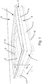
- Fig. 1 shows an embodiment of a skylight window 1 installed in a roof 2 of a building and covering an opening (not shown) in the roof 2.
- the skylight window 1 comprises a weather shield 3 protecting a window portion 4, which includes an IGU 5, a sash 6 supporting the IGU 5, and a frame 7.
- a roofing felt (not shown) may in a conventional manner be positioned to seal between outer surfaces of the frame 7 and of the roof 2. These outer surfaces of the frame 7 are here formed by a curb flange 40 of the frame 7.
- the weather shield 3 may also include a flashing or cladding (not shown).
- the weather shield 3 is attached to the sash 6 so as to protect the window portion 4 of the skylight window 1.
- the weather shield 3 comprises a transparent weather shield pane 8 and a skirt 9, which cover the sash 6 and the IGU 5.
- the skylight window 1 does not include the weather shield 3.
- the slightly curved weather shield pane 8 as seen in Fig. 1 extends over an entire roof opening (not shown), which opening the skylight window 1 is positioned to cover.
- the weather shield pane 8 is surrounded by the weather shield skirt 9, which extends on an outer side of all four sides of the frame 7, i.e. of the four frame side members. No sealed gas-filled spacing is provided between the weather shield pane 8 and the IGU 5; rather, this spacing is ventilated.
- both the entire sash 6 and the entire frame 7 are positioned above an upper roof surface of the roof 2, also denoted the exterior roof surface.
- the skylight window 1 may, however, also be positioned so that a part of the frame 7 and/or the sash 6 are positioned below the exterior roof surface level.
- the flat roof 2 shown in Fig. 1 has a roof inclination of about 0 degrees in relation to horizontal.
- the skylight window may, however, also be installed in an inclined roof having a roof inclination larger than 0 degrees.
- the skylight window 1 comprises a substantially flat weather shield 3 attached to the window sash 6 so as to protect a window portion 4 of the skylight window 1.
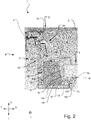
- the skylight window 1 shown in Fig. 2 may be according to the embodiment of Fig. 1 unless otherwise stated in the following.
- the window portion 4 of Fig. 2 comprises a frame 7, IGU 5, and a sash 6.
- the weather shield 3 may alternatively be shaped similarly to the weather shield pane 8 and weather shield 3 shown in Fig. 1 .
- the IGU 5 -shown in a schematic way in this embodiment- has an exposed interior major surface 5b for facing an interior of the building in the closed position of the skylight window 1, the exposed interior major surface being of an interior pane of the IGU 5.
- the interior pane comprises a side surface 5s extending substantially along the first frame side member 10 and first sash side member 14.
- the IGU 5 further has an exterior major surface 5g facing towards an exterior in the closed position of the skylight window 1, wherein the first frame side member 10 has a frame height extending in a height direction shown in Fig. 2 .
- the height direction is parallel to the exterior direction and substantially perpendicular to the major surfaces of the IGU 5 in the closed position of the skylight window 1.
- the first frame side member 10 and the first sash side member 14 extend in a length or longitudinal direction L, also shown in Fig. 2 , along the side surface 5s of the interior pane in the closed position of the IGU 5.
- the first frame side member 10 comprises a load-carrying structure for carrying at least part of both the sash 6 and the IGU 5 in the closed position of the skylight window 1.
- the load-carrying structure has an external surface 10x facing the side surface 5s of the interior pane.
- the first insulation member 81 is provided separately from the first frame side member 10 and is positioned between the external surface 10x and the side surface 5s of the interior pane in the closed position of the skylight window 1.
- the first insulation member 81 extends substantially along an entire length of the first frame side member 10.
- the insulation member 81 comprises a protrusion 87 in a lower part thereof, said protrusion 87 is the IGU 5 and is positioned below a supporting leg 79 of the first sash side member 14.
- a width direction shown in Fig. 2 extends perpendicularly to the longitudinal direction L and to the height direction and is parallel to the inward direction.
- a width in the width direction of the insulation member 81 is larger than a height of the IGU 5.
- the height of the IGU 5 is equal to the distance between the interior 5b and exterior 5g major surfaces of the IGU 5.
- the first insulation member 81 is attached to the first frame side member 10.
- the insulation material of the first insulation member 81 consists of expanded polystyrene.
- the first frame side member 10 further comprises a recess 85, shown in Fig. 2 , which is extending from an outer member surface 10t of the first frame side member 10 in the inward direction towards the IGU.
- the recess 85 is provided so that an attachment device (not shown) may be inserted into the recess 85 to be attached to the first frame side member 10, the attachment device having an inner geometry and is adapted for temporary interlocking with a lifting device (not shown) for lifting the skylight window 1 during or before installation thereof.
- the recess 85 is a blind hole, having a width defined in the inward direction D, said width is substantially 2/3 of the width of the first frame side member 10.
- the recess 85 has a diameter, which is defined in the exterior direction E being perpendicular to the width of the recess, and the diameter of the recess is 1/3 of the height of the IGU.
- the height of the IGU 5 is defined as the distance between the major surfaces of the IGU 5b, 5g extending in the exterior direction E.
- the first frame side member 10 may comprise two recesses 85 in the outer member surface 10t (not shown here).
- the second frame side member 11 which is not shown here, also comprises at least one recess 85.
- the first 10 and second 11 frame side members have at least one recess 85 on the top half of the outer member surface 10t and at least one recess 85 on the bottom half of the outer member surface 10t.
- the recess 85 comprises a threaded insert (not shown) which is connected to to the frame side member 10.
- the recess 85 in the installed position of the skylight window 1, is covered by a roof covering, such as roofing felt (not shown).
- the weather shield 3 preferably comprises a recess 92 (not shown), in an outer shield surface in the outward direction O away from the frame opening, wherein an attachment device is inserted into the recess(interlocking), said attachment device having an inner geometry for temporary interlocking with a lifting device, and wherein the weather shield 3 preferably covers the recess 85 on the frame side member 10 in an installed position of the weather shield 3.
- a sealing element 86 shown in Fig. 2 , is positioned above the insulation member 81 and is attached to the first sash side member 6.
- the sealing element 86 extends between the first sash side member 6 and the insulating member 81 in the shown closed position of the skylight window 1 in order to seal a spacing between these.
- a total sash height HS is about 106% of the total frame height HF and the total height of the interior part HI is about 23% of the total frame height HF.
- a total height of the supporting leg HL is about 0.3% of the total frame height HF.
- a ratio of the total height HL of the supporting leg 79 to the total supporting leg width WL is about 1:5, and a ratio of a total supporting leg width WL to a total sash height HS is about 1:12.
- the first sash side member 14 comprises a first sealing element 14a near the weather shield skirt 9 for sealing against the first frame side member 10 to prevent precipitation or debris such as dust or dirt from entering between the sash 6 and frame 7.
- the first sash side member 14 further comprises a second sealing element 14b located above the insulation member 81 and having the same purpose.
- the IGU 5 and the weather shield 3 are, accordingly, carried directly by the first frame side member 10, i.e. no first sash side member 6 is provided between them.
- Other parts of the embodiment of Fig.3 are identical or similar to the previous embodiments, unless stated otherwise in the following.
- the attachment device 93 is shown inserted into the recess 85 on the first frame side member 10.
- the first insulation member 81 is partly encased in a cover 82 covering parts of surfaces of the insulation member 81 facing away from the first frame side member 10. Such a cover could also be included in the previous embodiments.
- the cover 82 is not part of the load-bearing structure of the first frame side member 10.
- the insulation member 81 of this embodiment further comprises a recess 83 on a side surface 81s of the insulation member 81 facing towards the side surface 5s of the IGU 5, wherein the cover 82 is attached to the recess 83.
- the first insulation member 81 extends substantially from the external surface 10x of the load-carrying structure to the side surface 5s of the interior pane.
- the first frame side member 10 includes a supporting leg 72 positioned in the height direction beneath the internal major surface 5b of the IGU 5.
- a lower part of the insulation member 81 is positioned in an upwardly facing recess 84 of the first frame side member 10, the recess 84 being defined by a side surface 72s of the supporting leg 72, an exterior surface 10f of the first frame side member 10, the exterior surface 10f facing upwardly in a height direction, and the external surface 10x of the first frame side member 10.
- the first insulation member 81 comprises chamfered corners, which facilitate its installation in the skylight window 1 and allow for installation of optional auxiliary wedge parts provided for a smooth transition between the frame 7 and the insulation member 81.
- the recess 85 located on the exterior part of the first frame side member 10 extending from the outer member surface 10t in the inward direction until the inner surface 85i of the recess.
- the recess has extended dimensions, with the diameter of the recess exceeding the height of the IGU.
- the recess is here positioned at close proximity with the weather shield skirt 9.
- the attachment device 93 is inserted into the recess 85.
- it comprises a shaft 100 inserted into the recess and into part of the first frame side member and a projection 99, which has the form of a bolt base.
- the projection 99 is inserted into the recess 85 at 1/3 of the width of the recess 85 from the outer member surface 10t.
- the shaft 100 of the attachment device 93 may attach to the inner surface 85i of the recess 85 defined in the inward direction or to another element of the window 1 being positioned adjacent to the first frame side member 10.
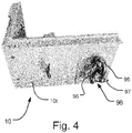
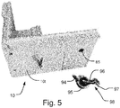
- Figs 4-5 show perspective views of a part of a system comprising a skylight window in an embodiment of the present invention, where a lifting bracket 98 is in an installed position and in an uninstalled position into the recess 85, respectively.
- the system may comprise two lifting brackets 98, each of said lifting brackets 98 comprising a leg portion 94 to be inserted into the recess 85 and a first annular portion 95 connected to the leg portion 94.
- the recess 85 is here in the form of a hole.
- the lifting bracket 98 further comprises a second annular portion 96 connected to a second leg portion 97, the second leg portion 97 being configured to temporary interlock with the lifting device, such that the first 95 and second 96 annular portions are connected with each other forming a chain-like structure, such as a swivel eye snap.
- the lifting bracket 98 comprises the leg portion 94 to be inserted into the recess 85 and the first annular portion 95 connected to the leg portion 94.
- the leg portion 94 may alternatively be connected with the attachment device 93 (not shown), which may be a metal insert.
- the lifting bracket 98 may attach to the recess of the frame 85 or to the recess of the weather shield 92.
- the method comprises the steps of: (a) attaching a lifting device to the attachment device 93, such that a temporary interlocking is established between the lifting device and the attachment device 93, (b) lifting and/or moving the window 1 to a desired place on or in the roof structure 2, using the lifting device, by applying a lifting force to the skylight window 1, (c) arranging the window 1 on the desired place on or in the roof structure 2 by reducing the lifting force from the lifting device to the skylight window 1, (d) releasing the lifting device from the attachment device 93.
- the method may further comprise the step of (e) covering the recess 85 with roof covering, such as a roofing felt.
- the skylight window 1 further comprises the weather shield 3 attached to the frame 7 or, if the skylight window is openable, to the window sash 6, the weather shield 3 comprises preferably at least one recess 92, such as a hole or an opening, in an outer shield surface in the outward direction O away from the frame opening, wherein the attachment device 93 is inserted into the at least one recess 93 and wherein the weather shield 3 preferably covers the recess 85 on the frame side member 10 in an installed position of the weather shield 3.
- the weather shield 3 comprises preferably at least one recess 92, such as a hole or an opening, in an outer shield surface in the outward direction O away from the frame opening, wherein the attachment device 93 is inserted into the at least one recess 93 and wherein the weather shield 3 preferably covers the recess 85 on the frame side member 10 in an installed position of the weather shield 3.
- the method of installation further comprises the step of (f) attaching a lifting device to the attachment device 93 inserted in the recess 92 of the weather shield 3, such that a temporary interlocking is established between the lifting device and the attachment device 93, (g) lifting and/or moving the weather shield 3 to a desired place on or in the roof structure 2, using the lifting device, by applying a lifting force and/or a directional force to the weather shield 3, (h) arranging the weather shield 3 on the desired place on or in the roof structure 2 by reducing the lifting force from the lifting device to the weather shield 3, (i) releasing the lifting device from the attachment device 93.
- the lifting of the skylight window 1 may also comprise the (j) attachment of a lifting bracket 98 to the attachment device 93.
- the lifting bracket 98 may comprise the first leg portion 94 configured for temporary interlocking with the attachment device 93 on the recess 92 on the weather shield, and the second leg portion 97.
- the method may further comprise the (k) attachment of the lifting device (not shown) to the lifting bracket 98 by temporary interlocking the lifting device to the second leg portion 97 of the lifting bracket 98.
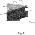
- Fig. 6 shows an embodiment of a part of the skylight window 1, where the recess 85 is in the form of a track, further comprising a hole and the skylight window comprises the attachment device 93, which comprises a projection 99.
- the attachment device 93 is inserted into the recess and attached onto the first frame side member 10.
Landscapes
- Engineering & Computer Science (AREA)
- Architecture (AREA)
- Civil Engineering (AREA)
- Structural Engineering (AREA)
- Wing Frames And Configurations (AREA)
Abstract
Description
- A skylight window for installing on or in a roof structure of a building, a system for installing a skylight window and a method for installing a skylight window onto a roof structure of a building.
- The present invention relates to a skylight window for installing on or in a roof structure of a building, the skylight window comprising a window frame having four frame side members together delimiting a frame opening, and, if the skylight window is openable, a window sash having four sash side members, said window sash being movable in relation to the window frame between an open and a closed position of the skylight window, an Insulating Glazing Unit (IGU) having an interior major surface for facing an interior of a building in an installed position, and if the window is openable in the closed position of the skylight window, said IGU further having an exposed exterior major surface for facing in an exterior direction which is opposite of said interior of said building in said installed position of the skylight window, said IGU covering the frame opening, each frame side members, having an inner surface facing towards the frame opening, and an outer member surface facing away from the frame opening, a first of the frame side members extending in a longitudinal direction along a first peripheral side of the IGU, and a second frame side member extending along an opposite second peripheral side of the IGU parallel to the first frame side member.
- The invention also relates to a system comprising a skylight window, and a method of installing a skylight window onto a roof structure.
- The installation of a skylight window generally comprises transporting the skylight window to the roof, positioning the skylight window in or on the roof at a desired position, wherein the skylight window covers an opening in the roof, and fastening the skylight window to the roof. The installation may further comprise the mounting of a roofing felt for weather-proofing the window.
- When installing skylight windows, the skylight windows must be brought to the roof construction in which the window is to be installed. This may and have been done by moving and lifting the windows manually. However, skylight windows are fragile and normally quite heavy structures weighing up to and sometimes even more than 100 kg.
- Thus, lifting devices, such as cranes, hoists or the like, are used to aid in lifting the windows in place on the roof structure or even directly into an opening in the roof structure provided for receiving the window. This solution lightens the job of the workers installing skylight windows considerably and is more gentle to both the window and the worker's health.
- However, drawbacks still remain. In particular, it is a slow and cumbersome, but nevertheless inevitable, process to ensure that the skylight windows are securely fastened during the lifting process. Inevitable as it enables the lifting process to be completed without putting the workers in danger and while avoiding detrimental effects on the material used, windows and roof structure included, and thus in such a manner that all security regulations are complied with.
- Therefore, it is the object of the invention to provide a skylight window of the type mentioned in the introduction simplifying the mounting of a skylight window by enabling the skylight windows to be brought to the roof construction in which the window is to be installed in a simple, safe and time efficient manner while complying with security regulations, and while also reducing the risk of damage to the window as well as the roof structure and workers during lifting of the window.
- This and further objects are achieved with a skylight window of the kind mentioned in the introduction which is furthermore characterised in that each of the first frame side member and second frame side member comprises at least one recess, such as a hole or an opening, in the outer member surface, wherein an attachment device is inserted into the at least one recess, the attachment device having an accessible inner geometry, said attachment device being adapted for temporary interlocking with a lifting device.
- By providing each of the first and second frame side member with a recess in the outer member surface, a skylight window is provided which also comprises an attachment device inserted into the recess. The frame is thus adapted for attachment of a lifting device, wherein a lifting device may be attached to the attachment device in an easy, safe and quick manner.
- The provision of the recess with the inserted attachment device in the frame side members allows for an easy and efficient solution, without imposing additional costs to the user for purchasing extra components for the installation. The first and second frame side members each having a recess may allow the lifting device to attach to the attachment devices in the two frame side members, thus ensuring a safe and stable lifting of the skylight window.
- The attachment device being inserted into the recess makes it very simple and for the lifting device to attach and detach from the window. It may further provide for a particularly robust and durable connection with the window when attached thereto, this connection simultaneously being very gentle to the window during lifting thereof. This in turn provides for a solution making it simple and quick to lift a window to a desired place in or on a roof construction and also being sufficiently safe to comply with the relevant security regulations.
- A further advantage of the invention is that the recess may allow for installation of the skylight window by an installer from a position being further away from an opening in the roof structure, which is prepared to receive the skylight window.
- The attachment device may be a fastener, such as a bolt with an exposed shaft, a mounting bracket or other attachment means. The attachment device may comprise an inner geometry which is exposed and/or accessible. The attachment device may comprise a shaft, such as a leg to be inserted into the recess and a headed projection or protrusion, such as a bolt base. The leg of the attachment device may attach to the inner surface of the recess defined in the inward direction. Alternatively, it may attach to another part of the first frame side and/or another element of the window being positioned adjacent to the first or second frame side member. This structure may provide a resilient connection enabling the attachment to the window and the lifting device. The attachment device may comprise metal, such as such as stainless steel, or other high strength and solid material.
- The interior direction is defined as being perpendicular to the IGU major surface and opposite the exterior direction. In the installed position of the skylight window, the interior direction is pointing towards an interior of the building and the exterior direction is pointing towards an exterior of the building. An inward or inner direction is defined toward the frame opening and perpendicular to the longitudinal direction. An outward or outer direction is defined as being opposite the inward direction.
- Throughout this text the term "interior" is used to indicate that something is intended to face the interior of the building in or on which the skylight window is installed. The term "exterior" is used to indicate that something is intended to face in a direction opposite to the interior of the building in or on which the skylight window is installed. The terms "inner" and "outer" are used to indicate that something is intended for facing in the inward or outward direction, towards or away, respectively, from the frame opening.
- The term IGU is an abbreviation of "Insulating Glazing Unit" and is a concept well-known to the skilled person.
- The IGU may have multiple layers of glass or glazing, which layers may define a potentially sealed volume or spacing between them, the spacing potentially comprising an inert gas, an aerogel, or a vacuum. The IGU may in a conventional manner comprise one, two, three or more layers of glazing, i.e. layers of glass, polycarbonate or the like, or glass panels, which may be positioned at a distance from each other to form one or more spacings or cavities between them. This spacing may be filled with a gas or may hold a vacuum to improve insulation properties of the IGU. The exposed interior major surface of the IGU may be a lower major surface of a lowermost of the layers of glazing. Sealing and/or supporting members or spacers may be provided at one or more of four peripheral sides of the IGU between the layers of glazing and may form a so-called spacer frame. The sealing and/or supporting members may distance adjacent layers of glazing from each other and may together with lateral edges of the layers of glazing form respective side or lateral surfaces of the IGU. These side surfaces may be substantially plane and/or extend substantially in the height dimension as defined herein.
- In an embodiment, the skylight window may be openable, the skylight window comprising a window sash having four sash side members, said window sash being movable in relation to the window frame between an open and a closed position of the skylight window. The first sash side member has a first leg connected to a supporting section of the first sash side member supporting the IGU, the first leg extending in the longitudinal direction and extending substantially in a height direction substantially perpendicularly to at least one of the major surfaces of the IGU, the first leg having a thickness in a width direction extending perpendicularly to said length and height directions. At least a portion of the first leg of the first sash side member may be generally plate-shaped, consisting of one single section of substantially solid material having a said thickness less than 1 cm. The first leg having a thickness less than 1 cm may have the advantage of allowing the IGU to extend closer to the frame side members as the thickness of material extending along the peripheral sides of the IGU is reduced. This may have the effect of improving the insulation properties of the skylight as the relative area of the superior insulating IGU is increased compared to other parts of the skylight. Moreover, this will lead to a more light-weight structure that can potentially be easier to manufacture and lead to cost savings with regards to the material use.
- The sash may be made movable in relation to the window frame by the sash being openable toward the exterior of the building, i.e. being rotatable about an axis extending along one of the sash side members. By 'openable toward the exterior', it is to be understood that the sash moves away from the frame during opening towards the exterior. This is contrary to pivot-hung skylights in which the sash moves both outwards and inwards during opening and employ a different design. The sash being openable to the exterior may be achieved by using a rotary hinge positioned at a sash side member and connecting this sash side member with an associated, adjacent frame side member. Alternatively or additionally, the sash may be parallel-displaceable so that all four sash side members shift upwardly or downwardly between the open and closed positions of the window in which case further or other hinges or the like connect the sash with the frame. The skylight window may be openable by a combination of a rotary movement and a shifting movement or other movement paths of the sash in relation to the frame.
- The exposed interior major surface of the IGU may be a lower surface of the IGU and/or may face in a downwards direction towards an interior of the building in an installed position of the skylight window.
- The exterior major surface may be substantially parallel with and/or may have substantially the same or the same shape and size as the interior major surface of the IGU. A distance between the two major surfaces defines a thickness of the IGU, which distance may be measured in the height dimension.
- The IGU may have a rectangular shape and may have further second to fourth peripheral sides that each extends linearly along, potentially along a substantially total extent of, a corresponding respective sash member. The peripheral sides may define a shape of the IGU.
- The four frame side members may together form a substantially rectangular shape. Additionally or alternatively, the four sash side members may together form a substantially rectangular shape. A rectangular shape of the four sash side members may be smaller than a rectangular shape of the four frame sash side members, which may allow the sash to be embedded within the frame in the closed position of the skylight window.
- The interior pane may be an interior one of the layers of glazing of the IGU.
- Especially if the skylight window is openable, an external surface of the first insulation member facing the IGU may be inclined or stepped in relation to the height direction so that a lower portion of the insulation member is wider than an upper portion of the insulation member. Especially if the skylight window is non-openable, and, potentially substantially an entire, external surface of the first insulation member facing the IGU may extend substantially in the height direction.
- One or more gaskets or sealing members may be provided between the external surface of the insulation member facing the IGU and the IGU.
- In an embodiment, the skylight window further comprises a weather shield attached to the frame or, if the skylight window is openable, to the window sash so as to protect a window portion of the skylight window, the window portion comprising the frame, IGU and, if the skylight window is openable, the window sash.
- In the following, the weather shield may be understood as a transparent cover member, preferably a dome of glass or a clear polymer.
- The weather shield may be dome-shaped. In an openable skylight window and during an opening movement, the weather shield may typically follow the movement of the sash. The main purpose of the dome or weather shield is to protect the sash and frame from the weather and to avoid accumulation of precipitation and dirt on the IGU.
- The weather shield may be provided as a unitary structure, which is detachably attached to the to the sash. The weather shield may be attached detachably to the sash, providing for access to clean the IGU; this may also be of advantage during mounting of the skylight window, e.g. when positioning or attaching the window portion or when attaching roofing felt to cover a potential gap between the frame and the roof structure.The weather shield may be mounted on the window portion to protect it from the elements and preventing rain and other downfall from entering into gaps or slots in the roof or the window portion. The weather shield may comprise a weather shield pane positioned on an exterior side of the IGU.
- The weather shield may comprise a weather shield pane that may be surrounded by a weather shield skirt that may extend on an outer side of all four sides of the frame, i.e. of the respective frame side members. The skirt may be manufactured from or include metal. The weather shield pane may curve upwardly in relation to the window portion or the IGU to allow for rain and snow to slide or flow off of the weather shield pane. Alternatively or additionally, the weather shield pane may be a transparent window pane that may be of glass, tempered glass or hardened glass. The weather shield pane may comprise only one single layer of glazing.
- A weather shield may comprise a transparent or translucent weather shield pane or cover member, e.g. a dome of glass or a clear polymer
- The weather shield may be provided without a sealed gas-filled spacing between the weather shield pane and the IGU.The weather shield may comprise a weather shield pane that may be surrounded by a weather shield skirt that may extend on an outer side of all four sides of the frame, i.e. of the respective frame side members. The skirt may be manufactured from or include metal. The weather shield pane may curve upwardly in relation to the window portion or the IGU to allow for rain and snow to slide or flow off of the weather shield pane. Alternatively or additionally, the weather shield pane may be a transparent window pane that may be of glass or hardened glass. The weather shield pane may comprise only one single layer of glazing.
- In alternative embodiments, the weather shield is replaced by a flat window pane, which may be positioned to be substantially parallel to the window portion.
- In an embodiment of an openable skylight window, the sash side members are connected to the exterior major surface of the IGU and extending away from the interior major surface of the IGU, i.e. not extending below the exterior major surface of the IGU in the mounted state. In this way the IGU may be positioned as deep as possible in relation to the roof structure, thereby potentially improving the insulating properties of the window.
- The first sash side member may have a first leg connected to a supporting section of the first sash side member supporting the IGU, the first leg extending in said longitudinal direction and extending substantially in a height direction substantially perpendicularly to at least one of said major surfaces of the IGU.
- The sash side member may further comprise a second leg and possibly further legs in order to allow a more complex structure. The second and/or possible further legs may also be substantially plate-shaped.
- In an embodiment, the legs form a stepped profile, when the cross-section perpendicular to the longitudinal direction. An upper surface of the second leg may be denoted a step surface. A step profile may be achieved by making the sash side member with two, three or more legs where each leg is substantially perpendicular to an immediately preceding leg and/or an immediately following leg.
- A stepped configuration of adjacent surfaces of the first sash and frame side members may thus be achieved by means of the stepped profile of the first sash side member as described and an associated stepped profile of the first frame side member according to the present embodiment. This stepped configuration may provide a labyrinth like structure of a potential be-tween the sash and frame side member resulting in a less direct path for air, precipitation or dirt to pass between the interior and exterior of the building. The stepped profile also provides the possibility of placing sealing elements along the profile such that sealing is facilitated between two parallel surfaces i.e. a surface of the frame side member and a parallel sash side member. The sealing between the stepped profile of the sash and frame side member may further be aided by the load transfer of the load exerted by the IGU through the sash. Furthermore, insulating sealing members may conveniently be positioned between the first sash and frame side members at respective corners of the stepped configurations, e.g. as described in the above. Hereby, insulating and sealing properties of the skylight window may be further increased.
- Such a step may also be used for supporting a screening device, such as a roller blind.
- In an embodiment, each of the first and second frame side members comprises at least two recesses in the outer member surface. This may allow for a stable and secure lifting by the lifting device, wherein the total weight of the skylight window is shared between the two frame side members.
- The first and second frame side members may include exactly two recesses in the outer member surface. This configuration may reduce the installation time, since the lifting device may have to attach to fewer attachment devices and make the whole installation more efficient.
- In an embodiment, the first frame side member further comprises a lining panel protrusion located lower than the exposed interior major surface of the IGU in the height direction,
wherein the interior pane comprises a side surface extending substantially along the first frame and sash side members,
wherein the lining panel protrusion protrudes away from the IGU, the lining panel protrusion comprising a first surface for abutting a surface of reveal panel or lining panel so as to position the reveal panel or lining panel, and
wherein, in the closed position of the skylight window, the first surface of the lining panel protrusion in a lateral direction extending along the exposed interior major surface of the IGU is positioned farther away from the side surface of the interior pane than the supporting leg. - Such protrusion can help an installer install a lining panel at the skylight window by guiding an upper end of the lining panel into contact with a first side of the protrusion, and may further ease the installation by hiding the upper end of said lining panel e.g. if the upper end is not flush with the interior side of the skylight window. The lining panel can be used to hide the skylight frame, for viewers, including insulation elements such as an insulting block and can thus, allow for improving the insulating properties of the skylight window as a whole.
- The skylight window may further comprise a second protrusion next to the first protrusion to create a lining panel recess for receiving a lining panel to be installed. Said lining panel recess would add to the guidance and ease of installation of the lining panel.
- The skylight window may comprise a removable lining panel protrusion and/or recess. The removable lining panel protrusion and/or recess may be separately affixed to the frame and may be a part that is separate from the frame i.e. not an integral part of the frame.
- In an embodiment an outer surface of one or more frame side members may be flat and allow the attachment of a curb flange. The curb flange may be a detachably attachable curb flange. The term "detachably attachable" may be understood as the curb flange being attachable and detachable without causing substantial and/or permanent damage to the curb flange or skylight window.
- In an embodiment, each of the first and second frame side members have at least one recess on the exterior half of the outer member surface and at least one recess on the interior half of the outer member surface. Splitting the outer member surface in two substantially equal parts, the exterior half of the outer member surface is to be understood as facing toward the exterior of the building where the skylight window is to be installed, while the interior half of the outer member surface is facing opposite the exterior one. This embodiment allows the weight of the skylight window -that is to be lifted- to be equally divided in two, resulting in a balanced lift of the window.
- In an embodiment, the recess is provided with a threaded insert which is connected to the frame side member or to a reinforcement of the frame side member. In some embodiments, this threaded insert may be understood as the attachment device. Alternatively, the threaded insert may be configured to be engaged with the attachment device. The reinforcement may be an insert, such as a metal profile or laminated wood profile or fiber reinforced polymer profile, covered by a visible frame exterior, if the frame side member consists of polymer, such as PVC. The threaded insert may be a bushing, which is brought into engagement with the inner geometry of the recess.
- In an embodiment, the recess is covered by a roof covering, such as a roofing felt in the installed position of the skylight window. This may prevent water from penetrating into the window structure from the recess.
- The recess may be a blind hole. Alternatively, the recess may be a through hole extending throughout the width of the frame side member, the width being defined in the inward direction and being perpendicular to the longitudinal direction. The recess may comprise a stepped configuration, where a part of the recess has a larger diameter than another part of the recess. The diameter of the recess is to be understood in the exterior direction being perpendicular to the width of the recess.
- The recess may be in the form of a track on the outer member surface of the first frame side member. The recess may further comprise one or more holes to receive the attachment device.
- The recess may have a width which is 2/3 of the width of the frame side member. The width of the recess may alternatively be 30%, 40%, 50%, 60% or higher than 60% of the width of the frame side member. The diameter of the recess may be 1/3, 1/2 or 2/3 of the height of the IGU. The diameter of the recess may be larger than 2/3 of the height if the IGU. The recess may be positioned in the exterior part of the first frame side member. The height of the IGU is defined as the distance between the major surfaces of the IGU (exterior, interior) extending in the exterior direction.
- In an embodiment where the skylight window is openable, the window sash side member may comprise a recess in an outer surface, wherein an attachment device is inserted into said recess, said attachment device having an inner geometry for temporary interlocking with a lifting device.
- The window sash may further comprise one or more thermal breaks The thermal break may be made from a material of a lower thermal conductivity than other parts of the first sash side member. The thermal break may be a joint joining parts of the sash. This may have the advantage of improving the insulation properties of the skylight as a lower thermal conductivity through the supporting section or sash member may be achieved. Thermal breaks may also be used for interconnecting the window frame and the sash. The thermal break may be substantially made from or comprise a polymer or foam
- The term IGU is an abbreviation of "Insulating Glazing Unit" and is a concept well-known to the skilled person.
- The IGU (Insulated Glazing Unit) may have multiple layers of glass which define a volume comprising an inert gas or aerogels or vacuum. The IGU may in a conventional manner comprise one or, preferably two, three or more layers of glazing positioned at a distance from each other to form one or more sealed spacings or cavities between them. This spacing may be filled with an inertgas or may hold a vacuum to improve insulation. One or more of the layers of glazing may have a low emissivity coating or coating stack. One or more of the layers of glazing may be laminated e.g. the interior layer of glazing. One or more of the layers of glazing may be tempered. Similarly, the weather shield pane may be tempered. The IGU may be see-through transparent to provide a view out. The exposed interior major surface of the IGU may in that case be a lower major surface of a lowermost of the layers of glazing. Sealing and/or supporting members may be provided at one or more of four peripheral sides of the IGU between the layers of glazing. The sealing and/or supporting members may distance adjacent layers of glazing from each other and may together with lateral edges of the window glazing layers form respective side or lateral surfaces of the IGU. These side surfaces may be substantially plane and extend substantially in the height dimension as defined herein.
- The sash may comprise or substantially consist of metal, such as steel or aluminium and/or polymer fibre-reinforced polymer, PUR, pultruded, glass fibre, aluminium, polyester or composite.
- In an embodiment, the skylight window is further comprising a weather shield attached to the frame or, if the skylight window is openable, to the window sash, wherein said weather shield comprises preferably at least one recess, such as a hole or an opening, in an outer shield surface in the outward direction away from the frame opening in the closed position, wherein an attachment device is inserted into said at least one recess(interlocking), said attachment device having an inner geometry for temporary interlocking with a lifting device, and wherein the weather shield preferably covers the recess on the frame side member in an installed position of the weather shield.
- In an embodiment, each of said four frame side members have an outer member surface in the outward direction facing away from the frame opening, each of the frame side members comprising at least one recess, such as a hole or an opening, in the outer member surface, wherein an attachment device is inserted into said at least one recess(interlocking), said attachment device having an inner geometry for temporary interlocking with a lifting device. This embodiment may allow a lifting device, such as a craning tool including lifting straps, to attach to the corner joints of all four frame side members, resulting in a stable lift.
- In a second aspect of the invention, a system for installing a skylight window for installing on or in a roof structure of a building, is provided, the system comprising the skylight window and further comprising at least two lifting brackets, each of said lifting brackets comprising a leg portion, said leg portion is to be inserted into the recess and a first annular portion connected to the leg portion, said lifting bracket further comprising a second annular portion connected to a second leg portion, said second leg portion is configured to be temporary interlocking with the lifting device, such that the first and second annular portions are connected with each other forming a chain-like structure, such as a swivel eye snap.
- The lifting brackets may be attached to the recess of the first and second frame side member and/or to the recess of the weather shield.
- The lifting brackets may alternatively be lifting straps, loops, cords or barrel bolts. The lifting brackets may substantially comprise a high strength material.
- In a third aspect of the invention, a method for installing a skylight window onto a roof structure of a building is provided, the skylight window comprising a window frame having four frame side members together delimiting a frame opening, and if the skylight window is openable, a window sash having four sash side members, said window sash being movable in relation to the window frame between an open and a closed position of the skylight window, said frame side members and/or sash side members supporting an IGU having multiple layers of glazing, said IGU having an exposed interior major surface for facing an interior of said building in an installed position of the skylight window, the exposed interior major surface being of an interior pane of the IGU, said IGU further having an exterior major surface facing towards an exterior of the skylight window, said IGU covering the frame opening, wherein each frame side members, having an inner surface in an inward direction towards the frame opening, and an outer member surface in an outward direction away from the frame opening, a first of the frame side members extending in a longitudinal direction along a first peripheral side of the IGU, and a second frame side member extending along an opposite second peripheral side of the IGU parallel to the first frame side member, wherein each of the first frame side member and second frame side member comprises at least one recess, such as a hole or an opening, in the outer member surface, wherein an attachment device is inserted into said at least one recess, said attachment device having an accessible inner geometry and being adapted for temporary interlocking with a lifting device, the method comprising the steps of:
- attaching a lifting device to (at least a part of) the attachment device, such that a temporary interlocking is established between the lifting device and the attachment device,
- lifting and/or moving the window to a desired place on or in the roof structure, using the lifting device, by applying a lifting force to the skylight window,
- arranging the window on the desired place on or in the roof structure by reducing the lifting force from the lifting device to the skylight window,
- releasing the lifting device from the attachment device.
- In another embodiment, the method further comprises the step of (e) covering the outer member surface comprising the recess with a roof covering, such as a roofing felt.
- In an embodiment, the skylight window further comprises a weather shield attached to the frame or, if the skylight window is openable, to a window sash, wherein said weather shield comprises preferably at least one recess, such as a hole or an opening, in an outer shield surface in the outward direction away from the frame opening, wherein an attachment device is inserted into said at least one recess(interlocking), said attachment device having an accessible inner geometry and being adapted for temporary interlocking with a lifting device, and wherein the weather shield preferably covers the recess on the frame side member in an installed position of the weather shield. In this embodiment, the method of installation of the skylight window further comprises the step of:
- attaching the lifting device to the attachment device inserted in the recess of the weather shield, such that a temporary interlocking is established between the lifting device and the attachment device,
- lifting and/or moving the weather shield to a desired place on or in the skylight window, using the lifting device, by applying a lifting force to the weather shield,
- arranging the weather shield on the desired place on or in the skylight window, by reducing the lifting force from the lifting device to the weather shield,
- releasing the lifting device from the attachment device.
- The weather shield may be provided separately from the skylight window. The lifting of the skylight window and the lifting of the weather shield may be performed in separate steps to allow for the installation of a roof covering, which may be covering the recess of the frame side member. The weather shield may comprise a skirt, said skirt may obstruct the installation of such a roof covering. The lifting of the weather shield may therefore be performed in a subsequent step after the roof covering has been installed onto the skylight window.
- The method may also comprise the step of:
- attaching a lifting bracket to the attachment device, said lifting bracket comprising a leg portion, said leg portion is to be inserted into the recess and a first annular portion connected to the leg portion, said lifting bracket further comprising a second annular portion connected to a second leg portion, such that the first and second annular portions are connected with each other forming a chain-like structure, such as a swivel eye snap,
- attaching the lifting device to the lifting bracket by temporary interlocking the lifting device to the second leg portion of the lifting bracket.
-
-
Figure 1 shows a perspective view of a skylight window installed on a roof of a building according to an embodiment of the present invention, -
Figure 2 shows a cross-sectional view of a part of a skylight window according to an embodiment of the present invention, -
Figure 3 shows a cross-sectional view of a part of a skylight window according to another embodiment of the present invention, -
Figure 4 shows a perspective view of a part of a skylight window, where an attachment device has been inserted to the recess of the frame side member, -
Figure 5 shows a perspective view of a part of a skylight window according to the embodiment ofFig. 4 , where the attachment device is not inserted into the recess, -
Fig. 6 shows a perspective view of a part of a skylight window according to an embodiment of the present invention. -
Fig. 1 shows an embodiment of askylight window 1 installed in aroof 2 of a building and covering an opening (not shown) in theroof 2. Theskylight window 1 comprises aweather shield 3 protecting awindow portion 4, which includes anIGU 5, asash 6 supporting theIGU 5, and aframe 7. A roofing felt (not shown) may in a conventional manner be positioned to seal between outer surfaces of theframe 7 and of theroof 2. These outer surfaces of theframe 7 are here formed by acurb flange 40 of theframe 7. Theweather shield 3 may also include a flashing or cladding (not shown). - The
weather shield 3 is attached to thesash 6 so as to protect thewindow portion 4 of theskylight window 1. Theweather shield 3 comprises a transparentweather shield pane 8 and askirt 9, which cover thesash 6 and theIGU 5. In other embodiments, theskylight window 1 does not include theweather shield 3. The slightly curvedweather shield pane 8 as seen inFig. 1 extends over an entire roof opening (not shown), which opening theskylight window 1 is positioned to cover. Theweather shield pane 8 is surrounded by theweather shield skirt 9, which extends on an outer side of all four sides of theframe 7, i.e. of the four frame side members. No sealed gas-filled spacing is provided between theweather shield pane 8 and theIGU 5; rather, this spacing is ventilated. - In the embodiment of
Fig. 1 , both theentire sash 6 and theentire frame 7 are positioned above an upper roof surface of theroof 2, also denoted the exterior roof surface. Theskylight window 1 may, however, also be positioned so that a part of theframe 7 and/or thesash 6 are positioned below the exterior roof surface level. - The
flat roof 2 shown inFig. 1 has a roof inclination of about 0 degrees in relation to horizontal. The skylight window may, however, also be installed in an inclined roof having a roof inclination larger than 0 degrees. - Referring to
Fig. 2 , showing the overall appearance and principles underlying askylight window 1 according to another embodiment of the present invention, theskylight window 1 comprises a substantiallyflat weather shield 3 attached to thewindow sash 6 so as to protect awindow portion 4 of theskylight window 1. Theskylight window 1 shown inFig. 2 may be according to the embodiment ofFig. 1 unless otherwise stated in the following. Thewindow portion 4 ofFig. 2 comprises aframe 7,IGU 5, and asash 6. Theweather shield 3 may alternatively be shaped similarly to theweather shield pane 8 andweather shield 3 shown inFig. 1 . - The IGU 5 -shown in a schematic way in this embodiment- has an exposed interior
major surface 5b for facing an interior of the building in the closed position of theskylight window 1, the exposed interior major surface being of an interior pane of theIGU 5. The interior pane comprises aside surface 5s extending substantially along the firstframe side member 10 and firstsash side member 14. TheIGU 5 further has an exteriormajor surface 5g facing towards an exterior in the closed position of theskylight window 1, wherein the firstframe side member 10 has a frame height extending in a height direction shown inFig. 2 . The height direction is parallel to the exterior direction and substantially perpendicular to the major surfaces of theIGU 5 in the closed position of theskylight window 1. - The first
frame side member 10 and the firstsash side member 14 extend in a length or longitudinal direction L, also shown inFig. 2 , along theside surface 5s of the interior pane in the closed position of theIGU 5. - The first
frame side member 10 comprises a load-carrying structure for carrying at least part of both thesash 6 and theIGU 5 in the closed position of theskylight window 1. The load-carrying structure has anexternal surface 10x facing theside surface 5s of the interior pane. - The
first insulation member 81 is provided separately from the firstframe side member 10 and is positioned between theexternal surface 10x and theside surface 5s of the interior pane in the closed position of theskylight window 1. Thefirst insulation member 81 extends substantially along an entire length of the firstframe side member 10. Theinsulation member 81 comprises aprotrusion 87 in a lower part thereof, saidprotrusion 87 is theIGU 5 and is positioned below a supportingleg 79 of the firstsash side member 14. - A width direction shown in
Fig. 2 extends perpendicularly to the longitudinal direction L and to the height direction and is parallel to the inward direction. In the embodiment ofFig. 2 , a width in the width direction of theinsulation member 81 is larger than a height of theIGU 5. The height of theIGU 5 is equal to the distance between the interior 5b and exterior 5g major surfaces of theIGU 5. Thefirst insulation member 81 is attached to the firstframe side member 10. The insulation material of thefirst insulation member 81 consists of expanded polystyrene. - The first
frame side member 10 further comprises arecess 85, shown inFig. 2 , which is extending from anouter member surface 10t of the firstframe side member 10 in the inward direction towards the IGU. Therecess 85 is provided so that an attachment device (not shown) may be inserted into therecess 85 to be attached to the firstframe side member 10, the attachment device having an inner geometry and is adapted for temporary interlocking with a lifting device (not shown) for lifting theskylight window 1 during or before installation thereof. Therecess 85 is a blind hole, having a width defined in the inward direction D, said width is substantially 2/3 of the width of the firstframe side member 10. Therecess 85 has a diameter, which is defined in the exterior direction E being perpendicular to the width of the recess, and the diameter of the recess is 1/3 of the height of the IGU. The height of theIGU 5 is defined as the distance between the major surfaces of theIGU - The first
frame side member 10 may comprise tworecesses 85 in theouter member surface 10t (not shown here). The secondframe side member 11 which is not shown here, also comprises at least onerecess 85. The first 10 and second 11 frame side members have at least onerecess 85 on the top half of theouter member surface 10t and at least onerecess 85 on the bottom half of theouter member surface 10t. - The
recess 85 comprises a threaded insert (not shown) which is connected to to theframe side member 10. Therecess 85, in the installed position of theskylight window 1, is covered by a roof covering, such as roofing felt (not shown). - The
weather shield 3 preferably comprises a recess 92 (not shown), in an outer shield surface in the outward direction O away from the frame opening, wherein an attachment device is inserted into the recess(interlocking), said attachment device having an inner geometry for temporary interlocking with a lifting device, and wherein theweather shield 3 preferably covers therecess 85 on theframe side member 10 in an installed position of theweather shield 3. - A sealing
element 86, shown inFig. 2 , is positioned above theinsulation member 81 and is attached to the firstsash side member 6. The sealingelement 86 extends between the firstsash side member 6 and the insulatingmember 81 in the shown closed position of theskylight window 1 in order to seal a spacing between these. - In the embodiment of
Fig. 2 , a total sash height HS is about 106% of the total frame height HF and the total height of the interior part HI is about 23% of the total frame height HF. A total height of the supporting leg HL is about 0.3% of the total frame height HF. A ratio of the total height HL of the supportingleg 79 to the total supporting leg width WL is about 1:5, and a ratio of a total supporting leg width WL to a total sash height HS is about 1:12. - The first
sash side member 14 comprises afirst sealing element 14a near theweather shield skirt 9 for sealing against the firstframe side member 10 to prevent precipitation or debris such as dust or dirt from entering between thesash 6 andframe 7. The firstsash side member 14 further comprises asecond sealing element 14b located above theinsulation member 81 and having the same purpose. - In the embodiment of
Fig. 3 , theIGU 5 and theweather shield 3 are, accordingly, carried directly by the firstframe side member 10, i.e. no firstsash side member 6 is provided between them. Other parts of the embodiment ofFig.3 are identical or similar to the previous embodiments, unless stated otherwise in the following. Theattachment device 93 is shown inserted into therecess 85 on the firstframe side member 10. - The
first insulation member 81 is partly encased in acover 82 covering parts of surfaces of theinsulation member 81 facing away from the firstframe side member 10. Such a cover could also be included in the previous embodiments. Thecover 82 is not part of the load-bearing structure of the firstframe side member 10. Theinsulation member 81 of this embodiment further comprises arecess 83 on aside surface 81s of theinsulation member 81 facing towards theside surface 5s of theIGU 5, wherein thecover 82 is attached to therecess 83. - The
first insulation member 81 extends substantially from theexternal surface 10x of the load-carrying structure to theside surface 5s of the interior pane. The firstframe side member 10 includes a supportingleg 72 positioned in the height direction beneath the internalmajor surface 5b of theIGU 5. A lower part of theinsulation member 81 is positioned in an upwardly facingrecess 84 of the firstframe side member 10, therecess 84 being defined by aside surface 72s of the supportingleg 72, anexterior surface 10f of the firstframe side member 10, theexterior surface 10f facing upwardly in a height direction, and theexternal surface 10x of the firstframe side member 10. - The
first insulation member 81 comprises chamfered corners, which facilitate its installation in theskylight window 1 and allow for installation of optional auxiliary wedge parts provided for a smooth transition between theframe 7 and theinsulation member 81. - The
recess 85 located on the exterior part of the firstframe side member 10 extending from theouter member surface 10t in the inward direction until theinner surface 85i of the recess. In this embodiment, the recess has extended dimensions, with the diameter of the recess exceeding the height of the IGU. The recess is here positioned at close proximity with theweather shield skirt 9. - The
attachment device 93 is inserted into therecess 85. In this embodiment, it comprises ashaft 100 inserted into the recess and into part of the first frame side member and aprojection 99, which has the form of a bolt base. Theprojection 99 is inserted into therecess 85 at 1/3 of the width of therecess 85 from theouter member surface 10t. Alternatively, theshaft 100 of theattachment device 93 may attach to theinner surface 85i of therecess 85 defined in the inward direction or to another element of thewindow 1 being positioned adjacent to the firstframe side member 10. -
Figs 4-5 show perspective views of a part of a system comprising a skylight window in an embodiment of the present invention, where a liftingbracket 98 is in an installed position and in an uninstalled position into therecess 85, respectively. The system may comprise two liftingbrackets 98, each of said liftingbrackets 98 comprising aleg portion 94 to be inserted into therecess 85 and a firstannular portion 95 connected to theleg portion 94. Therecess 85 is here in the form of a hole. The liftingbracket 98 further comprises a secondannular portion 96 connected to asecond leg portion 97, thesecond leg portion 97 being configured to temporary interlock with the lifting device, such that the first 95 and second 96 annular portions are connected with each other forming a chain-like structure, such as a swivel eye snap. - As shown in
Fig. 5 , the liftingbracket 98 comprises theleg portion 94 to be inserted into therecess 85 and the firstannular portion 95 connected to theleg portion 94. Theleg portion 94 may alternatively be connected with the attachment device 93 (not shown), which may be a metal insert. The liftingbracket 98 may attach to the recess of theframe 85 or to the recess of the weather shield 92. - To lift the
skylight window 1 onto theroof structure 2, the method comprises the steps of: (a) attaching a lifting device to theattachment device 93, such that a temporary interlocking is established between the lifting device and theattachment device 93, (b) lifting and/or moving thewindow 1 to a desired place on or in theroof structure 2, using the lifting device, by applying a lifting force to theskylight window 1, (c) arranging thewindow 1 on the desired place on or in theroof structure 2 by reducing the lifting force from the lifting device to theskylight window 1, (d) releasing the lifting device from theattachment device 93. - The method may further comprise the step of (e) covering the
recess 85 with roof covering, such as a roofing felt. - If the
skylight window 1 further comprises theweather shield 3 attached to theframe 7 or, if the skylight window is openable, to thewindow sash 6, theweather shield 3 comprises preferably at least one recess 92, such as a hole or an opening, in an outer shield surface in the outward direction O away from the frame opening, wherein theattachment device 93 is inserted into the at least onerecess 93 and wherein theweather shield 3 preferably covers therecess 85 on theframe side member 10 in an installed position of theweather shield 3. In this embodiment, the method of installation further comprises the step of (f) attaching a lifting device to theattachment device 93 inserted in the recess 92 of theweather shield 3, such that a temporary interlocking is established between the lifting device and theattachment device 93, (g) lifting and/or moving theweather shield 3 to a desired place on or in theroof structure 2, using the lifting device, by applying a lifting force and/or a directional force to theweather shield 3, (h) arranging theweather shield 3 on the desired place on or in theroof structure 2 by reducing the lifting force from the lifting device to theweather shield 3, (i) releasing the lifting device from theattachment device 93. - The lifting of the
skylight window 1 may also comprise the (j) attachment of a liftingbracket 98 to theattachment device 93. The liftingbracket 98 may comprise thefirst leg portion 94 configured for temporary interlocking with theattachment device 93 on the recess 92 on the weather shield, and thesecond leg portion 97. The method may further comprise the (k) attachment of the lifting device (not shown) to the liftingbracket 98 by temporary interlocking the lifting device to thesecond leg portion 97 of the liftingbracket 98. -
Fig. 6 shows an embodiment of a part of theskylight window 1, where therecess 85 is in the form of a track, further comprising a hole and the skylight window comprises theattachment device 93, which comprises aprojection 99. Theattachment device 93 is inserted into the recess and attached onto the firstframe side member 10. -
- 1
- Skylight window
- 2
- Roof
- 3
- Weather shield
- 4
- Window portion
- 5
- IGU
- 5a
- First peripheral side
- 5b
- Exposed interior major surface
- 5c
- Layer of glazing
- 5d
- Interior pane / layer of glazing
- 5e
- Layer of glazing
- 5g
- Exposed exterior major surface
- 5s
- Side surface
- 6
- Sash
- 7
- Frame
- 8
- Weather shield pane
- 9
- Weather shield skirt
- 10
- First frame side member
- 10a
- Bottom surface of frame side member
- 10b
- Lining panel recess
- 10c
- First surface
- 10d
- Second surface
- 10e
- Lining panel protrusion
- 10s
- Sealing surface of frame side member
- 10t
- Top surface of frame side member
- 10x
- External surface of first frame side member
- 10f
- Exterior surface of frame side member
- 14
- First sash side member
- 14a
- Sealing element
- 14b
- Sealing element
- 15
- First leg of first sash side member
- 22
- Sealing member
- 24
- Sealing member
- 37
- Actuator
- 37a
- Elongated lifting element
- 37e
- Top end
- 40
- Curb flange
- 41a
- Curb flange bottom surface
- 41b
- Curb flange side surface
- 41c
- Curf flange inclined surface
- 50
- Reveal panel or lining panel
- 63
- Screening device
- 72
- Supporting leg
- 75
- Thermal break
- 76
- Sealing element
- 79
- Supporting leg
- 79l
- Lower surface of the supporting leg
- 80
- Sash covering leg
- 81
- First insulation member
- 81s
- Side surface of insulation member
- 82
- Cover
- 83
- Recess of insulation member
- 84
- Recess of first frame member
- 85
- Recess for attachment device
- 85i
- Inner surface of recess
- 86
- Sealing element
- 87
- Protrusion on low part of insulation member
- 88
- Recess on upper part of insulation member
- 89
- Cover element
- 90
- Leg of insulation member
- 91
- Rotary hinge
- 92
- Recess on weather shield
- 93
- Attachment device
- 94
- First leg portion of lifting bracket
- 95
- First annular portion of lifting bracket
- 96
- Second annular portion of lifting bracket
- 97
- Second leg portion of lifting bracket
- 98
- Lifting bracket
- 99
- Projection of attachment device
- 100
- Shaft of attachment device
- HF
- Total frame height
- HI
- Total frame interior part height
- HL
- Total supporting leg height
- HS
- Total sash height
- WL
- Total supporting leg width
Claims (13)
- A skylight window (1) for installing on or in a roof structure (2) of a building, the skylight window (1) comprising:a window frame (7) having four frame side members together delimiting a frame opening, and, if the skylight window is openable, a window sash (6) having four sash side members, said window sash (6) being movable in relation to the window frame (7) between an open and a closed position of the skylight window (1),said frame side members and/or sash side members supporting an Insulating Glazing Unit (IGU) (5) having multiple layers of glazing,said IGU (5) having an exposed interior major surface (5b) for facing an interior of said building in an installed position, and if the window is openable in the closed position of the skylight window (1), the exposed interior major surface (5b) being of an interior pane (5d) of the IGU (5), said IGU (5) further having an exterior major surface (5g) in an exterior direction (E) facing towards an exterior of the skylight window (1), said IGU (5) covering the frame opening,each frame side members, having an inner surface in an inward direction (D) towards the frame opening, and an outer member surface in an outward direction (O) away from the frame opening,a first of the frame side members (10) extending in a longitudinal direction along a first peripheral side of the IGU (5), and a second frame side member (11) extending along an opposite second peripheral side of the IGU (5) parallel to the first frame side member (10),characterized in thateach of the first frame side member (10) and second frame side member (11) comprises at least one recess (85), such as a hole or an opening, in the outer member surface (10t),wherein an attachment device (93) is inserted into said at least one recess (85), said attachment device (93) having an accessible inner geometry, said attachment device (93) is adapted for temporary interlocking with a lifting device.
- A skylight window (1) according to claim 1, wherein each of the first (10) and second (11) frame side members comprises at least two recesses (85) in the outer member surface (10t, 11t).
- A skylight window (1) according to claim 2, wherein each of the first (10) and second (11) frame side members have at least one recess (85) on the exterior half of the outer member surface (10t, 11t) and at least one recess on the interior half of the outer member surface (10t, 11t) in an interior direction (I) opposite to the exterior direction (E).
- A skylight window (1) according to any of the previous claims, wherein the recess (85) is provided with a threaded insert which is connected to the frame side member or to a reinforcement of the frame side member.
- A skylight window (1) according to any one of the previous claims, wherein the recess (85), in the installed position of the skylight window (1), is covered by a roof covering, such as roofing felt.
- A skylight window (1) according to any one of the previous claims, wherein the recess (85) is a blind hole, having a width defined in the inward direction (D), said width is substantially 2/3 of the width of the first frame side member (10), said recess (85) having a diameter, said diameter being defined in the exterior direction (E) being perpendicular to the width of the recess (85), said diameter is 1/3, 1/2 or 2/3 of the height of the IGU (5).
- A skylight window (1) according to any one of the previous claims, further comprising a weather shield (3) attached to the frame (7) or, if the skylight window is openable, to the window sash (6) so as to protect a window portion (4) of the skylight window, the window portion (4) comprising the frame (7), IGU (5) and, if the skylight window (1) is openable, the window sash (6),
wherein said weather shield (5) comprises at least one recess (92), such as a hole or an opening, in an outer shield surface in the outward direction (O) away from the frame opening in the closed position, wherein an attachment device (93) is inserted into said at least one recess (92), said attachment device (93) having an accessible inner geometry, said attachment device is adapted for temporary interlocking with a lifting device, and wherein the weather shield (3) preferably covers the recess (85) on the frame side member in an installed position of the weather shield (3). - A skylight window (1) according to any one of the previous claims, wherein each of said four frame side members have an outer member surface in the outward direction (O) facing away from the frame opening,
each of the frame side members comprising at least one recess (85), such as a hole or an opening, in the outer member surface,
wherein an attachment device (93) is inserted into said at least one recess, said attachment device having an accessible inner geometry and being adapted for temporary interlocking with a lifting device. - A system for installing a skylight window (1) according to any one of the previous claims on or in a roof structure (2) of a building,
the system comprising the skylight window (1),
and at least two lifting brackets (98), each of said lifting brackets (98) comprising a leg portion (94), said leg portion (94) is to be inserted into the recess (85) and a first annular portion (95) connected to the leg portion (94), said lifting bracket (98) further comprising a second annular portion (96) connected to a second leg portion (97), said second leg portion (97) is configured to be temporary interlocking with the lifting device, such that the first (95) and second (96) annular portions are connected with each other forming a chain-like structure, such as a swivel eye snap. - A method for installing a skylight window (1) onto a roof structure (2) of a building, the skylight window (1) comprising:a window frame (7) having four frame side members together delimiting a frame opening and, if the skylight window is openable, a window sash (6) having four sash side members, said window sash (6) being movable in relation to the window frame (7) between an open and a closed position of the skylight window (1),said frame side members and/or sash side members supporting an IGU (5) having multiple layers of glazing,said IGU (5) having an exposed interior major surface (5b) for facing an interior of said building in an installed position, and if the window is openable in the closed position of the skylight window, the exposed interior major surface (5b) being of an interior pane (5d) of the IGU (5), said IGU (5) further having an exterior major surface (5g) in an exterior direction (E) facing towards an exterior of the skylight window (1), said IGU covering the frame opening,each frame side members, having an inner surface in an inward direction towards the frame opening, and an outer member surface in an outward direction away from the frame opening,a first of the frame side members (10) extending in a longitudinal direction along a first peripheral side of the IGU (5), and a second frame side member (11) extending along an opposite second peripheral side of the IGU (5) parallel to the first frame side member (10),wherein each of the first frame side member (10) and second frame side member (11) comprises at least one recess (85), such as a hole or an opening, in the outer member surface (10t, 11t),wherein an attachment device (93) is inserted into said at least one recess (85), said attachment device (93) having an accessible inner geometry and being adapted for temporary interlocking with a lifting device,the method comprising the steps of:(a) attaching a lifting device to (at least a part of) the attachment device (93), such that a temporary interlocking is established between the lifting device and the attachment device (93),(b) lifting and/or moving the window (1) to a desired place on or in the roof structure (2) using the lifting device, by applying a lifting force to the skylight window (1),(c) arranging the window (1) on the desired place on or in the roof structure (2),(d) releasing the lifting device from the attachment device (93).
- A method for installing a skylight window (1) onto a roof structure (2) of a building according to claim 10, the method further comprising the step of:
(e) covering the recess (85) with roof covering, such as a roofing felt. - A method for installing a skylight window (1) onto a roof structure (2) of a building according to any one of claims 10 to 11, the skylight window (1) further comprising a weather shield (3) attached to the frame (7) in the installed position of the skylight window (1) or, if the skylight window (1) is openable, to a window sash (6) so as to protect a window portion (4) of the skylight window, the window portion (4) comprising the frame (7), IGU (5) and, if the skylight window is openable, the window sash (6),
wherein said weather shield (3) comprises preferably at least one recess (92), such as a hole or an opening, in an outer shield surface in the outward direction away from the frame opening, wherein an attachment device (93) is inserted into said at least one recess (92), said attachment device (93) having an inner geometry and being adapted for temporary interlocking with a lifting device, and wherein the weather shield (3) preferably covers the recess (85) on the frame side member in an installed position of the weather shield (3), the method further comprising the step of:(f) attaching the lifting device to the attachment device (93) inserted in the recess (92) of the weather shield (3), such that a temporary interlocking is established between the lifting device and the attachment device (93),(g) lifting and/or moving the weather shield (3) to a desired place on or in the skylight window (1), using the lifting device, by applying a lifting force to the weather shield (3),(h) arranging the weather shield (3) on the desired place on or in the skylight window (1),(i) releasing the lifting device from the attachment device (93). - A method for lifting a skylight window (1) onto a roof structure (2) of a building according to any one of claims 10 to 12, the method comprising the step of:(j) attaching a lifting bracket (98) to the attachment device (93), said lifting bracket (98) comprising a leg portion (94), said leg portion (94) is to be inserted into the recess (85) and a first annular portion (95) connected to the leg portion (94), said lifting bracket (98) further comprising a second annular portion (96) connected to a second leg portion (97), such that the first (95) and second (96) annular portions are connected with each other forming a chain-like structure, such as a swivel eye snap,(k) attaching the lifting device to the lifting bracket (98) by temporary interlocking the lifting device to the second leg portion (97) of the lifting bracket.
Priority Applications (1)
| Application Number | Priority Date | Filing Date | Title |
|---|---|---|---|
| EP20155250.2A EP3779092A1 (en) | 2020-02-03 | 2020-02-03 | Skylight window with a crane fastener and method for installing a skylight window |
Applications Claiming Priority (1)
| Application Number | Priority Date | Filing Date | Title |
|---|---|---|---|
| EP20155250.2A EP3779092A1 (en) | 2020-02-03 | 2020-02-03 | Skylight window with a crane fastener and method for installing a skylight window |
Publications (1)
| Publication Number | Publication Date |
|---|---|
| EP3779092A1 true EP3779092A1 (en) | 2021-02-17 |
Family
ID=69467488
Family Applications (1)
| Application Number | Title | Priority Date | Filing Date |
|---|---|---|---|
| EP20155250.2A Withdrawn EP3779092A1 (en) | 2020-02-03 | 2020-02-03 | Skylight window with a crane fastener and method for installing a skylight window |
Country Status (1)
| Country | Link |
|---|---|
| EP (1) | EP3779092A1 (en) |
Citations (6)
| Publication number | Priority date | Publication date | Assignee | Title |
|---|---|---|---|---|
| US20100269426A1 (en) * | 2009-04-22 | 2010-10-28 | Crystalite Inc. | Glazed skylight assembly |
| US20140366468A1 (en) * | 2010-12-29 | 2014-12-18 | Vkr Holdings A/S | Window system having flexible means for mounting |
| US9453343B1 (en) * | 2015-09-30 | 2016-09-27 | Vkr Holding A/S | Skylight mounting system and assembly |
| EP3346071A1 (en) * | 2017-01-06 | 2018-07-11 | VKR Holding A/S | A window assembly |
| EP3396100A1 (en) * | 2017-04-28 | 2018-10-31 | Ryszard Florek | Flat roof window with external screen |
| EP3467228A1 (en) * | 2017-10-06 | 2019-04-10 | Roto Frank Ag | Roof window for installation in a roof opening of a roof, roof assembly and method for installing a roof window |
-
2020
- 2020-02-03 EP EP20155250.2A patent/EP3779092A1/en not_active Withdrawn
Patent Citations (6)
| Publication number | Priority date | Publication date | Assignee | Title |
|---|---|---|---|---|
| US20100269426A1 (en) * | 2009-04-22 | 2010-10-28 | Crystalite Inc. | Glazed skylight assembly |
| US20140366468A1 (en) * | 2010-12-29 | 2014-12-18 | Vkr Holdings A/S | Window system having flexible means for mounting |
| US9453343B1 (en) * | 2015-09-30 | 2016-09-27 | Vkr Holding A/S | Skylight mounting system and assembly |
| EP3346071A1 (en) * | 2017-01-06 | 2018-07-11 | VKR Holding A/S | A window assembly |
| EP3396100A1 (en) * | 2017-04-28 | 2018-10-31 | Ryszard Florek | Flat roof window with external screen |
| EP3467228A1 (en) * | 2017-10-06 | 2019-04-10 | Roto Frank Ag | Roof window for installation in a roof opening of a roof, roof assembly and method for installing a roof window |
Similar Documents
| Publication | Publication Date | Title |
|---|---|---|
| EP3779085B1 (en) | A skylight window | |
| US20140311067A1 (en) | System for assembling wind bracing on a glazed wall | |
| WO2021156313A1 (en) | A skylight window | |
| EP3795770B1 (en) | Skylight window | |
| EP3783163B1 (en) | A skylight window | |
| EP3101195A1 (en) | Rooflight with glazed unit | |
| EP3779094B1 (en) | A skylight window | |
| EP3795772B1 (en) | A skylight window for being installed in a roof of a building | |
| EP3922781B1 (en) | A panel system with an installation profile having one or more border sections, and a method of adapting such a panel system | |
| US20160222668A1 (en) | Window system for mounting in an inclined surface of a building providing improved load transfer | |
| EP3783162A1 (en) | A skylight window | |
| WO2009077998A1 (en) | A panel system comprising a composite panel and a translucent panel | |
| EP2843148B1 (en) | System for window installation in a roof | |
| EP4006254B1 (en) | Roof window comprising sash with outer weather shield | |
| EP3779089B1 (en) | A skylight window frame for being installed in or on a roof of a building, a system comprising a skylight window and a method for fastening a skylight window frame | |
| EP3779086B1 (en) | A skylight window | |
| EP3779088B1 (en) | A skylight window with an igu close to the window frame | |
| EP2679758A1 (en) | Glazing panel and assembly of a multitude of such glazing panels | |
| EP3795771B1 (en) | Skylight window | |
| EP2398992B1 (en) | A method for making a window and an opening window | |
| EP3779091B1 (en) | A skylight window | |
| EP3779093B1 (en) | A skylight window | |
| KR200417783Y1 (en) | Window structure for balcony extension | |
| RU2550707C1 (en) | Skylight bridging of building structure, cover of skylight bridging hatch and hatch cover profile | |
| JPH0790947A (en) | Gasket insertion method and gasket used in the method |
Legal Events
| Date | Code | Title | Description |
|---|---|---|---|
| PUAI | Public reference made under article 153(3) epc to a published international application that has entered the european phase |
Free format text: ORIGINAL CODE: 0009012 |
|
| STAA | Information on the status of an ep patent application or granted ep patent |
Free format text: STATUS: THE APPLICATION HAS BEEN PUBLISHED |
|
| AK | Designated contracting states |
Kind code of ref document: A1 Designated state(s): AL AT BE BG CH CY CZ DE DK EE ES FI FR GB GR HR HU IE IS IT LI LT LU LV MC MK MT NL NO PL PT RO RS SE SI SK SM TR |
|
| AX | Request for extension of the european patent |
Extension state: BA ME |
|
| STAA | Information on the status of an ep patent application or granted ep patent |
Free format text: STATUS: REQUEST FOR EXAMINATION WAS MADE |
|
| 17P | Request for examination filed |
Effective date: 20210817 |
|
| RBV | Designated contracting states (corrected) |
Designated state(s): AL AT BE BG CH CY CZ DE DK EE ES FI FR GB GR HR HU IE IS IT LI LT LU LV MC MK MT NL NO PL PT RO RS SE SI SK SM TR |
|
| STAA | Information on the status of an ep patent application or granted ep patent |
Free format text: STATUS: EXAMINATION IS IN PROGRESS |
|
| 17Q | First examination report despatched |
Effective date: 20211220 |
|
| STAA | Information on the status of an ep patent application or granted ep patent |
Free format text: STATUS: THE APPLICATION IS DEEMED TO BE WITHDRAWN |
|
| 18D | Application deemed to be withdrawn |
Effective date: 20240927 |