EP3778983A1 - Target exchanging device and surface treatment facility - Google Patents
Target exchanging device and surface treatment facility Download PDFInfo
- Publication number
- EP3778983A1 EP3778983A1 EP19774379.2A EP19774379A EP3778983A1 EP 3778983 A1 EP3778983 A1 EP 3778983A1 EP 19774379 A EP19774379 A EP 19774379A EP 3778983 A1 EP3778983 A1 EP 3778983A1
- Authority
- EP
- European Patent Office
- Prior art keywords
- target
- treated
- chamber
- surface treatment
- reduced pressure
- Prior art date
- Legal status (The legal status is an assumption and is not a legal conclusion. Google has not performed a legal analysis and makes no representation as to the accuracy of the status listed.)
- Pending
Links
- 238000004381 surface treatment Methods 0.000 title claims abstract description 68
- 239000000463 material Substances 0.000 claims abstract description 105
- 230000007246 mechanism Effects 0.000 claims abstract description 57
- 238000000576 coating method Methods 0.000 claims description 123
- 239000011248 coating agent Substances 0.000 claims description 115
- 238000005477 sputtering target Methods 0.000 claims description 33
- 229910001224 Grain-oriented electrical steel Inorganic materials 0.000 claims description 22
- 238000000034 method Methods 0.000 claims description 20
- 229910052839 forsterite Inorganic materials 0.000 claims description 18
- HCWCAKKEBCNQJP-UHFFFAOYSA-N magnesium orthosilicate Chemical compound [Mg+2].[Mg+2].[O-][Si]([O-])([O-])[O-] HCWCAKKEBCNQJP-UHFFFAOYSA-N 0.000 claims description 18
- 238000005240 physical vapour deposition Methods 0.000 claims description 17
- 239000002184 metal Substances 0.000 claims description 14
- 229910052751 metal Inorganic materials 0.000 claims description 14
- 229910000831 Steel Inorganic materials 0.000 description 67
- 239000010959 steel Substances 0.000 description 67
- 230000015572 biosynthetic process Effects 0.000 description 58
- 230000006837 decompression Effects 0.000 description 27
- 238000007789 sealing Methods 0.000 description 15
- 239000007789 gas Substances 0.000 description 10
- 230000000717 retained effect Effects 0.000 description 9
- XEEYBQQBJWHFJM-UHFFFAOYSA-N Iron Chemical group [Fe] XEEYBQQBJWHFJM-UHFFFAOYSA-N 0.000 description 8
- 238000000137 annealing Methods 0.000 description 8
- 150000002500 ions Chemical group 0.000 description 8
- 239000002994 raw material Substances 0.000 description 8
- XLUBVTJUEUUZMR-UHFFFAOYSA-B silicon(4+);tetraphosphate Chemical compound [Si+4].[Si+4].[Si+4].[O-]P([O-])([O-])=O.[O-]P([O-])([O-])=O.[O-]P([O-])([O-])=O.[O-]P([O-])([O-])=O XLUBVTJUEUUZMR-UHFFFAOYSA-B 0.000 description 8
- 230000000694 effects Effects 0.000 description 6
- 238000010438 heat treatment Methods 0.000 description 5
- 238000007733 ion plating Methods 0.000 description 5
- 150000004767 nitrides Chemical class 0.000 description 5
- 238000004544 sputter deposition Methods 0.000 description 5
- ATJFFYVFTNAWJD-UHFFFAOYSA-N Tin Chemical compound [Sn] ATJFFYVFTNAWJD-UHFFFAOYSA-N 0.000 description 4
- 229910052742 iron Inorganic materials 0.000 description 4
- 238000005498 polishing Methods 0.000 description 4
- IJGRMHOSHXDMSA-UHFFFAOYSA-N Atomic nitrogen Chemical compound N#N IJGRMHOSHXDMSA-UHFFFAOYSA-N 0.000 description 3
- 229910052804 chromium Inorganic materials 0.000 description 3
- 239000012535 impurity Substances 0.000 description 3
- 238000012423 maintenance Methods 0.000 description 3
- 238000005096 rolling process Methods 0.000 description 3
- 238000012360 testing method Methods 0.000 description 3
- 229910052719 titanium Inorganic materials 0.000 description 3
- 238000004804 winding Methods 0.000 description 3
- XKRFYHLGVUSROY-UHFFFAOYSA-N Argon Chemical compound [Ar] XKRFYHLGVUSROY-UHFFFAOYSA-N 0.000 description 2
- 238000003491 array Methods 0.000 description 2
- 230000000052 comparative effect Effects 0.000 description 2
- 238000001816 cooling Methods 0.000 description 2
- 239000013078 crystal Substances 0.000 description 2
- 230000003247 decreasing effect Effects 0.000 description 2
- 230000006698 induction Effects 0.000 description 2
- 238000004519 manufacturing process Methods 0.000 description 2
- 238000011144 upstream manufacturing Methods 0.000 description 2
- FAPWRFPIFSIZLT-UHFFFAOYSA-M Sodium chloride Chemical group [Na+].[Cl-] FAPWRFPIFSIZLT-UHFFFAOYSA-M 0.000 description 1
- 238000004873 anchoring Methods 0.000 description 1
- 238000013459 approach Methods 0.000 description 1
- 229910052786 argon Inorganic materials 0.000 description 1
- QVGXLLKOCUKJST-UHFFFAOYSA-N atomic oxygen Chemical compound [O] QVGXLLKOCUKJST-UHFFFAOYSA-N 0.000 description 1
- 238000005524 ceramic coating Methods 0.000 description 1
- 238000005229 chemical vapour deposition Methods 0.000 description 1
- 238000007796 conventional method Methods 0.000 description 1
- 229910052802 copper Inorganic materials 0.000 description 1
- 229910001873 dinitrogen Inorganic materials 0.000 description 1
- 238000010891 electric arc Methods 0.000 description 1
- 238000010894 electron beam technology Methods 0.000 description 1
- 230000002349 favourable effect Effects 0.000 description 1
- 230000004907 flux Effects 0.000 description 1
- 229910052735 hafnium Inorganic materials 0.000 description 1
- 239000011261 inert gas Substances 0.000 description 1
- 238000009434 installation Methods 0.000 description 1
- 238000009413 insulation Methods 0.000 description 1
- 239000000696 magnetic material Substances 0.000 description 1
- 230000005415 magnetization Effects 0.000 description 1
- 229910052748 manganese Inorganic materials 0.000 description 1
- 150000002739 metals Chemical class 0.000 description 1
- 239000000203 mixture Substances 0.000 description 1
- 238000012986 modification Methods 0.000 description 1
- 230000004048 modification Effects 0.000 description 1
- 229910052750 molybdenum Inorganic materials 0.000 description 1
- 229910052759 nickel Inorganic materials 0.000 description 1
- 229910052758 niobium Inorganic materials 0.000 description 1
- 229910052757 nitrogen Inorganic materials 0.000 description 1
- 239000001301 oxygen Substances 0.000 description 1
- 229910052760 oxygen Inorganic materials 0.000 description 1
- 238000007517 polishing process Methods 0.000 description 1
- 239000004065 semiconductor Substances 0.000 description 1
- 239000002356 single layer Substances 0.000 description 1
- 239000000126 substance Substances 0.000 description 1
- 239000000758 substrate Substances 0.000 description 1
- 229910052715 tantalum Inorganic materials 0.000 description 1
- 229910052721 tungsten Inorganic materials 0.000 description 1
- 229910052720 vanadium Inorganic materials 0.000 description 1
- 229910052727 yttrium Inorganic materials 0.000 description 1
- 229910052725 zinc Inorganic materials 0.000 description 1
- 229910052726 zirconium Inorganic materials 0.000 description 1
Images




Classifications
-
- C—CHEMISTRY; METALLURGY
- C23—COATING METALLIC MATERIAL; COATING MATERIAL WITH METALLIC MATERIAL; CHEMICAL SURFACE TREATMENT; DIFFUSION TREATMENT OF METALLIC MATERIAL; COATING BY VACUUM EVAPORATION, BY SPUTTERING, BY ION IMPLANTATION OR BY CHEMICAL VAPOUR DEPOSITION, IN GENERAL; INHIBITING CORROSION OF METALLIC MATERIAL OR INCRUSTATION IN GENERAL
- C23C—COATING METALLIC MATERIAL; COATING MATERIAL WITH METALLIC MATERIAL; SURFACE TREATMENT OF METALLIC MATERIAL BY DIFFUSION INTO THE SURFACE, BY CHEMICAL CONVERSION OR SUBSTITUTION; COATING BY VACUUM EVAPORATION, BY SPUTTERING, BY ION IMPLANTATION OR BY CHEMICAL VAPOUR DEPOSITION, IN GENERAL
- C23C14/00—Coating by vacuum evaporation, by sputtering or by ion implantation of the coating forming material
- C23C14/22—Coating by vacuum evaporation, by sputtering or by ion implantation of the coating forming material characterised by the process of coating
- C23C14/34—Sputtering
- C23C14/3407—Cathode assembly for sputtering apparatus, e.g. Target
-
- C—CHEMISTRY; METALLURGY
- C23—COATING METALLIC MATERIAL; COATING MATERIAL WITH METALLIC MATERIAL; CHEMICAL SURFACE TREATMENT; DIFFUSION TREATMENT OF METALLIC MATERIAL; COATING BY VACUUM EVAPORATION, BY SPUTTERING, BY ION IMPLANTATION OR BY CHEMICAL VAPOUR DEPOSITION, IN GENERAL; INHIBITING CORROSION OF METALLIC MATERIAL OR INCRUSTATION IN GENERAL
- C23C—COATING METALLIC MATERIAL; COATING MATERIAL WITH METALLIC MATERIAL; SURFACE TREATMENT OF METALLIC MATERIAL BY DIFFUSION INTO THE SURFACE, BY CHEMICAL CONVERSION OR SUBSTITUTION; COATING BY VACUUM EVAPORATION, BY SPUTTERING, BY ION IMPLANTATION OR BY CHEMICAL VAPOUR DEPOSITION, IN GENERAL
- C23C14/00—Coating by vacuum evaporation, by sputtering or by ion implantation of the coating forming material
- C23C14/22—Coating by vacuum evaporation, by sputtering or by ion implantation of the coating forming material characterised by the process of coating
- C23C14/24—Vacuum evaporation
- C23C14/32—Vacuum evaporation by explosion; by evaporation and subsequent ionisation of the vapours, e.g. ion-plating
-
- C—CHEMISTRY; METALLURGY
- C23—COATING METALLIC MATERIAL; COATING MATERIAL WITH METALLIC MATERIAL; CHEMICAL SURFACE TREATMENT; DIFFUSION TREATMENT OF METALLIC MATERIAL; COATING BY VACUUM EVAPORATION, BY SPUTTERING, BY ION IMPLANTATION OR BY CHEMICAL VAPOUR DEPOSITION, IN GENERAL; INHIBITING CORROSION OF METALLIC MATERIAL OR INCRUSTATION IN GENERAL
- C23C—COATING METALLIC MATERIAL; COATING MATERIAL WITH METALLIC MATERIAL; SURFACE TREATMENT OF METALLIC MATERIAL BY DIFFUSION INTO THE SURFACE, BY CHEMICAL CONVERSION OR SUBSTITUTION; COATING BY VACUUM EVAPORATION, BY SPUTTERING, BY ION IMPLANTATION OR BY CHEMICAL VAPOUR DEPOSITION, IN GENERAL
- C23C14/00—Coating by vacuum evaporation, by sputtering or by ion implantation of the coating forming material
- C23C14/22—Coating by vacuum evaporation, by sputtering or by ion implantation of the coating forming material characterised by the process of coating
- C23C14/34—Sputtering
-
- C—CHEMISTRY; METALLURGY
- C23—COATING METALLIC MATERIAL; COATING MATERIAL WITH METALLIC MATERIAL; CHEMICAL SURFACE TREATMENT; DIFFUSION TREATMENT OF METALLIC MATERIAL; COATING BY VACUUM EVAPORATION, BY SPUTTERING, BY ION IMPLANTATION OR BY CHEMICAL VAPOUR DEPOSITION, IN GENERAL; INHIBITING CORROSION OF METALLIC MATERIAL OR INCRUSTATION IN GENERAL
- C23C—COATING METALLIC MATERIAL; COATING MATERIAL WITH METALLIC MATERIAL; SURFACE TREATMENT OF METALLIC MATERIAL BY DIFFUSION INTO THE SURFACE, BY CHEMICAL CONVERSION OR SUBSTITUTION; COATING BY VACUUM EVAPORATION, BY SPUTTERING, BY ION IMPLANTATION OR BY CHEMICAL VAPOUR DEPOSITION, IN GENERAL
- C23C14/00—Coating by vacuum evaporation, by sputtering or by ion implantation of the coating forming material
- C23C14/22—Coating by vacuum evaporation, by sputtering or by ion implantation of the coating forming material characterised by the process of coating
- C23C14/34—Sputtering
- C23C14/3464—Sputtering using more than one target
-
- C—CHEMISTRY; METALLURGY
- C23—COATING METALLIC MATERIAL; COATING MATERIAL WITH METALLIC MATERIAL; CHEMICAL SURFACE TREATMENT; DIFFUSION TREATMENT OF METALLIC MATERIAL; COATING BY VACUUM EVAPORATION, BY SPUTTERING, BY ION IMPLANTATION OR BY CHEMICAL VAPOUR DEPOSITION, IN GENERAL; INHIBITING CORROSION OF METALLIC MATERIAL OR INCRUSTATION IN GENERAL
- C23C—COATING METALLIC MATERIAL; COATING MATERIAL WITH METALLIC MATERIAL; SURFACE TREATMENT OF METALLIC MATERIAL BY DIFFUSION INTO THE SURFACE, BY CHEMICAL CONVERSION OR SUBSTITUTION; COATING BY VACUUM EVAPORATION, BY SPUTTERING, BY ION IMPLANTATION OR BY CHEMICAL VAPOUR DEPOSITION, IN GENERAL
- C23C14/00—Coating by vacuum evaporation, by sputtering or by ion implantation of the coating forming material
- C23C14/22—Coating by vacuum evaporation, by sputtering or by ion implantation of the coating forming material characterised by the process of coating
- C23C14/56—Apparatus specially adapted for continuous coating; Arrangements for maintaining the vacuum, e.g. vacuum locks
-
- C—CHEMISTRY; METALLURGY
- C23—COATING METALLIC MATERIAL; COATING MATERIAL WITH METALLIC MATERIAL; CHEMICAL SURFACE TREATMENT; DIFFUSION TREATMENT OF METALLIC MATERIAL; COATING BY VACUUM EVAPORATION, BY SPUTTERING, BY ION IMPLANTATION OR BY CHEMICAL VAPOUR DEPOSITION, IN GENERAL; INHIBITING CORROSION OF METALLIC MATERIAL OR INCRUSTATION IN GENERAL
- C23C—COATING METALLIC MATERIAL; COATING MATERIAL WITH METALLIC MATERIAL; SURFACE TREATMENT OF METALLIC MATERIAL BY DIFFUSION INTO THE SURFACE, BY CHEMICAL CONVERSION OR SUBSTITUTION; COATING BY VACUUM EVAPORATION, BY SPUTTERING, BY ION IMPLANTATION OR BY CHEMICAL VAPOUR DEPOSITION, IN GENERAL
- C23C14/00—Coating by vacuum evaporation, by sputtering or by ion implantation of the coating forming material
- C23C14/22—Coating by vacuum evaporation, by sputtering or by ion implantation of the coating forming material characterised by the process of coating
- C23C14/56—Apparatus specially adapted for continuous coating; Arrangements for maintaining the vacuum, e.g. vacuum locks
- C23C14/562—Apparatus specially adapted for continuous coating; Arrangements for maintaining the vacuum, e.g. vacuum locks for coating elongated substrates
-
- H—ELECTRICITY
- H01—ELECTRIC ELEMENTS
- H01J—ELECTRIC DISCHARGE TUBES OR DISCHARGE LAMPS
- H01J37/00—Discharge tubes with provision for introducing objects or material to be exposed to the discharge, e.g. for the purpose of examination or processing thereof
- H01J37/32—Gas-filled discharge tubes
- H01J37/34—Gas-filled discharge tubes operating with cathodic sputtering
- H01J37/3411—Constructional aspects of the reactor
- H01J37/3435—Target holders (includes backing plates and endblocks)
-
- H—ELECTRICITY
- H01—ELECTRIC ELEMENTS
- H01J—ELECTRIC DISCHARGE TUBES OR DISCHARGE LAMPS
- H01J37/00—Discharge tubes with provision for introducing objects or material to be exposed to the discharge, e.g. for the purpose of examination or processing thereof
- H01J37/32—Gas-filled discharge tubes
- H01J37/34—Gas-filled discharge tubes operating with cathodic sputtering
- H01J37/3488—Constructional details of particle beam apparatus not otherwise provided for, e.g. arrangement, mounting, housing, environment; special provisions for cleaning or maintenance of the apparatus
Definitions
- the present invention relates to a target replacement apparatus and a surface treatment facility.
- Grain oriented electrical steel sheets are soft magnetic materials used as materials for iron cores of transformers, generators and the like. Grain oriented electrical steel sheets have a crystal structure in which the ⁇ 001> orientation that is an easy magnetization axis of iron is highly-precisely aligned in the rolling direction of the steel sheet. The texture as above is formed through final annealing of a manufacturing process of a grain oriented electrical steel sheet, which final annealing allows crystal grains with the ⁇ 110 ⁇ 001> orientation referred to as the so-called Goss orientation to preferentially grow to an enormous size. Grain oriented electrical steel sheets as products are required to have such magnetic properties as high magnetic flux density and low iron loss.
- the magnetic properties of a grain oriented electrical steel sheet are improved by applying a tensile stress (tension) to a steel sheet surface.
- a tensile stress tension
- a technique in which a forsterite coating of about 2 ⁇ m thickness is formed on a steel sheet surface and another coating of about 2 ⁇ m thickness primarily composed of silicon phosphate is formed on the forsterite coating is typically used.
- the silicon phosphate coating having a lower thermal expansion coefficient than that of the steel sheet is formed at high temperature and cooled to room temperature, whereby a tensile stress is applied to the steel sheet using a difference in thermal expansion coefficient between the steel sheet and the silicon phosphate coating.
- This silicon phosphate coating also acts as an insulating coating that is indispensable for a grain oriented electrical steel sheet. Owing to the insulation, a local eddy current is prevented from being generated in the steel sheet.
- a surface of the grain oriented electrical steel sheet having undergone final annealing is smoothed by chemical polishing or electrolytic polishing, and then a tensile stress is applied by means of the coating above the steel sheet, whereby iron loss can remarkably be decreased.
- the forsterite coating between the steel sheet and the silicon phosphate coating adheres to the steel sheet owing to the anchoring effect. Therefore, the smoothness of the steel sheet surface inevitably deteriorates. Further, the adhesion between silicon phosphate and metal is so low that a silicon phosphate coating cannot be formed directly on a mirror-finished surface of a steel sheet. Thus, in the coating structure of a conventional grain oriented electrical steel sheet (steel sheet/ forsterite coating/ silicon phosphate coating), a surface of a steel sheet cannot be smoothed.
- a material to be surface-treated e.g., a grain oriented electrical steel sheet having no forsterite coating
- surface treatment such as coating formation by a PVD method using a sputtering target (hereinafter simply called "target")
- target a sputtering target
- the target is disposed in a reduced pressure space in a chamber and used under a high temperature condition.
- the target is consumed with progression of the surface treatment, the target is replaced.
- a magnet for plasma induction is disposed on the back side of a target (on the opposite side from the side closer to the material to be surface-treated). Therefore, a huge target cannot be used, and a relatively small target is used. Accordingly, a target is consumed more quickly, so that a target needs to be replaced more frequently.
- the present invention has been made in view of the foregoing and an object of the invention is to provide a target replacement apparatus that enables easy replacement of a target used in a PVD method, as well as a surface treatment facility using the apparatus.
- the present invention provides the following [1] to [21].
- the present invention makes it possible to provide a target replacement apparatus that enables easy replacement of a target used in a PVD method, as well as a surface treatment facility using the apparatus.
- FIG. 1 is a cross-sectional view showing a target replacement apparatus 101 along with a chamber 201.
- Air is discharged from the inside of the chamber 201 through an exhaust port (not shown) to form a reduced pressure space 204.
- a material S to be surface-treated is conveyed through the reduced pressure space 204 of the chamber 201 in a direction of arrow A (also called a conveyance direction).
- the material S to be surface-treated is conveyed in the rolling direction, the detail of which material S is described later.
- surface treatment such as coating formation is continuously carried out by a PVD method on the material S to be surface-treated that is conveyed, using targets T.
- a PVD method for surface treatment, sputtering or arc discharge is carried out with the targets T in the reduced pressure space 204.
- each target T is heated by a heater (not shown).
- the target replacement apparatus 101 includes target retaining portions 121 retaining the targets T and also includes an attachment and detachment mechanism 151 and an isolating mechanism 171.
- the attachment and detachment mechanism 151 is used to arrange a plurality of target retaining portions 121 in parallel along the conveyance direction of the material S to be surface-treated and attach separately the target retaining portions 121 to the chamber 201 in a detachable manner.
- the targets T retained by the target retaining portions 121 are positioned by means of the attachment and detachment mechanism 151 to face the material S to be surface-treated that is conveyed through the reduced pressure space 204.
- the isolating mechanism 171 is operated to isolate each target retaining portion 121 attached to the chamber 201 from the reduced pressure space 204 in an openable and closable manner. To be more specific, the isolating mechanism 171 is operated to isolate separately the plurality of target retaining portions 121 arranged in parallel along the conveyance direction of the material S to be surface-treated from the reduced pressure space 204 in an openable and closable manner.
- the respective portions (the target retaining portion 121, the attachment and detachment mechanism 151 and the isolating mechanism 171) of the target replacement apparatus 101 are described in further detail with reference to FIGS. 2 to 5 .
- the target retaining portion 121 is described with reference to FIG. 2 . Reference is also made to FIG. 1 .
- FIG. 2 is an exploded perspective view showing the target retaining portion 121.
- the target retaining portion 121 includes a sheet-type retaining portion body 122 elongated in one direction.
- the retaining portion body 122 has a protruding portion 123 protruding circumferentially.
- the protruding portion 123 forms a protruding surface 124.
- the protruding portion 123 is provided on its one edge face with a grip portion 130.
- recesses 125 in a cylindrical shape are provided in the retaining portion body 122 on one surface side (top surface side in FIG. 2 ) thereof.
- the targets T are placed in the recesses 125.
- the shape of the target T is not particularly limited and is preferably a round shape for the sake of the degree of freedom of handling and the efficiency of use of a raw material.
- the target T in this embodiment has a top hat shape and has a brim portion 126.
- a ring-like member 127 is fitted into the recess 125 to fasten the brim portion 126 of the target T disposed in the recess 125.
- the ring-like member 127 is detachably engaged in the recess 125 by a known method.
- the target T is retained in the target retaining portion 121 in this manner.
- a sealing member 128 such as an O-ring is disposed on the protruding surface 124 of the protruding portion 123.
- the sealing member 128 is preferably bonded to the protruding surface 124.
- a magnet 129 (see FIG. 1 ) is embedded in the retaining portion body 122 to overlap the associated target T disposed in the recess 125.
- the magnet 129 is, for instance, a known magnet used in the ion plating method which is one of PVD methods.
- attachment and detachment mechanism 151 is described with reference to FIGS. 3 and 4 . Reference is also made to FIG. 1 .
- FIG. 3 is a perspective view showing the attachment and detachment mechanism 151.
- Rail grooves 131 are formed from a chamber member 202 constituting the chamber 201.
- the rail grooves 131 are provided on one surface side of the material S to be surface-treated (under the material S to be surface-treated in FIG. 1 ) (not shown in FIG. 3 ) that is conveyed through the chamber 201, to extend in the width direction of the material S to be surface-treated.
- a pair of rail grooves 131 face each other across a gap 132.
- the protruding portion 123 of the target retaining portion 121 and the sealing member 128 are inserted into the pair of rail grooves 131.
- FIG. 3 is a perspective view showing the state before the target retaining portion 121 is inserted into the rail grooves 131.
- FIG. 4 is a perspective view showing the state where the target retaining portion 121 is inserted in the rail grooves 131.
- the groove width (a distance in the vertical direction in FIG. 4 ) of the rail groove 131 is smaller (narrower) than the total thickness of the protruding portion 123 and the sealing member 128. Accordingly, when the target retaining portion 121 is inserted in the rail grooves 131, the sealing member 128 makes close contact with the chamber member 202. Thus, the reduced pressure space 204 of the chamber 201 is tightly sealed.
- the targets T are exposed from an opening 133 formed in the chamber member 202.
- the targets T retained by the target retaining portion 121 and the material S to be surface-treated that is conveyed through the chamber 201 are opposed to each other (see also FIG. 1 ).
- the target retaining portion 121 inserted in the rail grooves 131 can be pulled out from the rail grooves 131 and detached from the chamber 201 by, for instance, holding the grip portion 130 to pull out the target retaining portion 121.
- the chamber member 202, the rail grooves 131, the opening 133, the protruding portion 123, the sealing member 128 and other components constitute the attachment and detachment mechanism 151 used to detachably attach the target retaining portion or portions 121 to the chamber 201.
- the attachment and detachment mechanism 151 is not limited to the embodiment described with reference to FIGS. 3 and 4 .
- the target retaining portion 121 is not limited to the one pulled out (inserted) in the width direction of the material S to be surface-treated and may be the one detached in the direction away from the material S to be surface-treated (in the downward direction in FIG. 1 ) .
- FIG. 5 is a perspective view showing the isolating mechanism 171.
- An opening 146 is formed using a chamber member 145 at a position between the material S to be surface-treated that is conveyed through the chamber 201, and the attachment and detachment mechanism 151.
- the opening 146 normally stay open. Accordingly, the material S to be surface-treated that is conveyed and the targets T directly face each other (see FIG. 1 ).
- a shutter plate 141 is disposed on the chamber member 145 on the side closer to the attachment and detachment mechanism 151.
- the shutter plate 141 is rotated about a shaft 142 by an electrical effect.
- the shaft 142 is rotatably retained by a shaft retaining portion 143 fixed on the chamber member 145.
- the axial direction of the shaft 142 is the width direction of the material S to be surface-treated.
- a sealing member 144 such as an O-ring is disposed on one surface side (the side to cover the opening 146) of the shutter plate 141.
- the sealing member 144 is preferably bonded to the shutter plate 141.
- the shutter plate 141 is rotated to close the opening 146 by an electrical effect, whereby the sealing member 144 makes close contact with the chamber member 145.
- the target retaining portion 121 attached to the chamber 201 is isolated from the reduced pressure space 204.
- the shutter plate 141 covering the opening 146 is rotated to open the opening 146 by an electrical effect.
- the shutter plate 141, the shaft 142, the shaft retaining portion 143, the sealing member 144, the chamber member 145, the opening 146 and other components constitute the isolating mechanism 171.
- the isolating mechanism 171 is not limited to the embodiment described with reference to FIG. 5 .
- the shutter plate 141 is not limited to the one being rotated about the shaft 142 and may be the one pulled out (inserted) in the width direction of the material S to be surface-treated.
- a valve 161 is provided between the opening 146 and the target retaining portion 121 inserted in the rail grooves 131.
- the valve 161 is disposed outside the chamber 201 and connected to the inside of the chamber 201. When the valve 161 is opened, the outside and the inside of the chamber 201 communicate with each other.
- the shutter plate 141 covers the opening 146 to isolate the target retaining portion 121 from the reduced pressure space 204, once the valve 161 is opened, the target retaining portion 121 is exposed to the air.
- all the shutter plates 141 are normally open and do not cover the openings 146, as shown in FIG. 1 .
- the target retaining portions 121 are inserted in all the pairs of rail grooves 131. At this time, since the sealing members 128 of the target retaining portions 121 make close contact with the chamber member 202, the reduced pressure space 204 is tightly sealed.
- the material S to be surface-treated is conveyed through the reduced pressure space 204 in the condition as above.
- Surface treatment is continuously carried out on the material S to be surface-treated that is conveyed, using the targets T.
- the targets T of all the target retaining portions 121 are used for surface treatment of the material S to be surface-treated.
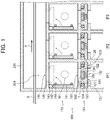
- Timing When to replace a target T is typically the time when a target T used for surface treatment has been consumed. Such timing may be experimentally determined or determined by sensing a decrease over time in the mass of a target T by means of a known mechanism (not shown) and using the sensing result as the basis for determination.
- FIG. 6 is a cross-sectional view showing the state where the shutter plate 141 at the position P1 covers the opening 146.
- heating of the target T at the position P1 where replacement is carried out is stopped.
- the shutter plate 141 at the position P1 is rotated to close the opening 146, whereby the target retaining portion 121 at the position P1 is isolated from the reduced pressure space 204.
- the valve 161 at the position P1 is opened, whereby the target T of the target retaining portion 121 at the position P1 is exposed to the air and cooled down.
- the shutter plate 141 covering the opening 146 is pressed by the atmospheric pressure, leading to increased sealing tightness.
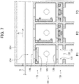
- FIG. 7 is a cross-sectional view showing the state where the target retaining portion 121 at the position P1 has been pulled out.
- the target retaining portion 121 at the position P1 is pulled out as shown in FIG. 7 .
- the grip portion 130 may be held to pull out the target retaining portion 121 along the rail grooves 131.
- the ring-like member 127 is removed, and the target T which has been consumed is taken out from the recess 125. Then, a new target T is disposed in the recess 125, whereafter the ring-like member 127 is fitted thereto. Thus, the new target T is retained in the target retaining portion 121.
- the target retaining portion 121 retaining the new target T is inserted into the pair of rail grooves 131 at the position P1.
- the target retaining portion 121 at the position P1 again assumes the same state as in FIG. 6 .
- Heating of the new target T at the position P1 may be started at this point of time.
- the valve 161 is closed, and thereafter, the shutter plate 141 at the position P1 is rotated to open the opening 146.
- the shutter plate 141 at the position P1 again assumes the same state as in FIG. 1 .
- the target T at the position P1 is exposed to the reduced pressure space 204 again and starts to be used for surface treatment of the material S to be surface-treated.
- only the target T at the position P1 can be easily replaced without entirely releasing the inside atmosphere of the chamber 201 to the air and cooling down the inside of the chamber 201.
- another target T for example on the more downstream side than the position P1 in the conveyance direction (at the position P2, P3, or the like) can be replaced in the same manner.
- the material S to be surface-treated is conveyed and continuously subjected to surface treatment using targets T at other positions (e.g., positions P2, P3, and the like).
- a target T can be replaced without stopping the operation (conveyance of the material S to be surface-treated, and continuous surface treatment of the material S to be surface-treated that is conveyed).
- the number of the target retaining portions 121 is preferably at least two in order to achieve the above effect. In other words, there are preferably provided, at least, one target retaining portion 121 whose target T is replaced and another target retaining portion 121 used for surface treatment during the replacement.
- the conveyance speed can be increased with increasing number of the target retaining portions 121 disposed along the conveyance direction (rolling direction) of the material S to be surface-treated. Therefore, the number of the target retaining portions 121 is more preferably at least four. However, if the number thereof is too large, problems may arise; for instance, the chamber 201 may become too long. Therefore, the number of the target retaining portions 121 is preferably up to eighty.
- the number of the target retaining portions 121 removed from the chamber 201 at a time is not particularly limited, and to replace a target T without stopping the operation, at least one target retaining portion 121 is preferably not removed.
- the installation of the valve 161 as well as its opening and closing operation may be omitted.
- the target retaining portion 121 may be pulled out (see FIG. 7 ) without opening the valve 161 if it is possible.
- the target retaining portion 121 is naturally exposed to the air and cooled down.
- the shutter plate 141 covering the opening 146 is pressed by the atmospheric pressure, so that sealing tightness increases.
- a target T which has been consumed is taken out and a new target T is retained in the same manner as above.
- the target retaining portion 121 retaining the new target T is inserted into the rail grooves 131.
- the shutter plate 141 is rotated to open the opening 146 while heating of the new target T is started.
- the new target T is exposed to the reduced pressure space 204 again and starts to be used for surface treatment of the material S to be surface-treated.
- FIG. 8 is a schematic view showing an arrangement of the targets T.
- the number of the targets T in each target retaining portion 121 is not particularly limited and suitably set in accordance with the length of the material S to be surface-treated in the width direction of the material S.
- FIGS. 2 to 4 an example is illustrated in which three targets T are retained in one target retaining portion 121 along the width direction of the material S to be surface-treated.
- those figures are merely schematic views, and for example, seven targets T may be retained in one target retaining portion 121 as shown in FIG. 8 .
- the targets T of respective target retaining portions 121 are arranged in a linear manner along the conveyance direction of the material S to be surface-treated (the direction of arrow A), as shown by imaginary line L1.
- FIG. 9 is a schematic view showing another arrangement of the targets T.
- the targets T of respective target retaining portions 121 may be arranged in a staggered manner (to have a zigzag shape) along the conveyance direction of the material S to be surface-treated (the direction of arrow A), as shown by imaginary line L2. This configuration is preferred because surface treatment using the targets T is carried out evenly and entirely across the width direction of the material S to be surface-treated.
- FIG. 10 is a cross-sectional view showing the state where the target replacement apparatuses 101 are disposed on both sides of the material S to be surface-treated that is conveyed.
- the targets T are disposed on both sides of the material S to be surface-treated that is conveyed in the chamber 201.
- coatings can be simultaneously formed on both surfaces of the material S to be surface-treated that is conveyed, so that uniform coatings can be formed.
- FIG. 11 is a cross-sectional view showing the state where the target replacement apparatuses 101 are disposed on both sides of the material S to be surface-treated that is conveyed in a longitudinal direction.
- the material S to be surface-treated is conveyed in the longitudinal direction (upward direction from below in FIG. 11 ).
- the targets T and the target replacement apparatus or apparatuses 101 can be disposed on either or both sides of the material S to be surface-treated that is conveyed.
- coatings can be simultaneously formed on both surfaces of the material S to be surface-treated that is conveyed, so that uniform coatings can be formed.
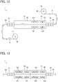
- FIG. 12 is a schematic view schematically showing a surface treatment facility 1.
- the surface treatment facility 1 includes a payoff reel 19.
- a coil 11 before conveyance formed from the material S to be surface-treated is hung on the payoff reel 19.
- the material S to be surface-treated that is pulled out from the payoff reel 19 is passed through various sections of the surface treatment facility 1 and then again wound by a winding reel 20 to form a coil 18 after conveyance.
- the surface treatment facility 1 includes the entry decompression facility 21, the pretreatment facility 31, the coating formation facility 41 and the exit decompression facility 51 in order along the direction in which the material S to be surface-treated is conveyed.
- the entry decompression facility 21 has multistage entry decompression chambers 22.
- the pretreatment facility 31 has a pretreatment chamber 32.
- the coating formation facility 41 has a coating formation chamber 42.
- the exit decompression facility 51 has multistage exit decompression chambers 52.
- the material S to be surface-treated is conveyed in an air atmosphere except for the inside of the entry decompression chambers 22, the pretreatment chamber 32, the coating formation chamber 42 and the exit decompression chambers 52.
- composition and the type of the material S to be surface-treated are not particularly limited, and examples of the material S to be surface-treated include a metal band, a film and a semiconductor.
- the material S to be surface-treated is a grain oriented electrical steel sheet having undergone final annealing, which is one type of metal band, is taken as an example and described. That is, the coil 11 before conveyance formed from a grain oriented electrical steel sheet S having undergone final annealing (hereinafter also simply called "steel sheet S") is hung on the payoff reel 19.
- a grain oriented electrical steel sheet S having undergone final annealing hereinafter also simply called "steel sheet S"
- a grain oriented electrical steel sheet having undergone final annealing has a forsterite coating.
- the steel sheet S When the steel sheet S has a forsterite coating, the steel sheet S is polished, for instance, in a polishing facility (not shown) to remove the forsterite coating before being introduced into the entry decompression chambers 22 of the entry decompression facility 21.
- a polishing facility not shown
- the steel sheet S When the steel sheet S does not have an oxide coating such as a forsterite coating, the steel sheet S is introduced into the entry decompression chambers 22 of the entry decompression facility 21 without a polishing process.
- the steel sheet S (the grain oriented electrical steel sheet having no forsterite coating) is introduced into the entry decompression chambers 22 of the entry decompression facility 21.
- the internal pressure in the multistage entry decompression chambers 22 is reduced stepwise toward the pretreatment chamber 32 and the coating formation chamber 42.
- the pressure applied to the steel sheet S approaches the internal pressure in the pretreatment chamber 32 and the coating formation chamber 42 from the atmospheric pressure.
- the number of the steps of the entry decompression chambers 22 is preferably at least three.
- the steel sheet S (the grain oriented electrical steel sheet having no forsterite coating) having been passed through the entry decompression chambers 22 is introduced into the pretreatment chamber 32 of the pretreatment facility 31 and subjected to pretreatment under a reduced pressure condition to remove impurities adhering to the surface.
- the steel sheet S (the grain oriented electrical steel sheet having no forsterite coating) having undergone the pretreatment is introduced into the coating formation chamber 42 of the coating formation facility 41.
- a coating is formed on the surface of the steel sheet S conveyed through the coating formation chamber 42 under a reduced pressure condition.
- the steel sheet S on which the coating has been formed is introduced into the exit decompression chambers 52 of the exit decompression facility 51.
- the internal pressure in the multistage exit decompression chambers 52 is increased stepwise with distance away from the coating formation chamber 42.
- the pressure applied to the steel sheet S returns from the internal pressure in the pretreatment chamber 32 and the coating formation chamber 42 to the atmospheric pressure.
- the number of the steps of the exit decompression chambers 52 is preferably at least three.
- the steel sheet S having been passed through the exit decompression facility 51 is then wound around the winding reel 20 to form the coil 18 after conveyance.
- the pretreatment facility 31 and the coating formation facility 41 are described in further detail. First, the coating formation facility 41 is described.
- Air is discharged from the inside of the coating formation chamber 42 of the coating formation facility 41 to form a reduced pressure space.
- a coating is formed on the surface of the steel sheet S (the grain oriented electrical steel sheet having no forsterite coating) that is conveyed through the reduced pressure space of the coating formation chamber 42 by a PVD (Physical Vapor Deposition) method.
- PVD Physical Vapor Deposition
- Raw material gas (atmospheric gas) for coating formation such as nitrogen gas for instance, is introduced into the coating formation chamber 42.
- the steel sheet S is heated, and a coating such as a nitride coating is formed on the surface of the steel sheet S.
- any means may be suitably adopted without particular limitation as long as it is a means that does not require oxygen, such as induction heating (IH), electron beam irradiation, laser light, or infrared light.
- IH induction heating
- laser light or infrared light.
- a preferred PVD method is an ion plating method.
- the coating formation temperature is preferably 300°C to 600°C, and the pressure (internal pressure) in the coating formation chamber 42 is preferably 0.1 to 100 Pa.
- a bias voltage of -10 to -100 V is preferably applied with the steel sheet S serving as the cathode.
- the coating formation rate can be increased when plasma is used for ionization of a raw material.
- a nitride coating is preferred, a metal nitride coating is more preferred, and a metal nitride coating including at least one metal selected from the group consisting of Zn, V, Cr, Mn, Fe, Co, Ni, Cu, Ti, Y, Nb, Mo, Hf, Zr, W and Ta is even more preferred.
- These coatings can easily have a rock salt structure, and since this structure easily matches the body-centered cubic lattice of the steel substrate of the steel sheet S, the adhesion of the coating can be improved.
- the coating formed on the steel sheet S may be a single layer coating or a multilayer coating.
- gas generated upon reaction on the surface of the steel sheet S and raw material gas introduced are dominant in terms of the amount. Meanwhile, when gas is excessively discharged, the raw material gas may not be sufficiently delivered to the steel sheet S. In consideration of these points, gas is discharged to achieve a desired internal pressure (the same applies to the pretreatment chamber 32).
- exhaust ports, inlet ports for introducing the raw material gas, and the like of the coating formation chamber 42 are not illustrated (the same applies to the pretreatment chamber 32).
- the amount of discharged gas is preferably 0.5 to 1 time as much as the amount of introduced raw material gas.
- the attachment and detachment mechanisms 151 and the isolating mechanisms 171 (neither of which are shown in FIG. 12 ) of the plurality of target replacement apparatuses 101 as described with reference to FIGS. 1 to 7 are disposed on the bottom surface side and the top surface side of the conveyed steel sheet S (see FIG. 10 ) in the coating formation chamber 42 that is a chamber.
- the steel sheet S may be conveyed in a longitudinal direction (see FIG. 11 ) in the coating formation chamber 42.
- the above-described valves 161 (not shown in FIG. 12 ) are disposed in the coating formation chamber 42.
- targets are used as a raw material of the resulting coating.
- Each target retaining portion 121 (not shown in FIG. 12 ) retains a plurality of targets such that the targets are aligned in a direction perpendicular to the conveyance direction of the steel sheet S.
- a plurality of targets may be arranged in a linear manner (see FIG. 8 ) or a staggered manner (see FIG. 9 ) along the conveyance direction of the steel sheet S.
- the target replacement apparatus 101 when a target at a certain position in the conveyance direction of the steel sheet S is consumed, the target at that position can be easily replaced without stopping the operation of the surface treatment facility 1.
- pretreatment facility 31 pretreatment chamber 32 disposed on the upstream side of the coating formation facility 41 (coating formation chamber 42) is described.
- the steel sheet S having been passed through the entry decompression chambers 22 is introduced into the pretreatment chamber 32 of the pretreatment facility 31 and subjected to the pretreatment in which impurities such as oxides adhering to the surface of the steel sheet S are removed under a reduced pressure condition.
- the pretreatment prior to coating formation allows a coating (e.g., a nitride coating) later formed in the coating formation facility 41 to have remarkably improved adhesion to the steel sheet S. Therefore, although not essential, it is preferable to provide the pretreatment facility 31.
- a coating e.g., a nitride coating
- a favorable method of the pretreatment is ion sputtering.
- ion sputtering preferred examples include ions of inert gases such as argon and nitrogen and ions of metals such as Ti and Cr.
- the pressure in the pretreatment chamber 32 is reduced, and the internal pressure of the pretreatment chamber 32 is preferably 0.0001 to 1 Pa in order to increase the mean free path of sputtering ions.
- a bias voltage of -100 to -1000 V is preferably applied with the steel sheet S serving as the cathode.
- FIG. 13 is a schematic view showing a surface treatment facility 1 in which the target replacement apparatuses 101 are disposed in the pretreatment chamber 32. In FIG. 13 , part of the surface treatment facility 1 is not illustrated.
- the pretreatment can be carried out using a metal target by a PVD method (particularly, the ion plating method).
- the attachment and detachment mechanisms 151 and the isolating mechanisms 171 (neither of which are shown in FIG. 13 ) of the plurality of target replacement apparatuses 101 as described with reference to FIGS. 1 to 7 can be disposed on the bottom surface side and the top surface side of the conveyed steel sheet S (see FIG. 10 ) in the pretreatment chamber 32 that is a chamber.
- the steel sheet S may be conveyed in a longitudinal direction (see FIG. 11 ) in the pretreatment chamber 32.
- the above-described valves 161 (not shown in FIG. 13 ) are disposed in the pretreatment chamber 32.
- each target retaining portion 121 retains a plurality of targets such that the targets are aligned in a direction perpendicular to the conveyance direction of the steel sheet S.
- a plurality of targets may be arranged in a linear manner (see FIG. 8 ) or a staggered manner (see FIG. 9 ) along the conveyance direction of the steel sheet S.
- the target replacement apparatus 101 when a target at a certain position in the conveyance direction of the steel sheet S is consumed, the target at that position can be easily replaced without stopping the operation of the surface treatment facility 1.
- a coil 11 before conveyance (total mass: 8 t) of a grain oriented electrical steel sheet S (sheet thickness: 0.23 mm) having undergone final annealing was set in the surface treatment facility 1 described with reference to FIG. 12 , and coating formation was carried out.
- the conveyance speed of the steel sheet S was set to 30 m/min.
- the steel sheet S from which a forsterite coating had been removed by mechanical polishing was introduced into the pretreatment chamber 32 to remove impurities from the surfaces by Ar ion sputtering.
- a TiN coating (coating thickness: 0.3 ⁇ m) was formed on each surface of the steel sheet S by a PVD method in the coating formation chamber 42.
- the PVD method was the ion plating method, and the coating formation temperature was 400°C.
- Example 1 ten target replacement apparatuses 101 were disposed along the conveyance direction of the steel sheet S in the coating formation chamber 42, as shown in FIG. 12 .
- Each target retaining portion 121 (not shown in FIG. 12 ) retained three targets such that the targets are aligned in the width direction of the steel sheet S.
- Each target had a diameter of 100 mm and a height of 50 mm.
- Example 1 two target retaining portions 121 (not shown in FIG. 12 ) were together pulled out every 2 hours, and old targets having been used in coating formation and thereby consumed were replaced by new and unused targets.
- the time to start using new targets in coating formation was set to be exactly 2 hours after the use of corresponding old targets in coating formation was stopped. In other words, in Example 1, the number of target arrays in use for coating formation was always eight.
- the coating thickness of the TiN coating formed on each surface of the steel sheet S was examined on the exit side of the coating formation chamber 42.
- the coating thickness was examined by measuring the Ti intensity using a fluorescent X-ray.
- the maintenance such as entirely releasing the inside atmosphere of the coating formation chamber 42 to the air and cooling down the inside thereof was not necessary during the test that continued 1000 hours. This made it possible to maximize the operating rate of the surface treatment facility 1 during the test. Specifically, the operating rate was about 99%.
- Targets were fixed to the inside of the coating formation chamber 42 without the target replacement apparatus 101.
- the number of target arrays in use for coating formation was set to eight, as with Example 1.
- the number of targets in each array was three in the width direction of the steel sheet S.
Landscapes
- Chemical & Material Sciences (AREA)
- Engineering & Computer Science (AREA)
- Chemical Kinetics & Catalysis (AREA)
- Materials Engineering (AREA)
- Mechanical Engineering (AREA)
- Metallurgy (AREA)
- Organic Chemistry (AREA)
- Physics & Mathematics (AREA)
- Plasma & Fusion (AREA)
- Analytical Chemistry (AREA)
- Physical Vapour Deposition (AREA)
Abstract
Description
- The present invention relates to a target replacement apparatus and a surface treatment facility.
- Grain oriented electrical steel sheets are soft magnetic materials used as materials for iron cores of transformers, generators and the like. Grain oriented electrical steel sheets have a crystal structure in which the <001> orientation that is an easy magnetization axis of iron is highly-precisely aligned in the rolling direction of the steel sheet. The texture as above is formed through final annealing of a manufacturing process of a grain oriented electrical steel sheet, which final annealing allows crystal grains with the {110}<001> orientation referred to as the so-called Goss orientation to preferentially grow to an enormous size. Grain oriented electrical steel sheets as products are required to have such magnetic properties as high magnetic flux density and low iron loss.
- The magnetic properties of a grain oriented electrical steel sheet are improved by applying a tensile stress (tension) to a steel sheet surface. As one conventional technique of applying a tensile stress to a steel sheet, a technique in which a forsterite coating of about 2 µm thickness is formed on a steel sheet surface and another coating of about 2 µm thickness primarily composed of silicon phosphate is formed on the forsterite coating is typically used. The silicon phosphate coating having a lower thermal expansion coefficient than that of the steel sheet is formed at high temperature and cooled to room temperature, whereby a tensile stress is applied to the steel sheet using a difference in thermal expansion coefficient between the steel sheet and the silicon phosphate coating. This silicon phosphate coating also acts as an insulating coating that is indispensable for a grain oriented electrical steel sheet. Owing to the insulation, a local eddy current is prevented from being generated in the steel sheet.
- A surface of the grain oriented electrical steel sheet having undergone final annealing is smoothed by chemical polishing or electrolytic polishing, and then a tensile stress is applied by means of the coating above the steel sheet, whereby iron loss can remarkably be decreased.
- Meanwhile, the forsterite coating between the steel sheet and the silicon phosphate coating adheres to the steel sheet owing to the anchoring effect. Therefore, the smoothness of the steel sheet surface inevitably deteriorates. Further, the adhesion between silicon phosphate and metal is so low that a silicon phosphate coating cannot be formed directly on a mirror-finished surface of a steel sheet. Thus, in the coating structure of a conventional grain oriented electrical steel sheet (steel sheet/ forsterite coating/ silicon phosphate coating), a surface of a steel sheet cannot be smoothed.
- To cope with it, techniques are disclosed in which, in order to maintain the smoothness of a steel sheet surface and also apply a large tensile stress to the steel sheet, a ceramic coating composed of TiN for instance is formed on the steel sheet by a CVD method or a PVD method (see Patent Literatures 1 and 2).
-
- Patent Literature 1:
JP 01-176034 A - Patent Literature 2:
JP 62-040368 A - When a material to be surface-treated, e.g., a grain oriented electrical steel sheet having no forsterite coating, is subjected to surface treatment such as coating formation by a PVD method using a sputtering target (hereinafter simply called "target"), the target is disposed in a reduced pressure space in a chamber and used under a high temperature condition. When the target is consumed with progression of the surface treatment, the target is replaced.
- Meanwhile, it is necessary to entirely release the inside atmosphere of the chamber to the air and cool down the inside of the chamber every time a target is replaced. This causes poor productivity.
- In particular, in the case where surface treatment using a target is continuously carried out on a material to be surface-treated that is conveyed, the operation of a surface treatment facility needs to be stopped every time a target is replaced, and this results in, for instance, a lower operating rate of the surface treatment facility.
- When surface treatment is carried out by an ion plating method which is one of PVD methods, a magnet for plasma induction is disposed on the back side of a target (on the opposite side from the side closer to the material to be surface-treated). Therefore, a huge target cannot be used, and a relatively small target is used. Accordingly, a target is consumed more quickly, so that a target needs to be replaced more frequently.
- The present invention has been made in view of the foregoing and an object of the invention is to provide a target replacement apparatus that enables easy replacement of a target used in a PVD method, as well as a surface treatment facility using the apparatus.
- The present inventors have made an intensive study and as a result found that when the structure described below is employed, the foregoing object is achieved. The invention has been thus completed.
- Specifically, the present invention provides the following [1] to [21].
- [1] A target replacement apparatus for use in replacement of a sputtering target, the sputtering target being used to carry out surface treatment by a physical vapor deposition method on a material to be surface-treated that is situated in a reduced pressure space of a chamber, the target replacement apparatus comprising:
- a target retaining portion retaining the sputtering target;
- an attachment and detachment mechanism used to detachably attach the target retaining portion to the chamber at a position where the sputtering target faces the material to be surface-treated that is situated in the reduced pressure space; and
- an isolating mechanism operable to isolate the target retaining portion attached to the chamber from the reduced pressure space in an openable and closable manner.
- [2] The target replacement apparatus according to [1] above,
wherein the material to be surface-treated is conveyed through the reduced pressure space and continuously subjected to surface treatment by use of the sputtering target. - [3] The target replacement apparatus according to [2] above,
wherein the attachment and detachment mechanism is a mechanism used to arrange a plurality of the target retaining portions in parallel along a conveyance direction of the material to be surface-treated and attach separately the plurality of the target retaining portions to the chamber in a detachable manner, and
wherein the isolating mechanism is a mechanism operable to isolate separately the plurality of the target retaining portions arranged in parallel along the conveyance direction from the reduced pressure space in an openable and closable manner. - [4] The target replacement apparatus according to [2] or [3] above,
wherein the target retaining portion retains a plurality of the sputtering targets such that the plurality of the sputtering targets are aligned in a direction perpendicular to the conveyance direction of the material to be surface-treated. - [5] The target replacement apparatus according to [4] above,
wherein a plurality of the sputtering targets are arranged in a linear manner along the conveyance direction of the material to be surface-treated. - [6] The target replacement apparatus according to [4] above,
wherein a plurality of the sputtering targets are arranged in a staggered manner along the conveyance direction of the material to be surface-treated. - [7] The target replacement apparatus according to any one of [2] to [6] above,
wherein the material to be surface-treated is conveyed in a longitudinal direction. - [8] The target replacement apparatus according to any one of [2] to [7] above,
wherein the target replacement apparatus is disposed on each side of the material to be surface-treated that is conveyed. - [9] The target replacement apparatus according to any one of [1] to [8] above, further comprising a valve used to expose the target retaining portion isolated from the reduced pressure space, to the air.
- [10] The target replacement apparatus according to any one of [1] to [9] above,
wherein the material to be surface-treated is a metal band. - [11] The target replacement apparatus according to any one of [1] to [10] above,
wherein the material to be surface-treated is a grain oriented electrical steel sheet having no forsterite coating. - [12] A surface treatment facility for continuously carrying out surface treatment, by a physical vapor deposition method using a sputtering target, on a material to be surface-treated that is conveyed, the surface treatment facility comprising:
- a chamber having a reduced pressure space therein, the material to be surface-treated being conveyed through the reduced pressure space;
- a target retaining portion retaining the sputtering target;
- an attachment and detachment mechanism used to detachably attach the target retaining portion to the chamber at a position where the sputtering target faces the material to be surface-treated that is conveyed through the reduced pressure space; and
- an isolating mechanism operable to isolate the target retaining portion attached to the chamber from the reduced pressure space in an openable and closable manner.
- [13] The target replacement apparatus according to [12] above,
wherein the attachment and detachment mechanism is a mechanism used to arrange a plurality of the target retaining portions in parallel along a conveyance direction of the material to be surface-treated and attach separately the plurality of the target retaining portions to the chamber in a detachable manner, and
wherein the isolating mechanism is a mechanism operable to isolate separately the plurality of the target retaining portions arranged in parallel along the conveyance direction from the reduced pressure space in an openable and closable manner. - [14] The surface treatment facility according to [12] or [13] above,
wherein the target retaining portion retains a plurality of the sputtering targets such that the plurality of the sputtering targets are aligned in a direction perpendicular to the conveyance direction of the material to be surface-treated. - [15] The surface treatment facility according to [14] above,
wherein a plurality of the sputtering targets are arranged in a linear manner along the conveyance direction of the material to be surface-treated. - [16] The surface treatment facility according to [14] above,
wherein a plurality of the sputtering targets are arranged in a staggered manner along the conveyance direction of the material to be surface-treated. - [17] The surface treatment facility according to any one of [12] to [16] above,
wherein the material to be surface-treated is conveyed in a longitudinal direction. - [18] The surface treatment facility according to any one of [12] to [17] above,
wherein the attachment and detachment mechanism and the isolating mechanism are disposed on each side of the material to be surface-treated that is conveyed. - [19] The surface treatment facility according to any one of [12] to [18] above, further comprising a valve used to expose the target retaining portion isolated from the reduced pressure space, to the air.
- [20] The surface treatment facility according to any one of [12] to [19] above,
wherein the material to be surface-treated is a metal band. - [21] The surface treatment facility according to any one of [12] to [20] above,
wherein the material to be surface-treated is a grain oriented electrical steel sheet having no forsterite coating. - The present invention makes it possible to provide a target replacement apparatus that enables easy replacement of a target used in a PVD method, as well as a surface treatment facility using the apparatus.
-
- [
FIG. 1] FIG. 1 is a cross-sectional view showing a target replacement apparatus along with a chamber. - [
FIG. 2] FIG. 2 is an exploded perspective view showing a target retaining portion. - [
FIG. 3] FIG. 3 is a perspective view showing an attachment and detachment mechanism. - [
FIG. 4] FIG. 4 is a perspective view showing the state where the target retaining portion is inserted in rail grooves. - [
FIG. 5] FIG. 5 is a perspective view showing an isolating mechanism. - [
FIG. 6] FIG. 6 is a cross-sectional view showing the state where a shutter plate at a position P1 covers an opening. - [
FIG. 7] FIG. 7 is a cross-sectional view showing the state where the target retaining portion at the position P1 has been pulled out. - [
FIG. 8] FIG. 8 is a schematic view showing an arrangement of targets. - [
FIG. 9] FIG. 9 is a schematic view showing another arrangement of targets. - [
FIG. 10] FIG. 10 is a cross-sectional view showing the state where the target replacement apparatuses are disposed on both sides of a material to be surface-treated that is conveyed. - [
FIG. 11] FIG. 11 is a cross-sectional view showing the state where the target replacement apparatuses are disposed on both sides of a material to be surface-treated that is conveyed in a longitudinal direction. - [
FIG. 12] FIG. 12 is a schematic view schematically showing a surface treatment facility. - [
FIG. 13] FIG. 13 is a schematic view showing a surface treatment facility in which the target replacement apparatuses are disposed in a pretreatment chamber. - Embodiments of the present invention are described below with reference to the drawings. However, the present invention should not be construed as being limited to the following embodiment. In the figures referred to below, some parts of members are cut away and illustrated.
-
FIG. 1 is a cross-sectional view showing atarget replacement apparatus 101 along with achamber 201. - Air is discharged from the inside of the
chamber 201 through an exhaust port (not shown) to form a reducedpressure space 204. A material S to be surface-treated is conveyed through the reducedpressure space 204 of thechamber 201 in a direction of arrow A (also called a conveyance direction). When the material S to be surface-treated is a rolled metal band, the material S to be surface-treated is conveyed in the rolling direction, the detail of which material S is described later. - In the reduced
pressure space 204, surface treatment such as coating formation is continuously carried out by a PVD method on the material S to be surface-treated that is conveyed, using targets T. For surface treatment, sputtering or arc discharge is carried out with the targets T in the reducedpressure space 204. In surface treatment, each target T is heated by a heater (not shown). - As shown in
FIG. 1 , thetarget replacement apparatus 101 includestarget retaining portions 121 retaining the targets T and also includes an attachment anddetachment mechanism 151 and an isolatingmechanism 171. - The attachment and
detachment mechanism 151 is used to arrange a plurality oftarget retaining portions 121 in parallel along the conveyance direction of the material S to be surface-treated and attach separately thetarget retaining portions 121 to thechamber 201 in a detachable manner. The targets T retained by thetarget retaining portions 121 are positioned by means of the attachment anddetachment mechanism 151 to face the material S to be surface-treated that is conveyed through the reducedpressure space 204. - The isolating
mechanism 171 is operated to isolate eachtarget retaining portion 121 attached to thechamber 201 from the reducedpressure space 204 in an openable and closable manner. To be more specific, the isolatingmechanism 171 is operated to isolate separately the plurality oftarget retaining portions 121 arranged in parallel along the conveyance direction of the material S to be surface-treated from the reducedpressure space 204 in an openable and closable manner. - Next, the respective portions (the
target retaining portion 121, the attachment anddetachment mechanism 151 and the isolating mechanism 171) of thetarget replacement apparatus 101 are described in further detail with reference toFIGS. 2 to 5 . - The
target retaining portion 121 is described with reference toFIG. 2 . Reference is also made toFIG. 1 . -
FIG. 2 is an exploded perspective view showing thetarget retaining portion 121. Thetarget retaining portion 121 includes a sheet-type retainingportion body 122 elongated in one direction. The retainingportion body 122 has a protrudingportion 123 protruding circumferentially. The protrudingportion 123 forms a protrudingsurface 124. The protrudingportion 123 is provided on its one edge face with agrip portion 130. - As shown in
FIG. 2 , recesses 125 in a cylindrical shape are provided in the retainingportion body 122 on one surface side (top surface side inFIG. 2 ) thereof. The targets T are placed in therecesses 125. The shape of the target T is not particularly limited and is preferably a round shape for the sake of the degree of freedom of handling and the efficiency of use of a raw material. The target T in this embodiment has a top hat shape and has abrim portion 126. Further, a ring-like member 127 is fitted into therecess 125 to fasten thebrim portion 126 of the target T disposed in therecess 125. The ring-like member 127 is detachably engaged in therecess 125 by a known method. The target T is retained in thetarget retaining portion 121 in this manner. - As shown in
FIG. 2 , a sealingmember 128 such as an O-ring is disposed on the protrudingsurface 124 of the protrudingportion 123. The sealingmember 128 is preferably bonded to the protrudingsurface 124. - Although not illustrated in
FIG. 2 , a magnet 129 (seeFIG. 1 ) is embedded in the retainingportion body 122 to overlap the associated target T disposed in therecess 125. Themagnet 129 is, for instance, a known magnet used in the ion plating method which is one of PVD methods. - Next, the attachment and
detachment mechanism 151 is described with reference toFIGS. 3 and4 . Reference is also made toFIG. 1 . -
FIG. 3 is a perspective view showing the attachment anddetachment mechanism 151.Rail grooves 131 are formed from achamber member 202 constituting thechamber 201. Therail grooves 131 are provided on one surface side of the material S to be surface-treated (under the material S to be surface-treated inFIG. 1 ) (not shown inFIG. 3 ) that is conveyed through thechamber 201, to extend in the width direction of the material S to be surface-treated. A pair ofrail grooves 131 face each other across agap 132. The protrudingportion 123 of thetarget retaining portion 121 and the sealingmember 128 are inserted into the pair ofrail grooves 131. Thus,FIG. 3 is a perspective view showing the state before thetarget retaining portion 121 is inserted into therail grooves 131. -
FIG. 4 is a perspective view showing the state where thetarget retaining portion 121 is inserted in therail grooves 131. The groove width (a distance in the vertical direction inFIG. 4 ) of therail groove 131 is smaller (narrower) than the total thickness of the protrudingportion 123 and the sealingmember 128. Accordingly, when thetarget retaining portion 121 is inserted in therail grooves 131, the sealingmember 128 makes close contact with thechamber member 202. Thus, the reducedpressure space 204 of thechamber 201 is tightly sealed. - As shown in
FIG. 4 , in the state where thetarget retaining portion 121 is inserted in therail grooves 131, the targets T are exposed from anopening 133 formed in thechamber member 202. Thus, the targets T retained by thetarget retaining portion 121 and the material S to be surface-treated that is conveyed through thechamber 201 are opposed to each other (see alsoFIG. 1 ). - The
target retaining portion 121 inserted in therail grooves 131 can be pulled out from therail grooves 131 and detached from thechamber 201 by, for instance, holding thegrip portion 130 to pull out thetarget retaining portion 121. - Thus, the
chamber member 202, therail grooves 131, theopening 133, the protrudingportion 123, the sealingmember 128 and other components constitute the attachment anddetachment mechanism 151 used to detachably attach the target retaining portion orportions 121 to thechamber 201. - The attachment and
detachment mechanism 151 is not limited to the embodiment described with reference toFIGS. 3 and4 . - For example, the
target retaining portion 121 is not limited to the one pulled out (inserted) in the width direction of the material S to be surface-treated and may be the one detached in the direction away from the material S to be surface-treated (in the downward direction inFIG. 1 ) . - Next, the isolating
mechanism 171 is described with reference toFIG. 5 . Reference is also made toFIG. 1 . -
FIG. 5 is a perspective view showing the isolatingmechanism 171. Anopening 146 is formed using achamber member 145 at a position between the material S to be surface-treated that is conveyed through thechamber 201, and the attachment anddetachment mechanism 151. Theopening 146 normally stay open. Accordingly, the material S to be surface-treated that is conveyed and the targets T directly face each other (seeFIG. 1 ). - A
shutter plate 141 is disposed on thechamber member 145 on the side closer to the attachment anddetachment mechanism 151. Theshutter plate 141 is rotated about ashaft 142 by an electrical effect. Theshaft 142 is rotatably retained by ashaft retaining portion 143 fixed on thechamber member 145. The axial direction of theshaft 142 is the width direction of the material S to be surface-treated. - As shown in
FIG. 5 , a sealingmember 144 such as an O-ring is disposed on one surface side (the side to cover the opening 146) of theshutter plate 141. The sealingmember 144 is preferably bonded to theshutter plate 141. - The
shutter plate 141 is rotated to close theopening 146 by an electrical effect, whereby the sealingmember 144 makes close contact with thechamber member 145. Thus, thetarget retaining portion 121 attached to thechamber 201 is isolated from the reducedpressure space 204. Theshutter plate 141 covering theopening 146 is rotated to open theopening 146 by an electrical effect. - Thus, the
shutter plate 141, theshaft 142, theshaft retaining portion 143, the sealingmember 144, thechamber member 145, theopening 146 and other components constitute the isolatingmechanism 171. - The isolating
mechanism 171 is not limited to the embodiment described with reference toFIG. 5 . - For example, the
shutter plate 141 is not limited to the one being rotated about theshaft 142 and may be the one pulled out (inserted) in the width direction of the material S to be surface-treated. - Further, as shown in
FIG. 1 , avalve 161 is provided between theopening 146 and thetarget retaining portion 121 inserted in therail grooves 131. Thevalve 161 is disposed outside thechamber 201 and connected to the inside of thechamber 201. When thevalve 161 is opened, the outside and the inside of thechamber 201 communicate with each other. - When the
shutter plate 141 covers theopening 146 to isolate thetarget retaining portion 121 from the reducedpressure space 204, once thevalve 161 is opened, thetarget retaining portion 121 is exposed to the air. - In the configuration as above, all the
shutter plates 141 are normally open and do not cover theopenings 146, as shown inFIG. 1 . In addition, thetarget retaining portions 121 are inserted in all the pairs ofrail grooves 131. At this time, since the sealingmembers 128 of thetarget retaining portions 121 make close contact with thechamber member 202, the reducedpressure space 204 is tightly sealed. - The material S to be surface-treated is conveyed through the reduced
pressure space 204 in the condition as above. Surface treatment is continuously carried out on the material S to be surface-treated that is conveyed, using the targets T. The targets T of all thetarget retaining portions 121 are used for surface treatment of the material S to be surface-treated. - Now, the case where a target T at a position P1 on the most upstream side in the conveyance direction of the material S to be surface-treated is replaced is described by reference to
FIGS. 6 and7 . - When to replace a target T is typically the time when a target T used for surface treatment has been consumed. Such timing may be experimentally determined or determined by sensing a decrease over time in the mass of a target T by means of a known mechanism (not shown) and using the sensing result as the basis for determination.
-
FIG. 6 is a cross-sectional view showing the state where theshutter plate 141 at the position P1 covers theopening 146. First, heating of the target T at the position P1 where replacement is carried out is stopped. Then, as shown inFIG. 6 , theshutter plate 141 at the position P1 is rotated to close theopening 146, whereby thetarget retaining portion 121 at the position P1 is isolated from the reducedpressure space 204. Subsequently, thevalve 161 at the position P1 is opened, whereby the target T of thetarget retaining portion 121 at the position P1 is exposed to the air and cooled down. At this time, theshutter plate 141 covering theopening 146 is pressed by the atmospheric pressure, leading to increased sealing tightness. -
FIG. 7 is a cross-sectional view showing the state where thetarget retaining portion 121 at the position P1 has been pulled out. Next, with theshutter plate 141 at the position P1 covering theopening 146, thetarget retaining portion 121 at the position P1 is pulled out as shown inFIG. 7 . At this time, thegrip portion 130 may be held to pull out thetarget retaining portion 121 along therail grooves 131. - In the
target retaining portion 121 thus pulled out, the ring-like member 127 is removed, and the target T which has been consumed is taken out from therecess 125. Then, a new target T is disposed in therecess 125, whereafter the ring-like member 127 is fitted thereto. Thus, the new target T is retained in thetarget retaining portion 121. - The
target retaining portion 121 retaining the new target T is inserted into the pair ofrail grooves 131 at the position P1. Thus, thetarget retaining portion 121 at the position P1 again assumes the same state as inFIG. 6 . Heating of the new target T at the position P1 may be started at this point of time. Then, thevalve 161 is closed, and thereafter, theshutter plate 141 at the position P1 is rotated to open theopening 146. Thus, theshutter plate 141 at the position P1 again assumes the same state as inFIG. 1 . The target T at the position P1 is exposed to the reducedpressure space 204 again and starts to be used for surface treatment of the material S to be surface-treated. Thus, only the target T at the position P1 can be easily replaced without entirely releasing the inside atmosphere of thechamber 201 to the air and cooling down the inside of thechamber 201. - After the target T at the position P1 is replaced, another target T for example on the more downstream side than the position P1 in the conveyance direction (at the position P2, P3, or the like) can be replaced in the same manner.
- Even while a target T at one position (e.g., position P1) is replaced, the material S to be surface-treated is conveyed and continuously subjected to surface treatment using targets T at other positions (e.g., positions P2, P3, and the like).
- Therefore, according to this embodiment, a target T can be replaced without stopping the operation (conveyance of the material S to be surface-treated, and continuous surface treatment of the material S to be surface-treated that is conveyed).
- The number of the
target retaining portions 121 is preferably at least two in order to achieve the above effect. In other words, there are preferably provided, at least, onetarget retaining portion 121 whose target T is replaced and anothertarget retaining portion 121 used for surface treatment during the replacement. - The conveyance speed can be increased with increasing number of the
target retaining portions 121 disposed along the conveyance direction (rolling direction) of the material S to be surface-treated. Therefore, the number of thetarget retaining portions 121 is more preferably at least four. However, if the number thereof is too large, problems may arise; for instance, thechamber 201 may become too long. Therefore, the number of thetarget retaining portions 121 is preferably up to eighty. - The number of the
target retaining portions 121 removed from thechamber 201 at a time is not particularly limited, and to replace a target T without stopping the operation, at least onetarget retaining portion 121 is preferably not removed. - The installation of the
valve 161 as well as its opening and closing operation may be omitted. For instance, after theshutter plate 141 is rotated and theopening 146 is closed (seeFIG. 6 ), thetarget retaining portion 121 may be pulled out (seeFIG. 7 ) without opening thevalve 161 if it is possible. In this case, by being pulled out, thetarget retaining portion 121 is naturally exposed to the air and cooled down. After thetarget retaining portion 121 is pulled out, theshutter plate 141 covering theopening 146 is pressed by the atmospheric pressure, so that sealing tightness increases. - Next, in the
target retaining portion 121 thus pulled out, a target T which has been consumed is taken out and a new target T is retained in the same manner as above. Thetarget retaining portion 121 retaining the new target T is inserted into therail grooves 131. - Then, the
shutter plate 141 is rotated to open theopening 146 while heating of the new target T is started. Thus, the new target T is exposed to the reducedpressure space 204 again and starts to be used for surface treatment of the material S to be surface-treated. - Next, the arrangement of the targets T is described with reference to
FIGS. 8 and 9 . -
FIG. 8 is a schematic view showing an arrangement of the targets T. The number of the targets T in eachtarget retaining portion 121 is not particularly limited and suitably set in accordance with the length of the material S to be surface-treated in the width direction of the material S. InFIGS. 2 to 4 , an example is illustrated in which three targets T are retained in onetarget retaining portion 121 along the width direction of the material S to be surface-treated. However, those figures are merely schematic views, and for example, seven targets T may be retained in onetarget retaining portion 121 as shown inFIG. 8 . - In
FIG. 8 , the targets T of respectivetarget retaining portions 121 are arranged in a linear manner along the conveyance direction of the material S to be surface-treated (the direction of arrow A), as shown by imaginary line L1. -
FIG. 9 is a schematic view showing another arrangement of the targets T. As shown inFIG. 9 , the targets T of respectivetarget retaining portions 121 may be arranged in a staggered manner (to have a zigzag shape) along the conveyance direction of the material S to be surface-treated (the direction of arrow A), as shown by imaginary line L2. This configuration is preferred because surface treatment using the targets T is carried out evenly and entirely across the width direction of the material S to be surface-treated. - Next, modifications of the arrangement of the
target replacement apparatuses 101 are described with reference toFIGS. 10 and11 . -
FIG. 10 is a cross-sectional view showing the state where thetarget replacement apparatuses 101 are disposed on both sides of the material S to be surface-treated that is conveyed. InFIG. 10 , the targets T are disposed on both sides of the material S to be surface-treated that is conveyed in thechamber 201. - In the case of forming coatings on both surfaces of the material S to be surface-treated that is conveyed, if coating formation is carried out on a surface-by-surface basis, deflection may occur in the surface-treated material S after a coating is formed only on one surface thereof, and this deflection may cause nonuniform coatings.
- As shown in
FIG. 10 , however, when the targets T are disposed on both sides of the material S to be surface-treated, coatings can be simultaneously formed on both surfaces of the material S to be surface-treated that is conveyed, so that uniform coatings can be formed. -
FIG. 11 is a cross-sectional view showing the state where thetarget replacement apparatuses 101 are disposed on both sides of the material S to be surface-treated that is conveyed in a longitudinal direction. InFIG. 11 , the material S to be surface-treated is conveyed in the longitudinal direction (upward direction from below inFIG. 11 ). Even in this case, the targets T and the target replacement apparatus orapparatuses 101 can be disposed on either or both sides of the material S to be surface-treated that is conveyed. As shown inFIG. 11 , when the apparatuses are disposed on both sides of the material S to be surface-treated, coatings can be simultaneously formed on both surfaces of the material S to be surface-treated that is conveyed, so that uniform coatings can be formed. - Next, one embodiment of the surface treatment facility of the invention is described below with reference to
FIG. 12 . -
FIG. 12 is a schematic view schematically showing a surface treatment facility 1. The surface treatment facility 1 includes apayoff reel 19. Acoil 11 before conveyance formed from the material S to be surface-treated is hung on thepayoff reel 19. The material S to be surface-treated that is pulled out from thepayoff reel 19 is passed through various sections of the surface treatment facility 1 and then again wound by a windingreel 20 to form acoil 18 after conveyance. - The surface treatment facility 1 includes the
entry decompression facility 21, thepretreatment facility 31, thecoating formation facility 41 and theexit decompression facility 51 in order along the direction in which the material S to be surface-treated is conveyed. - The
entry decompression facility 21 has multistageentry decompression chambers 22. Thepretreatment facility 31 has apretreatment chamber 32. Thecoating formation facility 41 has acoating formation chamber 42. Theexit decompression facility 51 has multistageexit decompression chambers 52. - The material S to be surface-treated is conveyed in an air atmosphere except for the inside of the
entry decompression chambers 22, thepretreatment chamber 32, thecoating formation chamber 42 and theexit decompression chambers 52. - The composition and the type of the material S to be surface-treated are not particularly limited, and examples of the material S to be surface-treated include a metal band, a film and a semiconductor.
- In the following, the case where the material S to be surface-treated is a grain oriented electrical steel sheet having undergone final annealing, which is one type of metal band, is taken as an example and described. That is, the
coil 11 before conveyance formed from a grain oriented electrical steel sheet S having undergone final annealing (hereinafter also simply called "steel sheet S") is hung on thepayoff reel 19. - Typically, a grain oriented electrical steel sheet having undergone final annealing has a forsterite coating.
- When the steel sheet S has a forsterite coating, the steel sheet S is polished, for instance, in a polishing facility (not shown) to remove the forsterite coating before being introduced into the
entry decompression chambers 22 of theentry decompression facility 21. When the steel sheet S does not have an oxide coating such as a forsterite coating, the steel sheet S is introduced into theentry decompression chambers 22 of theentry decompression facility 21 without a polishing process. - The steel sheet S (the grain oriented electrical steel sheet having no forsterite coating) is introduced into the
entry decompression chambers 22 of theentry decompression facility 21. The internal pressure in the multistageentry decompression chambers 22 is reduced stepwise toward thepretreatment chamber 32 and thecoating formation chamber 42. Thus, the pressure applied to the steel sheet S approaches the internal pressure in thepretreatment chamber 32 and thecoating formation chamber 42 from the atmospheric pressure. - Since the internal pressure is changed stepwise, wavy distortion of the steel sheet S that may be caused by the pressure difference can be minimized. The number of the steps of the
entry decompression chambers 22 is preferably at least three. - The steel sheet S (the grain oriented electrical steel sheet having no forsterite coating) having been passed through the
entry decompression chambers 22 is introduced into thepretreatment chamber 32 of thepretreatment facility 31 and subjected to pretreatment under a reduced pressure condition to remove impurities adhering to the surface. - The steel sheet S (the grain oriented electrical steel sheet having no forsterite coating) having undergone the pretreatment is introduced into the
coating formation chamber 42 of thecoating formation facility 41. A coating is formed on the surface of the steel sheet S conveyed through thecoating formation chamber 42 under a reduced pressure condition. - The steel sheet S on which the coating has been formed is introduced into the
exit decompression chambers 52 of theexit decompression facility 51. The internal pressure in the multistageexit decompression chambers 52 is increased stepwise with distance away from thecoating formation chamber 42. Thus, the pressure applied to the steel sheet S returns from the internal pressure in thepretreatment chamber 32 and thecoating formation chamber 42 to the atmospheric pressure. - Since the internal pressure is changed stepwise, wavy distortion of the steel sheet S that may be caused by the pressure difference can be minimized. The number of the steps of the
exit decompression chambers 52 is preferably at least three. - The steel sheet S having been passed through the
exit decompression facility 51 is then wound around the windingreel 20 to form thecoil 18 after conveyance. - Next, the
pretreatment facility 31 and thecoating formation facility 41 are described in further detail. First, thecoating formation facility 41 is described. - Air is discharged from the inside of the
coating formation chamber 42 of thecoating formation facility 41 to form a reduced pressure space. A coating is formed on the surface of the steel sheet S (the grain oriented electrical steel sheet having no forsterite coating) that is conveyed through the reduced pressure space of thecoating formation chamber 42 by a PVD (Physical Vapor Deposition) method. - Raw material gas (atmospheric gas) for coating formation, such as nitrogen gas for instance, is introduced into the
coating formation chamber 42. The steel sheet S is heated, and a coating such as a nitride coating is formed on the surface of the steel sheet S. - For a means for heating the steel sheet S, since the inside of the
coating formation chamber 42 is the reduced pressure space, the use of a burner or such devices is naturally improper. However, any means may be suitably adopted without particular limitation as long as it is a means that does not require oxygen, such as induction heating (IH), electron beam irradiation, laser light, or infrared light. - A preferred PVD method is an ion plating method. For ease of manufacture, the coating formation temperature is preferably 300°C to 600°C, and the pressure (internal pressure) in the
coating formation chamber 42 is preferably 0.1 to 100 Pa. During the coating formation, a bias voltage of -10 to -100 V is preferably applied with the steel sheet S serving as the cathode. The coating formation rate can be increased when plasma is used for ionization of a raw material. - For the coating formed on the steel sheet S, a nitride coating is preferred, a metal nitride coating is more preferred, and a metal nitride coating including at least one metal selected from the group consisting of Zn, V, Cr, Mn, Fe, Co, Ni, Cu, Ti, Y, Nb, Mo, Hf, Zr, W and Ta is even more preferred. These coatings can easily have a rock salt structure, and since this structure easily matches the body-centered cubic lattice of the steel substrate of the steel sheet S, the adhesion of the coating can be improved.
- The coating formed on the steel sheet S may be a single layer coating or a multilayer coating.
- In the
coating formation chamber 42, gas generated upon reaction on the surface of the steel sheet S and raw material gas introduced are dominant in terms of the amount. Meanwhile, when gas is excessively discharged, the raw material gas may not be sufficiently delivered to the steel sheet S. In consideration of these points, gas is discharged to achieve a desired internal pressure (the same applies to the pretreatment chamber 32). - In the figures, exhaust ports, inlet ports for introducing the raw material gas, and the like of the
coating formation chamber 42 are not illustrated (the same applies to the pretreatment chamber 32). - In the
coating formation chamber 42, the amount of discharged gas is preferably 0.5 to 1 time as much as the amount of introduced raw material gas. - In this embodiment, the attachment and
detachment mechanisms 151 and the isolating mechanisms 171 (neither of which are shown inFIG. 12 ) of the plurality oftarget replacement apparatuses 101 as described with reference toFIGS. 1 to 7 are disposed on the bottom surface side and the top surface side of the conveyed steel sheet S (seeFIG. 10 ) in thecoating formation chamber 42 that is a chamber. The steel sheet S may be conveyed in a longitudinal direction (seeFIG. 11 ) in thecoating formation chamber 42. The above-described valves 161 (not shown inFIG. 12 ) are disposed in thecoating formation chamber 42. - In coating formation, targets are used as a raw material of the resulting coating. Each target retaining portion 121 (not shown in
FIG. 12 ) retains a plurality of targets such that the targets are aligned in a direction perpendicular to the conveyance direction of the steel sheet S. A plurality of targets may be arranged in a linear manner (seeFIG. 8 ) or a staggered manner (seeFIG. 9 ) along the conveyance direction of the steel sheet S. - According to the
target replacement apparatus 101, when a target at a certain position in the conveyance direction of the steel sheet S is consumed, the target at that position can be easily replaced without stopping the operation of the surface treatment facility 1. - Next, the pretreatment facility 31 (pretreatment chamber 32) disposed on the upstream side of the coating formation facility 41 (coating formation chamber 42) is described.
- The steel sheet S having been passed through the
entry decompression chambers 22 is introduced into thepretreatment chamber 32 of thepretreatment facility 31 and subjected to the pretreatment in which impurities such as oxides adhering to the surface of the steel sheet S are removed under a reduced pressure condition. - The pretreatment prior to coating formation allows a coating (e.g., a nitride coating) later formed in the
coating formation facility 41 to have remarkably improved adhesion to the steel sheet S. Therefore, although not essential, it is preferable to provide thepretreatment facility 31. - A favorable method of the pretreatment is ion sputtering. In the case of ion sputtering, preferred examples of ion species for use include ions of inert gases such as argon and nitrogen and ions of metals such as Ti and Cr.
- The pressure in the
pretreatment chamber 32 is reduced, and the internal pressure of thepretreatment chamber 32 is preferably 0.0001 to 1 Pa in order to increase the mean free path of sputtering ions. - A bias voltage of -100 to -1000 V is preferably applied with the steel sheet S serving as the cathode.
-
FIG. 13 is a schematic view showing a surface treatment facility 1 in which thetarget replacement apparatuses 101 are disposed in thepretreatment chamber 32. InFIG. 13 , part of the surface treatment facility 1 is not illustrated. - When ions of a metal such as Ti or Cr are used in the pretreatment in the
pretreatment chamber 32, the pretreatment can be carried out using a metal target by a PVD method (particularly, the ion plating method). - In this case, as shown in
FIG. 13 for instance, the attachment anddetachment mechanisms 151 and the isolating mechanisms 171 (neither of which are shown inFIG. 13 ) of the plurality oftarget replacement apparatuses 101 as described with reference toFIGS. 1 to 7 can be disposed on the bottom surface side and the top surface side of the conveyed steel sheet S (seeFIG. 10 ) in thepretreatment chamber 32 that is a chamber. The steel sheet S may be conveyed in a longitudinal direction (seeFIG. 11 ) in thepretreatment chamber 32. The above-described valves 161 (not shown inFIG. 13 ) are disposed in thepretreatment chamber 32. - Owing to the
pretreatment chamber 32 as shown inFIG. 13 , the pretreatment can be carried out simultaneously from the both sides of the steel sheet S using the targets. At this time, each target retaining portion 121 (not shown inFIG. 13 ) retains a plurality of targets such that the targets are aligned in a direction perpendicular to the conveyance direction of the steel sheet S. A plurality of targets may be arranged in a linear manner (seeFIG. 8 ) or a staggered manner (seeFIG. 9 ) along the conveyance direction of the steel sheet S. - Owing to the use of the
target replacement apparatus 101, when a target at a certain position in the conveyance direction of the steel sheet S is consumed, the target at that position can be easily replaced without stopping the operation of the surface treatment facility 1. - The present invention is specifically described below with reference to examples. However, the present invention is not limited thereto.
- A
coil 11 before conveyance (total mass: 8 t) of a grain oriented electrical steel sheet S (sheet thickness: 0.23 mm) having undergone final annealing was set in the surface treatment facility 1 described with reference toFIG. 12 , and coating formation was carried out. The conveyance speed of the steel sheet S was set to 30 m/min. To be more specific, the steel sheet S from which a forsterite coating had been removed by mechanical polishing was introduced into thepretreatment chamber 32 to remove impurities from the surfaces by Ar ion sputtering. Subsequently, a TiN coating (coating thickness: 0.3 µm) was formed on each surface of the steel sheet S by a PVD method in thecoating formation chamber 42. The PVD method was the ion plating method, and the coating formation temperature was 400°C. - In Example 1, ten
target replacement apparatuses 101 were disposed along the conveyance direction of the steel sheet S in thecoating formation chamber 42, as shown inFIG. 12 . Each target retaining portion 121 (not shown inFIG. 12 ) retained three targets such that the targets are aligned in the width direction of the steel sheet S. Each target had a diameter of 100 mm and a height of 50 mm. - In Example 1, two target retaining portions 121 (not shown in
FIG. 12 ) were together pulled out every 2 hours, and old targets having been used in coating formation and thereby consumed were replaced by new and unused targets. The time to start using new targets in coating formation was set to be exactly 2 hours after the use of corresponding old targets in coating formation was stopped. In other words, in Example 1, the number of target arrays in use for coating formation was always eight. - The coating thickness of the TiN coating formed on each surface of the steel sheet S was examined on the exit side of the
coating formation chamber 42. The coating thickness was examined by measuring the Ti intensity using a fluorescent X-ray. - The examination results revealed that the coating thickness varied very slightly as a whole.
- The maintenance such as entirely releasing the inside atmosphere of the
coating formation chamber 42 to the air and cooling down the inside thereof was not necessary during the test that continued 1000 hours. This made it possible to maximize the operating rate of the surface treatment facility 1 during the test. Specifically, the operating rate was about 99%. - Targets were fixed to the inside of the
coating formation chamber 42 without thetarget replacement apparatus 101. The number of target arrays in use for coating formation was set to eight, as with Example 1. The number of targets in each array was three in the width direction of the steel sheet S. - With the other conditions being set to be the same as those of Example 1, the coating formation was carried out, and the coating thickness of the TiN coating formed on each surface of the steel sheet S was examined on the exit side of the
coating formation chamber 42. - The examination results revealed that while there was almost no difference in coating thickness between the opposite surfaces and the coatings were uniformly formed at the beginning of the coating formation, the coating thickness started decreasing approximately 8 hours after the start of the coating formation, and substantially no coating was formed when 10 hours had elapsed. In other words, it was revealed that the maintenance was required every 8 hours in Comparative Example 1 in which the targets were fixed to the inside of the
coating formation chamber 42. - In the maintenance conducted every 8 hours, it took approximately 3 hours to release the inside atmosphere of the
coating formation chamber 42 and cool down the inside thereof and approximately 5 hours to again discharge air and heat the chamber. Accordingly, the operating rate of the surface treatment facility 1 during the test that continued 1000 hours was about 50%. -
- 1 surface treatment facility
- 11 coil before conveyance
- 18 coil after conveyance
- 19 payoff reel
- 20 winding reel
- 21 entry decompression facility
- 22 entry decompression chamber
- 31 pretreatment facility
- 32 pretreatment chamber (chamber)
- 41 coating formation facility
- 42 coating formation chamber (chamber)
- 51 exit decompression facility
- 52 exit decompression chamber
- 101 target replacement apparatus
- 121 target retaining portion
- 122 retaining portion body
- 123 protruding portion
- 124 protruding surface
- 125 recess
- 126 brim portion
- 127 ring-like member
- 128 sealing member
- 129 magnet
- 130 grip portion
- 131 rail groove
- 132 gap
- 133 opening
- 141 shutter plate
- 142 shaft
- 143 shaft retaining portion
- 144 sealing member
- 145 chamber member
- 146 opening
- 151 attachment and detachment mechanism
- 161 valve
- 171 isolating mechanism
- 201 chamber
- 202 chamber member
- 204 reduced pressure space
- A arrow
- S material to be surface-treated (grain oriented electrical steel sheet having undergone final annealing)
- T target
- P1 position
- P2 position
- P3 position
Claims (21)
- A target replacement apparatus for use in replacement of a sputtering target, the sputtering target being used to carry out surface treatment by a physical vapor deposition method on a material to be surface-treated that is situated in a reduced pressure space of a chamber, the target replacement apparatus comprising:a target retaining portion retaining the sputtering target;an attachment and detachment mechanism used to detachably attach the target retaining portion to the chamber at a position where the sputtering target faces the material to be surface-treated that is situated in the reduced pressure space; andan isolating mechanism operable to isolate the target retaining portion attached to the chamber from the reduced pressure space in an openable and closable manner.
- The target replacement apparatus according to claim 1,
wherein the material to be surface-treated is conveyed through the reduced pressure space and continuously subjected to surface treatment by use of the sputtering target. - The target replacement apparatus according to claim 2,
wherein the attachment and detachment mechanism is a mechanism used to arrange a plurality of the target retaining portions in parallel along a conveyance direction of the material to be surface-treated and attach separately the plurality of the target retaining portions to the chamber in a detachable manner, and
wherein the isolating mechanism is a mechanism operable to isolate separately the plurality of the target retaining portions arranged in parallel along the conveyance direction from the reduced pressure space in an openable and closable manner. - The target replacement apparatus according to claim 2 or 3,
wherein the target retaining portion retains a plurality of the sputtering targets such that the plurality of the sputtering targets are aligned in a direction perpendicular to the conveyance direction of the material to be surface-treated. - The target replacement apparatus according to claim 4,
wherein a plurality of the sputtering targets are arranged in a linear manner along the conveyance direction of the material to be surface-treated. - The target replacement apparatus according to claim 4,
wherein a plurality of the sputtering targets are arranged in a staggered manner along the conveyance direction of the material to be surface-treated. - The target replacement apparatus according to any one of claims 2 to 6,
wherein the material to be surface-treated is conveyed in a longitudinal direction. - The target replacement apparatus according to any one of claims 2 to 7,
wherein the target replacement apparatus is disposed on each side of the material to be surface-treated that is conveyed. - The target replacement apparatus according to any one of claims 1 to 8, further comprising a valve used to expose the target retaining portion isolated from the reduced pressure space, to the air.
- The target replacement apparatus according to any one of claims 1 to 9,
wherein the material to be surface-treated is a metal band. - The target replacement apparatus according to any one of claims 1 to 10,
wherein the material to be surface-treated is a grain oriented electrical steel sheet having no forsterite coating. - A surface treatment facility for continuously carrying out surface treatment, by a physical vapor deposition method using a sputtering target, on a material to be surface-treated that is conveyed, the surface treatment facility comprising:a chamber having a reduced pressure space therein, the material to be surface-treated being conveyed through the reduced pressure space;a target retaining portion retaining the sputtering target;an attachment and detachment mechanism used to detachably attach the target retaining portion to the chamber at a position where the sputtering target faces the material to be surface-treated that is conveyed through the reduced pressure space; andan isolating mechanism operable to isolate the target retaining portion attached to the chamber from the reduced pressure space in an openable and closable manner.
- The target replacement apparatus according to claim 12,
wherein the attachment and detachment mechanism is a mechanism used to arrange a plurality of the target retaining portions in parallel along a conveyance direction of the material to be surface-treated and attach separately the plurality of the target retaining portions to the chamber in a detachable manner, and
wherein the isolating mechanism is a mechanism operable to isolate separately the plurality of the target retaining portions arranged in parallel along the conveyance direction from the reduced pressure space in an openable and closable manner. - The surface treatment facility according to claim 12 or 13,
wherein the target retaining portion retains a plurality of the sputtering targets such that the plurality of the sputtering targets are aligned in a direction perpendicular to the conveyance direction of the material to be surface-treated. - The surface treatment facility according to claim 14,
wherein a plurality of the sputtering targets are arranged in a linear manner along the conveyance direction of the material to be surface-treated. - The surface treatment facility according to claim 14,
wherein a plurality of the sputtering targets are arranged in a staggered manner along the conveyance direction of the material to be surface-treated. - The surface treatment facility according to any one of claims 12 to 16,
wherein the material to be surface-treated is conveyed in a longitudinal direction. - The surface treatment facility according to any one of claims 12 to 17,
wherein the attachment and detachment mechanism and the isolating mechanism are disposed on each side of the material to be surface-treated that is conveyed. - The surface treatment facility according to any one of claims 12 to 18, further comprising a valve used to expose the target retaining portion isolated from the reduced pressure space, to the air.
- The surface treatment facility according to any one of claims 12 to 19,
wherein the material to be surface-treated is a metal band. - The surface treatment facility according to any one of claims 12 to 20,
wherein the material to be surface-treated is a grain oriented electrical steel sheet having no forsterite coating.
Applications Claiming Priority (2)
| Application Number | Priority Date | Filing Date | Title |
|---|---|---|---|
| JP2018067195 | 2018-03-30 | ||
| PCT/JP2019/012770 WO2019189122A1 (en) | 2018-03-30 | 2019-03-26 | Target exchanging device and surface treatment facility |
Publications (2)
| Publication Number | Publication Date |
|---|---|
| EP3778983A1 true EP3778983A1 (en) | 2021-02-17 |
| EP3778983A4 EP3778983A4 (en) | 2021-05-26 |
Family
ID=68061656
Family Applications (1)
| Application Number | Title | Priority Date | Filing Date |
|---|---|---|---|
| EP19774379.2A Pending EP3778983A4 (en) | 2018-03-30 | 2019-03-26 | Target exchanging device and surface treatment facility |
Country Status (7)
| Country | Link |
|---|---|
| US (1) | US20210025050A1 (en) |
| EP (1) | EP3778983A4 (en) |
| JP (1) | JP6601601B1 (en) |
| KR (1) | KR102496043B1 (en) |
| CN (1) | CN111868294B (en) |
| RU (1) | RU2743387C1 (en) |
| WO (1) | WO2019189122A1 (en) |
Families Citing this family (3)
| Publication number | Priority date | Publication date | Assignee | Title |
|---|---|---|---|---|
| CN113491841B (en) | 2020-03-18 | 2025-08-01 | 中硼(厦门)医疗器械有限公司 | Neutron capture therapy system |
| EP4726071A1 (en) * | 2024-09-20 | 2026-04-15 | VON ARDENNE Asset GmbH & Co. KG | Processing device exchange system and vacuum assembly |
| CN120536875B (en) * | 2025-07-28 | 2025-10-31 | 长沙市熔材科技有限公司 | Vacuum chamber continuous feeding mechanism and physical vapor deposition device |
Family Cites Families (25)
| Publication number | Priority date | Publication date | Assignee | Title |
|---|---|---|---|---|
| JPS6240368A (en) | 1985-08-13 | 1987-02-21 | Kawasaki Steel Corp | Continuous treatment installation for decreasing iron loss of grain oriented silicon steel sheet |
| JP2582358B2 (en) * | 1986-10-17 | 1997-02-19 | 日本電信電話株式会社 | Multi-layer thin film production equipment |
| JPH01176034A (en) | 1987-12-28 | 1989-07-12 | Kawasaki Steel Corp | Production of grain-oriented magnetic steel sheet having excellent magnetic characteristic |
| JPH0733576B2 (en) * | 1989-11-29 | 1995-04-12 | 株式会社日立製作所 | Sputter device, target exchanging device, and exchanging method thereof |
| JPH03219075A (en) * | 1990-01-23 | 1991-09-26 | Shin Meiwa Ind Co Ltd | Charging and discharging device for sputtering device |
| EP0512456B1 (en) * | 1991-05-08 | 1997-06-18 | Balzers Aktiengesellschaft | Process for fitting and removal of a target plate in a vacuum processing chamber, fitting therefor, target plate and vacuum chamber |
| US6231732B1 (en) * | 1997-08-26 | 2001-05-15 | Scivac | Cylindrical carriage sputtering system |
| JP2002030430A (en) * | 2000-07-17 | 2002-01-31 | Sony Corp | Sputtering equipment |
| JP4837163B2 (en) * | 2000-07-27 | 2011-12-14 | 株式会社アルバック | Sputtering equipment |
| JP4563629B2 (en) * | 2001-11-19 | 2010-10-13 | 株式会社エフ・ティ・エスコーポレーション | Opposite target type sputtering system |
| JP2003328119A (en) * | 2002-05-14 | 2003-11-19 | Ulvac Japan Ltd | Sputtering cathode |
| US20060006064A1 (en) * | 2004-07-09 | 2006-01-12 | Avi Tepman | Target tiles in a staggered array |
| JP4562506B2 (en) * | 2004-12-03 | 2010-10-13 | 株式会社アルバック | Ferromagnetic target exchange jig and exchange method |
| CN1827545B (en) * | 2005-03-03 | 2012-11-07 | 应用材料两合股份有限公司 | System for coating substrate and inserted element |
| EP1698715A1 (en) * | 2005-03-03 | 2006-09-06 | Applied Films GmbH & Co. KG | Coating apparatus with parts on a drawer |
| EP1849887A1 (en) * | 2006-04-26 | 2007-10-31 | Sulzer Metco AG | Mounting device for a sputter source |
| JP2009084666A (en) * | 2007-10-02 | 2009-04-23 | Hitachi Plasma Display Ltd | Sputtering apparatus |
| US20100279142A1 (en) * | 2008-01-24 | 2010-11-04 | Yoshiyuki Ushigami | Grain-oriented electrical steel sheet excellent in magnetic properties |
| JP5262406B2 (en) * | 2008-08-05 | 2013-08-14 | 凸版印刷株式会社 | Sputtering apparatus and maintenance method thereof |
| RU2401974C1 (en) * | 2009-06-25 | 2010-10-20 | Федеральное государственное унитарное предприятие "НИИ "Экран" | Device for separating, holding and jettisoning towed target |
| JP5725460B2 (en) * | 2010-03-01 | 2015-05-27 | 株式会社アルバック | Sputtering equipment |
| CN201648509U (en) * | 2010-04-21 | 2010-11-24 | 北京京东方光电科技有限公司 | Magnetron sputtering equipment |
| US8460521B2 (en) * | 2010-09-28 | 2013-06-11 | Primestar Solar, Inc. | Sputtering cathode having a non-bonded semiconducting target |
| RU123778U1 (en) * | 2012-08-27 | 2013-01-10 | Открытое акционерное общество "АНГСТРЕМ" | THIN FILM APPLIANCE |
| RU2634833C1 (en) * | 2016-12-06 | 2017-11-03 | Российская Федерация, от имени которой выступает Государственная корпорация по атомной энергии "Росатом" | Device for applying coatings on substrates in vacuum |
-
2019
- 2019-03-26 US US17/042,371 patent/US20210025050A1/en not_active Abandoned
- 2019-03-26 EP EP19774379.2A patent/EP3778983A4/en active Pending
- 2019-03-26 KR KR1020207026454A patent/KR102496043B1/en active Active
- 2019-03-26 WO PCT/JP2019/012770 patent/WO2019189122A1/en not_active Ceased
- 2019-03-26 CN CN201980020468.8A patent/CN111868294B/en active Active
- 2019-03-26 RU RU2020130311A patent/RU2743387C1/en active
- 2019-03-26 JP JP2019541482A patent/JP6601601B1/en active Active
Also Published As
| Publication number | Publication date |
|---|---|
| KR20200118870A (en) | 2020-10-16 |
| CN111868294B (en) | 2023-09-08 |
| KR102496043B1 (en) | 2023-02-06 |
| JP6601601B1 (en) | 2019-11-06 |
| US20210025050A1 (en) | 2021-01-28 |
| EP3778983A4 (en) | 2021-05-26 |
| CN111868294A (en) | 2020-10-30 |
| RU2743387C1 (en) | 2021-02-17 |
| WO2019189122A1 (en) | 2019-10-03 |
| JPWO2019189122A1 (en) | 2020-04-30 |
Similar Documents
| Publication | Publication Date | Title |
|---|---|---|
| US20210025050A1 (en) | Target exchanging device and surface treatment facility | |
| EP2957652B1 (en) | Apparatus and method for nitriding grain-oriented electrical steel sheet | |
| CN101319306B (en) | Industrial production system for producing high-silicon strip with magnetron sputtering continuous two-sided codeposition process | |
| EP3760758B1 (en) | Method for producing grain-oriented electrical steel sheet and continuous film-forming device | |
| JP6753425B2 (en) | Target feeder and surface treatment equipment | |
| EP2957653B1 (en) | Apparatus and method for nitriding grain-oriented electrical steel sheet | |
| TWI428463B (en) | Method for manufacturing field effect transistors | |
| KR102177580B1 (en) | Apparatus for heat treatment | |
| US20210040606A1 (en) | Equipment for manufacturing grain-oriented electromagnetic steel sheet | |
| EP3760759B1 (en) | Method of using a surface treatment facility | |
| CN121075803B (en) | Permalloy CT energy-taking magnetic core production process suitable for small-current starting | |
| JPWO2019111945A1 (en) | Manufacturing method of gold sputtering target and manufacturing method of gold film | |
| US20030217698A1 (en) | Plasma chemical vapor deposition apparatus | |
| JP2020070467A (en) | Grain-oriented electrical steel sheet, and continuous film deposition apparatus | |
| CN121075803A (en) | Permalloy CT energy-taking magnetic core production process suitable for small-current starting | |
| JP2008121053A (en) | Sputtering film forming apparatus and film forming method | |
| JPS62146259A (en) | Ion plating device | |
| JP2000087236A (en) | Differential pressure sealing device in inline device |
Legal Events
| Date | Code | Title | Description |
|---|---|---|---|
| STAA | Information on the status of an ep patent application or granted ep patent |
Free format text: STATUS: THE INTERNATIONAL PUBLICATION HAS BEEN MADE |
|
| PUAI | Public reference made under article 153(3) epc to a published international application that has entered the european phase |
Free format text: ORIGINAL CODE: 0009012 |
|
| STAA | Information on the status of an ep patent application or granted ep patent |
Free format text: STATUS: REQUEST FOR EXAMINATION WAS MADE |
|
| 17P | Request for examination filed |
Effective date: 20200929 |
|
| AK | Designated contracting states |
Kind code of ref document: A1 Designated state(s): AL AT BE BG CH CY CZ DE DK EE ES FI FR GB GR HR HU IE IS IT LI LT LU LV MC MK MT NL NO PL PT RO RS SE SI SK SM TR |
|
| AX | Request for extension of the european patent |
Extension state: BA ME |
|
| A4 | Supplementary search report drawn up and despatched |
Effective date: 20210423 |
|
| RIC1 | Information provided on ipc code assigned before grant |
Ipc: C23C 14/32 20060101AFI20210419BHEP Ipc: C23C 14/34 20060101ALI20210419BHEP Ipc: C23C 14/56 20060101ALI20210419BHEP Ipc: H01J 37/34 20060101ALI20210419BHEP |
|
| DAV | Request for validation of the european patent (deleted) | ||
| DAX | Request for extension of the european patent (deleted) |