EP3778718A1 - Crumbs, production method for same, and production method for bale - Google Patents
Crumbs, production method for same, and production method for bale Download PDFInfo
- Publication number
- EP3778718A1 EP3778718A1 EP19775073.0A EP19775073A EP3778718A1 EP 3778718 A1 EP3778718 A1 EP 3778718A1 EP 19775073 A EP19775073 A EP 19775073A EP 3778718 A1 EP3778718 A1 EP 3778718A1
- Authority
- EP
- European Patent Office
- Prior art keywords
- crumb
- hot water
- crumbs
- rubber
- rubber solution
- Prior art date
- Legal status (The legal status is an assumption and is not a legal conclusion. Google has not performed a legal analysis and makes no representation as to the accuracy of the status listed.)
- Pending
Links
Images


Classifications
-
- C—CHEMISTRY; METALLURGY
- C08—ORGANIC MACROMOLECULAR COMPOUNDS; THEIR PREPARATION OR CHEMICAL WORKING-UP; COMPOSITIONS BASED THEREON
- C08L—COMPOSITIONS OF MACROMOLECULAR COMPOUNDS
- C08L9/00—Compositions of homopolymers or copolymers of conjugated diene hydrocarbons
-
- C—CHEMISTRY; METALLURGY
- C08—ORGANIC MACROMOLECULAR COMPOUNDS; THEIR PREPARATION OR CHEMICAL WORKING-UP; COMPOSITIONS BASED THEREON
- C08C—TREATMENT OR CHEMICAL MODIFICATION OF RUBBERS
- C08C2/00—Treatment of rubber solutions
- C08C2/06—Winning of rubber from solutions
-
- C—CHEMISTRY; METALLURGY
- C08—ORGANIC MACROMOLECULAR COMPOUNDS; THEIR PREPARATION OR CHEMICAL WORKING-UP; COMPOSITIONS BASED THEREON
- C08F—MACROMOLECULAR COMPOUNDS OBTAINED BY REACTIONS ONLY INVOLVING CARBON-TO-CARBON UNSATURATED BONDS
- C08F6/00—Post-polymerisation treatments
- C08F6/008—Treatment of solid polymer wetted by water or organic solvents, e.g. coagulum, filter cakes
-
- C—CHEMISTRY; METALLURGY
- C08—ORGANIC MACROMOLECULAR COMPOUNDS; THEIR PREPARATION OR CHEMICAL WORKING-UP; COMPOSITIONS BASED THEREON
- C08J—WORKING-UP; GENERAL PROCESSES OF COMPOUNDING; AFTER-TREATMENT NOT COVERED BY SUBCLASSES C08B, C08C, C08F, C08G or C08H
- C08J3/00—Processes of treating or compounding macromolecular substances
- C08J3/12—Powdering or granulating
- C08J3/14—Powdering or granulating by precipitation from solutions
-
- C—CHEMISTRY; METALLURGY
- C08—ORGANIC MACROMOLECULAR COMPOUNDS; THEIR PREPARATION OR CHEMICAL WORKING-UP; COMPOSITIONS BASED THEREON
- C08L—COMPOSITIONS OF MACROMOLECULAR COMPOUNDS
- C08L21/00—Compositions of unspecified rubbers
-
- C—CHEMISTRY; METALLURGY
- C08—ORGANIC MACROMOLECULAR COMPOUNDS; THEIR PREPARATION OR CHEMICAL WORKING-UP; COMPOSITIONS BASED THEREON
- C08J—WORKING-UP; GENERAL PROCESSES OF COMPOUNDING; AFTER-TREATMENT NOT COVERED BY SUBCLASSES C08B, C08C, C08F, C08G or C08H
- C08J2309/00—Characterised by the use of homopolymers or copolymers of conjugated diene hydrocarbons
-
- Y—GENERAL TAGGING OF NEW TECHNOLOGICAL DEVELOPMENTS; GENERAL TAGGING OF CROSS-SECTIONAL TECHNOLOGIES SPANNING OVER SEVERAL SECTIONS OF THE IPC; TECHNICAL SUBJECTS COVERED BY FORMER USPC CROSS-REFERENCE ART COLLECTIONS [XRACs] AND DIGESTS
- Y02—TECHNOLOGIES OR APPLICATIONS FOR MITIGATION OR ADAPTATION AGAINST CLIMATE CHANGE
- Y02W—CLIMATE CHANGE MITIGATION TECHNOLOGIES RELATED TO WASTEWATER TREATMENT OR WASTE MANAGEMENT
- Y02W30/00—Technologies for solid waste management
- Y02W30/50—Reuse, recycling or recovery technologies
- Y02W30/62—Plastics recycling; Rubber recycling
Definitions
- the present invention relates to a crumb containing rubber, a method of manufacturing a crumb, and a method of manufacturing a bale.
- a solvent contained in the rubber solution is removed. That is, when the solvent is removed from the rubber solution, a hot water slurry in which crumbs are dispersed can be formed. Next, when hot water is removed from the hot water slurry using a screen, crumbs can be formed. The crumbs are then dehydrated, dried and then molded into a bale.
- Patent document 1 Japanese Unexamined Patent Publication No. 2002-241425
- the volatile content of crumbs increases when a ratio of a supply amount of a pressurized steam to a supply amount of a rubber solution is reduced. Due to this reason, the crumbs with increased volatile content adheres to a screen and leads to clogging of the screen. In addition, the crumbs with increased volatile content adhere to each other, and the volatile content of a bale increases.
- One aspect of the present invention is to provide crumbs capable of suppressing the clogging of a screen and capable of reducing the volatile content of a bale, even when the ratio of a supply amount of pressurized steam to a supply amount of a rubber solution is reduced.
- One aspect of the present invention relates to a crumb including rubber, wherein the volatile content of the crumb is 5 to 50% by mass, and a ratio of a surface area of the crumb to a volume of the crumb is 0.04 mm- 1 or more.
- Another aspect of the present invention relates to a method of manufacturing crumbs including a step of supplying a rubber solution and pressurized steam into hot water flowing in a predetermined direction and bringing the rubber solution and the pressurized steam into contact with each other, wherein when A represents a supply amount per unit time of the pressurized steam [kg/h] and B represents a supply amount per unit time [t/h] of the rubber solution, a relation of A and B satisfies the following: A / B ⁇ 250 , and the hot water contains 3 to 35 ppm of a dispersant.
- An aspect of the present invention is preferably characterized by that the hot water of the above flows in a horizontal direction; the rubber solution of the above is supplied to the hot water in the orthogonal direction or acute direction with respect to the flow direction of the hot water; and the pressurized steam of the above is supplied into a horizontal direction.
- Another aspect of the present invention includes a method of manufacturing a bale having a step of manufacturing crumbs by applying the above method of manufacturing the crumbs.
- One aspect of the present invention provides crumbs capable of suppressing a generation of clogging of a screen and capable of reducing a volatile content of a bale, even when a ratio of a supply amount of a pressurized steam to a supply amount of a rubber solution is reduced.
- FIG. 1 shows an example of crumb according to the present embodiment.
- the crumb C contains rubber and has voids V formed therein.
- the volatile content of the crumb C is 5 to 50% by mass, and preferably 25 to 45% by mass.
- the volatile content of the crumb C is less than 5% by mass, the crumb C deteriorates when the crumb C is dehydrated or when the dehydrated crumb C is dried.
- the volatile content of the crumb C exceeds 50% by mass, clogging of a screen is generated, and the volatile content of a bale increases.
- the ratio of the surface area to the volume of crumb C is 0.04 mm -1 or more and preferably 0.05 mm -1 or more. When the ratio of the surface area to the volume of crumb C is less than 0.04 mm -1 , the volatile content of a bale increases.
- the upper limit of the ratio of the surface area to the volume of crumb C is not particularly limited, but is preferably 0.20 mm -1 or less.
- the ratio of the surface area to the volume of crumb C is 0.20 mm -1 or less, the toughness of crumb C is improved and the shape of crumb C is easily maintained during the transportation of crumb C.
- the surface area of crumb C is the sum of the surface area of the voids V and the outer surface area of the crumb C.
- the rubber is not particularly limited.
- examples of rubber include acrylic rubber, isoprene rubber, styrene/butadiene rubber (SBR), low cis butadiene rubber, high cis butadiene rubber, high trans butadiene rubber, styrene/isoprene rubber, butadiene/isoprene rubber, styrene/isoprene/butadiene rubber, ethylene/propylene/diene rubber, styrene/acrylonitrile/butadiene rubber, acrylonitrile/butadiene rubber, polyisoprene/SBR block copolymer, polystyrene/polybutadiene/polystyrene triblock copolymer, epichlorohydrin rubber, fluororubber, silicone rubber, ethylene/propylene rubber, urethane rubber, and the like.
- the rubber may have its terminal or molecular chain modified with at least one modifying group such as an amino group, a hydroxyl group, an alkoxysilyl group, a silanol group, and the like.
- a conventional solution polymerization method may be used to polymerize monomers serving as constituent units of rubber to prepare a rubber solution R.
- the rubber solution R is transferred to the rubber solution tank 110.
- the viscosity may be adjusted by adding a solvent to the rubber solution R before the solution is transferred to the rubber solution tank 110.
- the rubber solution R transferred to the rubber solution tank 110 is agitated by the stirrer 111 placed in the rubber solution tank 110, as needed.
- the rubber solution R, pressurized steam S 1 , and hot water W are supplied to the nozzle 121 provided on the side of the desolvation tank 120. At this time, the rubber solution R is supplied from the bottom of the rubber solution tank 110 by the pump 112.
- FIG. 3A and 3B An example of the nozzle 121 is shown in Figs. 3A and 3B.
- Figs. 3A and 3B are a side view and a rear view, respectively.
- the nozzle 121 has a hot water supply unit 121a on the bottom, has a pressurized steam supply unit 121b on the side, and has a rubber solution supply unit 121c on the top.
- Hot water W is supplied from the hot water supply unit 121a to the inside of the nozzle 121 in the vertical direction (upward in the drawing) and then flows in the horizontal direction (rightward in the drawing).
- the horizontal direction is defined as a range of ⁇ 10° from the horizontal direction.
- Pressurized steam S 1 is supplied from the pressurized steam supply unit 121b to the hot water W flowing in the horizontal direction inside the nozzle 121 with respect to the flow direction of hot water W (rightward in the drawing).
- the moving speed of the generated crumbs C increases, and the crumbs C are less likely to collide with each other.
- agglomeration of the crumbs C can be suppressed.
- the rubber solution R is supplied from the rubber solution supply unit 121c into the hot water W flowing in the horizontal direction inside the nozzle 121 with respect to the direction perpendicular to the flowing direction of the hot water W (downward in the figure).
- the rubber solution R and the pressurized steam S 1 are brought into contact with each other in the hot water W flowing in the horizontal direction to form a crumb C, and a slurry, in which the crumb C is dispersed, is generated.
- the flow direction of the hot water W, the directions in which the pressurized steam S 1 and the rubber solution R are supplied are not particularly limited, as long as the rubber solution R and the pressurized steam S 1 are able to brought into contact each other in the hot water W flowing.
- the pressurized steam S 1 may be supplied in a direction of acute angle with respect to the direction of hot water W flowing.
- the rubber solution R may be supplied in a direction of acute angle with respect to the direction of hot water W flowing. Thereby, the moving speed of the generated crumbs C are further increased, and the crumbs C are less likely to collide with each other. As a result, agglomeration of the crumbs C can be further suppressed.
- A represents a supply amount per unit time of the pressurized steam S 1 [kg/h] and B represents a supply amount per unit time of the rubber solution R [t/h]
- the relation of A and B satisfies the following: A / B ⁇ 250 , and preferably satisfies the following: A / B ⁇ 220 .
- the lower limit of the ratio A/B is not particularly limited, but is preferably 120 kg/t or more.
- A is the mass per unit time of the pressurized steam S 1 supplied into the hot water W flowing in the horizontal direction inside the nozzle 121.
- B is the volume per unit time of the rubber solution R supplied into the hot water W flowing in the horizontal direction inside the nozzle 121.
- B is not particularly limited, but is preferably 10 to 100 t/h.
- the temperature of the pressurized steam S 1 is not particularly limited, but is preferably 190 to 230°C.
- the pressure of the pressurized steam S 1 is not particularly limited, but is preferably 0.6 to 3 MPa.
- the hot water W contains 3 to 35 ppm of dispersant, and preferably contains 10 to 30 ppm.
- a particle size of crumb C becomes large. Due to this reason, the crumb C having an increased volatile content adheres to a screen, resulting in a generation of clogging of the screen. In addition, the crumb with increased volatile content adhere to each other, and the volatile content of the bale increases.
- the content of the dispersant in the hot water W exceeds 35 ppm, the particle size of crumb C decreases.
- the crumb C having an increased volatile content adhere to a screen and clogging of a screen is generated.
- the crumb with increased volatile content adhere to each other, and the volatile content of the bale increases.
- the temperature of the hot water W is not particularly limited, but is preferably 70 to 120°C.
- the temperature of the hot water W is preferably equal to or higher than the cloud point of the dispersant.
- a nonionic surfactant As a dispersant, a nonionic surfactant, an anionic surfactant, a cationic surfactant, an amphoteric surfactant or the like can be used.
- nonionic surfactant examples include block copolymers of two or more kinds of alkylene oxides such as oxyethyleneoxypropylene block copolymers; polyoxyalkylene ether compounds such as polyoxyethylene lauryl ether, polyoxyethylene cetyl ether, polyoxyethylene stearyl ether, polyoxyethylene oleyl ether, polyoxyethylene octylphenyl ether, and polyoxyethylene nonylphenyl ether is formed by polyadding alkylene oxide to higher alcohols having 5 to 50 carbon atoms such as lauryl alcohol, cetyl alcohol, stearyl alcohol, oleyl alcohol, and the like, to alkylphenols such as octylphenol, isooctylphenol, nonylphenol, and the like, and to alkylnaphthols such as butylnaphthol, octylnaphthol, and the like; polyoxyalkylene glycol fatty acid ester compounds such as
- polyoxyalkylene compounds such as block copolymers of two or more kinds of alkylene oxides, polyoxyalkylene ether compounds, polyoxyalkylene glycol fatty acid ester compounds, polyoxyalkylene polyhydric alcohol fatty acid ester compounds, and polyoxyalkylene alkylamine compounds are preferably used; and oxyethyleneoxypropylene block copolymer, polyoxyethylene lauryl ether, polyoxyethylene stearyl ether, polyoxyethylene nonylphenyl ether, polyethylene glycol monostearate, polyoxyethylene sorbitan monostearate, and polyoxyethylene stearylamine are particularly preferably used.
- anionic surfactant examples include carboxylates such as aliphatic monocarboxylate, polyoxyethylene alkylether carboxylate, N-acyl sarcosine salt, N-acyl glutamate, and the like; sulfonates such as dialkyl sulfosuccinate, alkyl sulfonate, ⁇ -olefin sulfonate, linear alkyl benzene sulfonate, branched alkyl benzene sulfonates, naphthalene sulfonate-formaldehyde condensate, alkyl naphthalene sulfonate, N-methyl-N-acyl taurate, and the like; sulfates such as alkyl sulfate, polyoxyalkyl ether sulfate, fat and oil sulfate, and the like; phosphates such as alkyl phosphate, polyoxyethylene alkyl ether
- cationic surfactant examples include monoalkylamine salt, dialkylamine salt, trialkylamine salt, alkyltrimethylammonium chloride, alkyltrimethylammonium bromide, alkyltrimethylammonium iodide, dialkyldimethylammonium chloride salt, dialkyldimethylammnonium bromide salt, dialkyldimethylammonium iodide salt, alkylbenzalkonium chloride, and the like.
- amphoteric surfactant examples include alkyldimethylamino acetic acid betaine, alkyldimethyl acetic acid betaine, alkyldimethyl carboxymethyl betaine, alkyldimethyl carboxymethylene ammonium betaine, alkyldimethyl ammonioacetate, fatty acid amidepropyl dimethylamino acid betaine, alkyloylamidepropyl dimethylglycine, alkyloylamidopropyldimethyl ammonioacetate, 2-alkyl-1-(2-hydroxyethyl) imidazolinium-1-acetate, alkyldiaminoethylglycine, dialkyldiaminoethylglycine, alkyldimethylamineoxide, and the like.
- a dispersant may be used alone or in combination of two or more types.
- the content of the rubber in the rubber solution R is not particularly limited, but is preferably 10 to 50% by mass.
- the slurry in which the crumb C is dispersed which is generated in the nozzle 121, is transferred to the desolvation tank 120.
- the steam S 2 is supplied vertically (upward in the drawing) from the bottom of the desolvation tank 120, while stirring the slurry transferred to the desolvation tank 120 using the stirrer 122.
- the slurry is desolvated by a steam stripping method.
- a part of the volatile organic compounds (solvents, unreacted monomers, etc.) contained in the slurry, in which the crumb C is dispersed evaporates.
- the volatile organic compound that has evaporated by desolvation is condensed in the condenser 124, and then the solvent is recovered and reused as needed.
- the temperature of steam S 2 is not particularly limited, but is preferably 100 to 190°C.
- the pressure of steam S 2 is not particularly limited, but is preferably 0.1 to 1 MPa.
- the desolvated slurry is transferred from the bottom of the desolvation tank 120 to the bottom of the desolvation tank 130 by the pump 112.
- the steam S 2 is supplied vertically (upward in the figure) from the bottom of the desolvation tank 130, while stirring the slurry transferred to the desolvation tank 130 using the stirrer 131.
- the slurry is then desolvated by a steam stripping method. As a result, the rest of the volatile organic compounds contained in the slurry, in which the crumbs C are dispersed, evaporates, and a hot water slurry in which the crumb C is dispersed is generated.
- the volatile organic compound that has evaporated by desolvation is condensed in the condenser 133, and then the solvent is recovered and reused as needed.
- the number of desolvation tanks is not limited to two.
- the number of desolvation tanks can be appropriately changed to a number that can sufficiently remove the volatile organic compounds contained in the slurry in which the crumb C is dispersed.
- the hot water slurry is transferred from the bottom of the desolvation tank 130 to the screen 140 by the pump 132, and the hot water slurry is separated into serum water (hot water) and crumbs C.
- serum water is collected in the serum water tank 150 and the crumbs C are collected in the crumb tank 160.
- the serum water collected in the serum water tank 150 is transferred from the bottom of the serum water tank 150 using the pump 151 as needed. Then, the serum water is mixed with the hot water W and reused.
- the inclination angle of the screen 140 is not particularly limited, but is preferably 30 to 75°.
- the crumb C collected in the crumb tank 160 is stirred by a stirrer 161 as needed. Then, the crumb C is transferred from the side of the crumb tank 160 by the pump 162, and the crumb C is used for manufacturing a bale.
- a bale includes rubber and can be produced by a known method using the crumbs C produced by the method of manufacturing crumbs of the present embodiment.
- the crumbs C are dehydrated, dried, and then molded using a mold having a predetermined shape to produce a bale.
- the crumb C may be crushed and then dehydrated.
- a dehydrator for dehydrating the crumb C for example, a screw press type dehydrator or the like can be used.
- a dryer for drying the dehydrated crumb C for example, an expansion type extrusion dryer, a vibration dryer or the like can be used.
- a known molding machine can be used as a molding machine for molding the dried crumb C.
- the crumbs that were collected on the screen placed in front of the crumb tank were classified using sieves with mesh sizes of 16 mm, 8 mm, 4.75 mm, 3.35 mm, 2.36 mm, 1.7 mm, 1.4 mm, and 0.71 mm in according with JIS Z8801.
- the median diameter D 50 on mass bases of the crumbs were calculated.
- a three-dimensional image of the crumbs collected by the screen provided in front of the crumb tank was photographed by a three-dimensional X-ray CT apparatus TDM1000-IS (manufactured by Yamato Scientific Co., Ltd.) under the following conditions.
- the surface area of voids (the inner surface area of the crumb), the outer surface area of the crumb, and the volume of the crumb was calculated from the three-dimensional images of the crumb obtained by binarizing into the structure and the space.
- the ratio of surface area to the volume of crumb was calculated by the following formula: surface area of voids + outer surface area of crumb / volume of crumb .
- the amount of residual solvent in the crumbs or bales was measured by headspace gas chromatography in accordance with ASTM D1416 Standard Test Methods for Rubber from Synthetic Sources-Chemical Analysis. Specifically, after a sample was put in a vial, the sample was kept at 160°C for 30 minutes to quantify the amount of the solvent in the volatile content to determine the amount of the residual solvent. An FID detector was used as the detector.
- the volatile content of crumbs or bales was measured in accordance with the method A described in JIS H6238-2, Raw material rubber-Method of determining volatile content (quantitative amount) - Part 2 The automatic infrared dry thermogravimetric method.
- the polymerization solution was transferred from the reaction vessel to the rubber solution tank 110 of the apparatus for manufacturing crumb 100 (see FIG. 2 ).
- 30 mol of methanol was added to stop the polymerization while transferring the polymerization solution, and then 0.3 phr of Irganox 1520L (manufactured by BASF) as a stabilizer was added to obtain a butadiene rubber solution as a rubber solution R.
- the content of a butadiene rubber in the rubber solution R was 21% by mass.
- the rubber solution R was transferred to the rubber solution tank 110, the rubber solution R was stirred using the stirrer 111 and stored in a homogenized state.
- a small amount of the rubber solution R was sampled, solidified, and then vacuum dried to obtain a butadiene rubber.
- the 1,2-bonding amount of the butadiene rubber was 9% when measured by FT-IR (solution method).
- the Mooney viscosity ML1+4 (100°C) of the butadiene rubber was measured and the viscosity thereof was 50.
- the pressurized steam S 1 , the rubber solution R, and hot water W at 80°C were supplied to the nozzle 121 of the desolvation tank 120.
- both of the rubber solution R and the pressurized steam S 1 at 1.09 MPa and 190°C were supplied in the vertical direction and the horizontal direction, respectively, into the hot water W flowing in the horizontal direction.
- the rubber solution R and the pressurized steam S 1 were brought into contact to obtain a slurry in which crumb C was dispersed (see FIGS. 3A and 3B ).
- the supply amount A of a pressurized steam S 1 per unit time [kg/h], the supply amount B of a rubber solution R per unit time [t/h], and the supply amount of hot water W per unit time [t/h], the content of a dispersant in hot water W [ppm] were set to the values described in production conditions of crumbs (see Table 1).
- the dispersant a polyoxyethylene-polyoxypropylene condensate having a cloud point of 58°C was used.
- the steam S 2 at 0.3 MPa and 180°C was supplied.
- the remaining part of the solvent was evaporated by a steam stripping method to produce a hot water slurry in which the crumb C was dispersed.
- the hot water slurry in which the crumb C was dispersed was separated using a plain weave screen 140 with an opening of 0.5 mm provided at an inclination angle of 60°.
- the serum water was collected in the serum water tank 150, and the crumb C was collected in the crumb tank 160.
- the crumb C collected in the crumb tank 160 was transferred to a plain weave vibrating screen with an opening of 0.5 mm provided at an inclination angle of 0°. Then, the crumb C was crushed and then dehydrated by a screw press type dehydrator.
- the dehydrated crumb C was extruded at 70 rpm and dried using an expansion type extruder having an inner diameter of 14 inches.
- a die having 60 round-shaped nozzles having a diameter of 9 mm was provided at the outlet of the expansion type extrusion dryer, and the extruded crumb C was cut by a cutter rotating at 400 rpm.
- the shredded crumb C was dried by a vibration dryer.
- the residence time in the vibration dryer was adjusted to be about 5 minutes.
- the vibration dryer was divided into seven sections, and the temperatures of the seven sections were set to 80°C, 100°C, 100°C, 100°C, 90°C, 80°C, and 40°C in the order in which the shredded crumb C was conveyed.
- the dried crumb C was molded into a bale using a rectangular parallelepiped mold.
- Table 1 shows the evaluation results of the properties of crumbs C, the production conditions of the crumbs C, and the properties of the bales.
- Examples 1 to 4 showed that clogging of the screen 140 was suppressed, and the volatile contents of the bales were decreased when the ratio A/B was lowered to 143 to 243 kg/t.
- Comparative Example 1 showed that the ratio A/B was 429 kg/t, in which the ratio was not lowered.
- the ratio of the surface area to the volume of the crumb was 0.012 mm -1 and the volatile content was 55.6% by mass, because the dispersant was not added to the hot water W.
- the clogging of the screen 140 was generated, and the volatile content of the bale increased.
- Comparative Example 2 showed that the ratio A/B was 329 kg/t, in which the ratio was not lowered.
- the ratio of the surface area to the volume of the crumb was 0.039 mm -1 and the volatile content was 51.0% by mass, because the dispersant was not added to the hot water W. As a result, the clogging of the screen 140 was generated, and the volatile content of the bale increased.
- Comparative Example 3 showed that the ratio A/B was lowered to 243, but the content of the dispersant in the hot water W was 50 ppm. Accordingly, the ratio of the surface area to the volume of crumb was 0.036 mm -1 , and the volatile content was 60.5% by mass. As a result, the clogging of the screen 140 was generated and the volatile content of the bale increased.
Landscapes
- Chemical & Material Sciences (AREA)
- Health & Medical Sciences (AREA)
- Chemical Kinetics & Catalysis (AREA)
- Medicinal Chemistry (AREA)
- Polymers & Plastics (AREA)
- Organic Chemistry (AREA)
- General Chemical & Material Sciences (AREA)
- Addition Polymer Or Copolymer, Post-Treatments, Or Chemical Modifications (AREA)
- Processes Of Treating Macromolecular Substances (AREA)
Abstract
Description
- The present invention relates to a crumb containing rubber, a method of manufacturing a crumb, and a method of manufacturing a bale.
- Conventionally, a steam stripping method has been known as a method of manufacturing crumbs (see, for example, Patent Document 1).
- Specifically, after a rubber solution and a pressurized steam are supplied into hot water, a solvent contained in the rubber solution is removed. That is, when the solvent is removed from the rubber solution, a hot water slurry in which crumbs are dispersed can be formed. Next, when hot water is removed from the hot water slurry using a screen, crumbs can be formed. The crumbs are then dehydrated, dried and then molded into a bale.
- Here, from the viewpoint of saving energy, it is desirable to reduce the amount of pressurized steam that is used, that is, to reduce a ratio of the amount of pressurized steam supplied to the amount of a rubber solution supplied.
- Patent document 1: Japanese Unexamined Patent Publication No.
2002-241425 - However, with the conventional methods, the volatile content of crumbs increases when a ratio of a supply amount of a pressurized steam to a supply amount of a rubber solution is reduced. Due to this reason, the crumbs with increased volatile content adheres to a screen and leads to clogging of the screen. In addition, the crumbs with increased volatile content adhere to each other, and the volatile content of a bale increases.
- One aspect of the present invention is to provide crumbs capable of suppressing the clogging of a screen and capable of reducing the volatile content of a bale, even when the ratio of a supply amount of pressurized steam to a supply amount of a rubber solution is reduced.
- One aspect of the present invention relates to a crumb including rubber, wherein the volatile content of the crumb is 5 to 50% by mass, and a ratio of a surface area of the crumb to a volume of the crumb is 0.04 mm-1 or more.
- Another aspect of the present invention relates to a method of manufacturing crumbs including a step of supplying a rubber solution and pressurized steam into hot water flowing in a predetermined direction and bringing the rubber solution and the pressurized steam into contact with each other, wherein when A represents a supply amount per unit time of the pressurized steam [kg/h] and B represents a supply amount per unit time [t/h] of the rubber solution, a relation of A and B satisfies the following:

- An aspect of the present invention is preferably characterized by that the hot water of the above flows in a horizontal direction; the rubber solution of the above is supplied to the hot water in the orthogonal direction or acute direction with respect to the flow direction of the hot water; and the pressurized steam of the above is supplied into a horizontal direction.
- Another aspect of the present invention includes a method of manufacturing a bale having a step of manufacturing crumbs by applying the above method of manufacturing the crumbs.
- One aspect of the present invention provides crumbs capable of suppressing a generation of clogging of a screen and capable of reducing a volatile content of a bale, even when a ratio of a supply amount of a pressurized steam to a supply amount of a rubber solution is reduced.
-
- [
FIG.1] FIG. 1 is a schematic diagram showing an example of a crumb according to the present embodiment. - [
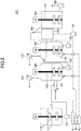
FIG.2] FIG. 2 is a schematic diagram showing an example of an apparatus for manufacturing a crumb used when manufacturing the crumb ofFIG. 1 . - [
FIG.3A] FIG. 3A is a schematic side view showing an example of the nozzle ofFIG. 2 . - [
FIG.3B] FIG. 3B is a schematic back view showing an example of the nozzle ofFIG. 2 . - Hereinafter, the embodiments for carrying out the present invention will be described.
-
FIG. 1 shows an example of crumb according to the present embodiment. - The crumb C contains rubber and has voids V formed therein.
- The volatile content of the crumb C is 5 to 50% by mass, and preferably 25 to 45% by mass. When the volatile content of the crumb C is less than 5% by mass, the crumb C deteriorates when the crumb C is dehydrated or when the dehydrated crumb C is dried. When the volatile content of the crumb C exceeds 50% by mass, clogging of a screen is generated, and the volatile content of a bale increases.
- The ratio of the surface area to the volume of crumb C is 0.04 mm-1 or more and preferably 0.05 mm-1 or more. When the ratio of the surface area to the volume of crumb C is less than 0.04 mm-1, the volatile content of a bale increases.
- The upper limit of the ratio of the surface area to the volume of crumb C is not particularly limited, but is preferably 0.20 mm-1 or less. When the ratio of the surface area to the volume of crumb C is 0.20 mm-1 or less, the toughness of crumb C is improved and the shape of crumb C is easily maintained during the transportation of crumb C.
- Here, the surface area of crumb C is the sum of the surface area of the voids V and the outer surface area of the crumb C.
- The rubber is not particularly limited. Examples of rubber include acrylic rubber, isoprene rubber, styrene/butadiene rubber (SBR), low cis butadiene rubber, high cis butadiene rubber, high trans butadiene rubber, styrene/isoprene rubber, butadiene/isoprene rubber, styrene/isoprene/butadiene rubber, ethylene/propylene/diene rubber, styrene/acrylonitrile/butadiene rubber, acrylonitrile/butadiene rubber, polyisoprene/SBR block copolymer, polystyrene/polybutadiene/polystyrene triblock copolymer, epichlorohydrin rubber, fluororubber, silicone rubber, ethylene/propylene rubber, urethane rubber, and the like.
- The rubber may have its terminal or molecular chain modified with at least one modifying group such as an amino group, a hydroxyl group, an alkoxysilyl group, a silanol group, and the like.
- A method of manufacturing a crumb C using the apparatus for manufacturing crumb 100 (see
FIG. 2 ) will be described. - First, a conventional solution polymerization method may be used to polymerize monomers serving as constituent units of rubber to prepare a rubber solution R.
- Next, the rubber solution R is transferred to the
rubber solution tank 110. Here, the viscosity may be adjusted by adding a solvent to the rubber solution R before the solution is transferred to therubber solution tank 110. Further, the rubber solution R transferred to therubber solution tank 110 is agitated by thestirrer 111 placed in therubber solution tank 110, as needed. - Next, the rubber solution R, pressurized steam S1, and hot water W are supplied to the
nozzle 121 provided on the side of thedesolvation tank 120. At this time, the rubber solution R is supplied from the bottom of therubber solution tank 110 by thepump 112. - An example of the
nozzle 121 is shown inFigs. 3A and 3B. Figs. 3A and 3B are a side view and a rear view, respectively. - The
nozzle 121 has a hotwater supply unit 121a on the bottom, has a pressurizedsteam supply unit 121b on the side, and has a rubbersolution supply unit 121c on the top. - Hot water W is supplied from the hot
water supply unit 121a to the inside of thenozzle 121 in the vertical direction (upward in the drawing) and then flows in the horizontal direction (rightward in the drawing). - In the present specification and claims, the horizontal direction is defined as a range of ±10° from the horizontal direction.
- Pressurized steam S1 is supplied from the pressurized
steam supply unit 121b to the hot water W flowing in the horizontal direction inside thenozzle 121 with respect to the flow direction of hot water W (rightward in the drawing). As a result, the moving speed of the generated crumbs C increases, and the crumbs C are less likely to collide with each other. As a result, agglomeration of the crumbs C can be suppressed. - The rubber solution R is supplied from the rubber
solution supply unit 121c into the hot water W flowing in the horizontal direction inside thenozzle 121 with respect to the direction perpendicular to the flowing direction of the hot water W (downward in the figure). As a result, the rubber solution R and the pressurized steam S1 are brought into contact with each other in the hot water W flowing in the horizontal direction to form a crumb C, and a slurry, in which the crumb C is dispersed, is generated. - In addition, the flow direction of the hot water W, the directions in which the pressurized steam S1 and the rubber solution R are supplied are not particularly limited, as long as the rubber solution R and the pressurized steam S1 are able to brought into contact each other in the hot water W flowing.
- For example, the pressurized steam S1 may be supplied in a direction of acute angle with respect to the direction of hot water W flowing.
- Further, the rubber solution R may be supplied in a direction of acute angle with respect to the direction of hot water W flowing. Thereby, the moving speed of the generated crumbs C are further increased, and the crumbs C are less likely to collide with each other. As a result, agglomeration of the crumbs C can be further suppressed.
- From the viewpoint of saving energy, when A represents a supply amount per unit time of the pressurized steam S1 [kg/h] and B represents a supply amount per unit time of the rubber solution R [t/h], the relation of A and B satisfies the following:


- The lower limit of the ratio A/B is not particularly limited, but is preferably 120 kg/t or more.
- Here, A is the mass per unit time of the pressurized steam S1 supplied into the hot water W flowing in the horizontal direction inside the
nozzle 121. Further, B is the volume per unit time of the rubber solution R supplied into the hot water W flowing in the horizontal direction inside thenozzle 121. - B is not particularly limited, but is preferably 10 to 100 t/h.
- The temperature of the pressurized steam S1 is not particularly limited, but is preferably 190 to 230°C.
- The pressure of the pressurized steam S1 is not particularly limited, but is preferably 0.6 to 3 MPa.
- The hot water W contains 3 to 35 ppm of dispersant, and preferably contains 10 to 30 ppm. When the content of the dispersant in the hot water W is less than 3 ppm, a particle size of crumb C becomes large. Due to this reason, the crumb C having an increased volatile content adheres to a screen, resulting in a generation of clogging of the screen. In addition, the crumb with increased volatile content adhere to each other, and the volatile content of the bale increases. On the other hand, when the content of the dispersant in the hot water W exceeds 35 ppm, the particle size of crumb C decreases. Therefore, when the ratio of the supply amount of the pressurized steam to the supply amount of the rubber solution is reduced, the crumb C having an increased volatile content adhere to a screen and clogging of a screen is generated. In addition, the crumb with increased volatile content adhere to each other, and the volatile content of the bale increases.
- The temperature of the hot water W is not particularly limited, but is preferably 70 to 120°C.
- Here, when the hot water W contains a dispersant having a cloud point, the temperature of the hot water W is preferably equal to or higher than the cloud point of the dispersant.
- As a dispersant, a nonionic surfactant, an anionic surfactant, a cationic surfactant, an amphoteric surfactant or the like can be used.
- Examples of the nonionic surfactant include block copolymers of two or more kinds of alkylene oxides such as oxyethyleneoxypropylene block copolymers; polyoxyalkylene ether compounds such as polyoxyethylene lauryl ether, polyoxyethylene cetyl ether, polyoxyethylene stearyl ether, polyoxyethylene oleyl ether, polyoxyethylene octylphenyl ether, and polyoxyethylene nonylphenyl ether is formed by polyadding alkylene oxide to higher alcohols having 5 to 50 carbon atoms such as lauryl alcohol, cetyl alcohol, stearyl alcohol, oleyl alcohol, and the like, to alkylphenols such as octylphenol, isooctylphenol, nonylphenol, and the like, and to alkylnaphthols such as butylnaphthol, octylnaphthol, and the like; polyoxyalkylene glycol fatty acid ester compounds such as polyoxyethylene glycol monolaurate, polyoxyethylene glycol monopalmitate, polyethylene glycol monostearate, polyethylene glycol distearate, polyethylene glycol monooleate, and the like formed by polyadding alkylene oxide to higher fatty acids having 5 to 50 carbon atoms such as lauric acid, palmitic acid, stearic acid, oleic acid, and the like; polyhydric alcohol fatty acid ester compounds such as glyceryl monostearate, glyceryl monooleate, sorbitan monolaurate, sorbitan monopalmitate, sorbitan monostearate, sorbitan distearate, sorbitan tristearate, sorbitan monooleate, sorbitan dioleate, mannitan monolaurate, mannitan monostearate, mannitan distearate, mannitan monooleate, hexitan monolaurate, hexitan monopalmitate, hexitan monostearate, hexitan distearate, hexitan tristearate, hexitan monooleate, hexitan dioleate, and the like, that are esters of a polyhydric alcohol having 3 or more hydroxyl groups in the molecules such as glycerin, pentaerythritol, sorbitan, mannitan, hexitan, and polycondensates thereof with higher fatty acids having 5 to 50 carbon atoms; polyoxyalkylene polyhydric alcohol fatty acid ester compounds such as polyoxyethylene sorbitan monolaurate, polyoxyethylene sorbitan monostearate, polyoxyethylene sorbitan distearate, polyoxyethylene sorbitan monooleate, polyoxyethylene mannitan monopalmitate, polyoxyethylene mannitan monostearate, polyoxyethylene mannitan monooleate, polyoxyethylene hexitan monolaurate, polyoxyethylene hexitan monostearate, and the like formed by polyadding alkylene oxide to the polyhydric alcohol fatty acid ester compounds; polyoxyalkylene alkylamine compounds such as polyoxyethylene stearylamine, polyoxyethylene oleylamine, and the like; and alkylalkanolamide compounds.
- Among these, polyoxyalkylene compounds such as block copolymers of two or more kinds of alkylene oxides, polyoxyalkylene ether compounds, polyoxyalkylene glycol fatty acid ester compounds, polyoxyalkylene polyhydric alcohol fatty acid ester compounds, and polyoxyalkylene alkylamine compounds are preferably used; and oxyethyleneoxypropylene block copolymer, polyoxyethylene lauryl ether, polyoxyethylene stearyl ether, polyoxyethylene nonylphenyl ether, polyethylene glycol monostearate, polyoxyethylene sorbitan monostearate, and polyoxyethylene stearylamine are particularly preferably used.
- Examples of the anionic surfactant include carboxylates such as aliphatic monocarboxylate, polyoxyethylene alkylether carboxylate, N-acyl sarcosine salt, N-acyl glutamate, and the like; sulfonates such as dialkyl sulfosuccinate, alkyl sulfonate, α-olefin sulfonate, linear alkyl benzene sulfonate, branched alkyl benzene sulfonates, naphthalene sulfonate-formaldehyde condensate, alkyl naphthalene sulfonate, N-methyl-N-acyl taurate, and the like; sulfates such as alkyl sulfate, polyoxyalkyl ether sulfate, fat and oil sulfate, and the like; phosphates such as alkyl phosphate, polyoxyethylene alkyl ether phosphate, polyoxyethylene alkylphenylether phosphate, and the like.
- Examples of the cationic surfactant include monoalkylamine salt, dialkylamine salt, trialkylamine salt, alkyltrimethylammonium chloride, alkyltrimethylammonium bromide, alkyltrimethylammonium iodide, dialkyldimethylammonium chloride salt, dialkyldimethylammnonium bromide salt, dialkyldimethylammonium iodide salt, alkylbenzalkonium chloride, and the like.
- Examples of the amphoteric surfactant include alkyldimethylamino acetic acid betaine, alkyldimethyl acetic acid betaine, alkyldimethyl carboxymethyl betaine, alkyldimethyl carboxymethylene ammonium betaine, alkyldimethyl ammonioacetate, fatty acid amidepropyl dimethylamino acid betaine, alkyloylamidepropyl dimethylglycine, alkyloylamidopropyldimethyl ammonioacetate, 2-alkyl-1-(2-hydroxyethyl) imidazolinium-1-acetate, alkyldiaminoethylglycine, dialkyldiaminoethylglycine, alkyldimethylamineoxide, and the like.
- A dispersant may be used alone or in combination of two or more types.
- The content of the rubber in the rubber solution R is not particularly limited, but is preferably 10 to 50% by mass.
- Next, the slurry in which the crumb C is dispersed, which is generated in the
nozzle 121, is transferred to thedesolvation tank 120. At this time, the steam S2 is supplied vertically (upward in the drawing) from the bottom of thedesolvation tank 120, while stirring the slurry transferred to thedesolvation tank 120 using thestirrer 122. Then, the slurry is desolvated by a steam stripping method. As a result, a part of the volatile organic compounds (solvents, unreacted monomers, etc.) contained in the slurry, in which the crumb C is dispersed, evaporates. - Here, the volatile organic compound that has evaporated by desolvation is condensed in the
condenser 124, and then the solvent is recovered and reused as needed. - The temperature of steam S2 is not particularly limited, but is preferably 100 to 190°C.
- The pressure of steam S2 is not particularly limited, but is preferably 0.1 to 1 MPa.
- Next, the desolvated slurry is transferred from the bottom of the
desolvation tank 120 to the bottom of thedesolvation tank 130 by thepump 112. At this time, the steam S2 is supplied vertically (upward in the figure) from the bottom of thedesolvation tank 130, while stirring the slurry transferred to thedesolvation tank 130 using thestirrer 131. The slurry is then desolvated by a steam stripping method. As a result, the rest of the volatile organic compounds contained in the slurry, in which the crumbs C are dispersed, evaporates, and a hot water slurry in which the crumb C is dispersed is generated. - Here, the volatile organic compound that has evaporated by desolvation is condensed in the
condenser 133, and then the solvent is recovered and reused as needed. - Note that the number of desolvation tanks is not limited to two. The number of desolvation tanks can be appropriately changed to a number that can sufficiently remove the volatile organic compounds contained in the slurry in which the crumb C is dispersed.
- Next, the hot water slurry is transferred from the bottom of the
desolvation tank 130 to thescreen 140 by thepump 132, and the hot water slurry is separated into serum water (hot water) and crumbs C. As a result, the serum water is collected in theserum water tank 150 and the crumbs C are collected in thecrumb tank 160. - Here, the serum water collected in the
serum water tank 150 is transferred from the bottom of theserum water tank 150 using thepump 151 as needed. Then, the serum water is mixed with the hot water W and reused. - The inclination angle of the
screen 140 is not particularly limited, but is preferably 30 to 75°. - Further, the crumb C collected in the
crumb tank 160 is stirred by astirrer 161 as needed. Then, the crumb C is transferred from the side of thecrumb tank 160 by thepump 162, and the crumb C is used for manufacturing a bale. - A bale includes rubber and can be produced by a known method using the crumbs C produced by the method of manufacturing crumbs of the present embodiment.
- For example, the crumbs C are dehydrated, dried, and then molded using a mold having a predetermined shape to produce a bale.
- Here, the crumb C may be crushed and then dehydrated.
- As a dehydrator for dehydrating the crumb C, for example, a screw press type dehydrator or the like can be used.
- As a dryer for drying the dehydrated crumb C, for example, an expansion type extrusion dryer, a vibration dryer or the like can be used.
- As a molding machine for molding the dried crumb C, a known molding machine can be used.
- Examples of the present invention will be described below, but the present invention is not limited to the described examples. In addition, "part" and "%" are based on mass unless otherwise specified.
- The crumbs and the bales produced by the method described below were evaluated by the following.
- The crumbs that were collected on the screen placed in front of the crumb tank were classified using sieves with mesh sizes of 16 mm, 8 mm, 4.75 mm, 3.35 mm, 2.36 mm, 1.7 mm, 1.4 mm, and 0.71 mm in according with JIS Z8801. The median diameter D50 on mass bases of the crumbs were calculated.
- A three-dimensional image of the crumbs collected by the screen provided in front of the crumb tank was photographed by a three-dimensional X-ray CT apparatus TDM1000-IS (manufactured by Yamato Scientific Co., Ltd.) under the following conditions.
-
- Target: W
- Tube voltage: 35kV
- Tube current: 70 µA
- Shooting condition: 360° rotation
- Next, the surface area of voids (the inner surface area of the crumb), the outer surface area of the crumb, and the volume of the crumb was calculated from the three-dimensional images of the crumb obtained by binarizing into the structure and the space.
- Finally, the ratio of surface area to the volume of crumb was calculated by the following formula:

- The amount of residual solvent in the crumbs or bales was measured by headspace gas chromatography in accordance with ASTM D1416 Standard Test Methods for Rubber from Synthetic Sources-Chemical Analysis. Specifically, after a sample was put in a vial, the sample was kept at 160°C for 30 minutes to quantify the amount of the solvent in the volatile content to determine the amount of the residual solvent. An FID detector was used as the detector.
- The volatile content of crumbs or bales was measured in accordance with the method A described in JIS H6238-2, Raw material rubber-Method of determining volatile content (quantitative amount) - Part 2 The automatic infrared dry thermogravimetric method.
- The clogging of the screen, which was placed in front of the crumb tank, was visually evaluated.
- 18.8t of a mixed solvent of cyclohexane and butane in a mass ratio of 70:30 and 2.5t of 1,3-butadiene were charged into a reaction vessel equipped with a jacket of approximately 47 m3, a cooler, and a stirrer. Then, the mixture was stirred and mixed. Next, 30 mol of n-butyllithium was added while stirring the mixed solution in the reaction vessel, and then a polymerization was started at 50°C. Here, 1,3-butadiene used is the one obtained by removing 4-t-butylcatechol (TBC) as a polymerization inhibitor. After 40 minutes from the start of the polymerization, 2.5t of 1,3-butadiene was continuously added over 30 minutes when the temperature of the mixed solution reached 80°C. Next, when the polymerization conversion rate exceeded 99%, 3 mol of tin tetrachloride was added and stirred for 5 minutes, then 16 mol of N-phenyl-2-pyrrolidone was added and reacted for 5 minutes to obtain a polymerization solution.
- The polymerization solution was transferred from the reaction vessel to the
rubber solution tank 110 of the apparatus for manufacturing crumb 100 (seeFIG. 2 ). Here, 30 mol of methanol was added to stop the polymerization while transferring the polymerization solution, and then 0.3 phr of Irganox 1520L (manufactured by BASF) as a stabilizer was added to obtain a butadiene rubber solution as a rubber solution R. The content of a butadiene rubber in the rubber solution R was 21% by mass. - After the rubber solution R was transferred to the
rubber solution tank 110, the rubber solution R was stirred using thestirrer 111 and stored in a homogenized state. - Here, a small amount of the rubber solution R was sampled, solidified, and then vacuum dried to obtain a butadiene rubber. The 1,2-bonding amount of the butadiene rubber was 9% when measured by FT-IR (solution method). The Mooney viscosity ML1+4 (100°C) of the butadiene rubber was measured and the viscosity thereof was 50.
- Crumbs were produced using the apparatus for manufacturing crumb 100 (see
FIG. 2 ). - First, the pressurized steam S1, the rubber solution R, and hot water W at 80°C were supplied to the
nozzle 121 of thedesolvation tank 120. Specifically, both of the rubber solution R and the pressurized steam S1 at 1.09 MPa and 190°C were supplied in the vertical direction and the horizontal direction, respectively, into the hot water W flowing in the horizontal direction. Then, the rubber solution R and the pressurized steam S1 were brought into contact to obtain a slurry in which crumb C was dispersed (seeFIGS. 3A and 3B ). Here, the supply amount A of a pressurized steam S1 per unit time [kg/h], the supply amount B of a rubber solution R per unit time [t/h], and the supply amount of hot water W per unit time [t/h], the content of a dispersant in hot water W [ppm] were set to the values described in production conditions of crumbs (see Table 1). As the dispersant, a polyoxyethylene-polyoxypropylene condensate having a cloud point of 58°C was used. - Next, after transferring the slurry in which the crumb C was dispersed to the
desolvation tank 120, the steam S2 at 0.3 MPa and 180°C was supplied, and a part of the solvent was evaporated by a steam stripping method. - Next, after transferring the slurry in which a part of the solvent is evaporated to the
desolvation tank 130, the steam S2 at 0.3 MPa and 180°C was supplied. The remaining part of the solvent was evaporated by a steam stripping method to produce a hot water slurry in which the crumb C was dispersed. - Next, the hot water slurry in which the crumb C was dispersed was separated using a
plain weave screen 140 with an opening of 0.5 mm provided at an inclination angle of 60°. As a result, the serum water was collected in theserum water tank 150, and the crumb C was collected in thecrumb tank 160. - The crumb C collected in the
crumb tank 160 was transferred to a plain weave vibrating screen with an opening of 0.5 mm provided at an inclination angle of 0°. Then, the crumb C was crushed and then dehydrated by a screw press type dehydrator. - Next, the dehydrated crumb C was extruded at 70 rpm and dried using an expansion type extruder having an inner diameter of 14 inches. Here, a die having 60 round-shaped nozzles having a diameter of 9 mm was provided at the outlet of the expansion type extrusion dryer, and the extruded crumb C was cut by a cutter rotating at 400 rpm.
- Next, the shredded crumb C was dried by a vibration dryer. At this time, the residence time in the vibration dryer was adjusted to be about 5 minutes. The vibration dryer was divided into seven sections, and the temperatures of the seven sections were set to 80°C, 100°C, 100°C, 100°C, 90°C, 80°C, and 40°C in the order in which the shredded crumb C was conveyed.
- Next, the dried crumb C was molded into a bale using a rectangular parallelepiped mold.
- Table 1 shows the evaluation results of the properties of crumbs C, the production conditions of the crumbs C, and the properties of the bales.

- From Table 1, Examples 1 to 4 showed that clogging of the
screen 140 was suppressed, and the volatile contents of the bales were decreased when the ratio A/B was lowered to 143 to 243 kg/t. - In contrast, Comparative Example 1 showed that the ratio A/B was 429 kg/t, in which the ratio was not lowered. The ratio of the surface area to the volume of the crumb was 0.012 mm-1 and the volatile content was 55.6% by mass, because the dispersant was not added to the hot water W. As a result, the clogging of the
screen 140 was generated, and the volatile content of the bale increased. - Comparative Example 2 showed that the ratio A/B was 329 kg/t, in which the ratio was not lowered. The ratio of the surface area to the volume of the crumb was 0.039 mm-1 and the volatile content was 51.0% by mass, because the dispersant was not added to the hot water W. As a result, the clogging of the
screen 140 was generated, and the volatile content of the bale increased. - Comparative Example 3 showed that the ratio A/B was lowered to 243, but the content of the dispersant in the hot water W was 50 ppm. Accordingly, the ratio of the surface area to the volume of crumb was 0.036 mm-1, and the volatile content was 60.5% by mass. As a result, the clogging of the
screen 140 was generated and the volatile content of the bale increased. - Although the embodiments of the present invention have been described above by way of examples, the present invention is not limited to specific embodiments and examples, and various modifications and alterations may be made within the scope of the invention described in the claims.
- This international application is based on and claims priority of Japanese Patent Application No.
2018-062949 filed March 28, 2018 -
- 100:
- Apparatus for manufacturing crumb
- 110:
- Rubber solution tank
- 111, 122, 131, 161:
- Stirrers
- 112, 123, 132, 151, 162:
- Pumps
- 120, 130:
- Desolvation tanks
- 121:
- Nozzle
- 121a:
- Hot water supply unit
- 121b:
- Pressurized steam supply unit
- 121c:
- Rubber solution supply unit
- 124, 133:
- Condensers
- 140:
- Screen
- 150:
- Serum water tank
- 160:
- Crumb tank
- C:
- Crumb
- V:
- Void
- R:
- Rubber solution
- S1:
- Pressurized steam
- S2:
- Steam
- W:
- Hot water
Claims (4)
- A crumb comprising:rubber;wherein a volatile content of the crumb is 5 to 50% by mass, and a ratio of a surface area of the crumb to a volume of the crumb is 0.04 mm-1 or more.
- A method of manufacturing crumbs comprising:supplying a rubber solution and a pressurized steam into hot water flowing in a predetermined direction and bringing the rubber solution and the pressurized steam into contact with each other,wherein when A represents a supply amount per unit time [kg/h] of the pressurized steam and B represents a supply amount per unit time [t/h] of the rubber solution, a relation of A and B satisfies the following:
 the hot water contains 3 to 35 ppm of a dispersant.
 - The method of manufacturing crumbs according to claim 2, wherein
flowing the hot water in a horizontal direction;
supplying the rubber solution in the orthogonal direction or acute direction with respect to the flow direction of the hot water; and
supplying the pressurized steam into the flow direction of the hot water. - A method of manufacturing a bale comprising, manufacturing the crumbs by applying the method of manufacturing the crumbs of claim 2 or 3.
Applications Claiming Priority (2)
| Application Number | Priority Date | Filing Date | Title |
|---|---|---|---|
| JP2018062949 | 2018-03-28 | ||
| PCT/JP2019/004035 WO2019187650A1 (en) | 2018-03-28 | 2019-02-05 | Crumbs, production method for same, and production method for bale |
Publications (2)
| Publication Number | Publication Date |
|---|---|
| EP3778718A1 true EP3778718A1 (en) | 2021-02-17 |
| EP3778718A4 EP3778718A4 (en) | 2021-11-17 |
Family
ID=68058747
Family Applications (1)
| Application Number | Title | Priority Date | Filing Date |
|---|---|---|---|
| EP19775073.0A Pending EP3778718A4 (en) | 2018-03-28 | 2019-02-05 | PELLETS, RELATED MANUFACTURING PROCESS, AND BALL MANUFACTURING PROCESS |
Country Status (4)
| Country | Link |
|---|---|
| EP (1) | EP3778718A4 (en) |
| JP (1) | JP7264156B2 (en) |
| SG (1) | SG11202008991PA (en) |
| WO (1) | WO2019187650A1 (en) |
Family Cites Families (23)
| Publication number | Priority date | Publication date | Assignee | Title |
|---|---|---|---|---|
| US3751402A (en) * | 1969-04-14 | 1973-08-07 | Nat Distillers Chem Corp | Process for the recovery of rubbery polymers in crumb form |
| JPS541741B1 (en) * | 1969-08-13 | 1979-01-29 | ||
| JPS5522489B2 (en) * | 1972-09-28 | 1980-06-17 | ||
| JPS6010041B2 (en) * | 1975-12-19 | 1985-03-14 | 旭化成株式会社 | How to obtain rubbery polymers |
| JPS5859201A (en) * | 1981-10-06 | 1983-04-08 | Ube Ind Ltd | Treatment apparatus of polymer solution |
| JPS5861122A (en) * | 1981-10-08 | 1983-04-12 | Ube Ind Ltd | Method for separating rubbery polymers from organic solvents |
| JP2556066B2 (en) * | 1987-11-09 | 1996-11-20 | 日本合成ゴム株式会社 | Recovery method of rubbery polymer |
| CA2171045C (en) | 1995-03-06 | 2002-08-13 | Manabu Kusano | Microporous crumbs of hydrogenated block copolymers and process for producing the same |
| JPH1017611A (en) * | 1996-06-28 | 1998-01-20 | Nippon Zeon Co Ltd | Method for producing block copolymer |
| JP3575228B2 (en) * | 1997-05-28 | 2004-10-13 | Jsr株式会社 | Method for obtaining rubbery polymer, and rubbery polymer |
| ES2267575T3 (en) * | 1999-10-28 | 2007-03-16 | Asahi Kasei Kabushiki Kaisha | PROCEDURE FOR THE ELIMINATION OF A HYDROCARBON SOLVENT FROM A HYDROGEN BLOCK SOLUTION IN A HYDROCARBON SOLVENT. |
| JP2001226427A (en) * | 1999-11-05 | 2001-08-21 | Ube Ind Ltd | Method for removing volatile substances from elastomer |
| JP3858608B2 (en) | 2001-02-21 | 2006-12-20 | 宇部興産株式会社 | Method for removing volatile substances in elastomer |
| JP4730499B2 (en) * | 2001-07-30 | 2011-07-20 | Jsr株式会社 | Polymer recovery method |
| JP3910413B2 (en) * | 2001-11-14 | 2007-04-25 | ティーエスアールシー コーポレイション | Rubber particle grinding apparatus and method |
| CA2490770A1 (en) * | 2002-07-03 | 2004-01-22 | Jsr Corporation | Method of removing solvent from polymer solution and solvent removing apparatus |
| JPWO2007034660A1 (en) * | 2005-09-20 | 2009-03-19 | 株式会社カネカ | Method for producing resin powder |
| JP2008239642A (en) | 2007-03-23 | 2008-10-09 | Kaneka Corp | Method for producing resin granule |
| WO2013080969A1 (en) * | 2011-11-28 | 2013-06-06 | 旭化成ケミカルズ株式会社 | Steam stripping device and steam-stripping finishing method using same |
| SG11201405818SA (en) * | 2012-03-26 | 2014-11-27 | Asahi Kasei Chemicals Corp | Method for producing rubber-like polymer |
| JP6123415B2 (en) | 2013-03-27 | 2017-05-10 | 三菱化学株式会社 | Method for recovering hydrogenated block copolymer and resin composition |
| ITUB20159578A1 (en) * | 2015-12-14 | 2017-06-14 | Versalis Spa | Procedure for the separation of non-Hevea natural rubber in solid form from solutions that include it. |
| JP2018062949A (en) | 2016-10-11 | 2018-04-19 | 株式会社オティックス | Differential device |
-
2019
- 2019-02-05 EP EP19775073.0A patent/EP3778718A4/en active Pending
- 2019-02-05 SG SG11202008991PA patent/SG11202008991PA/en unknown
- 2019-02-05 WO PCT/JP2019/004035 patent/WO2019187650A1/en not_active Ceased
- 2019-02-05 JP JP2020510351A patent/JP7264156B2/en active Active
Also Published As
| Publication number | Publication date |
|---|---|
| JPWO2019187650A1 (en) | 2021-04-01 |
| JP7264156B2 (en) | 2023-04-25 |
| SG11202008991PA (en) | 2020-10-29 |
| EP3778718A4 (en) | 2021-11-17 |
| WO2019187650A1 (en) | 2019-10-03 |
Similar Documents
| Publication | Publication Date | Title |
|---|---|---|
| TWI626251B (en) | Polypropylene with narrow molecular weight distribution and preparation method thereof | |
| US4472559A (en) | Process for producing polybutadiene rubber with enhanced mechanical strength | |
| EP3873979B1 (en) | Upgraded recycled polyethylene polypropylene blend | |
| EP2676968A1 (en) | High Mooney NdBR with Mooney jump | |
| FI99248C (en) | Amorphous elastomeric propylene homopolymers | |
| Burfield et al. | Cold crystallization of natural rubber and its synthetic analogues: The influence of chain microstructure | |
| CN1043999C (en) | Bulk polymerization process of butadienes | |
| EP3778718A1 (en) | Crumbs, production method for same, and production method for bale | |
| CN102952225A (en) | Suspension polymerization method for reducing polyvinyl chloride resin fisheyes | |
| EP3778720A1 (en) | Production method for crumbs and production method for bale | |
| Hu et al. | Synthesis and characterization of biodegradable and biocompatible amphiphilic block copolymers bearing pendant amino acid residues | |
| JP2005510554A (en) | Neutral carbonated alkaline earth metal carboxylates | |
| CN113024793B (en) | Method for synthesizing polyoxyethylene | |
| RU2073023C1 (en) | Process for preparing synthetic butadiene-styrene rubbers | |
| JP6646437B2 (en) | Method for producing conjugated diene polymer | |
| US20090275676A1 (en) | Process for Producing Particulate Resin | |
| WO2020203811A1 (en) | Polymer solution desolvation method | |
| EP2980083A1 (en) | Method for producing glycolide | |
| CN105777945B (en) | A kind of method of polyolefin glue cohesion | |
| JP2001129307A (en) | Defoaming agent composition | |
| JPH0237927B2 (en) | HOKYOHORIBUTA JENNOSEIZOHO | |
| RU2156263C1 (en) | Butyl rubber stabilization process | |
| KR20160037692A (en) | Method for preparing polyamide | |
| DE1800935A1 (en) | Purification step in a continuous alfin polymerisation | |
| CN1216770A (en) | Process for producing a composition comprising a diluent and a copolymer and said composition |
Legal Events
| Date | Code | Title | Description |
|---|---|---|---|
| STAA | Information on the status of an ep patent application or granted ep patent |
Free format text: STATUS: THE INTERNATIONAL PUBLICATION HAS BEEN MADE |
|
| PUAI | Public reference made under article 153(3) epc to a published international application that has entered the european phase |
Free format text: ORIGINAL CODE: 0009012 |
|
| STAA | Information on the status of an ep patent application or granted ep patent |
Free format text: STATUS: REQUEST FOR EXAMINATION WAS MADE |
|
| 17P | Request for examination filed |
Effective date: 20200909 |
|
| AK | Designated contracting states |
Kind code of ref document: A1 Designated state(s): AL AT BE BG CH CY CZ DE DK EE ES FI FR GB GR HR HU IE IS IT LI LT LU LV MC MK MT NL NO PL PT RO RS SE SI SK SM TR |
|
| AX | Request for extension of the european patent |
Extension state: BA ME |
|
| DAV | Request for validation of the european patent (deleted) | ||
| DAX | Request for extension of the european patent (deleted) | ||
| REG | Reference to a national code |
Ref country code: DE Ref legal event code: R079 Free format text: PREVIOUS MAIN CLASS: C08J0003120000 Ipc: C08L0009000000 |
|
| A4 | Supplementary search report drawn up and despatched |
Effective date: 20211014 |
|
| RIC1 | Information provided on ipc code assigned before grant |
Ipc: C08J 3/14 20060101ALI20211008BHEP Ipc: C08F 6/00 20060101ALI20211008BHEP Ipc: C08F 6/24 20060101ALI20211008BHEP Ipc: C08F 6/12 20060101ALI20211008BHEP Ipc: C08C 2/06 20060101ALI20211008BHEP Ipc: C08J 3/12 20060101ALI20211008BHEP Ipc: C08L 21/00 20060101ALI20211008BHEP Ipc: C08L 9/00 20060101AFI20211008BHEP |
|
| TPAC | Observations filed by third parties |
Free format text: ORIGINAL CODE: EPIDOSNTIPA |
|
| STAA | Information on the status of an ep patent application or granted ep patent |
Free format text: STATUS: EXAMINATION IS IN PROGRESS |
|
| 17Q | First examination report despatched |
Effective date: 20240729 |
|
| GRAP | Despatch of communication of intention to grant a patent |
Free format text: ORIGINAL CODE: EPIDOSNIGR1 |
|
| STAA | Information on the status of an ep patent application or granted ep patent |
Free format text: STATUS: GRANT OF PATENT IS INTENDED |
|
| INTG | Intention to grant announced |
Effective date: 20260327 |