EP3778175A1 - Method for manufacturing foam molded body - Google Patents
Method for manufacturing foam molded body Download PDFInfo
- Publication number
- EP3778175A1 EP3778175A1 EP19778168.5A EP19778168A EP3778175A1 EP 3778175 A1 EP3778175 A1 EP 3778175A1 EP 19778168 A EP19778168 A EP 19778168A EP 3778175 A1 EP3778175 A1 EP 3778175A1
- Authority
- EP
- European Patent Office
- Prior art keywords
- molded body
- foam
- gas
- foam molded
- foaming gas
- Prior art date
- Legal status (The legal status is an assumption and is not a legal conclusion. Google has not performed a legal analysis and makes no representation as to the accuracy of the status listed.)
- Granted
Links
Images


Classifications
-
- C—CHEMISTRY; METALLURGY
- C08—ORGANIC MACROMOLECULAR COMPOUNDS; THEIR PREPARATION OR CHEMICAL WORKING-UP; COMPOSITIONS BASED THEREON
- C08J—WORKING-UP; GENERAL PROCESSES OF COMPOUNDING; AFTER-TREATMENT NOT COVERED BY SUBCLASSES C08B, C08C, C08F, C08G or C08H
- C08J9/00—Working-up of macromolecular substances to porous or cellular articles or materials; After-treatment thereof
- C08J9/04—Working-up of macromolecular substances to porous or cellular articles or materials; After-treatment thereof using blowing gases generated by a previously added blowing agent
- C08J9/12—Working-up of macromolecular substances to porous or cellular articles or materials; After-treatment thereof using blowing gases generated by a previously added blowing agent by a physical blowing agent
- C08J9/122—Hydrogen, oxygen, CO2, nitrogen or noble gases
-
- B—PERFORMING OPERATIONS; TRANSPORTING
- B29—WORKING OF PLASTICS; WORKING OF SUBSTANCES IN A PLASTIC STATE IN GENERAL
- B29C—SHAPING OR JOINING OF PLASTICS; SHAPING OF MATERIAL IN A PLASTIC STATE, NOT OTHERWISE PROVIDED FOR; AFTER-TREATMENT OF THE SHAPED PRODUCTS, e.g. REPAIRING
- B29C44/00—Shaping by internal pressure generated in the material, e.g. swelling or foaming ; Producing porous or cellular expanded plastics articles
- B29C44/34—Auxiliary operations
- B29C44/36—Feeding the material to be shaped
- B29C44/46—Feeding the material to be shaped into an open space or onto moving surfaces, i.e. to make articles of indefinite length
- B29C44/50—Feeding the material to be shaped into an open space or onto moving surfaces, i.e. to make articles of indefinite length using pressure difference, e.g. by extrusion or by spraying
-
- B—PERFORMING OPERATIONS; TRANSPORTING
- B29—WORKING OF PLASTICS; WORKING OF SUBSTANCES IN A PLASTIC STATE IN GENERAL
- B29B—PREPARATION OR PRETREATMENT OF THE MATERIAL TO BE SHAPED; MAKING GRANULES OR PREFORMS; RECOVERY OF PLASTICS OR OTHER CONSTITUENTS OF WASTE MATERIAL CONTAINING PLASTICS
- B29B11/00—Making preforms
- B29B11/06—Making preforms by moulding the material
- B29B11/10—Extrusion moulding
-
- B—PERFORMING OPERATIONS; TRANSPORTING
- B29—WORKING OF PLASTICS; WORKING OF SUBSTANCES IN A PLASTIC STATE IN GENERAL
- B29C—SHAPING OR JOINING OF PLASTICS; SHAPING OF MATERIAL IN A PLASTIC STATE, NOT OTHERWISE PROVIDED FOR; AFTER-TREATMENT OF THE SHAPED PRODUCTS, e.g. REPAIRING
- B29C44/00—Shaping by internal pressure generated in the material, e.g. swelling or foaming ; Producing porous or cellular expanded plastics articles
- B29C44/34—Auxiliary operations
- B29C44/3442—Mixing, kneading or conveying the foamable material
- B29C44/3446—Feeding the blowing agent
-
- B—PERFORMING OPERATIONS; TRANSPORTING
- B29—WORKING OF PLASTICS; WORKING OF SUBSTANCES IN A PLASTIC STATE IN GENERAL
- B29C—SHAPING OR JOINING OF PLASTICS; SHAPING OF MATERIAL IN A PLASTIC STATE, NOT OTHERWISE PROVIDED FOR; AFTER-TREATMENT OF THE SHAPED PRODUCTS, e.g. REPAIRING
- B29C44/00—Shaping by internal pressure generated in the material, e.g. swelling or foaming ; Producing porous or cellular expanded plastics articles
- B29C44/34—Auxiliary operations
- B29C44/36—Feeding the material to be shaped
- B29C44/46—Feeding the material to be shaped into an open space or onto moving surfaces, i.e. to make articles of indefinite length
- B29C44/50—Feeding the material to be shaped into an open space or onto moving surfaces, i.e. to make articles of indefinite length using pressure difference, e.g. by extrusion or by spraying
- B29C44/507—Feeding the material to be shaped into an open space or onto moving surfaces, i.e. to make articles of indefinite length using pressure difference, e.g. by extrusion or by spraying extruding the compound through an annular die
-
- B—PERFORMING OPERATIONS; TRANSPORTING
- B29—WORKING OF PLASTICS; WORKING OF SUBSTANCES IN A PLASTIC STATE IN GENERAL
- B29C—SHAPING OR JOINING OF PLASTICS; SHAPING OF MATERIAL IN A PLASTIC STATE, NOT OTHERWISE PROVIDED FOR; AFTER-TREATMENT OF THE SHAPED PRODUCTS, e.g. REPAIRING
- B29C44/00—Shaping by internal pressure generated in the material, e.g. swelling or foaming ; Producing porous or cellular expanded plastics articles
- B29C44/34—Auxiliary operations
- B29C44/56—After-treatment of articles, e.g. for altering the shape
-
- B—PERFORMING OPERATIONS; TRANSPORTING
- B29—WORKING OF PLASTICS; WORKING OF SUBSTANCES IN A PLASTIC STATE IN GENERAL
- B29C—SHAPING OR JOINING OF PLASTICS; SHAPING OF MATERIAL IN A PLASTIC STATE, NOT OTHERWISE PROVIDED FOR; AFTER-TREATMENT OF THE SHAPED PRODUCTS, e.g. REPAIRING
- B29C49/00—Blow-moulding, i.e. blowing a preform or parison to a desired shape within a mould; Apparatus therefor
- B29C49/02—Combined blow-moulding and manufacture of the preform or the parison
- B29C49/04—Extrusion blow-moulding
-
- B—PERFORMING OPERATIONS; TRANSPORTING
- B29—WORKING OF PLASTICS; WORKING OF SUBSTANCES IN A PLASTIC STATE IN GENERAL
- B29C—SHAPING OR JOINING OF PLASTICS; SHAPING OF MATERIAL IN A PLASTIC STATE, NOT OTHERWISE PROVIDED FOR; AFTER-TREATMENT OF THE SHAPED PRODUCTS, e.g. REPAIRING
- B29C67/00—Shaping techniques not covered by groups B29C39/00 - B29C65/00, B29C70/00 or B29C73/00
- B29C67/20—Shaping techniques not covered by groups B29C39/00 - B29C65/00, B29C70/00 or B29C73/00 for porous or cellular articles, e.g. of foam plastics, coarse-pored
-
- C—CHEMISTRY; METALLURGY
- C08—ORGANIC MACROMOLECULAR COMPOUNDS; THEIR PREPARATION OR CHEMICAL WORKING-UP; COMPOSITIONS BASED THEREON
- C08J—WORKING-UP; GENERAL PROCESSES OF COMPOUNDING; AFTER-TREATMENT NOT COVERED BY SUBCLASSES C08B, C08C, C08F, C08G or C08H
- C08J9/00—Working-up of macromolecular substances to porous or cellular articles or materials; After-treatment thereof
- C08J9/04—Working-up of macromolecular substances to porous or cellular articles or materials; After-treatment thereof using blowing gases generated by a previously added blowing agent
- C08J9/12—Working-up of macromolecular substances to porous or cellular articles or materials; After-treatment thereof using blowing gases generated by a previously added blowing agent by a physical blowing agent
-
- B—PERFORMING OPERATIONS; TRANSPORTING
- B29—WORKING OF PLASTICS; WORKING OF SUBSTANCES IN A PLASTIC STATE IN GENERAL
- B29K—INDEXING SCHEME ASSOCIATED WITH SUBCLASSES B29B, B29C OR B29D, RELATING TO MOULDING MATERIALS OR TO MATERIALS FOR MOULDS, REINFORCEMENTS, FILLERS OR PREFORMED PARTS, e.g. INSERTS
- B29K2023/00—Use of polyalkenes or derivatives thereof as moulding material
- B29K2023/10—Polymers of propylene
- B29K2023/12—PP, i.e. polypropylene
-
- C—CHEMISTRY; METALLURGY
- C08—ORGANIC MACROMOLECULAR COMPOUNDS; THEIR PREPARATION OR CHEMICAL WORKING-UP; COMPOSITIONS BASED THEREON
- C08J—WORKING-UP; GENERAL PROCESSES OF COMPOUNDING; AFTER-TREATMENT NOT COVERED BY SUBCLASSES C08B, C08C, C08F, C08G or C08H
- C08J2201/00—Foams characterised by the foaming process
- C08J2201/02—Foams characterised by the foaming process characterised by mechanical pre- or post-treatments
- C08J2201/024—Preparation or use of a blowing agent concentrate, i.e. masterbatch in a foamable composition
-
- C—CHEMISTRY; METALLURGY
- C08—ORGANIC MACROMOLECULAR COMPOUNDS; THEIR PREPARATION OR CHEMICAL WORKING-UP; COMPOSITIONS BASED THEREON
- C08J—WORKING-UP; GENERAL PROCESSES OF COMPOUNDING; AFTER-TREATMENT NOT COVERED BY SUBCLASSES C08B, C08C, C08F, C08G or C08H
- C08J2201/00—Foams characterised by the foaming process
- C08J2201/02—Foams characterised by the foaming process characterised by mechanical pre- or post-treatments
- C08J2201/03—Extrusion of the foamable blend
-
- C—CHEMISTRY; METALLURGY
- C08—ORGANIC MACROMOLECULAR COMPOUNDS; THEIR PREPARATION OR CHEMICAL WORKING-UP; COMPOSITIONS BASED THEREON
- C08J—WORKING-UP; GENERAL PROCESSES OF COMPOUNDING; AFTER-TREATMENT NOT COVERED BY SUBCLASSES C08B, C08C, C08F, C08G or C08H
- C08J2203/00—Foams characterized by the expanding agent
- C08J2203/06—CO2, N2 or noble gases
-
- C—CHEMISTRY; METALLURGY
- C08—ORGANIC MACROMOLECULAR COMPOUNDS; THEIR PREPARATION OR CHEMICAL WORKING-UP; COMPOSITIONS BASED THEREON
- C08J—WORKING-UP; GENERAL PROCESSES OF COMPOUNDING; AFTER-TREATMENT NOT COVERED BY SUBCLASSES C08B, C08C, C08F, C08G or C08H
- C08J2323/00—Characterised by the use of homopolymers or copolymers of unsaturated aliphatic hydrocarbons having only one carbon-to-carbon double bond; Derivatives of such polymers
- C08J2323/02—Characterised by the use of homopolymers or copolymers of unsaturated aliphatic hydrocarbons having only one carbon-to-carbon double bond; Derivatives of such polymers not modified by chemical after treatment
- C08J2323/04—Homopolymers or copolymers of ethene
- C08J2323/06—Polyethene
-
- C—CHEMISTRY; METALLURGY
- C08—ORGANIC MACROMOLECULAR COMPOUNDS; THEIR PREPARATION OR CHEMICAL WORKING-UP; COMPOSITIONS BASED THEREON
- C08J—WORKING-UP; GENERAL PROCESSES OF COMPOUNDING; AFTER-TREATMENT NOT COVERED BY SUBCLASSES C08B, C08C, C08F, C08G or C08H
- C08J2323/00—Characterised by the use of homopolymers or copolymers of unsaturated aliphatic hydrocarbons having only one carbon-to-carbon double bond; Derivatives of such polymers
- C08J2323/02—Characterised by the use of homopolymers or copolymers of unsaturated aliphatic hydrocarbons having only one carbon-to-carbon double bond; Derivatives of such polymers not modified by chemical after treatment
- C08J2323/10—Homopolymers or copolymers of propene
- C08J2323/12—Polypropene
-
- C—CHEMISTRY; METALLURGY
- C08—ORGANIC MACROMOLECULAR COMPOUNDS; THEIR PREPARATION OR CHEMICAL WORKING-UP; COMPOSITIONS BASED THEREON
- C08J—WORKING-UP; GENERAL PROCESSES OF COMPOUNDING; AFTER-TREATMENT NOT COVERED BY SUBCLASSES C08B, C08C, C08F, C08G or C08H
- C08J2423/00—Characterised by the use of homopolymers or copolymers of unsaturated aliphatic hydrocarbons having only one carbon-to-carbon double bond; Derivatives of such polymers
- C08J2423/02—Characterised by the use of homopolymers or copolymers of unsaturated aliphatic hydrocarbons having only one carbon-to-carbon double bond; Derivatives of such polymers not modified by chemical after treatment
- C08J2423/10—Homopolymers or copolymers of propene
- C08J2423/12—Polypropene
-
- C—CHEMISTRY; METALLURGY
- C08—ORGANIC MACROMOLECULAR COMPOUNDS; THEIR PREPARATION OR CHEMICAL WORKING-UP; COMPOSITIONS BASED THEREON
- C08J—WORKING-UP; GENERAL PROCESSES OF COMPOUNDING; AFTER-TREATMENT NOT COVERED BY SUBCLASSES C08B, C08C, C08F, C08G or C08H
- C08J9/00—Working-up of macromolecular substances to porous or cellular articles or materials; After-treatment thereof
- C08J9/0061—Working-up of macromolecular substances to porous or cellular articles or materials; After-treatment thereof characterized by the use of several polymeric components
-
- C—CHEMISTRY; METALLURGY
- C08—ORGANIC MACROMOLECULAR COMPOUNDS; THEIR PREPARATION OR CHEMICAL WORKING-UP; COMPOSITIONS BASED THEREON
- C08J—WORKING-UP; GENERAL PROCESSES OF COMPOUNDING; AFTER-TREATMENT NOT COVERED BY SUBCLASSES C08B, C08C, C08F, C08G or C08H
- C08J9/00—Working-up of macromolecular substances to porous or cellular articles or materials; After-treatment thereof
- C08J9/0066—Use of inorganic compounding ingredients
-
- C—CHEMISTRY; METALLURGY
- C08—ORGANIC MACROMOLECULAR COMPOUNDS; THEIR PREPARATION OR CHEMICAL WORKING-UP; COMPOSITIONS BASED THEREON
- C08J—WORKING-UP; GENERAL PROCESSES OF COMPOUNDING; AFTER-TREATMENT NOT COVERED BY SUBCLASSES C08B, C08C, C08F, C08G or C08H
- C08J9/00—Working-up of macromolecular substances to porous or cellular articles or materials; After-treatment thereof
- C08J9/04—Working-up of macromolecular substances to porous or cellular articles or materials; After-treatment thereof using blowing gases generated by a previously added blowing agent
- C08J9/06—Working-up of macromolecular substances to porous or cellular articles or materials; After-treatment thereof using blowing gases generated by a previously added blowing agent by a chemical blowing agent
- C08J9/08—Working-up of macromolecular substances to porous or cellular articles or materials; After-treatment thereof using blowing gases generated by a previously added blowing agent by a chemical blowing agent developing carbon dioxide
Definitions
- the present invention relates to a method for manufacturing a foam molded body.
- a tubular air conditioning duct for passing air is used, for example, in an air conditioner of an automobile and the like.
- a foam molded body using a foamed resin obtained by foaming thermoplastic resin with a foaming gas is known as an air conditioning duct.
- the foam molded body can achieve both of high heat insulation and light weight, and the demand therefor is increasing.
- a widely known method for manufacturing such a foam molded body is a blow molding method in which foamed resin in a molten state is clamped with a split mold, and air is blown into the interior to expand the resin (Patent Literature 1).
- Patent Literature 1 JP-A-2012-030498
- the shape of bubbles in the foam molded body is preferably close to a perfect circle because the foam molded body has higher heat insulation as the shape of bubbles approaches a perfect circle.
- the shape of bubbles tends to become longer in the direction along the resin flow, and it is not easy to make the shape of bubbles close to a perfect circle.
- the present invention has been made in view of such circumstances and provides a method for manufacturing a foam molded body capable of making the shape of bubbles close to a perfect circle.
- a method for manufacturing a foam molded body comprising a step of forming a foam parison from a melt-kneaded resin obtained by melting and kneading a raw material resin and a foaming gas in a cylinder of an extruder and molding the foam parison to obtain the foam molded body, wherein the foaming gas contains 0.1 to 1.0% of argon, is provided.
- the foaming gas contains 98.0 to 99.9% of nitrogen.
- the foaming gas is a gas obtained by using an adsorbent to remove oxygen from air.
- a method for manufacturing a foam molded body comprising a step of forming a foam parison from a melt-kneaded resin obtained by melting and kneading a raw material resin and a foaming gas in a cylinder of an extruder and molding the foam parison to obtain the foam molded body, wherein the foaming gas is a gas obtained by removing oxygen from air with an absorbent.
- the method for manufacturing a foam molded body comprises a step of forming a foam parison from a melt-kneaded resin obtained by melting and kneading a raw material resin and a foaming gas in a cylinder of an extruder and molding the foam parison to obtain the foam molded body, wherein the foaming gas contains 0.1 to 1.0% of argon.
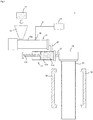
- the method of this embodiment can be performed using the foam blow molding machine 1 illustrated in Fig. 1 .
- the foam blow molding machine 1 comprises a hopper 12, an extruder 13, an injector 16, an accumulator 17, a head 18, and a split mold 19.
- the extruder 13 and the accumulator 17 are connected via a joint pipe 25.
- the accumulator 17 and the head 18 are connected via a joint pipe 27.
- the hopper 12 is used to inject the raw material resin 11 into a cylinder 13a of the extruder 13.
- the form of the raw material resin 11 is not particularly limited, but is typically pellets.
- the raw material resin 11 is injected into the cylinder 13a from the hopper 12 and then heated and melted in the cylinder 13a to become a molten resin. Further, by the rotation of the screw arranged in the cylinder 13a, the resin is conveyed toward the tip of the cylinder 13a.
- the screw is arranged in the cylinder 13a and conveys the molten resin while kneading the molten resin by the rotation thereof.
- a gear device is provided at the base end of the screw, and the screw is driven to rotate by the gear device.
- the cylinder 13a is provided with the injector 16 for injecting foaming gas into the cylinder 13a.
- the gas supply device 14 is connected to the injector 16 via a pipe 2.
- the foaming gas is injected into the cylinder 13a through the injector 16 while the pressure and flow rate of the foaming gas are adjusted in the gas supply device 14.
- the foaming gas is preferably injected into the cylinder 13a in the state of supercritical fluid.
- the gas supply device 14 is a device that supplies a foaming gas, and may be a device that supplies a gas from one or a plurality of cylinders as a foaming gas, or may be a device that supplies a gas obtained by extracting a desired component from air as a foaming gas.
- the foaming gas only needs to contain 0.1 to 1.0% of argon, and the remaining components include gases contained in air, such as nitrogen, oxygen and carbon dioxide.
- gases contained in air such as nitrogen, oxygen and carbon dioxide.
- the argon concentration in the foaming gas is specifically, for example, 0.1, 0.2, 0.3, 0.4, 0.5, 0.6, 0.7, 0.8, 0.9, 1.0%, and may be a value in the range between any two of these values exemplified here.
- the foaming gas preferably contains 98.0 to 99.9% (preferably 99.0 to 99.9%) of nitrogen.
- the nitrogen concentration in the foaming gas is specifically, for example, 98.0, 98.1, 98.2, 98.3, 98.4, 98.5, 98.6, 98.7, 98.8, 98.9, 99.0, 99.1, 99.2, 99.3, 99.4, 99.5, 99.6, 99.7, 99.8, 99.9%, and may be a value in the range between any two of these values exemplified here.
- the total concentration of nitrogen and argon in the foaming gas is, for example, 99 to 100%, specifically, for example, 99, 99.9, 99.99, 99.999, 99.9999, 100% and may be a value in the range between any two of these values exemplified here.
- the gas supply device 14 is preferably a nitrogen gas generation unit 15 which removes oxygen from air by using an adsorbent.
- Oxygen can be efficiently removed by such a nitrogen gas generation unit, but argon is hardly removed or is not removed at all, so that at least a part of argon contained in air remains in the obtained foaming gas. Therefore, the foaming gas containing 0.1 to 1.0% of argon can be obtained without adding argon separately.
- the adsorbent include microporous adsorbent such as activated carbon and zeolite.
- the nitrogen gas generation unit 15 comprises, for example, a compressor 15a, a tank 15b, a nitrogen gas generator 15c, a buffer tank 15d, a compressor 15e, and a buffer tank 15f.
- the compressor 15a is a facility for compressing air and is used to obtain a high-pressure air in a manufacturing factory.
- the tank 15b is a facility for storing the compressed air produced by the compressor 15a.
- the compressed air stored in the tank 15b is used to operate the nitrogen gas generator 15c.
- the nitrogen gas generator 15c is a facility that removes oxygen from the compressed air by using an adsorbent.
- the nitrogen gas is accumulated in the buffer tank 15d after its purity is increased.
- the compressor 15e is used to increase the pressure of the gas stored in the buffer tank 15d, and the buffer tank 15f is a facility provided to store the gas whose pressure is increased by the compressor 15e.
- branching the pipe 2 and connecting it to a nitrogen cylinder can achieve overall downsizing and can also ensure stability of the facility.
- the nitrogen gas generator 15c is a facility for removing oxygen from air, it is impossible to obtain a discharge pressure higher than the pressure of raw air for operation
- the pressure of the air compressed by the compressor 15a is about 0.7 MPa, and the discharge pressure of the nitrogen gas generator 15c is actually about 0.6 MPa.
- the facility increases the pressure to 1.0 MPa or more, it is regarded as a "high pressure gas production facility" to become difficult to sell.
- there is no demand for increasing the pressure of nitrogen to 1.0 MPa or more to consume there is almost no nitrogen gas generator applicable for increasing the pressure.
- the injector 16 is assumed to be supplied with a gas from the cylinder, and therefore requires a gas pressure of 1.5 MPa or more in order to confirm the residual quantity of the gas in the cylinder and to ensure the stability of increasing the pressure. Therefore, the compressor 15e for increasing the pressure is required immediately after the nitrogen gas generator 15c, that is, immediately before the injector 16. If the compressor 15e is too large, the buffer tank 15d becomes empty immediately and stable operation cannot be performed. If the compressor 15e is too small, it takes time to fill the buffer tank 15f. It is necessary to select compressor 15e having an appropriate size.
- the melt-kneaded resin obtained by melting and kneading the raw material resin and foaming gas are extruded from a resin extrusion port of the cylinder 13a and injected into the accumulator 17 through the joint pipe 25.
- the accumulator 17 comprises a cylinder 17a and a piston 17b slidable inside the cylinder 17a, and the melt-kneaded resin 11a can be stored in the cylinder 17a. Then, by moving the piston 17b after a predetermined amount of the melt-kneaded resin 11a is stored in the cylinder 17a, the melt-kneaded resin 11a is extruded through the joint pipe 27 from a die slit provided in the head 18 to form a foam parison 23.
- the shape of the foam parison 23 is not particularly limited and may be cylindrical or sheet.
- the foam parison 23 is guided between a pair of split molds 19.
- a foam molded body is obtained by molding the foam parison 23 using the split mold 19.
- the molding method using the split mold 19 is not particularly limited. The method may adopt blow molding in which the foam parison is molded by blowing air into cavity of the split molds 19, or vacuum molding in which the foam parison 23 is molded by decompressing the cavity of the split molds 19 from an inner surface of the cavity, and may adopt a combination thereof.
- the foam molded body was produced using the foam blow molding machine 1 shown in Fig. 1 , and foam moldability was evaluated.
- the inner diameter of the cylinder 13a of the extruder 13 was 50 mm, and L / D was 34.
- As the raw material resin a propylene homopolymer (manufactured by Borealis AG, product name "Daploy WB140”) and a long chain branched polypropylene (manufactured by Nippon Polypro Co., product name "EX6000K”) at a mass ratio of 30:70 were mixed.
- LDPE-based masterbatch manufactured by Dainichiseika Kogyo Co., Ltd., product name "Finecell Master P0217K" containing 20 wt% of sodium hydrogencarbonate-based foaming agent as a nucleating agent, and 1.0 part by weight of LLDPE-based masterbatch containing 40 wt% of carbon black as a colorant were added to 100 parts by weight of the resin.
- the temperature of each part was controlled so that the temperature of the foam parison 23 was 190 to 200°C.
- the number of rotations of the screw was 60 rmm, and the extrusion rate was 20 kg / hr.
- a gas generated by the nitrogen gas generation unit 15 shown in Fig. 2 was injected into the cylinder 13a via the injector 16.
- the nitrogen gas generator 15c adopts a PSA system that adsorbs oxygen using a microporous adsorbent.
- the total concentration of nitrogen and argon was 99.990%. Since the adsorbent removes little or no argon, the argon concentration in the foaming gas of Example 1 is 0.1 to 1.0%.
- the foam parison formed under the above conditions was used and placed between split molds for molding a cylindrical molded body. Then, after the split molds were clamped, blow molding was performed by blowing air at a pressure of 0.1 MPa into the foam parison to form a cylindrical foam molded body having the diameter of 50 mm, the height of 100 mm and the thickness of 5 mm.
- Comparative Example 1 a foam molded body was produced in the same manner as in Example 1, except that the gas from the nitrogen gas cylinder, which was filled with the nitrogen gas produced by the cryogenic separation method, was used as the foaming gas.
- the total concentration of nitrogen and argon in the foaming gas was 99.995%. Since the cryogenic separation method can remove argon, little or no argon remains in the foaming gas, and its concentration is less than 0.1%.
- FIG. 3A and Fig. 3B Cross-sectional photographs of the foam molded body of Example 1 and Comparative Example 1 are shown in Fig. 3A and Fig. 3B .
- the foam molded body of Example 1 has a significantly higher roundness of bubbles than the foam molded body of Comparative Example 1.
- each of the surface roughness (Ra) in the foam molded bodies of Example 1 and Comparative Example 1 was measured.
- the surface roughness (Ra) was 8.5 ⁇ m in Example 1 and 9.6 ⁇ m in Comparative Example 1. This result indicates that the foam molded body of Example 1 has a smoother surface than the foam molded body of Comparative Example 1.
- 1 foam blow molding machine
- 2 pipe
- 11 raw material resin
- 11a melt-kneaded resin
- 12 hopper
- 13 extruder
- 13a cylinder
- 14 gas supply device
- 15 nitrogen gas generation unit
- 15a compressor
- 15b tank
- 15c nitrogen gas generator
- 15d buffer tank
- 15e compressor
- 15f buffer tank
- 16 injector
- 17 accumulator
- 17a cylinder
- 17b piston
- 18 head
- 19 split mold
- 23 foam parison
- 25 joint pipe
- 27 joint pipe
Landscapes
- Engineering & Computer Science (AREA)
- Chemical & Material Sciences (AREA)
- Mechanical Engineering (AREA)
- Chemical Kinetics & Catalysis (AREA)
- Materials Engineering (AREA)
- Health & Medical Sciences (AREA)
- Manufacturing & Machinery (AREA)
- Medicinal Chemistry (AREA)
- Polymers & Plastics (AREA)
- Organic Chemistry (AREA)
- Blow-Moulding Or Thermoforming Of Plastics Or The Like (AREA)
- Molding Of Porous Articles (AREA)
- Manufacture Of Porous Articles, And Recovery And Treatment Of Waste Products (AREA)
Abstract
Description
- The present invention relates to a method for manufacturing a foam molded body.
- A tubular air conditioning duct for passing air is used, for example, in an air conditioner of an automobile and the like.
- A foam molded body using a foamed resin obtained by foaming thermoplastic resin with a foaming gas is known as an air conditioning duct. The foam molded body can achieve both of high heat insulation and light weight, and the demand therefor is increasing.
- A widely known method for manufacturing such a foam molded body is a blow molding method in which foamed resin in a molten state is clamped with a split mold, and air is blown into the interior to expand the resin (Patent Literature 1).
- Patent Literature 1:
JP-A-2012-030498 - By the way, the shape of bubbles in the foam molded body is preferably close to a perfect circle because the foam molded body has higher heat insulation as the shape of bubbles approaches a perfect circle. However, the shape of bubbles tends to become longer in the direction along the resin flow, and it is not easy to make the shape of bubbles close to a perfect circle.
- The present invention has been made in view of such circumstances and provides a method for manufacturing a foam molded body capable of making the shape of bubbles close to a perfect circle.
- According to the present invention, a method for manufacturing a foam molded body, comprising a step of forming a foam parison from a melt-kneaded resin obtained by melting and kneading a raw material resin and a foaming gas in a cylinder of an extruder and molding the foam parison to obtain the foam molded body, wherein the foaming gas contains 0.1 to 1.0% of argon, is provided.
- As a result of intensive studies by the present inventors, it has been found that the shape of bubbles approaches a perfect circle when the foaming gas contains 0.1 to 1.0% of argon, and the present invention has been derived therefrom.
- Hereinafter, various embodiments of the present invention are exemplified. The following embodiments can be combined with each other.
- Preferably, in the method described above, the foaming gas contains 98.0 to 99.9% of nitrogen.
- Preferably, in the method described above, the foaming gas is a gas obtained by using an adsorbent to remove oxygen from air.
- According to another viewpoint of the present invention, provided is a method for manufacturing a foam molded body, comprising a step of forming a foam parison from a melt-kneaded resin obtained by melting and kneading a raw material resin and a foaming gas in a cylinder of an extruder and molding the foam parison to obtain the foam molded body, wherein the foaming gas is a gas obtained by removing oxygen from air with an absorbent.
-
-
Fig. 1 is an example of a foamblow molding machine 1 that can be used in the method for manufacturing a foam molded body according to the embodiment of the present invention. -
Fig. 2 is a detailed configuration of a nitrogengas generation unit 15 inFig. 1 . -
Fig. 3A is a cross-sectional photograph of the foam molded body of Example 1, andFig. 3B is a cross-sectional photograph of the foam molded body of Comparative Example 1. - Hereinafter, embodiments of the present invention will be described. Various characteristics described in the following embodiments can be combined with each other. In addition, the invention is independently established for each characteristic.
- The method for manufacturing a foam molded body according to an embodiment of the present invention comprises a step of forming a foam parison from a melt-kneaded resin obtained by melting and kneading a raw material resin and a foaming gas in a cylinder of an extruder and molding the foam parison to obtain the foam molded body, wherein the foaming gas contains 0.1 to 1.0% of argon.
- The method of this embodiment can be performed using the foam
blow molding machine 1 illustrated inFig. 1 . The foamblow molding machine 1 comprises ahopper 12, anextruder 13, aninjector 16, anaccumulator 17, ahead 18, and asplit mold 19. Theextruder 13 and theaccumulator 17 are connected via ajoint pipe 25. Theaccumulator 17 and thehead 18 are connected via ajoint pipe 27. - Hereinafter, each component will be described in detail.
- The
hopper 12 is used to inject theraw material resin 11 into acylinder 13a of theextruder 13. The form of theraw material resin 11 is not particularly limited, but is typically pellets. Theraw material resin 11 is injected into thecylinder 13a from thehopper 12 and then heated and melted in thecylinder 13a to become a molten resin. Further, by the rotation of the screw arranged in thecylinder 13a, the resin is conveyed toward the tip of thecylinder 13a. The screw is arranged in thecylinder 13a and conveys the molten resin while kneading the molten resin by the rotation thereof. A gear device is provided at the base end of the screw, and the screw is driven to rotate by the gear device. - The
cylinder 13a is provided with theinjector 16 for injecting foaming gas into thecylinder 13a. Thegas supply device 14 is connected to theinjector 16 via apipe 2. - The foaming gas is injected into the
cylinder 13a through theinjector 16 while the pressure and flow rate of the foaming gas are adjusted in thegas supply device 14. The foaming gas is preferably injected into thecylinder 13a in the state of supercritical fluid. - The
gas supply device 14 is a device that supplies a foaming gas, and may be a device that supplies a gas from one or a plurality of cylinders as a foaming gas, or may be a device that supplies a gas obtained by extracting a desired component from air as a foaming gas. - The foaming gas only needs to contain 0.1 to 1.0% of argon, and the remaining components include gases contained in air, such as nitrogen, oxygen and carbon dioxide. By performing foam molding using such a foaming gas, the roundness of the bubbles in foam molding is increased.
- The argon concentration in the foaming gas is specifically, for example, 0.1, 0.2, 0.3, 0.4, 0.5, 0.6, 0.7, 0.8, 0.9, 1.0%, and may be a value in the range between any two of these values exemplified here. The foaming gas preferably contains 98.0 to 99.9% (preferably 99.0 to 99.9%) of nitrogen. The nitrogen concentration in the foaming gas is specifically, for example, 98.0, 98.1, 98.2, 98.3, 98.4, 98.5, 98.6, 98.7, 98.8, 98.9, 99.0, 99.1, 99.2, 99.3, 99.4, 99.5, 99.6, 99.7, 99.8, 99.9%, and may be a value in the range between any two of these values exemplified here. The total concentration of nitrogen and argon in the foaming gas is, for example, 99 to 100%, specifically, for example, 99, 99.9, 99.99, 99.999, 99.9999, 100% and may be a value in the range between any two of these values exemplified here.
- The
gas supply device 14 is preferably a nitrogengas generation unit 15 which removes oxygen from air by using an adsorbent. Oxygen can be efficiently removed by such a nitrogen gas generation unit, but argon is hardly removed or is not removed at all, so that at least a part of argon contained in air remains in the obtained foaming gas. Therefore, the foaming gas containing 0.1 to 1.0% of argon can be obtained without adding argon separately. Examples of the adsorbent include microporous adsorbent such as activated carbon and zeolite. - As shown in
Fig. 2 , the nitrogengas generation unit 15 comprises, for example, a compressor 15a, a tank 15b, anitrogen gas generator 15c, a buffer tank 15d, acompressor 15e, and abuffer tank 15f. - The compressor 15a is a facility for compressing air and is used to obtain a high-pressure air in a manufacturing factory. The tank 15b is a facility for storing the compressed air produced by the compressor 15a. When the factory in which the nitrogen
gas generation unit 15 is installed is already equipped with the facility corresponding to the compressor 15a and the tank 15b, it is not necessary to separately prepare the compressor 15a and the tank 15b. - The compressed air stored in the tank 15b is used to operate the
nitrogen gas generator 15c. Thenitrogen gas generator 15c is a facility that removes oxygen from the compressed air by using an adsorbent. The nitrogen gas is accumulated in the buffer tank 15d after its purity is increased. Thecompressor 15e is used to increase the pressure of the gas stored in the buffer tank 15d, and thebuffer tank 15f is a facility provided to store the gas whose pressure is increased by thecompressor 15e. - In addition, since a large amount of the foaming gas is consumed at the start of production (the total consumption is small), branching the
pipe 2 and connecting it to a nitrogen cylinder can achieve overall downsizing and can also ensure stability of the facility. - Since the
nitrogen gas generator 15c is a facility for removing oxygen from air, it is impossible to obtain a discharge pressure higher than the pressure of raw air for operation The pressure of the air compressed by the compressor 15a is about 0.7 MPa, and the discharge pressure of thenitrogen gas generator 15c is actually about 0.6 MPa. In Japan, when the facility increases the pressure to 1.0 MPa or more, it is regarded as a "high pressure gas production facility" to become difficult to sell. Further, since there is no demand for increasing the pressure of nitrogen to 1.0 MPa or more to consume, there is almost no nitrogen gas generator applicable for increasing the pressure. - On the other hand, the
injector 16 is assumed to be supplied with a gas from the cylinder, and therefore requires a gas pressure of 1.5 MPa or more in order to confirm the residual quantity of the gas in the cylinder and to ensure the stability of increasing the pressure. Therefore, thecompressor 15e for increasing the pressure is required immediately after thenitrogen gas generator 15c, that is, immediately before theinjector 16. If thecompressor 15e is too large, the buffer tank 15d becomes empty immediately and stable operation cannot be performed. If thecompressor 15e is too small, it takes time to fill thebuffer tank 15f. It is necessary to selectcompressor 15e having an appropriate size. - <
Accumulator 17,Head 18> - The melt-kneaded resin obtained by melting and kneading the raw material resin and foaming gas are extruded from a resin extrusion port of the
cylinder 13a and injected into theaccumulator 17 through thejoint pipe 25. Theaccumulator 17 comprises acylinder 17a and apiston 17b slidable inside thecylinder 17a, and the melt-kneadedresin 11a can be stored in thecylinder 17a. Then, by moving thepiston 17b after a predetermined amount of the melt-kneadedresin 11a is stored in thecylinder 17a, the melt-kneadedresin 11a is extruded through thejoint pipe 27 from a die slit provided in thehead 18 to form afoam parison 23. The shape of thefoam parison 23 is not particularly limited and may be cylindrical or sheet. - The
foam parison 23 is guided between a pair ofsplit molds 19. A foam molded body is obtained by molding thefoam parison 23 using thesplit mold 19. The molding method using thesplit mold 19 is not particularly limited. The method may adopt blow molding in which the foam parison is molded by blowing air into cavity of thesplit molds 19, or vacuum molding in which thefoam parison 23 is molded by decompressing the cavity of thesplit molds 19 from an inner surface of the cavity, and may adopt a combination thereof. - The foam molded body was produced using the foam
blow molding machine 1 shown inFig. 1 , and foam moldability was evaluated. The inner diameter of thecylinder 13a of theextruder 13 was 50 mm, and L / D was 34. As the raw material resin, a propylene homopolymer (manufactured by Borealis AG, product name "Daploy WB140") and a long chain branched polypropylene (manufactured by Nippon Polypro Co., product name "EX6000K") at a mass ratio of 30:70 were mixed. 1.0 part by weight of LDPE-based masterbatch (manufactured by Dainichiseika Kogyo Co., Ltd., product name "Finecell Master P0217K") containing 20 wt% of sodium hydrogencarbonate-based foaming agent as a nucleating agent, and 1.0 part by weight of LLDPE-based masterbatch containing 40 wt% of carbon black as a colorant were added to 100 parts by weight of the resin. The temperature of each part was controlled so that the temperature of thefoam parison 23 was 190 to 200°C. The number of rotations of the screw was 60 rmm, and the extrusion rate was 20 kg / hr. - As the foaming gas, a gas generated by the nitrogen
gas generation unit 15 shown inFig. 2 was injected into thecylinder 13a via theinjector 16. Thenitrogen gas generator 15c adopts a PSA system that adsorbs oxygen using a microporous adsorbent. The total concentration of nitrogen and argon was 99.990%. Since the adsorbent removes little or no argon, the argon concentration in the foaming gas of Example 1 is 0.1 to 1.0%. - The foam parison formed under the above conditions was used and placed between split molds for molding a cylindrical molded body. Then, after the split molds were clamped, blow molding was performed by blowing air at a pressure of 0.1 MPa into the foam parison to form a cylindrical foam molded body having the diameter of 50 mm, the height of 100 mm and the thickness of 5 mm.
- In Comparative Example 1, a foam molded body was produced in the same manner as in Example 1, except that the gas from the nitrogen gas cylinder, which was filled with the nitrogen gas produced by the cryogenic separation method, was used as the foaming gas.
- The total concentration of nitrogen and argon in the foaming gas was 99.995%. Since the cryogenic separation method can remove argon, little or no argon remains in the foaming gas, and its concentration is less than 0.1%.
- Cross-sectional photographs of the foam molded body of Example 1 and Comparative Example 1 are shown in
Fig. 3A and Fig. 3B . As shown inFig. 3A and Fig. 3B , the foam molded body of Example 1 has a significantly higher roundness of bubbles than the foam molded body of Comparative Example 1. - Furthermore, each of the surface roughness (Ra) in the foam molded bodies of Example 1 and Comparative Example 1 was measured. As a result, the surface roughness (Ra) was 8.5 µm in Example 1 and 9.6 µm in Comparative Example 1. This result indicates that the foam molded body of Example 1 has a smoother surface than the foam molded body of Comparative Example 1.
- 1: foam blow molding machine, 2: pipe, 11: raw material resin, 11a: melt-kneaded resin, 12: hopper, 13: extruder, 13a: cylinder, 14: gas supply device, 15: nitrogen gas generation unit, 15a: compressor, 15b: tank, 15c: nitrogen gas generator, 15d: buffer tank, 15e: compressor, 15f: buffer tank, 16: injector, 17: accumulator, 17a: cylinder, 17b: piston, 18: head, 19: split mold, 23: foam parison, 25: joint pipe, 27: joint pipe
Claims (4)
- A method for manufacturing a foam molded body, comprising a step of forming a foam parison from a melt-kneaded resin obtained by melting and kneading a raw material resin and a foaming gas in a cylinder of an extruder and molding the foam parison to obtain the foam molded body, wherein the foaming gas contains 0.1 to 1.0% of argon.
- The method of Claim 1, wherein the foaming gas contains 98.0 to 99.9% of nitrogen.
- The method of Claim 1 or 2, wherein the foaming gas is a gas obtained by removing oxygen from air with an absorbent.
- A method for manufacturing a foam molded body, comprising a step of forming a foam parison from a melt-kneaded resin obtained by melting and kneading a raw material resin and a foaming gas in a cylinder of an extruder and molding the foam parison to obtain the foam molded body, wherein the foaming gas is a gas obtained by removing oxygen from air with an absorbent.
Applications Claiming Priority (2)
| Application Number | Priority Date | Filing Date | Title |
|---|---|---|---|
| JP2018065785A JP7132487B2 (en) | 2018-03-29 | 2018-03-29 | Method for producing foam molded article |
| PCT/JP2019/012042 WO2019188764A1 (en) | 2018-03-29 | 2019-03-22 | Method for manufacturing foam molded body |
Publications (3)
| Publication Number | Publication Date |
|---|---|
| EP3778175A1 true EP3778175A1 (en) | 2021-02-17 |
| EP3778175A4 EP3778175A4 (en) | 2021-05-19 |
| EP3778175B1 EP3778175B1 (en) | 2024-08-21 |
Family
ID=68061724
Family Applications (1)
| Application Number | Title | Priority Date | Filing Date |
|---|---|---|---|
| EP19778168.5A Active EP3778175B1 (en) | 2018-03-29 | 2019-03-22 | Method for manufacturing foam molded body |
Country Status (6)
| Country | Link |
|---|---|
| US (1) | US11679537B2 (en) |
| EP (1) | EP3778175B1 (en) |
| JP (1) | JP7132487B2 (en) |
| KR (1) | KR102779032B1 (en) |
| CN (1) | CN111556803A (en) |
| WO (1) | WO2019188764A1 (en) |
Family Cites Families (17)
| Publication number | Priority date | Publication date | Assignee | Title |
|---|---|---|---|---|
| US6602063B1 (en) | 2000-07-21 | 2003-08-05 | Trexel, Inc. | Discontinuous blowing agent delivery system and method |
| US20040166042A1 (en) * | 2002-11-26 | 2004-08-26 | Fukuhara Co., Ltd. | Method and apparatus for producing nitrogen gas |
| JP2005343776A (en) * | 2004-05-31 | 2005-12-15 | Fukuhara Co Ltd | Method and apparatus for producing gaseous nitrogen |
| US7588612B2 (en) * | 2005-07-19 | 2009-09-15 | Bank Of America, N.A. | Mobile nitrogen generation device |
| US20100239845A1 (en) * | 2006-09-29 | 2010-09-23 | Tomofumi Maekawa | Thermoplastic resin composition foamed sheet and method for producing the same |
| CN101959942B (en) * | 2007-12-28 | 2013-05-08 | 陶氏环球技术有限责任公司 | PE-based crosslinked elastomeric foam with high filler loadings for making shockpads and articles used in footwear and flooring applications |
| JP5602468B2 (en) * | 2010-03-24 | 2014-10-08 | 株式会社ジェイエスピー | Method for producing polypropylene resin foam blow molded article |
| JP5589651B2 (en) | 2010-07-30 | 2014-09-17 | キョーラク株式会社 | Method for producing foam molded body and foam molded body |
| CN102321309B (en) * | 2011-06-09 | 2012-10-31 | 四川大学 | Polymer foam composite material with gradient structure and its preparation method |
| WO2013114996A1 (en) * | 2012-01-30 | 2013-08-08 | キョーラク株式会社 | Method for manufacturing foam-molded article, and foam-molded article |
| US20150267019A1 (en) * | 2012-10-22 | 2015-09-24 | Toyo Seikan Group Holdings, Ltd. | Foamed stretch- formed polyolefin resin body |
| JP6331390B2 (en) * | 2013-12-27 | 2018-05-30 | キョーラク株式会社 | Foam molding |
| BR112016018907B1 (en) * | 2014-02-28 | 2021-07-06 | Mitsui Chemicals, Inc | method for producing a crosslinked product, laminated molded article, ethylene copolymer (a) and ethylene copolymer composition |
| JP5993108B1 (en) * | 2015-03-18 | 2016-09-14 | バンドー化学株式会社 | Foaming resin composition and foamed molded article |
| CN104877162B (en) * | 2015-04-27 | 2017-11-17 | 中国科学院长春应用化学研究所 | The composite foamed particle of in-situ micro-fibril polypropylene-based resin and its application |
| JP6139038B1 (en) * | 2015-07-08 | 2017-05-31 | 日立マクセル株式会社 | Method for producing foam molded article |
| KR102191502B1 (en) * | 2015-09-28 | 2020-12-15 | 교라꾸 가부시끼가이샤 | Manufacturing device of foam molded article and its manufacturing method |
-
2018
- 2018-03-29 JP JP2018065785A patent/JP7132487B2/en active Active
-
2019
- 2019-03-22 US US16/976,817 patent/US11679537B2/en active Active
- 2019-03-22 KR KR1020207018715A patent/KR102779032B1/en active Active
- 2019-03-22 CN CN201980007481.XA patent/CN111556803A/en active Pending
- 2019-03-22 WO PCT/JP2019/012042 patent/WO2019188764A1/en not_active Ceased
- 2019-03-22 EP EP19778168.5A patent/EP3778175B1/en active Active
Also Published As
| Publication number | Publication date |
|---|---|
| KR20200132839A (en) | 2020-11-25 |
| KR102779032B1 (en) | 2025-03-07 |
| US11679537B2 (en) | 2023-06-20 |
| EP3778175B1 (en) | 2024-08-21 |
| JP2019171816A (en) | 2019-10-10 |
| EP3778175A4 (en) | 2021-05-19 |
| WO2019188764A1 (en) | 2019-10-03 |
| CN111556803A (en) | 2020-08-18 |
| JP7132487B2 (en) | 2022-09-07 |
| US20200398463A1 (en) | 2020-12-24 |
Similar Documents
| Publication | Publication Date | Title |
|---|---|---|
| US7858002B2 (en) | Method for injection expansion molding of thermoplastic resin | |
| EP4108406B1 (en) | Process and device for producing molded foam | |
| CN107849282B (en) | Resin for foam molding and method for producing foam molded product | |
| EP1072389A4 (en) | Blow-molded foam and process for producing the same | |
| US3150214A (en) | Method of extruding a foamed plastic composition | |
| MX2013006110A (en) | Method and device for producing pipe member. | |
| JP6454146B2 (en) | Hollow molding injection molding method | |
| CN110667027B (en) | Method and apparatus for producing foamed molded body | |
| KR102557789B1 (en) | Resin for foam molding, foam molded article, manufacturing method of foam molded article | |
| EP3778175B1 (en) | Method for manufacturing foam molded body | |
| JP7817527B2 (en) | Method for producing foamed molded article | |
| JP2001301006A (en) | Method and apparatus for manufacturing thermoplastic resin molded article | |
| US20020122838A1 (en) | Blow molding method and system | |
| JP6920604B2 (en) | Foam molded product and its manufacturing method | |
| JP6845426B2 (en) | Foam molding resin, foam molding and its manufacturing method | |
| US9724857B2 (en) | Compression molded polymeric foam articles and methods | |
| JP3877394B2 (en) | Method for producing ultra-high molecular weight polyethylene foam | |
| JP6593065B2 (en) | Method for producing foam molded article | |
| JP2001269982A (en) | Manufacturing equipment for resin moldings | |
| JP6770228B2 (en) | Manufacturing method of foam molded product | |
| JPH10128826A (en) | Method for producing biodegradable resin foam sheet | |
| JP2018034352A (en) | Method for producing foam molded article | |
| JP2019147886A (en) | Resin for extrusion molding, and manufacturing method of molding | |
| CN110625960A (en) | Special physical foaming extrusion equipment for polypropylene composite material | |
| JP2001002809A (en) | Crystalline resin sheet and method for producing the same |
Legal Events
| Date | Code | Title | Description |
|---|---|---|---|
| STAA | Information on the status of an ep patent application or granted ep patent |
Free format text: STATUS: THE INTERNATIONAL PUBLICATION HAS BEEN MADE |
|
| PUAI | Public reference made under article 153(3) epc to a published international application that has entered the european phase |
Free format text: ORIGINAL CODE: 0009012 |
|
| STAA | Information on the status of an ep patent application or granted ep patent |
Free format text: STATUS: REQUEST FOR EXAMINATION WAS MADE |
|
| 17P | Request for examination filed |
Effective date: 20200928 |
|
| AK | Designated contracting states |
Kind code of ref document: A1 Designated state(s): AL AT BE BG CH CY CZ DE DK EE ES FI FR GB GR HR HU IE IS IT LI LT LU LV MC MK MT NL NO PL PT RO RS SE SI SK SM TR |
|
| AX | Request for extension of the european patent |
Extension state: BA ME |
|
| A4 | Supplementary search report drawn up and despatched |
Effective date: 20210415 |
|
| RIC1 | Information provided on ipc code assigned before grant |
Ipc: B29C 44/00 20060101AFI20210409BHEP Ipc: B29C 44/50 20060101ALI20210409BHEP Ipc: B29C 44/56 20060101ALI20210409BHEP Ipc: B29C 49/04 20060101ALI20210409BHEP Ipc: C08J 9/12 20060101ALI20210409BHEP Ipc: B29K 101/12 20060101ALI20210409BHEP |
|
| DAV | Request for validation of the european patent (deleted) | ||
| DAX | Request for extension of the european patent (deleted) | ||
| STAA | Information on the status of an ep patent application or granted ep patent |
Free format text: STATUS: EXAMINATION IS IN PROGRESS |
|
| 17Q | First examination report despatched |
Effective date: 20211125 |
|
| GRAP | Despatch of communication of intention to grant a patent |
Free format text: ORIGINAL CODE: EPIDOSNIGR1 |
|
| STAA | Information on the status of an ep patent application or granted ep patent |
Free format text: STATUS: GRANT OF PATENT IS INTENDED |
|
| INTG | Intention to grant announced |
Effective date: 20240322 |
|
| GRAS | Grant fee paid |
Free format text: ORIGINAL CODE: EPIDOSNIGR3 |
|
| GRAA | (expected) grant |
Free format text: ORIGINAL CODE: 0009210 |
|
| STAA | Information on the status of an ep patent application or granted ep patent |
Free format text: STATUS: THE PATENT HAS BEEN GRANTED |
|
| AK | Designated contracting states |
Kind code of ref document: B1 Designated state(s): AL AT BE BG CH CY CZ DE DK EE ES FI FR GB GR HR HU IE IS IT LI LT LU LV MC MK MT NL NO PL PT RO RS SE SI SK SM TR |
|
| REG | Reference to a national code |
Ref country code: GB Ref legal event code: FG4D |
|
| REG | Reference to a national code |
Ref country code: CH Ref legal event code: EP |
|
| REG | Reference to a national code |
Ref country code: IE Ref legal event code: FG4D |
|
| REG | Reference to a national code |
Ref country code: DE Ref legal event code: R096 Ref document number: 602019057454 Country of ref document: DE |
|
| REG | Reference to a national code |
Ref country code: LT Ref legal event code: MG9D |
|
| REG | Reference to a national code |
Ref country code: NL Ref legal event code: MP Effective date: 20240821 |
|
| PG25 | Lapsed in a contracting state [announced via postgrant information from national office to epo] |
Ref country code: NO Free format text: LAPSE BECAUSE OF FAILURE TO SUBMIT A TRANSLATION OF THE DESCRIPTION OR TO PAY THE FEE WITHIN THE PRESCRIBED TIME-LIMIT Effective date: 20241121 |
|
| REG | Reference to a national code |
Ref country code: AT Ref legal event code: MK05 Ref document number: 1715121 Country of ref document: AT Kind code of ref document: T Effective date: 20240821 |
|
| PG25 | Lapsed in a contracting state [announced via postgrant information from national office to epo] |
Ref country code: NL Free format text: LAPSE BECAUSE OF FAILURE TO SUBMIT A TRANSLATION OF THE DESCRIPTION OR TO PAY THE FEE WITHIN THE PRESCRIBED TIME-LIMIT Effective date: 20240821 Ref country code: FI Free format text: LAPSE BECAUSE OF FAILURE TO SUBMIT A TRANSLATION OF THE DESCRIPTION OR TO PAY THE FEE WITHIN THE PRESCRIBED TIME-LIMIT Effective date: 20240821 Ref country code: PL Free format text: LAPSE BECAUSE OF FAILURE TO SUBMIT A TRANSLATION OF THE DESCRIPTION OR TO PAY THE FEE WITHIN THE PRESCRIBED TIME-LIMIT Effective date: 20240821 Ref country code: GR Free format text: LAPSE BECAUSE OF FAILURE TO SUBMIT A TRANSLATION OF THE DESCRIPTION OR TO PAY THE FEE WITHIN THE PRESCRIBED TIME-LIMIT Effective date: 20241122 Ref country code: PT Free format text: LAPSE BECAUSE OF FAILURE TO SUBMIT A TRANSLATION OF THE DESCRIPTION OR TO PAY THE FEE WITHIN THE PRESCRIBED TIME-LIMIT Effective date: 20241223 |
|
| PG25 | Lapsed in a contracting state [announced via postgrant information from national office to epo] |
Ref country code: BG Free format text: LAPSE BECAUSE OF FAILURE TO SUBMIT A TRANSLATION OF THE DESCRIPTION OR TO PAY THE FEE WITHIN THE PRESCRIBED TIME-LIMIT Effective date: 20240821 |
|
| PG25 | Lapsed in a contracting state [announced via postgrant information from national office to epo] |
Ref country code: LV Free format text: LAPSE BECAUSE OF FAILURE TO SUBMIT A TRANSLATION OF THE DESCRIPTION OR TO PAY THE FEE WITHIN THE PRESCRIBED TIME-LIMIT Effective date: 20240821 |
|
| PG25 | Lapsed in a contracting state [announced via postgrant information from national office to epo] |
Ref country code: AT Free format text: LAPSE BECAUSE OF FAILURE TO SUBMIT A TRANSLATION OF THE DESCRIPTION OR TO PAY THE FEE WITHIN THE PRESCRIBED TIME-LIMIT Effective date: 20240821 Ref country code: IS Free format text: LAPSE BECAUSE OF FAILURE TO SUBMIT A TRANSLATION OF THE DESCRIPTION OR TO PAY THE FEE WITHIN THE PRESCRIBED TIME-LIMIT Effective date: 20241221 |
|
| PG25 | Lapsed in a contracting state [announced via postgrant information from national office to epo] |
Ref country code: HR Free format text: LAPSE BECAUSE OF FAILURE TO SUBMIT A TRANSLATION OF THE DESCRIPTION OR TO PAY THE FEE WITHIN THE PRESCRIBED TIME-LIMIT Effective date: 20240821 |
|
| PG25 | Lapsed in a contracting state [announced via postgrant information from national office to epo] |
Ref country code: ES Free format text: LAPSE BECAUSE OF FAILURE TO SUBMIT A TRANSLATION OF THE DESCRIPTION OR TO PAY THE FEE WITHIN THE PRESCRIBED TIME-LIMIT Effective date: 20240821 Ref country code: RS Free format text: LAPSE BECAUSE OF FAILURE TO SUBMIT A TRANSLATION OF THE DESCRIPTION OR TO PAY THE FEE WITHIN THE PRESCRIBED TIME-LIMIT Effective date: 20241121 |
|
| PG25 | Lapsed in a contracting state [announced via postgrant information from national office to epo] |
Ref country code: RS Free format text: LAPSE BECAUSE OF FAILURE TO SUBMIT A TRANSLATION OF THE DESCRIPTION OR TO PAY THE FEE WITHIN THE PRESCRIBED TIME-LIMIT Effective date: 20241121 Ref country code: PT Free format text: LAPSE BECAUSE OF FAILURE TO SUBMIT A TRANSLATION OF THE DESCRIPTION OR TO PAY THE FEE WITHIN THE PRESCRIBED TIME-LIMIT Effective date: 20241223 Ref country code: PL Free format text: LAPSE BECAUSE OF FAILURE TO SUBMIT A TRANSLATION OF THE DESCRIPTION OR TO PAY THE FEE WITHIN THE PRESCRIBED TIME-LIMIT Effective date: 20240821 Ref country code: NO Free format text: LAPSE BECAUSE OF FAILURE TO SUBMIT A TRANSLATION OF THE DESCRIPTION OR TO PAY THE FEE WITHIN THE PRESCRIBED TIME-LIMIT Effective date: 20241121 Ref country code: NL Free format text: LAPSE BECAUSE OF FAILURE TO SUBMIT A TRANSLATION OF THE DESCRIPTION OR TO PAY THE FEE WITHIN THE PRESCRIBED TIME-LIMIT Effective date: 20240821 Ref country code: LV Free format text: LAPSE BECAUSE OF FAILURE TO SUBMIT A TRANSLATION OF THE DESCRIPTION OR TO PAY THE FEE WITHIN THE PRESCRIBED TIME-LIMIT Effective date: 20240821 Ref country code: IS Free format text: LAPSE BECAUSE OF FAILURE TO SUBMIT A TRANSLATION OF THE DESCRIPTION OR TO PAY THE FEE WITHIN THE PRESCRIBED TIME-LIMIT Effective date: 20241221 Ref country code: HR Free format text: LAPSE BECAUSE OF FAILURE TO SUBMIT A TRANSLATION OF THE DESCRIPTION OR TO PAY THE FEE WITHIN THE PRESCRIBED TIME-LIMIT Effective date: 20240821 Ref country code: GR Free format text: LAPSE BECAUSE OF FAILURE TO SUBMIT A TRANSLATION OF THE DESCRIPTION OR TO PAY THE FEE WITHIN THE PRESCRIBED TIME-LIMIT Effective date: 20241122 Ref country code: FI Free format text: LAPSE BECAUSE OF FAILURE TO SUBMIT A TRANSLATION OF THE DESCRIPTION OR TO PAY THE FEE WITHIN THE PRESCRIBED TIME-LIMIT Effective date: 20240821 Ref country code: ES Free format text: LAPSE BECAUSE OF FAILURE TO SUBMIT A TRANSLATION OF THE DESCRIPTION OR TO PAY THE FEE WITHIN THE PRESCRIBED TIME-LIMIT Effective date: 20240821 Ref country code: BG Free format text: LAPSE BECAUSE OF FAILURE TO SUBMIT A TRANSLATION OF THE DESCRIPTION OR TO PAY THE FEE WITHIN THE PRESCRIBED TIME-LIMIT Effective date: 20240821 Ref country code: AT Free format text: LAPSE BECAUSE OF FAILURE TO SUBMIT A TRANSLATION OF THE DESCRIPTION OR TO PAY THE FEE WITHIN THE PRESCRIBED TIME-LIMIT Effective date: 20240821 |
|
| PG25 | Lapsed in a contracting state [announced via postgrant information from national office to epo] |
Ref country code: DK Free format text: LAPSE BECAUSE OF FAILURE TO SUBMIT A TRANSLATION OF THE DESCRIPTION OR TO PAY THE FEE WITHIN THE PRESCRIBED TIME-LIMIT Effective date: 20240821 Ref country code: RO Free format text: LAPSE BECAUSE OF FAILURE TO SUBMIT A TRANSLATION OF THE DESCRIPTION OR TO PAY THE FEE WITHIN THE PRESCRIBED TIME-LIMIT Effective date: 20240821 Ref country code: SM Free format text: LAPSE BECAUSE OF FAILURE TO SUBMIT A TRANSLATION OF THE DESCRIPTION OR TO PAY THE FEE WITHIN THE PRESCRIBED TIME-LIMIT Effective date: 20240821 |
|
| PG25 | Lapsed in a contracting state [announced via postgrant information from national office to epo] |
Ref country code: EE Free format text: LAPSE BECAUSE OF FAILURE TO SUBMIT A TRANSLATION OF THE DESCRIPTION OR TO PAY THE FEE WITHIN THE PRESCRIBED TIME-LIMIT Effective date: 20240821 |
|
| PG25 | Lapsed in a contracting state [announced via postgrant information from national office to epo] |
Ref country code: CZ Free format text: LAPSE BECAUSE OF FAILURE TO SUBMIT A TRANSLATION OF THE DESCRIPTION OR TO PAY THE FEE WITHIN THE PRESCRIBED TIME-LIMIT Effective date: 20240821 |
|
| PG25 | Lapsed in a contracting state [announced via postgrant information from national office to epo] |
Ref country code: IT Free format text: LAPSE BECAUSE OF FAILURE TO SUBMIT A TRANSLATION OF THE DESCRIPTION OR TO PAY THE FEE WITHIN THE PRESCRIBED TIME-LIMIT Effective date: 20240821 Ref country code: SK Free format text: LAPSE BECAUSE OF FAILURE TO SUBMIT A TRANSLATION OF THE DESCRIPTION OR TO PAY THE FEE WITHIN THE PRESCRIBED TIME-LIMIT Effective date: 20240821 |
|
| REG | Reference to a national code |
Ref country code: DE Ref legal event code: R097 Ref document number: 602019057454 Country of ref document: DE |
|
| PLBE | No opposition filed within time limit |
Free format text: ORIGINAL CODE: 0009261 |
|
| STAA | Information on the status of an ep patent application or granted ep patent |
Free format text: STATUS: NO OPPOSITION FILED WITHIN TIME LIMIT |
|
| 26N | No opposition filed |
Effective date: 20250522 |
|
| PG25 | Lapsed in a contracting state [announced via postgrant information from national office to epo] |
Ref country code: SE Free format text: LAPSE BECAUSE OF FAILURE TO SUBMIT A TRANSLATION OF THE DESCRIPTION OR TO PAY THE FEE WITHIN THE PRESCRIBED TIME-LIMIT Effective date: 20240821 |
|
| PG25 | Lapsed in a contracting state [announced via postgrant information from national office to epo] |
Ref country code: MC Free format text: LAPSE BECAUSE OF FAILURE TO SUBMIT A TRANSLATION OF THE DESCRIPTION OR TO PAY THE FEE WITHIN THE PRESCRIBED TIME-LIMIT Effective date: 20240821 |
|
| REG | Reference to a national code |
Ref country code: CH Ref legal event code: H13 Free format text: ST27 STATUS EVENT CODE: U-0-0-H10-H13 (AS PROVIDED BY THE NATIONAL OFFICE) Effective date: 20251023 |
|
| PG25 | Lapsed in a contracting state [announced via postgrant information from national office to epo] |
Ref country code: LU Free format text: LAPSE BECAUSE OF NON-PAYMENT OF DUE FEES Effective date: 20250322 |
|
| REG | Reference to a national code |
Ref country code: BE Ref legal event code: MM Effective date: 20250331 |
|
| PG25 | Lapsed in a contracting state [announced via postgrant information from national office to epo] |
Ref country code: BE Free format text: LAPSE BECAUSE OF NON-PAYMENT OF DUE FEES Effective date: 20250331 |
|
| PG25 | Lapsed in a contracting state [announced via postgrant information from national office to epo] |
Ref country code: CH Free format text: LAPSE BECAUSE OF NON-PAYMENT OF DUE FEES Effective date: 20250331 |
|
| PG25 | Lapsed in a contracting state [announced via postgrant information from national office to epo] |
Ref country code: IE Free format text: LAPSE BECAUSE OF NON-PAYMENT OF DUE FEES Effective date: 20250322 |
|
| PGFP | Annual fee paid to national office [announced via postgrant information from national office to epo] |
Ref country code: GB Payment date: 20260324 Year of fee payment: 8 |
|
| PGFP | Annual fee paid to national office [announced via postgrant information from national office to epo] |
Ref country code: DE Payment date: 20260319 Year of fee payment: 8 |
|
| PGFP | Annual fee paid to national office [announced via postgrant information from national office to epo] |
Ref country code: FR Payment date: 20260323 Year of fee payment: 8 |