EP3778119A1 - Dresser - Google Patents
Dresser Download PDFInfo
- Publication number
- EP3778119A1 EP3778119A1 EP19785879.8A EP19785879A EP3778119A1 EP 3778119 A1 EP3778119 A1 EP 3778119A1 EP 19785879 A EP19785879 A EP 19785879A EP 3778119 A1 EP3778119 A1 EP 3778119A1
- Authority
- EP
- European Patent Office
- Prior art keywords
- cutting edge
- edge component
- component
- dresser
- insertion direction
- Prior art date
- Legal status (The legal status is an assumption and is not a legal conclusion. Google has not performed a legal analysis and makes no representation as to the accuracy of the status listed.)
- Granted
Links
Images


Classifications
-
- B—PERFORMING OPERATIONS; TRANSPORTING
- B24—GRINDING; POLISHING
- B24B—MACHINES, DEVICES, OR PROCESSES FOR GRINDING OR POLISHING; DRESSING OR CONDITIONING OF ABRADING SURFACES; FEEDING OF GRINDING, POLISHING, OR LAPPING AGENTS
- B24B53/00—Devices or means for dressing or conditioning abrasive surfaces
- B24B53/12—Dressing tools; Holders therefor
- B24B53/14—Dressing tools equipped with rotary rollers or cutters; Holders therefor
-
- B—PERFORMING OPERATIONS; TRANSPORTING
- B24—GRINDING; POLISHING
- B24B—MACHINES, DEVICES, OR PROCESSES FOR GRINDING OR POLISHING; DRESSING OR CONDITIONING OF ABRADING SURFACES; FEEDING OF GRINDING, POLISHING, OR LAPPING AGENTS
- B24B53/00—Devices or means for dressing or conditioning abrasive surfaces
- B24B53/017—Devices or means for dressing, cleaning or otherwise conditioning lapping tools
-
- B—PERFORMING OPERATIONS; TRANSPORTING
- B24—GRINDING; POLISHING
- B24B—MACHINES, DEVICES, OR PROCESSES FOR GRINDING OR POLISHING; DRESSING OR CONDITIONING OF ABRADING SURFACES; FEEDING OF GRINDING, POLISHING, OR LAPPING AGENTS
- B24B53/00—Devices or means for dressing or conditioning abrasive surfaces
- B24B53/04—Devices or means for dressing or conditioning abrasive surfaces of cylindrical or conical surfaces on abrasive tools or wheels
- B24B53/047—Devices or means for dressing or conditioning abrasive surfaces of cylindrical or conical surfaces on abrasive tools or wheels equipped with one or more diamonds
-
- B—PERFORMING OPERATIONS; TRANSPORTING
- B24—GRINDING; POLISHING
- B24B—MACHINES, DEVICES, OR PROCESSES FOR GRINDING OR POLISHING; DRESSING OR CONDITIONING OF ABRADING SURFACES; FEEDING OF GRINDING, POLISHING, OR LAPPING AGENTS
- B24B53/00—Devices or means for dressing or conditioning abrasive surfaces
- B24B53/12—Dressing tools; Holders therefor
-
- B—PERFORMING OPERATIONS; TRANSPORTING
- B24—GRINDING; POLISHING
- B24D—TOOLS FOR GRINDING, BUFFING OR SHARPENING
- B24D3/00—Physical features of abrasive bodies, or sheets, e.g. abrasive surfaces of special nature; Abrasive bodies or sheets characterised by their constituents
- B24D3/007—Physical features of abrasive bodies, or sheets, e.g. abrasive surfaces of special nature; Abrasive bodies or sheets characterised by their constituents the constituent being used as bonding agent between different parts of an abrasive tool
-
- B—PERFORMING OPERATIONS; TRANSPORTING
- B24—GRINDING; POLISHING
- B24D—TOOLS FOR GRINDING, BUFFING OR SHARPENING
- B24D5/00—Bonded abrasive wheels, or wheels with inserted abrasive blocks, designed for acting only by their periphery; Bushings or mountings therefor
- B24D5/06—Bonded abrasive wheels, or wheels with inserted abrasive blocks, designed for acting only by their periphery; Bushings or mountings therefor with inserted abrasive blocks, e.g. segmental
Definitions
- the present disclosure relates to a dresser.
- the present application claims a priority based on Japanese Patent Application No. 2018-076822 filed on April 12, 2018 , the entire content of which is incorporated herein by reference.
- Patent Literature 1 discloses a diamond dresser, wherein a single-crystal columnar diamond is embedded in a dressing surface of a substrate.
- a front end portion (portion exposed from the substrate) of the single-crystal columnar diamond serving as a cutting edge is gradually worn due to use thereof.
- the life thereof is expired in the following manner: a diamond portion ceases to exist; or the diamond portion falls off from the substrate before the diamond portion ceases to exist.
- a dresser according to the present disclosure includes:
- Shape and area of the columnar diamond in Japanese Patent Laying-Open No. 8-229818 (Patent Literature 1) at a cross section perpendicular to the longitudinal direction are constant in the longitudinal direction except for manufacture tolerance. Accordingly, when the length of the columnar diamond, more specifically, the length of the embedded portion (portion embedded in the substrate) of the columnar diamond in the longitudinal direction becomes short as a result of repeated use of the front end portion of the dresser, a contact area between the embedded portion of the columnar diamond and the substrate becomes small to reduce force against a load applied from outside to the columnar diamond, with the result that the columnar diamond is facilitated to fall off from the substrate. As a result, the columnar diamond falls off from the substrate before completely using the columnar diamond in the longitudinal direction, with the result that an expected tool life may not be attained.
- the present object is to provide a dresser having a long tool life.
- the dresser according to the above-described embodiment can have a long tool life.
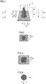
- Fig. 1 is a schematic cross sectional view of the dresser according to the first embodiment.
- Fig. 2 is a cross sectional view along an X1-X1' line in the dresser shown in Fig. 1.
- Fig. 3 is a cross sectional view along a Y1-Y1' line in the dresser shown in Fig. 1.
- Fig. 4 shows a circle having an area equal to that of a cross section of a cutting edge component 1 shown in Fig. 3 .
- Fig. 14 is a schematic cross sectional view of a point type single-point dresser of the present disclosure.
- Fig. 15 is a schematic cross sectional view of a blade type multi-point dresser of the present disclosure.
- Fig. 16 is a schematic cross sectional view of a rotary type dresser of the present disclosure.
- dresser 3 includes: a mount component 8; and a cutting edge component 1 including a portion (hereinafter, also referred to as "inserted portion") 1a inserted in mount component 8 along one insertion direction.
- Mount component 8 holds and fixes cutting edge component 1 by way of contact with cutting edge component 1.
- mount component 8 includes: a mount component substrate 2; and a joining material 7 at a region between mount component substrate 2 and cutting edge component 1.
- Joining material 7 is formed in the following manner: cutting edge component 1 is disposed in a recess of mount component substrate 2, then joining material source powder, such as sintered alloy powder, is provided in a space between mount component substrate 2 and cutting edge component 1, and sintering is performed.
- Joining material 7 is in contact with at least a portion of each of mount component substrate 2 and cutting edge component 1, and connects mount component substrate 2 and cutting edge component 1 to each other.
- dresser 3 is fixed to the machine tool or the like.
- a material of mount component substrate 2 For a material of mount component substrate 2, a carbon steel, an alloy steel, various types of steel materials, or the like can be used. As a material of joining material 7, a sintered alloy can be used.
- mount component 8 has such a shape that one recess is formed in the upper surface of a quadrangular truncated pyramid.
- Cutting edge component 1 is inserted in and held in the recess.
- a region serving as a dressing surface is a region including: the surface of mount component 8 in which the recess is formed; and the cutting edge component on the same plane as the surface in which the recess is formed, or cutting edge component 1 exposed from the recess.
- mount component 8 is not limited to the shape shown in Fig. 1 , and can be changed appropriately depending on a purpose of use of the dresser. Other exemplary shapes of the mount component will be described with reference to Fig. 14 to Fig. 16 . However, the shape of the mount component is not limited to these.
- a point type single-point dresser 43 shown in Fig. 14 includes a mount component 48 and a cutting edge component 41.
- Mount component 48 includes a mount component substrate 42 and a joining material 47.
- Mount component 48 includes: a cylindrical portion 42c long in the axial direction; and a truncated cone portion 42d continuous to one end of the cylindrical portion.
- Mount component 48 has such a shape that one recess is formed in the upper surface of truncated cone portion 42d.
- cylindrical portion 42c may have a prism shape and truncated cone portion 42d may have a truncated pyramid shape.
- a blade type multi-point dresser 53 shown in Fig. 15 includes a mount component 58 and cutting edge components 51.
- Mount component 58 includes a mount component substrate 52 and joining materials 57.
- Mount component 58 has such a shape that a plurality of recesses are formed in the upper surface of a prism. The number of recesses can be appropriately changed depending on a purpose of use of the dresser.
- a rotary type dresser shown in Fig. 16 includes a mount component 68 and cutting edge components 61.
- Mount component 68 includes a mount component substrate 62 and joining materials 67.
- Mount component 68 has such a shape that a plurality of recesses are formed in an outer circumferential surface of a roll. The number of recesses can be appropriately changed depending on a purpose of use of the dresser.
- Cutting edge component 1 includes: portion 1a inserted in mount component 8 along the one insertion direction (a direction of a downward arrow in Fig. 1 ); and an exposed portion 1b exposed from mount component 8.
- an end portion P of cutting edge component 1 at the inserted portion 1a side represents a base end portion (hereinafter, also referred to as "base end portion P") of the cutting edge component
- an end portion T of cutting edge component 1 at the exposed portion 1b side represents a front end portion (hereinafter, also referred to as "front end portion T”) of the cutting edge component.
- the term "insertion direction" refers to a direction from a dressing surface 4 toward inside of mount component 8 along a line normal to dressing surface 4, wherein dressing surface 4 represents the surface of mount component 8 in which the recess is formed.
- the insertion direction refers to a direction from dressing surface 64 toward the inside of mount component 68 along a line normal to a tangent plane of dressing surface 64.
- Portion 1a of cutting edge component 1 inserted in mount component 8 has one or more portions in each of which an area of a cross section along a line normal to the insertion direction of cutting edge component 1 is increased from the front end portion T side toward the base end portion P side in the insertion direction.
- a specific example of the shape of cutting edge component 1 will be described below.
- cutting edge component 1 has a quadrangular truncated pyramid shape.
- a cross sectional shape of cutting edge component 1 along a X1-X1' line (dressing surface 4) is a rectangular shape as shown in Fig. 2
- a cross sectional shape of cutting edge component 1 along a Y1-Y1' line is a rectangular shape having a larger area than that in Fig. 2 as shown in Fig. 3 .
- inserted portion 1a of cutting edge component 1 has one or more portions in each of which the area of the cross section along the line normal to the insertion direction is increased from the front end portion side toward the base end portion P side in the insertion direction. More specifically, in the dresser shown in Fig. 1 , the area of the cross section of inserted portion 1a of cutting edge component 1 along the line normal to the insertion direction is monotonously increased from the front end portion T side toward the base end portion P side in the insertion direction.
- the whole of inserted portion 1a of cutting edge component 1 corresponds to the "portion of the inserted portion in which the area of the cross section along the line normal to the insertion direction is monotonously increased from the front end portion side toward the base end portion side in the insertion direction" (hereinafter, also referred to as "portion with an increased cross sectional area").
- Fig. 1 shows a case where the whole of the inserted portion of the cutting edge portion correspond to the "portion with an increased cross sectional area"; however, a portion of the inserted portion of the cutting edge portion may be the "portion with an increased cross sectional area".
- the portion of the cutting edge component corresponding to the portion in which the area is monotonously increased corresponds to the "portion of the inserted portion in which the area of the cross section along the line normal to the insertion direction is monotonously increased from the front end portion side toward the base end portion side in the insertion direction” (hereinafter, also referred to as "portion with an increased cross sectional area").
- the shape of cutting edge component 1 is not limited to the quadrangular truncated pyramid, and can be a circular cone, a circular truncated cone, a pyramid, or a truncated pyramid other than the quadrangular truncated pyramid, for example.
- the cutting edge component having such a shape is inserted in mount component 8 such that the bottom surface thereof serves as base end portion P and the apex side thereof serves as front end portion T, the area of the cross section of the inserted portion of the cutting edge component along the line normal to the insertion direction is monotonously increased from the front end portion T side toward the base end portion P side in the insertion direction.
- inserted portion 1a of cutting edge component 1 has one or more portions in each of which the area of the cross section along the line normal to the insertion direction is increased from the front end portion T side toward the base end portion P side in the insertion direction, a fitted portion is formed between inserted portion 1a and mount component 8, with the result that cutting edge component 1 is less likely to be separated from mount component 8. Therefore, even when the cutting edge component is worn to become short due to use of the dresser, the cutting edge component is not separated from the mount component, whereby the dresser can have a long tool life.
- the cutting edge component and the mount component are firmly joined to each other using a sintered alloy. Accordingly, the cutting edge component is subjected to a high-temperature and high-pressure condition during joining and a difference in thermal expansion between the cutting edge component and the sintered alloy becomes large, with the result that an excessive load may be applied to the cutting edge component to cause damage therein. If there is damage inside the cutting edge component, a damage portion is exposed when the cutting edge component is worn due to use of the dresser, thus resulting in a short tool life.
- the cutting edge component is less likely to be separated from the mount component, whereby the cutting edge component can be fixed to the mount component under such conditions that the load on the cutting edge component is smaller than that in the conventional art.
- a sintering pressure can be reduced, a sintering temperature can be reduced, and a powder metal having a small thermal expansion coefficient can be used. Therefore, damage is less likely to be caused inside the cutting edge component during joining, whereby the dresser can have a long tool life.
- a ratio (L1/M1) of a length L1 and a maximum value M1 is more than or equal to 2.1, where L1 (see Fig. 1 ) represents a length of the portion of the cutting edge component inserted in the mount component along the insertion direction and M1 represents a maximum value of a diameter M (see Fig. 4 ) of a circle having an area equal to the area of the cross section along the line normal to the insertion direction in the portion of the cutting edge component inserted in the mount component.
- the dresser of the present embodiment when cutting edge component 1 is worn due to use of the dresser, cutting edge component 1 can be restored for use by polishing cutting edge component 1 and mount component 8 surrounding cutting edge component 1.
- the ratio (L1/M1) of length L1 and maximum value M1 is more than or equal to 2.1, the number of times of restoring the dresser surface is increased, whereby the dresser can have a long tool life.
- the ratio (L1/M1) is more preferably more than or equal to 2.1 and is further preferably more than or equal to 2.3.
- the upper limit value of the ratio (L1/M1) is not set particularly, the upper limit is preferably less than or equal to 8, and is more preferably less than or equal to 7 in view of manufacturing.
- length L1 is preferably more than or equal to 0.5 mm and less than or equal to 7 mm, is more preferably more than or equal to 1 mm and less than or equal to 6 mm, and is further preferably more than or equal to 1.5 mm and less than or equal to 5 mm.
- Maximum value M1 is preferably more than or equal to 0.05 mm and less than or equal to 3.5 mm, is more preferably more than or equal to 0.1 mm and less than or equal to 3.0 mm, and is further preferably more than or equal to 0.2 mm and less than or equal to 2.5 mm.
- a difference (M1-M2) between maximum value M1 and a minimum value M2 is preferably more than or equal to 0.01 mm, where M1 represents the maximum value of diameter M of the circle having the area equal to the area of the cross section along the line normal to the insertion direction in the portion of cutting edge component 1 inserted in mount component 8, and M2 represents a minimum value of diameter M of the circle having the area equal thereto. Accordingly, even when the cutting edge component is worn to become short due to use of the dresser, the cutting edge component is less likely to be separated, whereby the dresser can have a longer tool life.
- the difference (M1-M2) between M1 and M2 is more preferably more than or equal to 0.015 mm and less than or equal to 0.55 mm, and is further preferably more than or equal to 0.025 mm and less than or equal to 0.45 mm.
- a distance in the insertion direction to base end portion P of cutting edge component 1 from at least one of the portions in each of which the area of the cross section of the portion of cutting edge component 1 inserted in mount component 8 along the line normal to the insertion direction is increased from the front end portion T side toward the base end portion P side is preferably less than 1/2 of length L1. Accordingly, even when the wear of the cutting edge component is progressed, the cutting edge component is less likely to be separated from the mount component until the length of the inserted portion reaches 1/2 of L1 (region indicated by Q in Fig. 1 ), whereby the dresser can have a longer tool life.
- the area of the cross section of portion 1a of cutting edge component 1 inserted in mount component 8 along the line normal to the insertion direction preferably has a maximum value at base end portion P of inserted portion 1a. Accordingly, the cutting edge component is less likely to be separated from the mount component until the wear of the cutting edge component reaches base end portion P, whereby the dresser can have a longer tool life.
- the area of the cross section is preferably monotonously increased as a distance between the cross section and base end portion P of the inserted portion along the insertion direction is decreased. Accordingly, the cutting edge component is less likely to be separated from the mount component until the wear of the cutting edge component reaches base end portion P, whereby the dresser can have a long tool life. Further, since the mechanical strength of the cutting edge component is improved to result in an improved breakage resistance, the dresser can have a longer tool life.
- the cutting edge component may include no exposed portion, and may be constituted only of inserted portion 1a. That is, the whole of cutting edge component 1 may be inserted in mount component 8.
- Cutting edge component 1 preferably includes diamond or cubic boron nitride (hereinafter, also referred to as "cBN"). Since each of diamond and cBN has high hardness, the dresser can have an excellent wear resistance when each of these is used for the cutting edge component, whereby a longer tool life can be attained.
- cBN cubic boron nitride
- any of a single-crystal diamond, a polycrystal diamond, and a sintered diamond, which are generally available and widely applicable, can be used.
- the single-crystal diamond includes natural diamond and synthetic single-crystal diamond.
- the synthetic single-crystal diamond is readily processed into a desired shape, and is suitable as a material of the cutting edge component of the present embodiment.
- a method for producing the synthetic single-crystal diamond is not limited particularly.
- a synthetic single-crystal diamond produced using a high-pressure synthetic method or a vapor phase synthetic method can be used.
- the cutting edge component is composed of the single-crystal diamond, the surface of the cutting edge component to come into contact with a workpiece preferably corresponds to a (100) plane, a (110) plane or a (211) plane.
- the method for producing the polycrystal diamond is not limited particularly.
- a polycrystal diamond can be used which is obtained by sintering, under very high temperature and pressure, a carbon material having a graphite type layer structure without adding a sintering aid or catalyst.
- the method for producing the sintered diamond is not limited particularly.
- a sintered diamond can be used which is obtained by sintering diamond particles using a metal binder such as cobalt.
- cubic boron nitride it is possible to use: a cBN sintered material obtained by sintering cBN particles using a metal binder such as Co (cobalt) or Al (aluminum); a cBN sintered material obtained by sintering cBN particles using a ceramic binder such as TiN (titanium nitride) or TiC (titanium carbide); a binderless cBN sintered material obtained by directly converting hexagonal boron nitride into cubic boron nitride without using a catalyst and sintering it; and the like.
- a metal binder such as Co (cobalt) or Al (aluminum
- a cBN sintered material obtained by sintering cBN particles using a ceramic binder such as TiN (titanium nitride) or TiC (titanium carbide)
- a binderless cBN sintered material obtained by directly converting hexagonal boron
- Fig. 5 is a schematic cross sectional view of the dresser according to the second embodiment.
- Fig. 6 is a cross sectional view along an X2-X2' line in the dresser shown in Fig. 5.
- Fig. 7 is a cross sectional view along a Y2-Y2' line in the dresser shown in Fig. 5 .
- dresser 13 includes: a mount component 18; and a cutting edge component 11 including a portion 11a inserted in mount component 18 along one insertion direction.
- the dresser of the second embodiment can have basically the same configuration as that of the dresser of the first embodiment except for the shape of cutting edge component 11 and a corresponding shape of a recess of mount component 18. Therefore, in the description below, the shape of cutting edge component 11 will be described.
- Cutting edge component 11 includes an inserted portion 11a and an exposed portion 11b. Moreover, the cutting edge component may include no exposed portion and may be constituted only of inserted portion 11a.
- inserted portion 11a includes: a first inserted portion 11a' having a cross section along a line normal to the insertion direction, the cross section of first inserted portion 11a' having the same shape as that of the cross section of the dressing surface; and a second inserted portion 11a" that has a cross sectional area larger than that of first inserted portion 11a' and that is located at the base end portion P side. That is, inserted portion 11a of cutting edge component 11 has one portion in which the area of the cross section along the line normal to the insertion direction is increased from the front end portion T side toward the base end portion P side in the insertion direction.
- the portion with an increased cross sectional area refers to a region on a boundary surface F between the portion (first inserted portion 11a') that has a first cross sectional area and the portion (second inserted portion 11a") that is located at the base end portion side relative to the portion having the first cross sectional area and that has a second cross sectional area larger than the first cross sectional area.
- the side surface of inserted portion 11a has a protrusion at the base end portion P side in the insertion direction, thus providing a fitted portion between inserted portion 11a and mount component 18. Accordingly, cutting edge component 11 is less likely to be separated from mount component 18.
- first inserted portion 11a' is constant. Hence, even in the case where the cutting edge component is restored by polishing the cutting edge component when the cutting edge portion is worn, the same cutting edge shape as that before the restoring can be maintained. Therefore, the dresser having been restored can also maintain the same cutting performance as the cutting performance before the restoring.
- Fig. 8 is a schematic cross sectional view of the dresser according to the third embodiment.
- Fig. 9 is a cross sectional view along an X3-X3' line in the dresser shown in Fig. 8.
- Fig. 10 is a cross sectional view along a Y3-Y3' line in the dresser shown in Fig. 8 .
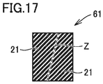
- Fig. 17 illustrates an exemplary method for manufacturing a cutting edge component used for the dresser of the third embodiment.
- dresser 23 includes: a mount component 28; and a cutting edge component 21 including a portion 21a inserted in mount component 28 along one insertion direction.
- the dresser of the third embodiment can have basically the same configuration as that of the dresser of the first embodiment except for the shape of cutting edge component 21 and a corresponding shape of a recess of mount component 28. Therefore, in the description below, the shape of cutting edge component 21 will be described.
- Cutting edge component 21 includes an inserted portion 21a and an exposed portion 21b. Moreover, the cutting edge component may include no exposed portion and may be constituted only of inserted portion 21a.
- Cutting edge component 21 can be obtained by equally dividing a cutting edge component precursor 61 into two at a position indicated by a dotted line Z, for example.
- Cutting edge component precursor 61 has a prism shape such as one shown in Fig. 17 .
- the area of inserted portion 21a of cutting edge component 21 at a cross section along a line normal to the insertion direction is monotonously increased as a distance is decreased between the cross section and base end portion P of inserted portion 21a along the insertion direction. Therefore, as with the first embodiment, even when the cutting edge component is worn to become short due to use of the dresser, the cutting edge component is not separated from the mount component, whereby the dresser can have a long tool life. Further, the cutting edge component and the mount component can be fixed under such conditions that a load on the cutting edge component is smaller than that in the conventional art, with the result that damage is less likely to be caused inside the cutting edge component during joining. Accordingly, the dresser can have a long tool life.
- Cutting edge component 21 can be obtained by equally dividing one cutting edge component precursor having a prism shape into two. Therefore, manufacturing loss of the cutting edge component is less likely to occur and therefore the dresser of the third embodiment is advantageous in terms of manufacturing cost.
- Fig. 11 is a schematic cross sectional view of the dresser according to the fourth embodiment.
- Fig. 12 is a cross sectional view along an X4-X4' line in the dresser shown in Fig. 11.
- Fig. 13 is a cross sectional view along a Y4-Y4' line in the dresser shown in Fig. 11 .
- dresser 33 includes: a mount component 38; and a cutting edge component 31 including a portion 31a inserted in mount component 38 along one insertion direction.
- the dresser of the fourth embodiment can have basically the same configuration as that of the dresser of the first embodiment except for the shape of cutting edge component 31 and a corresponding shape of a recess of mount component 38. Therefore, in the description below, the shape of cutting edge component 31 will be described.
- Cutting edge component 31 includes an inserted portion 31a and an exposed portion 31b. Moreover, the cutting edge component may include no exposed portion and may be constituted only of inserted portion 31a.
- inserted portion 31a has such a shape that a hatch 31e is formed at a portion of a quadrangular prism.
- the side surface of inserted portion 31a is provided with a recess resulting from hatch 31e, thereby providing a fitted portion between inserted portion 31a and mount component 38. Accordingly, cutting edge component 31 is less likely to be separated from mount component 38.
- the cross sectional shape of inserted portion 31a is constant except for hatch 31e.
- the shape of the cutting edge component of the dresser according to each of the first to fourth embodiments is applicable to any of a point type single-point dresser, a blade type multi-point dresser, and a rotary type dresser. Even when the cutting edge component is worn to become short due to use of each of the dressers, the cutting edge component is not separated from the mount component, whereby the dresser can have a long tool life. Further, since it is not necessary to join the cutting edge component and the mount component firmly, damage is less likely to be caused inside the cutting edge component during the joining, whereby the dresser can have a long tool life.
- the following describes an exemplary method for manufacturing a dresser according to each of the first to fifth embodiments.
- a mount component provided with a recess at a dressing surface is prepared.
- a cutting edge component is inserted into the recess of the mount component, and joining material source powder, such as sintered alloy source material powder, is provided in a space between the mount component and the cutting edge component.
- the cutting edge component has such a shape that is illustrated in each of the first to fourth embodiments, for example.
- the mount component having the cutting edge component and the joining material source powder disposed in the recess is heated at a temperature of more than or equal to 500°C and less than or equal to 700°C under a sintering pressure of 0.5 t/cm 2 for more than or equal to 5 minutes and less than or equal to 10 minutes so as to sinter the joining material source powder, thereby joining the cutting edge component and the mount component to each other. In this way, a dresser is obtained.
- the sintering is performed at a temperature of more than or equal to 800°C and less than or equal to 900°C under a sintering pressure of 1.0 to 1.5 t/cm 2 for more than or equal to 10 minutes and less than or equal to 15 minutes.
- a high-temperature and high-pressure load is applied to the cutting edge component and a thermal expansion difference becomes excessive between the cutting edge component and the joining material source powder during the sintering, with the result that damage may be caused inside the cutting edge component.
- the sintering can be performed at a lower temperature under a lower pressure for a shorter period of time than those in the conventional art, whereby damage can be suppressed from being caused inside the cutting edge component.
- Cutting edge component 41 is composed of a synthetic single-crystal diamond. A surface of cutting edge component 41 to come into contact with a workpiece corresponds to a (211) plane.
- Mount component 48 is composed of a carbon steel. For a joining material between the cutting edge component and the mount component, Fe-Cu-Sn is used.
- the inserted portion of cutting edge component 41 has a quadrangular truncated pyramid shape.
- a cross section thereof along a line normal to an insertion direction is 0.6 mm square at a front end portion T, and is 1.12 ⁇ 0.6 mm square at a base end portion P.
- a length L1 of the inserted portion of cutting edge component 41 along the insertion direction is 3 mm.
- a maximum value M1 of a diameter of a circle having an area equal to that of the cross section of the inserted portion along the line normal to the insertion direction is 0.927 mm.
- a ratio (L1/M1) of length L1 and maximum value M1 is 3.24.
- the inserted portion of the cutting edge component has a quadrangular prism shape.
- the cross sectional shape thereof along the line normal to the insertion direction is unchanged along the insertion direction.
- the inserted portion of the cutting edge component is of 0.6 mm square.
- Length L1 of the inserted portion of the cutting edge component is 3 mm.
- Maximum value M1 of the diameter of the circle having an area equal to that of the cross section of the inserted portion along the line normal to the insertion direction is 0.677 mm.
- the ratio (L1/M1) of length L1 and maximum value M1 is 4.43.
- wet type dressing was performed using each of the dressers of Example 1 and Comparative Example 1 under the following conditions: a WA grinding stone was used as a target; a grinding stone peripheral speed was set to 30 m/sec; and a cut-in amount was set to 0.05 mm.
- Cutting edge component 41 is composed of a synthetic single-crystal diamond. A surface of cutting edge component 41 to come into contact with a workpiece corresponds to a (211) plane.
- Mount component 48 is composed of a carbon steel. For a joining material between the cutting edge component and the mount component, Fe-Cu-Sn is used.
- the inserted portion of cutting edge component 41 has a quadrangular truncated pyramid shape.
- a cross section thereof along a line normal to an insertion direction is 1.1 mm square at a front end portion T, and is 1.31 ⁇ 1.1 mm square at a base end portion P.
- a length L1 of the inserted portion of cutting edge component 41 along the insertion direction is 3 mm.
- a maximum value M1 of a diameter of a circle having an area equal to that of the cross section of the inserted portion along the line normal to the insertion direction is 0.74 mm.
- a ratio (L1/M1) of length L1 and maximum value M1 is 2.21.
- the inserted portion of the cutting edge component has a quadrangular prism shape.
- the cross sectional shape thereof along the line normal to the insertion direction is unchanged along the insertion direction.
- the inserted portion of the cutting edge component is of 1.1 mm square.
- Length L1 of the inserted portion of the cutting edge component is 3 mm.
- Maximum value M1 of the diameter of the circle having an area equal to that of the cross section of the inserted portion along the line normal to the insertion direction is 1.24 mm.
- the ratio (L1/M1) of length L1 and maximum value M1 is 2.42.
- the inserted portion of the cutting edge component has a quadrangular truncated pyramid shape.
- the cross section thereof along the line normal to the insertion direction is 1.1 mm square at the front end portion, and is 1.625 ⁇ 1.1 mm square at the base end portion.
- Length L1 of the inserted portion of the cutting edge component is 3 mm.
- Maximum value M1 of the diameter of the circle having an area equal to that of the cross section of the inserted portion along the line normal to the insertion direction is 1.509 mm.
- the ratio (L1/M1) of length L1 and maximum value M1 is 1.99.
- wet type dressing was performed using each of the dressers of Example 2, Comparative Example 2 and Comparative Example 3 under the following conditions: a WA grinding stone was used as a target; a grinding stone peripheral speed was set to 30 m/sec; and a cut-in amount was set to 0.05 mm.
Landscapes
- Engineering & Computer Science (AREA)
- Mechanical Engineering (AREA)
- Grinding-Machine Dressing And Accessory Apparatuses (AREA)
- Polishing Bodies And Polishing Tools (AREA)
Abstract
Description
- The present disclosure relates to a dresser. The present application claims a priority based on Japanese Patent Application No.
2018-076822 filed on April 12, 2018 - Conventionally, diamond has been used as a material for dressers. For example, Japanese Patent Laying-Open No.
8-229818 - In such a diamond dresser, a front end portion (portion exposed from the substrate) of the single-crystal columnar diamond serving as a cutting edge is gradually worn due to use thereof. The life thereof is expired in the following manner: a diamond portion ceases to exist; or the diamond portion falls off from the substrate before the diamond portion ceases to exist.
- PTL 1: Japanese Patent Laying-Open No.
8-229818 - A dresser according to the present disclosure includes:
- a mount component; and
- a cutting edge component inserted in the mount component at a base end portion side, the cutting edge component being fixed to the mount component by bringing, into contact with the mount component, a portion of the cutting edge component inserted in the mount component, the cutting edge component being exposed from the mount component at a front end portion side to form a cutting edge, wherein
- the portion of the cutting edge component inserted in the mount component has one or more portions in each of which an area of a cross section along a line normal to an insertion direction of the cutting edge component is increased from the front end portion side toward the base end portion side in the insertion direction, and
- a ratio L1/M1 of a length L1 and a maximum value M1 is more than or equal to 2.1, where L1 represents a length of the portion of the cutting edge component inserted in the mount component and M1 represents a maximum value of a diameter of a circle having an area equal to the area of the cross section along the line normal to the insertion direction in the portion of the cutting edge component inserted in the mount component.
-
-
Fig. 1 is a schematic cross sectional view of a dresser according to a first embodiment. -
Fig. 2 is a cross sectional view along an X1-X1' line in the dresser shown inFig. 1 . -
Fig. 3 is a cross sectional view along a Y1-Y1' line in the dresser shown inFig. 1 . -
Fig. 4 shows a circle having an area equal to that of a cross section of a cutting edge component shown inFig. 3 . -
Fig. 5 is a schematic cross sectional view of a dresser according to a second embodiment. -
Fig. 6 is a cross sectional view along an X2-X2' line in the dresser shown inFig. 5 . -
Fig. 7 is a cross sectional view along a Y2-Y2' line in the dresser shown inFig. 5 . -
Fig. 8 is a schematic cross sectional view of a dresser according to a third embodiment. -
Fig. 9 is a cross sectional view along an X3-X3' line in the dresser shown inFig. 8 . -
Fig. 10 is a cross sectional view along a Y3-Y3' line in the dresser shown inFig. 8 . -
Fig. 11 is a schematic cross sectional view of a dresser according to a fourth embodiment. -
Fig. 12 is a cross sectional view along an X4-X4' line in the dresser shown inFig. 11 . -
Fig. 13 is a cross sectional view along a Y4-Y4' line in the dresser shown inFig. 11 . -
Fig. 14 is a schematic cross sectional view of a point type single-point dresser of the present disclosure. -
Fig. 15 is a schematic cross sectional view of a blade type multi-point dresser of the present disclosure. -
Fig. 16 is a schematic cross sectional view of a rotary type dresser of the present disclosure. -
Fig. 17 illustrates an exemplary method for manufacturing a cutting edge component used for the dresser according to the third embodiment. - Shape and area of the columnar diamond in Japanese Patent Laying-Open No.
8-229818 - Thus, the present object is to provide a dresser having a long tool life.
- The dresser according to the above-described embodiment can have a long tool life.
- First, embodiments of the present disclosure are listed and described.
- (1) A dresser according to the present disclosure includes:
- a mount component; and
- a cutting edge component inserted in the mount component at a base end portion side, the cutting edge component being fixed to the mount component by bringing, into contact with the mount component, a portion of the cutting edge component inserted in the mount component, the cutting edge component being exposed from the mount component at a front end portion side to form a cutting edge, wherein
- the portion of the cutting edge component inserted in the mount component has one or more portions in each of which an area of a cross section along a line normal to an insertion direction of the cutting edge component is increased from the front end portion side toward the base end portion side in the insertion direction, and
- a ratio L1/M1 of a length L1 and a maximum value M1 (hereinafter, also referred to as "(L1/M1)") is more than or equal to 2.1, where L1 represents a length of the portion of the cutting edge component inserted in the mount component and M1 represents a maximum value of a diameter of a circle having an area equal to the area of the cross section along the line normal to the insertion direction in the portion of the cutting edge component inserted in the mount component.
This dresser can have a long tool life. - (2) Preferably, a distance in the insertion direction to the base end portion of the cutting edge component from at least one of the portions in each of which the area of the cross section of the portion of the cutting edge component inserted in the mount component along the line normal to the insertion direction is increased from the front end portion side toward the base end portion side is less than 1/2 of the length L1, where L1 represents the length of the portion of the cutting edge component inserted in the mount component in the insertion direction. Accordingly, even when the cutting edge component is worn to become short due to use of the dresser, the cutting edge component is less likely to be separated, whereby the dresser can have a longer tool life.
- (3) Preferably, a difference M1-M2 between the maximum value M1 and a minimum value M2 (hereinafter, also referred to as "(M1-M2)") is more than or equal to 0.01 mm, where M1 represents the maximum value of the diameter of the circle having the area equal to the area of the cross section along the line normal to the insertion direction in the portion of the cutting edge component inserted in the mount component, and M2 represents a minimum value of the diameter of the circle having the area equal. Accordingly, even when the cutting edge component is worn to become short due to use of the dresser, the cutting edge component is less likely to be separated, whereby the dresser can have a longer tool life.
- (4) Preferably, the cutting edge component includes diamond or cubic boron nitride. Since each of diamond and cBN has a high hardness, the dresser can have an excellent wear resistance when each of these is used for the cutting edge component, whereby a longer tool life can be attained.
- (5) Preferably, the cutting edge component is composed of a single-crystal diamond, and a surface of the cutting edge component to come into contact with a workpiece corresponds to a (100) plane, a (110) plane or a (211) plane. Since the (100) plane, the (110) plane and the (211) plane of diamond provides excellent wear resistance, the dresser can have a excellent wear resistance when each of these is used for the surface to come into contact with a workpiece, whereby a longer tool life can be attained.
- (6) Preferably, the area of the cross section of the portion of the cutting edge component inserted in the mount component along the line normal to the insertion direction has a maximum value at the base end portion of the portion of the cutting edge component inserted in the mount component. Accordingly, even when the cutting edge component is worn to become short due to use of the dresser, the cutting edge component is less likely to be separated, whereby the dresser can have a longer tool life.
- (7) Preferably, the area of the cross section is monotonously increased as a distance is decreased between the cross section and the base end portion of the the portion of the cutting edge component inserted in the mount component along the insertion direction. Accordingly, even when the cutting edge component is worn to become short due to use of the dresser, the cutting edge component is less likely to be separated and is less likely to be broken, whereby the dresser can have a longer tool life.
- (8) Preferably, the area of the cross section of the portion of the cutting edge component inserted in the mount component along the line normal to the insertion direction is once decreased and then increased as a distance is decreased between the cross section and the base end portion of the the portion of the cutting edge component inserted in the mount component along the insertion direction. Accordingly, even when the cutting edge component is worn to become short due to use of the dresser, the cutting edge component is less likely to be separated, whereby the dresser can have a longer tool life.
- (9) Preferably, the dresser is a point type single-point dresser, a blade type multi-point dresser, or a rotary type dresser. Even when the cutting edge component is worn to become short due to use of each of these dressers, the cutting edge component is less likely to be separated, whereby the dresser can have a longer tool life.
- The following describes a specific example of a dresser of the present disclosure with reference to figures.
- The same reference characters indicate the same or equivalent portions in the figures. Dimensions, such as length, width, thickness, and depth, are appropriately changed for clarity and simplification of the figures and do not represent actual dimensions.
- The following describes a dresser according to a first embodiment with reference to
Fig. 1 to Fig. 4 andFig. 14 to Fig. 16 .Fig. 1 is a schematic cross sectional view of the dresser according to the first embodiment.Fig. 2 is a cross sectional view along an X1-X1' line in the dresser shown inFig. 1. Fig. 3 is a cross sectional view along a Y1-Y1' line in the dresser shown inFig. 1. Fig. 4 shows a circle having an area equal to that of a cross section of acutting edge component 1 shown inFig. 3 .Fig. 14 is a schematic cross sectional view of a point type single-point dresser of the present disclosure.Fig. 15 is a schematic cross sectional view of a blade type multi-point dresser of the present disclosure.Fig. 16 is a schematic cross sectional view of a rotary type dresser of the present disclosure. - As shown in
Fig. 1 ,dresser 3 includes: amount component 8; and acutting edge component 1 including a portion (hereinafter, also referred to as "inserted portion") 1a inserted inmount component 8 along one insertion direction. -
Mount component 8 holds and fixes cuttingedge component 1 by way of contact with cuttingedge component 1. As shown inFig. 1 ,mount component 8 includes: a mount component substrate 2; and a joiningmaterial 7 at a region between mount component substrate 2 andcutting edge component 1. Joiningmaterial 7 is formed in the following manner: cuttingedge component 1 is disposed in a recess of mount component substrate 2, then joining material source powder, such as sintered alloy powder, is provided in a space between mount component substrate 2 andcutting edge component 1, and sintering is performed. Joiningmaterial 7 is in contact with at least a portion of each of mount component substrate 2 andcutting edge component 1, and connects mount component substrate 2 andcutting edge component 1 to each other. By fixingmount component 8 to a machine tool (not shown) or the like,dresser 3 is fixed to the machine tool or the like. - For a material of mount component substrate 2, a carbon steel, an alloy steel, various types of steel materials, or the like can be used. As a material of joining
material 7, a sintered alloy can be used. - In
dresser 3 shown inFig. 1 ,mount component 8 has such a shape that one recess is formed in the upper surface of a quadrangular truncated pyramid. Cuttingedge component 1 is inserted in and held in the recess. A region serving as a dressing surface is a region including: the surface ofmount component 8 in which the recess is formed; and the cutting edge component on the same plane as the surface in which the recess is formed, or cuttingedge component 1 exposed from the recess. - The shape of
mount component 8 is not limited to the shape shown inFig. 1 , and can be changed appropriately depending on a purpose of use of the dresser. Other exemplary shapes of the mount component will be described with reference toFig. 14 to Fig. 16 . However, the shape of the mount component is not limited to these. - A point type single-
point dresser 43 shown inFig. 14 includes amount component 48 and acutting edge component 41.Mount component 48 includes amount component substrate 42 and a joiningmaterial 47.Mount component 48 includes: acylindrical portion 42c long in the axial direction; and atruncated cone portion 42d continuous to one end of the cylindrical portion.Mount component 48 has such a shape that one recess is formed in the upper surface oftruncated cone portion 42d. In the case of the point type single-point dresser,cylindrical portion 42c may have a prism shape andtruncated cone portion 42d may have a truncated pyramid shape. - A blade type
multi-point dresser 53 shown inFig. 15 includes amount component 58 andcutting edge components 51.Mount component 58 includes amount component substrate 52 and joiningmaterials 57.Mount component 58 has such a shape that a plurality of recesses are formed in the upper surface of a prism. The number of recesses can be appropriately changed depending on a purpose of use of the dresser. - A rotary type dresser shown in
Fig. 16 includes amount component 68 andcutting edge components 61.Mount component 68 includes amount component substrate 62 and joiningmaterials 67.Mount component 68 has such a shape that a plurality of recesses are formed in an outer circumferential surface of a roll. The number of recesses can be appropriately changed depending on a purpose of use of the dresser. - Cutting
edge component 1 includes:portion 1a inserted inmount component 8 along the one insertion direction (a direction of a downward arrow inFig. 1 ); and an exposedportion 1b exposed frommount component 8. In the present specification, an end portion P of cuttingedge component 1 at the insertedportion 1a side represents a base end portion (hereinafter, also referred to as "base end portion P") of the cutting edge component, and an end portion T of cuttingedge component 1 at the exposedportion 1b side represents a front end portion (hereinafter, also referred to as "front end portion T") of the cutting edge component. - Here, the term "insertion direction" refers to a direction from a
dressing surface 4 toward inside ofmount component 8 along a line normal to dressingsurface 4, wherein dressingsurface 4 represents the surface ofmount component 8 in which the recess is formed. As shown inFig. 16 , when a dressingsurface 64 is a curved surface, the insertion direction refers to a direction from dressingsurface 64 toward the inside ofmount component 68 along a line normal to a tangent plane of dressingsurface 64. -
Portion 1a of cuttingedge component 1 inserted inmount component 8 has one or more portions in each of which an area of a cross section along a line normal to the insertion direction of cuttingedge component 1 is increased from the front end portion T side toward the base end portion P side in the insertion direction. A specific example of the shape of cuttingedge component 1 will be described below. - In
dresser 3 shown inFig. 1 , cuttingedge component 1 has a quadrangular truncated pyramid shape. A cross sectional shape of cuttingedge component 1 along a X1-X1' line (dressing surface 4) is a rectangular shape as shown inFig. 2 , and a cross sectional shape of cuttingedge component 1 along a Y1-Y1' line is a rectangular shape having a larger area than that inFig. 2 as shown inFig. 3 . - Therefore, in
dresser 3 shown inFig. 1 , insertedportion 1a of cuttingedge component 1 has one or more portions in each of which the area of the cross section along the line normal to the insertion direction is increased from the front end portion side toward the base end portion P side in the insertion direction. More specifically, in the dresser shown inFig. 1 , the area of the cross section of insertedportion 1a of cuttingedge component 1 along the line normal to the insertion direction is monotonously increased from the front end portion T side toward the base end portion P side in the insertion direction. The whole of insertedportion 1a of cuttingedge component 1 corresponds to the "portion of the inserted portion in which the area of the cross section along the line normal to the insertion direction is monotonously increased from the front end portion side toward the base end portion side in the insertion direction" (hereinafter, also referred to as "portion with an increased cross sectional area"). -
Fig. 1 shows a case where the whole of the inserted portion of the cutting edge portion correspond to the "portion with an increased cross sectional area"; however, a portion of the inserted portion of the cutting edge portion may be the "portion with an increased cross sectional area". For example, when the inserted portion of the cutting edge component has a portion in which the area of the cross section along the line normal to the insertion direction is monotonously increased from the front end portion T side toward the base end portion P side in the insertion direction, the portion of the cutting edge component corresponding to the portion in which the area is monotonously increased corresponds to the "portion of the inserted portion in which the area of the cross section along the line normal to the insertion direction is monotonously increased from the front end portion side toward the base end portion side in the insertion direction" (hereinafter, also referred to as "portion with an increased cross sectional area"). - The shape of cutting
edge component 1 is not limited to the quadrangular truncated pyramid, and can be a circular cone, a circular truncated cone, a pyramid, or a truncated pyramid other than the quadrangular truncated pyramid, for example. When the cutting edge component having such a shape is inserted inmount component 8 such that the bottom surface thereof serves as base end portion P and the apex side thereof serves as front end portion T, the area of the cross section of the inserted portion of the cutting edge component along the line normal to the insertion direction is monotonously increased from the front end portion T side toward the base end portion P side in the insertion direction. - When inserted
portion 1a of cuttingedge component 1 has one or more portions in each of which the area of the cross section along the line normal to the insertion direction is increased from the front end portion T side toward the base end portion P side in the insertion direction, a fitted portion is formed between insertedportion 1a andmount component 8, with the result that cuttingedge component 1 is less likely to be separated frommount component 8. Therefore, even when the cutting edge component is worn to become short due to use of the dresser, the cutting edge component is not separated from the mount component, whereby the dresser can have a long tool life. - Conventionally, in order to prevent the cutting edge component from being separated from the mount component, the cutting edge component and the mount component are firmly joined to each other using a sintered alloy. Accordingly, the cutting edge component is subjected to a high-temperature and high-pressure condition during joining and a difference in thermal expansion between the cutting edge component and the sintered alloy becomes large, with the result that an excessive load may be applied to the cutting edge component to cause damage therein. If there is damage inside the cutting edge component, a damage portion is exposed when the cutting edge component is worn due to use of the dresser, thus resulting in a short tool life.
- In the dresser of the present embodiment, the cutting edge component is less likely to be separated from the mount component, whereby the cutting edge component can be fixed to the mount component under such conditions that the load on the cutting edge component is smaller than that in the conventional art. Specifically, a sintering pressure can be reduced, a sintering temperature can be reduced, and a powder metal having a small thermal expansion coefficient can be used. Therefore, damage is less likely to be caused inside the cutting edge component during joining, whereby the dresser can have a long tool life.
- A ratio (L1/M1) of a length L1 and a maximum value M1 is more than or equal to 2.1, where L1 (see
Fig. 1 ) represents a length of the portion of the cutting edge component inserted in the mount component along the insertion direction and M1 represents a maximum value of a diameter M (seeFig. 4 ) of a circle having an area equal to the area of the cross section along the line normal to the insertion direction in the portion of the cutting edge component inserted in the mount component. - In the dresser of the present embodiment, when cutting
edge component 1 is worn due to use of the dresser, cuttingedge component 1 can be restored for use by polishingcutting edge component 1 andmount component 8 surroundingcutting edge component 1. When the ratio (L1/M1) of length L1 and maximum value M1 is more than or equal to 2.1, the number of times of restoring the dresser surface is increased, whereby the dresser can have a long tool life. The ratio (L1/M1) is more preferably more than or equal to 2.1 and is further preferably more than or equal to 2.3.
Although the upper limit value of the ratio (L1/M1) is not set particularly, the upper limit is preferably less than or equal to 8, and is more preferably less than or equal to 7 in view of manufacturing. - For example, length L1 is preferably more than or equal to 0.5 mm and less than or equal to 7 mm, is more preferably more than or equal to 1 mm and less than or equal to 6 mm, and is further preferably more than or equal to 1.5 mm and less than or equal to 5 mm.
- Maximum value M1 is preferably more than or equal to 0.05 mm and less than or equal to 3.5 mm, is more preferably more than or equal to 0.1 mm and less than or equal to 3.0 mm, and is further preferably more than or equal to 0.2 mm and less than or equal to 2.5 mm.
- A difference (M1-M2) between maximum value M1 and a minimum value M2 is preferably more than or equal to 0.01 mm, where M1 represents the maximum value of diameter M of the circle having the area equal to the area of the cross section along the line normal to the insertion direction in the portion of cutting
edge component 1 inserted inmount component 8, and M2 represents a minimum value of diameter M of the circle having the area equal thereto. Accordingly, even when the cutting edge component is worn to become short due to use of the dresser, the cutting edge component is less likely to be separated, whereby the dresser can have a longer tool life. - The difference (M1-M2) between M1 and M2 is more preferably more than or equal to 0.015 mm and less than or equal to 0.55 mm, and is further preferably more than or equal to 0.025 mm and less than or equal to 0.45 mm.
- As shown in
Fig. 1 , when L1 represents the length ofportion 1a of cuttingedge component 1 inserted inmount component 8 in the insertion direction, a distance in the insertion direction to base end portion P of cuttingedge component 1 from at least one of the portions in each of which the area of the cross section of the portion of cuttingedge component 1 inserted inmount component 8 along the line normal to the insertion direction is increased from the front end portion T side toward the base end portion P side is preferably less than 1/2 of length L1. Accordingly, even when the wear of the cutting edge component is progressed, the cutting edge component is less likely to be separated from the mount component until the length of the inserted portion reaches 1/2 of L1 (region indicated by Q inFig. 1 ), whereby the dresser can have a longer tool life. - As shown in
Fig. 1 , the area of the cross section ofportion 1a of cuttingedge component 1 inserted inmount component 8 along the line normal to the insertion direction preferably has a maximum value at base end portion P of insertedportion 1a. Accordingly, the cutting edge component is less likely to be separated from the mount component until the wear of the cutting edge component reaches base end portion P, whereby the dresser can have a longer tool life. - As shown in
Fig. 1 , the area of the cross section is preferably monotonously increased as a distance between the cross section and base end portion P of the inserted portion along the insertion direction is decreased. Accordingly, the cutting edge component is less likely to be separated from the mount component until the wear of the cutting edge component reaches base end portion P, whereby the dresser can have a long tool life. Further, since the mechanical strength of the cutting edge component is improved to result in an improved breakage resistance, the dresser can have a longer tool life. - The cutting edge component may include no exposed portion, and may be constituted only of inserted
portion 1a. That is, the whole of cuttingedge component 1 may be inserted inmount component 8. - Cutting
edge component 1 preferably includes diamond or cubic boron nitride (hereinafter, also referred to as "cBN"). Since each of diamond and cBN has high hardness, the dresser can have an excellent wear resistance when each of these is used for the cutting edge component, whereby a longer tool life can be attained. - As the diamond, any of a single-crystal diamond, a polycrystal diamond, and a sintered diamond, which are generally available and widely applicable, can be used.
- Examples of the single-crystal diamond includes natural diamond and synthetic single-crystal diamond. The synthetic single-crystal diamond is readily processed into a desired shape, and is suitable as a material of the cutting edge component of the present embodiment. A method for producing the synthetic single-crystal diamond is not limited particularly. For example, a synthetic single-crystal diamond produced using a high-pressure synthetic method or a vapor phase synthetic method can be used. When the cutting edge component is composed of the single-crystal diamond, the surface of the cutting edge component to come into contact with a workpiece preferably corresponds to a (100) plane, a (110) plane or a (211) plane.
- The method for producing the polycrystal diamond is not limited particularly. For example, a polycrystal diamond can be used which is obtained by sintering, under very high temperature and pressure, a carbon material having a graphite type layer structure without adding a sintering aid or catalyst.
- The method for producing the sintered diamond is not limited particularly. For example, a sintered diamond can be used which is obtained by sintering diamond particles using a metal binder such as cobalt.
- As the cubic boron nitride, it is possible to use: a cBN sintered material obtained by sintering cBN particles using a metal binder such as Co (cobalt) or Al (aluminum); a cBN sintered material obtained by sintering cBN particles using a ceramic binder such as TiN (titanium nitride) or TiC (titanium carbide); a binderless cBN sintered material obtained by directly converting hexagonal boron nitride into cubic boron nitride without using a catalyst and sintering it; and the like.
- The following describes a dresser according to a second embodiment with reference to
Fig. 5 to Fig. 7. Fig. 5 is a schematic cross sectional view of the dresser according to the second embodiment.Fig. 6 is a cross sectional view along an X2-X2' line in the dresser shown inFig. 5. Fig. 7 is a cross sectional view along a Y2-Y2' line in the dresser shown inFig. 5 . - As shown in
Fig. 5 ,dresser 13 includes: amount component 18; and acutting edge component 11 including aportion 11a inserted inmount component 18 along one insertion direction. The dresser of the second embodiment can have basically the same configuration as that of the dresser of the first embodiment except for the shape of cuttingedge component 11 and a corresponding shape of a recess ofmount component 18. Therefore, in the description below, the shape of cuttingedge component 11 will be described. - Cutting
edge component 11 includes an insertedportion 11a and an exposedportion 11b. Moreover, the cutting edge component may include no exposed portion and may be constituted only of insertedportion 11a. - In
cutting edge component 11, insertedportion 11a includes: a first insertedportion 11a' having a cross section along a line normal to the insertion direction, the cross section of first insertedportion 11a' having the same shape as that of the cross section of the dressing surface; and a second insertedportion 11a" that has a cross sectional area larger than that of first insertedportion 11a' and that is located at the base end portion P side. That is, insertedportion 11a of cuttingedge component 11 has one portion in which the area of the cross section along the line normal to the insertion direction is increased from the front end portion T side toward the base end portion P side in the insertion direction. When the cross sectional area is increased intermittently rather than continuously as in the present embodiment, the portion with an increased cross sectional area refers to a region on a boundary surface F between the portion (first insertedportion 11a') that has a first cross sectional area and the portion (second insertedportion 11a") that is located at the base end portion side relative to the portion having the first cross sectional area and that has a second cross sectional area larger than the first cross sectional area. - In the second embodiment, the side surface of inserted
portion 11a has a protrusion at the base end portion P side in the insertion direction, thus providing a fitted portion between insertedportion 11a andmount component 18. Accordingly, cuttingedge component 11 is less likely to be separated frommount component 18. - Furthermore, the cross sectional shape of first inserted
portion 11a' is constant. Hence, even in the case where the cutting edge component is restored by polishing the cutting edge component when the cutting edge portion is worn, the same cutting edge shape as that before the restoring can be maintained. Therefore, the dresser having been restored can also maintain the same cutting performance as the cutting performance before the restoring. - The following describes a dresser according to a third embodiment with reference to
Fig. 8 to Fig. 10 andFig. 17 .Fig. 8 is a schematic cross sectional view of the dresser according to the third embodiment.Fig. 9 is a cross sectional view along an X3-X3' line in the dresser shown inFig. 8. Fig. 10 is a cross sectional view along a Y3-Y3' line in the dresser shown inFig. 8 .Fig. 17 illustrates an exemplary method for manufacturing a cutting edge component used for the dresser of the third embodiment. - As shown in
Fig. 8 ,dresser 23 includes: amount component 28; and acutting edge component 21 including aportion 21a inserted inmount component 28 along one insertion direction. The dresser of the third embodiment can have basically the same configuration as that of the dresser of the first embodiment except for the shape of cuttingedge component 21 and a corresponding shape of a recess ofmount component 28. Therefore, in the description below, the shape of cuttingedge component 21 will be described. - Cutting
edge component 21 includes an insertedportion 21a and an exposedportion 21b. Moreover, the cutting edge component may include no exposed portion and may be constituted only of insertedportion 21a. - Cutting
edge component 21 can be obtained by equally dividing a cuttingedge component precursor 61 into two at a position indicated by a dotted line Z, for example. Cuttingedge component precursor 61 has a prism shape such as one shown inFig. 17 . - The area of inserted
portion 21a of cuttingedge component 21 at a cross section along a line normal to the insertion direction is monotonously increased as a distance is decreased between the cross section and base end portion P of insertedportion 21a along the insertion direction. Therefore, as with the first embodiment, even when the cutting edge component is worn to become short due to use of the dresser, the cutting edge component is not separated from the mount component, whereby the dresser can have a long tool life. Further, the cutting edge component and the mount component can be fixed under such conditions that a load on the cutting edge component is smaller than that in the conventional art, with the result that damage is less likely to be caused inside the cutting edge component during joining. Accordingly, the dresser can have a long tool life. - Cutting
edge component 21 can be obtained by equally dividing one cutting edge component precursor having a prism shape into two. Therefore, manufacturing loss of the cutting edge component is less likely to occur and therefore the dresser of the third embodiment is advantageous in terms of manufacturing cost. - The following describes a dresser according to a fourth embodiment with reference to
Fig. 11 to Fig. 13. Fig. 11 is a schematic cross sectional view of the dresser according to the fourth embodiment.Fig. 12 is a cross sectional view along an X4-X4' line in the dresser shown inFig. 11. Fig. 13 is a cross sectional view along a Y4-Y4' line in the dresser shown inFig. 11 . - As shown in
Fig. 11 ,dresser 33 includes: amount component 38; and acutting edge component 31 including aportion 31a inserted inmount component 38 along one insertion direction. The dresser of the fourth embodiment can have basically the same configuration as that of the dresser of the first embodiment except for the shape of cuttingedge component 31 and a corresponding shape of a recess ofmount component 38. Therefore, in the description below, the shape of cuttingedge component 31 will be described. - Cutting
edge component 31 includes an insertedportion 31a and an exposedportion 31b. Moreover, the cutting edge component may include no exposed portion and may be constituted only of insertedportion 31a. - The area of the cross section of the portion of cutting
edge component 31 inserted inmount component 38 along the line normal to the insertion direction is once decreased and then increased as a distance is decreased between the cross section and base end portion P of insertedportion 31a along the insertion direction. Specifically, insertedportion 31a has such a shape that ahatch 31e is formed at a portion of a quadrangular prism. The side surface of insertedportion 31a is provided with a recess resulting fromhatch 31e, thereby providing a fitted portion between insertedportion 31a andmount component 38. Accordingly, cuttingedge component 31 is less likely to be separated frommount component 38. - Furthermore, the cross sectional shape of inserted
portion 31a is constant except forhatch 31e. Hence, even in the case where the cutting edge component is restored by polishing the cutting edge component when the cutting edge portion is worn, the same cutting edge shape as that before the restoring can be maintained. Therefore, the dresser having been restored can also maintain the same cutting performance as the cutting performance before the restoring. - The shape of the cutting edge component of the dresser according to each of the first to fourth embodiments is applicable to any of a point type single-point dresser, a blade type multi-point dresser, and a rotary type dresser. Even when the cutting edge component is worn to become short due to use of each of the dressers, the cutting edge component is not separated from the mount component, whereby the dresser can have a long tool life. Further, since it is not necessary to join the cutting edge component and the mount component firmly, damage is less likely to be caused inside the cutting edge component during the joining, whereby the dresser can have a long tool life.
- The following describes an exemplary method for manufacturing a dresser according to each of the first to fifth embodiments.
- A mount component provided with a recess at a dressing surface is prepared. A cutting edge component is inserted into the recess of the mount component, and joining material source powder, such as sintered alloy source material powder, is provided in a space between the mount component and the cutting edge component. The cutting edge component has such a shape that is illustrated in each of the first to fourth embodiments, for example.
- The mount component having the cutting edge component and the joining material source powder disposed in the recess is heated at a temperature of more than or equal to 500°C and less than or equal to 700°C under a sintering pressure of 0.5 t/cm2 for more than or equal to 5 minutes and less than or equal to 10 minutes so as to sinter the joining material source powder, thereby joining the cutting edge component and the mount component to each other. In this way, a dresser is obtained.
- In the conventional art, in order to avoid the cutting edge component from being separated from the mount component, the sintering is performed at a temperature of more than or equal to 800°C and less than or equal to 900°C under a sintering pressure of 1.0 to 1.5 t/cm2 for more than or equal to 10 minutes and less than or equal to 15 minutes. In such a sintering condition, a high-temperature and high-pressure load is applied to the cutting edge component and a thermal expansion difference becomes excessive between the cutting edge component and the joining material source powder during the sintering, with the result that damage may be caused inside the cutting edge component. According to the present embodiment, the sintering can be performed at a lower temperature under a lower pressure for a shorter period of time than those in the conventional art, whereby damage can be suppressed from being caused inside the cutting edge component.
- The following describes the present embodiment more specifically by way of examples. However, the present embodiment is not limited by these examples.
- In an Example 1, a point type single-point dresser having a shape shown in
Fig. 14 is produced. Cuttingedge component 41 is composed of a synthetic single-crystal diamond. A surface of cuttingedge component 41 to come into contact with a workpiece corresponds to a (211) plane.Mount component 48 is composed of a carbon steel. For a joining material between the cutting edge component and the mount component, Fe-Cu-Sn is used. - The inserted portion of cutting
edge component 41 has a quadrangular truncated pyramid shape. A cross section thereof along a line normal to an insertion direction is 0.6 mm square at a front end portion T, and is 1.12×0.6 mm square at a base end portion P. A length L1 of the inserted portion of cuttingedge component 41 along the insertion direction is 3 mm. A maximum value M1 of a diameter of a circle having an area equal to that of the cross section of the inserted portion along the line normal to the insertion direction is 0.927 mm. A ratio (L1/M1) of length L1 and maximum value M1 is 3.24. - In a Comparative Example 1, a point type single-point dresser having the same configuration as that of Example 1 except for the shape of the cutting edge component is produced.
- The inserted portion of the cutting edge component has a quadrangular prism shape. The cross sectional shape thereof along the line normal to the insertion direction is unchanged along the insertion direction. The inserted portion of the cutting edge component is of 0.6 mm square. Length L1 of the inserted portion of the cutting edge component is 3 mm. Maximum value M1 of the diameter of the circle having an area equal to that of the cross section of the inserted portion along the line normal to the insertion direction is 0.677 mm. The ratio (L1/M1) of length L1 and maximum value M1 is 4.43.
- For evaluation of tool lives, wet type dressing was performed using each of the dressers of Example 1 and Comparative Example 1 under the following conditions: a WA grinding stone was used as a target; a grinding stone peripheral speed was set to 30 m/sec; and a cut-in amount was set to 0.05 mm.
- In the dresser of Example 1, even when a wear amount of the cutting edge component was 2 mm, the dressing could be performed normally without the cutting edge component being separated from the mount component.
- In the dresser of Comparative Example 1, when a wear amount of the cutting edge component was 2 mm, the cutting edge component was separated from the mount component, with the result that the dressing could not be performed.
- It was confirmed that the tool life of the dresser of Example 1 is longer than that of the dresser of Comparative Example 1.
- In an Example 2, a point type single-point dresser having a shape shown in
Fig. 14 is produced. Cuttingedge component 41 is composed of a synthetic single-crystal diamond. A surface of cuttingedge component 41 to come into contact with a workpiece corresponds to a (211) plane.Mount component 48 is composed of a carbon steel. For a joining material between the cutting edge component and the mount component, Fe-Cu-Sn is used. - The inserted portion of cutting
edge component 41 has a quadrangular truncated pyramid shape. A cross section thereof along a line normal to an insertion direction is 1.1 mm square at a front end portion T, and is 1.31×1.1 mm square at a base end portion P. A length L1 of the inserted portion of cuttingedge component 41 along the insertion direction is 3 mm. A maximum value M1 of a diameter of a circle having an area equal to that of the cross section of the inserted portion along the line normal to the insertion direction is 0.74 mm. A ratio (L1/M1) of length L1 and maximum value M1 is 2.21. - In a Comparative Example 2, a point type single-point dresser having the same configuration as that of Example 2 except for the shape of the cutting edge component is produced.
- The inserted portion of the cutting edge component has a quadrangular prism shape. The cross sectional shape thereof along the line normal to the insertion direction is unchanged along the insertion direction. The inserted portion of the cutting edge component is of 1.1 mm square. Length L1 of the inserted portion of the cutting edge component is 3 mm. Maximum value M1 of the diameter of the circle having an area equal to that of the cross section of the inserted portion along the line normal to the insertion direction is 1.24 mm. The ratio (L1/M1) of length L1 and maximum value M1 is 2.42.
- In a Comparative Example 3, a point type single-point dresser having the same configuration as that of Example 2 except for the shape of the cutting edge component is produced.
- The inserted portion of the cutting edge component has a quadrangular truncated pyramid shape. The cross section thereof along the line normal to the insertion direction is 1.1 mm square at the front end portion, and is 1.625×1.1 mm square at the base end portion. Length L1 of the inserted portion of the cutting edge component is 3 mm. Maximum value M1 of the diameter of the circle having an area equal to that of the cross section of the inserted portion along the line normal to the insertion direction is 1.509 mm. The ratio (L1/M1) of length L1 and maximum value M1 is 1.99.
- For evaluation of tool lives, wet type dressing was performed using each of the dressers of Example 2, Comparative Example 2 and Comparative Example 3 under the following conditions: a WA grinding stone was used as a target; a grinding stone peripheral speed was set to 30 m/sec; and a cut-in amount was set to 0.05 mm.
- In the dresser of Example 2, even when a wear amount of the cutting edge component was 2.2 mm, the dressing could be performed normally without the cutting edge component being separated from the mount component.
- In the dresser of Comparative Example 2, when a wear amount of the cutting edge component was 2.2 mm, the cutting edge component was separated from the mount component, with the result that the dressing could not be performed.
- In the dresser of Comparative Example 3, when a wear amount of the cutting edge component was 2.2 mm, the surface of the WA grinding stone serving as the target was melted to adhere thereto, with the result that the cutting edge portion fell off due to breakage. Accordingly, the dressing could not be continued.
- It was confirmed that the tool life of the dresser of Example 2 is longer than that of the dresser of each of Comparative Examples 2 and 3.
- Heretofore, the embodiments and examples of the present invention have been illustrated, but it has been initially expected to appropriately combine the configurations of the embodiments and examples and modify them in various manners.
- The embodiments and examples disclosed herein are illustrative and non-restrictive in any respect. The scope of the present invention is defined by the terms of the claims, rather than the embodiments and examples described above, and is intended to include any modifications within the scope and meaning equivalent to the terms of the claims.
- 1, 11, 21, 31, 41, 51, 61: cutting edge component; 2, 12, 22, 32, 42, 52, 62: mount component substrate; 3, 13, 23, 33: dresser; 7, 17, 27, 37, 47, 57, 67: joining material; 8, 18, 28, 38, 48, 58, 68: mount component; 43: point type single-point dresser; 53: blade type multi-point dresser; 63: rotary type dresser; P: base end portion; T: front end portion.
Claims (9)
- A dresser comprising:a mount component; anda cutting edge component inserted in the mount component at a base end portion side, the cutting edge component being fixed to the mount component by bringing, into contact with the mount component, a portion of the cutting edge component inserted in the mount component, the cutting edge component being exposed from the mount component at a front end portion side to form a cutting edge, whereinthe portion of the cutting edge component inserted in the mount component has one or more portions in each of which an area of a cross section along a line normal to an insertion direction of the cutting edge component is increased from the front end portion side toward the base end portion side in the insertion direction, anda ratio L1/M1 of a length L1 and a maximum value M1 is more than or equal to 2.1, where L1 represents a length of the portion of the cutting edge component inserted in the mount component and M1 represents a maximum value of a diameter of a circle having an area equal to the area of the cross section along the line normal to the insertion direction in the portion of the cutting edge component inserted in the mount component.
- The dresser according to claim 1, wherein a distance in the insertion direction to the base end portion of the cutting edge component from at least one of the portions in each of which the area of the cross section of the portion of the cutting edge component inserted in the mount component along the line normal to the insertion direction is increased from the front end portion side toward the base end portion side is less than 1/2 of the length L1, where L1 represents the length of the portion of the cutting edge component inserted in the mount component in the insertion direction.
- The dresser according to claim 1 or claim 2, wherein a difference M1-M2 between the maximum value M1 and a minimum value M2 is more than or equal to 0.01 mm, where M1 represents the maximum value of the diameter of the circle having the area equal to the area of the cross section along the line normal to the insertion direction in the portion of the cutting edge component inserted in the mount component, and M2 represents a minimum value of the diameter of the circle having the area equal.
- The dresser according to any one of claim 1 to claim 3, wherein the cutting edge component includes diamond or cubic boron nitride.
- The dresser according to any one of claim 1 to claim 4, wherein
the cutting edge component is composed of a single-crystal diamond, and
a surface of the cutting edge component to come into contact with a workpiece corresponds to a (100) plane, a (110) plane or a (211) plane. - The dresser according to any one of claim 1 to claim 5, wherein the area of the cross section of the portion of the cutting edge component inserted in the mount component along the line normal to the insertion direction has a maximum value at the base end portion of the portion of the cutting edge component inserted in the mount component.
- The dresser according to claim 6, wherein the area of the cross section is monotonously increased as a distance is decreased between the cross section and the base end portion of the portion of the cutting edge component inserted in the mount component along the insertion direction.
- The dresser according to any one of claim 1 to claim 5, wherein the area of the cross section of the portion of the cutting edge component inserted in the mount component along the line normal to the insertion direction is once decreased and then increased as a distance is decreased between the cross section and the base end portion of the portion of the cutting edge component inserted in the mount component along the insertion direction.
- The dresser according to any one of claim 1 to claim 8, wherein the dresser is a point type single-point dresser, a blade type multi-point dresser, or a rotary type dresser.
Applications Claiming Priority (2)
| Application Number | Priority Date | Filing Date | Title |
|---|---|---|---|
| JP2018076822 | 2018-04-12 | ||
| PCT/JP2019/013137 WO2019198503A1 (en) | 2018-04-12 | 2019-03-27 | Dresser |
Publications (3)
| Publication Number | Publication Date |
|---|---|
| EP3778119A1 true EP3778119A1 (en) | 2021-02-17 |
| EP3778119A4 EP3778119A4 (en) | 2022-01-19 |
| EP3778119B1 EP3778119B1 (en) | 2025-06-11 |
Family
ID=68163673
Family Applications (1)
| Application Number | Title | Priority Date | Filing Date |
|---|---|---|---|
| EP19785879.8A Active EP3778119B1 (en) | 2018-04-12 | 2019-03-27 | Dresser |
Country Status (6)
| Country | Link |
|---|---|
| US (1) | US10894305B2 (en) |
| EP (1) | EP3778119B1 (en) |
| JP (1) | JP6669341B1 (en) |
| KR (1) | KR102394076B1 (en) |
| CN (1) | CN111971147B (en) |
| WO (1) | WO2019198503A1 (en) |
Families Citing this family (3)
| Publication number | Priority date | Publication date | Assignee | Title |
|---|---|---|---|---|
| WO2019198503A1 (en) * | 2018-04-12 | 2019-10-17 | 住友電工ハードメタル株式会社 | Dresser |
| JP7264507B2 (en) * | 2020-12-28 | 2023-04-25 | 三星ダイヤモンド工業株式会社 | die and die plate |
| JP2024535447A (en) * | 2021-09-29 | 2024-09-30 | インテグリス・インコーポレーテッド | Double-sided pad conditioner |
Family Cites Families (25)
| Publication number | Priority date | Publication date | Assignee | Title |
|---|---|---|---|---|
| DE311079C (en) * | 1917-03-21 | 1919-02-24 | Otto Schmidts Patent Herkulessteine Gmbh | Sharpening roller for wooden sharpening stones |
| JPS4730192U (en) * | 1971-05-06 | 1972-12-05 | ||
| JPS4973087U (en) * | 1972-10-06 | 1974-06-25 | ||
| JPS4988371U (en) * | 1972-11-15 | 1974-07-31 | ||
| US4091792A (en) * | 1977-03-25 | 1978-05-30 | Cincinnati Milacron Inc. | Grinding wheel dresser unit with improved heat transferring capability |
| JPS58130181U (en) * | 1982-02-26 | 1983-09-02 | 三菱重工業株式会社 | tube support saddle |
| JPS6039454U (en) * | 1983-08-23 | 1985-03-19 | セイコ−精機株式会社 | rotary dresser |
| JPH08229818A (en) | 1995-02-22 | 1996-09-10 | Asahi Daiyamondo Kogyo Kk | Method for manufacturing diamond dresser and columnar diamond |
| JP2896657B2 (en) * | 1996-06-28 | 1999-05-31 | 旭ダイヤモンド工業株式会社 | Dresser and manufacturing method thereof |
| JPH1015820A (en) * | 1996-07-09 | 1998-01-20 | Osaka Diamond Ind Co Ltd | Diamond forming dresser |
| KR100328108B1 (en) * | 1996-10-15 | 2002-03-09 | 아사무라 타카싯 | Semiconductor substrate polishing pad dresser, method of manufacturing the same, and chemicomechanical polishing method using the same dresser |
| JP2002264014A (en) * | 2001-03-13 | 2002-09-18 | Mitsubishi Materials Corp | CMP conditioner |
| CN1532026A (en) * | 2003-03-19 | 2004-09-29 | 铨科光电材料股份有限公司 | Polishing pad conditioner and method for manufacturing the same |
| CN100491077C (en) * | 2003-05-13 | 2009-05-27 | 中国砂轮企业股份有限公司 | Dressing disc capable of individually adjusting abrasive grains during manufacture and manufacturing method thereof |
| KR100615684B1 (en) * | 2005-05-10 | 2006-08-28 | 이화다이아몬드공업 주식회사 | Conical Dresser |
| GB2427633B (en) * | 2005-05-17 | 2007-08-15 | Smith International | Drill bit and method of designing a drill bit |
| KR100584106B1 (en) * | 2005-12-08 | 2006-05-30 | (주)디디다이아 | Disk-shaped diamond tool and its manufacturing method |
| JP2009095949A (en) * | 2007-10-18 | 2009-05-07 | Toyo Advanced Technologies Co Ltd | Dressing device |
| JP4969467B2 (en) * | 2008-01-10 | 2012-07-04 | 株式会社ノリタケカンパニーリミテド | Diamond dresser |
| GB2498133B (en) * | 2008-12-11 | 2013-11-13 | Halliburton Energy Serv Inc | Multilevel force balanced downhole drilling tools and methods |
| US9115552B2 (en) * | 2010-12-15 | 2015-08-25 | Halliburton Energy Services, Inc. | PDC bits with mixed cutter blades |
| JP2016087735A (en) * | 2014-11-04 | 2016-05-23 | 新日鉄住金マテリアルズ株式会社 | Abrasive cloth dresser and manufacturing the same |
| TW201707864A (en) * | 2015-08-21 | 2017-03-01 | Kinik Co | Chemical mechanical polishing trimmer and manufacturing method thereof characterized by having a plurality of metal columns with an abrasive particle brazed on the tip of each metal column |
| JP6830795B2 (en) | 2016-11-09 | 2021-02-17 | 株式会社神戸製鋼所 | Silencer |
| WO2019198503A1 (en) * | 2018-04-12 | 2019-10-17 | 住友電工ハードメタル株式会社 | Dresser |
-
2019
- 2019-03-27 WO PCT/JP2019/013137 patent/WO2019198503A1/en not_active Ceased
- 2019-03-27 US US16/624,982 patent/US10894305B2/en active Active
- 2019-03-27 EP EP19785879.8A patent/EP3778119B1/en active Active
- 2019-03-27 CN CN201980025376.9A patent/CN111971147B/en active Active
- 2019-03-27 JP JP2019557879A patent/JP6669341B1/en active Active
- 2019-03-27 KR KR1020207028704A patent/KR102394076B1/en active Active
Also Published As
| Publication number | Publication date |
|---|---|
| US20200215664A1 (en) | 2020-07-09 |
| EP3778119B1 (en) | 2025-06-11 |
| JPWO2019198503A1 (en) | 2020-04-30 |
| CN111971147A (en) | 2020-11-20 |
| KR20200125714A (en) | 2020-11-04 |
| WO2019198503A1 (en) | 2019-10-17 |
| EP3778119A4 (en) | 2022-01-19 |
| KR102394076B1 (en) | 2022-05-06 |
| JP6669341B1 (en) | 2020-03-18 |
| US10894305B2 (en) | 2021-01-19 |
| CN111971147B (en) | 2022-06-24 |
Similar Documents
| Publication | Publication Date | Title |
|---|---|---|
| EP3778119B1 (en) | Dresser | |
| US8590130B2 (en) | Cutting elements with re-processed thermally stable polycrystalline diamond cutting layers, bits incorporating the same, and methods of making the same | |
| KR102022753B1 (en) | Dicing blade | |
| KR102022754B1 (en) | Dicing device and dicing method | |
| US11920408B2 (en) | Cutter with geometric cutting edges | |
| EP3024015B1 (en) | Metallic polishing pad and production method therefor | |
| RU2560005C2 (en) | Functionally leached cutting pcd-element | |
| GB2464640A (en) | A cutting element having layers including diamond of different grain sizes. | |
| EP2076360A1 (en) | Extended life abrasive article and method | |
| JP2008132560A (en) | Single crystal superabrasive grains and superabrasive tools using single crystal superabrasive grains | |
| EP3369717B1 (en) | Composite polycrystal and method for manufacturing same | |
| RU2638220C2 (en) | Cutting elements of drill bit with fixed cutters containing hard cutting plates made of synthetic diamonds formed by chemical vapour deposition | |
| CN103459753B (en) | PCD cutter with wings | |
| EP3056676A1 (en) | Turbine engine component, process for coating and modified blade tip | |
| CN106489017B (en) | Earth-boring tool, cutting element for earth-boring tool, and method of forming a wellbore | |
| US10107043B1 (en) | Superabrasive elements, drill bits, and bearing apparatuses | |
| US12146370B2 (en) | Cutter with edge durability | |
| JP2013086982A (en) | Scribing wheel made of sintered diamond and method for manufacturing the same | |
| JP2006007677A (en) | Diamond polycrystalline scriber | |
| RU2808864C2 (en) | Cutting tool in form of belt with buffer elements | |
| KR102849090B1 (en) | Band-shaped cutting tool with buffer particles | |
| JP2022538213A5 (en) | ||
| JP2009166139A (en) | Diamond dresser | |
| JP2005288685A (en) | Dresser for polishing cloth, and manufacturing method thereof | |
| JP2022537903A5 (en) |
Legal Events
| Date | Code | Title | Description |
|---|---|---|---|
| STAA | Information on the status of an ep patent application or granted ep patent |
Free format text: STATUS: THE INTERNATIONAL PUBLICATION HAS BEEN MADE |
|
| PUAI | Public reference made under article 153(3) epc to a published international application that has entered the european phase |
Free format text: ORIGINAL CODE: 0009012 |
|
| STAA | Information on the status of an ep patent application or granted ep patent |
Free format text: STATUS: REQUEST FOR EXAMINATION WAS MADE |
|
| 17P | Request for examination filed |
Effective date: 20201009 |
|
| AK | Designated contracting states |
Kind code of ref document: A1 Designated state(s): AL AT BE BG CH CY CZ DE DK EE ES FI FR GB GR HR HU IE IS IT LI LT LU LV MC MK MT NL NO PL PT RO RS SE SI SK SM TR |
|
| AX | Request for extension of the european patent |
Extension state: BA ME |
|
| DAV | Request for validation of the european patent (deleted) | ||
| DAX | Request for extension of the european patent (deleted) | ||
| REG | Reference to a national code |
Ref country code: DE Ref legal event code: R079 Free format text: PREVIOUS MAIN CLASS: B24B0053120000 Ipc: B24B0053140000 Ref country code: DE Ref legal event code: R079 Ref document number: 602019071057 Country of ref document: DE Free format text: PREVIOUS MAIN CLASS: B24B0053120000 Ipc: B24B0053140000 |
|
| A4 | Supplementary search report drawn up and despatched |
Effective date: 20211217 |
|
| RIC1 | Information provided on ipc code assigned before grant |
Ipc: B24D 3/00 20060101ALI20211213BHEP Ipc: B24D 5/06 20060101ALI20211213BHEP Ipc: B24B 53/14 20060101AFI20211213BHEP |
|
| STAA | Information on the status of an ep patent application or granted ep patent |
Free format text: STATUS: EXAMINATION IS IN PROGRESS |
|
| 17Q | First examination report despatched |
Effective date: 20231123 |
|
| GRAP | Despatch of communication of intention to grant a patent |
Free format text: ORIGINAL CODE: EPIDOSNIGR1 |
|
| STAA | Information on the status of an ep patent application or granted ep patent |
Free format text: STATUS: GRANT OF PATENT IS INTENDED |
|
| INTG | Intention to grant announced |
Effective date: 20250120 |
|
| GRAS | Grant fee paid |
Free format text: ORIGINAL CODE: EPIDOSNIGR3 |
|
| GRAA | (expected) grant |
Free format text: ORIGINAL CODE: 0009210 |
|
| STAA | Information on the status of an ep patent application or granted ep patent |
Free format text: STATUS: THE PATENT HAS BEEN GRANTED |
|
| AK | Designated contracting states |
Kind code of ref document: B1 Designated state(s): AL AT BE BG CH CY CZ DE DK EE ES FI FR GB GR HR HU IE IS IT LI LT LU LV MC MK MT NL NO PL PT RO RS SE SI SK SM TR |
|
| P01 | Opt-out of the competence of the unified patent court (upc) registered |
Free format text: CASE NUMBER: APP_20954/2025 Effective date: 20250502 |
|
| REG | Reference to a national code |
Ref country code: GB Ref legal event code: FG4D |
|
| REG | Reference to a national code |
Ref country code: CH Ref legal event code: EP |
|
| REG | Reference to a national code |
Ref country code: IE Ref legal event code: FG4D |
|
| REG | Reference to a national code |
Ref country code: DE Ref legal event code: R096 Ref document number: 602019071057 Country of ref document: DE |
|
| PG25 | Lapsed in a contracting state [announced via postgrant information from national office to epo] |
Ref country code: ES Free format text: LAPSE BECAUSE OF FAILURE TO SUBMIT A TRANSLATION OF THE DESCRIPTION OR TO PAY THE FEE WITHIN THE PRESCRIBED TIME-LIMIT Effective date: 20250611 Ref country code: FI Free format text: LAPSE BECAUSE OF FAILURE TO SUBMIT A TRANSLATION OF THE DESCRIPTION OR TO PAY THE FEE WITHIN THE PRESCRIBED TIME-LIMIT Effective date: 20250611 |
|
| REG | Reference to a national code |
Ref country code: LT Ref legal event code: MG9D |
|
| PG25 | Lapsed in a contracting state [announced via postgrant information from national office to epo] |
Ref country code: NO Free format text: LAPSE BECAUSE OF FAILURE TO SUBMIT A TRANSLATION OF THE DESCRIPTION OR TO PAY THE FEE WITHIN THE PRESCRIBED TIME-LIMIT Effective date: 20250911 Ref country code: GR Free format text: LAPSE BECAUSE OF FAILURE TO SUBMIT A TRANSLATION OF THE DESCRIPTION OR TO PAY THE FEE WITHIN THE PRESCRIBED TIME-LIMIT Effective date: 20250912 |
|
| REG | Reference to a national code |
Ref country code: NL Ref legal event code: MP Effective date: 20250611 |
|
| PG25 | Lapsed in a contracting state [announced via postgrant information from national office to epo] |
Ref country code: BG Free format text: LAPSE BECAUSE OF FAILURE TO SUBMIT A TRANSLATION OF THE DESCRIPTION OR TO PAY THE FEE WITHIN THE PRESCRIBED TIME-LIMIT Effective date: 20250611 |
|
| PG25 | Lapsed in a contracting state [announced via postgrant information from national office to epo] |
Ref country code: HR Free format text: LAPSE BECAUSE OF FAILURE TO SUBMIT A TRANSLATION OF THE DESCRIPTION OR TO PAY THE FEE WITHIN THE PRESCRIBED TIME-LIMIT Effective date: 20250611 |
|
| PG25 | Lapsed in a contracting state [announced via postgrant information from national office to epo] |
Ref country code: RS Free format text: LAPSE BECAUSE OF FAILURE TO SUBMIT A TRANSLATION OF THE DESCRIPTION OR TO PAY THE FEE WITHIN THE PRESCRIBED TIME-LIMIT Effective date: 20250911 |
|
| PG25 | Lapsed in a contracting state [announced via postgrant information from national office to epo] |
Ref country code: LV Free format text: LAPSE BECAUSE OF FAILURE TO SUBMIT A TRANSLATION OF THE DESCRIPTION OR TO PAY THE FEE WITHIN THE PRESCRIBED TIME-LIMIT Effective date: 20250611 |
|
| PG25 | Lapsed in a contracting state [announced via postgrant information from national office to epo] |
Ref country code: NL Free format text: LAPSE BECAUSE OF FAILURE TO SUBMIT A TRANSLATION OF THE DESCRIPTION OR TO PAY THE FEE WITHIN THE PRESCRIBED TIME-LIMIT Effective date: 20250611 |
|
| PG25 | Lapsed in a contracting state [announced via postgrant information from national office to epo] |
Ref country code: PT Free format text: LAPSE BECAUSE OF FAILURE TO SUBMIT A TRANSLATION OF THE DESCRIPTION OR TO PAY THE FEE WITHIN THE PRESCRIBED TIME-LIMIT Effective date: 20251013 |
|
| REG | Reference to a national code |
Ref country code: AT Ref legal event code: MK05 Ref document number: 1802006 Country of ref document: AT Kind code of ref document: T Effective date: 20250611 |
|
| PG25 | Lapsed in a contracting state [announced via postgrant information from national office to epo] |
Ref country code: IS Free format text: LAPSE BECAUSE OF FAILURE TO SUBMIT A TRANSLATION OF THE DESCRIPTION OR TO PAY THE FEE WITHIN THE PRESCRIBED TIME-LIMIT Effective date: 20251011 |
|
| PG25 | Lapsed in a contracting state [announced via postgrant information from national office to epo] |
Ref country code: AT Free format text: LAPSE BECAUSE OF FAILURE TO SUBMIT A TRANSLATION OF THE DESCRIPTION OR TO PAY THE FEE WITHIN THE PRESCRIBED TIME-LIMIT Effective date: 20250611 Ref country code: SM Free format text: LAPSE BECAUSE OF FAILURE TO SUBMIT A TRANSLATION OF THE DESCRIPTION OR TO PAY THE FEE WITHIN THE PRESCRIBED TIME-LIMIT Effective date: 20250611 |
|
| PG25 | Lapsed in a contracting state [announced via postgrant information from national office to epo] |
Ref country code: CZ Free format text: LAPSE BECAUSE OF FAILURE TO SUBMIT A TRANSLATION OF THE DESCRIPTION OR TO PAY THE FEE WITHIN THE PRESCRIBED TIME-LIMIT Effective date: 20250611 |
|
| PG25 | Lapsed in a contracting state [announced via postgrant information from national office to epo] |
Ref country code: PL Free format text: LAPSE BECAUSE OF FAILURE TO SUBMIT A TRANSLATION OF THE DESCRIPTION OR TO PAY THE FEE WITHIN THE PRESCRIBED TIME-LIMIT Effective date: 20250611 |
|
| PG25 | Lapsed in a contracting state [announced via postgrant information from national office to epo] |
Ref country code: EE Free format text: LAPSE BECAUSE OF FAILURE TO SUBMIT A TRANSLATION OF THE DESCRIPTION OR TO PAY THE FEE WITHIN THE PRESCRIBED TIME-LIMIT Effective date: 20250611 |
|
| PG25 | Lapsed in a contracting state [announced via postgrant information from national office to epo] |
Ref country code: RO Free format text: LAPSE BECAUSE OF FAILURE TO SUBMIT A TRANSLATION OF THE DESCRIPTION OR TO PAY THE FEE WITHIN THE PRESCRIBED TIME-LIMIT Effective date: 20250611 Ref country code: SK Free format text: LAPSE BECAUSE OF FAILURE TO SUBMIT A TRANSLATION OF THE DESCRIPTION OR TO PAY THE FEE WITHIN THE PRESCRIBED TIME-LIMIT Effective date: 20250611 |
|
| REG | Reference to a national code |
Ref country code: DE Ref legal event code: R097 Ref document number: 602019071057 Country of ref document: DE |
|
| PG25 | Lapsed in a contracting state [announced via postgrant information from national office to epo] |
Ref country code: DK Free format text: LAPSE BECAUSE OF FAILURE TO SUBMIT A TRANSLATION OF THE DESCRIPTION OR TO PAY THE FEE WITHIN THE PRESCRIBED TIME-LIMIT Effective date: 20250611 |
|
| PGFP | Annual fee paid to national office [announced via postgrant information from national office to epo] |
Ref country code: DE Payment date: 20260128 Year of fee payment: 8 |
|
| PG25 | Lapsed in a contracting state [announced via postgrant information from national office to epo] |
Ref country code: IT Free format text: LAPSE BECAUSE OF FAILURE TO SUBMIT A TRANSLATION OF THE DESCRIPTION OR TO PAY THE FEE WITHIN THE PRESCRIBED TIME-LIMIT Effective date: 20250611 |
|
| PLBE | No opposition filed within time limit |
Free format text: ORIGINAL CODE: 0009261 |
|
| STAA | Information on the status of an ep patent application or granted ep patent |
Free format text: STATUS: NO OPPOSITION FILED WITHIN TIME LIMIT |
|
| PGFP | Annual fee paid to national office [announced via postgrant information from national office to epo] |
Ref country code: FR Payment date: 20260209 Year of fee payment: 8 |
|
| REG | Reference to a national code |
Ref country code: CH Ref legal event code: L10 Free format text: ST27 STATUS EVENT CODE: U-0-0-L10-L00 (AS PROVIDED BY THE NATIONAL OFFICE) Effective date: 20260423 |