EP3778043A1 - Sprühwirbeldampkopf - Google Patents
Sprühwirbeldampkopf Download PDFInfo
- Publication number
- EP3778043A1 EP3778043A1 EP19912198.9A EP19912198A EP3778043A1 EP 3778043 A1 EP3778043 A1 EP 3778043A1 EP 19912198 A EP19912198 A EP 19912198A EP 3778043 A1 EP3778043 A1 EP 3778043A1
- Authority
- EP
- European Patent Office
- Prior art keywords
- steam
- nozzle member
- rotary body
- head device
- receiving
- Prior art date
- Legal status (The legal status is an assumption and is not a legal conclusion. Google has not performed a legal analysis and makes no representation as to the accuracy of the status listed.)
- Withdrawn
Links
Images


Classifications
-
- B—PERFORMING OPERATIONS; TRANSPORTING
- B05—SPRAYING OR ATOMISING IN GENERAL; APPLYING FLUENT MATERIALS TO SURFACES, IN GENERAL
- B05B—SPRAYING APPARATUS; ATOMISING APPARATUS; NOZZLES
- B05B3/00—Spraying or sprinkling apparatus with moving outlet elements or moving deflecting elements
- B05B3/02—Spraying or sprinkling apparatus with moving outlet elements or moving deflecting elements with rotating elements
- B05B3/04—Spraying or sprinkling apparatus with moving outlet elements or moving deflecting elements with rotating elements driven by the liquid or other fluent material discharged, e.g. the liquid actuating a motor before passing to the outlet
- B05B3/06—Spraying or sprinkling apparatus with moving outlet elements or moving deflecting elements with rotating elements driven by the liquid or other fluent material discharged, e.g. the liquid actuating a motor before passing to the outlet by jet reaction
-
- A—HUMAN NECESSITIES
- A47—FURNITURE; DOMESTIC ARTICLES OR APPLIANCES; COFFEE MILLS; SPICE MILLS; SUCTION CLEANERS IN GENERAL
- A47J—KITCHEN EQUIPMENT; COFFEE MILLS; SPICE MILLS; APPARATUS FOR MAKING BEVERAGES
- A47J31/00—Apparatus for making beverages
- A47J31/44—Parts or details or accessories of beverage-making apparatus
- A47J31/60—Cleaning devices
-
- B—PERFORMING OPERATIONS; TRANSPORTING
- B05—SPRAYING OR ATOMISING IN GENERAL; APPLYING FLUENT MATERIALS TO SURFACES, IN GENERAL
- B05B—SPRAYING APPARATUS; ATOMISING APPARATUS; NOZZLES
- B05B1/00—Nozzles, spray heads or other outlets, with or without auxiliary devices such as valves, heating means
- B05B1/005—Nozzles or other outlets specially adapted for discharging one or more gases
-
- B—PERFORMING OPERATIONS; TRANSPORTING
- B05—SPRAYING OR ATOMISING IN GENERAL; APPLYING FLUENT MATERIALS TO SURFACES, IN GENERAL
- B05B—SPRAYING APPARATUS; ATOMISING APPARATUS; NOZZLES
- B05B1/00—Nozzles, spray heads or other outlets, with or without auxiliary devices such as valves, heating means
- B05B1/34—Nozzles, spray heads or other outlets, with or without auxiliary devices such as valves, heating means designed to influence the nature of flow of the liquid or other fluent material, e.g. to produce swirl
- B05B1/3405—Nozzles, spray heads or other outlets, with or without auxiliary devices such as valves, heating means designed to influence the nature of flow of the liquid or other fluent material, e.g. to produce swirl to produce swirl
- B05B1/341—Nozzles, spray heads or other outlets, with or without auxiliary devices such as valves, heating means designed to influence the nature of flow of the liquid or other fluent material, e.g. to produce swirl to produce swirl before discharging the liquid or other fluent material, e.g. in a swirl chamber upstream the spray outlet
-
- B—PERFORMING OPERATIONS; TRANSPORTING
- B08—CLEANING
- B08B—CLEANING IN GENERAL; PREVENTION OF FOULING IN GENERAL
- B08B3/00—Cleaning by methods involving the use or presence of liquid or steam
- B08B3/02—Cleaning by the force of jets or sprays
-
- B—PERFORMING OPERATIONS; TRANSPORTING
- B08—CLEANING
- B08B—CLEANING IN GENERAL; PREVENTION OF FOULING IN GENERAL
- B08B2230/00—Other cleaning aspects applicable to all B08B range
- B08B2230/01—Cleaning with steam
Definitions
- the present invention relates to a vortex spray type steam head device and, more particularly, to a vortex spray type steam head device that can be rotated without rounding the outer surface of a rotary body.
- Washing for removing coffee grounds, etc. is an important process that determines the taste of coffee, as described above, and it is required to wash and sanitize everyday a group head that is the core part of a coffee machine and determines the taste of coffee because liquid coffee finally passes through the group head. Accordingly, if users neglect this process, a severe problem may occur with the taste of coffee. Therefore, this is the most important process.
- a wash brush for the group head is separately prepared and used to wash the group head.
- Such a wash brush for a group head is composed of a brush part having hairs made of synthetic resin and a handle bent from the brush part. Further, a high-pressure steam spray head is disposed at an end of the washing device to remove coffee ground by spraying steam straight.
- the present invention relates to a vortex spray type steam head device in which a rotary body can be rotated without rounding the outer surface of a rotary body.
- the present invention relates to a vortex spray type steam head device that can reduce thermal expansion of a rotary body and a support body due to high-temperature steam by decreasing the number of bearings connected to the rotary body.
- a vortex spray type steam head device may include: a nozzle member having a cylindrical shape, and receiving and spraying steam to the outside; a rotary body rotatably coupled to an upper portion of the nozzle member, having a receiving groove having a predetermined depth on an upper portion thereof, and having a through-hole longitudinally formed through a center portion; a ring-shaped support body inserted in the receiving groove and supporting the rotary body; a fixing bolt fixing the rotary body to the nozzle member with the support body inserted in the receiving groove; and a cover member having an open top, having a receiving space therein, and receiving the nozzle member, the rotary body, the support body, and the fixing bolt therein.
- a vortex spray type steam head device may include: a nozzle member having a cylindrical shape, and receiving and spraying steam to the outside; a rotary body rotatably coupled to an upper portion of the nozzle member, having a receiving groove having a predetermined depth on an upper portion thereof, and having a through-hole longitudinally formed through a center portion; a ring-shaped support body inserted in the receiving groove and supporting the rotary body; a fixing bolt fixing the rotary body to the nozzle member with the support body inserted in the receiving groove; and a cover member having an open top, having a receiving space therein, and receiving the nozzle member, the rotary body, the support body, and the fixing bolt therein, in which the nozzle member may further include a steam supply body having a cylindrical shape, having a steam supply path longitudinally formed therein, and having a plurality of steam spray holes inclined upward to an outer surface from the steam supply path.
- the rotary body can be rotated without rounding the outer surface of a rotary body, it is possible to save the cost for rounding the outer surface. Further, even variations of performance according to the angle of rounding are not generated. Therefore, there is an advantage in that it is possible to maintain economical efficiency and constant quality.
- the number of support bodies that are connected to the rotary body is reduced, so thermal expansion of the rotary body and the support body due to high-temperature steam can be reduced. Accordingly, rotation can be efficiently performed. Further, the manufacturing costs are reduced by reducing components.
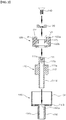
- FIG. 1 is an exploded perspective view of a vortex spray type steam head device according to a first embodiment of the present invention
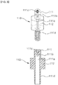
- FIG. 2 is a cross-sectional exploded perspective view of the vortex spray type steam head device according to the first embodiment of the present invention
- FIG. 3 is a view showing a nozzle assembly of the vortex spray type steam head device according to the first embodiment of the present invention
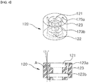
- FIG. 4 is a view showing a rotary body of the vortex spray type steam head device according to the first embodiment of the present invention
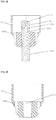
- FIG. 5 is a view showing a cover member of the vortex spray type steam head device according to the first embodiment of the present invention
- FIG. 6 is a cross-sectional view of the vortex spray type steam head device according to the first embodiment of the present invention.
- the vortex spray type steam head device may include a nozzle member 110, a rotary body 120, a support body 130, a fixing bolt 140, a cover member 150, etc.
- the nozzle member 110 which has a cylindrical shape, can receive and spray steam to the outside and may include a steam supply body 111, a protrusive body 112, etc.
- the steam supply body 111 may have a cylindrical shape, a steam supply path 111a longitudinally formed therein, and a plurality of steam spray holes 111b inclined upward to the outer surface from the steam supply path 111a.
- the steam spray holes 111b may be three pieces to efficiently generate a vortex.
- high-pressure steam that is supplied from the steam supply body passes through the steam supply path 111a of the steam supply body 111 and is then primarily sprayed through the steam spray holes 111b. Further, the rotary body 120 is rotated about the steam supply body 111 of the nozzle member 110 by the spray pressure of the steam.
- the steam supply body 111 has a fixing groove 111c formed on the top and the fixing bolt 140 can be inserted and fixed in the fixing groove 111c.
- the steam supply body 111 has a male thread 111d on the outer surface of the lower portion thereof, to it can be thread-fastened to the cover member 150.
- the protrusive body 112 protrudes outward around the outer surface of the middle portion of the steam supply body 111 and may have a pillar shape with a polygonal or circular cross-section.
- the protrusive body 112 may be a reference that divides the steam supply body 111 up and down.
- the rotary body 120 which has a cylindrical shape, may be rotatably coupled to the upper portion of the nozzle member 110, may have receiving groove 121 having a predetermined depth (e.g., 1 ⁇ 5mm) on the top, and may have a through-hole 122 longitudinally formed through the center portion.
- the rotary body 120 has a plurality of rotational spray holes 123 inclined upward to the top from the inner surface to respectively correspond to the positions of the steam spray holes 111b.
- the inclination of the rotational spray hole 123 is the angle A between a line L1 vertically drawn through an outlet 123a of the rotational spray hole 123 and a line L2 connecting the outlet 123a to an inlet 123b of the rotational spray hole 123 and may be 10 ⁇ 12 degrees.
- the inclination of the rotational spray hole 123 is less than 10 degrees, a vortex is not formed and steam is sprayed almost straight, and when the inclination exceeds 12 degrees, steam is spread, so it is preferable that the inclination is 10 ⁇ 12 degrees.
- the rotational spray holes 123 may have the same thickness or may have different thicknesses.
- the rotational spray holes 123 may have the same inclination or may have different inclinations within 10 ⁇ 12 degrees.
- the rotary body 120 is coupled to the upper portion of the steam supply body 111 of the nozzle member 110 and the bottom of the rotary body 120 is seated on the top of the protrusive body 112.
- high-pressure steam that is supplied from the steam supply body passes through the steam supply path 111a of the steam supply body 111 and is then primarily sprayed through the steam spray holes 111b.
- the rotary body 120 is rotated about the steam supply body 111 of the nozzle member 110 by the spray pressure of the steam, and in this process, steam is secondarily sprayed through the rotary spray holes 123 of the rotary body 120. Accordingly, a vortex is formed.
- the support body 130 is inserted in the receiving groove 121 of the rotary body 120 and can support the rotary body 120.
- the inner side of the support body 130 may be inclined inward to correspond to the bolt head of the fixing bolt 140 to be described below such that the fixing bolt 140 can be inserted through the support body 130 with the bolt head caught.
- the fixing bolt 140 can fix the rotary body 120 to the nozzle member 110 with the support body 130 inserted in the receiving groove 121.
- the fixing bolt 140 has a driver groove formed on the top of the bolt head for inserting a driver and has a cylindrical bolt body having a diameter smaller the head, and the bolt body can be inserted and thread-fastened in the fixing groove 111c.
- the cover member 150 has an open top and a receiving space therein having a predetermined depth (e.g. 12 ⁇ 14mm).
- the nozzle member 110, the rotary body 120, the support body 130, and the fixing bolt 140 are received in the cover member 150.
- the cover member 150 may include a protective cover 151, a coupling cover 152, etc.
- the protective cover 151 has a cylindrical shape with an open top and may have a cover hole 151a on the bottom through which the nozzle member 110 is inserted.
- the coupling cover 152 protrudes with a predetermined length (e.g., 10 ⁇ 15mm) downward from the cover hole 151a and is integrated with the protective cover 151, and the lower portion of the nozzle member 110 can be inserted and fixed in the coupling cover 152.
- a predetermined length e.g. 10 ⁇ 15mm
- the coupling cover 152 has a female thread 152a on the inner side to correspond to the male thread 111d of the steam supply body 111, so it can be thread-fastened to the steam supply body 111.
- a gap is defined between the steam supply body 111 of the nozzle body 110 and the rotary body 120.
- some of steam is sprayed to the rear end of the rotary body 120 through the gap, it can be sprayed forward again through the space defined between the outer surface of the rotary body 120 and the protective cover 151 of the cover member 150.
- the steam that is sprayed directly to the front end of the rotary body 120 by rotation of the rotary body 120 and is sprayed to the rear end of the rotary body 120 through the gap is sprayed again forward by the protective cover 151, so the entire spray area is increased. Therefore, it is possible to reduce noise and increase a sanitizing area.
- the protective cover 151 may have at least one drain hole 151b for discharging water on the bottom thereof.
- the drain hole 151b prevents water drops of steam, which is sprayed through the rear end of the rotary body 120 and is partially changed into water due to a temperature difference in the protective cover 151, from collecting on the bottom of the protective cover 151. Accordingly, there is an advantage in that it is possible to prevent problems with the nozzle member 110, the rotary body 120, the support body 130, and the fixing bolt 140 due to contact of water drops.
- FIG. 7 is an exploded perspective view of a vortex spray type steam head device according to a second embodiment of the present invention
- FIG. 8 is a cross-sectional view showing an assembly of a nozzle member and a cover member of the vortex spray type steam head device according to the second embodiment of the present invention
- FIG. 9 is a view showing a cover member of the vortex spray type steam head device according to the second embodiment of the present invention
- FIG. 10 is a view showing the nozzle assembly of the vortex spray type steam head device according to the second embodiment of the present invention.
- the vortex spray type steam head device may include a nozzle member 110', a rotary body 120', a support body 130', a fixing bolt 140', a cover member 150', etc.
- the rotary body 120', the support body 130', and the fixing bolt 140' in this configuration are the same as the rotary body 120, the support body 130, and the fixing bolt 140 of the first embodiment, so they are not described in detail.
- the nozzle member 110' which has a cylindrical shape, can receive and spray steam to the outside and may include a steam supply body 111', etc.
- the steam supply body 111' may have a cylindrical shape, a steam supply path 111'a longitudinally formed therein, and a plurality of steam spray holes 111'b inclined upward to the outside from the steam supply path 111'a.
- the steam spray holes 111'b may be three pieces to efficiently generate a vortex.
- high-pressure steam that is supplied from the steam supplier passes through the steam supply path 111'a of the steam supply body 111' and is then primarily sprayed through the steam spray holes 111'b. Further, the rotary body 120' is rotated about the steam supply body 111' of the nozzle member 110' by the spray pressure of the steam.
- the steam supply body 111' has a fixing groove 111'c formed on the top and the fixing bolt 140' can be inserted and fixed in the fixing groove 111'c.
- the steam supply body 111' has a male thread 111'd on the outer surface of the lower portion thereof, to it can be thread-fastened to the cover member 150'.
- the cover member 150' has an open top and a receiving space therein.
- the nozzle member 110', the rotary body 120', the support body 130', and the fixing bolt 140' are received in the cover member 150'.
- the cover member 150' may include a protective cover 151', etc.
- the protective cover 151' has a cylindrical shape having an open top and a receiving space therein having a predetermined depth (e.g., 12 ⁇ 14mm), and a cover hole 151'a having a predetermined depth (e.g., 10 ⁇ 12mm) may be formed on the bottom of the receiving space such that the lower portion of the nozzle member 110' is inserted therein.
- a predetermined depth e.g. 12 ⁇ 14mm
- a cover hole 151'a having a predetermined depth e.g., 10 ⁇ 12mm
- the cover hole 151'a has a female thread on the inner side to correspond to the male thread 111'd of the steam supply body 111', so it can be thread-fastened to the steam supply body 111'.
- the protective cover 151' may have at least one drain hole 151'b for discharging water on the bottom thereof.
- the drain hole 151'b prevents water drops of steam, which is sprayed through the rear end of the rotary body 120 and is partially changed into water due to a temperature difference in the protective cover 151', from collecting on the bottom of the receiving space of the protective cover 151'. Accordingly, there is an advantage in that it is possible to prevent problems with the nozzle member 110', the rotary body 120', the support body 130', and the fixing bolt 140' due to contact of water drops.
- a gap is defined between the steam supply body 111' of the nozzle body 110' and the rotary body 120'.
- some of steam is sprayed to the rear end of the rotary body 120' through the gap, it can be sprayed forward again through the space defined between the outer surface of the rotary body 120' and the protective cover 151' of the cover member 150'.
- the steam that is sprayed directly to the front end of the rotary body 120' by rotation of the rotary body 120' and is sprayed to the rear end of the rotary body 120' through the gap is sprayed again forward by the protective cover 151', so the entire spray area is increased. Therefore, it is possible to reduce noise and increase a sanitizing area.
- a steam spray may include the spray type steam head devices according to the first embodiment and the second embodiment of the present invention and a grip connected to the spray type steam head devices and formed in a cylindrical shape so that a user can hold it by hand.
- the grip is made of a silicon material, so it is insulated with deforming by high-temperature steam. Accordingly, there is an advantage in that a user can easily hold with a hand and use the steam spray.
- the present invention has an advantage in that it is possible to maintain economical efficiency and constant quality.
- the number of support bodies that are connected to the rotary body is reduced, so thermal expansion of the rotary body and the support body due to high-temperature steam can be reduced. Accordingly, rotation can be efficiently performed. Further, the manufacturing costs are reduced by reducing components.
Landscapes
- Engineering & Computer Science (AREA)
- Food Science & Technology (AREA)
- Apparatus For Disinfection Or Sterilisation (AREA)
- Nozzles (AREA)
Applications Claiming Priority (2)
| Application Number | Priority Date | Filing Date | Title |
|---|---|---|---|
| KR1020190074049A KR102329177B1 (ko) | 2019-06-21 | 2019-06-21 | 와류 분사형 스팀헤드 장치 |
| PCT/KR2019/008579 WO2020256208A1 (ko) | 2019-06-21 | 2019-07-11 | 와류 분사형 스팀헤드 장치 |
Publications (2)
| Publication Number | Publication Date |
|---|---|
| EP3778043A1 true EP3778043A1 (de) | 2021-02-17 |
| EP3778043A4 EP3778043A4 (de) | 2021-12-01 |
Family
ID=74037274
Family Applications (1)
| Application Number | Title | Priority Date | Filing Date |
|---|---|---|---|
| EP19912198.9A Withdrawn EP3778043A4 (de) | 2019-06-21 | 2019-07-11 | Sprühwirbeldampkopf |
Country Status (4)
| Country | Link |
|---|---|
| US (1) | US20220362786A1 (de) |
| EP (1) | EP3778043A4 (de) |
| KR (1) | KR102329177B1 (de) |
| WO (1) | WO2020256208A1 (de) |
Families Citing this family (1)
| Publication number | Priority date | Publication date | Assignee | Title |
|---|---|---|---|---|
| KR102677551B1 (ko) * | 2023-02-02 | 2024-06-21 | 더다인 주식회사 | 건조 및 살균 기능을 가진 싱크대 |
Family Cites Families (9)
| Publication number | Priority date | Publication date | Assignee | Title |
|---|---|---|---|---|
| KR970002396Y1 (ko) * | 1994-11-08 | 1997-03-24 | 윤명복 | 분무각 및 분무거리 조절이 용이한 재배용분무기의 분무노즐 |
| KR970002396U (ko) * | 1995-06-15 | 1997-01-24 | 정석수 | 이동식 소각기 |
| JPH10211450A (ja) * | 1997-01-30 | 1998-08-11 | Matsuoka Shoji Kk | 管内洗浄用の回転ノズルヘッド |
| JP3847164B2 (ja) * | 2001-12-26 | 2006-11-15 | 大浩研熱株式会社 | 回転波動ノズル |
| KR100682606B1 (ko) * | 2005-09-01 | 2007-02-15 | 주식회사 아쿠아닥터 | 고압 스팀을 이용한 소독 장치 및 그 방법 |
| KR101534226B1 (ko) * | 2014-02-19 | 2015-07-06 | 에스제이이 주식회사 | 와류 스팀을 분사하는 스팀청소기 노즐 |
| KR101507712B1 (ko) | 2014-03-05 | 2015-04-07 | 에스제이이 주식회사 | 스팀압력을 이용한 회전 스팀분사 및 오물 흡입이 가능한 스팀청소기용 장치 |
| US20160339458A1 (en) * | 2015-05-19 | 2016-11-24 | Neutek International Inc. | Structure of gyrating nozzle spray gun |
| KR101921668B1 (ko) * | 2017-05-15 | 2018-11-23 | 황병열 | 와류 분사형 스팀헤드 장치 |
-
2019
- 2019-06-21 KR KR1020190074049A patent/KR102329177B1/ko not_active Expired - Fee Related
- 2019-07-11 EP EP19912198.9A patent/EP3778043A4/de not_active Withdrawn
- 2019-07-11 WO PCT/KR2019/008579 patent/WO2020256208A1/ko not_active Ceased
- 2019-07-11 US US16/482,617 patent/US20220362786A1/en not_active Abandoned
Also Published As
| Publication number | Publication date |
|---|---|
| KR20200145272A (ko) | 2020-12-30 |
| US20220362786A1 (en) | 2022-11-17 |
| WO2020256208A1 (ko) | 2020-12-24 |
| EP3778043A4 (de) | 2021-12-01 |
| KR102329177B1 (ko) | 2021-11-18 |
Similar Documents
| Publication | Publication Date | Title |
|---|---|---|
| US7594292B1 (en) | Espresso machine cleaning tool | |
| US8801316B1 (en) | Water jet toothbrush assembly | |
| RU2744845C1 (ru) | Устройство для умывания с устройством подачи воды в виде фонтанной струи | |
| EP3778043A1 (de) | Sprühwirbeldampkopf | |
| US20200154936A1 (en) | Filter holders for espresso machines with damped operating handles | |
| US20040148721A1 (en) | Bottle wash and dry device | |
| KR20180090813A (ko) | 에스프레소 기계를 세척하기 위한 장치 및 방법 | |
| US20110225751A1 (en) | Toilet brush | |
| US9428889B2 (en) | Household faucet spray | |
| US7143780B1 (en) | Faucet hose anti-tangling guard for a shut-off valve | |
| KR20090099249A (ko) | 빗살형 샤워기 헤드 | |
| KR200489063Y1 (ko) | 원스텝 커피 파우더 클린징용 용기 | |
| KR101922693B1 (ko) | 화장품 용기 | |
| CN208910103U (zh) | 用于洗碗机的喷臂和具有其的洗碗机 | |
| US10897986B2 (en) | Brush device that dispenses cleaning fluid | |
| US10286262B1 (en) | Golf equipment washing mechanism for use on conventional golf ball washers | |
| KR20100010289U (ko) | 오뎅 스프레이 건 | |
| US20160095423A1 (en) | Sprayer brush | |
| US11412899B1 (en) | Back and shoulder washing machine | |
| JP3179538U (ja) | 食液用スプレーガン | |
| ATE318534T1 (de) | Filter mit einer befestigungsvorrichtung für eine automatische kaffeemaschine | |
| CA2005437A1 (en) | Toilet brush | |
| KR200276075Y1 (ko) | 이중 노즐이 구성된 샴푸 린스 겸용 용기 | |
| ES2784879T3 (es) | Escobilla de recambio para inodoro con cabezal de escobilla | |
| CN205599408U (zh) | 高压清洗机用喷嘴 |
Legal Events
| Date | Code | Title | Description |
|---|---|---|---|
| STAA | Information on the status of an ep patent application or granted ep patent |
Free format text: STATUS: UNKNOWN |
|
| STAA | Information on the status of an ep patent application or granted ep patent |
Free format text: STATUS: THE INTERNATIONAL PUBLICATION HAS BEEN MADE |
|
| PUAI | Public reference made under article 153(3) epc to a published international application that has entered the european phase |
Free format text: ORIGINAL CODE: 0009012 |
|
| STAA | Information on the status of an ep patent application or granted ep patent |
Free format text: STATUS: REQUEST FOR EXAMINATION WAS MADE |
|
| 17P | Request for examination filed |
Effective date: 20200907 |
|
| AK | Designated contracting states |
Kind code of ref document: A1 Designated state(s): AL AT BE BG CH CY CZ DE DK EE ES FI FR GB GR HR HU IE IS IT LI LT LU LV MC MK MT NL NO PL PT RO RS SE SI SK SM TR |
|
| AX | Request for extension of the european patent |
Extension state: BA ME |
|
| A4 | Supplementary search report drawn up and despatched |
Effective date: 20211103 |
|
| RIC1 | Information provided on ipc code assigned before grant |
Ipc: A47J 31/60 20060101ALI20211027BHEP Ipc: B08B 3/02 20060101AFI20211027BHEP |
|
| DAV | Request for validation of the european patent (deleted) | ||
| DAX | Request for extension of the european patent (deleted) | ||
| STAA | Information on the status of an ep patent application or granted ep patent |
Free format text: STATUS: THE APPLICATION IS DEEMED TO BE WITHDRAWN |
|
| 18D | Application deemed to be withdrawn |
Effective date: 20240201 |