EP3778040A1 - Vibrating actuator - Google Patents
Vibrating actuator Download PDFInfo
- Publication number
- EP3778040A1 EP3778040A1 EP19781746.3A EP19781746A EP3778040A1 EP 3778040 A1 EP3778040 A1 EP 3778040A1 EP 19781746 A EP19781746 A EP 19781746A EP 3778040 A1 EP3778040 A1 EP 3778040A1
- Authority
- EP
- European Patent Office
- Prior art keywords
- arm
- damper
- elastic member
- bridge
- support
- Prior art date
- Legal status (The legal status is an assumption and is not a legal conclusion. Google has not performed a legal analysis and makes no representation as to the accuracy of the status listed.)
- Pending
Links
Images


Classifications
-
- H—ELECTRICITY
- H02—GENERATION; CONVERSION OR DISTRIBUTION OF ELECTRIC POWER
- H02K—DYNAMO-ELECTRIC MACHINES
- H02K33/00—Motors with reciprocating, oscillating or vibrating magnet, armature or coil system
- H02K33/02—Motors with reciprocating, oscillating or vibrating magnet, armature or coil system with armatures moved one way by energisation of a single coil system and returned by mechanical force, e.g. by springs
-
- B—PERFORMING OPERATIONS; TRANSPORTING
- B06—GENERATING OR TRANSMITTING MECHANICAL VIBRATIONS IN GENERAL
- B06B—METHODS OR APPARATUS FOR GENERATING OR TRANSMITTING MECHANICAL VIBRATIONS OF INFRASONIC, SONIC, OR ULTRASONIC FREQUENCY, e.g. FOR PERFORMING MECHANICAL WORK IN GENERAL
- B06B1/00—Methods or apparatus for generating mechanical vibrations of infrasonic, sonic, or ultrasonic frequency
- B06B1/02—Methods or apparatus for generating mechanical vibrations of infrasonic, sonic, or ultrasonic frequency making use of electrical energy
- B06B1/04—Methods or apparatus for generating mechanical vibrations of infrasonic, sonic, or ultrasonic frequency making use of electrical energy operating with electromagnetism
- B06B1/045—Methods or apparatus for generating mechanical vibrations of infrasonic, sonic, or ultrasonic frequency making use of electrical energy operating with electromagnetism using vibrating magnet, armature or coil system
-
- B—PERFORMING OPERATIONS; TRANSPORTING
- B06—GENERATING OR TRANSMITTING MECHANICAL VIBRATIONS IN GENERAL
- B06B—METHODS OR APPARATUS FOR GENERATING OR TRANSMITTING MECHANICAL VIBRATIONS OF INFRASONIC, SONIC, OR ULTRASONIC FREQUENCY, e.g. FOR PERFORMING MECHANICAL WORK IN GENERAL
- B06B1/00—Methods or apparatus for generating mechanical vibrations of infrasonic, sonic, or ultrasonic frequency
- B06B1/10—Methods or apparatus for generating mechanical vibrations of infrasonic, sonic, or ultrasonic frequency making use of mechanical energy
- B06B1/12—Methods or apparatus for generating mechanical vibrations of infrasonic, sonic, or ultrasonic frequency making use of mechanical energy operating with systems involving reciprocating masses
- B06B1/14—Methods or apparatus for generating mechanical vibrations of infrasonic, sonic, or ultrasonic frequency making use of mechanical energy operating with systems involving reciprocating masses the masses being elastically coupled
-
- H—ELECTRICITY
- H02—GENERATION; CONVERSION OR DISTRIBUTION OF ELECTRIC POWER
- H02K—DYNAMO-ELECTRIC MACHINES
- H02K33/00—Motors with reciprocating, oscillating or vibrating magnet, armature or coil system
- H02K33/16—Motors with reciprocating, oscillating or vibrating magnet, armature or coil system with polarised armatures moving in alternate directions by reversal or energisation of a single coil system
Landscapes
- Engineering & Computer Science (AREA)
- Power Engineering (AREA)
- Mechanical Engineering (AREA)
- Physics & Mathematics (AREA)
- Electromagnetism (AREA)
- Apparatuses For Generation Of Mechanical Vibrations (AREA)
- Reciprocating, Oscillating Or Vibrating Motors (AREA)
Abstract
Description
- The present disclosure relates to an oscillatory actuator, and more particularly to an oscillatory actuator with a heavy mover.
- Conventionally, as a haptic interface for realizing a virtual reality, a method of obtaining oscillation by rotating an eccentric mass by a rotary motor has been used.
- However, the conventional method utilizing the rotary motor generates oscillation by an inertial force of the eccentric mass, and it had a disadvantage such as the reaction is slow from the beginning of rotation of the eccentric mass to a moment when the oscillation is obtained as the haptic sensation, and the reality is impaired.
- Therefore, it has been studied to use a voice coil actuator as an actuator for obtaining a more realistic haptic sensation.
- In an oscillatory actuator with a mover of a movable magnet type, a plurality of dampers (leaf springs) is used to support the reciprocating mover. Further, in order to increase the oscillation force, a weight may be added to the mover (see, for example, Cited Reference 1).
- Then, large oscillation outputs are obtained at natural resonance frequencies derived from the spring components of the weight and the dampers.
- Patent Document 1: Japanese Patent No.
5537984 - However, assembly and component variations may cause a non-uniform magnetic field inside the oscillatory actuator and may generate the torsional resonance at the dampers, which generates a large oscillation at other than the natural resonance frequency.
- An embodiment of the present invention has been made in view of the above problems, and an objective is to provide an oscillatory actuator capable of suppressing large oscillations at other than the natural resonance frequency, further having small changes in the natural resonance frequencies, and providing sufficient oscillation outputs.
- An oscillatory actuator according to a first aspect of the present invention that solves the problem includes:
- a case in a cylindrical shape;
- an electromagnetic driver provided inside the case;
- a mover oscillated by the electromagnetic driver along an oscillation axis of the case; and
- a first leaf spring and a second leaf spring arranged on one side and the other side of the mover, each of the first leaf spring and the second leaf spring including a support to which the mover is attached, an annular frame attached to an inner surface of the case, and a plurality of arms each having a spiral shape and connecting the support and the annular frame,
- in which an elastic member that bridges adjacent arms of the first leaf spring and the second leaf spring is provided.
- Other features of the embodiment of the present invention will become more apparent from the following embodiments of the invention and the accompanying drawings.
- By providing the elastic member that bridges the adjacent arms of the first leaf spring and the second leaf spring, the torsional resonance of the leaf springs is reduced, and large oscillation at a frequency other than the natural resonance frequencies is not generated. In addition, since the elastic member bridges the arms, changes in the natural resonance frequencies of the first leaf spring and second leaf spring are small, and it is possible to obtain sufficient oscillation outputs.
- Other advantages of the embodiment of the present invention will become more apparent from the following embodiments of the invention and the accompanying drawings.
-
-
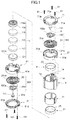
FIG. 1 is an exploded perspective view illustrating an embodiment of the oscillatory actuator according to the present invention. -
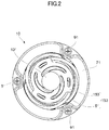
FIG.2 is a top view whenFIG. 1 is assembled. -
FIG. 3 is a front view ofFIG. 2 . -
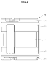
FIG. 4 is a rear view ofFIG. 2 . -
FIG. 5 is a bottom view ofFIG. 2 . -
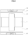
FIG. 6 is a left side view ofFIG. 3 . -
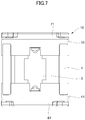
FIG. 7 is a right side view ofFIG. 3 . -
FIG. 8 is a cross-sectional view taken along line VIII-VIII ofFIG. 5 . -
FIG. 9 is a perspective view of a first damper unit including a first damper ofFIG. 1 on which a first elastic member is provided. -
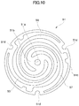
FIG. 10 is a top view of the first damper ofFIG. 9 . -
FIG. 11 is a front view of the first damper unit ofFIG. 9 . -
FIG. 12 is a configuration diagram illustrating a structure of the first elastic member ofFIG. 1 . -
FIG. 13 illustrates an operation of the oscillatory actuator shown inFIG. 1 . -
FIG. 14 illustrates torsional resonance of first elastic damper and second elastic damper shown inFIG. 1 . -
FIG. 15 illustrates resonance of arms of the first elastic damper and second elastic damper shown inFIG. 1 . -
FIG. 16 is a perspective view of the first damper unit including the first damper ofFIG. 1 on which a first elastic member according to another embodiment is provided. -
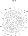
FIG. 17 is a top view of the first damper unit ofFIG. 16 . -
FIG. 18 is a configuration diagram illustrating another structure of the first elastic member ofFIG. 1 . -
FIG. 19 is a configuration diagram illustrating another structure of the first elastic member ofFIG. 1 . -
FIG. 20 is a configuration diagram illustrating another structure of the first elastic member ofFIG. 1 . -
FIG. 21 is a configuration diagram illustrating another structure of the first elastic member ofFIG. 1 . -
FIG. 22 illustrates an example. - Embodiments will be described with reference to the drawings.
FIG. 1 is an exploded perspective view illustrating an embodiment of the oscillatory actuator according to the present invention.FIG.2 is a top view whenFIG. 1 is assembled.FIG. 3 is a front view ofFIG. 2 .FIG. 4 is a rear view ofFIG. 2 .FIG. 5 is a bottom view ofFIG. 2 .FIG. 6 is a left side view ofFIG. 3 .FIG. 7 is a right side view ofFIG. 3 .FIG. 8 is a cross-sectional view taken along line VIII-VIII ofFIG. 5 .FIG. 9 is a perspective view of a damper unit including a first leaf spring ofFIG. 1 on which an elastic member is provided.FIG. 10 is a top view ofFIG. 9 .FIG. 11 is a front view ofFIG. 10 .FIG. 12 is a configuration diagram illustrating a structure of the first elastic member ofFIG. 1 .FIG. 13 illustrates an operation of the oscillatory actuator shown inFIG. 1 .FIG. 14 illustrates torsional resonance of first elastic damper and second elastic damper shown inFIG. 1 .FIG. 15 illustrates resonance of arms of the first elastic damper and second elastic damper shown inFIG. 1 . - An overall configuration of an
oscillatory actuator 10 will be described with reference toFIGS. 1 to 8 . - A
case 1 is in a cylindrical shape with openings at both ends and made of a resin such as ABS. Ayoke 11 in a cylindrical shape and made of a soft magnetic material is located inside thecase 1. Acoil 21 is attached to an inner circumferential surface of theyoke 11 in a state of being electrically insulated from theyoke 11. - A
first cover case 31 in a cylindrical shape and made of a resin such as ABS is located on an end surface at one opening side of thecase 1. Asecond cover case 41 in a cylindrical shape and made of a resin such as ABS is located on an end surface at the other opening side of thecase 1. - A
first damper unit 153 is located on an end surface of thefirst cover case 31 on the opening side opposite to thecase 1. Thefirst damper unit 153 is formed by processing a thin plate of stainless steel (e.g., SUS 304 in this embodiment) and includes afirst damper 51 that is a leaf spring flexible along the oscillation axis O of thecase 1 and a firstelastic member 150 provided on thefirst damper 51. - A
second damper unit 353 is located on the end surface of thesecond cover case 41 on the opening side opposite to thecase 1. Thesecond damper unit 353 is formed by processing a thin plate of stainless steel and includes asecond damper 251 that is a leaf spring flexible along the oscillation axis O of thecase 1 and a secondelastic member 350 provided on thesecond damper 251. - The details of the
first damper unit 153 and second damper unit and 353 will be described later.
Afirst damper cover 71 is located to interpose thefirst damper unit 153 therebetween in cooperation with thefirst cover case 31. Asecond damper cover 81 is located to interpose thesecond damper unit 353 therebetween in cooperation with thesecond cover case 41. - Three through-
holes 71a are formed at a pitch of 120° along the edge of thefirst damper cover 71. Thefirst cover case 31 has three through-holes 31a facing theholes 71a of thefirst damper cover 71. Threescrew holes 1a facing the threeholes 31a of thefirst cover case 31 are formed on the end surface on one opening side of thecase 1. - Then, three
screws 91 are inserted through theholes 71a of thefirst damper cover 71 and theholes 31a of thefirst cover case 31 and screwed into the screw holes 1a of thecase 1. With the circumferential edge of thefirst damper 51 interposed between thefirst damper cover 71 and thefirst cover case 31, thefirst damper cover 71, thefirst damper unit 153, and thefirst cover case 31 are attached to the one opening side of thecase 1 by the threescrews 91. - Three through-
holes 81a are formed at a pitch of 120° along the edge of thesecond damper cover 81. Thesecond cover case 41 has three through-holes 41a facing theholes 81a of thesecond damper cover 81. Three screw holes (not shown) facing the threeholes 41a of thesecond cover case 41 are formed on the end surface on the other opening side of thecase 1. - Then, three
screws 101 are inserted through theholes 81a of thesecond damper cover 81 and theholes 41a of thesecond cover case 41 and screwed into the screw holes formed in the end surface of the other opening side of thecase 1. With the circumferential edge of thesecond damper 251 interposed between thesecond damper cover 81 and thesecond cover case 41, thesecond damper cover 81, thesecond damper unit 353, and thesecond cover case 41 are attached to the other opening side of thecase 1 by the threescrews 101. - A
mover 111, which is surrounded by thecoil 21 and oscillates along the oscillation axis O, is interposed between the first andsecond damper units mover 111 includes amagnet 113 in the shape of a disk, afirst pole piece 115 and asecond pole piece 117 each in the shape of a disk and arranged so as to interpose themagnet 113 therebetween, and a first mass (weights) 119 and a second mass (weights) 121 arranged so as to interpose themagnet 113 and thefirst pole piece 115 and thesecond pole piece 117 therebetween. - The magnetizing direction of the
magnet 113 is the oscillation axis O direction. Thefirst pole piece 115 and thesecond pole piece 117 are made of a soft magnetic material and attached to themagnet 113 by a magnetic attraction force of themagnet 113 and an adhesive, or the like. Thefirst mass 119 and thesecond mass 121 are made of a non-magnetic material and are attached to thefirst pole piece 115 and thesecond pole piece 117 by an adhesive, or the like. Accordingly, themagnet 113, thefirst pole piece 115, thesecond pole piece 117, thefirst mass 119, and thesecond mass 121, which constitute themover 111, are integrated. - A through-
hole 119a and a through-hole 121a penetrating along the central axis are formed on thefirst mass 119 and thesecond mass 121. Further, at the center of thefirst damper 51 and the firstelastic member 150, a through-hole 51a and a through-hole 150a facing thehole 119a of thefirst mass 119 are formed. Similarly, at the center of thesecond damper 251 and the secondelastic member 350 a through-hole 251a and a through-hole 350a facing thehole 121a of thesecond mass 121 are formed. - Then, by inserting a
pin 131 into thehole 51a of thefirst damper 51 and thehole 150a of the firstelastic member 150 and press-fitting the pin into thehole 119a of thefirst mass 119, Inserting apin 141 into thehole 251a of thesecond damper 251 and thehole 350a of the secondelastic member 350 and press-fitting the pin into thehole 121a of thesecond mass 121, themover 111 is oscillatably supported along the oscillation axis O of thecase 1. - A
terminal 3 is formed on the circumferential surface of thecase 1, and to which a lead wire is connected and supplies currents to thecoil 21. (Coil 21) - The
coil 21 will be described with reference toFIGS. 1 to 8 . - The
coil 21 according to this embodiment is located along the oscillation axis O, and includes afirst coil 23 and asecond coil 25. Thefirst coil 23 and thesecond coil 25 are wound along the inner circumferential surface of theyoke 11. - In this manner, inside the
case 1, thefirst coil 23 and thesecond coil 25 provided on thecase 1 side and themagnet 113 provided in themover 111 side constitute an electromagnetic driver of theoscillatory actuator 10. Themover 111 oscillates along the oscillation axis O of thecase 1 due to the electromagnetic action of the electromagnetic driver which will be described later with reference toFIG. 13 . - The
first damper unit 153 andsecond damper unit 353 according to this embodiment will be described in more detail with reference toFIGS. 9 to 11 . Since thefirst damper unit 153 andsecond damper unit 353 are in the same shape and attached to thecase 1 in the same manner, only thefirst damper unit 153 will be described here and the description of thesecond damper unit 353 will be omitted. Then, the same portion of thesecond damper unit 353 as thefirst damper unit 153 are labeled with reference numerals obtained by adding 200 to the reference numerals of the corresponding components of thefirst damper unit 153. For example, when a first arm of thefirst damper 51 of thefirst damper unit 153 is labeled withreference numeral 53, the reference numeral of a first arm of thesecond damper 251 of thesecond damper unit 353 is 253. - At the center of the
first damper 51, which is one of the two components constituting thefirst damper unit 153, asupport 51b attached to themover 111 using thepin 131 that passes through thehole 51a is formed. - An
annular frame 51c of thefirst damper 51 is held between thefirst damper cover 71 and thefirst cover case 31 and attached to thecase 1. Threecutouts 51d are formed on thisannular frame 51c of the first damper 51in order to avoid interference with thescrews 91. - Then, the
support 51b and theannular frame 51c are connected together by three arms such as afirst arm 53, asecond arm 55, and athird arm 57 having the same spiral shape. Thefirst arm 53, thesecond arm 55, and thethird arm 57 are arranged at a pitch of 120° around the oscillation axis O. - The
second damper 251 also has this configuration. - The first
elastic member 150, which is the other component constituting thefirst damper unit 153, has bridges that bridge the adjacent arms of thefirst damper 51. That is, afirst bridge 152 bridges thefirst arm 53 and thethird arms 57 of thefirst damper 51, asecond bridge 155 bridges thesecond arm 55 and thefirst arm 53, and athird bridge 157 bridges thethird arm 57 and thesecond arm 55. Thefirst bridge 152, thesecond bridge 155, and thethird bridge 157 according to this embodiment have ahole 152a, ahole 155, and ahole 157a, respectively. - Accordingly, the
first bridge 152 bridges thefirst arm 53 andthird arm 57 in two positions via thehole 152a. Thesecond bridge 155 bridges thesecond arm 55 andfirst arm 53 in two positions via thehole 155a. Thethird bridge 157 bridges thethird arm 57 andsecond arm 55 in two positions via thehole 157a. - In addition, the first
elastic member 150 has a firststacked arm 159 that is connected to thefirst bridge 152, extends along thefirst arm 53, and is overlapped with thefirst arm 53. This firststacked arm 159 includes a first support-directionstacked arm 159a extending in thesupport 51b direction and a first annular-frame-directionstacked arm 159b extending in the annular-frame 51c direction and connecting to thesecond bridge 155. - Further, the first
elastic member 150 has a secondstacked arm 161 that is connected to thesecond bridge 155, extends along thesecond arm 55, and is overlapped with thesecond arm 55. This secondstacked arm 161 includes a second support-direction stacked arm161a extending in thesupport 51b direction and a second annular-frame-direction stacked arm161b extending in theannular frame 51c direction and connecting to thethird bridge 157. - Furthermore, the first
elastic member 150 has a thirdstacked arm 163 that is connected to thethird bridge 157, extends along thethird arm 57, and is overlapped with thethird arm 57. This thirdstacked arm 163 includes a third support-directionstacked arm 163a extending in thesupport 51b direction and a third annular-frame-directionstacked arm 163b extending in theannular frame 51c direction and connecting to thefirst bridge 152. - Then, the first
elastic member 150 includes astacked support 165 overlapped with thesupport 51b in which the first support-directionstacked arm 159a, the second support direction stackedarm 161a, and the third support-direction stacked arm163a are continuously provided. - The second elastic member350 also has this configuration.
- The first
elastic member 150 and the secondelastic members 350 will be described with reference toFIG. 12 . Since the firstelastic member 150 and the secondelastic member 350 according to this embodiment have the same structure, the description of the secondelastic member 350 will be omitted. - As shown in
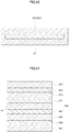
FIG. 12 , the firstelastic member 150 includes, stacking on thefirst damper 51, a firstadhesive layer 171 made of an adhesive, aPE layer 173 made of polyethylene (PE), a secondadhesive layer 175 made of an adhesive, and anelastomer layer 177 made of elastomer which may be, but not limited to, a thermoplastic polyurethane elastomer (TPU). Then, the elastic deformations of the first elastic member 150 (i.e., the shear deformation of thePE layer 173 and the bending deformation of theelastomer layer 177 in this embodiment) control the oscillation of thefirst damper 51. - The second
elastic member 350 also has this structure. - An operation of the
oscillatory actuator 10 according to this embodiment will be described with reference toFIG. 13 . - When the
first coil 23 and thesecond coil 25 are not energized, themover 111 supported by thefirst damper unit 153 and thesecond damper unit 353 is located at the center of thecoil 21. - The
first coil 23 and thesecond coil 25 are alternately energized with alternating currents in directions in which magnetic fields with opposite polarities occurs. That is, the same polarity is generated between adjacent portions of thefirst coil 23 and thesecond coil 25. - At the polarities of
FIG. 13 , a downward thrust (i.e., in the direction of arrow A) is generated on themover 111, when the currents flowing to thefirst coil 23 and thesecond coil 25 are inverted, an upward thrust (i.e., the direction of arrow B) is generated on the mover. - In this way, when alternating currents are applied to the
first coil 23 and thesecond coil 25, themover 111 oscillates along the oscillation axis O while receiving the biasing force by thefirst damper unit 153 andsecond damper unit 353 from both sides. - By the way, the thrust generated in the
mover 111 is basically based on the thrust given based on the Fleming's left-hand rule. In this embodiment, since thefirst coil 23 and thesecond coil 25 are fixed, a thrust as the reaction forces to the forces generated in thefirst coil 23 and the second coil 25in generated in themover 111. - Therefore, it is a horizontal component (i.e., a component orthogonal to the axis direction of the magnet 113) of the magnetic flux of the
magnet 113 of themover 111 that contributes to the thrust. Then, theyoke 11 increases the horizontal component of the magnetic flux of themagnet 113. - According to the above configuration, the following effects can be obtained.
- (1) The first
elastic member 150 has the bridges that bridge the adjacent arms of thefirst damper 51, namely, thefirst bridge 152 that bridges thefirst arm 53 and thethird arms 57, thesecond bridge 155 that bridges thesecond arm 55 and thefirst arm 53, and thethird bridge 157 that bridges thethird arm 57 and thesecond arm 55. - The second
elastic member 350 has the bridges that bridge the adjacent arms of thesecond damper 251, namely, the first bridge 352 that bridges the first arm 253 and the third arm 257, the second bridge 355 that bridges the second arm 255 and the first arm 253, and the third bridge 357 that bridges the third arm 257 and second arm 255. - Therefore, the resonance caused by the torsion of the
first damper 51 andsecond damper 251 is suppressed. In addition, the influences on the amplitude at the natural resonance frequencies can be reduced and a sufficient oscillation output can be obtained.
The resonance caused by the torsion of thefirst damper 51 andsecond damper 251 means ,as shown inFIG. 14 , a resonance in the state that themover 111 is off-axis (tilted) due to assembly and component variations in which the magnetic field inside the actuator becomes non-uniform and the distance between the adjacent arms of thefirst damper 51 and thesecond damper 251 changes. - (2) The first
elastic member 150 has the firststacked arm 159 that is connected to thefirst bridge 152, extends along thefirst arm 53, and is overlapped with thefirst arm 53, the secondstacked arm 161 that is connected to thesecond bridge 155, extends along thesecond arm 55, and is overlapped with thesecond arm 55, and the thirdstacked arm 163 that is connected to thethird bridge 157, extends along thethird arm 57, and is overlapped with thethird arm 57. Each of the stacked arms extends in thesupport 51b direction as well as extending in theannular frame 51c direction and is connected to the other bridges. - The second
elastic member 350 has the first stacked arm 359 that is connected to the first bridge 352, extends along the first arm 253, and is overlapped with the first arm 253, the second stacked arm 361 that is connected to the second bridge 355, extends along the second arm 255, and is overlapped with the second arm 255, and the third stacked arm 363 that is connected to the third bridge 357, extends along the third arm 257, and is overlapped with the third arm 257. Each of the stacked arms extends in the support 251b direction as well as extending in the annular frame 251c direction and is connected to the other bridges. - Therefore, it is possible to suppress the resonance of each arm itself of the
first damper 51 and thesecond damper 251 as shown inFIG. 15 . - The embodiments of the present invention are not limited to the above embodiment. The following modification examples are also possible.
- (1) As the elastic member, those shown in
FIGS. 16 and17 may be used.FIG. 16 is a perspective view of a first damper unit including the first damper ofFIG. 1 on which a first elastic member according to another embodiment is provided.FIG. 17 is a top view of the first damper unit ofFIG. 16 . - A
first damper unit 653 and a second damper unit 853 according to the other embodiment will be described. Since thefirst damper unit 653 and the second damper unit 853 are in the same shape and attaching manner to thecase 1 is also the same, thefirst damper unit 653 will be described here, and the description of the second damper unit 853 will be omitted. Then, the same portion of the second damper unit 853 as thefirst damper unit 653 are labeled with reference numerals obtained by adding 200 to the reference numerals of the corresponding components of thefirst damper unit 653. For example, when a first arm of thefirst damper 551 of thefirst damper unit 653 is labeled withreference numeral 553, the reference numeral of a first arm of a second damper 751 of the second damper unit 853 is 753. - Further, since the first damper 551and the second damper 751 are in the same shapes as the
first damper 51 and thesecond damper 251 described above, the redundant description will be omitted. - A first
elastic member 650, which is the other one of the two components constituting thefirst damper unit 653, has bridges that bridge the adjacent arms of thefirst damper 551. Specifically,first bridges 652 and 652' bridge thefirst arms 553 and thethird arm 557 of thefirst damper 551,second bridges 655 and 655' bridge thesecond arm 555 and thefirst arm 553,third bridges 657 and 657' bridge thethird arm 557 and thesecond arm 555. - Accordingly, t the
first arms 553 and thethird arm 557 are bridged at two locations, namely, thefirst bridge 652 and the first bridge 652'. Thesecond arm 555 and thefirst arm 553 are bridged at two locations, namely, thesecond bridge 655 and the second bridge 655'. Thethird arm 557 and thesecond arm 555 are bridged at two locations, namely, thethird bridge 657 and the third bridge 657'. - Further, the first
elastic member 650 has a first support-directionstacked arm 659 toward a support that is connected to thefirst bridge 652, extends along thefirst arm 553, is overlapped with thefirst arm 553, and extends in asupport 551b direction. The first elastic member has a second support-directionstacked arm 661 that is connected to thesecond bridge 655, extends along thesecond arm 555, is overlapped with thesecond arm 555, and extends in thesupport 551b direction. The first elastic member has a third support-directionstacked arm 663 that is connected to thethird bridge 657, extends along thethird arm 557, is overlapped with thethird arm 557, and extends in thesupport 551b direction. - Then, the first
elastic member 650 includes astacked support 665 overlapped with thesupport 551b of thefirst damper 551 in which the first support-directionstacked arm 659, the second support-directionstacked arm 661, and third support-directionstacked arm 663 are continuously provided. - In addition, in the
first bridge 652, a first intermediatestacked arm 667 overlapped with thethird arm 557 and connected to the third bridge 657'is continuously provided. In thesecond bridge 655, a second intermediatestacked arm 669 overlapped with thefirst arm 553 and connected to the first bridge 652' is continuously provided. In thethird bridge 657, a third intermediatestacked arm 671 overlapped with thesecond arm 555 and connected to the second bridge 655' is continuously provided. - Further, in the third bridge 657', a first annular-frame-direction
stacked arm 673 overlapped with thesecond arm 555 and extends in anannular frame 551c direction is continuously provided. In the first bridge 652', a second annular-frame-direction stacked arm 675overlapped with thethird arm 557 and extends in theannular frame 551c direction is continuously provided. In the second bridge 655', a third annular-frame-direction stacked arm 677overlapped with thefirst arm 553 and extends in theannular frame 551c direction is continuously provided. - The second elastic member 850 also has this configuration.
- (2) The structure of the first elastic member and the second elastic member may be the structure shown in
FIG. 18 . Although the description will be given with the first elastic member, the second elastic member may also have such a structure. -
FIG. 18 is a configuration diagram illustrating another structure of the first elastic member ofFIG. 1 . - As shown in
FIG. 18 , a firstelastic member 750 includes anadhesive layer 771 made of an adhesive and aPE layer 773 made of polyethylene (PE) that are stacked on thefirst damper 51. The elastic deformation of the first elastic member 750 (i.e., the shear deformation of thePE layer 773 in this embodiment) controls the oscillation of thefirst damper 51. - (3) The structure of the first elastic member and the second elastic member may be the structure shown in
FIG. 19 . Although the description will be given with the first elastic member, the second elastic member may also have such a structure. -
FIG. 19 is a configuration diagram illustrating another structure of the first elastic member ofFIG. 1 . - As shown in
FIG. 19 , a firstelastic member 860 includes a firstadhesive layer 871 made of an adhesive and afirst PE layer 873 made of polyethylene (PE) that are stacked on one surface of thefirst damper 51, and a secondadhesive layer 875 made of an adhesive and asecond PE layer 877 made of polyethylene (PE) that are stacked on the other surface of thefirst damper 51. Then, the elastic deformations of the first elastic member 860 (i.e., the shear deformations of the first PE layers 873 andsecond PE layer 877 in this embodiment) control the oscillation of thefirst damper 51. - (4) The structure of the first elastic member and the second elastic member may be the structure shown in
FIG. 20 . Although the description will be given with the first elastic member, the second elastic member may also have such a structure. -
FIG. 20 is a configuration diagram illustrating another structure of the first elastic member ofFIG. 1 . - As shown in
FIG. 20 , the firstelastic member 880 is anelastomer layer 881 formed on thefirst damper 51 by insert molding method. - The, the elastic deformation of the first elastic member 880 (i.e., the bending deformation of the
elastomer layer 881 in this embodiment) controls the oscillation of thefirst damper 51. - (5) The structure of the first elastic member and the second elastic member may be the structure shown in
FIG. 21 . Although the description will be given with the first elastic member, the second elastic member may also have such a structure. -
FIG. 21 is a configuration diagram illustrating another structure of the first elastic member ofFIG. 1 . - As shown in
FIG. 21 , a firstelastic member 950 includes a firstadhesive layer 971 made of an adhesive, afirst PE layer 973 made of polyethylene (PE), a secondadhesive layer 975 made of an adhesive, and afirst elastomer layer 977 made of an elastomer that are stacked on one surface of thefirst damper 51, and a thirdadhesive layer 981 made of an adhesive, asecond PE layer 983 made of polyethylene (PE), a fourthadhesive layer 985 made of an adhesive, and asecond elastomer layer 987 made of an elastomer that are stacked on the other surface of thefirst damper 51.. Then, the elastic deformations of the first elastic member 950 (i.e., the shear deformations of thefirst PE layer 973 and thesecond PE layer 983 and the bending deformations of thefirst elastomer layer 977 andsecond elastomer layer 987 in this embodiment) control the oscillation of thefirst damper 51. - (6) Although the
case 1 has the cylindrical shape, the shape is not limited to the cylinder and may be a square tubular shape, for example, as long as it is a tubular shape. - In order to confirm the effect of the present invention, the applicant examined the relationship, by using an acceleration detector and an FFT analyzer, between the frequency (Frequency [Hz]) and the acceleration (G [Gp-p]) of an oscillatory actuator corresponding to the conventional example using dampers without any elastic member and the
oscillatory actuator 10 shown inFIGS. 1 to 12 using damper units including the elastic members and the dampers.FIG. 22 shows the results. - Note that the unit Gp-p is the value obtained by dividing the acceleration (m/s2) obtained by the FFT analyzer by 9.8 (m/s2) and multiplying by 2√2.
- It is found that without any elastic member as indicated by the broken line, resonance (see the part B) occurs due to the torsion of the first damper and second damper, but that when the first damper unit and second damper unit including the elastic members and the dampers are used as indicated by the solid line, the torsional resonance is suppressed.
- Further, at the natural resonance frequency (see the part A), influence on the amplitude, which is obtained by integrating the acceleration twice, is small, and sufficient oscillation outputs are obtained.
- Next, it is also found that without any elastic member as indicated by the broken line, resonance (see the part C) of the each arm itself of the first damper and second damper occurs, but that when the first damper unit and second damper unit including the elastic members and the dampers are used as indicated by the solid line, the resonance of each arm itself of the first damper and the second damper is suppressed.
-
- 1
- Case
- 11
- Yoke
- 21
- Coil
- 51
- First Damper (First Leaf Spring)
- 53, 253
- First Arm
- 55, 255
- Second Arm
- 57, 257
- Third Arm
- 111
- Mover
- 113
- Magnet
- 150
- First Elastic Member (Elastic Member)
- 251
- Second Damper (Second Leaf Spring)
- 350
- Second Elastic Member (Elastic Member)
Claims (5)
- An oscillatory actuator comprising:a case in a cylindrical shape;an electromagnetic driver provided inside the case;a mover oscillated by the electromagnetic driver along an oscillation axis of the case; anda first leaf spring and a second leaf spring arranged on one side and the other side of the mover, each of the first leaf spring and the second leaf spring including a support to which the mover is attached, an annular frame attached to the case, and a plurality of arms each having a spiral shape and connecting the support and the annular frame,wherein an elastic member that bridges adjacent arms of the first leaf spring and the second leaf spring is provided.
- The oscillatory actuator according to claim 1,
wherein
the elastic member includes:a bridge that bridges the adjacent arms;a support-direction stacked arm continuously provided with the bridge and extending in the support direction along the arm, and being overlapped with the arm; anda stacked support continuously provided with the support-direction stacked arm and being overlapped with the support. - The oscillatory actuator according to claim 2,
wherein
the elastic member includes an annular-frame-direction stacked arm continuously provided with the bridge, extending along the arm in the annular frame direction, and being overlapped with the arm. - The oscillatory actuator according to claim 3,
wherein
the elastic member includes a plurality of bridges, and
the annular-frame-direction stacked arm connects adjacent bridges. - The oscillatory actuator according to any one of claims 1 to 4, wherein
the elastic member contains at least one of an elastomer or polyethylene.
Applications Claiming Priority (2)
| Application Number | Priority Date | Filing Date | Title |
|---|---|---|---|
| JP2018073932A JP7063691B2 (en) | 2018-04-06 | 2018-04-06 | Vibration actuator |
| PCT/JP2019/014805 WO2019194223A1 (en) | 2018-04-06 | 2019-04-03 | Vibrating actuator |
Publications (2)
| Publication Number | Publication Date |
|---|---|
| EP3778040A1 true EP3778040A1 (en) | 2021-02-17 |
| EP3778040A4 EP3778040A4 (en) | 2021-12-22 |
Family
ID=68100315
Family Applications (1)
| Application Number | Title | Priority Date | Filing Date |
|---|---|---|---|
| EP19781746.3A Pending EP3778040A4 (en) | 2018-04-06 | 2019-04-03 | Vibrating actuator |
Country Status (5)
| Country | Link |
|---|---|
| US (2) | US11563365B2 (en) |
| EP (1) | EP3778040A4 (en) |
| JP (1) | JP7063691B2 (en) |
| CN (1) | CN111954578B (en) |
| WO (1) | WO2019194223A1 (en) |
Cited By (1)
| Publication number | Priority date | Publication date | Assignee | Title |
|---|---|---|---|---|
| EP4087101A1 (en) * | 2021-04-30 | 2022-11-09 | INS GmbH | Electrodynamic energy converter |
Families Citing this family (4)
| Publication number | Priority date | Publication date | Assignee | Title |
|---|---|---|---|---|
| WO2020161891A1 (en) * | 2019-02-08 | 2020-08-13 | 三菱電機株式会社 | Electronic apparatus and method for manufacturing electronic apparatus |
| US20210013786A1 (en) * | 2019-07-08 | 2021-01-14 | West Virginia University | High frequency resonant linear machines |
| CN110957885A (en) * | 2019-12-25 | 2020-04-03 | 浙江宝龙机电有限公司 | Linear oscillation motor |
| JP2023183814A (en) * | 2022-06-16 | 2023-12-28 | フォスター電機株式会社 | vibration actuator |
Family Cites Families (84)
| Publication number | Priority date | Publication date | Assignee | Title |
|---|---|---|---|---|
| JPS5283417A (en) | 1975-12-30 | 1977-07-12 | Asahi Glass Co Ltd | Preparation of ester-group-containing fluorocarbon ether derivatives |
| NL175856C (en) * | 1979-12-21 | 1987-12-16 | Terra Dynamics B V | TRANSMITTER FOR RECORDING MECHANICAL VIBRATIONS AND A SEIZE METER CONTAINED WITH SUCH A TRANSMITTER, IN ADDITION TO A SWITCH FOR SUB-GROUPING A NUMBER OF SUCH SEAMOMETERS. |
| JPS6419568A (en) * | 1987-07-14 | 1989-01-23 | Nippon Telegraph & Telephone | Floating head slider supporting device |
| JPH11324914A (en) * | 1998-05-19 | 1999-11-26 | Mitsubishi Electric Corp | Linear compressor |
| JP2000234645A (en) * | 1999-02-16 | 2000-08-29 | Tokai Rubber Ind Ltd | Vibration control exciter for vibration isolation and active vibration control device using this exciter |
| WO2000062945A1 (en) * | 1999-04-16 | 2000-10-26 | Namiki Seimitsu Houseki Kabushiki Kaisha | Vibrating actuator and feeding mechanism thereof |
| US6501357B2 (en) * | 2000-03-16 | 2002-12-31 | Quizix, Inc. | Permanent magnet actuator mechanism |
| JP3591429B2 (en) * | 2000-06-22 | 2004-11-17 | オムロンヘルスケア株式会社 | Flow control valve and sphygmomanometer |
| US6936937B2 (en) * | 2002-06-14 | 2005-08-30 | Sunyen Co., Ltd. | Linear electric generator having an improved magnet and coil structure, and method of manufacture |
| US7078832B2 (en) * | 2002-10-16 | 2006-07-18 | Matsushita Refrigeration Company | Linear motor, and linear compressor using the same |
| JP3950043B2 (en) * | 2002-12-13 | 2007-07-25 | 株式会社シコー技研 | Electromagnetic actuator |
| US20060254270A1 (en) * | 2003-04-10 | 2006-11-16 | Shohzoh Tanaka | Resonance frequency adjusting method and stirling engine |
| KR100541112B1 (en) * | 2004-07-01 | 2006-01-11 | 삼성전기주식회사 | A vertical vibrator of inner weight type |
| JP2006170071A (en) * | 2004-12-15 | 2006-06-29 | Denso Corp | Control device and method for free-piston engine |
| US7449803B2 (en) * | 2005-03-21 | 2008-11-11 | Sahyoun Joseph Y | Electromagnetic motor to create a desired low frequency vibration or to cancel an undesired low frequency vibration |
| US7576454B2 (en) * | 2005-05-23 | 2009-08-18 | Ciiis, Llc | Multiple magnet coil in gap generator |
| US7755227B2 (en) * | 2005-10-19 | 2010-07-13 | Alps Electric Co., Ltd. | Vibration generator |
| JP4883675B2 (en) * | 2006-02-03 | 2012-02-22 | シチズン電子株式会社 | Vibrator |
| JP2007184812A (en) * | 2006-01-10 | 2007-07-19 | Citizen Electronics Co Ltd | Vibrator and method of manufacturing same |
| US7538463B2 (en) * | 2006-01-10 | 2009-05-26 | Citizen Electronics Co., Ltd. | Vibrator |
| GB2438255B (en) * | 2006-02-23 | 2009-10-21 | Citizen Electronics | Vibrator |
| JP2008225690A (en) * | 2007-03-09 | 2008-09-25 | Sony Corp | Vibration body, tactile sense function-equipped input device, and electronic equipment |
| GB2439411B (en) * | 2007-04-27 | 2008-07-23 | Perpetuum Ltd | An electromechanical generator for converting mechanical vibrational energy into electrical energy |
| US8115581B2 (en) * | 2008-04-04 | 2012-02-14 | Correlated Magnetics Research, Llc | Techniques for producing an electrical pulse |
| US20110133577A1 (en) * | 2008-08-18 | 2011-06-09 | In Ho Lee | Horizontal linear vibration device |
| JP2010104864A (en) * | 2008-10-28 | 2010-05-13 | Sanyo Electric Co Ltd | Reciprocating vibration generator |
| KR101018214B1 (en) * | 2009-03-16 | 2011-02-28 | 삼성전기주식회사 | Linear vibration motor |
| KR20100116335A (en) * | 2009-04-22 | 2010-11-01 | 엘지이노텍 주식회사 | Linear vibrator |
| KR101059599B1 (en) * | 2009-07-01 | 2011-08-25 | 삼성전기주식회사 | Linear vibration motor |
| KR101090428B1 (en) * | 2009-07-07 | 2011-12-07 | 삼성전기주식회사 | Linear vibrator |
| WO2011011440A2 (en) * | 2009-07-22 | 2011-01-27 | Vbox, Incorporated | Method of controlling gaseous fluid pump |
| KR101084860B1 (en) * | 2009-07-22 | 2011-11-21 | 삼성전기주식회사 | Horizontal Linear vibrator |
| KR101077374B1 (en) * | 2009-07-22 | 2011-10-26 | 삼성전기주식회사 | Horizontal Linear vibrator |
| GB2469347B (en) * | 2009-08-26 | 2011-10-05 | Perpetuum Ltd | An electromechanical generator for converting mechanical vibrational energy into electrical energy |
| KR101069997B1 (en) * | 2009-09-11 | 2011-10-04 | 삼성전기주식회사 | Linear vibration motor |
| KR101077446B1 (en) * | 2009-09-11 | 2011-10-26 | 삼성전기주식회사 | Horizontal linear vibrator |
| KR101079448B1 (en) * | 2009-09-24 | 2011-11-03 | 삼성전기주식회사 | horizontal linear vibrator |
| KR20110042745A (en) * | 2009-10-20 | 2011-04-27 | 삼성전기주식회사 | Linear vibration generator |
| KR101090426B1 (en) * | 2009-11-02 | 2011-12-07 | 삼성전기주식회사 | Linear Vibrator |
| US9137608B2 (en) * | 2009-12-15 | 2015-09-15 | Nec Corporation | Actuator, piezoelectric actuator, electronic device, and method for attenuating vibration and converting vibration direction |
| KR101113561B1 (en) * | 2010-02-08 | 2012-02-24 | 삼성전기주식회사 | A vertical vibrator |
| JP5537984B2 (en) * | 2010-02-16 | 2014-07-02 | 日本電産セイミツ株式会社 | Reciprocating vibration generator |
| JP5659426B2 (en) * | 2010-02-16 | 2015-01-28 | 日本電産セイミツ株式会社 | Vibration generator |
| JP2011230067A (en) * | 2010-04-28 | 2011-11-17 | Alps Electric Co Ltd | Vibration generating device |
| KR101004879B1 (en) * | 2010-05-25 | 2010-12-28 | 삼성전기주식회사 | Linear vibrator |
| KR101101506B1 (en) * | 2010-06-29 | 2012-01-03 | 삼성전기주식회사 | Horizontal linear vibrator |
| US8736129B2 (en) * | 2010-10-21 | 2014-05-27 | Emerson Electric Co. | End caps for stator segments of segmented stator assemblies |
| US9356499B2 (en) * | 2010-11-30 | 2016-05-31 | Seiko Instruments Inc. | Electromagnetic generator |
| US20120146557A1 (en) * | 2010-12-09 | 2012-06-14 | Korea Advanced Institute Of Science And Technology | Vibration generating module, actuator using the same, handheld device, method for generating vibration and recording medium thereof |
| KR101255914B1 (en) * | 2010-12-31 | 2013-04-23 | 삼성전기주식회사 | Linear Vibration Motor |
| US8736086B2 (en) * | 2011-03-25 | 2014-05-27 | Tai-Her Yang | Reciprocal vibration type power generator equipped with inner columnar and outer annular magnetic members, a power storage device, a rectifying circuit, and a charging circuit |
| KR101803809B1 (en) * | 2011-05-18 | 2017-12-04 | 주식회사 이엠텍 | Linear vibrator |
| BRPI1103447A2 (en) * | 2011-07-19 | 2013-07-09 | Whirlpool Sa | spring bundle for compressor and spring bundled compressor |
| KR101354744B1 (en) * | 2011-08-04 | 2014-01-23 | 삼성전기주식회사 | Linear vibration device |
| KR101354773B1 (en) * | 2011-08-04 | 2014-01-23 | 삼성전기주식회사 | Linear Motor |
| US20130099600A1 (en) * | 2011-10-24 | 2013-04-25 | Lg Innotek Co., Ltd. | Linear vibrator |
| KR101388868B1 (en) * | 2012-09-06 | 2014-04-30 | 삼성전기주식회사 | vibratior |
| JP6036143B2 (en) * | 2012-10-11 | 2016-11-30 | ミツミ電機株式会社 | Power generator |
| KR101969438B1 (en) * | 2012-11-12 | 2019-04-16 | 주식회사 엠플러스 | Linear vibration motor |
| KR102030597B1 (en) * | 2013-03-15 | 2019-11-08 | 주식회사 엠플러스 | Vibrator and electronic apparatus having thereof |
| JP5766748B2 (en) * | 2013-06-05 | 2015-08-19 | Thk株式会社 | Linear actuator |
| WO2015068377A1 (en) * | 2013-11-07 | 2015-05-14 | パナソニックIpマネジメント株式会社 | Power generation device |
| JP6023691B2 (en) * | 2013-11-18 | 2016-11-09 | 日本電産コパル株式会社 | Vibration actuator |
| US9660509B2 (en) * | 2014-01-08 | 2017-05-23 | Mplus Co., Ltd. | Linear vibration actuator |
| US9562525B2 (en) * | 2014-02-10 | 2017-02-07 | Haier Us Appliance Solutions, Inc. | Linear compressor |
| US9815085B2 (en) * | 2014-07-18 | 2017-11-14 | Hysonic. Co., Ltd. | Haptic actuator |
| JP6396129B2 (en) * | 2014-09-05 | 2018-09-26 | 日本電産コパル株式会社 | Manufacturing method of linear vibration motor |
| KR101670131B1 (en) * | 2014-09-23 | 2016-10-28 | 한국과학기술원 | Triboelectric energy harvester including coating electrification layer and manufacturing method thereof |
| US10333430B2 (en) * | 2014-11-25 | 2019-06-25 | Georgia Tech Research Corporation | Robust triboelectric nanogenerator based on rolling electrification |
| JP6356588B2 (en) * | 2014-11-29 | 2018-07-11 | 花王株式会社 | Ultrasonic vibrator holding structure |
| CN205051551U (en) * | 2015-07-31 | 2016-02-24 | 瑞声光电科技(常州)有限公司 | Vibration motor |
| CN204906155U (en) * | 2015-07-31 | 2015-12-23 | 瑞声光电科技(常州)有限公司 | Oscillating motor |
| US10418890B2 (en) * | 2016-05-27 | 2019-09-17 | University Of Southern California | Energy harvester with magnets and self-assembled ferrofluid liquid bearing |
| CN106130303B (en) * | 2016-07-21 | 2019-03-22 | 瑞声科技(新加坡)有限公司 | Linear vibration electric motor |
| CN206602446U (en) * | 2016-10-25 | 2017-10-31 | 瑞声科技(新加坡)有限公司 | Linear vibration electric motor |
| CN207251424U (en) * | 2017-04-14 | 2018-04-17 | 瑞声科技(新加坡)有限公司 | Vibrating motor |
| CN206834962U (en) * | 2017-04-14 | 2018-01-02 | 瑞声科技(新加坡)有限公司 | Linear vibration electric motor |
| CN206834955U (en) * | 2017-04-14 | 2018-01-02 | 瑞声科技(新加坡)有限公司 | Vibrating motor |
| CN206834956U (en) * | 2017-04-14 | 2018-01-02 | 瑞声科技(新加坡)有限公司 | Linear vibration electric motor |
| CN206834963U (en) * | 2017-04-14 | 2018-01-02 | 瑞声科技(新加坡)有限公司 | Linear vibration electric motor |
| GB2572350B (en) * | 2018-03-27 | 2023-01-25 | Hitachi Rail Ltd | An electromechanical generator for converting mechanical vibrational energy into electrical energy |
| CN114337177A (en) * | 2018-08-28 | 2022-04-12 | 美蓓亚三美株式会社 | Vibration actuator and electronic device |
| JP7186563B2 (en) | 2018-09-21 | 2022-12-09 | フォスター電機株式会社 | vibration actuator |
| JP7313159B2 (en) | 2019-02-27 | 2023-07-24 | フォスター電機株式会社 | vibration actuator |
-
2018
- 2018-04-06 JP JP2018073932A patent/JP7063691B2/en active Active
-
2019
- 2019-04-03 CN CN201980023749.9A patent/CN111954578B/en active Active
- 2019-04-03 US US17/045,491 patent/US11563365B2/en active Active
- 2019-04-03 WO PCT/JP2019/014805 patent/WO2019194223A1/en active Application Filing
- 2019-04-03 EP EP19781746.3A patent/EP3778040A4/en active Pending
-
2022
- 2022-12-05 US US18/075,343 patent/US11831214B2/en active Active
Cited By (1)
| Publication number | Priority date | Publication date | Assignee | Title |
|---|---|---|---|---|
| EP4087101A1 (en) * | 2021-04-30 | 2022-11-09 | INS GmbH | Electrodynamic energy converter |
Also Published As
| Publication number | Publication date |
|---|---|
| CN111954578A (en) | 2020-11-17 |
| CN111954578B (en) | 2021-12-31 |
| JP7063691B2 (en) | 2022-05-09 |
| US20230103219A1 (en) | 2023-03-30 |
| US11563365B2 (en) | 2023-01-24 |
| US20210159768A1 (en) | 2021-05-27 |
| EP3778040A4 (en) | 2021-12-22 |
| US11831214B2 (en) | 2023-11-28 |
| WO2019194223A1 (en) | 2019-10-10 |
| JP2019181353A (en) | 2019-10-24 |
Similar Documents
| Publication | Publication Date | Title |
|---|---|---|
| EP3778040A1 (en) | Vibrating actuator | |
| JP6750825B2 (en) | Vibration actuator and electronic equipment | |
| JP2019181353A5 (en) | ||
| EP3547510A1 (en) | Vibration actuator and electronic equipment | |
| JP5802547B2 (en) | Electromechanical transducer, electroacoustic transducer and hearing aid using the same | |
| JP6891326B2 (en) | Vibration actuator | |
| EP3859955A1 (en) | Vibration actuator | |
| US11192141B2 (en) | Vibrating actuator | |
| US11031856B2 (en) | Vibration actuator | |
| CN211830531U (en) | Linear vibration motor and electronic apparatus | |
| JP6900565B2 (en) | Vibration actuator | |
| KR20170040482A (en) | Linear Vibrator and Manufacturing Method Therefor | |
| JP7101604B2 (en) | Vibration actuator | |
| CN110799273B (en) | Actuator | |
| JP2020199506A (en) | Vibration actuator | |
| JP2020199505A (en) | Vibration actuator |
Legal Events
| Date | Code | Title | Description |
|---|---|---|---|
| STAA | Information on the status of an ep patent application or granted ep patent |
Free format text: STATUS: THE INTERNATIONAL PUBLICATION HAS BEEN MADE |
|
| PUAI | Public reference made under article 153(3) epc to a published international application that has entered the european phase |
Free format text: ORIGINAL CODE: 0009012 |
|
| STAA | Information on the status of an ep patent application or granted ep patent |
Free format text: STATUS: REQUEST FOR EXAMINATION WAS MADE |
|
| 17P | Request for examination filed |
Effective date: 20201006 |
|
| AK | Designated contracting states |
Kind code of ref document: A1 Designated state(s): AL AT BE BG CH CY CZ DE DK EE ES FI FR GB GR HR HU IE IS IT LI LT LU LV MC MK MT NL NO PL PT RO RS SE SI SK SM TR |
|
| AX | Request for extension of the european patent |
Extension state: BA ME |
|
| DAV | Request for validation of the european patent (deleted) | ||
| DAX | Request for extension of the european patent (deleted) | ||
| A4 | Supplementary search report drawn up and despatched |
Effective date: 20211118 |
|
| RIC1 | Information provided on ipc code assigned before grant |
Ipc: H02K 33/16 20060101ALI20211112BHEP Ipc: B06B 1/04 20060101ALI20211112BHEP Ipc: B06B 1/14 20060101AFI20211112BHEP |
|
| STAA | Information on the status of an ep patent application or granted ep patent |
Free format text: STATUS: EXAMINATION IS IN PROGRESS |
|
| 17Q | First examination report despatched |
Effective date: 20230426 |