EP3777995A1 - Ceramic honeycomb filter - Google Patents
Ceramic honeycomb filter Download PDFInfo
- Publication number
- EP3777995A1 EP3777995A1 EP19774409.7A EP19774409A EP3777995A1 EP 3777995 A1 EP3777995 A1 EP 3777995A1 EP 19774409 A EP19774409 A EP 19774409A EP 3777995 A1 EP3777995 A1 EP 3777995A1
- Authority
- EP
- European Patent Office
- Prior art keywords
- mass
- particles
- ceramic honeycomb
- plugs
- ceramic
- Prior art date
- Legal status (The legal status is an assumption and is not a legal conclusion. Google has not performed a legal analysis and makes no representation as to the accuracy of the status listed.)
- Granted
Links
Images

Classifications
-
- B—PERFORMING OPERATIONS; TRANSPORTING
- B01—PHYSICAL OR CHEMICAL PROCESSES OR APPARATUS IN GENERAL
- B01D—SEPARATION
- B01D39/00—Filtering material for liquid or gaseous fluids
- B01D39/14—Other self-supporting filtering material ; Other filtering material
- B01D39/20—Other self-supporting filtering material ; Other filtering material of inorganic material, e.g. asbestos paper, metallic filtering material of non-woven wires
- B01D39/2068—Other inorganic materials, e.g. ceramics
- B01D39/2072—Other inorganic materials, e.g. ceramics the material being particulate or granular
- B01D39/2075—Other inorganic materials, e.g. ceramics the material being particulate or granular sintered or bonded by inorganic agents
-
- B—PERFORMING OPERATIONS; TRANSPORTING
- B01—PHYSICAL OR CHEMICAL PROCESSES OR APPARATUS IN GENERAL
- B01D—SEPARATION
- B01D46/00—Filters or filtering processes specially modified for separating dispersed particles from gases or vapours
- B01D46/24—Particle separators, e.g. dust precipitators, using rigid hollow filter bodies
- B01D46/2403—Particle separators, e.g. dust precipitators, using rigid hollow filter bodies characterised by the physical shape or structure of the filtering element
- B01D46/2418—Honeycomb filters
-
- B—PERFORMING OPERATIONS; TRANSPORTING
- B01—PHYSICAL OR CHEMICAL PROCESSES OR APPARATUS IN GENERAL
- B01D—SEPARATION
- B01D46/00—Filters or filtering processes specially modified for separating dispersed particles from gases or vapours
- B01D46/24—Particle separators, e.g. dust precipitators, using rigid hollow filter bodies
- B01D46/2403—Particle separators, e.g. dust precipitators, using rigid hollow filter bodies characterised by the physical shape or structure of the filtering element
- B01D46/2418—Honeycomb filters
- B01D46/2425—Honeycomb filters characterized by parameters related to the physical properties of the honeycomb structure material
- B01D46/2429—Honeycomb filters characterized by parameters related to the physical properties of the honeycomb structure material of the honeycomb walls or cells
-
- B—PERFORMING OPERATIONS; TRANSPORTING
- B01—PHYSICAL OR CHEMICAL PROCESSES OR APPARATUS IN GENERAL
- B01D—SEPARATION
- B01D46/00—Filters or filtering processes specially modified for separating dispersed particles from gases or vapours
- B01D46/24—Particle separators, e.g. dust precipitators, using rigid hollow filter bodies
- B01D46/2403—Particle separators, e.g. dust precipitators, using rigid hollow filter bodies characterised by the physical shape or structure of the filtering element
- B01D46/2418—Honeycomb filters
- B01D46/2425—Honeycomb filters characterized by parameters related to the physical properties of the honeycomb structure material
- B01D46/24494—Thermal expansion coefficient, heat capacity or thermal conductivity
-
- C—CHEMISTRY; METALLURGY
- C04—CEMENTS; CONCRETE; ARTIFICIAL STONE; CERAMICS; REFRACTORIES
- C04B—LIME, MAGNESIA; SLAG; CEMENTS; COMPOSITIONS THEREOF, e.g. MORTARS, CONCRETE OR LIKE BUILDING MATERIALS; ARTIFICIAL STONE; CERAMICS; REFRACTORIES; TREATMENT OF NATURAL STONE
- C04B35/00—Shaped ceramic products characterised by their composition; Ceramics compositions; Processing powders of inorganic compounds preparatory to the manufacturing of ceramic products
- C04B35/01—Shaped ceramic products characterised by their composition; Ceramics compositions; Processing powders of inorganic compounds preparatory to the manufacturing of ceramic products based on oxide ceramics
- C04B35/14—Shaped ceramic products characterised by their composition; Ceramics compositions; Processing powders of inorganic compounds preparatory to the manufacturing of ceramic products based on oxide ceramics based on silica
-
- C—CHEMISTRY; METALLURGY
- C04—CEMENTS; CONCRETE; ARTIFICIAL STONE; CERAMICS; REFRACTORIES
- C04B—LIME, MAGNESIA; SLAG; CEMENTS; COMPOSITIONS THEREOF, e.g. MORTARS, CONCRETE OR LIKE BUILDING MATERIALS; ARTIFICIAL STONE; CERAMICS; REFRACTORIES; TREATMENT OF NATURAL STONE
- C04B35/00—Shaped ceramic products characterised by their composition; Ceramics compositions; Processing powders of inorganic compounds preparatory to the manufacturing of ceramic products
- C04B35/01—Shaped ceramic products characterised by their composition; Ceramics compositions; Processing powders of inorganic compounds preparatory to the manufacturing of ceramic products based on oxide ceramics
- C04B35/16—Shaped ceramic products characterised by their composition; Ceramics compositions; Processing powders of inorganic compounds preparatory to the manufacturing of ceramic products based on oxide ceramics based on silicates other than clay
- C04B35/18—Shaped ceramic products characterised by their composition; Ceramics compositions; Processing powders of inorganic compounds preparatory to the manufacturing of ceramic products based on oxide ceramics based on silicates other than clay rich in aluminium oxide
- C04B35/195—Alkaline earth aluminosilicates, e.g. cordierite or anorthite
-
- C—CHEMISTRY; METALLURGY
- C04—CEMENTS; CONCRETE; ARTIFICIAL STONE; CERAMICS; REFRACTORIES
- C04B—LIME, MAGNESIA; SLAG; CEMENTS; COMPOSITIONS THEREOF, e.g. MORTARS, CONCRETE OR LIKE BUILDING MATERIALS; ARTIFICIAL STONE; CERAMICS; REFRACTORIES; TREATMENT OF NATURAL STONE
- C04B35/00—Shaped ceramic products characterised by their composition; Ceramics compositions; Processing powders of inorganic compounds preparatory to the manufacturing of ceramic products
- C04B35/622—Forming processes; Processing powders of inorganic compounds preparatory to the manufacturing of ceramic products
- C04B35/626—Preparing or treating the powders individually or as batches ; preparing or treating macroscopic reinforcing agents for ceramic products, e.g. fibres; mechanical aspects section B
- C04B35/62605—Treating the starting powders individually or as mixtures
- C04B35/62695—Granulation or pelletising
-
- C—CHEMISTRY; METALLURGY
- C04—CEMENTS; CONCRETE; ARTIFICIAL STONE; CERAMICS; REFRACTORIES
- C04B—LIME, MAGNESIA; SLAG; CEMENTS; COMPOSITIONS THEREOF, e.g. MORTARS, CONCRETE OR LIKE BUILDING MATERIALS; ARTIFICIAL STONE; CERAMICS; REFRACTORIES; TREATMENT OF NATURAL STONE
- C04B38/00—Porous mortars, concrete, artificial stone or ceramic ware; Preparation thereof
- C04B38/0006—Honeycomb structures
- C04B38/0012—Honeycomb structures characterised by the material used for sealing or plugging (some of) the channels of the honeycombs
-
- F—MECHANICAL ENGINEERING; LIGHTING; HEATING; WEAPONS; BLASTING
- F01—MACHINES OR ENGINES IN GENERAL; ENGINE PLANTS IN GENERAL; STEAM ENGINES
- F01N—GAS-FLOW SILENCERS OR EXHAUST APPARATUS FOR MACHINES OR ENGINES IN GENERAL; GAS-FLOW SILENCERS OR EXHAUST APPARATUS FOR INTERNAL-COMBUSTION ENGINES
- F01N3/00—Exhaust or silencing apparatus having means for purifying, rendering innocuous, or otherwise treating exhaust
- F01N3/02—Exhaust or silencing apparatus having means for purifying, rendering innocuous, or otherwise treating exhaust for cooling, or for removing solid constituents of, exhaust
- F01N3/021—Exhaust or silencing apparatus having means for purifying, rendering innocuous, or otherwise treating exhaust for cooling, or for removing solid constituents of, exhaust by means of filters
- F01N3/022—Exhaust or silencing apparatus having means for purifying, rendering innocuous, or otherwise treating exhaust for cooling, or for removing solid constituents of, exhaust by means of filters characterised by specially adapted filtering structure, e.g. honeycomb, mesh or fibrous
-
- F—MECHANICAL ENGINEERING; LIGHTING; HEATING; WEAPONS; BLASTING
- F01—MACHINES OR ENGINES IN GENERAL; ENGINE PLANTS IN GENERAL; STEAM ENGINES
- F01N—GAS-FLOW SILENCERS OR EXHAUST APPARATUS FOR MACHINES OR ENGINES IN GENERAL; GAS-FLOW SILENCERS OR EXHAUST APPARATUS FOR INTERNAL-COMBUSTION ENGINES
- F01N3/00—Exhaust or silencing apparatus having means for purifying, rendering innocuous, or otherwise treating exhaust
- F01N3/02—Exhaust or silencing apparatus having means for purifying, rendering innocuous, or otherwise treating exhaust for cooling, or for removing solid constituents of, exhaust
- F01N3/021—Exhaust or silencing apparatus having means for purifying, rendering innocuous, or otherwise treating exhaust for cooling, or for removing solid constituents of, exhaust by means of filters
- F01N3/022—Exhaust or silencing apparatus having means for purifying, rendering innocuous, or otherwise treating exhaust for cooling, or for removing solid constituents of, exhaust by means of filters characterised by specially adapted filtering structure, e.g. honeycomb, mesh or fibrous
- F01N3/0222—Exhaust or silencing apparatus having means for purifying, rendering innocuous, or otherwise treating exhaust for cooling, or for removing solid constituents of, exhaust by means of filters characterised by specially adapted filtering structure, e.g. honeycomb, mesh or fibrous the structure being monolithic, e.g. honeycombs
-
- B—PERFORMING OPERATIONS; TRANSPORTING
- B01—PHYSICAL OR CHEMICAL PROCESSES OR APPARATUS IN GENERAL
- B01D—SEPARATION
- B01D2239/00—Aspects relating to filtering material for liquid or gaseous fluids
- B01D2239/12—Special parameters characterising the filtering material
- B01D2239/1216—Pore size
-
- B—PERFORMING OPERATIONS; TRANSPORTING
- B01—PHYSICAL OR CHEMICAL PROCESSES OR APPARATUS IN GENERAL
- B01D—SEPARATION
- B01D2239/00—Aspects relating to filtering material for liquid or gaseous fluids
- B01D2239/12—Special parameters characterising the filtering material
- B01D2239/1241—Particle diameter
-
- C—CHEMISTRY; METALLURGY
- C04—CEMENTS; CONCRETE; ARTIFICIAL STONE; CERAMICS; REFRACTORIES
- C04B—LIME, MAGNESIA; SLAG; CEMENTS; COMPOSITIONS THEREOF, e.g. MORTARS, CONCRETE OR LIKE BUILDING MATERIALS; ARTIFICIAL STONE; CERAMICS; REFRACTORIES; TREATMENT OF NATURAL STONE
- C04B2111/00—Mortars, concrete or artificial stone or mixtures to prepare them, characterised by specific function, property or use
- C04B2111/00474—Uses not provided for elsewhere in C04B2111/00
- C04B2111/00793—Uses not provided for elsewhere in C04B2111/00 as filters or diaphragms
-
- C—CHEMISTRY; METALLURGY
- C04—CEMENTS; CONCRETE; ARTIFICIAL STONE; CERAMICS; REFRACTORIES
- C04B—LIME, MAGNESIA; SLAG; CEMENTS; COMPOSITIONS THEREOF, e.g. MORTARS, CONCRETE OR LIKE BUILDING MATERIALS; ARTIFICIAL STONE; CERAMICS; REFRACTORIES; TREATMENT OF NATURAL STONE
- C04B2235/00—Aspects relating to ceramic starting mixtures or sintered ceramic products
- C04B2235/02—Composition of constituents of the starting material or of secondary phases of the final product
- C04B2235/30—Constituents and secondary phases not being of a fibrous nature
- C04B2235/32—Metal oxides, mixed metal oxides, or oxide-forming salts thereof, e.g. carbonates, nitrates, (oxy)hydroxides, chlorides
- C04B2235/3217—Aluminum oxide or oxide forming salts thereof, e.g. bauxite, alpha-alumina
-
- C—CHEMISTRY; METALLURGY
- C04—CEMENTS; CONCRETE; ARTIFICIAL STONE; CERAMICS; REFRACTORIES
- C04B—LIME, MAGNESIA; SLAG; CEMENTS; COMPOSITIONS THEREOF, e.g. MORTARS, CONCRETE OR LIKE BUILDING MATERIALS; ARTIFICIAL STONE; CERAMICS; REFRACTORIES; TREATMENT OF NATURAL STONE
- C04B2235/00—Aspects relating to ceramic starting mixtures or sintered ceramic products
- C04B2235/02—Composition of constituents of the starting material or of secondary phases of the final product
- C04B2235/30—Constituents and secondary phases not being of a fibrous nature
- C04B2235/32—Metal oxides, mixed metal oxides, or oxide-forming salts thereof, e.g. carbonates, nitrates, (oxy)hydroxides, chlorides
- C04B2235/3217—Aluminum oxide or oxide forming salts thereof, e.g. bauxite, alpha-alumina
- C04B2235/3218—Aluminium (oxy)hydroxides, e.g. boehmite, gibbsite, alumina sol
-
- C—CHEMISTRY; METALLURGY
- C04—CEMENTS; CONCRETE; ARTIFICIAL STONE; CERAMICS; REFRACTORIES
- C04B—LIME, MAGNESIA; SLAG; CEMENTS; COMPOSITIONS THEREOF, e.g. MORTARS, CONCRETE OR LIKE BUILDING MATERIALS; ARTIFICIAL STONE; CERAMICS; REFRACTORIES; TREATMENT OF NATURAL STONE
- C04B2235/00—Aspects relating to ceramic starting mixtures or sintered ceramic products
- C04B2235/02—Composition of constituents of the starting material or of secondary phases of the final product
- C04B2235/30—Constituents and secondary phases not being of a fibrous nature
- C04B2235/34—Non-metal oxides, non-metal mixed oxides, or salts thereof that form the non-metal oxides upon heating, e.g. carbonates, nitrates, (oxy)hydroxides, chlorides
- C04B2235/3418—Silicon oxide, silicic acids or oxide forming salts thereof, e.g. silica sol, fused silica, silica fume, cristobalite, quartz or flint
-
- C—CHEMISTRY; METALLURGY
- C04—CEMENTS; CONCRETE; ARTIFICIAL STONE; CERAMICS; REFRACTORIES
- C04B—LIME, MAGNESIA; SLAG; CEMENTS; COMPOSITIONS THEREOF, e.g. MORTARS, CONCRETE OR LIKE BUILDING MATERIALS; ARTIFICIAL STONE; CERAMICS; REFRACTORIES; TREATMENT OF NATURAL STONE
- C04B2235/00—Aspects relating to ceramic starting mixtures or sintered ceramic products
- C04B2235/02—Composition of constituents of the starting material or of secondary phases of the final product
- C04B2235/30—Constituents and secondary phases not being of a fibrous nature
- C04B2235/34—Non-metal oxides, non-metal mixed oxides, or salts thereof that form the non-metal oxides upon heating, e.g. carbonates, nitrates, (oxy)hydroxides, chlorides
- C04B2235/349—Clays, e.g. bentonites, smectites such as montmorillonite, vermiculites or kaolines, e.g. illite, talc or sepiolite
-
- C—CHEMISTRY; METALLURGY
- C04—CEMENTS; CONCRETE; ARTIFICIAL STONE; CERAMICS; REFRACTORIES
- C04B—LIME, MAGNESIA; SLAG; CEMENTS; COMPOSITIONS THEREOF, e.g. MORTARS, CONCRETE OR LIKE BUILDING MATERIALS; ARTIFICIAL STONE; CERAMICS; REFRACTORIES; TREATMENT OF NATURAL STONE
- C04B2235/00—Aspects relating to ceramic starting mixtures or sintered ceramic products
- C04B2235/02—Composition of constituents of the starting material or of secondary phases of the final product
- C04B2235/50—Constituents or additives of the starting mixture chosen for their shape or used because of their shape or their physical appearance
- C04B2235/52—Constituents or additives characterised by their shapes
- C04B2235/528—Spheres
-
- C—CHEMISTRY; METALLURGY
- C04—CEMENTS; CONCRETE; ARTIFICIAL STONE; CERAMICS; REFRACTORIES
- C04B—LIME, MAGNESIA; SLAG; CEMENTS; COMPOSITIONS THEREOF, e.g. MORTARS, CONCRETE OR LIKE BUILDING MATERIALS; ARTIFICIAL STONE; CERAMICS; REFRACTORIES; TREATMENT OF NATURAL STONE
- C04B2235/00—Aspects relating to ceramic starting mixtures or sintered ceramic products
- C04B2235/02—Composition of constituents of the starting material or of secondary phases of the final product
- C04B2235/50—Constituents or additives of the starting mixture chosen for their shape or used because of their shape or their physical appearance
- C04B2235/52—Constituents or additives characterised by their shapes
- C04B2235/5296—Constituents or additives characterised by their shapes with a defined aspect ratio, e.g. indicating sphericity
-
- C—CHEMISTRY; METALLURGY
- C04—CEMENTS; CONCRETE; ARTIFICIAL STONE; CERAMICS; REFRACTORIES
- C04B—LIME, MAGNESIA; SLAG; CEMENTS; COMPOSITIONS THEREOF, e.g. MORTARS, CONCRETE OR LIKE BUILDING MATERIALS; ARTIFICIAL STONE; CERAMICS; REFRACTORIES; TREATMENT OF NATURAL STONE
- C04B2235/00—Aspects relating to ceramic starting mixtures or sintered ceramic products
- C04B2235/02—Composition of constituents of the starting material or of secondary phases of the final product
- C04B2235/50—Constituents or additives of the starting mixture chosen for their shape or used because of their shape or their physical appearance
- C04B2235/54—Particle size related information
- C04B2235/5418—Particle size related information expressed by the size of the particles or aggregates thereof
- C04B2235/5427—Particle size related information expressed by the size of the particles or aggregates thereof millimeter or submillimeter sized, i.e. larger than 0,1 mm
-
- C—CHEMISTRY; METALLURGY
- C04—CEMENTS; CONCRETE; ARTIFICIAL STONE; CERAMICS; REFRACTORIES
- C04B—LIME, MAGNESIA; SLAG; CEMENTS; COMPOSITIONS THEREOF, e.g. MORTARS, CONCRETE OR LIKE BUILDING MATERIALS; ARTIFICIAL STONE; CERAMICS; REFRACTORIES; TREATMENT OF NATURAL STONE
- C04B2235/00—Aspects relating to ceramic starting mixtures or sintered ceramic products
- C04B2235/02—Composition of constituents of the starting material or of secondary phases of the final product
- C04B2235/50—Constituents or additives of the starting mixture chosen for their shape or used because of their shape or their physical appearance
- C04B2235/54—Particle size related information
- C04B2235/5418—Particle size related information expressed by the size of the particles or aggregates thereof
- C04B2235/5436—Particle size related information expressed by the size of the particles or aggregates thereof micrometer sized, i.e. from 1 to 100 micron
-
- C—CHEMISTRY; METALLURGY
- C04—CEMENTS; CONCRETE; ARTIFICIAL STONE; CERAMICS; REFRACTORIES
- C04B—LIME, MAGNESIA; SLAG; CEMENTS; COMPOSITIONS THEREOF, e.g. MORTARS, CONCRETE OR LIKE BUILDING MATERIALS; ARTIFICIAL STONE; CERAMICS; REFRACTORIES; TREATMENT OF NATURAL STONE
- C04B2235/00—Aspects relating to ceramic starting mixtures or sintered ceramic products
- C04B2235/02—Composition of constituents of the starting material or of secondary phases of the final product
- C04B2235/50—Constituents or additives of the starting mixture chosen for their shape or used because of their shape or their physical appearance
- C04B2235/54—Particle size related information
- C04B2235/5463—Particle size distributions
-
- C—CHEMISTRY; METALLURGY
- C04—CEMENTS; CONCRETE; ARTIFICIAL STONE; CERAMICS; REFRACTORIES
- C04B—LIME, MAGNESIA; SLAG; CEMENTS; COMPOSITIONS THEREOF, e.g. MORTARS, CONCRETE OR LIKE BUILDING MATERIALS; ARTIFICIAL STONE; CERAMICS; REFRACTORIES; TREATMENT OF NATURAL STONE
- C04B2235/00—Aspects relating to ceramic starting mixtures or sintered ceramic products
- C04B2235/02—Composition of constituents of the starting material or of secondary phases of the final product
- C04B2235/50—Constituents or additives of the starting mixture chosen for their shape or used because of their shape or their physical appearance
- C04B2235/54—Particle size related information
- C04B2235/5463—Particle size distributions
- C04B2235/5472—Bimodal, multi-modal or multi-fraction
-
- C—CHEMISTRY; METALLURGY
- C04—CEMENTS; CONCRETE; ARTIFICIAL STONE; CERAMICS; REFRACTORIES
- C04B—LIME, MAGNESIA; SLAG; CEMENTS; COMPOSITIONS THEREOF, e.g. MORTARS, CONCRETE OR LIKE BUILDING MATERIALS; ARTIFICIAL STONE; CERAMICS; REFRACTORIES; TREATMENT OF NATURAL STONE
- C04B2235/00—Aspects relating to ceramic starting mixtures or sintered ceramic products
- C04B2235/70—Aspects relating to sintered or melt-casted ceramic products
- C04B2235/72—Products characterised by the absence or the low content of specific components, e.g. alkali metal free alumina ceramics
-
- C—CHEMISTRY; METALLURGY
- C04—CEMENTS; CONCRETE; ARTIFICIAL STONE; CERAMICS; REFRACTORIES
- C04B—LIME, MAGNESIA; SLAG; CEMENTS; COMPOSITIONS THEREOF, e.g. MORTARS, CONCRETE OR LIKE BUILDING MATERIALS; ARTIFICIAL STONE; CERAMICS; REFRACTORIES; TREATMENT OF NATURAL STONE
- C04B2235/00—Aspects relating to ceramic starting mixtures or sintered ceramic products
- C04B2235/70—Aspects relating to sintered or melt-casted ceramic products
- C04B2235/80—Phases present in the sintered or melt-cast ceramic products other than the main phase
-
- C—CHEMISTRY; METALLURGY
- C04—CEMENTS; CONCRETE; ARTIFICIAL STONE; CERAMICS; REFRACTORIES
- C04B—LIME, MAGNESIA; SLAG; CEMENTS; COMPOSITIONS THEREOF, e.g. MORTARS, CONCRETE OR LIKE BUILDING MATERIALS; ARTIFICIAL STONE; CERAMICS; REFRACTORIES; TREATMENT OF NATURAL STONE
- C04B2235/00—Aspects relating to ceramic starting mixtures or sintered ceramic products
- C04B2235/70—Aspects relating to sintered or melt-casted ceramic products
- C04B2235/96—Properties of ceramic products, e.g. mechanical properties such as strength, toughness, wear resistance
- C04B2235/9607—Thermal properties, e.g. thermal expansion coefficient
-
- F—MECHANICAL ENGINEERING; LIGHTING; HEATING; WEAPONS; BLASTING
- F01—MACHINES OR ENGINES IN GENERAL; ENGINE PLANTS IN GENERAL; STEAM ENGINES
- F01N—GAS-FLOW SILENCERS OR EXHAUST APPARATUS FOR MACHINES OR ENGINES IN GENERAL; GAS-FLOW SILENCERS OR EXHAUST APPARATUS FOR INTERNAL-COMBUSTION ENGINES
- F01N2260/00—Exhaust treating devices having provisions not otherwise provided for
- F01N2260/14—Exhaust treating devices having provisions not otherwise provided for for modifying or adapting flow area or back-pressure
-
- F—MECHANICAL ENGINEERING; LIGHTING; HEATING; WEAPONS; BLASTING
- F01—MACHINES OR ENGINES IN GENERAL; ENGINE PLANTS IN GENERAL; STEAM ENGINES
- F01N—GAS-FLOW SILENCERS OR EXHAUST APPARATUS FOR MACHINES OR ENGINES IN GENERAL; GAS-FLOW SILENCERS OR EXHAUST APPARATUS FOR INTERNAL-COMBUSTION ENGINES
- F01N2260/00—Exhaust treating devices having provisions not otherwise provided for
- F01N2260/18—Exhaust treating devices having provisions not otherwise provided for for improving rigidity, e.g. by wings, ribs
-
- F—MECHANICAL ENGINEERING; LIGHTING; HEATING; WEAPONS; BLASTING
- F01—MACHINES OR ENGINES IN GENERAL; ENGINE PLANTS IN GENERAL; STEAM ENGINES
- F01N—GAS-FLOW SILENCERS OR EXHAUST APPARATUS FOR MACHINES OR ENGINES IN GENERAL; GAS-FLOW SILENCERS OR EXHAUST APPARATUS FOR INTERNAL-COMBUSTION ENGINES
- F01N2330/00—Structure of catalyst support or particle filter
- F01N2330/06—Ceramic, e.g. monoliths
-
- F—MECHANICAL ENGINEERING; LIGHTING; HEATING; WEAPONS; BLASTING
- F01—MACHINES OR ENGINES IN GENERAL; ENGINE PLANTS IN GENERAL; STEAM ENGINES
- F01N—GAS-FLOW SILENCERS OR EXHAUST APPARATUS FOR MACHINES OR ENGINES IN GENERAL; GAS-FLOW SILENCERS OR EXHAUST APPARATUS FOR INTERNAL-COMBUSTION ENGINES
- F01N2330/00—Structure of catalyst support or particle filter
- F01N2330/30—Honeycomb supports characterised by their structural details
-
- F—MECHANICAL ENGINEERING; LIGHTING; HEATING; WEAPONS; BLASTING
- F01—MACHINES OR ENGINES IN GENERAL; ENGINE PLANTS IN GENERAL; STEAM ENGINES
- F01N—GAS-FLOW SILENCERS OR EXHAUST APPARATUS FOR MACHINES OR ENGINES IN GENERAL; GAS-FLOW SILENCERS OR EXHAUST APPARATUS FOR INTERNAL-COMBUSTION ENGINES
- F01N2370/00—Selection of materials for exhaust purification
- F01N2370/22—Selection of materials for exhaust purification used in non-catalytic purification apparatus
Definitions
- the present invention relates to a ceramic honeycomb filter having plugs in end portions of predetermined flow paths of a ceramic honeycomb structure.
- a particulate matter-capturing ceramic honeycomb filter (hereinafter simply called “honeycomb filter”) 10 having a structure, which comprises a ceramic honeycomb structure 11 having large numbers of flow paths 15a, 15b partitioned by porous ceramic cell walls 14 for capturing the particulate matter in the exhaust gas by the cell walls 14, is practically used.
- This honeycomb filter 10 has plugs 13a, 13b formed by a plugging material alternately on the exhaust gas inlet-side and outlet-side end surfaces 12a, 12b of the flow paths 15a, 15b surrounded by the cell walls 14.
- an exhaust gas flowing into the flow paths 15b from the inlet-side end surface 12a passes through the cell walls 14 and the flow paths 15a, and exits from the outlet-side end surface 12b. While the exhaust gas passes through the cell walls 14, particulate matter in the exhaust gas is captured by the cell walls 14, so that particulate matter is removed from the exhaust gas.
- the performance required for the honeycomb filter includes low pressure loss, high particulate matter-capturing efficiency, etc. Because the accumulation of the captured particulate matter in the honeycomb filter clogs cell wall pores, resulting in high pressure loss, the accumulated particulate matter should be removed by burning to regenerate the honeycomb filter. Therefore, the honeycomb filter should be able to withstand a use environment in which it is repeatedly exposed to high temperatures when the accumulated particulate matter is burned. Namely, it should have high heat resistance and thermal shock resistance. Accordingly, cordierite has conventionally been used as ceramics forming the cell walls.
- JP 2005-125318 A a ceramic honeycomb filter comprising plugs formed in predetermined flow paths of a sintered ceramic honeycomb made of a material comprising cordierite as a main crystal for removing particulate matter from an exhaust gas passing through porous cell walls partitioning the flow paths, part of the plugs being composed of at least ceramic particles, and an amorphous oxide matrix formed by colloidal oxide, which exists between the ceramic particles.
- This ceramic honeycomb filter is produced by charging a plugging material comprising at least ceramic particles and colloidal oxide into predetermined flow paths of the sintered ceramic honeycomb, and fixing the plugging material to the sintered ceramic honeycomb at a temperature of 1000°C or lower.
- JP 2005-125318 A describes that in Examples, ceramic honeycomb filters having excellent plug strength and thermal shock resistance were obtained by using molten silica or cordierite as ceramic particles.
- WO 2016/052682 A a method for producing a ceramic honeycomb filter comprising a ceramic honeycomb structure having large numbers of flow paths surrounded by porous cell walls made of a material comprising cordierite as a main crystal, and plugs formed in predetermined flow paths of the ceramic honeycomb structure; the plugs being formed by charging a plugging material comprising at least 100 parts by mass of ceramic particles, 5-20 parts by mass on a solid basis of colloidal oxide, and 1.5-4 parts by mass of an organic binder into predetermined flow paths of the ceramic honeycomb structure, and drying the plugging material by microwave or high-frequency induction heating; the ceramic particles having a particle size distribution having at least a first peak and a second peak lower than the first peak; and the first peak being in a particle size range of 100-200 ⁇ m, and the second peak being in a particle size range of 10-30 ⁇ m.
- the method of this invention provides a ceramic honeycomb filter having good bonding strength of the plugs to the cell walls even when the plugs are fixed at low temperatures.
- WO 2016/052682 A describes that in Examples, ceramic honeycomb filters having excellent strength of plugs to cell walls, soot-capturing performance and thermal shock resistance were obtained by using the first and second ceramic particles of cordierite.
- honeycomb filters are required to have higher pressure loss characteristics and capturing ratios of particulate matter having particle sizes of 50 nm or less (so-called nano-particles) in exhaust gases than ever.
- investigation is conducted to improve the cell walls of ceramic honeycomb structures.
- a ceramic honeycomb structure comprising cell walls having a particular pore diameter distribution for effectively capturing nano-sized PM (particulate matter) having large influence on the number of particles in an exhaust gas, even in an initial stage of use before PM is accumulated (starting the use of an unused ceramic honeycomb filter, or the reuse of a regenerated ceramic honeycomb filter).
- ceramic honeycomb filters produced by the methods described in JP 2005-125318 A and WO 2016/052682 A likely have uneven plug length.
- the plug length is the length of a plug in a longitudinal direction of the ceramic honeycomb filter. It is considered that because the plugs are formed by charging a plugging material slurry or paste comprising ceramic particles, colloidal oxide, etc. into end portions of predetermined flow paths, the unevenness of filling length, the shrinkage of the plugging material heated to evaporate a liquid component, etc. occur, resulting in uneven plug length.
- the uneven plug length leads to uneven effective area of cell walls acting as a filter, a longer plug length providing a smaller cell wall area, resulting in increased pressure loss when used for a filter for capturing particulate matter.
- an object of the present invention is to provide a ceramic honeycomb filter capable of effectively capturing nano-sized PM having large influence on the number of particles in an exhaust gas, which is unlikely cracked at cell wall interconnections between plugs even when thermal shock is applied in the regeneration of the filter by burning PM captured by the cell walls, and which has good bonding strength of the plugs to the cell walls and uniform plug length.
- the inventor has conducted intensive investigation on the cause of cracks generated by thermal shock at cell wall interconnections between plugs, in a ceramic honeycomb filter comprising a ceramic honeycomb structure having large numbers of flow paths partitioned by porous cell walls, and plugs formed in end portions of predetermined flow paths of the ceramic honeycomb structure, when the ceramic honeycomb filter is regenerated by burning PM captured by its cell walls.
- the inventor has found that by optimizing a plugging material depending on the thermal expansion coefficient of the cell walls of the ceramic honeycomb structure, this problem can be solved.
- the present invention has been completed based on such finding.
- the ceramic honeycomb filter of the present invention comprises a cordierite-type ceramic honeycomb structure having large numbers of flow paths partitioned by porous cell walls, and plugs formed in end portions of predetermined flow paths of the ceramic honeycomb structure; the cell walls having a thermal expansion coefficient Tw (x 10 -7 /°C) of 10 or less in the flow path direction between 40°C and 800°C; the plugs comprising at least ceramic particles, and 5-25 parts by mass of an amorphous oxide matrix per 100 parts by mass of the ceramic particles; the ceramic particles comprising at least 42-90% by mass of amorphous silica particles, and 10-58% by mass of cordierite particles; and the amorphous silica particles comprising 4-30% by mass of first silica particles having a median particle diameter of 10-40 ⁇ m, and 70-96% by mass of second silica particles having a median particle diameter of 70-200 ⁇ m.
- the amount X (% by mass) of amorphous silica particles in the ceramic particles and the thermal expansion coefficient Tw (x 10 -7 /°C) of the cell walls between 40°C and 800°C preferably meet 118.33 ⁇ 8.1367 ⁇ Tw ⁇ X ⁇ 150.88 ⁇ 8.1367 ⁇ Tw .
- the cordierite particles preferably have a median particle diameter of 5-30 ⁇ m.
- the amorphous silica particles preferably comprise 5-25% by mass of the first silica particles, and 75-95% by mass of the second silica particles.
- the amorphous oxide matrix is preferably silica.
- the present invention can provide a ceramic honeycomb filter unlikely suffering cracking at cell wall interconnections between plugs under thermal shock during the regeneration of the filter, etc., and having good bonding strength of plugs to cell walls and uniform plug length.
- the ceramic honeycomb filter of the present invention comprises a cordierite-type ceramic honeycomb structure having large numbers of flow paths partitioned by porous cell walls, and plugs formed in end portions of predetermined flow paths of the ceramic honeycomb structure; the cell walls having a thermal expansion coefficient Tw (x 10 -7 /°C) of 10 or less in the flow path direction between 40°C and 800°C; the plugs comprising at least ceramic particles, and 5-25 parts by mass of an amorphous oxide matrix per 100 parts by mass of the ceramic particles; the ceramic particles comprising at least 42-90% by mass of amorphous silica particles, and 10-58% by mass of cordierite particles; and the amorphous silica particles comprising 4-30% by mass of first silica particles having a median particle diameter of 10-40 ⁇ m, and 70-96% by mass of second silica particles having a median particle diameter of 70-200 ⁇ m.
- Amorphous silica and cordierite are known as low-thermal expansion materials; amorphous silica having a thermal expansion coefficient of 5 x 10 -7 /°C or less, and cordierite having a thermal expansion coefficient of 16 x 10 -7 /°C or less.
- amorphous silica particles and cordierite particles are used as ceramic particles constituting the plugs, with their mixing ratio and the ratio of the amorphous oxide matrix for binding the ceramic particles optimized. Accordingly, when a filter undergoes thermal shock in burning PM captured by the cell walls for regeneration, cracking unlikely occurs at interconnections of cell walls between the plugs, with high bonding strength between the plugs and the cell walls and uniform plug length.
- the cordierite-type ceramic honeycomb structure constituting the ceramic honeycomb filter of the present invention comprises cordierite as a main crystal, with their cell walls having a thermal expansion coefficient Tw (x 10 -7 /°C) of 10 or less in the flow path direction between 40°C and 800°C.
- Tw thermal expansion coefficient
- the thermal expansion coefficient Tw (x 10 -7 /°C) of the cell walls in the flow path direction between 40°C and 800°C is preferably 9.5 or less, and further preferably 9 or less, and its lower limit is 3 or more, and preferably 3.5 or more.
- the cordierite-type ceramic honeycomb structure constituting the ceramic honeycomb filter of the present invention preferably has porosity of 50-60%, a pore diameter d5, at which a cumulative pore volume is 5% of the total pore volume in a pore diameter distribution measured by mercury porosimetry, being 22 ⁇ m or more and less than 55 ⁇ m, a pore diameter d10 at 10% being 15-35 ⁇ m, a median pore diameter d50 being 10-20 ⁇ m, a pore diameter d85 at 85% being 5-9 ⁇ m, pore diameter d90 at 90% being 3-8 ⁇ m, and a pore diameter d98 at 98% being 2.5 ⁇ m or less.
- the ceramic honeycomb structure can effectively capture nano-sized PM having large influence on the number of particles in an exhaust gas.
- Ceramic particles constituting the plugs in the ceramic honeycomb filter of the present invention comprise at least 42-90% by mass of amorphous silica particles, and 10-58% by mass of cordierite particles. Namely, the amount X of amorphous silica particles in the ceramic particles is 42-90% by mass.
- the plugs When the amount X of amorphous silica particles is less than 42% by mass, the plugs have a large thermal expansion coefficient in the flow path direction because of a small amount of amorphous silica particles in the plugs, resulting in too large thermal expansion coefficient difference between the cell walls and the plugs. As a result, cracking occurs by thermal shock at cell wall interconnections between plugs when the filter is regenerated, etc., resulting in low thermal shock resistance. On the other hand, when the amount X of amorphous silica particles is more than 90% by mass, the plugs have a small thermal expansion coefficient because of a large amount of amorphous silica particles in the plugs, providing too large thermal expansion coefficient difference in the flow path direction between the cell walls and the plugs. As a result, cracking occurs by thermal shock at cell wall interconnections between plugs when the filter is regenerated, etc., resulting in low thermal shock resistance.
- the amount X (% by mass) of amorphous silica particles in the ceramic particles and the thermal expansion coefficient Tw (x 10 -7 /°C) of the cell walls between 40°C and 800°C preferably meet the formula (1) of 118.33 ⁇ 8.1367 ⁇ Tw ⁇ X ⁇ 150.88 ⁇ 8.1367 ⁇ Tw .
- the lower limit of the amount X (% by mass) of amorphous silica particles is preferably (122.4 - 8.1367 x Tw), and further preferably (126.47 - 8.1367 x Tw).
- the upper limit of the amount X (% by mass) is preferably (146.81 - 8.1367 x Tw), and further preferably (142.74 - 8.1367 x Tw).
- the ceramic particles are composed of amorphous silica particles and cordierite particles, 1% or less by mass of ceramic particles (alumina, mullite, etc.) other than amorphous silica particles and cordierite particles may be contained, because 1% or less by mass of other ceramic particles would have small influence on the thermal expansion coefficient of the plugs.
- Amorphous silica particles in the ceramic particles constituting the plugs comprise 4-30% by mass of first silica particles having a median particle diameter of 10-40 ⁇ m, and 70-96% by mass of second silica particles having a median particle diameter of 70-200 ⁇ m.
- first silica particles having a median particle diameter of 10-40 ⁇ m and 70-96% by mass of second silica particles having a median particle diameter of 70-200 ⁇ m.
- the plugging material largely shrinks when heat-dried, likely resulting in uneven plug length.
- the second silica particles are more than 96% by mass (the first silica particles are less than 4 by mass)
- the plugs obtained by heat-drying the plugging material are likely to have low strength.
- the lower limit of the percentage of the second silica particles is preferably 75% by mass, and further preferably 80% by mass (the upper limit of the percentage of the first silica particles is preferably 25% by mass, and further preferably 20% by mass), and the upper limit of the percentage of the second silica particles is preferably 95% by mass, and further preferably 90% by mass (the lower limit of the percentage of the first silica particles is preferably 5% by mass or more, and further preferably 10% by mass or more).
- the plugging material When the first silica particles in the amorphous silica particles have a median particle diameter of less than 10 ⁇ m, the plugging material largely shrinks when heated, likely resulting in uneven plug length. On the other hand, when the median particle diameter is more than 40 ⁇ m, the plugs obtained by heating the plugging material are likely to have low strength.
- the lower limit is 15 ⁇ m or more, and the upper limit is 35 ⁇ m or less.
- the lower limit of the particle diameter D10 at a cumulative volume corresponding to 10% of the total volume is 1 ⁇ m or more, and preferably 5 ⁇ m or more, and the upper limit is 20 ⁇ m or less, and preferably 15 ⁇ m or less.
- the lower limit of the particle diameter D90 at a cumulative volume corresponding to 90% of the total volume is 30 ⁇ m, and preferably 40 ⁇ m, and the upper limit is 70 ⁇ m, and preferably 55 ⁇ m .
- the lower limit is 80 ⁇ m or more, and the upper limit is 180 ⁇ m or less.
- the lower limit of D10 of the second silica particles is 50 ⁇ m or more, and preferably 55 ⁇ m or more, and the upper limit is 80 ⁇ m or less, and preferably 70 ⁇ m or less.
- the lower limit of D90 is 100 ⁇ m or more, and preferably 110 ⁇ m or more, and the upper limit is 300 ⁇ m or less, and preferably 250 ⁇ m or less. Incidentally, D10 ⁇ D50 ⁇ D90.
- the silica particles preferably have sphericity of 0.5 or more.
- the plugging material has high viscosity, exhibiting low fluidity when filled in predetermined flow paths, and thus likely resulting in uneven plug length.
- the sphericity of the silica particles is further preferably 0.6 or more, and more preferably 0.7 or more.
- the sphericity of each silica particle is determined by dividing a projected area of the silica particle by the area of a circle having a diameter corresponding to the maximum length of a line segment connecting two points on a periphery of the silica particle, which passes through the center of gravity of the silica particle, and it can be determined by the image analysis of an electron photomicrograph.
- the silica particles may contain CaO, Na 2 O, K 2 O, Fe 2 O 3 , etc. as impurities.
- the total amount of the above impurities is preferably 0.1% or less.
- the cordierite particles in the ceramic particles constituting the plugs preferably have a median particle diameter of 5-30 ⁇ m.
- the preferred lower and upper limits of the median particle diameter of the cordierite particles are 7 ⁇ m and 25 ⁇ m, respectively.
- the lower limit of D10 of the cordierite particles is preferably 0.5 ⁇ m, and more preferably 1 ⁇ m, and the upper limit is preferably 10 ⁇ m, and more preferably 7 ⁇ m.
- the lower limit of D90 is preferably 15 ⁇ m, and more preferably 20 ⁇ m, and the upper limit is preferably 50 ⁇ m, and more preferably 40 ⁇ m . Incidentally, D10 ⁇ D50 ⁇ D90.
- the cordierite particles may contain Na 2 O, Fe 2 O 3 , K 2 O, CaO, TiO 2 , etc. as impurities in a total amount of 3% or less by mass.
- the amorphous oxide matrix constituting the plugs is preferably formed by colloidal oxide such as colloidal silica, colloidal alumina, etc., because it has excellent bondability to amorphous silica particles and cordierite particles as well as to the cell walls, providing the plugs with high strength. Further, to provide the plugs with a desired thermal expansion coefficient, the colloidal metal oxide is more preferably colloidal silica.
- the amount of the amorphous oxide matrix constituting the plugs in the ceramic honeycomb filter of the present invention is 5-25 parts by mass per 100 parts by mass of the ceramic particles.
- the amount of the amorphous oxide matrix is less than 5 parts by mass per 100 parts by mass of the ceramic particles, the amorphous oxide matrix exhibits an insufficient bonding force to the ceramic particles, failing to provide the plugs with necessary strength.
- the amount of the amorphous oxide matrix is more than 25 parts by mass, the plugs are occupied by too much an amorphous oxide matrix, resulting in a small percentage of ceramic particles as aggregates, providing the plugs with low strength.
- the lower limit of the amount of the amorphous oxide matrix is preferably 10 parts by mass, and the upper limit is preferably 20 parts by mass.
- plugs constituting the ceramic honeycomb filter of the present invention comprise the ceramic particles and the amorphous oxide matrix
- materials forming the plugs are not limited thereto, but organics such as binders, ceramic fibers, cement, unsintered ceramic powder, etc. may be contained if necessary.
- At least cordierite-forming material powder formulated to form cordierite by sintering which has a composition comprising 48-52% by mass of SiO 2 , 33-37% by mass of Al 2 O 3 , and 12-15% by mass of MgO, a pore-forming material, and an organic binder are mixed to prepare a starting material mixture.
- Kaolin, talc, silica, alumina, and aluminum hydroxide can be used for the cordierite-forming material.
- Kaolin and talc are preferably in a planar shape. It is preferable to use kaolin having a cleavage index of 0.80 or more, and talc having a morphology index of 0.5 or more.
- the morphology index of talc can be determined, as described in US
- the moldable material is extruded through a known extrusion die to a honeycomb shape preferably having an outer diameter of 150 mm or more, a wall thickness of 0.05-0.5 mm, and a cell density of 50-500 cells/square inch.
- the extruded ceramic honeycomb green body is dried in a hot-air furnace, a microwave drying apparatus, etc., sintered at the highest keeping temperature of 1380-1420°C, and then machined in the end surfaces by a diamond grinder to obtain a cordierite-type ceramic honeycomb structure 11 having a predetermined length.
- a plugging material is alternately charged into the end surfaces 12a, 12b of predetermined flow paths 15a, 15b of the ceramic honeycomb structure 11, and dried to form plugs 13a, 13b in a checkerboard pattern.
- the charging steps of the plugging material are explained referring to Figs. 2(a) to 2(c) .
- a plug-forming film 21a is first attached to one end surface 12a of the ceramic honeycomb structure 11, and provided with holes 22 in a checkerboard pattern by a laser, etc. at positions corresponding to the flow paths 15a [ Fig. 2(a) ].
- a plug-forming film 21b is attached to another end surface 12b, and provided with holes 22 in a checkerboard pattern by a laser, etc.
- the holes 22 are arranged such that the flow paths 15b open on the end surface 12a and the flow paths 15a open on the end surface 12b are alternately positioned.
- the method of forming the holes 22 is not restricted, as long as the plug-forming film can be provided with openings. For example, a method of pushing a metal rod having a sharp tip end or a heated metal rod to the film may be used.
- the plugging material 23 is prepared as follows. First, amorphous silica particles comprising 4-30% by mass of first silica particles having a median particle diameter of 10-40 ⁇ m and 70-96% by mass of second silica particles having a median particle diameter of 70-200 ⁇ m are prepared in a total amount of 100% by mass.
- the first and second silica particles are preferably spherical particles having sphericity of 0.5 or more.
- the spherical particles are preferably produced by melting silica stone in a high-temperature flame for spheroidization by surface tension.
- ceramic particles comprising 42-90% by mass of the above amorphous silica particles and 10-58% by mass of cordierite particles are dry-mixed with 0.5-5.0 parts by mass of a binder such as methylcellulose, etc., and if necessary, ceramic fibers, cement, unsintered ceramic powder, etc. 5-25 parts by mass on a solid basis of colloidal oxide (colloidal silica, colloidal alumina, etc.) is added to 100 parts by mass of the ceramic particles, and wet-mixed and blended with 20-40 parts by mass of water to obtain the plugging material 23.
- a binder such as methylcellulose, etc.
- the amount X (% by mass) of amorphous silica particles in the ceramic particles and the thermal expansion coefficient Tw (x 10 -7 /°C) of the cell walls of the honeycomb structure between 40°C and 800°C preferably meet the formula (1): 118.33 ⁇ 8.1367 ⁇ Tw ⁇ X ⁇ 150.88 ⁇ 8.1367 ⁇ Tw .
- the cordierite particles are obtained, for example, by molding the cordierite-forming powder formulated to form cordierite by sintering to a block-shaped green body, which is sintered in a furnace whose highest temperature is adjusted in a cordierite-forming temperature range, for example, 1350-1450°C, for about 20 hours, and dry-pulverizing the resultant sintered block by a ball mill, etc.
- the colloidal oxide is a colloidal substance, in which nano-sized particles are dispersed in a dispersion medium such as water, etc.
- the colloidal oxide acts to bind amorphous silica particles and cordierite particles constituting the plugs, and bond the plugs to the cell walls.
- the addition of the colloidal oxide increases the fluidity of the plugging material 23, so that the plugging material 23 charged into the flow paths 15b through holes 22 formed in the plug-forming film 21a attached to the end surface 12a of the ceramic honeycomb structure 11 can easily enter to a predetermined depth as described below.
- colloidal oxide is preferable to further improve the fluidity of the plugging material 23, because the plugging material 23 charged into the flow paths 15b through holes 22 formed in the plug-forming film 21a attached to the end surface 12a of the ceramic honeycomb structure 11 can more easily enter to a predetermined depth as described below.
- colloidal silica it is more preferable to use colloidal silica, because it makes it easy to provide the plugs with a desired thermal expansion coefficient.
- the solid fraction of the colloidal oxide is preferably 20-40% by mass.
- One end surface 12a of the ceramic honeycomb structure 11 is then immersed in the blended plugging material 23 to let the plugging material 23 enter the flow paths 15a to a predetermined depth through the holes 22 of the plug-forming film 21a attached to the end surface 12a [ Fig. 2(b) ].
- the plugging material 23 charged into the flow paths 15b on the side of one end surface 12a is dried to remove water from the plugging material 23 and the dispersion medium from the colloidal oxide, thereby binding ceramic particles and bonding the plugs 13a to the cell walls.
- the plugging material 23 can be dried by a hot-air furnace, microwave heating, high-frequency induction heating, etc. Among them, the high-frequency induction heating is preferable.
- the plugging material 23 is similarly charged into another end surface 12b of the ceramic honeycomb structure 11, so that the plugging material 23 enters the flow paths 15b to a predetermined depth.
- the plugging material 23 charged into another end surface 12b is similarly dried to form plugs 13b, thereby obtaining a ceramic honeycomb filter 10 having flow paths 15a, 15b alternately sealed by the plugs 13a, 13b on one end surface 12a and another end surface 12b [ Fig. 2(c) ].
- the thermal expansion coefficient of the cell walls in the flow path direction and the thermal expansion coefficient of the plugs can meet a proper relation.
- the cell walls of the ceramic honeycomb filter have a thermal expansion coefficient Tw (x 10 -7 /°C) of 10 or less in the flow path direction between 40°C and 800°C.
- the plugs comprise at least ceramic particles, and 5-25 parts by mass of an amorphous oxide matrix per 100 parts by mass of the ceramic particles, the ceramic particles comprising at least 42-90% by mass of amorphous silica particles and 10-58% by mass of cordierite particles, and the amorphous silica particles comprising 4-30% by mass of first silica particles having a median particle diameter of 10-40 ⁇ m and 70-96% by mass of second silica particles having a median particle diameter of 70-200 ⁇ m.
- the moldable material was extruded from an extrusion die, and cut to a green body of 270 mm in diameter and 300 mm in length.
- Plugs were formed in the ceramic honeycomb structure 11 as follows.
- the end surfaces 12a, 12b of the ceramic honeycomb structure 11 were ground, and a resin film 21a having a thickness of 0.09 mm was attached as a plug-forming film to each end surface.
- the film was provided with holes 22 in a checkerboard pattern at positions at which the flow paths were to be plugged, by a laser beam [ Fig. 2(a) ].
- Tables 1-3 show ceramic particles and colloidal oxide, which were plugging materials forming the plugs of the ceramic honeycomb filters of Examples. These plugging materials, an organic binder (methylcellulose) and water were mixed with the formulation shown in Table 4, to prepare the plugging materials of Examples 1-9 by the following procedure.
- the amorphous silica particles shown in Table 1 and the cordierite particles shown in Table 2 were dry-mixed with methylcellulose.
- the colloidal silica shown in Table 3 and ion-exchanged water were added to conduct blending for 30 minutes in a vacuum blending mixer, to prepare plugging material slurries.
- the particle size distribution and median particle diameter of the ceramic particles used were measured by a Microtrack particle size distribution meter (MT3000 available from Nikkiso Co., Ltd.).
- the ceramic honeycomb structure 11 on the side of the end surface 12a was then immersed in the plugging material 23, to let the plugging material 23 enter the flow paths 15a to the depth of 10 mm through the holes 22 formed in the film 21a [ Fig. 2(b) ].
- the end surface 12a, on which the plugging material 23 was charged, was heated by high-frequency induction (output: 7 kW) for 30 seconds to dry the plugging material 23, and the film 21a was then peeled from the end surface 12a.
- the honeycomb structure 11 on the side of another end surface 12b was similarly immersed in the plugging material 23, to let the plugging material 23 enter the flow paths 15b to the depth of 10 mm through the holes 22 formed in the film 21b.
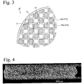
- the scanning electron photomicrograph of a cross section of a plug in the ceramic honeycomb filter of Example 1 is shown in Fig. 4 .
- the plugs comprising amorphous silica particles and cordierite particles bound by an amorphous oxide matrix were fixed to the cell walls in end portions of the flow paths of the ceramic honeycomb structure.
- the moldable material was extruded from an extrusion die, and cut to a green body of 270 mm in diameter and 300 mm in length.
- Plugs were formed in the ceramic honeycomb structure 11 in the same manner as in Example 1 except for using the plugging material of Example 10 shown in Table 4, to produce the ceramic honeycomb filter of Example 10.
- the ceramic honeycomb filters of Comparative Examples 1-3 and 5-10 were produced in the same manner as in Example 1, except for using the plugging materials of Comparative Examples 1-3 and 5-10 shown in Table 4.
- the moldable material was extruded from an extrusion die, and cut to a green body of 270 mm in diameter and 300 mm in length.
- Plugs were formed in the ceramic honeycomb structure 11 in the same manner as in Example 1 to produce the ceramic honeycomb filter of Comparative Example 4.
- the thermal expansion coefficient of the cell walls was determined as an average thermal expansion coefficient between 40°C and 800°C, on a test piece having a cross section shape of 4.5 mm x 4.5 mm x 50 mm (length) cut out of the cell walls with its longitudinal direction substantially in alignment with the flow path direction, by heating it from room temperature to 800°C at a temperature-elevating speed of 10°C/minute and measuring its longitudinal length increase under a constant load of 20 g by a thermomechanical analyzer TMA of a compression load / differential expansion type (ThermoPlus available from Rigaku Corp.).
- the blended plugging material remaining after charged into end portions of the flow paths of the ceramic honeycomb structure was dried and sintered under the same conditions as for the ceramic honeycomb structure, and a test piece having a cross section of 4.5 mm x 4.5 mm x 50 mm (length) was cut out of the resultant sintered body, to measure the thermal expansion coefficient of the plugs by a thermomechanical analyzer in the same manner as for the cell walls.
- the evaluation test of thermal shock resistance was conducted by heating the ceramic honeycomb filter at 500°C for 30 minutes in an electric furnace, rapidly cooling it to room temperature, and then observing both end surfaces with the naked eye to examine whether or not cracks (see Fig. 3 ) were generated at cell wall interconnections between plugs. When cracks were not observed, the same test was conducted with the heating temperature elevated by 25°C (second: 525°C, third: 550°C, ...), and this test was repeated until cracks were generated. The test was conducted on three samples, and the difference between a temperature at which cracks were generated in at least one honeycomb structure and room temperature (heating temperature - room temperature) was regarded as a thermal shock resistance temperature and evaluated by the following standard.
- a pushing rod of stainless steel having a flat tip end surface and a diameter of 0.8 mm was pressed to a plug from the end surface side on which the plug was formed, to measure a load at which the pushing rod broke the plug or detached the plug from the cell walls, and the load was divided by a cross section area (0.50 mm 2 ) of the pushing rod to determine plug strength (MPa), which was averaged for 10 plugs.
- MPa plug strength
- the unevenness of plug length was evaluated by measuring the length of plugs formed in one ceramic honeycomb filter.
- the plug length was determined by inserting a stainless steel rod with a scale into a flow path from an end surface of the ceramic honeycomb structure having no plugs, measuring the length of the flow path when the rod came into contact with a plug on the opposite side (the length of an inserted portion of the stainless steel rod), and calculating its difference from the length of the ceramic honeycomb structure.
- 17 flow paths were measured from each end surface (34 flow paths in total), to calculate the standard deviation of plug length.
- the unevenness of plug length was evaluated by the following standard.
Landscapes
- Chemical & Material Sciences (AREA)
- Engineering & Computer Science (AREA)
- Ceramic Engineering (AREA)
- Inorganic Chemistry (AREA)
- Chemical Kinetics & Catalysis (AREA)
- Physics & Mathematics (AREA)
- Manufacturing & Machinery (AREA)
- Materials Engineering (AREA)
- Structural Engineering (AREA)
- Organic Chemistry (AREA)
- Geometry (AREA)
- Combustion & Propulsion (AREA)
- Mechanical Engineering (AREA)
- General Engineering & Computer Science (AREA)
- Life Sciences & Earth Sciences (AREA)
- Geology (AREA)
- Thermal Sciences (AREA)
- Filtering Materials (AREA)
- Processes For Solid Components From Exhaust (AREA)
- Filtering Of Dispersed Particles In Gases (AREA)
Abstract
Description
- The present invention relates to a ceramic honeycomb filter having plugs in end portions of predetermined flow paths of a ceramic honeycomb structure.
- To remove particulate matter from an exhaust gas discharged from diesel engines, as shown in
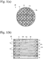
Fig. 1 , a particulate matter-capturing ceramic honeycomb filter (hereinafter simply called "honeycomb filter") 10 having a structure, which comprises aceramic honeycomb structure 11 having large numbers offlow paths ceramic cell walls 14 for capturing the particulate matter in the exhaust gas by thecell walls 14, is practically used. Thishoneycomb filter 10 hasplugs side end surfaces flow paths cell walls 14. Accordingly, an exhaust gas flowing into theflow paths 15b from the inlet-side end surface 12a passes through thecell walls 14 and theflow paths 15a, and exits from the outlet-side end surface 12b. While the exhaust gas passes through thecell walls 14, particulate matter in the exhaust gas is captured by thecell walls 14, so that particulate matter is removed from the exhaust gas. - The performance required for the honeycomb filter includes low pressure loss, high particulate matter-capturing efficiency, etc. Because the accumulation of the captured particulate matter in the honeycomb filter clogs cell wall pores, resulting in high pressure loss, the accumulated particulate matter should be removed by burning to regenerate the honeycomb filter. Therefore, the honeycomb filter should be able to withstand a use environment in which it is repeatedly exposed to high temperatures when the accumulated particulate matter is burned. Namely, it should have high heat resistance and thermal shock resistance. Accordingly, cordierite has conventionally been used as ceramics forming the cell walls.
- The applicant disclosed by
JP 2005-125318 A JP 2005-125318 A - The applicant also disclosed by
WO 2016/052682 A a method for producing a ceramic honeycomb filter comprising a ceramic honeycomb structure having large numbers of flow paths surrounded by porous cell walls made of a material comprising cordierite as a main crystal, and plugs formed in predetermined flow paths of the ceramic honeycomb structure; the plugs being formed by charging a plugging material comprising at least 100 parts by mass of ceramic particles, 5-20 parts by mass on a solid basis of colloidal oxide, and 1.5-4 parts by mass of an organic binder into predetermined flow paths of the ceramic honeycomb structure, and drying the plugging material by microwave or high-frequency induction heating; the ceramic particles having a particle size distribution having at least a first peak and a second peak lower than the first peak; and the first peak being in a particle size range of 100-200 µm, and the second peak being in a particle size range of 10-30 µm. The method of this invention provides a ceramic honeycomb filter having good bonding strength of the plugs to the cell walls even when the plugs are fixed at low temperatures.WO 2016/052682 A describes that in Examples, ceramic honeycomb filters having excellent strength of plugs to cell walls, soot-capturing performance and thermal shock resistance were obtained by using the first and second ceramic particles of cordierite. - To meet recent stricter exhaust gas regulations, investigation is under way to provide an exhaust gas-cleaning apparatus comprising both NOx-removing SCR apparatus and particulate matter-removing honeycomb filter. To this end, the honeycomb filters are required to have higher pressure loss characteristics and capturing ratios of particulate matter having particle sizes of 50 nm or less (so-called nano-particles) in exhaust gases than ever. Thus, investigation is conducted to improve the cell walls of ceramic honeycomb structures. The applicant also discloses in
WO 2016/152709 A a ceramic honeycomb structure comprising cell walls having a particular pore diameter distribution for effectively capturing nano-sized PM (particulate matter) having large influence on the number of particles in an exhaust gas, even in an initial stage of use before PM is accumulated (starting the use of an unused ceramic honeycomb filter, or the reuse of a regenerated ceramic honeycomb filter). - However, when the plugs disclosed in
JP 2005-125318 A WO 2016/052682 A are used in the ceramic honeycomb structure described inWO 2016/152709 A ,cracks 31 are likely generated at cell wall interconnections between plugs of theceramic honeycomb filter 10 when thermal shock is applied during the regeneration of the filter, etc. as shown inFig. 3 , exhibiting insufficient thermal shock resistance. When cracking occurs at cell wall interconnections between plugs, PM, particularly nano-sized PM, is not captured, so that it is discharged from the ceramic honeycomb filter, resulting in a low PM-capturing ratio. This likely fails to meet the regulations of the number of PM particles, which will be enacted in the near future. - Further, ceramic honeycomb filters produced by the methods described in
JP 2005-125318 A WO 2016/052682 A likely have uneven plug length. The plug length is the length of a plug in a longitudinal direction of the ceramic honeycomb filter. It is considered that because the plugs are formed by charging a plugging material slurry or paste comprising ceramic particles, colloidal oxide, etc. into end portions of predetermined flow paths, the unevenness of filling length, the shrinkage of the plugging material heated to evaporate a liquid component, etc. occur, resulting in uneven plug length. The uneven plug length leads to uneven effective area of cell walls acting as a filter, a longer plug length providing a smaller cell wall area, resulting in increased pressure loss when used for a filter for capturing particulate matter. - Accordingly, an object of the present invention is to provide a ceramic honeycomb filter capable of effectively capturing nano-sized PM having large influence on the number of particles in an exhaust gas, which is unlikely cracked at cell wall interconnections between plugs even when thermal shock is applied in the regeneration of the filter by burning PM captured by the cell walls, and which has good bonding strength of the plugs to the cell walls and uniform plug length.
- In view of the above object, the inventor has conducted intensive investigation on the cause of cracks generated by thermal shock at cell wall interconnections between plugs, in a ceramic honeycomb filter comprising a ceramic honeycomb structure having large numbers of flow paths partitioned by porous cell walls, and plugs formed in end portions of predetermined flow paths of the ceramic honeycomb structure, when the ceramic honeycomb filter is regenerated by burning PM captured by its cell walls. As a result, the inventor has found that by optimizing a plugging material depending on the thermal expansion coefficient of the cell walls of the ceramic honeycomb structure, this problem can be solved. The present invention has been completed based on such finding.
- Thus, the ceramic honeycomb filter of the present invention comprises a cordierite-type ceramic honeycomb structure having large numbers of flow paths partitioned by porous cell walls, and plugs formed in end portions of predetermined flow paths of the ceramic honeycomb structure;
the cell walls having a thermal expansion coefficient Tw (x 10-7/°C) of 10 or less in the flow path direction between 40°C and 800°C;
the plugs comprising at least ceramic particles, and 5-25 parts by mass of an amorphous oxide matrix per 100 parts by mass of the ceramic particles;
the ceramic particles comprising at least 42-90% by mass of amorphous silica particles, and 10-58% by mass of cordierite particles; and
the amorphous silica particles comprising 4-30% by mass of first silica particles having a median particle diameter of 10-40 µm, and 70-96% by mass of second silica particles having a median particle diameter of 70-200 µm. - The amount X (% by mass) of amorphous silica particles in the ceramic particles and the thermal expansion coefficient Tw (x 10-7/°C) of the cell walls between 40°C and 800°C preferably meet

- The cordierite particles preferably have a median particle diameter of 5-30 µm.
- The amorphous silica particles preferably comprise 5-25% by mass of the first silica particles, and 75-95% by mass of the second silica particles.
- The amorphous oxide matrix is preferably silica.
- The present invention can provide a ceramic honeycomb filter unlikely suffering cracking at cell wall interconnections between plugs under thermal shock during the regeneration of the filter, etc., and having good bonding strength of plugs to cell walls and uniform plug length.
-
-
Fig. 1(a) is a front view showing an example of the ceramic honeycomb filters of the present invention. -
Fig. 1(b) is a cross-sectional view longitudinally showing an example of the ceramic honeycomb filters of the present invention. -
Fig. 2(a) is a schematic view showing a step of forming plugs of the ceramic honeycomb filter of the present invention. -
Fig. 2(b) is a schematic view showing another step of forming plugs of the ceramic honeycomb filter of the present invention. -
Fig. 2(c) is a schematic view showing a further step of forming plugs of the ceramic honeycomb filter of the present invention. -
Fig. 3 is a front view showing cracks generated in the ceramic honeycomb filter by thermal shock. -
Fig. 4 is a scanning electron photomicrograph showing a cross section of a plug in the ceramic honeycomb filter produced in Example 1. - The embodiments of the present invention will be explained specifically below, without intention of restricting the present invention thereto. Proper modifications, improvements, etc. may be made based on usual knowledge of those skilled in the art, within the scope of the present invention.
- The ceramic honeycomb filter of the present invention comprises a cordierite-type ceramic honeycomb structure having large numbers of flow paths partitioned by porous cell walls, and plugs formed in end portions of predetermined flow paths of the ceramic honeycomb structure; the cell walls having a thermal expansion coefficient Tw (x 10-7/°C) of 10 or less in the flow path direction between 40°C and 800°C; the plugs comprising at least ceramic particles, and 5-25 parts by mass of an amorphous oxide matrix per 100 parts by mass of the ceramic particles; the ceramic particles comprising at least 42-90% by mass of amorphous silica particles, and 10-58% by mass of cordierite particles; and the amorphous silica particles comprising 4-30% by mass of first silica particles having a median particle diameter of 10-40 µm, and 70-96% by mass of second silica particles having a median particle diameter of 70-200 µm.
- Amorphous silica and cordierite are known as low-thermal expansion materials; amorphous silica having a thermal expansion coefficient of 5 x 10⁻⁷/°C or less, and cordierite having a thermal expansion coefficient of 16 x 10-7/°C or less. In the ceramic honeycomb filter of the present invention, amorphous silica particles and cordierite particles are used as ceramic particles constituting the plugs, with their mixing ratio and the ratio of the amorphous oxide matrix for binding the ceramic particles optimized. Accordingly, when a filter undergoes thermal shock in burning PM captured by the cell walls for regeneration, cracking unlikely occurs at interconnections of cell walls between the plugs, with high bonding strength between the plugs and the cell walls and uniform plug length.
- The cordierite-type ceramic honeycomb structure constituting the ceramic honeycomb filter of the present invention comprises cordierite as a main crystal, with their cell walls having a thermal expansion coefficient Tw (x 10-7/°C) of 10 or less in the flow path direction between 40°C and 800°C. When the thermal expansion coefficient Tw (x 10-7/°C) of the cell walls in the flow path direction between 40°C and 800°C is more than 10, the honeycomb structure has low thermal shock resistance, failing to withstand practical use as a ceramic honeycomb filter for removing particulate matter from an exhaust gas discharged from diesel engines. The thermal expansion coefficient Tw (x 10-7/°C) of the cell walls in the flow path direction between 40°C and 800°C is preferably 9.5 or less, and further preferably 9 or less, and its lower limit is 3 or more, and preferably 3.5 or more.
- The cordierite-type ceramic honeycomb structure constituting the ceramic honeycomb filter of the present invention preferably has porosity of 50-60%, a pore diameter d5, at which a cumulative pore volume is 5% of the total pore volume in a pore diameter distribution measured by mercury porosimetry, being 22 µm or more and less than 55 µm, a pore diameter d10 at 10% being 15-35 µm, a median pore diameter d50 being 10-20 µm, a pore diameter d85 at 85% being 5-9 µm, pore diameter d90 at 90% being 3-8 µm, and a pore diameter d98 at 98% being 2.5 µm or less. With such a pore diameter distribution, the ceramic honeycomb structure can effectively capture nano-sized PM having large influence on the number of particles in an exhaust gas.
- Ceramic particles constituting the plugs in the ceramic honeycomb filter of the present invention comprise at least 42-90% by mass of amorphous silica particles, and 10-58% by mass of cordierite particles. Namely, the amount X of amorphous silica particles in the ceramic particles is 42-90% by mass.
- When the amount X of amorphous silica particles is less than 42% by mass, the plugs have a large thermal expansion coefficient in the flow path direction because of a small amount of amorphous silica particles in the plugs, resulting in too large thermal expansion coefficient difference between the cell walls and the plugs. As a result, cracking occurs by thermal shock at cell wall interconnections between plugs when the filter is regenerated, etc., resulting in low thermal shock resistance. On the other hand, when the amount X of amorphous silica particles is more than 90% by mass, the plugs have a small thermal expansion coefficient because of a large amount of amorphous silica particles in the plugs, providing too large thermal expansion coefficient difference in the flow path direction between the cell walls and the plugs. As a result, cracking occurs by thermal shock at cell wall interconnections between plugs when the filter is regenerated, etc., resulting in low thermal shock resistance.
- Further, the amount X (% by mass) of amorphous silica particles in the ceramic particles and the thermal expansion coefficient Tw (x 10-7/°C) of the cell walls between 40°C and 800°C preferably meet the formula (1) of

- With the amount X of amorphous silica particles in a range meeting the formula (1), the difference between the thermal expansion coefficient of the cell walls in the flow path direction and the thermal expansion coefficient of the plugs is small, surely suppressing cracking by thermal shock at cell wall interconnections between plugs when the filter is regenerated, etc. The lower limit of the amount X (% by mass) of amorphous silica particles is preferably (122.4 - 8.1367 x Tw), and further preferably (126.47 - 8.1367 x Tw). The upper limit of the amount X (% by mass) is preferably (146.81 - 8.1367 x Tw), and further preferably (142.74 - 8.1367 x Tw).
- Though the ceramic particles are composed of amorphous silica particles and cordierite particles, 1% or less by mass of ceramic particles (alumina, mullite, etc.) other than amorphous silica particles and cordierite particles may be contained, because 1% or less by mass of other ceramic particles would have small influence on the thermal expansion coefficient of the plugs.
- Amorphous silica particles in the ceramic particles constituting the plugs comprise 4-30% by mass of first silica particles having a median particle diameter of 10-40 µm, and 70-96% by mass of second silica particles having a median particle diameter of 70-200 µm. With at least two types of amorphous silica particles having different median particle diameters contained at the above ratios, the shrinkage of a plugging material is suppressed when heat-dried in the step of forming plugs, resulting in less likelihood of unevenness in plug length, and making stronger the plugs obtained by heat-drying the plugging material.
- When the second silica particles in the amorphous silica particles are less than 70% by mass (the first silica particles are more than 30% by mass), the plugging material largely shrinks when heat-dried, likely resulting in uneven plug length. On the other hand, when the second silica particles are more than 96% by mass (the first silica particles are less than 4 by mass), the plugs obtained by heat-drying the plugging material are likely to have low strength.
- In the amorphous silica particles, the lower limit of the percentage of the second silica particles is preferably 75% by mass, and further preferably 80% by mass (the upper limit of the percentage of the first silica particles is preferably 25% by mass, and further preferably 20% by mass), and the upper limit of the percentage of the second silica particles is preferably 95% by mass, and further preferably 90% by mass (the lower limit of the percentage of the first silica particles is preferably 5% by mass or more, and further preferably 10% by mass or more).
- When the first silica particles in the amorphous silica particles have a median particle diameter of less than 10 µm, the plugging material largely shrinks when heated, likely resulting in uneven plug length. On the other hand, when the median particle diameter is more than 40 µm, the plugs obtained by heating the plugging material are likely to have low strength. Preferably, the lower limit is 15 µm or more, and the upper limit is 35 µm or less. In a curve showing the relation between the particle diameters and cumulative volume of the first silica particles, the lower limit of the particle diameter D10 at a cumulative volume corresponding to 10% of the total volume is 1 µm or more, and preferably 5 µm or more, and the upper limit is 20 µm or less, and preferably 15 µm or less. The lower limit of the particle diameter D90 at a cumulative volume corresponding to 90% of the total volume is 30 µm, and preferably 40 µm, and the upper limit is 70 µm, and preferably 55 µm . Incidentally, D10 < D50 < D90.
- When the median particle diameter of the second silica particles is less than 70 µm, the plugging material largely shrinks when heated, likely resulting in uneven plug length. On the other hand, when the median particle diameter is more than 200 µm, the plugs obtained by heating the plugging material are likely to have low strength. Preferably, the lower limit is 80 µm or more, and the upper limit is 180 µm or less. The lower limit of D10 of the second silica particles is 50 µm or more, and preferably 55 µm or more, and the upper limit is 80 µm or less, and preferably 70 µm or less. The lower limit of D90 is 100 µm or more, and preferably 110 µm or more, and the upper limit is 300 µm or less, and preferably 250 µm or less. Incidentally, D10 < D50 < D90.
- The silica particles preferably have sphericity of 0.5 or more. When the sphericity of the silica particles is less than 0.5, the plugging material has high viscosity, exhibiting low fluidity when filled in predetermined flow paths, and thus likely resulting in uneven plug length. The sphericity of the silica particles is further preferably 0.6 or more, and more preferably 0.7 or more. The sphericity of each silica particle is determined by dividing a projected area of the silica particle by the area of a circle having a diameter corresponding to the maximum length of a line segment connecting two points on a periphery of the silica particle, which passes through the center of gravity of the silica particle, and it can be determined by the image analysis of an electron photomicrograph.
- The silica particles may contain CaO, Na2O, K2O, Fe2O3, etc. as impurities. To prevent the plugs from having too large a thermal expansion coefficient, the total amount of the above impurities is preferably 0.1% or less.
- The cordierite particles in the ceramic particles constituting the plugs preferably have a median particle diameter of 5-30 µm. When the median particle diameter is less than 5 µm, the plugging material largely shrinks when heated, likely resulting in uneven plug length. On the other hand, when the median particle diameter is more than 30 µm, the plugs obtained by heating the plugging material are likely to have low strength. The preferred lower and upper limits of the median particle diameter of the cordierite particles are 7 µm and 25 µm, respectively. The lower limit of D10 of the cordierite particles is preferably 0.5 µm, and more preferably 1 µm, and the upper limit is preferably 10 µm, and more preferably 7 µm. The lower limit of D90 is preferably 15 µm, and more preferably 20 µm, and the upper limit is preferably 50 µm, and more preferably 40 µm . Incidentally, D10 < D50 < D90.
- The cordierite particles may contain Na2O, Fe2O3, K2O, CaO, TiO2, etc. as impurities in a total amount of 3% or less by mass.
- The amorphous oxide matrix constituting the plugs is preferably formed by colloidal oxide such as colloidal silica, colloidal alumina, etc., because it has excellent bondability to amorphous silica particles and cordierite particles as well as to the cell walls, providing the plugs with high strength. Further, to provide the plugs with a desired thermal expansion coefficient, the colloidal metal oxide is more preferably colloidal silica.
- The amount of the amorphous oxide matrix constituting the plugs in the ceramic honeycomb filter of the present invention is 5-25 parts by mass per 100 parts by mass of the ceramic particles. When the amount of the amorphous oxide matrix is less than 5 parts by mass per 100 parts by mass of the ceramic particles, the amorphous oxide matrix exhibits an insufficient bonding force to the ceramic particles, failing to provide the plugs with necessary strength. On the other hand, when the amount of the amorphous oxide matrix is more than 25 parts by mass, the plugs are occupied by too much an amorphous oxide matrix, resulting in a small percentage of ceramic particles as aggregates, providing the plugs with low strength. The lower limit of the amount of the amorphous oxide matrix is preferably 10 parts by mass, and the upper limit is preferably 20 parts by mass.
- Though the plugs constituting the ceramic honeycomb filter of the present invention comprise the ceramic particles and the amorphous oxide matrix, materials forming the plugs are not limited thereto, but organics such as binders, ceramic fibers, cement, unsintered ceramic powder, etc. may be contained if necessary.
- At least cordierite-forming material powder formulated to form cordierite by sintering, which has a composition comprising 48-52% by mass of SiO2, 33-37% by mass of Al2O3, and 12-15% by mass of MgO, a pore-forming material, and an organic binder are mixed to prepare a starting material mixture. Kaolin, talc, silica, alumina, and aluminum hydroxide can be used for the cordierite-forming material. Kaolin and talc are preferably in a planar shape. It is preferable to use kaolin having a cleavage index of 0.80 or more, and talc having a morphology index of 0.5 or more.
- The cleavage index of kaolin particles can be determined, as described in
JP 2006-265034 A 
- The morphology index of talc can be determined, as described in US
- Patent
5,141,686 , by measuring the X-ray diffraction of planar talc particles, and calculating the following formula:
- Water, a lubricant, etc. are added to the starting material mixture, and kneaded to prepare a moldable material. The moldable material is extruded through a known extrusion die to a honeycomb shape preferably having an outer diameter of 150 mm or more, a wall thickness of 0.05-0.5 mm, and a cell density of 50-500 cells/square inch. The extruded ceramic honeycomb green body is dried in a hot-air furnace, a microwave drying apparatus, etc., sintered at the highest keeping temperature of 1380-1420°C, and then machined in the end surfaces by a diamond grinder to obtain a cordierite-type
ceramic honeycomb structure 11 having a predetermined length. By sintering a green body obtained by extruding the cordierite-forming material powder using planar kaolin and talc to a honeycomb shape at a temperature of 1380-1420°C, it is possible to produce a ceramic honeycomb structure having cell walls whose thermal expansion coefficient Tw (x 10-7/°C) in the flow path direction is 10 or less between 40°C and 800°C. - A plugging material is alternately charged into the end surfaces 12a, 12b of
predetermined flow paths ceramic honeycomb structure 11, and dried to formplugs Figs. 2(a) to 2(c) . A plug-formingfilm 21a is first attached to oneend surface 12a of theceramic honeycomb structure 11, and provided withholes 22 in a checkerboard pattern by a laser, etc. at positions corresponding to theflow paths 15a [Fig. 2(a) ]. Likewise, a plug-formingfilm 21b is attached to anotherend surface 12b, and provided withholes 22 in a checkerboard pattern by a laser, etc. at positions corresponding to theflow paths 15b [Fig. 2(a) ]. Theholes 22 are arranged such that theflow paths 15b open on theend surface 12a and theflow paths 15a open on theend surface 12b are alternately positioned. The method of forming theholes 22 is not restricted, as long as the plug-forming film can be provided with openings. For example, a method of pushing a metal rod having a sharp tip end or a heated metal rod to the film may be used. - The plugging
material 23 is prepared as follows. First, amorphous silica particles comprising 4-30% by mass of first silica particles having a median particle diameter of 10-40 µm and 70-96% by mass of second silica particles having a median particle diameter of 70-200 µm are prepared in a total amount of 100% by mass. The first and second silica particles are preferably spherical particles having sphericity of 0.5 or more. The spherical particles are preferably produced by melting silica stone in a high-temperature flame for spheroidization by surface tension. Next, 100 parts by mass of ceramic particles comprising 42-90% by mass of the above amorphous silica particles and 10-58% by mass of cordierite particles are dry-mixed with 0.5-5.0 parts by mass of a binder such as methylcellulose, etc., and if necessary, ceramic fibers, cement, unsintered ceramic powder, etc. 5-25 parts by mass on a solid basis of colloidal oxide (colloidal silica, colloidal alumina, etc.) is added to 100 parts by mass of the ceramic particles, and wet-mixed and blended with 20-40 parts by mass of water to obtain the pluggingmaterial 23. The amount X (% by mass) of amorphous silica particles in the ceramic particles and the thermal expansion coefficient Tw (x 10-7/°C) of the cell walls of the honeycomb structure between 40°C and 800°C preferably meet the formula (1):
- The cordierite particles are obtained, for example, by molding the cordierite-forming powder formulated to form cordierite by sintering to a block-shaped green body, which is sintered in a furnace whose highest temperature is adjusted in a cordierite-forming temperature range, for example, 1350-1450°C, for about 20 hours, and dry-pulverizing the resultant sintered block by a ball mill, etc.
- The colloidal oxide is a colloidal substance, in which nano-sized particles are dispersed in a dispersion medium such as water, etc. The colloidal oxide acts to bind amorphous silica particles and cordierite particles constituting the plugs, and bond the plugs to the cell walls. Also, the addition of the colloidal oxide increases the fluidity of the plugging
material 23, so that the pluggingmaterial 23 charged into theflow paths 15b throughholes 22 formed in the plug-formingfilm 21a attached to theend surface 12a of theceramic honeycomb structure 11 can easily enter to a predetermined depth as described below. The use of colloidal silica, colloidal alumina, etc. as the colloidal oxide is preferable to further improve the fluidity of the pluggingmaterial 23, because the pluggingmaterial 23 charged into theflow paths 15b throughholes 22 formed in the plug-formingfilm 21a attached to theend surface 12a of theceramic honeycomb structure 11 can more easily enter to a predetermined depth as described below. Particularly, it is more preferable to use colloidal silica, because it makes it easy to provide the plugs with a desired thermal expansion coefficient. The solid fraction of the colloidal oxide is preferably 20-40% by mass. - One
end surface 12a of theceramic honeycomb structure 11 is then immersed in the blended pluggingmaterial 23 to let the pluggingmaterial 23 enter theflow paths 15a to a predetermined depth through theholes 22 of the plug-formingfilm 21a attached to theend surface 12a [Fig. 2(b) ]. - The plugging
material 23 charged into theflow paths 15b on the side of oneend surface 12a is dried to remove water from the pluggingmaterial 23 and the dispersion medium from the colloidal oxide, thereby binding ceramic particles and bonding theplugs 13a to the cell walls. The pluggingmaterial 23 can be dried by a hot-air furnace, microwave heating, high-frequency induction heating, etc. Among them, the high-frequency induction heating is preferable. - The plugging
material 23 is similarly charged into anotherend surface 12b of theceramic honeycomb structure 11, so that the pluggingmaterial 23 enters theflow paths 15b to a predetermined depth. - The plugging
material 23 charged into anotherend surface 12b is similarly dried to formplugs 13b, thereby obtaining aceramic honeycomb filter 10 havingflow paths plugs end surface 12a and anotherend surface 12b [Fig. 2(c) ]. - In the ceramic honeycomb structure of the ceramic honeycomb filter produced by the above method, the thermal expansion coefficient of the cell walls in the flow path direction and the thermal expansion coefficient of the plugs can meet a proper relation. The cell walls of the ceramic honeycomb filter have a thermal expansion coefficient Tw (x 10-7/°C) of 10 or less in the flow path direction between 40°C and 800°C. The plugs comprise at least ceramic particles, and 5-25 parts by mass of an amorphous oxide matrix per 100 parts by mass of the ceramic particles, the ceramic particles comprising at least 42-90% by mass of amorphous silica particles and 10-58% by mass of cordierite particles, and the amorphous silica particles comprising 4-30% by mass of first silica particles having a median particle diameter of 10-40 µm and 70-96% by mass of second silica particles having a median particle diameter of 70-200 µm.
- The present invention will be explained in further detail by Examples, without intention of restricting the present invention thereto.
- 6.0 parts by mass of kaolin powder (median particle diameter: 4.2 µm, and cleavage index: 0.92), 41.2 parts by mass of talc powder (median particle diameter: 11.8 µm, D10: 5.4 µm, D90: 35.3 µm, and morphology index 0.59), 18.1 parts by mass of silica powder (median particle diameter: 25.7 µm, D10: 15.3 µm, D20: 18.2 µm, D80: 38.7 µm, D90: and 49.2 µm), 23.3 parts by mass of alumina powder (median particle diameter: 4.9 µm, D90: 9.7 µm, and percentage of 25 µm or more: 0.01%, and 11.3 parts by mass of aluminum hydroxide powder (median particle diameter: 8.9 µm) were mixed to prepare a cordierite-forming material powder, to which 5.5 parts by mass of methylcellulose and hydroxypropyl methylcellulose as a binder, and 5.5 parts by mass of a foamed resin (average particle diameter: 41.5 µm) as a pore-forming material were added. After sufficient dry mixing, 25 parts by mass of water was added, and sufficient blending was conducted to prepare a plasticized moldable ceramic material. The moldable material was extruded from an extrusion die, and cut to a green body of 270 mm in diameter and 300 mm in length. The green body was dried, and sintered at the highest keeping temperature of 1400°C to obtain a cordierite-type
ceramic honeycomb structure 11, whose cell walls had a thickness of 0.3 mm, a cell pitch of 1.5 mm, porosity of 58%, an average pore diameter of 13 µm, a pore diameter distribution in which d5 = 54.4 µm, d10 = 25.9 µm, d85 = 7.9 µm, d90 = 5.1 µm, and d98 = 1.4 µm, and a thermal expansion coefficient of 9.2 x 10⁻⁷/°C in the flow path direction between 40°C and 800°C. - Plugs were formed in the
ceramic honeycomb structure 11 as follows. The end surfaces 12a, 12b of theceramic honeycomb structure 11 were ground, and aresin film 21a having a thickness of 0.09 mm was attached as a plug-forming film to each end surface. The film was provided withholes 22 in a checkerboard pattern at positions at which the flow paths were to be plugged, by a laser beam [Fig. 2(a) ]. - Tables 1-3 show ceramic particles and colloidal oxide, which were plugging materials forming the plugs of the ceramic honeycomb filters of Examples. These plugging materials, an organic binder (methylcellulose) and water were mixed with the formulation shown in Table 4, to prepare the plugging materials of Examples 1-9 by the following procedure.
- First, the amorphous silica particles shown in Table 1 and the cordierite particles shown in Table 2 were dry-mixed with methylcellulose. After dry mixing, the colloidal silica shown in Table 3 and ion-exchanged water were added to conduct blending for 30 minutes in a vacuum blending mixer, to prepare plugging material slurries. The particle size distribution and median particle diameter of the ceramic particles used were measured by a Microtrack particle size distribution meter (MT3000 available from Nikkiso Co., Ltd.).
- The
ceramic honeycomb structure 11 on the side of theend surface 12a was then immersed in the pluggingmaterial 23, to let the pluggingmaterial 23 enter theflow paths 15a to the depth of 10 mm through theholes 22 formed in thefilm 21a [Fig. 2(b) ]. Theend surface 12a, on which the pluggingmaterial 23 was charged, was heated by high-frequency induction (output: 7 kW) for 30 seconds to dry the pluggingmaterial 23, and thefilm 21a was then peeled from theend surface 12a. Thehoneycomb structure 11 on the side of anotherend surface 12b was similarly immersed in the pluggingmaterial 23, to let the pluggingmaterial 23 enter theflow paths 15b to the depth of 10 mm through theholes 22 formed in thefilm 21b. Theend surface 12b, on which the pluggingmaterial 23 was charged, was then heated by high-frequency induction (power: 7 kW) for 30 seconds to dry the pluggingmaterial 23, and thefilm 21b was then peeled from theend surface 12b to obtain the ceramic honeycomb filters of Examples 1-9. - The scanning electron photomicrograph of a cross section of a plug in the ceramic honeycomb filter of Example 1 is shown in
Fig. 4 . The plugs comprising amorphous silica particles and cordierite particles bound by an amorphous oxide matrix were fixed to the cell walls in end portions of the flow paths of the ceramic honeycomb structure. - 6.0 parts by mass of kaolin powder (median particle diameter: 4.2 µm, and cleavage index: 0.92), 41.2 parts by mass of talc powder (median particle diameter: 10.9 µm, D10: 3.5 µm, D90: 31.2 µm, and morphology index 0.59), 18.1 parts by mass of silica powder (median particle diameter: 21.1 µm, D10: 11.1 µm, D20: 14.2 µm, D80: 34.3 µm, and D90: 45.4 µm), 22.8 parts by mass of alumina powder (median particle diameter: 4.4 µm, D90: 8.5 µm, and percentage of 25 µm or more: 0.01%), and 11.3 parts by mass of aluminum hydroxide powder (median particle diameter: 8.9 µm) were mixed to prepare a cordierite-forming material powder, to which 5.5 parts by mass of methylcellulose and hydroxypropyl methylcellulose as a binder, and 5.5 parts by mass of a foamed resin (average particle diameter 38.8 µm) as a pore-forming material were added. After sufficient dry mixing, 25 parts by mass of water was added, and sufficient blending was conducted to prepare a plasticized moldable ceramic material. The moldable material was extruded from an extrusion die, and cut to a green body of 270 mm in diameter and 300 mm in length. The green body was dried, and sintered at the highest keeping temperature of 1400°C to obtain a cordierite-type
ceramic honeycomb structure 11, whose cell walls had a thickness of 0.3 mm, a cell pitch of 1.5 mm, porosity of 58%, an average pore diameter of 13 µm, a pore diameter distribution in which d5 = 46.9 µm, d10 = 23.7 µm, d85 = 7.4 µm, d90 = 4.7 µm, and d98 = 1.1 µm, and a thermal expansion coefficient of 7.0 x 10⁻⁷/°C in the flow path direction between 40°C and 800°C. - Plugs were formed in the
ceramic honeycomb structure 11 in the same manner as in Example 1 except for using the plugging material of Example 10 shown in Table 4, to produce the ceramic honeycomb filter of Example 10. - The ceramic honeycomb filters of Comparative Examples 1-3 and 5-10 were produced in the same manner as in Example 1, except for using the plugging materials of Comparative Examples 1-3 and 5-10 shown in Table 4.
- 6.0 parts by mass of kaolin powder (median particle diameter: 4.5 µm, and cleavage index: 0.95), 41.2 parts by mass of talc powder (median particle diameter: 14.0 µm, and morphology index 0.77), 18.2 parts by mass of silica powder (median particle diameter: 45 µm), 23.3 parts by mass of alumina powder (median particle diameter: 4.0 µm), and 11.3 parts by mass of aluminum hydroxide powder (median particle diameter: 1.8 µm) were mixed to prepare a cordierite-forming material powder, to which 5.5 parts by mass of methylcellulose and hydroxypropyl methylcellulose as a binder, and 8 parts by mass of a foamed resin (average particle diameter: 43.5 µm) as a pore-forming material were added. After sufficient dry mixing, 26 parts by mass of water was added, and sufficient blending was conducted to prepare a plasticized moldable ceramic material. The moldable material was extruded from an extrusion die, and cut to a green body of 270 mm in diameter and 300 mm in length. The green body was dried, and sintered at the highest keeping temperature of 1400°C to obtain a cordierite-type
ceramic honeycomb structure 11, whose cell walls had a thickness of 0.3 mm, a cell pitch of 1.5 mm, porosity of 61%, an average pore diameter of 26.5 µm, a pore diameter distribution in which d5 = 78.3 µm, d10 = 54.5 µm, d85 = 11.5 µm, d90 = 8.5 µm, and d98 = 2.0 µm, and a thermal expansion coefficient of 12.9 x 10⁻⁷/°C in the flow path direction between 40°C and 800°C. - Plugs were formed in the
ceramic honeycomb structure 11 in the same manner as in Example 1 to produce the ceramic honeycomb filter of Comparative Example 4. - With respect to the ceramic honeycomb filters of Examples 1-10 and Comparative Examples 1-10, the thermal expansion coefficients and thermal shock resistance of the cell walls and plugs, the bonding strength of the plugs to the cell walls, and the unevenness of plug length were evaluated as follows. The results are shown in Table 5.
- The thermal expansion coefficient of the cell walls was determined as an average thermal expansion coefficient between 40°C and 800°C, on a test piece having a cross section shape of 4.5 mm x 4.5 mm x 50 mm (length) cut out of the cell walls with its longitudinal direction substantially in alignment with the flow path direction, by heating it from room temperature to 800°C at a temperature-elevating speed of 10°C/minute and measuring its longitudinal length increase under a constant load of 20 g by a thermomechanical analyzer TMA of a compression load / differential expansion type (ThermoPlus available from Rigaku Corp.).
- The blended plugging material remaining after charged into end portions of the flow paths of the ceramic honeycomb structure was dried and sintered under the same conditions as for the ceramic honeycomb structure, and a test piece having a cross section of 4.5 mm x 4.5 mm x 50 mm (length) was cut out of the resultant sintered body, to measure the thermal expansion coefficient of the plugs by a thermomechanical analyzer in the same manner as for the cell walls.
- The evaluation test of thermal shock resistance was conducted by heating the ceramic honeycomb filter at 500°C for 30 minutes in an electric furnace, rapidly cooling it to room temperature, and then observing both end surfaces with the naked eye to examine whether or not cracks (see
Fig. 3 ) were generated at cell wall interconnections between plugs. When cracks were not observed, the same test was conducted with the heating temperature elevated by 25°C (second: 525°C, third: 550°C, ...), and this test was repeated until cracks were generated. The test was conducted on three samples, and the difference between a temperature at which cracks were generated in at least one honeycomb structure and room temperature (heating temperature - room temperature) was regarded as a thermal shock resistance temperature and evaluated by the following standard. - Excellent: The thermal shock resistance temperature was 575°C or higher.
- Good: The thermal shock resistance temperature was 550°C or higher and lower than 575°C.
- Fair: The thermal shock resistance temperature was 525°C or higher and lower than 550°C.
- Poor: The thermal shock resistance temperature was lower than 525°C.
- To evaluate the bonding strength of the plugs to the cell walls, a pushing rod of stainless steel having a flat tip end surface and a diameter of 0.8 mm was pressed to a plug from the end surface side on which the plug was formed, to measure a load at which the pushing rod broke the plug or detached the plug from the cell walls, and the load was divided by a cross section area (0.50 mm2) of the pushing rod to determine plug strength (MPa), which was averaged for 10 plugs. The bonding strength was evaluated by the following standard.
- Excellent: The plug strength was 40 MPa or more.
- Good: The plug strength was 30 MPa or more and less than 40 MPa.
- Poor: The plug strength was less than 30 MPa.
- The unevenness of plug length was evaluated by measuring the length of plugs formed in one ceramic honeycomb filter. The plug length was determined by inserting a stainless steel rod with a scale into a flow path from an end surface of the ceramic honeycomb structure having no plugs, measuring the length of the flow path when the rod came into contact with a plug on the opposite side (the length of an inserted portion of the stainless steel rod), and calculating its difference from the length of the ceramic honeycomb structure. With respect to one ceramic honeycomb filter, 17 flow paths were measured from each end surface (34 flow paths in total), to calculate the standard deviation of plug length. The unevenness of plug length was evaluated by the following standard.
- Excellent: The standard deviation of plug length was less than 0.50.
- Good: The standard deviation of plug length was 0.50 or more and less than 0.60.
- Poor: The standard deviation of plug length was 0.60 or more.
- It is clear from Table 4 that the ceramic honeycomb filters of Examples 1-10 of the present invention have enough bonding strength of plugs to cell walls and uniform plug length while keeping thermal shock resistance. On the other hand, any of the ceramic honeycomb filters of Comparative Examples 1-10 did not meet all of the requirements of thermal shock resistance, bonding strength between plugs and cell walls, and uniformity of plug length.
| Amorphous Silica Particles | D50(1) (µm) | D10 (µm) | D90 (µm) | Sphericity | CaO + Na2O + K2O + Fe2O3 (% by mass) |
| Silica A | 21 | 11 | 46 | 0.93 | 0.0014 |
| Silica B | 12 | 3 | 35 | 0.65 | 0.0014 |
| Silica C | 86 | 61 | 134 | 0.74 | 0.0016 |
| Silica D | 180 | 54 | 263 | 0.79 | 0.0016 |
| Note: (1) Median particle diameter. |
| Cordierite Particles | D50(1) (µm) | D10 (µm) | D90 (µm) | CaO (% by mass) | Na2O (% by mass) | K2O (% by mass) |
| | 11 | 3.1 | 31 | 0.91 | 0.18 | 0.28 |
| Cordierite B | 145 | 85 | 220 | 0.80 | 0.15 | 0.21 |
| Note: (1) Median particle diameter. |
| Colloidal Oxide | Amount (1) (% by mass) | Percentage ((% by mass) | ||||
| SiO2 | Al2O3 | MgO | Na2O | CaO | ||
| Colloidal Silica A | 40 | 99.4 | ≤ 0.1 | ≤ 0.1 | 0.4 | ≤ 0.1 |
| Note: (1) Amount on a solid basis. |


| No. | Thermal Expansion Coefficient (40-800°C) | Evaluation Results | |||
| Cell Walls Tw (x 10-7/°C) | Plugs Tp (x 10-7/°C) | Thermal Shock Resistance | Plug Strength | Unevenness of Plug Length | |
| Example 1 | 9.2 | 8 | Good | Excellent | Excellent |
| Example 2 | 9.2 | 8 | Good | Excellent | Good |
| Example 3 | 9.2 | 8 | Good | Good | Excellent |
| Example 4 | 9.2 | 11 | Fair | Excellent | Excellent |
| Example 5 | 9.2 | 7.1 | Fair | Excellent | Excellent |
| Example 6 | 9.2 | 8 | Good | Good | Excellent |
| Example 7 | 9.2 | 8 | Good | Excellent | Good |
| Example 8 | 9.2 | 10.5 | Good | Excellent | Excellent |
| Example 9 | 9.2 | 8.4 | Excellent | Excellent | Excellent |
| Example 10 | 7 | 7.7 | Excellent | Excellent | Excellent |
| Com. Ex. 1 | 9.2 | 16.5 | Poor | Excellent | Poor |
| Com. Ex. 2 | 9.2 | 4.1 | Poor | Poor | Poor |
| Com. Ex. 3 | 9.2 | 4.1 | Poor | Excellent | Poor |
| Com. Ex. 4 | 12.9 | 8 | Poor | Excellent | Excellent |
| Com. Ex. 5 | 9.2 | 11.6 | Poor | Excellent | Excellent |
| Com. Ex. 6 | 9.2 | 11.6 | Poor | Excellent | Poor |
| Com. Ex. 7 | 9.2 | 11.6 | Poor | Good | Poor |
| Com. Ex. 8 | 9.2 | 7.5 | Good | Excellent | Poor |
| Com. Ex. 9 | 9.2 | 7.5 | Good | Excellent | Poor |
| Com. Ex. 10 | 9.2 | 13.3 | Poor | Excellent | Poor |
Claims (5)
- A ceramic honeycomb filter comprising a cordierite-type ceramic honeycomb structure having large numbers of flow paths partitioned by porous cell walls, and plugs formed in end portions of predetermined flow paths of said ceramic honeycomb structure;
said cell walls having a thermal expansion coefficient Tw (x 10-7/°C) of 10 or less in the flow path direction between 40°C and 800°C;
said plugs comprising at least ceramic particles, and 5-25 parts by mass of an amorphous oxide matrix per 100 parts by mass of said ceramic particles;
said ceramic particles comprising at least 42-90% by mass of amorphous silica particles, and 10-58% by mass of cordierite particles; and
said amorphous silica particles comprising 4-30% by mass of first silica particles having a median particle diameter of 10-40 µm, and 70-96% by mass of second silica particles having a median particle diameter of 70-200 µm. - The ceramic honeycomb filter according to claim 1, wherein the amount X (% by mass) of amorphous silica particles in said ceramic particles and the thermal expansion coefficient Tw (x 10-7/°C) of the cell walls between 40°C and 800°C meet

- The ceramic honeycomb filter according to claim 1 or 2, wherein said cordierite particles have a median particle diameter of 5-30 µm .
- The ceramic honeycomb filter according to any one of claims 1-3, wherein said amorphous silica particles comprise 5-25% by mass of said first silica particles and 75-95% by mass of said second silica particles.
- The ceramic honeycomb filter according to any one of claims 1-4, wherein said amorphous oxide matrix is silica.
Applications Claiming Priority (2)
| Application Number | Priority Date | Filing Date | Title |
|---|---|---|---|
| JP2018064784 | 2018-03-29 | ||
| PCT/JP2019/014345 WO2019189889A1 (en) | 2018-03-29 | 2019-03-29 | Ceramic honeycomb filter |
Publications (3)
| Publication Number | Publication Date |
|---|---|
| EP3777995A1 true EP3777995A1 (en) | 2021-02-17 |
| EP3777995A4 EP3777995A4 (en) | 2021-12-29 |
| EP3777995B1 EP3777995B1 (en) | 2022-08-03 |
Family
ID=68058470
Family Applications (1)
| Application Number | Title | Priority Date | Filing Date |
|---|---|---|---|
| EP19774409.7A Active EP3777995B1 (en) | 2018-03-29 | 2019-03-29 | Ceramic honeycomb filter |
Country Status (4)
| Country | Link |
|---|---|
| US (1) | US11383190B2 (en) |
| EP (1) | EP3777995B1 (en) |
| JP (1) | JP7180669B2 (en) |
| WO (1) | WO2019189889A1 (en) |
Family Cites Families (10)
| Publication number | Priority date | Publication date | Assignee | Title |
|---|---|---|---|---|
| JPS5594976A (en) * | 1979-01-09 | 1980-07-18 | Sakai Chem Ind Co Ltd | Adhesive and monolithic structure |
| US5141686A (en) | 1988-11-21 | 1992-08-25 | Corning Incorporated | Method for producing cordierite articles |
| KR20030036205A (en) * | 2000-06-01 | 2003-05-09 | 코닝 인코포레이티드 | Cordierite body |
| JP4771195B2 (en) | 2003-09-29 | 2011-09-14 | 日立金属株式会社 | Ceramic honeycomb filter and manufacturing method thereof, plugging material for ceramic honeycomb filter |
| CN1859962B (en) * | 2003-09-29 | 2011-06-22 | 日立金属株式会社 | Ceramic honeycomb filter and production method therefor |
| JP4537238B2 (en) | 2005-03-24 | 2010-09-01 | 日本碍子株式会社 | Method for measuring cleavage index of kaolin particles and method for producing cordierite honeycomb structure |
| US7745363B2 (en) * | 2005-05-09 | 2010-06-29 | Corning Incorporated | Geopolymer composites and structures formed therefrom |
| US9708958B2 (en) | 2013-09-24 | 2017-07-18 | Hitachi Metals, Ltd. | Cordierite-type ceramic honeycomb structure and its production method |
| WO2016052682A1 (en) | 2014-09-30 | 2016-04-07 | 日立金属株式会社 | Ceramic honeycomb filter and method for manufacturing same |
| JP6004150B1 (en) | 2015-03-24 | 2016-10-05 | 日立金属株式会社 | Ceramic honeycomb structure and manufacturing method thereof |
-
2019
- 2019-03-29 JP JP2020509361A patent/JP7180669B2/en active Active
- 2019-03-29 US US16/960,802 patent/US11383190B2/en active Active
- 2019-03-29 WO PCT/JP2019/014345 patent/WO2019189889A1/en not_active Ceased
- 2019-03-29 EP EP19774409.7A patent/EP3777995B1/en active Active
Also Published As
| Publication number | Publication date |
|---|---|
| EP3777995A4 (en) | 2021-12-29 |
| US11383190B2 (en) | 2022-07-12 |
| WO2019189889A1 (en) | 2019-10-03 |
| JP7180669B2 (en) | 2022-11-30 |
| EP3777995B1 (en) | 2022-08-03 |
| JPWO2019189889A1 (en) | 2021-05-13 |
| US20210060466A1 (en) | 2021-03-04 |
Similar Documents
| Publication | Publication Date | Title |
|---|---|---|
| US9138674B2 (en) | Honeycomb structure | |
| EP2944366B1 (en) | Honeycomb structure | |
| US10556833B2 (en) | Ceramic honeycomb filter and its production method | |
| EP2006265B1 (en) | Bonded body | |
| EP2221287A1 (en) | Aluminum titanate based ceramic honeycomb structure, process for production of the same and raw material powder for the production thereof | |
| CN102365119B (en) | Honeycomb ceramic structure and its manufacturing method | |
| JP5469305B2 (en) | Bonding material, manufacturing method thereof, and honeycomb structure using the same | |
| EP2668990B1 (en) | Honeycomb structure | |
| EP2123617B1 (en) | Joining material composition, method for production of the joining material composition, jointed article, and method for production of the jointed article | |
| EP2138475B1 (en) | Bonding material composition, process for producing the same, and bonded article and process for producing the same | |
| JP2008179526A (en) | JOINT BODY AND MANUFACTURING METHOD THEREOF | |
| JP2008162879A (en) | Bonding material composition and method for producing the same, joined body and method for producing the same | |
| US20130129574A1 (en) | Catalytic filter for filtering a gas, comprising a joint cement incorporating a geopolymer material | |
| EP3777995B1 (en) | Ceramic honeycomb filter | |
| CN100429179C (en) | Ceramic honeycomb structure and clay used in extrusion molding thereof | |
| EP1555253B1 (en) | Method for manufacturing porous honeycomb structure and honeycomb body | |
| EP3260435A1 (en) | Method for producing honeycomb structure | |
| EP2119688A1 (en) | Honeycomb segments joined body for dpf and bonding material composition for the joined body | |
| CN120717792A (en) | Honeycomb structure, molding raw material composition, and method for producing porous body | |
| JP2019063789A (en) | Method of manufacturing ceramic honeycomb filter and ceramic honeycomb filter |
Legal Events
| Date | Code | Title | Description |
|---|---|---|---|
| STAA | Information on the status of an ep patent application or granted ep patent |
Free format text: STATUS: THE INTERNATIONAL PUBLICATION HAS BEEN MADE |
|
| PUAI | Public reference made under article 153(3) epc to a published international application that has entered the european phase |
Free format text: ORIGINAL CODE: 0009012 |
|
| STAA | Information on the status of an ep patent application or granted ep patent |
Free format text: STATUS: REQUEST FOR EXAMINATION WAS MADE |
|
| 17P | Request for examination filed |
Effective date: 20200715 |
|
| AK | Designated contracting states |
Kind code of ref document: A1 Designated state(s): AL AT BE BG CH CY CZ DE DK EE ES FI FR GB GR HR HU IE IS IT LI LT LU LV MC MK MT NL NO PL PT RO RS SE SI SK SM TR |
|
| AX | Request for extension of the european patent |
Extension state: BA ME |
|
| DAV | Request for validation of the european patent (deleted) | ||
| DAX | Request for extension of the european patent (deleted) | ||
| A4 | Supplementary search report drawn up and despatched |
Effective date: 20211126 |
|
| RIC1 | Information provided on ipc code assigned before grant |
Ipc: C04B 38/00 20060101ALI20211122BHEP Ipc: F01N 3/022 20060101ALI20211122BHEP Ipc: C04B 111/00 20060101ALI20211122BHEP Ipc: C04B 35/626 20060101ALI20211122BHEP Ipc: C04B 35/195 20060101ALI20211122BHEP Ipc: C04B 35/14 20060101ALI20211122BHEP Ipc: B01D 46/24 20060101ALI20211122BHEP Ipc: B01D 39/20 20060101AFI20211122BHEP |
|
| GRAP | Despatch of communication of intention to grant a patent |
Free format text: ORIGINAL CODE: EPIDOSNIGR1 |
|
| STAA | Information on the status of an ep patent application or granted ep patent |
Free format text: STATUS: GRANT OF PATENT IS INTENDED |
|
| RIC1 | Information provided on ipc code assigned before grant |
Ipc: C04B 38/00 20060101ALI20220425BHEP Ipc: F01N 3/022 20060101ALI20220425BHEP Ipc: C04B 111/00 20060101ALI20220425BHEP Ipc: C04B 35/626 20060101ALI20220425BHEP Ipc: C04B 35/195 20060101ALI20220425BHEP Ipc: C04B 35/14 20060101ALI20220425BHEP Ipc: B01D 46/24 20060101ALI20220425BHEP Ipc: B01D 39/20 20060101AFI20220425BHEP |
|
| INTG | Intention to grant announced |
Effective date: 20220511 |
|
| GRAS | Grant fee paid |
Free format text: ORIGINAL CODE: EPIDOSNIGR3 |
|
| GRAA | (expected) grant |
Free format text: ORIGINAL CODE: 0009210 |
|
| STAA | Information on the status of an ep patent application or granted ep patent |
Free format text: STATUS: THE PATENT HAS BEEN GRANTED |
|
| AK | Designated contracting states |
Kind code of ref document: B1 Designated state(s): AL AT BE BG CH CY CZ DE DK EE ES FI FR GB GR HR HU IE IS IT LI LT LU LV MC MK MT NL NO PL PT RO RS SE SI SK SM TR |
|
| REG | Reference to a national code |
Ref country code: AT Ref legal event code: REF Ref document number: 1508288 Country of ref document: AT Kind code of ref document: T Effective date: 20220815 Ref country code: CH Ref legal event code: EP |
|
| REG | Reference to a national code |
Ref country code: DE Ref legal event code: R096 Ref document number: 602019017880 Country of ref document: DE |
|
| REG | Reference to a national code |
Ref country code: IE Ref legal event code: FG4D |
|
| REG | Reference to a national code |
Ref country code: LT Ref legal event code: MG9D |
|
| REG | Reference to a national code |
Ref country code: NL Ref legal event code: MP Effective date: 20220803 |
|
| PG25 | Lapsed in a contracting state [announced via postgrant information from national office to epo] |
Ref country code: SE Free format text: LAPSE BECAUSE OF FAILURE TO SUBMIT A TRANSLATION OF THE DESCRIPTION OR TO PAY THE FEE WITHIN THE PRESCRIBED TIME-LIMIT Effective date: 20220803 Ref country code: RS Free format text: LAPSE BECAUSE OF FAILURE TO SUBMIT A TRANSLATION OF THE DESCRIPTION OR TO PAY THE FEE WITHIN THE PRESCRIBED TIME-LIMIT Effective date: 20220803 Ref country code: PT Free format text: LAPSE BECAUSE OF FAILURE TO SUBMIT A TRANSLATION OF THE DESCRIPTION OR TO PAY THE FEE WITHIN THE PRESCRIBED TIME-LIMIT Effective date: 20221205 Ref country code: NO Free format text: LAPSE BECAUSE OF FAILURE TO SUBMIT A TRANSLATION OF THE DESCRIPTION OR TO PAY THE FEE WITHIN THE PRESCRIBED TIME-LIMIT Effective date: 20221103 Ref country code: NL Free format text: LAPSE BECAUSE OF FAILURE TO SUBMIT A TRANSLATION OF THE DESCRIPTION OR TO PAY THE FEE WITHIN THE PRESCRIBED TIME-LIMIT Effective date: 20220803 Ref country code: LV Free format text: LAPSE BECAUSE OF FAILURE TO SUBMIT A TRANSLATION OF THE DESCRIPTION OR TO PAY THE FEE WITHIN THE PRESCRIBED TIME-LIMIT Effective date: 20220803 Ref country code: LT Free format text: LAPSE BECAUSE OF FAILURE TO SUBMIT A TRANSLATION OF THE DESCRIPTION OR TO PAY THE FEE WITHIN THE PRESCRIBED TIME-LIMIT Effective date: 20220803 Ref country code: FI Free format text: LAPSE BECAUSE OF FAILURE TO SUBMIT A TRANSLATION OF THE DESCRIPTION OR TO PAY THE FEE WITHIN THE PRESCRIBED TIME-LIMIT Effective date: 20220803 Ref country code: ES Free format text: LAPSE BECAUSE OF FAILURE TO SUBMIT A TRANSLATION OF THE DESCRIPTION OR TO PAY THE FEE WITHIN THE PRESCRIBED TIME-LIMIT Effective date: 20220803 |
|
| REG | Reference to a national code |
Ref country code: AT Ref legal event code: MK05 Ref document number: 1508288 Country of ref document: AT Kind code of ref document: T Effective date: 20220803 |
|
| PG25 | Lapsed in a contracting state [announced via postgrant information from national office to epo] |
Ref country code: PL Free format text: LAPSE BECAUSE OF FAILURE TO SUBMIT A TRANSLATION OF THE DESCRIPTION OR TO PAY THE FEE WITHIN THE PRESCRIBED TIME-LIMIT Effective date: 20220803 Ref country code: IS Free format text: LAPSE BECAUSE OF FAILURE TO SUBMIT A TRANSLATION OF THE DESCRIPTION OR TO PAY THE FEE WITHIN THE PRESCRIBED TIME-LIMIT Effective date: 20221203 Ref country code: HR Free format text: LAPSE BECAUSE OF FAILURE TO SUBMIT A TRANSLATION OF THE DESCRIPTION OR TO PAY THE FEE WITHIN THE PRESCRIBED TIME-LIMIT Effective date: 20220803 Ref country code: GR Free format text: LAPSE BECAUSE OF FAILURE TO SUBMIT A TRANSLATION OF THE DESCRIPTION OR TO PAY THE FEE WITHIN THE PRESCRIBED TIME-LIMIT Effective date: 20221104 |
|
| PG25 | Lapsed in a contracting state [announced via postgrant information from national office to epo] |
Ref country code: SM Free format text: LAPSE BECAUSE OF FAILURE TO SUBMIT A TRANSLATION OF THE DESCRIPTION OR TO PAY THE FEE WITHIN THE PRESCRIBED TIME-LIMIT Effective date: 20220803 Ref country code: RO Free format text: LAPSE BECAUSE OF FAILURE TO SUBMIT A TRANSLATION OF THE DESCRIPTION OR TO PAY THE FEE WITHIN THE PRESCRIBED TIME-LIMIT Effective date: 20220803 Ref country code: DK Free format text: LAPSE BECAUSE OF FAILURE TO SUBMIT A TRANSLATION OF THE DESCRIPTION OR TO PAY THE FEE WITHIN THE PRESCRIBED TIME-LIMIT Effective date: 20220803 Ref country code: CZ Free format text: LAPSE BECAUSE OF FAILURE TO SUBMIT A TRANSLATION OF THE DESCRIPTION OR TO PAY THE FEE WITHIN THE PRESCRIBED TIME-LIMIT Effective date: 20220803 Ref country code: AT Free format text: LAPSE BECAUSE OF FAILURE TO SUBMIT A TRANSLATION OF THE DESCRIPTION OR TO PAY THE FEE WITHIN THE PRESCRIBED TIME-LIMIT Effective date: 20220803 |
|
| REG | Reference to a national code |
Ref country code: DE Ref legal event code: R097 Ref document number: 602019017880 Country of ref document: DE |
|
| PG25 | Lapsed in a contracting state [announced via postgrant information from national office to epo] |
Ref country code: SK Free format text: LAPSE BECAUSE OF FAILURE TO SUBMIT A TRANSLATION OF THE DESCRIPTION OR TO PAY THE FEE WITHIN THE PRESCRIBED TIME-LIMIT Effective date: 20220803 Ref country code: EE Free format text: LAPSE BECAUSE OF FAILURE TO SUBMIT A TRANSLATION OF THE DESCRIPTION OR TO PAY THE FEE WITHIN THE PRESCRIBED TIME-LIMIT Effective date: 20220803 |
|
| PLBE | No opposition filed within time limit |
Free format text: ORIGINAL CODE: 0009261 |
|
| STAA | Information on the status of an ep patent application or granted ep patent |
Free format text: STATUS: NO OPPOSITION FILED WITHIN TIME LIMIT |
|
| PG25 | Lapsed in a contracting state [announced via postgrant information from national office to epo] |
Ref country code: AL Free format text: LAPSE BECAUSE OF FAILURE TO SUBMIT A TRANSLATION OF THE DESCRIPTION OR TO PAY THE FEE WITHIN THE PRESCRIBED TIME-LIMIT Effective date: 20220803 |
|
| 26N | No opposition filed |
Effective date: 20230504 |
|
| PG25 | Lapsed in a contracting state [announced via postgrant information from national office to epo] |
Ref country code: SI Free format text: LAPSE BECAUSE OF FAILURE TO SUBMIT A TRANSLATION OF THE DESCRIPTION OR TO PAY THE FEE WITHIN THE PRESCRIBED TIME-LIMIT Effective date: 20220803 |
|
| PG25 | Lapsed in a contracting state [announced via postgrant information from national office to epo] |
Ref country code: MC Free format text: LAPSE BECAUSE OF FAILURE TO SUBMIT A TRANSLATION OF THE DESCRIPTION OR TO PAY THE FEE WITHIN THE PRESCRIBED TIME-LIMIT Effective date: 20220803 |
|
| REG | Reference to a national code |
Ref country code: CH Ref legal event code: PL |
|
| GBPC | Gb: european patent ceased through non-payment of renewal fee |
Effective date: 20230329 |
|
| REG | Reference to a national code |
Ref country code: BE Ref legal event code: MM Effective date: 20230331 |
|
| PG25 | Lapsed in a contracting state [announced via postgrant information from national office to epo] |
Ref country code: LU Free format text: LAPSE BECAUSE OF NON-PAYMENT OF DUE FEES Effective date: 20230329 |
|
| REG | Reference to a national code |
Ref country code: IE Ref legal event code: MM4A |
|
| PG25 | Lapsed in a contracting state [announced via postgrant information from national office to epo] |
Ref country code: GB Free format text: LAPSE BECAUSE OF NON-PAYMENT OF DUE FEES Effective date: 20230329 |
|
| PG25 | Lapsed in a contracting state [announced via postgrant information from national office to epo] |
Ref country code: LI Free format text: LAPSE BECAUSE OF NON-PAYMENT OF DUE FEES Effective date: 20230331 Ref country code: IE Free format text: LAPSE BECAUSE OF NON-PAYMENT OF DUE FEES Effective date: 20230329 Ref country code: GB Free format text: LAPSE BECAUSE OF NON-PAYMENT OF DUE FEES Effective date: 20230329 Ref country code: CH Free format text: LAPSE BECAUSE OF NON-PAYMENT OF DUE FEES Effective date: 20230331 |
|
| PG25 | Lapsed in a contracting state [announced via postgrant information from national office to epo] |
Ref country code: BE Free format text: LAPSE BECAUSE OF NON-PAYMENT OF DUE FEES Effective date: 20230331 |
|
| PG25 | Lapsed in a contracting state [announced via postgrant information from national office to epo] |
Ref country code: IT Free format text: LAPSE BECAUSE OF FAILURE TO SUBMIT A TRANSLATION OF THE DESCRIPTION OR TO PAY THE FEE WITHIN THE PRESCRIBED TIME-LIMIT Effective date: 20220803 |
|
| PG25 | Lapsed in a contracting state [announced via postgrant information from national office to epo] |
Ref country code: BG Free format text: LAPSE BECAUSE OF FAILURE TO SUBMIT A TRANSLATION OF THE DESCRIPTION OR TO PAY THE FEE WITHIN THE PRESCRIBED TIME-LIMIT Effective date: 20220803 |
|
| PG25 | Lapsed in a contracting state [announced via postgrant information from national office to epo] |
Ref country code: BG Free format text: LAPSE BECAUSE OF FAILURE TO SUBMIT A TRANSLATION OF THE DESCRIPTION OR TO PAY THE FEE WITHIN THE PRESCRIBED TIME-LIMIT Effective date: 20220803 |
|
| PG25 | Lapsed in a contracting state [announced via postgrant information from national office to epo] |
Ref country code: CY Free format text: LAPSE BECAUSE OF FAILURE TO SUBMIT A TRANSLATION OF THE DESCRIPTION OR TO PAY THE FEE WITHIN THE PRESCRIBED TIME-LIMIT; INVALID AB INITIO Effective date: 20190329 |
|
| PG25 | Lapsed in a contracting state [announced via postgrant information from national office to epo] |
Ref country code: HU Free format text: LAPSE BECAUSE OF FAILURE TO SUBMIT A TRANSLATION OF THE DESCRIPTION OR TO PAY THE FEE WITHIN THE PRESCRIBED TIME-LIMIT; INVALID AB INITIO Effective date: 20190329 |
|
| REG | Reference to a national code |
Ref country code: DE Ref legal event code: R081 Ref document number: 602019017880 Country of ref document: DE Owner name: PROTERIAL, LTD., JP Free format text: FORMER OWNER: HITACHI METALS, LTD., TOKYO, JP Ref country code: DE Ref legal event code: R081 Ref document number: 602019017880 Country of ref document: DE Owner name: MIRAI CASTING AMERICA, INC. (N.D.GES. D. STAAT, US Free format text: FORMER OWNER: HITACHI METALS, LTD., TOKYO, JP |
|
| PG25 | Lapsed in a contracting state [announced via postgrant information from national office to epo] |
Ref country code: TR Free format text: LAPSE BECAUSE OF FAILURE TO SUBMIT A TRANSLATION OF THE DESCRIPTION OR TO PAY THE FEE WITHIN THE PRESCRIBED TIME-LIMIT Effective date: 20220803 |
|
| PGFP | Annual fee paid to national office [announced via postgrant information from national office to epo] |
Ref country code: DE Payment date: 20260204 Year of fee payment: 8 |
|
| PGFP | Annual fee paid to national office [announced via postgrant information from national office to epo] |
Ref country code: FR Payment date: 20260209 Year of fee payment: 8 |
|
| REG | Reference to a national code |
Ref country code: DE Ref legal event code: R081 Ref document number: 602019017880 Country of ref document: DE Owner name: MIRAI CASTING AMERICA, INC. (N.D.GES. D. STAAT, US Free format text: FORMER OWNER: PROTERIAL, LTD., TOKYO, JP |