EP3777932B1 - Electrohydraulic microjet drug delivery device - Google Patents
Electrohydraulic microjet drug delivery device Download PDFInfo
- Publication number
- EP3777932B1 EP3777932B1 EP19785272.6A EP19785272A EP3777932B1 EP 3777932 B1 EP3777932 B1 EP 3777932B1 EP 19785272 A EP19785272 A EP 19785272A EP 3777932 B1 EP3777932 B1 EP 3777932B1
- Authority
- EP
- European Patent Office
- Prior art keywords
- medicinal fluid
- pressure generation
- unit
- storage unit
- power supply
- Prior art date
- Legal status (The legal status is an assumption and is not a legal conclusion. Google has not performed a legal analysis and makes no representation as to the accuracy of the status listed.)
- Active
Links
Images

Classifications
-
- A—HUMAN NECESSITIES
- A61—MEDICAL OR VETERINARY SCIENCE; HYGIENE
- A61M—DEVICES FOR INTRODUCING MEDIA INTO, OR ONTO, THE BODY; DEVICES FOR TRANSDUCING BODY MEDIA OR FOR TAKING MEDIA FROM THE BODY; DEVICES FOR PRODUCING OR ENDING SLEEP OR STUPOR
- A61M5/00—Devices for bringing media into the body in a subcutaneous, intra-vascular or intramuscular way; Accessories therefor, e.g. filling or cleaning devices, arm rests
- A61M5/178—Syringes
- A61M5/20—Automatic syringes, e.g. with automatically actuated piston rod, with automatic needle injection, filling automatically
- A61M5/2046—Media being expelled from injector by gas generation, e.g. explosive charge
-
- A—HUMAN NECESSITIES
- A61—MEDICAL OR VETERINARY SCIENCE; HYGIENE
- A61M—DEVICES FOR INTRODUCING MEDIA INTO, OR ONTO, THE BODY; DEVICES FOR TRANSDUCING BODY MEDIA OR FOR TAKING MEDIA FROM THE BODY; DEVICES FOR PRODUCING OR ENDING SLEEP OR STUPOR
- A61M11/00—Sprayers or atomisers specially adapted for therapeutic purposes
- A61M11/02—Sprayers or atomisers specially adapted for therapeutic purposes operated by air or other gas pressure applied to the liquid or other product to be sprayed or atomised
-
- A—HUMAN NECESSITIES
- A61—MEDICAL OR VETERINARY SCIENCE; HYGIENE
- A61M—DEVICES FOR INTRODUCING MEDIA INTO, OR ONTO, THE BODY; DEVICES FOR TRANSDUCING BODY MEDIA OR FOR TAKING MEDIA FROM THE BODY; DEVICES FOR PRODUCING OR ENDING SLEEP OR STUPOR
- A61M5/00—Devices for bringing media into the body in a subcutaneous, intra-vascular or intramuscular way; Accessories therefor, e.g. filling or cleaning devices, arm rests
- A61M5/178—Syringes
- A61M5/30—Syringes for injection by jet action, without needle, e.g. for use with replaceable ampoules or carpules
-
- A—HUMAN NECESSITIES
- A61—MEDICAL OR VETERINARY SCIENCE; HYGIENE
- A61M—DEVICES FOR INTRODUCING MEDIA INTO, OR ONTO, THE BODY; DEVICES FOR TRANSDUCING BODY MEDIA OR FOR TAKING MEDIA FROM THE BODY; DEVICES FOR PRODUCING OR ENDING SLEEP OR STUPOR
- A61M5/00—Devices for bringing media into the body in a subcutaneous, intra-vascular or intramuscular way; Accessories therefor, e.g. filling or cleaning devices, arm rests
- A61M5/178—Syringes
- A61M5/31—Details
-
- A—HUMAN NECESSITIES
- A61—MEDICAL OR VETERINARY SCIENCE; HYGIENE
- A61M—DEVICES FOR INTRODUCING MEDIA INTO, OR ONTO, THE BODY; DEVICES FOR TRANSDUCING BODY MEDIA OR FOR TAKING MEDIA FROM THE BODY; DEVICES FOR PRODUCING OR ENDING SLEEP OR STUPOR
- A61M5/00—Devices for bringing media into the body in a subcutaneous, intra-vascular or intramuscular way; Accessories therefor, e.g. filling or cleaning devices, arm rests
- A61M5/178—Syringes
- A61M5/31—Details
- A61M2005/3128—Incorporating one-way valves, e.g. pressure-relief or non-return valves
-
- A—HUMAN NECESSITIES
- A61—MEDICAL OR VETERINARY SCIENCE; HYGIENE
- A61M—DEVICES FOR INTRODUCING MEDIA INTO, OR ONTO, THE BODY; DEVICES FOR TRANSDUCING BODY MEDIA OR FOR TAKING MEDIA FROM THE BODY; DEVICES FOR PRODUCING OR ENDING SLEEP OR STUPOR
- A61M39/00—Tubes, tube connectors, tube couplings, valves, access sites or the like, specially adapted for medical use
- A61M39/22—Valves or arrangement of valves
- A61M39/24—Check- or non-return valves
- A61M2039/242—Check- or non-return valves designed to open when a predetermined pressure or flow rate has been reached, e.g. check valve actuated by fluid
-
- A—HUMAN NECESSITIES
- A61—MEDICAL OR VETERINARY SCIENCE; HYGIENE
- A61M—DEVICES FOR INTRODUCING MEDIA INTO, OR ONTO, THE BODY; DEVICES FOR TRANSDUCING BODY MEDIA OR FOR TAKING MEDIA FROM THE BODY; DEVICES FOR PRODUCING OR ENDING SLEEP OR STUPOR
- A61M2205/00—General characteristics of the apparatus
- A61M2205/82—Internal energy supply devices
- A61M2205/8262—Internal energy supply devices connectable to external power source, e.g. connecting to automobile battery through the cigarette lighter
Definitions
- the present invention relates to a microjet drug delivery device, and more particularly, to an electrohydraulic microjet drug delivery device that deforms an elastic separation membrane to inject a drug by discharging high-density energy to a liquid separated from the drug by the elastic separation membrane and rapidly vaporizing the liquid.
- a syringe having a needle As a drug delivery system for injecting a drug into a body, a syringe having a needle has been traditionally used. However, such a traditional syringe has been the subject of fear to patients due to the pain during injection, and has an inevitable problem such as a likelihood of infection due to a wound or the like.
- Patent Document 6 discloses a microjet drug delivery apparatus comprising a microjet drug spray spraying a drug in a microjet form, and a laser generator irradiating laser on the skin where the drug is injected through the microjet drug spray.
- Patent Document 7 discloses a microjet drug delivery system including a pressure chamber hermetically filled with water as a pressure driving liquid, a drug chamber for storing a drug solution, a micro nozzle arranged at one side of the drug chamber for ejecting the drug solution as a microjet to an outside, and a laser unit for generating bubbles in the pressure driving liquid.
- Patent Document 8 discloses a microjet injector comprising a pressure chamber completely filled with a liquid for propelling pressure, a drug chamber for accommodating a drug solution, and a microjet nozzle for allowing the drug solution to be microjet sprayed to the outside.
- a microjet drug delivery system comprises the microjet injector, an energy focusing device for generating bubbles in the liquid, and a connecting adaptor for selectively detachably coupling the microjet injector to the energy focusing device.
- an object of the present invention to provide an electrohydraulic microjet drug delivery device that deforms an elastic separation membrane to inject a drug by discharging high-density energy to a liquid separated from the drug by the elastic separation membrane and rapidly vaporizing the liquid.
- Another object of the present invention is to provide an electrohydraulic microjet drug delivery device capable of being manufactured at low cost due to its simple structure and capable of easily controlling a pressure or a speed of microjet as desired.
- a further object of the present invention is to provide an electrohydraulic microjet drug delivery device capable of enabling a user to easily replace a cartridge-type drug container, thereby solving a hygiene problem, protecting an environment, and saving resources.
- an electrohydraulic microjet drug delivery device including: a discharge body provided with a power supply unit in which electric energy is stored; and a medicinal fluid delivery body detachably attached to the discharge body, the medicinal fluid delivery body including a pressure generation unit configured to store a pressure generation liquid, a medicinal fluid storage unit configured to store a medicinal fluid, an elastic separation membrane installed between the pressure generation unit and the medicinal fluid storage unit and configured to separate the pressure generation liquid and the medicinal fluid, a discharger installed inside the pressure generation unit so as to be submerged in the pressure generation liquid and configured to generate a spark using the electric energy stored in the power supply unit, and a nozzle kept in communication with the medicinal fluid storage unit, wherein when the spark is generated in the discharger, a part of the pressure generation liquid is vaporized and expanded to deform the elastic separation membrane toward the medicinal fluid storage unit so that the medicinal fluid is injected through the nozzle.
- the device further includes: a first terminal installed on the discharge body and connected to the power supply unit; and a second terminal installed on the medicinal fluid delivery body and connected to the discharger, wherein when the discharge body and the medicinal fluid delivery body are coupled, the first terminal and the second terminal come into contact with each other so that the electric energy stored in the power supply unit is transferred to the discharger.
- plasma of high temperature and high pressure may be generated locally in the pressure generation unit by the spark generated in the discharger.
- the discharge body may include a power supply unit in which electric energy is stored, a coupling unit in which the medicinal fluid delivery body is detachably accommodated, and a first terminal provided inside the coupling unit, and an electric wire configured to connect the power supply unit and the first terminal.
- the device may further include: a check valve installed between the nozzle and the medicinal fluid storage unit.
- the medicinal fluid storage unit may be detachably attached to the pressure generation unit.
- the electrohydraulic microjet drug delivery device can deform the elastic separation membrane to inject the drug by discharging high-density energy to the liquid separated from the drug by the elastic separation membrane and rapidly vaporizing the liquid. In this manner, the drug can be caused to rapidly penetrate into the tissue through the skin.
- the electrohydraulic microjet drug delivery device can be manufactured at low cost due to its simple structure and can easily control a pressure or a speed of microjet.
- the electrohydraulic microjet drug delivery device can enable a user to easily replace a cartridge-type drug container, thereby solving a hygiene problem, protecting an environment, and saving resources.
- the electrohydraulic microjet drug delivery device includes a discharge body 10 and a medicinal fluid delivery body 20.
- the discharge body 10 includes a power supply unit 11 in which a certain amount of electric energy is stored, a coupling unit 14 having a space separated from the power supply unit 11, a first terminal 12 provided inside the coupling unit 14, and an electric wire 13 configured to electrically connect the first terminal 12 and the power supply unit 11.
- the power supply unit 11 may include, for example, one or more capacitors.
- the power supply unit 11 may be charged through an external power source.
- the medicinal fluid delivery body 20 includes a pressure generation unit 21 configured to store pressure generation liquid 21a, a medicinal fluid storage unit 22 configured to store a medicinal fluid 22a, an elastic separation membrane 23 configured to separate the pressure generation unit 21 and the medicinal fluid storage unit 22, a second terminal 27 provided outside the medicinal fluid delivery body so as to make contact with the first terminal 12, electrodes 28 disposed inside the pressure generation unit 21 and connected to the second terminal 27, a discharger 24 configured to connect the electrodes 28, and a nozzle 26 kept in communication with the medicinal fluid storage unit 22 and configured to inject the medicinal fluid stored in the medicinal fluid storage unit 22 to the outside.
- a check valve 25 may be installed between the medicinal fluid storage unit 22 and the nozzle 26 to prevent the medicinal fluid from flowing out of the medicinal fluid storage unit 22 until a pressure is generated.
- the medicinal fluid delivery body 20 is inserted into the coupling unit 14 of the discharge body 10.
- the second terminal 27 of the medicinal fluid delivery body 20 makes contact with the first terminal 12 of the discharge body 10, whereby the electric energy stored in the power supply unit 11 is supplied to the electrode 28.
- a spark is generated by the supplied electric energy in the discharger 24 that connects the electrodes 28.
- a part of the pressure generation liquid 21a stored in the pressure generation unit 21 is instantaneously vaporized and rapidly expanded in volume.
- the gas may come into a plasma state of high temperature and high pressure.
- the elastic separation membrane 23 disposed to separate the pressure generation unit 21 and the medicinal fluid storage unit 22 is rapidly expanded toward the medicinal fluid storage unit 22 to increase the pressure in the medicinal fluid storage unit 22, whereby the medicinal fluid 22a in the medicinal fluid storage unit 22 is rapidly injected through the nozzle 26.
- the medicinal fluid delivery body 20 is in contact with the skin on the side of the nozzle 26. Therefore, the injected medicinal fluid penetrates into the body through the skin.
- the used medicinal fluid delivery body 20 is separated from the discharge body 10 and disposed separately, and the discharge body 10 may be reused by charging electric energy to the power supply unit 11.
- a check valve 25 may be separately installed between the medicinal fluid storage unit 22 and the nozzle 26.
- the check valve 25 can prevent foreign substances from penetrating into the medicinal fluid storage unit 22 through the nozzle, which makes it possible to store the medicinal fluid in a more hygienic manner.
- FIG. 4 is a view showing an electrohydraulic microjet drug delivery device according to another embodiment of the present invention.
- the medicinal fluid delivery body 20 is configured so that the pressure generation unit 21 for storing the pressure generation liquid 21 and the medicinal fluid storage unit 22 for storing the medicinal fluid are detachably attached to each other. Therefore, only the medicinal fluid can be separately stored and managed. This makes it possible to manage the medicinal fluid in a more hygienic manner.
- the pressure generation unit 21 and the medicinal fluid storage unit 22 may have, for example, a structure in which a protrusion and a groove are formed in a contact portion so that the upper and lower separated portions are rotated and coupled in opposite directions about an imaginary vertical axis.
- the electrohydraulic microjet drug delivery device can be used conveniently like a general syringe, and has advantages in various aspects such as the size, the durability of use, the convenience in the storage of medicinal fluid, the environmental friendliness, and the like.
Landscapes
- Health & Medical Sciences (AREA)
- Hematology (AREA)
- Engineering & Computer Science (AREA)
- Anesthesiology (AREA)
- Biomedical Technology (AREA)
- Heart & Thoracic Surgery (AREA)
- Life Sciences & Earth Sciences (AREA)
- Animal Behavior & Ethology (AREA)
- General Health & Medical Sciences (AREA)
- Public Health (AREA)
- Veterinary Medicine (AREA)
- Vascular Medicine (AREA)
- Infusion, Injection, And Reservoir Apparatuses (AREA)
Description
- The present invention relates to a microjet drug delivery device, and more particularly, to an electrohydraulic microjet drug delivery device that deforms an elastic separation membrane to inject a drug by discharging high-density energy to a liquid separated from the drug by the elastic separation membrane and rapidly vaporizing the liquid.
- As a drug delivery system for injecting a drug into a body, a syringe having a needle has been traditionally used. However, such a traditional syringe has been the subject of fear to patients due to the pain during injection, and has an inevitable problem such as a likelihood of infection due to a wound or the like.
- In order to solve this problem, drug delivery systems such as a needle-free injector and the like are being developed. As a part of this research, there has been proposed a drug delivery system in which a drug is injected at high speed in a microjet method so as to directly penetrate into a body through the epidermis of a skin.
- In order to cause such a high-speed injection using the microjet method, it is necessary to precisely and powerfully inject the drug to the outside (i.e., the skin). This injection method has been developed in various ways since the 1930s. Recently, there have been developed various injection methods such as an injection method using a piezoelectric ceramic element, an injection method using shock waves generated by applying a laser beam to an aluminum foil, an injection method using a Lorentz force, and the like. Furthermore, in recent years, there has been developed a reusable laser-bubble-type microjet injection method capable of, unlike the conventional microjet injection methods, finely adjusting an amount of a drug to be injected and an injection speed of a drug while performing continuous injection. However, there are limitations in miniaturization and dissemination due to the size and cost of laser equipment.
- Patent Document 6 discloses a microjet drug delivery apparatus comprising a microjet drug spray spraying a drug in a microjet form, and a laser generator irradiating laser on the skin where the drug is injected through the microjet drug spray.
- Patent Document 7 discloses a microjet drug delivery system including a pressure chamber hermetically filled with water as a pressure driving liquid, a drug chamber for storing a drug solution, a micro nozzle arranged at one side of the drug chamber for ejecting the drug solution as a microjet to an outside, and a laser unit for generating bubbles in the pressure driving liquid.
- Patent Document 8 discloses a microjet injector comprising a pressure chamber completely filled with a liquid for propelling pressure, a drug chamber for accommodating a drug solution, and a microjet nozzle for allowing the drug solution to be microjet sprayed to the outside. A microjet drug delivery system comprises the microjet injector, an energy focusing device for generating bubbles in the liquid, and a connecting adaptor for selectively detachably coupling the microjet injector to the energy focusing device.
-
- Patent Document 1:
Korean Patent Application Publication No. 10-2005-7004979 - Patent Document 2:
Korean Patent Application Publication No. 10-2010-0056637 - Patent Document 3:
Korean Patent Application Publication No. 10-2012-0087843 - Patent Document 4:
Korean Patent Application Publication No. 10-2014-0021473 - Patent Document 5:
Korean Patent Application Publication No. 10-2017-0111150 - Patent Document 6:
KR 2015 0100105 A - Patent Document 7:
KR 2014 0021383 A - Patent Document 8:
US 2013/066263 A1 - With the aforementioned problems in view, it is an object of the present invention to provide an electrohydraulic microjet drug delivery device that deforms an elastic separation membrane to inject a drug by discharging high-density energy to a liquid separated from the drug by the elastic separation membrane and rapidly vaporizing the liquid.
- Another object of the present invention is to provide an electrohydraulic microjet drug delivery device capable of being manufactured at low cost due to its simple structure and capable of easily controlling a pressure or a speed of microjet as desired.
- A further object of the present invention is to provide an electrohydraulic microjet drug delivery device capable of enabling a user to easily replace a cartridge-type drug container, thereby solving a hygiene problem, protecting an environment, and saving resources.
- According to one aspect of the present invention, there is provided an electrohydraulic microjet drug delivery device, including: a discharge body provided with a power supply unit in which electric energy is stored; and a medicinal fluid delivery body detachably attached to the discharge body, the medicinal fluid delivery body including a pressure generation unit configured to store a pressure generation liquid, a medicinal fluid storage unit configured to store a medicinal fluid, an elastic separation membrane installed between the pressure generation unit and the medicinal fluid storage unit and configured to separate the pressure generation liquid and the medicinal fluid, a discharger installed inside the pressure generation unit so as to be submerged in the pressure generation liquid and configured to generate a spark using the electric energy stored in the power supply unit, and a nozzle kept in communication with the medicinal fluid storage unit, wherein when the spark is generated in the discharger, a part of the pressure generation liquid is vaporized and expanded to deform the elastic separation membrane toward the medicinal fluid storage unit so that the medicinal fluid is injected through the nozzle.
- The device further includes: a first terminal installed on the discharge body and connected to the power supply unit; and a second terminal installed on the medicinal fluid delivery body and connected to the discharger, wherein when the discharge body and the medicinal fluid delivery body are coupled, the first terminal and the second terminal come into contact with each other so that the electric energy stored in the power supply unit is transferred to the discharger.
- In the device, plasma of high temperature and high pressure may be generated locally in the pressure generation unit by the spark generated in the discharger.
- In the device, the discharge body may include a power supply unit in which electric energy is stored, a coupling unit in which the medicinal fluid delivery body is detachably accommodated, and a first terminal provided inside the coupling unit, and an electric wire configured to connect the power supply unit and the first terminal.
- The device may further include: a check valve installed between the nozzle and the medicinal fluid storage unit.
- In the device, the medicinal fluid storage unit may be detachably attached to the pressure generation unit.
- The electrohydraulic microjet drug delivery device according to the present invention can deform the elastic separation membrane to inject the drug by discharging high-density energy to the liquid separated from the drug by the elastic separation membrane and rapidly vaporizing the liquid. In this manner, the drug can be caused to rapidly penetrate into the tissue through the skin.
- Furthermore, the electrohydraulic microjet drug delivery device according to the present disclosure can be manufactured at low cost due to its simple structure and can easily control a pressure or a speed of microjet.
- In addition, the electrohydraulic microjet drug delivery device according to the present invention can enable a user to easily replace a cartridge-type drug container, thereby solving a hygiene problem, protecting an environment, and saving resources.
-
-
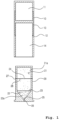
FIG. 1 is an exploded view showing an electrohydraulic microjet drug delivery device according to one embodiment of the present invention. -
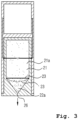
FIGS. 2 and3 are operation diagrams showing the operation of the electrohydraulic microjet drug delivery device according to one embodiment of the present invention. -
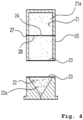
FIG. 4 is a view showing an electrohydraulic microjet drug delivery device according to another embodiment of the present invention. - Hereinafter, preferred embodiments of the present invention will be described in detail with reference to the accompanying drawings. The embodiments of the present invention may be modified in various forms. The scope of the present invention should not be construed as being limited to the embodiments described below. These embodiments are provided to specifically explain the present invention to those skilled in the art. Thus, the shape of each element shown in the drawings may be exaggerated to emphasize a clearer description.
- The terms "first", "second" and the like may be used to describe various elements. However, the elements should not be limited by these terms. The terms are used only for the purpose of distinguishing one component from another.
- The terms referred to herein are used merely for the purpose of describing particular embodiments and are not intended to limit the present invention. A singular form includes a plural form unless the context clearly dictates otherwise. In this application, the terms "include", "have" and the like are used to specify the existence of a feature, a figure, a step, an operation, an element, a part or a combination thereof described in the specification and are not intended to exclude the existence or the possibility of addition of one or more other features, figures, steps, operations, components, parts, or combinations thereof.
- As shown in
FIG. 1 , the electrohydraulic microjet drug delivery device according to one embodiment of the present invention includes adischarge body 10 and a medicinalfluid delivery body 20. - The
discharge body 10 includes apower supply unit 11 in which a certain amount of electric energy is stored, acoupling unit 14 having a space separated from thepower supply unit 11, afirst terminal 12 provided inside thecoupling unit 14, and anelectric wire 13 configured to electrically connect thefirst terminal 12 and thepower supply unit 11. Thepower supply unit 11 may include, for example, one or more capacitors. - In this regard, the
power supply unit 11 may be charged through an external power source. - The medicinal
fluid delivery body 20 includes apressure generation unit 21 configured to storepressure generation liquid 21a, a medicinalfluid storage unit 22 configured to store amedicinal fluid 22a, anelastic separation membrane 23 configured to separate thepressure generation unit 21 and the medicinalfluid storage unit 22, asecond terminal 27 provided outside the medicinal fluid delivery body so as to make contact with thefirst terminal 12,electrodes 28 disposed inside thepressure generation unit 21 and connected to thesecond terminal 27, adischarger 24 configured to connect theelectrodes 28, and anozzle 26 kept in communication with the medicinalfluid storage unit 22 and configured to inject the medicinal fluid stored in the medicinalfluid storage unit 22 to the outside. - A
check valve 25 may be installed between the medicinalfluid storage unit 22 and thenozzle 26 to prevent the medicinal fluid from flowing out of the medicinalfluid storage unit 22 until a pressure is generated. - Hereinafter, the operation of the electrohydraulic microjet drug delivery device according to one embodiment of present invention will be described with reference to
FIGS. 2 and3 . - First, as shown in
FIG. 2 , the medicinalfluid delivery body 20 is inserted into thecoupling unit 14 of thedischarge body 10. - Upon insertion, the
second terminal 27 of the medicinalfluid delivery body 20 makes contact with thefirst terminal 12 of thedischarge body 10, whereby the electric energy stored in thepower supply unit 11 is supplied to theelectrode 28. - A spark is generated by the supplied electric energy in the
discharger 24 that connects theelectrodes 28. Thus, a part of thepressure generation liquid 21a stored in thepressure generation unit 21 is instantaneously vaporized and rapidly expanded in volume. The gas may come into a plasma state of high temperature and high pressure. - Due to the pressure generated at this time, as shown in
FIG. 3 , theelastic separation membrane 23 disposed to separate thepressure generation unit 21 and the medicinalfluid storage unit 22 is rapidly expanded toward the medicinalfluid storage unit 22 to increase the pressure in the medicinalfluid storage unit 22, whereby themedicinal fluid 22a in the medicinalfluid storage unit 22 is rapidly injected through thenozzle 26. - At this time, the medicinal
fluid delivery body 20 is in contact with the skin on the side of thenozzle 26. Therefore, the injected medicinal fluid penetrates into the body through the skin. The used medicinalfluid delivery body 20 is separated from thedischarge body 10 and disposed separately, and thedischarge body 10 may be reused by charging electric energy to thepower supply unit 11. - On the other hand, a
check valve 25 may be separately installed between the medicinalfluid storage unit 22 and thenozzle 26. Although the medicinal fluid does not flow through the nozzle due to the viscosity of the medicinal fluid even without the use of thecheck valve 25, thecheck valve 25 can prevent foreign substances from penetrating into the medicinalfluid storage unit 22 through the nozzle, which makes it possible to store the medicinal fluid in a more hygienic manner. - In addition, when the
check valve 25 is not used, it is possible to block the nozzle by using a separate film or sheet on the nozzle side lower portion of the medicinal fluid delivery body. -
FIG. 4 is a view showing an electrohydraulic microjet drug delivery device according to another embodiment of the present invention. In the embodiment shown inFig. 4 , the medicinalfluid delivery body 20 is configured so that thepressure generation unit 21 for storing thepressure generation liquid 21 and the medicinalfluid storage unit 22 for storing the medicinal fluid are detachably attached to each other. Therefore, only the medicinal fluid can be separately stored and managed. This makes it possible to manage the medicinal fluid in a more hygienic manner. - The
pressure generation unit 21 and the medicinalfluid storage unit 22 may have, for example, a structure in which a protrusion and a groove are formed in a contact portion so that the upper and lower separated portions are rotated and coupled in opposite directions about an imaginary vertical axis. - In this way, the medicinal fluid can be vaporized through the use of the spark generated by the electric energy stored in the portable discharge body and can be caused to penetrate the skin. Therefore, the electrohydraulic microjet drug delivery device can be used conveniently like a general syringe, and has advantages in various aspects such as the size, the durability of use, the convenience in the storage of medicinal fluid, the environmental friendliness, and the like.
- While the present invention has been described with reference to the preferred embodiment, this description is intended to enhance the understanding of the technical contents of the present invention and is not intended to limit the technical scope of the present invention.
- It will be apparent to those skilled in the art that various modifications and variations can be made without departing from the technical scope of the present invention as defined by the appended claims.
Claims (5)
- An electrohydraulic microjet drug delivery device, comprising:a discharge body (10) provided with a power supply unit (11) in which electric energy is stored; anda medicinal fluid delivery body (20) detachably attached to the discharge body (10), the medicinal fluid delivery body (20) including a pressure generation unit (21) configured to store a pressure generation liquid (21a), a medicinal fluid storage unit (22) configured to store a medicinal fluid (22a), an elastic separation membrane (23) installed between the pressure generation unit (21) and the medicinal fluid storage unit (22) and configured to separate the pressure generation liquid (21a) and the medicinal fluid (22a), a discharger (24) installed inside the pressure generation unit (21) so as to be submerged in the pressure generation liquid (21a) and configured to generate a spark using the electric energy stored in the power supply unit (11), and a nozzle (26) kept in communication with the medicinal fluid storage unit (22),wherein when the spark is generated in the discharger (24), a part of the pressure generation liquid (21a) is vaporized and expanded to deform the elastic separation membrane (23) toward the medicinal fluid storage unit (22) so that the medicinal fluid (22a) is injected through the nozzle (26),characterized in that the device further comprises:a first terminal (12) installed on the discharge body (10) and connected to the power supply unit (11); anda second terminal (27) installed on the medicinal fluid delivery body (20) and connected to the discharger (24),wherein when the discharge body (10) and the medicinal fluid delivery body (20) are coupled, the first terminal (12) and the second terminal (27) come into contact with each other so that the electric energy stored in the power supply unit (11) is transferred to the discharger (24).
- The device according to claim 1, wherein plasma of high temperature and high pressure is generated locally in the pressure generation unit (21) by the spark generated in the discharger (24).
- The device according to claim 1, wherein the discharge body (10) includes the power supply unit (11) in which electric energy is stored, a coupling unit (14) in which the medicinal fluid delivery body (20) is detachably accommodated, and a first terminal (12) provided inside the coupling unit (14), and an electric wire (13) configured to connect the power supply unit (11) and the first terminal (12) .
- The device according to claim 1, further comprising:
a check valve (25) installed between the nozzle (26) and the medicinal fluid storage unit (22). - The device according to claim 1, wherein the medicinal fluid storage unit (22) is detachably attached to the pressure generation unit (21).
Applications Claiming Priority (2)
| Application Number | Priority Date | Filing Date | Title |
|---|---|---|---|
| KR1020180040865A KR102149190B1 (en) | 2018-04-09 | 2018-04-09 | Micro-jet drug delivery apparatus using discharge in liquid |
| PCT/KR2019/003974 WO2019198971A1 (en) | 2018-04-09 | 2019-04-04 | Electrohydraulic microjet drug delivery device |
Publications (3)
| Publication Number | Publication Date |
|---|---|
| EP3777932A1 EP3777932A1 (en) | 2021-02-17 |
| EP3777932A4 EP3777932A4 (en) | 2021-12-22 |
| EP3777932B1 true EP3777932B1 (en) | 2024-12-18 |
Family
ID=68164357
Family Applications (1)
| Application Number | Title | Priority Date | Filing Date |
|---|---|---|---|
| EP19785272.6A Active EP3777932B1 (en) | 2018-04-09 | 2019-04-04 | Electrohydraulic microjet drug delivery device |
Country Status (6)
| Country | Link |
|---|---|
| US (1) | US11883634B2 (en) |
| EP (1) | EP3777932B1 (en) |
| JP (1) | JP7083423B2 (en) |
| KR (1) | KR102149190B1 (en) |
| CN (1) | CN112368038B (en) |
| WO (1) | WO2019198971A1 (en) |
Families Citing this family (14)
| Publication number | Priority date | Publication date | Assignee | Title |
|---|---|---|---|---|
| KR102060416B1 (en) * | 2018-04-18 | 2020-02-20 | 서울대학교 산학협력단 | Micro-jet device preventing jet efficiency drop problem when repeated injection by removing metallic colloid |
| KR102255233B1 (en) | 2019-10-28 | 2021-05-24 | 주식회사 메디젯 | Medication injection device |
| KR102385578B1 (en) | 2019-10-30 | 2022-04-13 | 주식회사 메디젯 | Medication injection device |
| EP4137179A4 (en) * | 2020-04-14 | 2023-09-06 | Jeisys Medical Inc. | NEEDLE-FREE INJECTOR USING PULSE SHOCK WAVE |
| BR112022020487A2 (en) * | 2020-04-14 | 2022-11-29 | Jeisys Medical Inc | DRUG INJECTION DEVICE USING PULSED SHOCKWAVES |
| KR102406923B1 (en) | 2020-05-29 | 2022-06-10 | 주식회사 메디젯 | Medication injection device |
| KR102357165B1 (en) | 2020-06-26 | 2022-01-28 | 주식회사 메디젯 | Drug delivery apparatus |
| KR102357177B1 (en) | 2020-07-01 | 2022-01-28 | 주식회사 메디젯 | Drug delivery apparatus |
| KR102521031B1 (en) * | 2021-01-26 | 2023-04-12 | 주식회사 제이시스메디칼 | Needleless syringe based on underwater discharge using pulsed power |
| JP7758496B2 (en) * | 2021-07-27 | 2025-10-22 | ロレアル | Spark generator for generating pressure, formulation injector including a spark generator, method for generating pressure by a spark, and method for injecting a formulation |
| EP4377987A1 (en) * | 2021-07-27 | 2024-06-05 | L'oreal | Spark generator for generating pressure, formula injector comprising spark generator, method for generating pressure by spark, and method for injecting formula |
| FR3126883B1 (en) * | 2021-09-16 | 2025-06-20 | Oreal | Spark generator for generating pressure, formula injector comprising a spark generator, method for generating pressure by sparks and method for injecting formula |
| KR102787796B1 (en) * | 2023-03-08 | 2025-03-31 | 주식회사 엔스퀘어 | Micro liquid injection device with replaceable cartridge |
| WO2025028921A1 (en) * | 2023-07-28 | 2025-02-06 | 제이에스케이바이오메드 (주) | Modular pressure transfer unit and drug delivery device comprising same |
Family Cites Families (33)
| Publication number | Priority date | Publication date | Assignee | Title |
|---|---|---|---|---|
| US5037381A (en) * | 1990-07-27 | 1991-08-06 | Bock C Randolph | Electrically assisted transdermal transport device and method for renewing the device |
| US5601077A (en) * | 1991-08-07 | 1997-02-11 | Becton, Dickinson And Company | Nasal syringe sprayer with removable dose limiting structure |
| US20010027293A1 (en) * | 1999-06-29 | 2001-10-04 | Ashok V. Joshi | Storage stable fluid injection device and associated process |
| GB0012165D0 (en) * | 2000-05-20 | 2000-07-12 | Team Consulting Ltd | Portable device with consistent power output |
| FR2839198B1 (en) * | 2002-04-30 | 2004-06-04 | Thomson Licensing Sa | PLASMA VISUALIZATION PANEL WITH MICROWAVE RADIATION DISCHARGE EXCITATION |
| NZ538571A (en) | 2002-10-11 | 2007-05-31 | Idea Ag | Aggregate with increased deformability, comprising at least three amphipats, for improved transport through semi-permeable barriers and for the non-invasive drug application in vivo, especially through the skin |
| CN1777452A (en) * | 2003-04-21 | 2006-05-24 | 斯特拉塔根特生命科学 | Device and method for repeated microfluidic drug delivery |
| KR20060019518A (en) * | 2003-04-21 | 2006-03-03 | 스트라타젠트 라이프 사이언시즈 | Iterative Microjet Drug Delivery Device and Method |
| KR100539885B1 (en) * | 2003-07-10 | 2005-12-28 | 주식회사 나노어드벤스 | Apparatus for producing a metallic solution rapidly |
| CN101260873B (en) * | 2008-01-10 | 2010-12-15 | 上海交通大学 | Pulsed plasma thruster with ceramic air spout electrode |
| CN104353150A (en) * | 2008-05-08 | 2015-02-18 | 迷你泵有限责任公司 | Implantable pums and cannulas therefor |
| KR101069785B1 (en) | 2008-11-20 | 2011-10-05 | 삼성중공업 주식회사 | Purging Apparatus for Pipe Welding |
| KR101117197B1 (en) * | 2009-09-10 | 2012-03-07 | 한국전기연구원 | A device and method for liquid discharge using gas jet |
| WO2011115328A1 (en) | 2010-03-16 | 2011-09-22 | 서울대학교 산학협력단 | Microjet drug delivery system |
| WO2011115422A2 (en) * | 2010-03-16 | 2011-09-22 | 서울대학교 산학협력단 | Microjet drug delivery system and microjet injector |
| EP2481775A1 (en) | 2011-01-28 | 2012-08-01 | LANXESS Deutschland GmbH | Use of moulding materials |
| JP5829095B2 (en) * | 2011-10-20 | 2015-12-09 | 株式会社ダイセル | Syringe |
| KR20140021383A (en) | 2012-08-10 | 2014-02-20 | 서울대학교산학협력단 | Microjet trans-dermal drug injection system using er:yag laser pulse |
| KR20120096451A (en) | 2012-08-12 | 2012-08-30 | 박상구 | The process of manufacturing of electrically conductive silicone rubber heater |
| KR101500568B1 (en) * | 2013-05-30 | 2015-03-09 | 일진전기 주식회사 | Drug supply control method for microjet drug delivery device and microjet drug delivery system |
| KR101500569B1 (en) * | 2013-05-30 | 2015-03-10 | 일진전기 주식회사 | Microjet drug delivery device including elastic membrane having concave portion |
| KR101424394B1 (en) * | 2013-05-30 | 2014-07-28 | 서울대학교산학협력단 | Microjet drug delivery device having pressure means |
| KR101549966B1 (en) | 2014-02-24 | 2015-09-03 | 서울대학교산학협력단 | Microjet Drug Delivery Apparatus and Drug Delivery Method Therewith |
| KR101595405B1 (en) * | 2014-02-28 | 2016-02-18 | 주식회사 엘럽스 | Sterilization Water Generating Device |
| RU2581618C1 (en) * | 2014-10-02 | 2016-04-20 | Федеральное государственное бюджетное учреждение науки Институт электрофизики Уральского отделения Российской академии наук (ИЭФ УрО РАН) | Method of generating beams of fast electrons in gas-filled space and device therefor (versions) |
| JP6471029B2 (en) * | 2015-04-10 | 2019-02-13 | 株式会社ダイセル | Syringe |
| EP3398634B1 (en) * | 2015-12-28 | 2022-04-20 | Daicel Corporation | Administration apparatus |
| JP6676261B2 (en) * | 2016-03-04 | 2020-04-08 | 独立行政法人国立高等専門学校機構 | Shock wave generator |
| KR20170111150A (en) | 2016-03-25 | 2017-10-12 | 양천근 | Pressure sensor |
| KR101781843B1 (en) * | 2016-07-28 | 2017-09-26 | 서울대학교 산학협력단 | Microjet Drug Delivery System with Enhanced Drug Penetration Performance by Fractional Laser Pre-ablation |
| KR101838631B1 (en) * | 2016-11-03 | 2018-04-26 | 서울대학교 산학협력단 | Automatic recharging micro-jet drug injection device preventing jet speed down problem of repeated injection |
| KR101684250B1 (en) * | 2016-11-10 | 2016-12-08 | 전진우 | Needle-less drug delivery system |
| KR101834773B1 (en) | 2017-08-31 | 2018-03-06 | 제이에스케이바이오메드(주) | Micro-jet Injector |
-
2018
- 2018-04-09 KR KR1020180040865A patent/KR102149190B1/en active Active
-
2019
- 2019-04-04 US US17/045,676 patent/US11883634B2/en active Active
- 2019-04-04 CN CN201980038016.2A patent/CN112368038B/en active Active
- 2019-04-04 JP JP2021503685A patent/JP7083423B2/en active Active
- 2019-04-04 EP EP19785272.6A patent/EP3777932B1/en active Active
- 2019-04-04 WO PCT/KR2019/003974 patent/WO2019198971A1/en not_active Ceased
Also Published As
| Publication number | Publication date |
|---|---|
| US11883634B2 (en) | 2024-01-30 |
| JP7083423B2 (en) | 2022-06-10 |
| CN112368038B (en) | 2023-05-16 |
| WO2019198971A1 (en) | 2019-10-17 |
| EP3777932A1 (en) | 2021-02-17 |
| JP2021517852A (en) | 2021-07-29 |
| EP3777932A4 (en) | 2021-12-22 |
| KR102149190B1 (en) | 2020-08-28 |
| US20210023304A1 (en) | 2021-01-28 |
| CN112368038A (en) | 2021-02-12 |
| KR20190117919A (en) | 2019-10-17 |
Similar Documents
| Publication | Publication Date | Title |
|---|---|---|
| US11883634B2 (en) | Electrohydraulic microjet drug delivery device | |
| KR102060416B1 (en) | Micro-jet device preventing jet efficiency drop problem when repeated injection by removing metallic colloid | |
| CN115397491B (en) | Needleless injector using pulse shock wave | |
| KR101424394B1 (en) | Microjet drug delivery device having pressure means | |
| KR102055439B1 (en) | Micro-jet device improving jet efficiency by generating micro bubble before electric discharge | |
| US20130066263A1 (en) | Microjet drug delivery system and microjet injector | |
| KR20190122397A (en) | Micro-jet Drug Delivery System | |
| KR102629232B1 (en) | Needleless syringe based on underwater discharge using pulsed power | |
| KR20140140747A (en) | Microjet drug delivery device including elastic membrane having concave portion | |
| KR20140140739A (en) | Drug supply control method for microjet drug delivery device and microjet drug delivery system | |
| KR102406923B1 (en) | Medication injection device | |
| CN116390783B (en) | needle-free syringe | |
| KR102209397B1 (en) | Micro-jet drug delivery apparatus using discharge in liquid | |
| JP7494425B2 (en) | A drug injection device that uses pulse shock waves | |
| KR102565598B1 (en) | Micro-jet injection device capable of adjusting the amount of medicine liquid | |
| KR102385578B1 (en) | Medication injection device | |
| KR102255233B1 (en) | Medication injection device | |
| RU2810452C1 (en) | Device for administration of medicinal product using pulse shock waves | |
| KR20230085961A (en) | Valve-integrated nozzle device for microjet injection and microjet injection device including the same |
Legal Events
| Date | Code | Title | Description |
|---|---|---|---|
| STAA | Information on the status of an ep patent application or granted ep patent |
Free format text: STATUS: THE INTERNATIONAL PUBLICATION HAS BEEN MADE |
|
| PUAI | Public reference made under article 153(3) epc to a published international application that has entered the european phase |
Free format text: ORIGINAL CODE: 0009012 |
|
| STAA | Information on the status of an ep patent application or granted ep patent |
Free format text: STATUS: REQUEST FOR EXAMINATION WAS MADE |
|
| 17P | Request for examination filed |
Effective date: 20201028 |
|
| AK | Designated contracting states |
Kind code of ref document: A1 Designated state(s): AL AT BE BG CH CY CZ DE DK EE ES FI FR GB GR HR HU IE IS IT LI LT LU LV MC MK MT NL NO PL PT RO RS SE SI SK SM TR |
|
| AX | Request for extension of the european patent |
Extension state: BA ME |
|
| DAV | Request for validation of the european patent (deleted) | ||
| DAX | Request for extension of the european patent (deleted) | ||
| A4 | Supplementary search report drawn up and despatched |
Effective date: 20211123 |
|
| RIC1 | Information provided on ipc code assigned before grant |
Ipc: A61M 5/31 20060101ALI20211117BHEP Ipc: A61M 11/02 20060101ALI20211117BHEP Ipc: A61M 5/30 20060101AFI20211117BHEP |
|
| GRAP | Despatch of communication of intention to grant a patent |
Free format text: ORIGINAL CODE: EPIDOSNIGR1 |
|
| STAA | Information on the status of an ep patent application or granted ep patent |
Free format text: STATUS: GRANT OF PATENT IS INTENDED |
|
| INTG | Intention to grant announced |
Effective date: 20240802 |
|
| GRAS | Grant fee paid |
Free format text: ORIGINAL CODE: EPIDOSNIGR3 |
|
| GRAA | (expected) grant |
Free format text: ORIGINAL CODE: 0009210 |
|
| STAA | Information on the status of an ep patent application or granted ep patent |
Free format text: STATUS: THE PATENT HAS BEEN GRANTED |
|
| AK | Designated contracting states |
Kind code of ref document: B1 Designated state(s): AL AT BE BG CH CY CZ DE DK EE ES FI FR GB GR HR HU IE IS IT LI LT LU LV MC MK MT NL NO PL PT RO RS SE SI SK SM TR |
|
| REG | Reference to a national code |
Ref country code: CH Ref legal event code: EP |
|
| REG | Reference to a national code |
Ref country code: DE Ref legal event code: R096 Ref document number: 602019063710 Country of ref document: DE |
|
| REG | Reference to a national code |
Ref country code: IE Ref legal event code: FG4D |
|
| REG | Reference to a national code |
Ref country code: LT Ref legal event code: MG9D |
|
| PG25 | Lapsed in a contracting state [announced via postgrant information from national office to epo] |
Ref country code: HR Free format text: LAPSE BECAUSE OF FAILURE TO SUBMIT A TRANSLATION OF THE DESCRIPTION OR TO PAY THE FEE WITHIN THE PRESCRIBED TIME-LIMIT Effective date: 20241218 |
|
| PG25 | Lapsed in a contracting state [announced via postgrant information from national office to epo] |
Ref country code: FI Free format text: LAPSE BECAUSE OF FAILURE TO SUBMIT A TRANSLATION OF THE DESCRIPTION OR TO PAY THE FEE WITHIN THE PRESCRIBED TIME-LIMIT Effective date: 20241218 |
|
| PG25 | Lapsed in a contracting state [announced via postgrant information from national office to epo] |
Ref country code: BG Free format text: LAPSE BECAUSE OF FAILURE TO SUBMIT A TRANSLATION OF THE DESCRIPTION OR TO PAY THE FEE WITHIN THE PRESCRIBED TIME-LIMIT Effective date: 20241218 |
|
| PG25 | Lapsed in a contracting state [announced via postgrant information from national office to epo] |
Ref country code: NO Free format text: LAPSE BECAUSE OF FAILURE TO SUBMIT A TRANSLATION OF THE DESCRIPTION OR TO PAY THE FEE WITHIN THE PRESCRIBED TIME-LIMIT Effective date: 20250318 |
|
| REG | Reference to a national code |
Ref country code: NL Ref legal event code: MP Effective date: 20241218 |
|
| PG25 | Lapsed in a contracting state [announced via postgrant information from national office to epo] |
Ref country code: LV Free format text: LAPSE BECAUSE OF FAILURE TO SUBMIT A TRANSLATION OF THE DESCRIPTION OR TO PAY THE FEE WITHIN THE PRESCRIBED TIME-LIMIT Effective date: 20241218 Ref country code: GR Free format text: LAPSE BECAUSE OF FAILURE TO SUBMIT A TRANSLATION OF THE DESCRIPTION OR TO PAY THE FEE WITHIN THE PRESCRIBED TIME-LIMIT Effective date: 20250319 |
|
| PG25 | Lapsed in a contracting state [announced via postgrant information from national office to epo] |
Ref country code: RS Free format text: LAPSE BECAUSE OF FAILURE TO SUBMIT A TRANSLATION OF THE DESCRIPTION OR TO PAY THE FEE WITHIN THE PRESCRIBED TIME-LIMIT Effective date: 20250318 |
|
| PG25 | Lapsed in a contracting state [announced via postgrant information from national office to epo] |
Ref country code: NL Free format text: LAPSE BECAUSE OF FAILURE TO SUBMIT A TRANSLATION OF THE DESCRIPTION OR TO PAY THE FEE WITHIN THE PRESCRIBED TIME-LIMIT Effective date: 20241218 |
|
| REG | Reference to a national code |
Ref country code: AT Ref legal event code: MK05 Ref document number: 1751746 Country of ref document: AT Kind code of ref document: T Effective date: 20241218 |
|
| PG25 | Lapsed in a contracting state [announced via postgrant information from national office to epo] |
Ref country code: SM Free format text: LAPSE BECAUSE OF FAILURE TO SUBMIT A TRANSLATION OF THE DESCRIPTION OR TO PAY THE FEE WITHIN THE PRESCRIBED TIME-LIMIT Effective date: 20241218 |
|
| PG25 | Lapsed in a contracting state [announced via postgrant information from national office to epo] |
Ref country code: PL Free format text: LAPSE BECAUSE OF FAILURE TO SUBMIT A TRANSLATION OF THE DESCRIPTION OR TO PAY THE FEE WITHIN THE PRESCRIBED TIME-LIMIT Effective date: 20241218 |
|
| PG25 | Lapsed in a contracting state [announced via postgrant information from national office to epo] |
Ref country code: ES Free format text: LAPSE BECAUSE OF FAILURE TO SUBMIT A TRANSLATION OF THE DESCRIPTION OR TO PAY THE FEE WITHIN THE PRESCRIBED TIME-LIMIT Effective date: 20241218 |
|
| PG25 | Lapsed in a contracting state [announced via postgrant information from national office to epo] |
Ref country code: IS Free format text: LAPSE BECAUSE OF FAILURE TO SUBMIT A TRANSLATION OF THE DESCRIPTION OR TO PAY THE FEE WITHIN THE PRESCRIBED TIME-LIMIT Effective date: 20250418 |
|
| PG25 | Lapsed in a contracting state [announced via postgrant information from national office to epo] |
Ref country code: PT Free format text: LAPSE BECAUSE OF FAILURE TO SUBMIT A TRANSLATION OF THE DESCRIPTION OR TO PAY THE FEE WITHIN THE PRESCRIBED TIME-LIMIT Effective date: 20250421 |
|
| PG25 | Lapsed in a contracting state [announced via postgrant information from national office to epo] |
Ref country code: EE Free format text: LAPSE BECAUSE OF FAILURE TO SUBMIT A TRANSLATION OF THE DESCRIPTION OR TO PAY THE FEE WITHIN THE PRESCRIBED TIME-LIMIT Effective date: 20241218 |
|
| PGFP | Annual fee paid to national office [announced via postgrant information from national office to epo] |
Ref country code: FR Payment date: 20250428 Year of fee payment: 7 |
|
| PG25 | Lapsed in a contracting state [announced via postgrant information from national office to epo] |
Ref country code: RO Free format text: LAPSE BECAUSE OF FAILURE TO SUBMIT A TRANSLATION OF THE DESCRIPTION OR TO PAY THE FEE WITHIN THE PRESCRIBED TIME-LIMIT Effective date: 20241218 Ref country code: AT Free format text: LAPSE BECAUSE OF FAILURE TO SUBMIT A TRANSLATION OF THE DESCRIPTION OR TO PAY THE FEE WITHIN THE PRESCRIBED TIME-LIMIT Effective date: 20241218 |
|
| PG25 | Lapsed in a contracting state [announced via postgrant information from national office to epo] |
Ref country code: SK Free format text: LAPSE BECAUSE OF FAILURE TO SUBMIT A TRANSLATION OF THE DESCRIPTION OR TO PAY THE FEE WITHIN THE PRESCRIBED TIME-LIMIT Effective date: 20241218 |
|
| PG25 | Lapsed in a contracting state [announced via postgrant information from national office to epo] |
Ref country code: CZ Free format text: LAPSE BECAUSE OF FAILURE TO SUBMIT A TRANSLATION OF THE DESCRIPTION OR TO PAY THE FEE WITHIN THE PRESCRIBED TIME-LIMIT Effective date: 20241218 |
|
| PG25 | Lapsed in a contracting state [announced via postgrant information from national office to epo] |
Ref country code: IT Free format text: LAPSE BECAUSE OF FAILURE TO SUBMIT A TRANSLATION OF THE DESCRIPTION OR TO PAY THE FEE WITHIN THE PRESCRIBED TIME-LIMIT Effective date: 20241218 |
|
| PG25 | Lapsed in a contracting state [announced via postgrant information from national office to epo] |
Ref country code: SE Free format text: LAPSE BECAUSE OF FAILURE TO SUBMIT A TRANSLATION OF THE DESCRIPTION OR TO PAY THE FEE WITHIN THE PRESCRIBED TIME-LIMIT Effective date: 20241218 |
|
| REG | Reference to a national code |
Ref country code: DE Ref legal event code: R097 Ref document number: 602019063710 Country of ref document: DE |
|
| PG25 | Lapsed in a contracting state [announced via postgrant information from national office to epo] |
Ref country code: DK Free format text: LAPSE BECAUSE OF FAILURE TO SUBMIT A TRANSLATION OF THE DESCRIPTION OR TO PAY THE FEE WITHIN THE PRESCRIBED TIME-LIMIT Effective date: 20241218 |
|
| PLBE | No opposition filed within time limit |
Free format text: ORIGINAL CODE: 0009261 |
|
| STAA | Information on the status of an ep patent application or granted ep patent |
Free format text: STATUS: NO OPPOSITION FILED WITHIN TIME LIMIT |
|
| REG | Reference to a national code |
Ref country code: CH Ref legal event code: L10 Free format text: ST27 STATUS EVENT CODE: U-0-0-L10-L00 (AS PROVIDED BY THE NATIONAL OFFICE) Effective date: 20251029 |
|
| REG | Reference to a national code |
Ref country code: DE Ref legal event code: R119 Ref document number: 602019063710 Country of ref document: DE |
|
| REG | Reference to a national code |
Ref country code: CH Ref legal event code: H13 Free format text: ST27 STATUS EVENT CODE: U-0-0-H10-H13 (AS PROVIDED BY THE NATIONAL OFFICE) Effective date: 20251125 |
|
| 26N | No opposition filed |
Effective date: 20250919 |
|
| PG25 | Lapsed in a contracting state [announced via postgrant information from national office to epo] |
Ref country code: LU Free format text: LAPSE BECAUSE OF NON-PAYMENT OF DUE FEES Effective date: 20250404 |
|
| PG25 | Lapsed in a contracting state [announced via postgrant information from national office to epo] |
Ref country code: MC Free format text: LAPSE BECAUSE OF FAILURE TO SUBMIT A TRANSLATION OF THE DESCRIPTION OR TO PAY THE FEE WITHIN THE PRESCRIBED TIME-LIMIT Effective date: 20241218 |
|
| GBPC | Gb: european patent ceased through non-payment of renewal fee |
Effective date: 20250404 |
|
| REG | Reference to a national code |
Ref country code: BE Ref legal event code: MM Effective date: 20250430 |
|
| PG25 | Lapsed in a contracting state [announced via postgrant information from national office to epo] |
Ref country code: DE Free format text: LAPSE BECAUSE OF NON-PAYMENT OF DUE FEES Effective date: 20251104 |
|
| PG25 | Lapsed in a contracting state [announced via postgrant information from national office to epo] |
Ref country code: GB Free format text: LAPSE BECAUSE OF NON-PAYMENT OF DUE FEES Effective date: 20250404 |
|
| PG25 | Lapsed in a contracting state [announced via postgrant information from national office to epo] |
Ref country code: BE Free format text: LAPSE BECAUSE OF NON-PAYMENT OF DUE FEES Effective date: 20250430 |
|
| PG25 | Lapsed in a contracting state [announced via postgrant information from national office to epo] |
Ref country code: CH Free format text: LAPSE BECAUSE OF NON-PAYMENT OF DUE FEES Effective date: 20250430 |
|
| PG25 | Lapsed in a contracting state [announced via postgrant information from national office to epo] |
Ref country code: IE Free format text: LAPSE BECAUSE OF NON-PAYMENT OF DUE FEES Effective date: 20250404 |
|
| PG25 | Lapsed in a contracting state [announced via postgrant information from national office to epo] |
Ref country code: CY Free format text: LAPSE BECAUSE OF FAILURE TO SUBMIT A TRANSLATION OF THE DESCRIPTION OR TO PAY THE FEE WITHIN THE PRESCRIBED TIME-LIMIT Effective date: 20241218 |
|
| PG25 | Lapsed in a contracting state [announced via postgrant information from national office to epo] |
Ref country code: LT Free format text: LAPSE BECAUSE OF FAILURE TO SUBMIT A TRANSLATION OF THE DESCRIPTION OR TO PAY THE FEE WITHIN THE PRESCRIBED TIME-LIMIT Effective date: 20241218 |