EP3777753B1 - Implant with high primary stability and accelerated secondary stability - Google Patents
Implant with high primary stability and accelerated secondary stability Download PDFInfo
- Publication number
- EP3777753B1 EP3777753B1 EP19218309.3A EP19218309A EP3777753B1 EP 3777753 B1 EP3777753 B1 EP 3777753B1 EP 19218309 A EP19218309 A EP 19218309A EP 3777753 B1 EP3777753 B1 EP 3777753B1
- Authority
- EP
- European Patent Office
- Prior art keywords
- implant
- crest
- root
- flank
- roughened
- Prior art date
- Legal status (The legal status is an assumption and is not a legal conclusion. Google has not performed a legal analysis and makes no representation as to the accuracy of the status listed.)
- Active
Links
Images



Classifications
-
- B—PERFORMING OPERATIONS; TRANSPORTING
- B24—GRINDING; POLISHING
- B24C—ABRASIVE OR RELATED BLASTING WITH PARTICULATE MATERIAL
- B24C1/00—Methods for use of abrasive blasting for producing particular effects; Use of auxiliary equipment in connection with such methods
- B24C1/04—Methods for use of abrasive blasting for producing particular effects; Use of auxiliary equipment in connection with such methods for treating only selected parts of a surface, e.g. for carving stone or glass
-
- A—HUMAN NECESSITIES
- A61—MEDICAL OR VETERINARY SCIENCE; HYGIENE
- A61C—DENTISTRY; APPARATUS OR METHODS FOR ORAL OR DENTAL HYGIENE
- A61C8/00—Means to be fixed to the jaw-bone for consolidating natural teeth or for fixing dental prostheses thereon; Dental implants; Implanting tools
- A61C8/0012—Means to be fixed to the jaw-bone for consolidating natural teeth or for fixing dental prostheses thereon; Dental implants; Implanting tools characterised by the material or composition, e.g. ceramics, surface layer, metal alloy
-
- A—HUMAN NECESSITIES
- A61—MEDICAL OR VETERINARY SCIENCE; HYGIENE
- A61C—DENTISTRY; APPARATUS OR METHODS FOR ORAL OR DENTAL HYGIENE
- A61C8/00—Means to be fixed to the jaw-bone for consolidating natural teeth or for fixing dental prostheses thereon; Dental implants; Implanting tools
- A61C8/0018—Means to be fixed to the jaw-bone for consolidating natural teeth or for fixing dental prostheses thereon; Dental implants; Implanting tools characterised by the shape
- A61C8/0037—Details of the shape
- A61C8/0039—Details of the shape in the form of hollow cylinder with an open bottom
-
- A—HUMAN NECESSITIES
- A61—MEDICAL OR VETERINARY SCIENCE; HYGIENE
- A61C—DENTISTRY; APPARATUS OR METHODS FOR ORAL OR DENTAL HYGIENE
- A61C13/00—Dental prostheses; Making same
- A61C13/0003—Making bridge-work, inlays, implants or the like
- A61C13/0006—Production methods
- A61C13/0007—Production methods using sand blasting
-
- A—HUMAN NECESSITIES
- A61—MEDICAL OR VETERINARY SCIENCE; HYGIENE
- A61C—DENTISTRY; APPARATUS OR METHODS FOR ORAL OR DENTAL HYGIENE
- A61C8/00—Means to be fixed to the jaw-bone for consolidating natural teeth or for fixing dental prostheses thereon; Dental implants; Implanting tools
- A61C8/0018—Means to be fixed to the jaw-bone for consolidating natural teeth or for fixing dental prostheses thereon; Dental implants; Implanting tools characterised by the shape
- A61C8/0037—Details of the shape
- A61C2008/0046—Textured surface, e.g. roughness, microstructure
-
- A—HUMAN NECESSITIES
- A61—MEDICAL OR VETERINARY SCIENCE; HYGIENE
- A61C—DENTISTRY; APPARATUS OR METHODS FOR ORAL OR DENTAL HYGIENE
- A61C8/00—Means to be fixed to the jaw-bone for consolidating natural teeth or for fixing dental prostheses thereon; Dental implants; Implanting tools
- A61C8/0018—Means to be fixed to the jaw-bone for consolidating natural teeth or for fixing dental prostheses thereon; Dental implants; Implanting tools characterised by the shape
- A61C8/0022—Self-screwing
- A61C8/0024—Self-screwing with self-boring cutting edge
-
- A—HUMAN NECESSITIES
- A61—MEDICAL OR VETERINARY SCIENCE; HYGIENE
- A61F—FILTERS IMPLANTABLE INTO BLOOD VESSELS; PROSTHESES; DEVICES PROVIDING PATENCY TO, OR PREVENTING COLLAPSING OF, TUBULAR STRUCTURES OF THE BODY, e.g. STENTS; ORTHOPAEDIC, NURSING OR CONTRACEPTIVE DEVICES; FOMENTATION; TREATMENT OR PROTECTION OF EYES OR EARS; BANDAGES, DRESSINGS OR ABSORBENT PADS; FIRST-AID KITS
- A61F2250/00—Special features of prostheses classified in groups A61F2/00 - A61F2/26 or A61F2/82 or A61F9/00 or A61F11/00 or subgroups thereof
- A61F2250/0014—Special features of prostheses classified in groups A61F2/00 - A61F2/26 or A61F2/82 or A61F9/00 or A61F11/00 or subgroups thereof having different values of a given property or geometrical feature, e.g. mechanical property or material property, at different locations within the same prosthesis
- A61F2250/0025—Special features of prostheses classified in groups A61F2/00 - A61F2/26 or A61F2/82 or A61F9/00 or A61F11/00 or subgroups thereof having different values of a given property or geometrical feature, e.g. mechanical property or material property, at different locations within the same prosthesis differing in roughness
Definitions
- the present disclosure relates to improvements in screw-type dental implants and, in particular, to dental implants having a roughened surface topography and methods of making the same.
- Dental implants are often comprised of metal and metal alloys, including titanium (Ti) and titanium alloys.
- Ti titanium
- the dental implant serves as an artificial root that integrates with the gingiva and the bone tissue of the mouth.
- osseointegration For the dental implant to function successfully, sufficient osseointegration is required. In other words, a bond between the implant and the bone must be formed and retained.
- the surface of the implant may be roughened to help enhance the osseointegration process.
- processes for roughening an implant surface include acid etching, grit blasting, or a combination thereof, which impart roughness on the surface.
- Roughening the surface of an implant can lead to a compromise in the integrity of the implant's cutting geometry. More specifically, roughening the crests of the implant's thread can lead to rolling the edge of the crests and/or eroding the peaks of the crests. Additionally, roughening of the crests can change the machined macro geometry (or thread features) intended to initially stabilize the implant. Robust initial stability is a requirement for long-term stability (permanent fixation of the implant), and without it, the implant can be more susceptible to non integration or even loss of integration, both of which generally require implant retrieval. Furthermore, the change in macrogeometry can alter the tactile feedback felt by a clinician during implant placement.
- WO 2004/098442 A1 discloses a bone implant with an implant body which has a screw thread on its circumference for screwing the implant body into the human bone.
- the implant has a surface comprising a biocompatible structure.
- An implant for implantation into bone tissue includes an elongated body.
- the elongated body has an upper portion configured to receive a prosthesis and a lower portion for being submerged in the bone tissue.
- the elongated body of the implant also includes an outer surface.
- the implant also includes at least one thread on the outer surface of the body. The thread makes a number of turns around the body between the upper and lower portions and includes a root, a flank, and a crest. The root and a segment of the flank have a roughened portion compared to the crest.
- another implant for implantation into bone tissue includes at least one thread.
- the thread makes a number of turns around the implant.
- the implant also includes a roughened portion adjacent to a root of the thread, and the roughened portion extends along a length of the implant while a crest of the thread remains relatively smooth.
- a method of forming an implant having a threaded outer surface including a root, a flank, and a crest includes treating the threaded outer surface. More specifically, the method includes treating the threaded outer surface at only the root and a portion of the flank while the crest remains untreated.
- the root and a segment of the flank of the implant have an acid etched surface so that the root and a segment of the flank have a roughened portion relative to the crest.
- FIG. 1 illustrates a side view of an implant 10 according to a first implementation.
- the implant 10 may, for example, be made of titanium or alloys thereof.
- FIGS. 2 , 3 , 4 , and 5 which are discussed below, describe alternative implant designs that may also be used according to certain implementations of the disclosed subject matter.
- the implant 10 has an elongated body.
- the top of the elongated body includes a head portion 12, which includes a non-rotational boss 14.
- the boss 14 is hexagonal.
- the boss 14 is configured to be engageable with a tool that screws the implant 10 into bone tissue.
- the boss 14 is also used for non-rotationally engaging a correspondingly-shaped socket on a restorative or prosthetic component (e.g., an abutment with a tooth-shaped crown attached thereto) that is attached to the implant 10.
- the head portion 12 also includes a collar 16.
- a threaded bottom portion 20 facilitates bonding with bone or gingiva.
- the threaded bottom portion 20 includes a thread 22 that makes a plurality of turns around the implant 10. The turns are typically in a helical pattern, as shown in FIG. 1 .
- the threaded bottom portion 20 may include multiple threads, so as to define a multi-lead thread.
- each of the turns of the thread 22 includes a root region, a flank region and a crest region.
- the root region of a turn in the thread 22 is located at a minor diameter with respect to a central axis of the implant 10, while the crest region is located at a major diameter with respect to the central axis of the implant 10.
- the flank region is the surface connecting the root and the crest regions.
- the crest region provides primary stability for the implant 10 by ensuring a secure mechanical connection between the implant 10 and the bone or gingiva. Different implementations of the root, flank and crest regions will be described in detail with respect to FIGS. 7A-7C and 8A-8C .
- the threaded bottom portion 20 may further include a self-tapping region 24 with incremental cutting edges that allows the implant 10 to be installed without the need for a bone tap.
- the thread 22 includes a roughened portion 30.
- the roughened portion 30 can aid in the osscointegration process by improving the integration between bone or gingiva and the implant 10. This improved integration provides a secondary level of stability for the implant.
- the roughened portion 30 may be generated using a variety of techniques including, for example, acid etching, grit blasting, or a combination thereof. As described below, the preferred roughening technique is grit blasting. As illustrated in FIG. 1 , the roughened portion 30 is located on the root and flank regions of the thread 22, but not on the crest regions. A transition region from the roughened portion to the relatively smoother surface occurs along the thread's flank regions between the root and crest regions.
- the transition region includes a portion of varying roughness in the direction of the crest.
- the transition region includes a portion of decreasing roughness in the direction of the crest. That is, the transition region decreases in roughness as it approaches the relatively smooth crest.
- the self-tapping region 24 of the implant 10 is relatively smooth compared to the roughened portion 30.
- a transition point between the roughened portion 30 and the relatively smooth surface of the crest can be chosen to minimize interference with the surface of the crest regions while maximizing osseointegration with the roughened portions on the root and flank regions.
- different transition points can be chosen for different thread geometries.
- FIG. 2 illustrates an implant 110 that differs in physical features from the implant 10 of FIG. 1 to allow it to extend through the gingiva.
- the threads of the implant 110 are in a helical pattern.
- the implant 110 also includes an elongated middle section 112 that is relatively smooth compared to the roughened portion 130. Similar to the self-tapping region 24 of FIG. 1 , the self-tapping region 124 illustrated in FIG. 2 is also relatively smooth compared to the roughened portion 130.
- the implant 110 also differs from the implant 10 in the details of the roughened portion 130. More specifically, the roughened portion 130 extends up a smaller portion of the flank regions of the implant 110 compared to the roughened portion 30 of the implant 10 of FIG. 1 .
- the transition point between the roughened portion and the relatively smooth surface of the implant 110 can be chosen to minimize interference with the cutting surface of the crest regions while maximizing osseointegration with the roughened surfaces on the root and flank regions.
- FIG. 3 illustrates a more typical trans-gingival implant 210 that differs from the implant 10 of FIG. 1 and the implant 110 of FIG. 2 in the details of the contours of the threads defining the exterior of the threaded bottom portion 220.
- the implant 210 has a roughened portion 230 which is located on the root regions and portions of the flank regions of the implant 210.
- the threads of the implant 210 are also in a helical pattern.
- the threads of the implant 210 have portions 235 of their crests truncated, as described in U.S. Patent No. 5,902,109 , which is hereby explicitly mentioned.
- FIG. 4 illustrates an implant 310 that includes two threadless regions 350, 360 interspersed between multiple threaded regions 320, 330, 340.
- the threaded regions 320, 330, 340 include threads in a helical pattern and are similar to the threaded regions, 20, 120, 220 described above with respect to FIGS. 1-3 in that the threaded regions 320, 330, 340 include roughened surfaces located on their root regions and portions of their flank regions.
- the threadless regions 350, 360 also include roughened surfaces. As discussed above with respect to FIG. 1 , the roughened surfaces provide the implant 310 with a secondary level of stability to help secure the implant after installation. Because the threadless regions 350, 360 lack threads with crests, the entirety of the threadless regions 350,360 can be roughened without requiring a relatively smoother crest area, as required by the implants of FIGS. 1-3 . Further, although the implants of FIGS. 1-3 have smooth self-tapping regions, in certain implementations, the root and flank regions of threads in the self-tapping region may be roughened to further increase implant stability, as shown in FIG. 4 . As shown in FIG. 4 , the crests of these threaded portions in the self-tapping region remain smooth.
- FIG. 5 illustrates a trans-gingival implant 410 that differs from the implant 10 of FIG. 1 in the details of the configuration of the thread 412 along the exterior of the threaded bottom portion and in the inclusion of a vertical groove 414 extending up the length of the implant 410.
- the thread 412 has a larger lead compared to the leads illustrated in FIGS. 1-4 , which effectively increases the size of the root regions relative to the crest regions of the thread 412. Because the root regions of the thread 412 are larger, the implant 410 has more of its surface roughened compared to the implants shown in FIGS. 1-4 .
- the implant 410 has an extended vertical groove 414 compared to the implants of FIGS. 1-4 .
- the vertical groove 414 is roughened and further improves osseointegration to the implant 410.
- FIG. 6 illustrates an abutment 420 configured to attach to both an implant (e.g., one of the implants illustrated in FIGS. 1-5 ) and to receive a tooth-shaped crown (not shown).
- the abutment 420 includes an upper portion 422 shaped to receive and securely attach to a dental crown that is typically porcelain. In other implementations, other shapes may be used for the upper portion.
- the abutment 420 also includes a lower portion 424, which attaches to an implant through an internal socket (not shown) that would be non-rotationally coupled to an external anti-rotational feature of the implant, such as the hexagonal boss 14 on the implant 10 of FIG. 1 .
- a screw extends through the abutment 420 and engages the internal threads within the bore of the implant to axially secure the abutment 420 on the implant, as is well known in the art.
- the abutment 420 also includes threads 426 on the lower portion 424, which are similar to the threaded portions of the implants described above with respect to FIGS. 1-5 .
- the threads 426 on the abutment 420 include roughened surfaces 428 in the root and flank regions of the threads 426, while the crest regions of the threads 426 remain relatively smooth.
- the threads 426 on the abutment 420 are significantly smaller than the threads on the implants described above with respect to FIGS. 1-5 .
- the threads 426 and the roughened surfaces 428 help to promote gingival tissue attachment to the surface of the abutment 420.
- implants according to the disclosed subject matter include at least one thread with portions of varying roughness.
- the thread can include one or more turns around the central axis of the implants, and each turn can include a root region, a flank region and a crest region.
- the root region of a turn in thread is located at a minor diameter with respect to the central axis of the implant while the crest region is located at a major diameter with respect to the central axis.
- the flank region serves as a transition region between the root and the crest regions.
- the root, flank and crest regions can have different shapes and can extend at different angles with respect to each other.
- FIGS. 7A-7C illustrate side views of the threaded portion of various implants with differently shaped roots according to the disclosed subject matter.
- Each of the threaded implant portions illustrated in FIGS. 7A-7C includes at least one root, flank, and crest.
- the threaded portion of FIG. 7A includes crests 510a and roots 520a, each with a flattened shape, and multiple flanks 530a connecting the crests 510a and roots 520a.
- Each of the flanks 530a has a length 'L 1 ', and a segment of each flank 530a, each segment with a length 'R 1 ', has a roughened portion.
- the length of the roughened segment, R 1 can be chosen based on performance requirements and the geometry of a particular implant.
- the length R 1 may be chosen to achieve an acceptable balance between the increased stability offered by the roughened portion and the increase in insertion torque required to install the implant.
- the roughened portion is on an inner section of each of the flanks 530a relative to a central axis of the implant (central axis not shown).
- an outer section of each of the flanks 530a (relative to the central axis) has a surface similar to the crests 510a, which is smoother relative to the roughened portion.
- the threaded portions of FIG. 7A include transition regions from the roughened portion to the relatively smoother portions of the flanks 530a and crests 510a.
- the transition region can optionally include a portion of varying roughness in the direction of the crest 510a.
- the entire roughened portion can have a similar roughness.
- the threaded portion of FIG. 7B is similar to the threaded portion illustrated in FIG. 7A , but includes curved roots 520b instead of flattened roots. Further, each of the flanks 530b has a length 'L 2 ', and a segment of each flank 530b has a roughened portion of length 'R 2 ' that is longer than 'R 1 '. Like the roughened portions described above with respect to FIG. 7A , each roughened portion illustrated in FIG. 7B is on an inner section of each of the flanks relative to a central axis of the implant (central axis not shown), and an outer section of each of the flanks (relative to the central axis) has roughness similar to the crests.
- the flattened crests 510b of FIG. 7B are similar to the crests 510a of FIG. 7A .
- the threaded portion of FIG. 7C is similar to the threaded portion illustrated in FIGS. 7A and 7B , but includes narrower angled roots 520c instead of flattened or curved roots. Further, each of the flanks 530c has a length 'L 3 ', and a segment of each flank 530c has a roughened portion with a length 'R 3 '. Like the roughened portions described above with respect to FIGS. 7A and 7B , each roughened portion illustrated in FIG. 7C is on an inner section of each of the flanks relative to a central axis of the implant (central axis not shown), and an outer section of each of the flanks (relative to the central axis) has roughness similar to the crests. The crests 510c of FIG. 7C are similar to the crests 510a of FIG. 7A and the crests 510b of FIG. 7B .
- FIGS. 8A-8C illustrate side views of the threaded portion of implants with differently shaped crests according to the disclosed subject matter.
- Each of the threaded implant portions illustrated in FIGS. 8A-8C includes at least one root, flank, and crest.
- the threaded portion of FIG. 8A includes crests 610a and roots 620a, each with a flattened shape, and multiple flanks 630a connecting the crests 610a and roots 620a.
- Each of the flanks 630a in the threaded portion of FIG. 8A has a length 'L 4 ', and a segment of each flank 630a has a roughened portion with a length 'R 4 '. As shown in FIG.
- the roughened portion of the implant in FIG. 8A is on an inner section of each of the flanks 630a relative to a central axis of the implant (central axis not shown). Further, an outer section of each of the flanks 630a (relative to the central axis) has roughness similar to the crests 610a.
- the threaded portion of FIG. 8B is similar to the threaded portion illustrated in FIG. 8A , but includes curved crests 610b instead of flattened crests. Further, each of the flanks 630b has a length 'L 5 ', and a segment of each flank 630b has a roughened portion with a length 'R 5 '. Like the roughened portions described above with respect to FIG. 8A , each roughened portion illustrated in FIG. 8B is on an inner section of each of the flanks 630b relative to a central axis of the implant (central axis not shown), and an outer section of each of the flanks 630b (relative to the central axis) has roughness similar to the crests 610b.
- the roots 620b of FIG. 8B are similar to the roots 620a of FIG.6A.
- the threaded portion of FIG. 8C is similar to the threaded portion illustrated in FIGS. 8A and 8B , but includes peaked crests 610c instead of flattened or curved crests. Further, each of the flanks 630c has a length 'L 6 ', and a segment of each flank 630c has a roughened portion with a length 'R 6 '. Like the roughened portions described above with respect to FIGS. 8A and 8B , each roughened portion illustrated in FIG.
- each of the flanks 630c is on an inner section of each of the flanks 630c relative to a central axis of the implant (central axis not shown), and an outer section of each of the flanks (relative to the central axis) has roughness similar to the crests 610c.
- the roots 620c of FIG. 8C are similar to the roots 620a of FIG.8A and the roots 620b of FIG. 8B .
- a nozzle 640 is placed between the root and crest regions of the threaded portion.
- the nozzle 640 is used to perform grit blasting on the threaded portion and to appropriately roughen the threaded portion's surface.
- the nozzle 640 can be guided by a laser or another optical or imaging device (not shown) that identifies the specific location of the nozzle 640 relative to the thread structure such that the blasting occurs between crest regions in a helical pattern along the root regions.
- the laser or imaging device can identify and track the locations of the crests of two adjacent turns of the thread to ensure that the nozzle 640 remains substantially at the midpoint between those two adjacent crests.
- a mask can be used to cover portions of the threaded portion in order to cover up areas that should not be treated or roughened.
- threaded implant portions as disclosed herein can have different shapes and sizes. More specifically, the flank regions connecting the root and the crest regions of the threaded portions can have different lengths and extend at different angles with respect to each other. Generally speaking the lengths of the flank regions range from 0.05 mm to 1 mm. In one preferred implementation, the length of the flank region is in the range from 0.1 mm to 0.3 mm. Further, in a preferred implementation, up to 95 percent of the flank region can be roughened. In other implementations, the roughened portion makes up about 50% of the length of the flank region, in addition to the adjacent surface at the thread's root. In an implementation requiring less roughening, the roughened portion makes up about 25% of the length of the flank region, in addition to the adjacent surface at the thread's root. Other percentages of the flank region can roughened in other implementations.
- the roughened portions of threads according to the disclosed subject matter can be asymmetrical. That is, opposing flanks within a single turn of a thread can have roughened portions with different lengths. Additionally, the lengths of roughened portions within a thread can generally increase or decrease in a direction moving from the bottom of the thread towards the top of the thread. Portions of the implant that integrate with dense cortical bone can have increased roughness compared to portions of the implant that integrate with softer cancellous bone.
- elements of the implementations in FIGS. 7A-7C and FIGS. 8A-8C may be combined with each other in accordance with the described subject matter.
- different crest and root shapes as disclosed herein may be combined with each other as appropriate to form threads for implants as appropriate.
- crest and root shapes other than those depicted in FIGS. 7A-7C and FIGS. 8A-8C may be incorporated in certain implementations of the disclosed subject matter.
- flank shapes other than those depicted in FIGS. 7A-7C and FIGS. 8A-8C may be incorporated in other implementations of the disclosed subject matter.
- certain implementations may incorporate convex flanks, concave flanks, wavelike flanks, or any other appropriate flank shape.
- FIG. 9 is a flow diagram illustrating a method of forming an implant according to the disclosed subject matter.
- an implant having a threaded outer surface is provided. Each thread includes at least one turn around the implant, and each turn has at least one root, one flank, and one crest.
- the implant is comprised of titanium, a titanium alloy, or the like.
- the outer surface of the implant is treated such that only the root and a portion of the flank are roughened while the crest remains untreated.
- the crest may be lightly treated compared to the root and the portion of the flank.
- the crest may be lightly acid etched while the root and the portion of the flank are more heavily acid etched.
- only a portion of the length of the implant may be treated such that only some of the turns of the threads have roughened portions at their root regions.
- only a fraction of the turns (e.g., one half of the turns) of the threaded outer surface may be treated along the lower portion of the implant, while the remainder of the threaded outer surface remains untreated.
- Treating the outer surface at step 701 may include blasting the outer surface.
- the blasting can optionally be performed using a blast nozzle.
- the blast nozzle can be inserted in between adjacent crests of the implant in order to treat only the desired region or regions.
- the blasting may be performed along a helical locus of the outer surface.
- other treatment methods may be used.
- the surface may be acid etched to create a roughened surface on the desired roots and/or flanks of the implant's outer surface.
- the blast nozzle can blast different types of materials, and the different types of materials can have different particle sizes to produce different roughnesses on the outer surface of the implant.
- calcium phosphate particles can be used as a blast material to treat the outer surface of an implant.
- the calcium phosphate particles can range in size, for example, from 150-425 microns.
- other variables such as, for example, particle shape, particle hardness, particle flow rate, the size of the blast nozzle, the distance between the blast nozzle and the surface of the implant, the angle at which the nozzle is placed, and the type of gas used to accelerate the blasted materials can affect the roughness of the implant's outer surface.
- the outer surface of the implant can undergo a second optional treatment at step 702.
- the further treatment can include treatment of the crest, flank and root regions with an acid etching treatment, which provides the outer surface of the implant with additional roughness.
- an acid etching treatment for example, in implementations where the implant is made of commercially pure titanium, a mixture including both hydrochloric acid and sulfuric acid may be used to perform acid etching, as described in U.S. Patent No. 7,857,987 , which is hereby explicitly mentioned.
- a mixture including both hydrochloric acid and hydrofluoric acid can be used to perform acid etching, as described in U.S. Patent No. 8,251,700 , which is hereby also mentioned.
- the entire threaded region has some roughness, with the crest regions remaining relatively smooth compared to the root regions and portions of the flank regions.
- the surface roughness, Ra can be in the range of 0.7-1.6 microns along the root regions and flank regions that have been both grit-blasted and acid-etched, while the surface roughness, Ra, can be in the range of 0.3-0.7 microns along the crest regions that have been only acid-etched.
- the surface roughness, Ra is about 1.3 microns along the root regions and flank regions that have been both grit blasted and acid etched, while the surface roughness, Ra, is about 0.5 microns along the crest regions that have been only acid etched.
- the surface roughness is preferably measured via the inverse Fourier transform (IFFT) method.
Landscapes
- Health & Medical Sciences (AREA)
- Veterinary Medicine (AREA)
- Oral & Maxillofacial Surgery (AREA)
- Life Sciences & Earth Sciences (AREA)
- Animal Behavior & Ethology (AREA)
- General Health & Medical Sciences (AREA)
- Public Health (AREA)
- Dentistry (AREA)
- Epidemiology (AREA)
- Engineering & Computer Science (AREA)
- Orthopedic Medicine & Surgery (AREA)
- Mechanical Engineering (AREA)
- Manufacturing & Machinery (AREA)
- Ceramic Engineering (AREA)
- Dental Prosthetics (AREA)
- Cardiology (AREA)
- Transplantation (AREA)
- Biomedical Technology (AREA)
- Heart & Thoracic Surgery (AREA)
- Vascular Medicine (AREA)
Description
- This application claims priority to and the benefits of
United States Provisional Patent Application No. 61/978,731, filed April 11, 2014 - A portion of the disclosure of this patent document contains material which is subject to copyright protection. The copyright owner has no objection to the facsimile reproduction by anyone of the patent disclosure, as it appears in the Patent and Trademark Office patent files or records, but otherwise reserves all copyright rights whatsoever.
- The present disclosure relates to improvements in screw-type dental implants and, in particular, to dental implants having a roughened surface topography and methods of making the same.
- It is becoming more common to replace a missing tooth with a prosthetic tooth that is placed upon and attached to a dental implant. Dental implants are often comprised of metal and metal alloys, including titanium (Ti) and titanium alloys. The dental implant serves as an artificial root that integrates with the gingiva and the bone tissue of the mouth.
- For the dental implant to function successfully, sufficient osseointegration is required. In other words, a bond between the implant and the bone must be formed and retained. The surface of the implant may be roughened to help enhance the osseointegration process. Non-limiting examples of processes for roughening an implant surface include acid etching, grit blasting, or a combination thereof, which impart roughness on the surface.
- Roughening the surface of an implant, however, can lead to a compromise in the integrity of the implant's cutting geometry. More specifically, roughening the crests of the implant's thread can lead to rolling the edge of the crests and/or eroding the peaks of the crests. Additionally, roughening of the crests can change the machined macro geometry (or thread features) intended to initially stabilize the implant. Robust initial stability is a requirement for long-term stability (permanent fixation of the implant), and without it, the implant can be more susceptible to non integration or even loss of integration, both of which generally require implant retrieval. Furthermore, the change in macrogeometry can alter the tactile feedback felt by a clinician during implant placement. This is critical, as the "feel" of the implant during installation can serve as a directional indicator by which additional clinical decisions are made (e.g., restore the implant immediately, delay loading of the implant, remove the implant, place additional torque on the implant post-seating, etc.). Unfortunately, a change in tactile feedback, such as what could result from small changes in macrogeometry, can create a false positive or false negative, and can leave the clinician misinformed.
-
WO 2004/098442 A1 discloses a bone implant with an implant body which has a screw thread on its circumference for screwing the implant body into the human bone. The implant has a surface comprising a biocompatible structure. - The present invention is defined by the appended independent product claim 1 and independent method claim 13. Preferred embodiments are defined in the dependent claims.
- An implant for implantation into bone tissue includes an elongated body. The elongated body has an upper portion configured to receive a prosthesis and a lower portion for being submerged in the bone tissue. The elongated body of the implant also includes an outer surface. The implant also includes at least one thread on the outer surface of the body. The thread makes a number of turns around the body between the upper and lower portions and includes a root, a flank, and a crest. The root and a segment of the flank have a roughened portion compared to the crest.
- In another aspect of the invention, another implant for implantation into bone tissue includes at least one thread. The thread makes a number of turns around the implant. The implant also includes a roughened portion adjacent to a root of the thread, and the roughened portion extends along a length of the implant while a crest of the thread remains relatively smooth.
- In a further aspect of the invention, a method of forming an implant having a threaded outer surface including a root, a flank, and a crest includes treating the threaded outer surface. More specifically, the method includes treating the threaded outer surface at only the root and a portion of the flank while the crest remains untreated.
- The root and a segment of the flank of the implant have an acid etched surface so that the root and a segment of the flank have a roughened portion relative to the crest.
- Additional aspects of the present disclosure will be apparent to those of ordinary skill in the art in view of the detailed description of various aspects, which is made with reference to the drawings, a brief description of which is provided below.
-
-
FIG. 1 illustrates a side view of an implant according to a first implementation of the present invention; -
FIG. 2 illustrates a side view of an implant according to a second implementation of the present invention; -
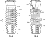
FIG. 3 illustrates a side view of an implant according to a third implementation of the present invention; -
FIG. 4 illustrates a side view of an implant according to a fourth implementation of the present invention; -
FIG. 5 illustrates a side view of an implant according to a fifth implementation of the present invention; -
FIG. 6 illustrates a side view of an abutment that is to be attached to a dental implant, such as the ones inFIGS. 1-5 , according to yet another implementation of the present invention; -
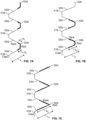
FIG. 7A illustrates a side view of the threaded portion of an implant with a flattened root according to another aspect of the present invention; -
FIG. 7B illustrates a side view of the threaded portion of an implant with a rounded root according to another aspect of the present invention; -
FIG. 7C illustrates a side view of the threaded portion of an implant with a narrower angled root according to another aspect of the present invention; -
FIG. 8A illustrates a side view of the threaded portion of an implant with a flattened crest according to another aspect of the present invention; -
FIG. 8B illustrates a side view of the threaded portion of an implant with a rounded crest according to another aspect of the present invention; -
FIG. 8C illustrates a side view of the threaded portion of an implant with a peaked crest according to another aspect of the present invention; and -
FIG. 9 is a flow diagram illustrating a method of forming an implant according to an implementation of the present invention. - While the present disclosure can be embodied in many different forms, there is shown in the drawings and will be described various exemplary aspects of the present disclosure with the understanding that the present disclosure is to be considered as an exemplification of the principles thereof and is not intended to limit the broad aspect of the present disclosure to the illustrated aspects.
-
FIG. 1 illustrates a side view of animplant 10 according to a first implementation. Theimplant 10 may, for example, be made of titanium or alloys thereof.FIGS. 2 ,3 ,4 , and5 which are discussed below, describe alternative implant designs that may also be used according to certain implementations of the disclosed subject matter. - The
implant 10 has an elongated body. The top of the elongated body includes ahead portion 12, which includes anon-rotational boss 14. In the illustrated implementation ofFIG. 1 , theboss 14 is hexagonal. Theboss 14 is configured to be engageable with a tool that screws theimplant 10 into bone tissue. Theboss 14 is also used for non-rotationally engaging a correspondingly-shaped socket on a restorative or prosthetic component (e.g., an abutment with a tooth-shaped crown attached thereto) that is attached to theimplant 10. Thehead portion 12 also includes acollar 16. - A threaded
bottom portion 20 facilitates bonding with bone or gingiva. The threadedbottom portion 20 includes athread 22 that makes a plurality of turns around theimplant 10. The turns are typically in a helical pattern, as shown inFIG. 1 . In certain implementations, the threadedbottom portion 20 may include multiple threads, so as to define a multi-lead thread. - Further, each of the turns of the
thread 22 includes a root region, a flank region and a crest region. The root region of a turn in thethread 22 is located at a minor diameter with respect to a central axis of theimplant 10, while the crest region is located at a major diameter with respect to the central axis of theimplant 10. The flank region is the surface connecting the root and the crest regions. The crest region provides primary stability for theimplant 10 by ensuring a secure mechanical connection between theimplant 10 and the bone or gingiva. Different implementations of the root, flank and crest regions will be described in detail with respect toFIGS. 7A-7C and8A-8C . The threadedbottom portion 20 may further include a self-tappingregion 24 with incremental cutting edges that allows theimplant 10 to be installed without the need for a bone tap. - The
thread 22 includes a roughenedportion 30. The roughenedportion 30 can aid in the osscointegration process by improving the integration between bone or gingiva and theimplant 10. This improved integration provides a secondary level of stability for the implant. The roughenedportion 30 may be generated using a variety of techniques including, for example, acid etching, grit blasting, or a combination thereof. As described below, the preferred roughening technique is grit blasting. As illustrated inFIG. 1 , the roughenedportion 30 is located on the root and flank regions of thethread 22, but not on the crest regions. A transition region from the roughened portion to the relatively smoother surface occurs along the thread's flank regions between the root and crest regions. In certain implementations, the transition region includes a portion of varying roughness in the direction of the crest. For example, in the implementation ofFIG. 1 , the transition region includes a portion of decreasing roughness in the direction of the crest. That is, the transition region decreases in roughness as it approaches the relatively smooth crest. Additionally, as shown inFIG. 1 , the self-tappingregion 24 of theimplant 10 is relatively smooth compared to the roughenedportion 30. - A transition point between the roughened
portion 30 and the relatively smooth surface of the crest can be chosen to minimize interference with the surface of the crest regions while maximizing osseointegration with the roughened portions on the root and flank regions. As will be described in further detail below with respect toFIGS. 7A-7C and8A-8C , different transition points can be chosen for different thread geometries. -
FIG. 2 illustrates animplant 110 that differs in physical features from theimplant 10 ofFIG. 1 to allow it to extend through the gingiva. Like the threads of theimplant 10, the threads of theimplant 110 are in a helical pattern. Theimplant 110 also includes an elongatedmiddle section 112 that is relatively smooth compared to the roughenedportion 130. Similar to the self-tappingregion 24 ofFIG. 1 , the self-tappingregion 124 illustrated inFIG. 2 is also relatively smooth compared to the roughenedportion 130. Theimplant 110 also differs from theimplant 10 in the details of the roughenedportion 130. More specifically, the roughenedportion 130 extends up a smaller portion of the flank regions of theimplant 110 compared to the roughenedportion 30 of theimplant 10 ofFIG. 1 . As described above with respect toFIG. 1 , the transition point between the roughened portion and the relatively smooth surface of theimplant 110 can be chosen to minimize interference with the cutting surface of the crest regions while maximizing osseointegration with the roughened surfaces on the root and flank regions. -
FIG. 3 illustrates a more typical trans-gingival implant 210 that differs from theimplant 10 ofFIG. 1 and theimplant 110 ofFIG. 2 in the details of the contours of the threads defining the exterior of the threadedbottom portion 220. Like theimplant 10 ofFIG. 1 and theimplant 110 ofFIG. 2 , theimplant 210 has a roughenedportion 230 which is located on the root regions and portions of the flank regions of theimplant 210. Additionally, the threads of theimplant 210 are also in a helical pattern. The threads of theimplant 210 haveportions 235 of their crests truncated, as described inU.S. Patent No. 5,902,109 , which is hereby explicitly mentioned. -
FIG. 4 illustrates animplant 310 that includes twothreadless regions regions regions FIGS. 1-3 in that the threadedregions - As shown in
FIG. 4 , thethreadless regions FIG. 1 , the roughened surfaces provide theimplant 310 with a secondary level of stability to help secure the implant after installation. Because thethreadless regions FIGS. 1-3 . Further, although the implants ofFIGS. 1-3 have smooth self-tapping regions, in certain implementations, the root and flank regions of threads in the self-tapping region may be roughened to further increase implant stability, as shown inFIG. 4 . As shown inFIG. 4 , the crests of these threaded portions in the self-tapping region remain smooth. -
FIG. 5 illustrates a trans-gingival implant 410 that differs from theimplant 10 ofFIG. 1 in the details of the configuration of thethread 412 along the exterior of the threaded bottom portion and in the inclusion of a vertical groove 414 extending up the length of theimplant 410. More specifically, thethread 412 has a larger lead compared to the leads illustrated inFIGS. 1-4 , which effectively increases the size of the root regions relative to the crest regions of thethread 412. Because the root regions of thethread 412 are larger, theimplant 410 has more of its surface roughened compared to the implants shown inFIGS. 1-4 . Additionally, as mentioned above, theimplant 410 has an extended vertical groove 414 compared to the implants ofFIGS. 1-4 . The vertical groove 414 is roughened and further improves osseointegration to theimplant 410. -
FIG. 6 illustrates anabutment 420 configured to attach to both an implant (e.g., one of the implants illustrated inFIGS. 1-5 ) and to receive a tooth-shaped crown (not shown). Theabutment 420 includes anupper portion 422 shaped to receive and securely attach to a dental crown that is typically porcelain. In other implementations, other shapes may be used for the upper portion. Theabutment 420 also includes alower portion 424, which attaches to an implant through an internal socket (not shown) that would be non-rotationally coupled to an external anti-rotational feature of the implant, such as thehexagonal boss 14 on theimplant 10 ofFIG. 1 . A screw extends through theabutment 420 and engages the internal threads within the bore of the implant to axially secure theabutment 420 on the implant, as is well known in the art. Theabutment 420 also includesthreads 426 on thelower portion 424, which are similar to the threaded portions of the implants described above with respect toFIGS. 1-5 . Specifically, thethreads 426 on theabutment 420 include roughenedsurfaces 428 in the root and flank regions of thethreads 426, while the crest regions of thethreads 426 remain relatively smooth. As illustrated inFIG. 6 , thethreads 426 on theabutment 420 are significantly smaller than the threads on the implants described above with respect toFIGS. 1-5 . Thethreads 426 and the roughenedsurfaces 428 help to promote gingival tissue attachment to the surface of theabutment 420. - As described above, implants according to the disclosed subject matter include at least one thread with portions of varying roughness. The thread can include one or more turns around the central axis of the implants, and each turn can include a root region, a flank region and a crest region. The root region of a turn in thread is located at a minor diameter with respect to the central axis of the implant while the crest region is located at a major diameter with respect to the central axis. The flank region serves as a transition region between the root and the crest regions. As shown in
FIGS. 7A-7C andFIGS. 8A-8C , in different implementations, the root, flank and crest regions can have different shapes and can extend at different angles with respect to each other. -
FIGS. 7A-7C illustrate side views of the threaded portion of various implants with differently shaped roots according to the disclosed subject matter. Each of the threaded implant portions illustrated inFIGS. 7A-7C includes at least one root, flank, and crest. The threaded portion ofFIG. 7A includescrests 510a androots 520a, each with a flattened shape, andmultiple flanks 530a connecting thecrests 510a androots 520a. Each of theflanks 530a has a length 'L1', and a segment of eachflank 530a, each segment with a length 'R1', has a roughened portion. The length of the roughened segment, R1, can be chosen based on performance requirements and the geometry of a particular implant. For example, the length R1 may be chosen to achieve an acceptable balance between the increased stability offered by the roughened portion and the increase in insertion torque required to install the implant. As shown inFIG. 7A , the roughened portion is on an inner section of each of theflanks 530a relative to a central axis of the implant (central axis not shown). Further, an outer section of each of the flanks 530a (relative to the central axis) has a surface similar to thecrests 510a, which is smoother relative to the roughened portion. - In certain implementations, the threaded portions of
FIG. 7A include transition regions from the roughened portion to the relatively smoother portions of theflanks 530a and crests 510a. The transition region can optionally include a portion of varying roughness in the direction of thecrest 510a. In other implementations, the entire roughened portion can have a similar roughness. - The threaded portion of
FIG. 7B is similar to the threaded portion illustrated inFIG. 7A , but includescurved roots 520b instead of flattened roots. Further, each of theflanks 530b has a length 'L2', and a segment of eachflank 530b has a roughened portion of length 'R2' that is longer than 'R1'. Like the roughened portions described above with respect toFIG. 7A , each roughened portion illustrated inFIG. 7B is on an inner section of each of the flanks relative to a central axis of the implant (central axis not shown), and an outer section of each of the flanks (relative to the central axis) has roughness similar to the crests. The flattened crests 510b ofFIG. 7B are similar to thecrests 510a ofFIG. 7A . - The threaded portion of
FIG. 7C is similar to the threaded portion illustrated inFIGS. 7A and 7B , but includes narrowerangled roots 520c instead of flattened or curved roots. Further, each of theflanks 530c has a length 'L3', and a segment of eachflank 530c has a roughened portion with a length 'R3'. Like the roughened portions described above with respect toFIGS. 7A and 7B , each roughened portion illustrated inFIG. 7C is on an inner section of each of the flanks relative to a central axis of the implant (central axis not shown), and an outer section of each of the flanks (relative to the central axis) has roughness similar to the crests. Thecrests 510c ofFIG. 7C are similar to thecrests 510a ofFIG. 7A and thecrests 510b ofFIG. 7B . -
FIGS. 8A-8C illustrate side views of the threaded portion of implants with differently shaped crests according to the disclosed subject matter. Each of the threaded implant portions illustrated inFIGS. 8A-8C includes at least one root, flank, and crest. Like the threaded portion ofFIG. 7A , the threaded portion ofFIG. 8A includescrests 610a androots 620a, each with a flattened shape, andmultiple flanks 630a connecting thecrests 610a androots 620a. Each of theflanks 630a in the threaded portion ofFIG. 8A has a length 'L4', and a segment of eachflank 630a has a roughened portion with a length 'R4'. As shown inFIG. 8A , the roughened portion of the implant inFIG. 8A is on an inner section of each of theflanks 630a relative to a central axis of the implant (central axis not shown). Further, an outer section of each of the flanks 630a (relative to the central axis) has roughness similar to thecrests 610a. - The threaded portion of
FIG. 8B is similar to the threaded portion illustrated inFIG. 8A , but includescurved crests 610b instead of flattened crests. Further, each of theflanks 630b has a length 'L5', and a segment of eachflank 630b has a roughened portion with a length 'R5'. Like the roughened portions described above with respect toFIG. 8A , each roughened portion illustrated inFIG. 8B is on an inner section of each of theflanks 630b relative to a central axis of the implant (central axis not shown), and an outer section of each of theflanks 630b (relative to the central axis) has roughness similar to thecrests 610b. Theroots 620b ofFIG. 8B are similar to theroots 620a of FIG.6A. - The threaded portion of
FIG. 8C is similar to the threaded portion illustrated inFIGS. 8A and 8B , but includespeaked crests 610c instead of flattened or curved crests. Further, each of theflanks 630c has a length 'L6', and a segment of eachflank 630c has a roughened portion with a length 'R6'. Like the roughened portions described above with respect toFIGS. 8A and 8B , each roughened portion illustrated inFIG. 8C is on an inner section of each of theflanks 630c relative to a central axis of the implant (central axis not shown), and an outer section of each of the flanks (relative to the central axis) has roughness similar to thecrests 610c. Theroots 620c ofFIG. 8C are similar to theroots 620a ofFIG.8A and theroots 620b ofFIG. 8B . - As shown in
FIG. 8C , anozzle 640 is placed between the root and crest regions of the threaded portion. Thenozzle 640 is used to perform grit blasting on the threaded portion and to appropriately roughen the threaded portion's surface. Optionally, thenozzle 640 can be guided by a laser or another optical or imaging device (not shown) that identifies the specific location of thenozzle 640 relative to the thread structure such that the blasting occurs between crest regions in a helical pattern along the root regions. For example, the laser or imaging device can identify and track the locations of the crests of two adjacent turns of the thread to ensure that thenozzle 640 remains substantially at the midpoint between those two adjacent crests. In an alternative implementation, a mask can be used to cover portions of the threaded portion in order to cover up areas that should not be treated or roughened. - As shown in
FIGS. 7A-7C and8A-8C , threaded implant portions as disclosed herein can have different shapes and sizes. More specifically, the flank regions connecting the root and the crest regions of the threaded portions can have different lengths and extend at different angles with respect to each other. Generally speaking the lengths of the flank regions range from 0.05 mm to 1 mm. In one preferred implementation, the length of the flank region is in the range from 0.1 mm to 0.3 mm. Further, in a preferred implementation, up to 95 percent of the flank region can be roughened. In other implementations, the roughened portion makes up about 50% of the length of the flank region, in addition to the adjacent surface at the thread's root. In an implementation requiring less roughening, the roughened portion makes up about 25% of the length of the flank region, in addition to the adjacent surface at the thread's root. Other percentages of the flank region can roughened in other implementations. - Further, although not shown in
FIGS. 7A-7C and8A-8C , it is understood that the roughened portions of threads according to the disclosed subject matter can be asymmetrical. That is, opposing flanks within a single turn of a thread can have roughened portions with different lengths. Additionally, the lengths of roughened portions within a thread can generally increase or decrease in a direction moving from the bottom of the thread towards the top of the thread. Portions of the implant that integrate with dense cortical bone can have increased roughness compared to portions of the implant that integrate with softer cancellous bone. - As would be understood by one of ordinary skill in the art, elements of the implementations in
FIGS. 7A-7C andFIGS. 8A-8C may be combined with each other in accordance with the described subject matter. For example, different crest and root shapes as disclosed herein may be combined with each other as appropriate to form threads for implants as appropriate. Further, crest and root shapes other than those depicted inFIGS. 7A-7C andFIGS. 8A-8C may be incorporated in certain implementations of the disclosed subject matter. Similarly, flank shapes other than those depicted inFIGS. 7A-7C andFIGS. 8A-8C may be incorporated in other implementations of the disclosed subject matter. For example, certain implementations may incorporate convex flanks, concave flanks, wavelike flanks, or any other appropriate flank shape. -
FIG. 9 is a flow diagram illustrating a method of forming an implant according to the disclosed subject matter. Atstep 700, an implant having a threaded outer surface is provided. Each thread includes at least one turn around the implant, and each turn has at least one root, one flank, and one crest. According to certain implementations, the implant is comprised of titanium, a titanium alloy, or the like. Atstep 701, the outer surface of the implant is treated such that only the root and a portion of the flank are roughened while the crest remains untreated. In certain implementations, the crest may be lightly treated compared to the root and the portion of the flank. For example, in certain implementations, the crest may be lightly acid etched while the root and the portion of the flank are more heavily acid etched. Optionally, only a portion of the length of the implant may be treated such that only some of the turns of the threads have roughened portions at their root regions. For example, according to certain implementations, only a fraction of the turns (e.g., one half of the turns) of the threaded outer surface may be treated along the lower portion of the implant, while the remainder of the threaded outer surface remains untreated. - Treating the outer surface at
step 701 may include blasting the outer surface. The blasting can optionally be performed using a blast nozzle. When a blast nozzle is used to treat the outer surface, the blast nozzle can be inserted in between adjacent crests of the implant in order to treat only the desired region or regions. Further, in certain implementations, the blasting may be performed along a helical locus of the outer surface. According to certain implementations, other treatment methods may be used. For example, in certain implementations, the surface may be acid etched to create a roughened surface on the desired roots and/or flanks of the implant's outer surface. - The blast nozzle can blast different types of materials, and the different types of materials can have different particle sizes to produce different roughnesses on the outer surface of the implant. For example, in one implementation, calcium phosphate particles can be used as a blast material to treat the outer surface of an implant. The calcium phosphate particles can range in size, for example, from 150-425 microns. In addition to material types and particle sizes, other variables such as, for example, particle shape, particle hardness, particle flow rate, the size of the blast nozzle, the distance between the blast nozzle and the surface of the implant, the angle at which the nozzle is placed, and the type of gas used to accelerate the blasted materials can affect the roughness of the implant's outer surface.
- After the outer surface is treated at
step 701, the outer surface of the implant can undergo a second optional treatment atstep 702. The further treatment can include treatment of the crest, flank and root regions with an acid etching treatment, which provides the outer surface of the implant with additional roughness. For example, in implementations where the implant is made of commercially pure titanium, a mixture including both hydrochloric acid and sulfuric acid may be used to perform acid etching, as described inU.S. Patent No. 7,857,987 , which is hereby explicitly mentioned. - In implementations where the implant is made of titanium alloy, a mixture including both hydrochloric acid and hydrofluoric acid can be used to perform acid etching, as described in
U.S. Patent No. 8,251,700 , which is hereby also mentioned. - After a surface has been blasted at
step 701 and acid etched atstep 702, the entire threaded region has some roughness, with the crest regions remaining relatively smooth compared to the root regions and portions of the flank regions. For example, in certain implementations, the surface roughness, Ra, can be in the range of 0.7-1.6 microns along the root regions and flank regions that have been both grit-blasted and acid-etched, while the surface roughness, Ra, can be in the range of 0.3-0.7 microns along the crest regions that have been only acid-etched. In one particular implementation, the surface roughness, Ra, is about 1.3 microns along the root regions and flank regions that have been both grit blasted and acid etched, while the surface roughness, Ra, is about 0.5 microns along the crest regions that have been only acid etched. The surface roughness is preferably measured via the inverse Fourier transform (IFFT) method. - While particular implementations and applications of the present disclosure have been illustrated and described, it is to be understood that the invention is not limited to the precise construction and compositions disclosed herein and that various modifications, changes, and variations can be apparent from the foregoing descriptions without departing from the scope of the invention as defined in the appended claims.
Claims (14)
- An implant (10) for implantation into bone tissue having an exterior surface comprising:an elongated body having an upper portion (112) configured to receive a prosthesis, a lower portion (120) for being submerged in said bone tissue and an outer surface; andat least one thread on the outer surface making a plurality of turns around the elongated body between the lower portion and the upper portion, the at least one thread including a root, a flank, and a crest,characterized in that the root and a segment of the flank have an acid etched surface so that the root and a segment of the flank have a roughened portion relative to the crest.
- The implant of claim 1 wherein the crest is lightly acid etched while the root and the segment of the flank are more heavily acid etched.
- The implant of claim 1 or claim 2, wherein the outer surface of the implant is first grit blasted and then acid etched, the acid etched surface of the crest having a surface roughness of 0.3 to 0.7 microns.
- The implant of claim 1, where an inner section of the flank relative to a central axis of the implant has the roughened portion relative to the crest while an outer section of the flank relative to the central axis has roughness similar to the crest.
- The implant of claim 1, further comprising a self-tapping region.
- The implant of claim 6, wherein the self-tapping region is smooth relative to the roughened portion of the root and the roughened portion of the flank.
- The implant of claim 1, wherein the outer surface of the implant is first grit biased and then acid etched, and the crest is relatively smooth compared to the roughened portion of the root and a segment of the flank.
- The implant of claim 1, wherein the crest has a flattened shape or wherein the crest has a rounded shape.
- The implant of claim 1, wherein the crest has a peaked shape.
- The implant of claim 1, wherein the root has a flattened shape.
- The implant of claim 1, wherein the root has a rounded shape or wherein the root has a narrow-angled shape.
- The implant of any preceding claim wherein the implant is comprised of titanium, a titanium alloy, or the like.
- A method of forming an implant having a threaded outer surface including a root, a flank and a crest, characterized in that the method comprises: treating the threaded outer surface by acid etching at only the root and a portion of the flank such that only the root and the portion of the flank are roughened while the crest remains untreated.
- A method of claim 13 wherein the method further comprises:
acid etching the crest such that the acid etched crest has a surface roughness less than the acid etched root and the portion of the flank.
Applications Claiming Priority (3)
| Application Number | Priority Date | Filing Date | Title |
|---|---|---|---|
| US201461978731P | 2014-04-11 | 2014-04-11 | |
| PCT/US2015/025057 WO2015157495A1 (en) | 2014-04-11 | 2015-04-09 | Implant with high primary stability and accelerated secondary stability |
| EP15776219.6A EP3128988B1 (en) | 2014-04-11 | 2015-04-09 | Implant with high primary stability and accelerated secondary stability |
Related Parent Applications (1)
| Application Number | Title | Priority Date | Filing Date |
|---|---|---|---|
| EP15776219.6A Division EP3128988B1 (en) | 2014-04-11 | 2015-04-09 | Implant with high primary stability and accelerated secondary stability |
Publications (2)
| Publication Number | Publication Date |
|---|---|
| EP3777753A1 EP3777753A1 (en) | 2021-02-17 |
| EP3777753B1 true EP3777753B1 (en) | 2024-05-22 |
Family
ID=54264095
Family Applications (2)
| Application Number | Title | Priority Date | Filing Date |
|---|---|---|---|
| EP15776219.6A Active EP3128988B1 (en) | 2014-04-11 | 2015-04-09 | Implant with high primary stability and accelerated secondary stability |
| EP19218309.3A Active EP3777753B1 (en) | 2014-04-11 | 2015-04-09 | Implant with high primary stability and accelerated secondary stability |
Family Applications Before (1)
| Application Number | Title | Priority Date | Filing Date |
|---|---|---|---|
| EP15776219.6A Active EP3128988B1 (en) | 2014-04-11 | 2015-04-09 | Implant with high primary stability and accelerated secondary stability |
Country Status (5)
| Country | Link |
|---|---|
| US (3) | US10414022B2 (en) |
| EP (2) | EP3128988B1 (en) |
| CN (1) | CN106535860B (en) |
| ES (1) | ES2982537T3 (en) |
| WO (1) | WO2015157495A1 (en) |
Families Citing this family (7)
| Publication number | Priority date | Publication date | Assignee | Title |
|---|---|---|---|---|
| EP3034033A1 (en) | 2014-12-16 | 2016-06-22 | Nobel Biocare Services AG | Dental implant |
| ES2842303T3 (en) * | 2015-08-11 | 2021-07-13 | Biomet 3I Llc | Dental implant that has a conical threaded surface with installation enhancement characteristics |
| JP6642135B2 (en) * | 2016-03-09 | 2020-02-05 | 株式会社リコー | Dental prosthesis, method for manufacturing dental prosthesis, and apparatus for manufacturing dental prosthesis |
| EP4331530B1 (en) | 2018-11-12 | 2025-07-02 | Nobel Biocare Services AG | Method of forming a protective layer on the surface of an implantable component, implantable component with the protective layer and use of the protective layer |
| EP3747394A1 (en) * | 2019-06-04 | 2020-12-09 | VITA-ZAHNFABRIK H. Rauter GmbH & Co. KG | Dental implant with different surface rawness |
| US11786343B2 (en) | 2020-07-09 | 2023-10-17 | Southern Implants (Pty) Ltd | Dental implants with stepped threads and systems and methods for making the same |
| BR202020017123U2 (en) * | 2020-08-21 | 2022-03-03 | Carlos Aurélio Andreucci | CONSTRUCTION PROVISION APPLIED IN SCREW FOR BONE IMPLANT |
Family Cites Families (92)
| Publication number | Priority date | Publication date | Assignee | Title |
|---|---|---|---|---|
| US5360448A (en) * | 1991-10-07 | 1994-11-01 | Thramann Jeffrey J | Porous-coated bone screw for securing prosthesis |
| CA2093900C (en) * | 1993-04-13 | 1996-12-10 | Norman H. K. Kwan | Dental implant having cutting means |
| JPH06304186A (en) * | 1993-04-21 | 1994-11-01 | Nikon Corp | Intraosseous implant |
| US5571017A (en) | 1994-10-05 | 1996-11-05 | Core-Vent Corporation | Selective surface, externally-threaded endosseous dental implant |
| US5863201A (en) | 1994-11-30 | 1999-01-26 | Implant Innovations, Inc. | Infection-blocking dental implant |
| WO1996016611A1 (en) | 1994-11-30 | 1996-06-06 | Implant Innovations, Inc. | Implant surface preparation |
| US6491723B1 (en) | 1996-02-27 | 2002-12-10 | Implant Innovations, Inc. | Implant surface preparation method |
| US6652765B1 (en) * | 1994-11-30 | 2003-11-25 | Implant Innovations, Inc. | Implant surface preparation |
| US5782919A (en) | 1995-03-27 | 1998-07-21 | Sdgi Holdings, Inc. | Interbody fusion device and method for restoration of normal spinal anatomy |
| FR2734707B1 (en) | 1995-05-30 | 1997-08-29 | Guedj Leon | DENTAL IMPLANTOLOGY SURGICAL EQUIPMENT AND ELEMENTS, DENTAL IMPLANT AND DRILLING INSTRUMENTS, COMPONENTS |
| US5727943A (en) | 1995-07-18 | 1998-03-17 | Implant Innovations, Inc. | Self-tapping, screw-type dental implant |
| SE505112C2 (en) | 1995-10-31 | 1997-06-30 | Idea Ab | Plug for skull bone |
| DE69535892D1 (en) | 1995-12-08 | 2009-01-08 | Zimmer Dental Inc | DENTAL IMPLANT WITH MULTIPLE STRUCTURED SURFACE |
| JP3881025B2 (en) | 1996-01-18 | 2007-02-14 | インプラント・イノヴェーションズ・インコーポレーテッド | Low friction screw dental implant |
| US5829978A (en) * | 1997-11-10 | 1998-11-03 | Sulzer Calcitek Inc. | Surface roughening of self-tapping dental implants |
| US6048204A (en) | 1998-02-03 | 2000-04-11 | Lifecore Biomedical, Inc. | Self tapping screw type dental implant |
| US6117249A (en) | 1998-02-13 | 2000-09-12 | Kerk Motion Products, Inc. | Treating metallic machine parts |
| US5885079A (en) | 1998-06-22 | 1999-03-23 | Core-Vent Corporation | Selective surface, endosseous dental implants |
| SE9802571D0 (en) | 1998-07-17 | 1998-07-17 | Astra Ab | Implant |
| US6402516B2 (en) | 1999-11-10 | 2002-06-11 | Stefan Ihde | Jaw implant |
| US6991463B2 (en) | 1998-11-11 | 2006-01-31 | Stefan Ihde | Dental implant and method of insertion |
| US6102703A (en) | 1999-02-15 | 2000-08-15 | Sulzer Calcitek Inc. | Self-tapping dental implant having a bio-reactive coating |
| US6095817A (en) | 1999-02-24 | 2000-08-01 | Sulzer Calcitek Inc. | Dental implant having multiple textured surfaces |
| US6287117B1 (en) | 1999-04-22 | 2001-09-11 | Sulzer Dental Inc. | Endosseous dental implants including a healing screw and an optional implant extender |
| EP1223886A4 (en) | 1999-10-14 | 2006-07-05 | Robert L Schroering | Dental implant having a dual-textured exterior surface |
| US6379154B2 (en) | 1999-10-19 | 2002-04-30 | John Devincenzo | Subperiosteal bone anchor |
| US7048541B2 (en) | 2000-04-04 | 2006-05-23 | Nobel Biocare Ab | Implant having attachment and hole-insert parts, and method for producing such an implant |
| SE517066C2 (en) * | 2000-04-04 | 2002-04-09 | Nobel Biocare Ab | Implants showing connection and puncture insertion parts and the procedure for such implants |
| SE516282C2 (en) * | 2000-04-04 | 2001-12-10 | Nobel Biocare Ab | Implants provided with connection and hole insertion parts and the procedure for such implants |
| US6419492B1 (en) | 2000-05-15 | 2002-07-16 | Robert L. Schroering | Dental implant system incorporating an external hex and Morse tapered walls |
| US20060078847A1 (en) | 2000-09-29 | 2006-04-13 | Kwan Norman H | Dental implant system and additional methods of attachment |
| US6626671B2 (en) * | 2000-10-11 | 2003-09-30 | Lifecore Biomedical, Inc. | Method of manufacturing cutting flutes on a coated or roughened dental implant |
| US6386876B1 (en) | 2000-11-29 | 2002-05-14 | Kenneth K. S. Lee | Universal tissue emergence profile shaping healing abutment, provisional and restoration abutments, impression coping and ceramic crown base system |
| US6599322B1 (en) | 2001-01-25 | 2003-07-29 | Tecomet, Inc. | Method for producing undercut micro recesses in a surface, a surgical implant made thereby, and method for fixing an implant to bone |
| US7018418B2 (en) | 2001-01-25 | 2006-03-28 | Tecomet, Inc. | Textured surface having undercut micro recesses in a surface |
| US6620332B2 (en) | 2001-01-25 | 2003-09-16 | Tecomet, Inc. | Method for making a mesh-and-plate surgical implant |
| SE0102749D0 (en) | 2001-08-15 | 2001-08-15 | Astra Tech Ab | Implant, arrangement including an implant, and method of inserting said implant into bone tissue |
| JP2005538745A (en) | 2001-12-06 | 2005-12-22 | スミス アンド ネフュー インコーポレーテッド | In-situ oxidized textured surface for prosthetic devices and method of manufacturing the same |
| SE520756C2 (en) * | 2001-12-21 | 2003-08-19 | Nobel Biocare Ab | Method of providing surface structure on implants as well as such implants |
| SE523395C2 (en) | 2001-12-21 | 2004-04-13 | Nobel Biocare Ab | Implants and methods and systems for providing such implants |
| WO2003084426A1 (en) | 2002-04-04 | 2003-10-16 | Akira Kitamura | Drill device for implanting |
| US7338493B1 (en) | 2002-06-28 | 2008-03-04 | Biomet Manufacturing Corp. | Method and apparatus for cementing a screw anchor |
| US7341453B2 (en) | 2002-11-01 | 2008-03-11 | Coatoam Gary W | Dental implant method and apparatus |
| KR100487132B1 (en) * | 2003-03-26 | 2005-05-03 | 설영택 | Helical implant |
| US8651863B2 (en) | 2003-04-01 | 2014-02-18 | Robert Schroering | Band of connective tissue grooves for use with a dental implant or a separate abutment for a dental implant |
| EP1601301A1 (en) * | 2003-05-03 | 2005-12-07 | Wolfgang Dinkelacker | Bone implant that can be screwed in |
| US8251700B2 (en) | 2003-05-16 | 2012-08-28 | Biomet 3I, Llc | Surface treatment process for implants made of titanium alloy |
| IL156033A0 (en) | 2003-05-21 | 2004-03-28 | Ophir Fromovich Ophir Fromovic | Dental implant |
| FR2858209B1 (en) | 2003-07-30 | 2006-06-02 | Depuy France | ACETABULAR IMPLANT AND METHOD OF MANUFACTURING THE IMPLANT |
| US7250055B1 (en) | 2003-08-26 | 2007-07-31 | Biomet Manufacturing Corp. | Method and apparatus for cement delivering buttress pin |
| ATE404228T1 (en) | 2003-10-27 | 2008-08-15 | Straumann Holding Ag | IMPLANT WITH A CERAMIC COATING |
| US7845945B2 (en) | 2004-01-28 | 2010-12-07 | Stanton R. Canter | Anchoring element for use in bone |
| SE0400546D0 (en) | 2004-03-05 | 2004-03-05 | Dan Lundgren | Tubular bone anchoring element |
| USD583057S1 (en) | 2004-03-29 | 2008-12-16 | Gc Corporation | Dental implant fixture |
| US7473278B2 (en) | 2004-09-16 | 2009-01-06 | Smith & Nephew, Inc. | Method of surface oxidizing zirconium and zirconium alloys and resulting product |
| US7699613B2 (en) | 2005-02-11 | 2010-04-20 | Niznick Gerald A | One-piece, screw-receiving, externally-threaded endosseous dental implants and related transfer components, comfort caps and abutments |
| WO2006091582A2 (en) | 2005-02-24 | 2006-08-31 | Implant Innovations, Inc. | Surface treatment methods for implants made of titanium or titanium alloy |
| US8617248B2 (en) | 2005-05-06 | 2013-12-31 | Titan Spine, Llc | Spinal implant having variable ratios of the integration surface area to the axial passage area |
| US8591590B2 (en) | 2005-05-06 | 2013-11-26 | Titan Spine, Llc | Spinal implant having a transverse aperture |
| US8262737B2 (en) | 2005-05-06 | 2012-09-11 | Titan Spine, Llc | Composite interbody spinal implant having openings of predetermined size and shape |
| US8585766B2 (en) | 2005-05-06 | 2013-11-19 | Titan Spine, Llc | Endplate-preserving spinal implant with an integration plate having durable connectors |
| US8585767B2 (en) | 2005-05-06 | 2013-11-19 | Titan Spine, Llc | Endplate-preserving spinal implant with an integration plate having durable connectors |
| US8480749B2 (en) | 2005-05-06 | 2013-07-09 | Titan Spine, Llc | Friction fit and vertebral endplate-preserving spinal implant |
| US8992622B2 (en) | 2005-05-06 | 2015-03-31 | Titan Spine, Llc | Interbody spinal implant having a roughened surface topography |
| US8562685B2 (en) | 2005-05-06 | 2013-10-22 | Titan Spine, Llc | Spinal implant and integration plate for optimizing vertebral endplate contact load-bearing edges |
| US8545568B2 (en) | 2005-05-06 | 2013-10-01 | Titan Spine, Llc | Method of using instruments and interbody spinal implants to enhance distraction |
| US8562684B2 (en) | 2005-05-06 | 2013-10-22 | Titan Spine, Llc | Endplate-preserving spinal implant with an integration plate having a roughened surface topography |
| US8758443B2 (en) | 2005-05-06 | 2014-06-24 | Titan Spine, Llc | Implants with integration surfaces having regular repeating surface patterns |
| US8758442B2 (en) | 2005-05-06 | 2014-06-24 | Titan Spine, Llc | Composite implants having integration surfaces composed of a regular repeating pattern |
| US8585765B2 (en) | 2005-05-06 | 2013-11-19 | Titan Spine, Llc | Endplate-preserving spinal implant having a raised expulsion-resistant edge |
| US8435302B2 (en) | 2005-05-06 | 2013-05-07 | Titan Spine, Llc | Instruments and interbody spinal implants enhancing disc space distraction |
| US8814939B2 (en) | 2005-05-06 | 2014-08-26 | Titan Spine, Llc | Implants having three distinct surfaces |
| US8403991B2 (en) | 2005-05-06 | 2013-03-26 | Titan Spine Llc | Implant with critical ratio of load bearing surface area to central opening area |
| US8551176B2 (en) | 2005-05-06 | 2013-10-08 | Titan Spine, Llc | Spinal implant having a passage for enhancing contact between bone graft material and cortical endplate bone |
| ES2368818T3 (en) | 2006-02-28 | 2011-11-22 | Straumann Holding Ag | PILLAR WITH HYDROXYLATED SURFACE. |
| US8469710B2 (en) | 2006-08-01 | 2013-06-25 | Vitali Bondar | Dental implant system and method |
| USD595850S1 (en) | 2007-02-09 | 2009-07-07 | Gebr. Brasseler Gmbh & Co. Kg | Dental instrument |
| US8038442B2 (en) | 2007-04-23 | 2011-10-18 | Nobel Biocare Services Ag | Dental implant and dental component connection |
| US7806693B2 (en) | 2007-04-23 | 2010-10-05 | Nobel Biocare Services Ag | Dental implant |
| US8221119B1 (en) * | 2007-10-09 | 2012-07-17 | Maurice Valen | Dental implant and method of installing the same |
| ES2545781T3 (en) | 2008-01-28 | 2015-09-15 | Biomet 3I, Llc | Superficial implant with greater hydrophilicity |
| CN201223459Y (en) * | 2008-07-14 | 2009-04-22 | 张正宜 | Dental implant |
| US8361381B2 (en) | 2008-09-25 | 2013-01-29 | Smith & Nephew, Inc. | Medical implants having a porous coated surface |
| CN101773413A (en) * | 2009-01-09 | 2010-07-14 | 沈阳天贺新材料开发有限公司 | Preparation method of titanium dental implant |
| US8337205B2 (en) | 2009-06-22 | 2012-12-25 | Nspired Ideas | Dental implant with interlocking and centering threads |
| US8641418B2 (en) | 2010-03-29 | 2014-02-04 | Biomet 3I, Llc | Titanium nano-scale etching on an implant surface |
| JP5714321B2 (en) * | 2010-12-25 | 2015-05-07 | 株式会社三明製作所 | Bone screw and bone screw manufacturing method |
| US8382477B2 (en) | 2011-04-18 | 2013-02-26 | Terry B. Philibin | Healing abutment system for bone contouring |
| US8992619B2 (en) | 2011-11-01 | 2015-03-31 | Titan Spine, Llc | Microstructured implant surfaces |
| WO2013142118A1 (en) | 2012-03-20 | 2013-09-26 | Biomet 3I, Llc | Surface treatment for an implant surface |
| CN103252728B (en) * | 2013-04-28 | 2015-05-20 | 陈贤帅 | A device for dental implant surface sand blasting |
| EP4331530B1 (en) * | 2018-11-12 | 2025-07-02 | Nobel Biocare Services AG | Method of forming a protective layer on the surface of an implantable component, implantable component with the protective layer and use of the protective layer |
-
2015
- 2015-04-09 EP EP15776219.6A patent/EP3128988B1/en active Active
- 2015-04-09 ES ES19218309T patent/ES2982537T3/en active Active
- 2015-04-09 CN CN201580029763.1A patent/CN106535860B/en not_active Expired - Fee Related
- 2015-04-09 EP EP19218309.3A patent/EP3777753B1/en active Active
- 2015-04-09 US US14/682,826 patent/US10414022B2/en active Active
- 2015-04-09 WO PCT/US2015/025057 patent/WO2015157495A1/en not_active Ceased
-
2019
- 2019-07-05 US US16/503,762 patent/US20190329378A1/en not_active Abandoned
-
2023
- 2023-08-14 US US18/233,643 patent/US20230398657A1/en active Pending
Also Published As
| Publication number | Publication date |
|---|---|
| EP3128988B1 (en) | 2019-12-25 |
| US20150289951A1 (en) | 2015-10-15 |
| CN106535860B (en) | 2020-01-07 |
| ES2982537T3 (en) | 2024-10-16 |
| EP3777753A1 (en) | 2021-02-17 |
| US20230398657A1 (en) | 2023-12-14 |
| US20190329378A1 (en) | 2019-10-31 |
| WO2015157495A1 (en) | 2015-10-15 |
| EP3128988A4 (en) | 2017-11-22 |
| EP3128988A1 (en) | 2017-02-15 |
| CN106535860A (en) | 2017-03-22 |
| US10414022B2 (en) | 2019-09-17 |
Similar Documents
| Publication | Publication Date | Title |
|---|---|---|
| US20230398657A1 (en) | Implant with high primary stability and accelerated secondary stability | |
| EP2278935B1 (en) | Asymmetrical dental implant | |
| US6626671B2 (en) | Method of manufacturing cutting flutes on a coated or roughened dental implant | |
| CA2832385C (en) | A fixture, a thread maker and a fixture set | |
| JP5762429B2 (en) | High torque dental implant system | |
| US20110081626A1 (en) | Dental implant | |
| US20060223030A1 (en) | Helical dental implant | |
| US9226804B2 (en) | Fixture and a fixture set and a method | |
| WO2012059908A1 (en) | Multi-threaded dental implant | |
| EP1952780A1 (en) | Dental implant | |
| US5829978A (en) | Surface roughening of self-tapping dental implants | |
| US20250318910A1 (en) | Dental implant with improved thread design | |
| WO2025229696A1 (en) | A dental implant with a gradual change in thread morphology | |
| Implant | Implant Surfaces |
Legal Events
| Date | Code | Title | Description |
|---|---|---|---|
| PUAI | Public reference made under article 153(3) epc to a published international application that has entered the european phase |
Free format text: ORIGINAL CODE: 0009012 |
|
| STAA | Information on the status of an ep patent application or granted ep patent |
Free format text: STATUS: THE APPLICATION HAS BEEN PUBLISHED |
|
| AC | Divisional application: reference to earlier application |
Ref document number: 3128988 Country of ref document: EP Kind code of ref document: P |
|
| AK | Designated contracting states |
Kind code of ref document: A1 Designated state(s): AL AT BE BG CH CY CZ DE DK EE ES FI FR GB GR HR HU IE IS IT LI LT LU LV MC MK MT NL NO PL PT RO RS SE SI SK SM TR |
|
| STAA | Information on the status of an ep patent application or granted ep patent |
Free format text: STATUS: REQUEST FOR EXAMINATION WAS MADE |
|
| 17P | Request for examination filed |
Effective date: 20210817 |
|
| RBV | Designated contracting states (corrected) |
Designated state(s): AL AT BE BG CH CY CZ DE DK EE ES FI FR GB GR HR HU IE IS IT LI LT LU LV MC MK MT NL NO PL PT RO RS SE SI SK SM TR |
|
| P01 | Opt-out of the competence of the unified patent court (upc) registered |
Effective date: 20230526 |
|
| GRAP | Despatch of communication of intention to grant a patent |
Free format text: ORIGINAL CODE: EPIDOSNIGR1 |
|
| STAA | Information on the status of an ep patent application or granted ep patent |
Free format text: STATUS: GRANT OF PATENT IS INTENDED |
|
| RIC1 | Information provided on ipc code assigned before grant |
Ipc: A61C 8/00 20060101AFI20231127BHEP |
|
| INTG | Intention to grant announced |
Effective date: 20231212 |
|
| GRAS | Grant fee paid |
Free format text: ORIGINAL CODE: EPIDOSNIGR3 |
|
| GRAA | (expected) grant |
Free format text: ORIGINAL CODE: 0009210 |
|
| STAA | Information on the status of an ep patent application or granted ep patent |
Free format text: STATUS: THE PATENT HAS BEEN GRANTED |
|
| AC | Divisional application: reference to earlier application |
Ref document number: 3128988 Country of ref document: EP Kind code of ref document: P |
|
| AK | Designated contracting states |
Kind code of ref document: B1 Designated state(s): AL AT BE BG CH CY CZ DE DK EE ES FI FR GB GR HR HU IE IS IT LI LT LU LV MC MK MT NL NO PL PT RO RS SE SI SK SM TR |
|
| REG | Reference to a national code |
Ref country code: GB Ref legal event code: FG4D |
|
| REG | Reference to a national code |
Ref country code: CH Ref legal event code: EP |
|
| REG | Reference to a national code |
Ref country code: DE Ref legal event code: R096 Ref document number: 602015088810 Country of ref document: DE |
|
| REG | Reference to a national code |
Ref country code: IE Ref legal event code: FG4D |
|
| REG | Reference to a national code |
Ref country code: LT Ref legal event code: MG9D |
|
| REG | Reference to a national code |
Ref country code: NL Ref legal event code: MP Effective date: 20240522 |
|
| PG25 | Lapsed in a contracting state [announced via postgrant information from national office to epo] |
Ref country code: IS Free format text: LAPSE BECAUSE OF FAILURE TO SUBMIT A TRANSLATION OF THE DESCRIPTION OR TO PAY THE FEE WITHIN THE PRESCRIBED TIME-LIMIT Effective date: 20240922 |
|
| PG25 | Lapsed in a contracting state [announced via postgrant information from national office to epo] |
Ref country code: BG Free format text: LAPSE BECAUSE OF FAILURE TO SUBMIT A TRANSLATION OF THE DESCRIPTION OR TO PAY THE FEE WITHIN THE PRESCRIBED TIME-LIMIT Effective date: 20240522 |
|
| PG25 | Lapsed in a contracting state [announced via postgrant information from national office to epo] |
Ref country code: HR Free format text: LAPSE BECAUSE OF FAILURE TO SUBMIT A TRANSLATION OF THE DESCRIPTION OR TO PAY THE FEE WITHIN THE PRESCRIBED TIME-LIMIT Effective date: 20240522 Ref country code: FI Free format text: LAPSE BECAUSE OF FAILURE TO SUBMIT A TRANSLATION OF THE DESCRIPTION OR TO PAY THE FEE WITHIN THE PRESCRIBED TIME-LIMIT Effective date: 20240522 |
|
| PG25 | Lapsed in a contracting state [announced via postgrant information from national office to epo] |
Ref country code: GR Free format text: LAPSE BECAUSE OF FAILURE TO SUBMIT A TRANSLATION OF THE DESCRIPTION OR TO PAY THE FEE WITHIN THE PRESCRIBED TIME-LIMIT Effective date: 20240823 |
|
| PG25 | Lapsed in a contracting state [announced via postgrant information from national office to epo] |
Ref country code: PT Free format text: LAPSE BECAUSE OF FAILURE TO SUBMIT A TRANSLATION OF THE DESCRIPTION OR TO PAY THE FEE WITHIN THE PRESCRIBED TIME-LIMIT Effective date: 20240923 |
|
| REG | Reference to a national code |
Ref country code: AT Ref legal event code: MK05 Ref document number: 1688166 Country of ref document: AT Kind code of ref document: T Effective date: 20240522 |
|
| REG | Reference to a national code |
Ref country code: ES Ref legal event code: FG2A Ref document number: 2982537 Country of ref document: ES Kind code of ref document: T3 Effective date: 20241016 |
|
| PG25 | Lapsed in a contracting state [announced via postgrant information from national office to epo] |
Ref country code: NL Free format text: LAPSE BECAUSE OF FAILURE TO SUBMIT A TRANSLATION OF THE DESCRIPTION OR TO PAY THE FEE WITHIN THE PRESCRIBED TIME-LIMIT Effective date: 20240522 |
|
| PG25 | Lapsed in a contracting state [announced via postgrant information from national office to epo] |
Ref country code: AT Free format text: LAPSE BECAUSE OF FAILURE TO SUBMIT A TRANSLATION OF THE DESCRIPTION OR TO PAY THE FEE WITHIN THE PRESCRIBED TIME-LIMIT Effective date: 20240522 |
|
| PG25 | Lapsed in a contracting state [announced via postgrant information from national office to epo] |
Ref country code: PL Free format text: LAPSE BECAUSE OF FAILURE TO SUBMIT A TRANSLATION OF THE DESCRIPTION OR TO PAY THE FEE WITHIN THE PRESCRIBED TIME-LIMIT Effective date: 20240522 |
|
| PG25 | Lapsed in a contracting state [announced via postgrant information from national office to epo] |
Ref country code: LV Free format text: LAPSE BECAUSE OF FAILURE TO SUBMIT A TRANSLATION OF THE DESCRIPTION OR TO PAY THE FEE WITHIN THE PRESCRIBED TIME-LIMIT Effective date: 20240522 |
|
| PG25 | Lapsed in a contracting state [announced via postgrant information from national office to epo] |
Ref country code: PT Free format text: LAPSE BECAUSE OF FAILURE TO SUBMIT A TRANSLATION OF THE DESCRIPTION OR TO PAY THE FEE WITHIN THE PRESCRIBED TIME-LIMIT Effective date: 20240923 Ref country code: PL Free format text: LAPSE BECAUSE OF FAILURE TO SUBMIT A TRANSLATION OF THE DESCRIPTION OR TO PAY THE FEE WITHIN THE PRESCRIBED TIME-LIMIT Effective date: 20240522 Ref country code: NO Free format text: LAPSE BECAUSE OF FAILURE TO SUBMIT A TRANSLATION OF THE DESCRIPTION OR TO PAY THE FEE WITHIN THE PRESCRIBED TIME-LIMIT Effective date: 20240822 Ref country code: NL Free format text: LAPSE BECAUSE OF FAILURE TO SUBMIT A TRANSLATION OF THE DESCRIPTION OR TO PAY THE FEE WITHIN THE PRESCRIBED TIME-LIMIT Effective date: 20240522 Ref country code: LV Free format text: LAPSE BECAUSE OF FAILURE TO SUBMIT A TRANSLATION OF THE DESCRIPTION OR TO PAY THE FEE WITHIN THE PRESCRIBED TIME-LIMIT Effective date: 20240522 Ref country code: IS Free format text: LAPSE BECAUSE OF FAILURE TO SUBMIT A TRANSLATION OF THE DESCRIPTION OR TO PAY THE FEE WITHIN THE PRESCRIBED TIME-LIMIT Effective date: 20240922 Ref country code: HR Free format text: LAPSE BECAUSE OF FAILURE TO SUBMIT A TRANSLATION OF THE DESCRIPTION OR TO PAY THE FEE WITHIN THE PRESCRIBED TIME-LIMIT Effective date: 20240522 Ref country code: GR Free format text: LAPSE BECAUSE OF FAILURE TO SUBMIT A TRANSLATION OF THE DESCRIPTION OR TO PAY THE FEE WITHIN THE PRESCRIBED TIME-LIMIT Effective date: 20240823 Ref country code: FI Free format text: LAPSE BECAUSE OF FAILURE TO SUBMIT A TRANSLATION OF THE DESCRIPTION OR TO PAY THE FEE WITHIN THE PRESCRIBED TIME-LIMIT Effective date: 20240522 Ref country code: BG Free format text: LAPSE BECAUSE OF FAILURE TO SUBMIT A TRANSLATION OF THE DESCRIPTION OR TO PAY THE FEE WITHIN THE PRESCRIBED TIME-LIMIT Effective date: 20240522 Ref country code: AT Free format text: LAPSE BECAUSE OF FAILURE TO SUBMIT A TRANSLATION OF THE DESCRIPTION OR TO PAY THE FEE WITHIN THE PRESCRIBED TIME-LIMIT Effective date: 20240522 Ref country code: RS Free format text: LAPSE BECAUSE OF FAILURE TO SUBMIT A TRANSLATION OF THE DESCRIPTION OR TO PAY THE FEE WITHIN THE PRESCRIBED TIME-LIMIT Effective date: 20240822 |
|
| PG25 | Lapsed in a contracting state [announced via postgrant information from national office to epo] |
Ref country code: DK Free format text: LAPSE BECAUSE OF FAILURE TO SUBMIT A TRANSLATION OF THE DESCRIPTION OR TO PAY THE FEE WITHIN THE PRESCRIBED TIME-LIMIT Effective date: 20240522 |
|
| PG25 | Lapsed in a contracting state [announced via postgrant information from national office to epo] |
Ref country code: EE Free format text: LAPSE BECAUSE OF FAILURE TO SUBMIT A TRANSLATION OF THE DESCRIPTION OR TO PAY THE FEE WITHIN THE PRESCRIBED TIME-LIMIT Effective date: 20240522 |
|
| PG25 | Lapsed in a contracting state [announced via postgrant information from national office to epo] |
Ref country code: CZ Free format text: LAPSE BECAUSE OF FAILURE TO SUBMIT A TRANSLATION OF THE DESCRIPTION OR TO PAY THE FEE WITHIN THE PRESCRIBED TIME-LIMIT Effective date: 20240522 |
|
| PG25 | Lapsed in a contracting state [announced via postgrant information from national office to epo] |
Ref country code: RO Free format text: LAPSE BECAUSE OF FAILURE TO SUBMIT A TRANSLATION OF THE DESCRIPTION OR TO PAY THE FEE WITHIN THE PRESCRIBED TIME-LIMIT Effective date: 20240522 Ref country code: SK Free format text: LAPSE BECAUSE OF FAILURE TO SUBMIT A TRANSLATION OF THE DESCRIPTION OR TO PAY THE FEE WITHIN THE PRESCRIBED TIME-LIMIT Effective date: 20240522 |
|
| PG25 | Lapsed in a contracting state [announced via postgrant information from national office to epo] |
Ref country code: SM Free format text: LAPSE BECAUSE OF FAILURE TO SUBMIT A TRANSLATION OF THE DESCRIPTION OR TO PAY THE FEE WITHIN THE PRESCRIBED TIME-LIMIT Effective date: 20240522 |
|
| PG25 | Lapsed in a contracting state [announced via postgrant information from national office to epo] |
Ref country code: SM Free format text: LAPSE BECAUSE OF FAILURE TO SUBMIT A TRANSLATION OF THE DESCRIPTION OR TO PAY THE FEE WITHIN THE PRESCRIBED TIME-LIMIT Effective date: 20240522 Ref country code: SK Free format text: LAPSE BECAUSE OF FAILURE TO SUBMIT A TRANSLATION OF THE DESCRIPTION OR TO PAY THE FEE WITHIN THE PRESCRIBED TIME-LIMIT Effective date: 20240522 Ref country code: RO Free format text: LAPSE BECAUSE OF FAILURE TO SUBMIT A TRANSLATION OF THE DESCRIPTION OR TO PAY THE FEE WITHIN THE PRESCRIBED TIME-LIMIT Effective date: 20240522 Ref country code: EE Free format text: LAPSE BECAUSE OF FAILURE TO SUBMIT A TRANSLATION OF THE DESCRIPTION OR TO PAY THE FEE WITHIN THE PRESCRIBED TIME-LIMIT Effective date: 20240522 Ref country code: DK Free format text: LAPSE BECAUSE OF FAILURE TO SUBMIT A TRANSLATION OF THE DESCRIPTION OR TO PAY THE FEE WITHIN THE PRESCRIBED TIME-LIMIT Effective date: 20240522 Ref country code: CZ Free format text: LAPSE BECAUSE OF FAILURE TO SUBMIT A TRANSLATION OF THE DESCRIPTION OR TO PAY THE FEE WITHIN THE PRESCRIBED TIME-LIMIT Effective date: 20240522 |
|
| PG25 | Lapsed in a contracting state [announced via postgrant information from national office to epo] |
Ref country code: IT Free format text: LAPSE BECAUSE OF FAILURE TO SUBMIT A TRANSLATION OF THE DESCRIPTION OR TO PAY THE FEE WITHIN THE PRESCRIBED TIME-LIMIT Effective date: 20240522 |
|
| REG | Reference to a national code |
Ref country code: DE Ref legal event code: R097 Ref document number: 602015088810 Country of ref document: DE |
|
| PLBE | No opposition filed within time limit |
Free format text: ORIGINAL CODE: 0009261 |
|
| STAA | Information on the status of an ep patent application or granted ep patent |
Free format text: STATUS: NO OPPOSITION FILED WITHIN TIME LIMIT |
|
| PG25 | Lapsed in a contracting state [announced via postgrant information from national office to epo] |
Ref country code: SI Free format text: LAPSE BECAUSE OF FAILURE TO SUBMIT A TRANSLATION OF THE DESCRIPTION OR TO PAY THE FEE WITHIN THE PRESCRIBED TIME-LIMIT Effective date: 20240522 |
|
| 26N | No opposition filed |
Effective date: 20250225 |
|
| PG25 | Lapsed in a contracting state [announced via postgrant information from national office to epo] |
Ref country code: SE Free format text: LAPSE BECAUSE OF FAILURE TO SUBMIT A TRANSLATION OF THE DESCRIPTION OR TO PAY THE FEE WITHIN THE PRESCRIBED TIME-LIMIT Effective date: 20240522 |
|
| REG | Reference to a national code |
Ref country code: DE Ref legal event code: R119 Ref document number: 602015088810 Country of ref document: DE |
|
| REG | Reference to a national code |
Ref country code: CH Ref legal event code: H13 Free format text: ST27 STATUS EVENT CODE: U-0-0-H10-H13 (AS PROVIDED BY THE NATIONAL OFFICE) Effective date: 20251125 |
|
| PG25 | Lapsed in a contracting state [announced via postgrant information from national office to epo] |
Ref country code: LU Free format text: LAPSE BECAUSE OF NON-PAYMENT OF DUE FEES Effective date: 20250409 |
|
| PG25 | Lapsed in a contracting state [announced via postgrant information from national office to epo] |
Ref country code: MC Free format text: LAPSE BECAUSE OF FAILURE TO SUBMIT A TRANSLATION OF THE DESCRIPTION OR TO PAY THE FEE WITHIN THE PRESCRIBED TIME-LIMIT Effective date: 20240522 |
|
| GBPC | Gb: european patent ceased through non-payment of renewal fee |
Effective date: 20250409 |
|
| REG | Reference to a national code |
Ref country code: BE Ref legal event code: MM Effective date: 20250430 |
|
| PG25 | Lapsed in a contracting state [announced via postgrant information from national office to epo] |
Ref country code: DE Free format text: LAPSE BECAUSE OF NON-PAYMENT OF DUE FEES Effective date: 20251104 |
|
| PG25 | Lapsed in a contracting state [announced via postgrant information from national office to epo] |
Ref country code: GB Free format text: LAPSE BECAUSE OF NON-PAYMENT OF DUE FEES Effective date: 20250409 |
|
| PG25 | Lapsed in a contracting state [announced via postgrant information from national office to epo] |
Ref country code: FR Free format text: LAPSE BECAUSE OF NON-PAYMENT OF DUE FEES Effective date: 20250430 |
|
| PG25 | Lapsed in a contracting state [announced via postgrant information from national office to epo] |
Ref country code: BE Free format text: LAPSE BECAUSE OF NON-PAYMENT OF DUE FEES Effective date: 20250430 |
|
| PG25 | Lapsed in a contracting state [announced via postgrant information from national office to epo] |
Ref country code: CH Free format text: LAPSE BECAUSE OF NON-PAYMENT OF DUE FEES Effective date: 20250430 |
|
| PG25 | Lapsed in a contracting state [announced via postgrant information from national office to epo] |
Ref country code: IE Free format text: LAPSE BECAUSE OF NON-PAYMENT OF DUE FEES Effective date: 20250409 |