EP3777628B1 - Cleaner head and vacuum cleaner having the same - Google Patents
Cleaner head and vacuum cleaner having the same Download PDFInfo
- Publication number
- EP3777628B1 EP3777628B1 EP20190989.2A EP20190989A EP3777628B1 EP 3777628 B1 EP3777628 B1 EP 3777628B1 EP 20190989 A EP20190989 A EP 20190989A EP 3777628 B1 EP3777628 B1 EP 3777628B1
- Authority
- EP
- European Patent Office
- Prior art keywords
- case
- air passage
- cleaner head
- brush
- cleaned
- Prior art date
- Legal status (The legal status is an assumption and is not a legal conclusion. Google has not performed a legal analysis and makes no representation as to the accuracy of the status listed.)
- Active
Links
- 239000000463 material Substances 0.000 claims description 18
- 230000007423 decrease Effects 0.000 claims description 2
- 239000000428 dust Substances 0.000 description 68
- 238000004140 cleaning Methods 0.000 description 9
- 239000013013 elastic material Substances 0.000 description 7
- 230000000694 effects Effects 0.000 description 5
- 238000002347 injection Methods 0.000 description 4
- 239000007924 injection Substances 0.000 description 4
- 238000007789 sealing Methods 0.000 description 2
- 238000007664 blowing Methods 0.000 description 1
- 230000008878 coupling Effects 0.000 description 1
- 238000010168 coupling process Methods 0.000 description 1
- 238000005859 coupling reaction Methods 0.000 description 1
- 230000001419 dependent effect Effects 0.000 description 1
- 230000014509 gene expression Effects 0.000 description 1
- 238000000034 method Methods 0.000 description 1
Images


Classifications
-
- A—HUMAN NECESSITIES
- A47—FURNITURE; DOMESTIC ARTICLES OR APPLIANCES; COFFEE MILLS; SPICE MILLS; SUCTION CLEANERS IN GENERAL
- A47L—DOMESTIC WASHING OR CLEANING; SUCTION CLEANERS IN GENERAL
- A47L9/00—Details or accessories of suction cleaners, e.g. mechanical means for controlling the suction or for effecting pulsating action; Storing devices specially adapted to suction cleaners or parts thereof; Carrying-vehicles specially adapted for suction cleaners
- A47L9/02—Nozzles
- A47L9/04—Nozzles with driven brushes or agitators
- A47L9/0461—Dust-loosening tools, e.g. agitators, brushes
- A47L9/0466—Rotating tools
-
- A—HUMAN NECESSITIES
- A47—FURNITURE; DOMESTIC ARTICLES OR APPLIANCES; COFFEE MILLS; SPICE MILLS; SUCTION CLEANERS IN GENERAL
- A47L—DOMESTIC WASHING OR CLEANING; SUCTION CLEANERS IN GENERAL
- A47L9/00—Details or accessories of suction cleaners, e.g. mechanical means for controlling the suction or for effecting pulsating action; Storing devices specially adapted to suction cleaners or parts thereof; Carrying-vehicles specially adapted for suction cleaners
- A47L9/02—Nozzles
- A47L9/04—Nozzles with driven brushes or agitators
- A47L9/0405—Driving means for the brushes or agitators
- A47L9/0411—Driving means for the brushes or agitators driven by electric motor
-
- A—HUMAN NECESSITIES
- A47—FURNITURE; DOMESTIC ARTICLES OR APPLIANCES; COFFEE MILLS; SPICE MILLS; SUCTION CLEANERS IN GENERAL
- A47L—DOMESTIC WASHING OR CLEANING; SUCTION CLEANERS IN GENERAL
- A47L9/00—Details or accessories of suction cleaners, e.g. mechanical means for controlling the suction or for effecting pulsating action; Storing devices specially adapted to suction cleaners or parts thereof; Carrying-vehicles specially adapted for suction cleaners
- A47L9/02—Nozzles
- A47L9/04—Nozzles with driven brushes or agitators
-
- A—HUMAN NECESSITIES
- A47—FURNITURE; DOMESTIC ARTICLES OR APPLIANCES; COFFEE MILLS; SPICE MILLS; SUCTION CLEANERS IN GENERAL
- A47L—DOMESTIC WASHING OR CLEANING; SUCTION CLEANERS IN GENERAL
- A47L9/00—Details or accessories of suction cleaners, e.g. mechanical means for controlling the suction or for effecting pulsating action; Storing devices specially adapted to suction cleaners or parts thereof; Carrying-vehicles specially adapted for suction cleaners
- A47L9/02—Nozzles
- A47L9/04—Nozzles with driven brushes or agitators
- A47L9/0461—Dust-loosening tools, e.g. agitators, brushes
- A47L9/0466—Rotating tools
- A47L9/0477—Rolls
Definitions
- Apparatuses and methods consistent with the disclosure relate to a cleaner head having improved suction efficiency and a vacuum cleaner having the same.
- a vacuum cleaner is a device that performs cleaning by sucking a foreign material including dust together with the air by generating suction power, and then removing the foreign material using a dust collector or the like.
- the vacuum cleaner may suck the foreign material including the dust through a cleaner head making contact with a dusted and surface to-be-cleaned.
- suction on a corner between wall surfaces is not smooth due to shape and volume of the cleaner head itself.
- US6058561 relates to a vacuum cleaner suction apparatus having a certain shape of air inlet formed between a lower cover and a first diaphragm to suck outside air when suction force is generated by a motor.
- Embodiments of the disclosure overcome the above disadvantages and other disadvantages not described above.
- the disclosure is not required to overcome the disadvantages described above, and an embodiment of the disclosure may not overcome any of the problems described above.
- the disclosure provides a cleaner head having improved suction efficiency and a vacuum cleaner having the same.
- the air passage groove may decrease in width toward the second edge region.
- the air passage groove may include: a first air passage groove having a first cross-sectional area and extending toward the second edge region; and a second air passage groove connected to the first air passage groove and having a second cross-sectional area greater than the first cross-sectional area and extending toward the first edge region.
- a second width of the second air passage groove may be greater than a first width of the first air passage groove.
- the width of the second air passage groove may become smaller as the second air passage groove extends toward the first air passage groove from the first edge region.
- the air passage groove may be formed to have a predetermined width from the first edge region to the second edge region.
- the air passage groove may be disposed at a position corresponding to a position at which a rotating shaft of the brush is disposed.
- the case may include: a main case including a shielding surface connected to the brush and disposed to extend forward past an outer region of the brush; and a side case connected to the main case and having the air passage groove formed on an exterior side surface of the side case.
- the shielding surface may be disposed in a direction parallel to the rotating shaft of the brush and disposed to protrude most from the case toward a front of the cleaner head.
- the shielding surface may have a predetermined area or more to make surface contact with a wall surface perpendicular to the surface to-be-cleaned.
- the shielding surface may be made of an elastic material.
- the main case may include: a first main case disposed to expose a portion of the brush; and a second main case connected to the first main case and having a fixing hole to which the rotating shaft of the brush is fixed.
- the side case may be connected to the second main case to cover the fixing hole, and the air passage groove may be formed toward an exposed region of the brush.
- the side case may include a side surface positionable to be perpendicular to the surface to-be-cleaned, and the air passage groove may be formed on the exterior of the side surface.
- the case may be configured so that, while the side surface makes contact with a wall surface, a passage enclosed by the air passage groove and the wall surface may be formed.
- the side case may include bristles adjacent to the brush and arranged along a bottom edge of the side case.
- the second edge region may be formed toward the bristles.
- the case may include: a main case including a shielding surface connected to the brush and formed to extend forward than an outer circumferential surface of the brush; and a side case installed on a side of the main case and forming the step with the front surface of the main case, wherein the air passage may be formed by the step between the front surface of the main case and the side case.
- the side case may include bristles adjacent to the brush and arranged along an edge of a bottom surface of the side case, and a lower air passage may be formed on the bottom surface of the side case along the bristles.
- the side case may further include a sub lower air passage formed on one side of the lower air passage along the lower air passage.
- the side case may further include a sub air passage formed on one side of the air passage along the air passage.
- the case may be configured so that, while the cleaner head makes contact with a corner between wall surfaces including a front wall surface and a side wall surface, the shielding surface of the main case may be brought into contact with the front wall surface and a side surface of the side case may be brought into contact with the side wall surface, to form the air passage, together with the step between the front surface of the main case and the side case, and the surface to-be-cleaned on which the cleaner head is disposed and the side wall surface may form the lower air passage, together with the bristles arranged along the edge of the bottom surface of the side case, and the bottom surface of the side case.
- the air passage may be formed by an air passage groove formed on an outer side surface of the case.
- the air passage groove may be formed to be narrowed toward the surface to-be-cleaned from one side surface of the case.
- the case may include: a main case connected to the brush; and a side case installed on a side of the main case and forming a step with a front surface of the main case, wherein the air passage may be formed by the step between the front surface of the main case and the side case.
- the air passage groove may include: a first air passage groove having a first cross-sectional area and one end disposed toward the surface to-be-cleaned; and a second air passage groove connected to the first air passage groove and having a second cross-sectional area greater than the first cross-sectional area toward the one side surface of the case.
- the second air passage groove may have a smaller width as it is closer to the first air passage groove from the one side surface of the case.
- the case may include: a main case including a shielding surface connected to the brush and disposed to extend forward than the brush; and a side case connected to the main case and having the air passage groove formed in its outer side surface.
- the shielding surface may be disposed in a direction parallel to a rotating shaft of the brush and disposed to protrude most from the case toward a front of the cleaner head.
- the shielding surface may have a predetermined area or more to make surface contact with a wall surface perpendicular to the surface to-be-cleaned.
- 'first', 'second' and the like may be used to describe various components, but the components are not to be interpreted to be limited to the terms. These terms may be used to differentiate one component from other components.
- a 'first' component may be named a 'second' component and the 'second' component may also be similarly named the 'first' component, without departing from the scope of the disclosure.
- FIG. 1 a structure of a vacuum cleaner 1 according to an embodiment of the disclosure is described with reference to FIG. 1 .
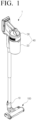
- FIG. 1 is a perspective view of a vacuum cleaner 1 according to an embodiment of the disclosure.
- the vacuum cleaner 1 may include a cleaner body 40 including a driver 30 configured to generate a suction force for sucking dust and a dust container 20 configured to collect sucked dust, a cleaner head 100 provided to suck foreign material from a surface to-be-cleaned S (see FIG. 8 ) by the suction force, and a nozzle 10 connecting the cleaner head 100 with the cleaner body 40.
- the cleaner body 40 may be a wired type or a wireless type depending on a way how the driver 30 is operated.
- the vacuum cleaner 1 may be a wired vacuum cleaner.
- the vacuum cleaner 1 may be a wireless vacuum cleaner.
- the cleaner body 40 may include a handle portion for user convenience, and the handle portion may have various shapes.
- the dust container 20 may store dust sucked from the cleaner head 100.
- the dust container 20 may be detachably connected to the cleaner body 40 and may be separated therefrom for the user convenience.
- the driver 30 is a device that generates suction power of the vacuum cleaner 1, and may include a motor (not shown) and a blade rotated by the motor.
- the nozzle 10 may connect the cleaner head 100 with the cleaner body 40 to move the dust sucked from the cleaner head 100 to the cleaner body 40.
- the nozzle 10 may have various shapes as needed.
- the cleaner head 100 may be provided to suck the foreign material such as dust on the surface to-be-cleaned while being moved in contact with the surface to-be-cleaned. A detailed structure of the cleaner head 100 is described below.
- FIG. 2 is a top perspective view of a cleaner head 100 according to an embodiment of the disclosure
- FIG. 3 is a bottom perspective view of the cleaner head 100 according to an embodiment of the disclosure
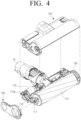
- FIG. 4 is an exploded perspective view of the cleaner head 100 according to an embodiment of the disclosure.
- the cleaner head 100 may include: a case 140 disposed close to an inlet 11 of the nozzle 10; and a brush 110 rotatably disposed in the case 140.
- the brush 110 may be rotatably disposed in the case 140, and thus be rotated in a predetermined direction.
- the brush 110 may have a cylindrical shape, and a material having high adhesion to the dust on the surface to-be-cleaned S may be disposed on an outer circumferential surface of the brush 110.
- the suction force generated by the driver 30 acts and the brush 110 rotates simultaneously, so that the dust accumulated on the surface to-be-cleaned S may be moved toward the inlet 11 of the nozzle 10. That is, the brush 110 may sweep the dust accumulated on the surface to-be-cleaned S.
- the brush 110 may have various shapes, and may be referred to as a brush drum or the like as needed.
- a rotating shaft 111 of the brush 110 may be connected to a motor shaft 113a of a brush motor 113 embedded in the cleaner head 100 through a drive belt 112. Accordingly, a driving force of the motor shaft 113a rotated by an operation of the brush motor 113 may be transmitted to the brush 110 through the drive belt 112, and the brush 110 may be rotated in the predetermined direction.
- the predetermined direction may refer to a direction in which a bottom surface of the brush 110 is moved in a direction in which the inlet 11 of the nozzle 10 is disposed. Accordingly, as the brush 110 is rotated, the dust on the surface to-be-cleaned S may be guided to the inlet 11 by the rotation of the brush 110.
- the case 140 may form an outer shape of the cleaner head 100, and may have a shape in which the case 140 is communicated with the outside only in a region adjacent to the brush 110. Accordingly, the case 140 may be communicated with the outside only in the predetermined region, thereby improving suction efficiency of the vacuum cleaner 1.
- the case 140 may be provided to partially expose an outer circumferential surface of the brush 110. That is, the case 140 may be formed to expose a lower region of the brush 110 and a region adjacent to the inlet 11.
- the dust on the surface to-be-cleaned S in contact with the exposed lower region of the brush 110 and the region adjacent to the inlet 11 may be sucked into the inlet 11.
- the case 140 may include a main case 120 connected to the brush 110 and including a shielding surface 121 formed to extend forward than an outer region of the brush 110, and a side case 130 connected to the main case 120 and having an air passage groove 131 formed in its outer side surface.
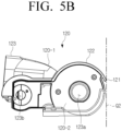
- FIG. 5A is a perspective view of a main case 120 according to an embodiment of the disclosure
- FIG. 5B is a side view of the main case 120 according to an embodiment of the disclosure.
- the main case 120 may include a first main case 120-1 disposed to expose a portion of the brush 110, and a second main case 120-2 connected to the first main case 120-1 and having a fixing hole 123a in which the rotating shaft 111 of the brush 110 is disposed.
- the first main case 120-1 may cover a top side of the cleaner head 100, and may include a bent portion 122 having a shape corresponding to that of the brush 110, a nozzle connection portion 123 connected to the nozzle 10, and the shielding surface 121 formed to extend from the bent portion 122.
- the bent portion 122 may be spaced apart from the outer circumferential surface of the brush 110 and may cover a top region of the brush 110. Accordingly, the bent portion 122 may protect the rotated brush 110 from external impact. In addition, the bent portion 122 may be formed not to extend to the lower region of the brush 110 and thus expose the lower region of the brush 110. Therefore, the lower region of the brush 110 may be exposed through a front surface of the main case 120.
- the nozzle connection portion 123 may have various shapes as long as the nozzle connection portion 123 connects the case 140 with the nozzle 10.
- the shielding surface 121 may be formed to extend further forward than the brush 110 from the bent portion 122.
- the shielding surface 121 may be disposed in a direction parallel to the rotating shaft 111 of the brush 110 and disposed to protrude most from the case 140 toward a front of the cleaner head 100.
- the shielding surface 121 of the cleaner head 100 may be brought into contact with the front wall surface Q2.
- the shielding surface 121 may first make contact with the front wall surface Q2.
- the shielding surface 121 may have a predetermined area or more to make surface contact with the front wall surface Q2 of the surface to-be-cleaned S.
- a contact surface in which the shielding surface 121 is in contact with the front wall surface Q2 may have the predetermined area or more.
- the shielding surface 121 makes contact with the front wall surface Q2, it is possible to reduce or prevent the air above the case 140 from being moved to a to-be-cleaned region C (see FIG. 8 ) under the shielding surface 121 through the shielding surface 121.
- the vacuum cleaner 1 may have improved suction efficiency with the same suction power due to sucking dust only in the to-be-cleaned region C substantially sealed from the outside. That is, the vacuum cleaner 1 may have the improved suction efficiency by reducing suction of outside air other than the air in the to-be-cleaned region C.
- the shielding surface 121 may be made of an elastic material. Accordingly, in case that the shielding surface 121 makes contact with the front wall surface Q2, actual shielding efficiency of the to-be-cleaned region C may be improved.
- the shielding surface 121 itself may not be limited to being made of the elastic material, and a separate elastic member may be coupled to the shielding surface 121.
- the second main case 120-2 may cover a side surface of the cleaner head 100. That is, the first main case 120-1 may cover the top surface of the cleaner head 100, and the second main case 120-2 may cover the side surface of the cleaner head 100.
- the second main case 120-2 may include: the fixing hole 123a into which the rotating shaft 111 of the brush 110 is inserted; and a motor shaft hole 123b into which the brush motor shaft 113a of the brush motor 113 is inserted.
- the second main case 120-2 may support the rotating shaft 111 of the brush 110 and the brush motor shaft 113a of the brush motor 113 to allow the rotating shaft 111 of the rotated brush 110 and the brush motor shaft 113a of the brush motor 113 to be stably rotated.
- the second main case 120-2 may form an inner space in which the drive belt 112 is disposed together with the side case 130 coupled to the second main case 120-2, thereby protecting the drive belt 112 from the external impact and preventing the foreign material from being introduced into the drive belt 112.
- the second main case 120-2 may be integrally formed with the first main case 120-1.
- the first main case 120-1 and the second main case 120-2 may be injection molded together.
- FIG. 6 is a perspective view of the side case 130 according to an embodiment of the disclosure.
- the side case 130 may be connected to the second main case 120-2 to cover the fixing hole 123a.
- the side case 130 may have a shape corresponding to that of the second main case 120-2, and may cover the fixing hole 123a and the motor shaft hole 123b.
- the side case 130 may be disposed on each of both sides of the cleaner head 100.
- the side case 130 may be connected to the second main case 120-2 through a connection portion 133 of the side case 130.
- the side case 130 may include a side surface 132 perpendicular to the surface to-be-cleaned S and the air passage groove 131 disposed in the outer side surface 132 of the side case 130 and having a passage formed to be narrowed from an edge region 131b of the case 140 toward the surface to-be-cleaned S.
- the edge region 131b of the case 140 may refer to an edge region in which the side surface and a top surface of the case 140 are in contact with each other.
- the side surface 132 may be a surface making contact with a side wall surface Q1, and may be formed to be flat.
- the air passage groove 131 may be formed in the side surface 132.
- the air outside the case 140 may be prevented from being moved on the side surface 132 and may be moved only through the air passage groove 131.
- a passage enclosed by the air passage groove 131 and the side wall surface Q1 may be formed.
- the side surface 132 may improve flow efficiency of the air moved to the air passage groove 131 through surface contact of the cleaner head 100 with the side wall surface Q1.
- the air passage groove 131 may be formed in the outer side surface 132 of the side case 130, and include one end 131a disposed toward the surface to-be-cleaned S and the other end 131b disposed toward the edge region of the case 140. That is, the air passage groove 131 may refer to one passage formed in the outer side surface 132 of the side case 130.
- the other end 131b may be referred to the same as the edge region of the case 140.
- the other end 131b may be various positions of the edge of the case 140.
- the air passage groove 131 may introduce the air outside the case 140 and blow the introduced air to the to-be-cleaned region C by the suction force of the nozzle 10.
- the air passage groove 131 may include a first air passage groove 131-1 having a first cross-sectional area and the one end 131a disposed toward the surface to-be-cleaned S and a second air passage groove 131-2 connected to the first air passage groove 131-1 and having a second cross-sectional area greater than the first cross-sectional area toward the edge region 131b of the case. That is, the first air passage groove 131-1 and the second air passage groove 131-2 may form one passage together.
- the first cross-sectional area may refer to a cross-sectional area of the groove of the first air passage groove 131-1, and may refer to an area having a first width w1 and a first depth t1.
- the second cross-sectional area may refer to a cross-sectional area of the groove of the second air passage groove 131-2, and may refer to an area having a second width w2 and a second depth t2.
- the second width w2 of the second air passage groove 131-2 may be greater than the first width w1 of the first air passage groove 131-1.
- the second air passage groove 131-2 may have a smaller width as it is closer to the first air passage groove 131-1 from the edge region 131b of the case 140.
- the air moved from the second air passage groove 131-2 having the second cross-sectional area may pass through the first air passage groove 131-1 having the first cross-sectional area smaller than the second cross-sectional area, and may thus have an increased flow velocity.
- the air passed through the one end 131a of the first air passage groove 131-1 may flow rapidly into the to-be-cleaned region C, thereby improving the effect of blowing the air into the to-be-cleaned region C.
- the flow velocity of the air introduced from the outside of the case 140 may be increased even with the same suction force of the vacuum cleaner 1 through a structural shape in which the second air passage groove 131-2 has a smaller width as it is closer to the first air passage groove 131-1 from the edge region 131b of the case 140.
- a cross section of the air passage groove 131 may have various shapes as needed.
- first air passage groove 131-1 and the second air passage groove 131-2 may have the same depth.
- first depth t1 and the second depth t2 may be the same.
- first depth t1 and the second depth t2 may be formed differently from each other.
- the air passage groove 131 may be disposed at a position corresponding to a position at which the rotating shaft 111 of the brush 110 is disposed. In addition, the air passage groove 131 may be formed toward an exposed region of the brush 110.
- the exposed region of the brush 110 may refer to a portion of the brush 110 that is not covered by the case 140.
- the one end 131a of the air passage groove 131 may be disposed adjacent to a front bottom portion of the brush 110, and simultaneously, the air passage groove 131 may be formed in the shortest length, thereby preventing the flow velocity of the air introduced from the outside of the case 140 from being reduced due to friction and the like.
- the air passage groove 131 may be operated only in case that the side surface 132 makes contact with the side wall surface Q1.
- the air passage groove 131 may be operated in case that the cleaner head 100 is disposed at the corner region between the wall surfaces, thereby improving the suction efficiency of the vacuum cleaner 1 when cleaning a normal flat surface.
- the side case 130 may include bristles 150 adjacent to the brush 110 and arranged along a bottom edge of the side case 130.
- the bristles 150 may improve cleaning efficiency of the vacuum cleaner 1 by making contact with the surface to-be-cleaned S to sweep the dust accumulated on the surface to-be-cleaned S or allow the dust to be first attached thereto and then the attached dust to be sequentially sucked into the vacuum cleaner 1.
- the bristles 150 may improve shielding effect of the to-be-cleaned region C by making contact with the surface to-be-cleaned S and with the front wall surface Q2.
- the one end 131a of the air passage groove 131 may be formed toward the bristles 150. Accordingly, in case that the dust is attached to and accumulated on the bristles 150, the air introduced through the air passage groove 131 may shake the dust from the bristles 150 and scatter the dust within the to-be-cleaned region C, thereby improving the cleaning efficiency of the vacuum cleaner 1.
- the bristles 150 may be arranged along a bottom edge of the case 140, adjacent to the surface to-be-cleaned S.
- the bristles 150 is not limited to improving the cleaning efficiency of the vacuum cleaner 1, and may be made of various materials such as the elastic material, a plastic injection material, and a sealing member to implement the shielding effect of the to-be-cleaned region C.
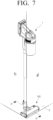
- FIG. 7 is a schematic view showing a state in which the vacuum cleaner 1 according to an embodiment of the disclosure is disposed at a corner between wall surfaces;
- FIG. 8A is a side view of a portion of FIG. 7 ;
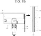
- FIG. 8B is a top view of the portion of FIG. 7 ;
- FIG. 9 is a cross-sectional view taken along line A-A of FIG. 7 .
- the cleaner head 100 of the vacuum cleaner 1 may be disposed at a corner region between the wall surfaces to clean a corner portion between the wall surfaces.
- the corner region between the wall surfaces may be formed of the surface to-be-cleaned S which is a floor, the side wall surface Q1 and the front wall surface Q2.
- the side wall surface Q1 may refer to a wall surface facing the side case 130 of the cleaner head 100
- the front wall surface Q2 may refer to a wall surface facing the shielding surface 121.
- the case 140 may make contact with the front wall surface Q2, and thereby the cleaner head 100 may form the to-be-cleaned region C which is a space between the surface to-be-cleaned S and the front wall surface Q2.
- the shielding surface 121 of the cleaner head 100 may make contact with the front wall surface Q2, and then the shielding surface 121 may prevent the air outside the case 140 from being introduced into the to-be-cleaned region C.
- the suction force of the vacuum cleaner 1 may not be used to introduce the air outside the case 140 and may be used to suck the dust in the to-be-cleaned region C. Therefore, the suction force may not be wasted, thereby improving the suction efficiency of the vacuum cleaner 1.
- the side case 130 may make contact with the side wall surface Q1.
- the side surface 132 of the side case 130 may make contact with the side wall surface Q1.
- the air outside the case 140 may be prevented from being introduced through the side surface 132 of the side case 130, and may be introduced into the to-be-cleaned region C only through the air passage groove 131 formed in the side case 130.
- the air outside the case 140 may be introduced into the air passage groove 131 by the suction force of the vacuum cleaner 1.
- the air outside the case 140 may form a second air flow P2 through the second air passage groove 131-2, and may form a first air flow P1 through the first air passage groove 131-1 connected to the second air passage groove 131-2.
- the first cross-sectional area of the first air passage groove 131-1 may be smaller than the second cross-sectional area of the second air passage groove 131-2, and a flow velocity of the first air flow P1 may be faster than a flow velocity of the second air flow P2.
- the first air flow P1 may form a third air flow P3 that is rapidly moved through the one end 131a adjacent to the to-be-cleaned region C, and the air in the third air flow P3 may scatter the dust accumulated in the corner region between the wall surfaces.
- the scattered dust may be moved together with a fourth air flow P4 introduced into the nozzle 10, so that efficiency of removing the dust from the corner region between the wall surfaces may be significantly improved. That is, the air moved through the air passage groove 131 may remove the dust from the region where the brush 110 and the bristles 150 fail to sweep.
- the air passage groove 131 formed in the one side surface of the case 140 of the cleaner head 100 has a narrower width toward the surface to-be-cleaned S.
- the air passage groove 131 may not be limited to this shape.
- the air passage groove may be formed to have a constant width.
- FIG. 10 is a view showing another example of the air passage groove of the side case 130 according to an embodiment of the disclosure.
- an air passage groove 131' may be formed to have a constant width in the one side surface of the case 140 (see FIG. 2 ).
- the air passage groove 131' may be formed in the one side surface of the side case 130 to have the constant width from the edge region of the case 140 toward the surface to-be-cleaned S.
- the air passage groove 131' may form an air passage through which the air passes, together with the side wall surface Q1, and the air above the case 140 may flow into the corner region between the wall surfaces through the air passage groove 131' formed in the side case 130. Then, the dust in the corner region between the wall surfaces may be scattered and removed.
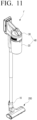
- FIG. 11 is a perspective view of the vacuum cleaner 1' according to another embodiment of the disclosure.
- the vacuum cleaner 1' may include a cleaner body 40 including a driver 30 generating a suction force for sucking dust and a dust container 20 collecting sucked dust, a cleaner head 200 provided to suck foreign material from a surface to-be-cleaned S (see FIG. 17 ) by suction force of the driver 30, and a nozzle 10 connecting the cleaner head 200 with the cleaner body 40.
- the cleaner body 40 may be a wired type or a wireless type depending on a way how the driver 30 is operated.
- the vacuum cleaner 1' may be a wired vacuum cleaner.
- the vacuum cleaner 1' may be a wireless vacuum cleaner.
- the cleaner body 40 may include a handle portion for user convenience, and the handle portion may have various shapes.
- the dust container 20 may store dust sucked from the cleaner head 200.
- the dust container 20 may be detachably disposed to the cleaner body 40, and may be separated from the cleaner body 40 to empty the dust collected therein.
- the driver 30 is a device that generates suction force of the vacuum cleaner 1', and may include a motor (not shown) and a blade (not shown) rotated by the motor.
- the nozzle 10 may connect the cleaner head 200 with the cleaner body 40 to move the dust sucked from the cleaner head 200 to the cleaner body 40.
- the nozzle 10 may have various shapes as needed.
- the cleaner head 200 may be provided to suck the foreign material such as dust on the surface to-be-cleaned S while being moved in contact with the surface to-be-cleaned S. A detailed structure of the cleaner head 200 is described below.
- the cleaner head 200 according to another embodiment of the disclosure is described with reference to FIGS. 12 to 14 .
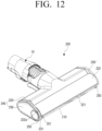
- FIG. 12 is a perspective view of the cleaner head 200 according to another embodiment of the disclosure
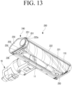
- FIG. 13 is a bottom perspective view of the cleaner head 200 according to another embodiment of the disclosure
- FIG. 14 is an exploded perspective view of the cleaner head 200 according to another embodiment of the disclosure.
- the cleaner head 200 may include a case 240 disposed close to an inlet 11 of the nozzle 10 and a brush 210 rotatably disposed in the case 240.
- the brush 210 may be rotatably disposed inside the case 240, and thus be rotated in a predetermined direction.
- the brush 210 may have a cylindrical shape and a material having high adhesion to the dust on the surface to-be-cleaned S may be disposed on its outer circumferential surface.
- the brush 210 may be rotated at the same time as the dust is sucked by the suction force generated by the driver 300, so that the dust on the surface to-be-cleaned S may be moved toward the inlet 11 of the nozzle 10. That is, the brush 210 may sweep the dust on the surface to-be-cleaned S.
- the brush 210 may have various shapes, and may be referred to as a brush drum or the like as needed.
- a rotating shaft 211 of the brush 210 may be connected to a motor shaft 213a of a brush motor 213 embedded in the cleaner head 200 through a drive belt 212 and pulleys 214 and 215. Accordingly, a driving force of the motor shaft 213a rotated by an operation of the brush motor 213 may be transmitted to the brush 210 through the drive belt 212 and the pulleys 214 and 215, and the brush 210 may be rotated in the predetermined direction.
- the predetermined direction may refer to a direction in which a bottom surface of the brush 210, which is in contact with the surface to-be-cleaned S, is moved in a direction in which the inlet 11 of the nozzle 10 is disposed. Accordingly, as the brush 210 is rotated, the dust on the surface to-be-cleaned S may be moved toward the inlet 11 by the rotation of the brush 210.
- the case 240 may form an outer shape of the cleaner head 200, and have an open bottom for the brush 210 to be disposed therein.
- the case 240 may be formed to expose a portion of an outer circumferential surface of the brush 210.
- the case 240 may have the open bottom to expose a lower region of the brush 210 and a region adjacent to the inlet 11.
- the dust on the surface to-be-cleaned S in contact with the exposed lower region of the brush 210 and the region adjacent to the inlet 11 may be sucked into the inlet 11.
- a front surface of the case 240 may be partially open. That is, a lower end of the front surface of the case 240 may be formed to be spaced apart by a predetermined distance from the surface to-be-cleaned S. Therefore, a lower front portion of the brush 210 may be exposed through the front surface of the case 240.
- the case 240 may include an air passage 201 formed at each of opposite side ends of the front surface of the case 240 and allowing air to flow from above the case 240 to below the case 240, that is, toward the surface to-be-cleaned S. Therefore, in case that the front surface of the case 240 makes contact with the wall surface, the outside air may flow to the surface to-be-cleaned S along the air passage 201 of the case 240.
- the case 240 may include a main case 220 connected to the brush 210 and including a shielding surface 221 formed to extend forward than the brush 210, and a side case 230 installed at the main case 220 and forming the air passage 201.
- FIG. 15 is a perspective view of a main case 220 according to an embodiment of the disclosure.
- the main case 220 may include a first main case 220-1 disposed to expose a portion of the brush 210 and a second main case 220-2 connected to the first main case 220-1 and having a fixing hole 223a into which the rotating shaft 211 of the brush 210 is inserted.
- the first main case 220-1 may form a top surface of the cleaner head 200, and may include a bent portion 222 having a shape corresponding to that of the brush 210, a nozzle connection portion 223 connected to the nozzle 10, and the shielding surface 221 formed to extend from the bent portion 222.
- the bent portion 222 may be spaced apart from the outer circumferential surface of the brush 210 and may cover a top region of the brush 210. Accordingly, the bent portion 222 may protect the rotated brush 210 from external impact. In addition, the bent portion 222 may be formed not to extend to the lower region of the brush 210 for the lower region of the brush 210 to be exposed.
- the nozzle connection portion 223 may be formed to connect the case 240 with the nozzle 10, and have various shapes as long as the nozzle connection portion 223 can connect the case 240 with the nozzle 10.
- the shielding surface 221 may be formed to extend forward than the brush 210 from the bent portion 222.
- the shielding surface 221 may have the same length as the bent portion 222, be disposed in a direction parallel to the rotating shaft 211 of the brush 210 and protrude most from the case 240 toward a front of the cleaner head 200.
- a lower end of the shielding surface 221 may be disposed at approximately the same level as the rotating shaft 211 of the brush 210.
- the case 240 is opened under shielding surface 221, so that the lower region of the brush 210 may be exposed. That is, when viewed from the front of the cleaner head 200, the lower region of a front surface of the brush 210 may be seen under the shielding surface 221. Therefore, the suction force of the vacuum cleaner 1' may not be applied in front of the brush 210.
- the shielding surface 221 of the cleaner head 200 may be brought into contact with the front wall surface Q2.
- the shielding surface 221 may be first brought into contact with the front wall surface Q2.
- the shielding surface 221 may have a predetermined area or more to make surface contact with the front wall surface Q2.
- the shielding surface 221 may be formed to have a length corresponding to that of the bent portion 222 and a predetermined width.
- the shielding surface 221 makes contact with the front wall surface Q2, it is possible to reduce or prevent the air above the case 240 from being moved to a to-be-cleaned region C (see FIG. 18A ) under the shielding surface 221 through the shielding surface 221.
- the vacuum cleaner 1' may have improved suction efficiency with the same suction force by sucking dust only in the to-be-cleaned region C substantially sealed from the outside. That is, the cleaner head 200 may improve the suction efficiency of the vacuum cleaner 1' by reducing suction of the outside air other than the air in the to-be-cleaned region C.
- the shielding surface 221 may be made of an elastic material. Accordingly, in case that the shielding surface 221 makes contact with the front wall surface Q2, actual shielding efficiency of the to-be-cleaned region C may be improved.
- the shielding surface 221 itself may not be limited to being made of the elastic material, and a separate elastic member may be coupled to the shielding surface 221.
- the separate shielding surface 221 is formed on a front end of the bent portion 222.
- the front end of the bent portion 222 adjacent to the brush 210 may be formed to directly make contact with the front wall surface Q2.
- the front end of the bent portion 222 may function to shield the outside air.
- the second main case 220-2 may be formed to be perpendicular to a lower surface of the first main case 220-1 to support and fix the side case 230. Accordingly, the first main case 220-1 may form the top surface of the cleaner head 200, and the second main case 220-2 may support the side case 230.
- the second main case 220-2 may include a through hole 223a through which the rotating shaft 211 of the brush 210 penetrates and a plurality of fixing portions 225 capable of fixing the side case 230.
- Each of the plurality of fixing portions 225 may have a female screw.
- the side case 230 may be fixed to the second main case 220-2.
- the second main case 220-2 may be integrally formed with the first main case 220-1.
- the first main case 220-1 and the second main case 220-2 may be injection molded together.
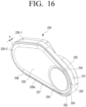
- FIG. 16 is a perspective view of the side case 230 according to an embodiment of the disclosure.
- the side case 230 may be installed at the second main case 220-2.
- the side case 230 may have a shape corresponding to that of the second main case 220-2.
- the side case 230 may include a side case body 230-1 fixed to the second main case 220-2 and a side case cover 230-2 covering an opening of the side case body 230-1.
- the side case body 230-1 may have a shape corresponding to that of the second main case 220-2, and may be formed in a shape of a container having a bottom surface. A top surface of the side case body 230-1 may be opposite to the bottom surface and open.
- the pulleys 214 and 215 and the drive belt 212 may be accommodated in an inner space of the side case body 230-1.
- the bottom surface 230c of the side case body 230-1 may have thereon, a fixing hole 230a to which the through hole 223a of the second main case 220-2 corresponds and into which the rotating shaft 211 of the brush 210 is inserted, and a motor shaft hole 230b into which the brush motor shaft 213a of the brush motor 213 is inserted.
- the side case 230 may support the rotating shaft 211 of the brush 210 and the brush motor shaft 213a of the brush motor 213 to stably rotate the rotating shaft 211 of the rotated brush 210 and the brush motor shaft 213a of the brush motor 213.
- the side case body 230-1 may form a space in which the pulleys 214 and 215 and the drive belt 212 are disposed, together with the side case cover 230-2 coupled to the side case body 230-1, thereby protecting the pulleys 214 and 215 and the drive belt 212 from the external impact and preventing the foreign material from being attached to the drive belt 212.
- a coupling portion 233 coupled to the bent portion 222 of the main case 220 may be disposed on one side of the top surface of the side case body 230-1.
- the side case cover 230-2 may be coupled to the opening of the side case body 230-1 to form the side case 230, and protect the inner space of the side case body 230-1.
- a side case 230' may be installed on the opposite side surface of the cleaner head 200.
- the side case 230' installed on the opposite side surface of the cleaner head 200 may be formed symmetrically with the side case 230 shown in FIG. 16 , and any pulley or drive belt is not installed therein.
- the side case 230 may form a step with a front surface of the main case 220.
- the bent portion 222 and the shielding surface 221 of the main case 220 may further protrude than an outer circumferential surface of the side case 230. Therefore, the side case 230 may form the step with the front surface of the main case 220, that is, the bent portion 222 and the shielding surface 221.
- the air passage 201 through which the air above the main case 220 flows downward may be formed by the step between the side case 230 and the front surface of the main case 220.
- the side case 230 may be spaced apart from the front wall surface Q2
- one side end 222a of the front surface of the main case 220 may be spaced apart from the side wall surface Q1 to form the air passage 201.
- the side case 230 may include an air guide surface 231 forming a front surface of the side case 230 and spaced from the front surface of the main case 220 to form the step, and a side surface 232 perpendicular to the surface to-be-cleaned S.
- the side surface 232 may be a surface making contact with a side wall surface Q1, and may be formed to be flat. Accordingly, in case that the side surface 132 makes contact with the side wall surface Q1, the air outside the case 240 may be prevented from being moved between the side surface 232 and the side wall surface Q1, and may be moved only through the air guide surface 231 of the side case 230.
- the air guide surface 231 may be formed on the front surface of the side case 230, and may form the step with the front surface of the main case 220. That is, the air guide surface 231 may form the air passage 201 through which the air flows, together with the front surface of the main case 220, that is, the one side end 222a of the bent portion 222.
- the step between the front surface 231 of the side case 230 and the front surface of the main case 220 may introduce the air outside the case 240 by the suction force of the vacuum cleaner 1' and blow the introduced air into the to-be-cleaned region C.
- the dust in the to-be-cleaned region C may be scattered within the to-be-cleaned region C by the air passed through the air passage 201, and the scattered dust may be sucked into the nozzle 10 through the suction force of the vacuum cleaner 1' and the brush 210.
- the side case 230 may further include a sub air passage 202 formed on one side of the air passage 201.
- the sub air passage 202 may be formed as a side step portion 234 formed along a circumference of the side surface 232. That is, in case that the side step portion 234 is formed between the air guide surface 231 and the side surface 232 of the side case 230, the side step portion 234 may form the sub air passage 202 guiding the air above the case 240 toward the bottom of the cleaner head 200.
- the side step portion 234 may form the sub air passage 202 through which the air passes, together with the side wall surface Q1 (see FIG. 18B ).
- the air passage 201 may be operated only in case that the shielding surface 221 of the main case 220 makes contact with the front wall surface Q2 and the side surface 232 of the side case 230 makes contact with the side wall surface Q1.
- the shielding surface 221 of the main case 220 and the side surface 232 of the side case 230 are not brought into contact with the front wall surface Q2 and the side wall surface Q1, respectively, there may not be formed the air passage 201 through which the air flows by the air guide surface 231 of the side case 230 and the one side end 222a of the front surface of the main case 220.
- the air passage 201 may be operated in case that the cleaner head 200 is disposed at the corner region between the wall surfaces, thereby improving the suction efficiency of the vacuum cleaner 1' when generally cleaning the surface to-be-cleaned.
- the suction efficiency of the vacuum cleaner 1' may not be reduced by the air passage 201 disposed at each of the opposite ends of the front surface of the case 240.
- the side case 230 may include bristles 250 adjacent to the brush 210 and arranged along a bottom surface 236 of the side case 230.
- the bristles 250 may improve cleaning efficiency of the vacuum cleaner 1' by making contact with the surface to-be-cleaned S to sweep the dust accumulated on the surface to-be-cleaned S or allow the dust to be first attached thereto and then the attached dust to be sequentially sucked into the vacuum cleaner 1'.
- the bristles 250 may be arranged along a bottom edge of the case 240, adjacent to the surface to-be-cleaned S.
- the bristles 250 may be arranged in such a manner that a front end portion of the bristles 250 does not interfere with the air flow moved to the to-be-cleaned region C along the air passage 201 on the front surface of the side case 230. Dust attached to the front end portion of the bristles 250 may be removed by the air flow moved through the air passage 201.
- the bristles 250 may be arranged to be spaced apart by a predetermined distance from an edge of the bottom surface 236 of the side case 230. Then, a lower step formed by a portion of the bottom surface 236 of the side case 230 and the bristles 250 may form a lower air passage 203. That is, the lower air passage 203 may be formed on the bottom surface 236 of the side case 230 by the bristles 250 arranged along the edge of the bottom surface of the side case 230.
- the lower step between the bristles 250 and the bottom surface 236 of the side case 230 may form the air passage through which the outside air flows, i.e. lower air passage 203, together with the side wall surface Q 1 and the surface to-be-cleaned S (see FIG. 18C ).
- the outside air may flow to the corner between the wall surfaces through the lower air passage 203.
- the lower air passage 203 has a small cross-sectional area, a flow velocity of the air passing through the lower air passage 203 may be increased, such that dust in the corner region between the wall surfaces may be blown away.
- the air passing through the lower air passage 203 may remove the dust attached to the bristles 250.
- the side case 230 may further include a sub lower air passage 204 formed on one side of the lower air passage 203.
- the sub lower air passage 204 may be formed as a lower side step portion 237 formed along a lower end 232b of the side surface 232. That is, in case that the lower side step portion 237 is formed between the bottom surface 236 of the side case 230 and the lower end 232b of the side surface 232, the lower side step portion 237 may form the sub lower air passage 204 guiding the air behind the cleaner head 200 toward the front of the cleaner head 200.
- the lower side step portion 237 when the cleaner head 200 is disposed at the corner region between the wall surfaces, the lower side step portion 237 may form the sub lower air passage 204 through which the air passes, together with the side wall surface Q 1 and the surface to-be-cleaned S.
- the vacuum cleaner 1' may improve cleaning efficiency of removing the dust from the to-be-cleaned region C of the corner between the wall surfaces.
- the above-described sub air passage 202 and sub lower air passage 204 may be formed by forming the step portion along the circumference of the side surface 232 of the side case 230.
- the lower side step portion 237 formed on the lower end 232b of the side surface 232 and the side step portion 234 formed on the front surface of the side surface 232 may be connected to each other. Accordingly, the side surface 232 may further protrude to a predetermined height (h) than the one side end of the outer circumferential surface of the side case 230.
- the embodiment shown in FIG. 13 describes the case where the bristles 250 are arranged to be spaced apart by the predetermined distance from the edge of the bottom surface 236 of the side case 230.
- the portion of the bottom surface 236 of the side case 230 and the bristles 250 may form the lower air passage 203, and the sub lower air passage 204 may be formed by forming the lower side step portion 237 between the lower end 232b of the side surface 232 and the bottom surface 236 of the side case 230.
- the bristles 250 may be arranged to coincide with the edge of the bottom surface 236 of the side case 230.
- no step portion may be formed between the bottom surface 236 of the side case 230 and the bristles 250, and only the lower side step portion 237 may be formed between the bottom surface 236 of the side case 230 and the lower end 232b of the side surface 232.
- the lower side step portion 237 may function as the lower air passage 203 guiding the air behind the cleaner head 200 to the front of the cleaner head 200.
- the bristles 250 may be made of a material capable of improving the cleaning efficiency of the vacuum cleaner 1'.
- the bristles 250 may be made of various materials such as the elastic material, a plastic injection material, and a sealing member to implement shielding effect of the cleaner head 200.
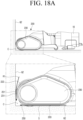
- FIG. 17 is a perspective view showing a state in which the vacuum cleaner 1' according to another embodiment of the disclosure is disposed at the corner between wall surfaces;
- FIG. 18A is a side view of the cleaner head of the vacuum cleaner of FIG. 17 ; and
- FIG. 18B is a plan view of the cleaner head of the vacuum cleaner of FIG. 17 .
- FIG. 18C is a rear view of the cleaner head of the vacuum cleaner of FIG. 17 ; and
- FIG. 18D is a bottom view of the cleaner head of the vacuum cleaner of FIG. 17 .
- FIG. 19 is a cross-sectional view taken along line B-B of FIG. 17 .
- the cleaner head 200 of the vacuum cleaner 1' may be disposed at the corner region between the wall surfaces to clean the corner portion between the wall surfaces.
- the corner region between the wall surfaces may be formed of the surface to-be-cleaned S which is a floor, the side wall surface Q 1 and the front wall surface Q 2 .
- the side wall surface Q 1 may refer to a wall surface facing the side case 230 of the cleaner head 200
- the front wall surface Q 2 may refer to a wall surface facing the shielding surface 221.
- the case 240 may contact the front wall surface Q 2 , and thereby the cleaner head 200 may form the to-be-cleaned region C which is a space between the surface to-be-cleaned S and the front wall surface Q 2 .
- the shielding surface 221 of the cleaner head 200 may make contact with the front wall surface Q 2 , and therefore the air outside the case 240 may not be introduced into the to-be-cleaned region C by the shielding surface 221.
- the suction force of the vacuum cleaner 1' may not be used to introduce the air outside the case 240 and may be used to suck the dust in the to-be-cleaned region C. Therefore, the suction force may not be wasted, thereby improving the suction efficiency of the vacuum cleaner 1'.
- the side case 230 may make contact with the side wall surface Q 1 .
- the side surface 232 of the side case 230 may make contact with the side wall surface Q 1 .
- the air outside the case 240 may be prevented from being introduced through the side surface 232 of the side case 230, and may be introduced into the to-be-cleaned region C only through the air passage 201 formed on the side case 230.
- the air above the case 240 may be introduced into the air passage 231 by the suction force of the vacuum cleaner 1', which is generated in case that the vacuum cleaner 1' disposed in the corner region between the wall surfaces is operated as shown in FIG. 17 .
- the air above the case 240 may form a first air flow R1 moved from above the case 240 toward the surface to-be-cleaned S through the air passage 201 formed by the air guide surface 231 of the side case 230, the one side end 222a of the front surface of the main case 220, the front wall surface Q2 and the side wall surface Q1.
- the air above the case 240 may be moved toward the surface to-be-cleaned S also through the sub air passage 202.
- the air passage 201 has a very small cross-sectional area and the air flow passing through the air passage 201 may thus have a fast flow velocity.
- the air flow R1 passed through the air passage 201 may scatter the dust in the corner region between the wall surfaces.
- the air behind the cleaner head 200 may be introduced into the lower air passage 203 by the suction force of the vacuum cleaner 1'.
- the air behind the cleaner head 200 may form a second air flow R2 moved from behind the cleaner head 200 toward the front wall surface Q2 through the lower air passage 203 formed by the bottom surface 236 of the side case 230, the side surface of the bristles 250, the side wall surface Q1 and the surface to-be-cleaned S.
- the air behind the cleaner head 200 may be moved toward the front wall surface Q2 also through the sub lower air passage 204.
- the lower air passage 203 has a small cross-sectional area and the air flow passing through the lower air passage 203 may thus have a fast flow velocity.
- the dust in the corner region between the wall surfaces may be scattered also by the air flow R2 passed through the lower air passage 203.
- the air flow R2 passing through the lower air passage 203 may remove the dust attached to the bristles 250 and scatter the dust within the to-be-cleaned region C.
- the dust scattered by the air flows R1 and R2 passed through the air passage 201 and the lower air passage 203, respectively, may be moved along the air flow R3 sucked into the nozzle 10. Therefore, the air passage 201 and the lower air passage 203 of the cleaner head 200 may efficiently remove the dust from the corner region between the wall surfaces. That is, the air moved through the air passage 201 and the lower air passage 203 may remove the dust from the region where the brush 210 and the bristles 250 fail to sweep.
- the cleaner head 200 may improve dust removal efficiency of removing the dust from the corner region between the wall surfaces.
Description
- Apparatuses and methods consistent with the disclosure relate to a cleaner head having improved suction efficiency and a vacuum cleaner having the same.
- A vacuum cleaner is a device that performs cleaning by sucking a foreign material including dust together with the air by generating suction power, and then removing the foreign material using a dust collector or the like.
- The vacuum cleaner may suck the foreign material including the dust through a cleaner head making contact with a dusted and surface to-be-cleaned. However, suction on a corner between wall surfaces is not smooth due to shape and volume of the cleaner head itself.
-
US6058561 relates to a vacuum cleaner suction apparatus having a certain shape of air inlet formed between a lower cover and a first diaphragm to suck outside air when suction force is generated by a motor. - Embodiments of the disclosure overcome the above disadvantages and other disadvantages not described above. In addition, the disclosure is not required to overcome the disadvantages described above, and an embodiment of the disclosure may not overcome any of the problems described above. The disclosure provides a cleaner head having improved suction efficiency and a vacuum cleaner having the same.
- In accordance with an aspect of the invention, there is provided a cleaner head according to
claim 1. Optional features are set out in the dependent claims. - The air passage groove may decrease in width toward the second edge region.
- The air passage groove may include: a first air passage groove having a first cross-sectional area and extending toward the second edge region; and a second air passage groove connected to the first air passage groove and having a second cross-sectional area greater than the first cross-sectional area and extending toward the first edge region.
- A second width of the second air passage groove may be greater than a first width of the first air passage groove.
- The width of the second air passage groove may become smaller as the second air passage groove extends toward the first air passage groove from the first edge region.
- The air passage groove may be formed to have a predetermined width from the first edge region to the second edge region.
- The air passage groove may be disposed at a position corresponding to a position at which a rotating shaft of the brush is disposed.
- The case may include: a main case including a shielding surface connected to the brush and disposed to extend forward past an outer region of the brush; and a side case connected to the main case and having the air passage groove formed on an exterior side surface of the side case.
- The shielding surface may be disposed in a direction parallel to the rotating shaft of the brush and disposed to protrude most from the case toward a front of the cleaner head.
- The shielding surface may have a predetermined area or more to make surface contact with a wall surface perpendicular to the surface to-be-cleaned.
- The shielding surface may be made of an elastic material.
- The main case may include: a first main case disposed to expose a portion of the brush; and a second main case connected to the first main case and having a fixing hole to which the rotating shaft of the brush is fixed.
- The side case may be connected to the second main case to cover the fixing hole, and the air passage groove may be formed toward an exposed region of the brush.
- The side case may include a side surface positionable to be perpendicular to the surface to-be-cleaned, and the air passage groove may be formed on the exterior of the side surface.
- The case may be configured so that, while the side surface makes contact with a wall surface, a passage enclosed by the air passage groove and the wall surface may be formed.
- The side case may include bristles adjacent to the brush and arranged along a bottom edge of the side case.
- The second edge region may be formed toward the bristles.
- In accordance with another aspect of the invention, there is provided a cleaner head according to claim 9.
- The case may include: a main case including a shielding surface connected to the brush and formed to extend forward than an outer circumferential surface of the brush; and a side case installed on a side of the main case and forming the step with the front surface of the main case, wherein the air passage may be formed by the step between the front surface of the main case and the side case.
- The side case may include bristles adjacent to the brush and arranged along an edge of a bottom surface of the side case, and a lower air passage may be formed on the bottom surface of the side case along the bristles.
- The side case may further include a sub lower air passage formed on one side of the lower air passage along the lower air passage.
- The side case may further include a sub air passage formed on one side of the air passage along the air passage.
- The case may be configured so that, while the cleaner head makes contact with a corner between wall surfaces including a front wall surface and a side wall surface, the shielding surface of the main case may be brought into contact with the front wall surface and a side surface of the side case may be brought into contact with the side wall surface, to form the air passage, together with the step between the front surface of the main case and the side case, and the surface to-be-cleaned on which the cleaner head is disposed and the side wall surface may form the lower air passage, together with the bristles arranged along the edge of the bottom surface of the side case, and the bottom surface of the side case.
- In accordance with a further aspect of the invention, there is provided a vacuum cleaner according to claim 15.
- The air passage may be formed by an air passage groove formed on an outer side surface of the case.
- The air passage groove may be formed to be narrowed toward the surface to-be-cleaned from one side surface of the case.
- The case may include: a main case connected to the brush; and a side case installed on a side of the main case and forming a step with a front surface of the main case, wherein the air passage may be formed by the step between the front surface of the main case and the side case.
- The air passage groove may include: a first air passage groove having a first cross-sectional area and one end disposed toward the surface to-be-cleaned; and a second air passage groove connected to the first air passage groove and having a second cross-sectional area greater than the first cross-sectional area toward the one side surface of the case.
- The second air passage groove may have a smaller width as it is closer to the first air passage groove from the one side surface of the case.
- The case may include: a main case including a shielding surface connected to the brush and disposed to extend forward than the brush; and a side case connected to the main case and having the air passage groove formed in its outer side surface.
- The shielding surface may be disposed in a direction parallel to a rotating shaft of the brush and disposed to protrude most from the case toward a front of the cleaner head.
- The shielding surface may have a predetermined area or more to make surface contact with a wall surface perpendicular to the surface to-be-cleaned.
- Additional and/or other aspects and advantages of the disclosure are set forth in part in the description which follows and, in part, are obvious from the description, or may be learned by practice of the disclosure.
- The above and/or other aspects of the disclosure are more apparent by describing certain embodiments of the disclosure with reference to the accompanying drawings, in which:
-
FIG. 1 is a perspective view of a vacuum cleaner according to an embodiment of the disclosure; -
FIG. 2 is a perspective view of a cleaner head according to an embodiment of the disclosure; -
FIG. 3 is a bottom perspective view of the cleaner head according to an embodiment of the disclosure; -
FIG. 4 is an exploded perspective view of the cleaner head according to an embodiment of the disclosure; -
FIG. 5A is a perspective view of a main case according to an embodiment of the disclosure; -
FIG. 5B is a side view of the main case according to an embodiment of the disclosure; -
FIG. 6 is a perspective view of a side case according to an embodiment of the disclosure; -
FIG. 7 is a schematic view showing a state in which the vacuum cleaner according to an embodiment of the disclosure is disposed at a corner between wall surfaces; -
FIG. 8A is a side view of a portion ofFIG. 7 ; -
FIG. 8B is a plan view of the portion ofFIG. 7 ; -
FIG. 9 is a cross-sectional view taken along line A-A ofFIG. 7 . -
FIG. 10 is a view of an air passage groove of the side case according to an embodiment of the present disclosure; -
FIG. 11 is a perspective view of a vacuum cleaner according to another embodiment of the disclosure; -
FIG. 12 is a perspective view of a cleaner head according to another embodiment of the disclosure; -
FIG. 13 is a bottom perspective view of the cleaner head according to another embodiment of the disclosure; -
FIG. 14 is an exploded perspective view of the cleaner head according to another embodiment of the disclosure; -
FIG. 15 is a perspective view of a main case according to another embodiment of the disclosure; -
FIG. 16 is a perspective view of a side case according to another embodiment of the disclosure; -
FIG. 17 is a view showing a state in which a vacuum cleaner according to another embodiment of the disclosure is disposed at a corner between wall surfaces; -
FIG. 18A is a side view of the cleaner head of the vacuum cleaner ofFIG. 17 ; -
FIG. 18B is a plan view of the cleaner head of the vacuum cleaner ofFIG. 17 ; -
FIG. 18C is a rear view of the cleaner head of the vacuum cleaner ofFIG. 17 ; -
FIG. 18D is a bottom view of the cleaner head of the vacuum cleaner ofFIG. 17 ; and -
FIG. 19 is a cross-sectional view taken along line B-B ofFIG. 17 . - To sufficiently understand configurations and effects of the disclosure, embodiments of the disclosure are described with reference to the accompanying drawings. However, the disclosure is not limited to the embodiments to be described below, but may be implemented in several forms and may be variously modified. A description for these embodiments is provided only to make the disclosure complete and allow those skilled in the art to which the disclosure pertains to completely recognize the scope of the disclosure. In the accompanying drawings, sizes of components may be enlarged as compared with actual sizes for convenience of explanation, and ratios of the respective components may be exaggerated or reduced.
- It is to be understood that if one component is described as being "on" or "in contact with" another component, it may be in direct contact or connection with another component, or be in contact or connection with another component having other component interposed therebetween. To the contrary, if one component is described as being "directly on" or "in direct contact with" another component, it is to be understood that there is no other component interposed therebetween. Other expressions that describe the relationship between the components, for example, "between" and "directly between" may be interpreted in the same way.
- Terms such as 'first', 'second' and the like, may be used to describe various components, but the components are not to be interpreted to be limited to the terms. These terms may be used to differentiate one component from other components. For example, a 'first' component may be named a 'second' component and the 'second' component may also be similarly named the 'first' component, without departing from the scope of the disclosure.
- Singular forms are intended to include plural forms unless the context clearly indicates otherwise. It may be interpreted that terms "include", "have" or the like, specify the presence of features, numerals, steps, operations, components, parts or a combination thereof mentioned in the present specification, but do not preclude the addition of one or more other features, numerals, steps, operations, components, parts or a combination thereof.
- Terms used in the embodiments of the disclosure may be interpreted as the same meanings as meanings that are generally known to those skilled in the art unless defined otherwise.
- Hereinafter, a structure of a
vacuum cleaner 1 according to an embodiment of the disclosure is described with reference toFIG. 1 . -
FIG. 1 is a perspective view of avacuum cleaner 1 according to an embodiment of the disclosure. - The
vacuum cleaner 1 may include acleaner body 40 including adriver 30 configured to generate a suction force for sucking dust and adust container 20 configured to collect sucked dust, acleaner head 100 provided to suck foreign material from a surface to-be-cleaned S (seeFIG. 8 ) by the suction force, and anozzle 10 connecting thecleaner head 100 with thecleaner body 40. - The
cleaner body 40 may be a wired type or a wireless type depending on a way how thedriver 30 is operated. - For example, in case that the
driver 30 is operated by an external power source connected by a cable, thevacuum cleaner 1 may be a wired vacuum cleaner. Meanwhile, in case that thedriver 30 is operated by a battery (not shown) embedded in thecleaner body 40 without a cable, thevacuum cleaner 1 may be a wireless vacuum cleaner. - In addition, the
cleaner body 40 may include a handle portion for user convenience, and the handle portion may have various shapes. - The
dust container 20 may store dust sucked from thecleaner head 100. Thedust container 20 may be detachably connected to thecleaner body 40 and may be separated therefrom for the user convenience. - The
driver 30 is a device that generates suction power of thevacuum cleaner 1, and may include a motor (not shown) and a blade rotated by the motor. - The
nozzle 10 may connect thecleaner head 100 with thecleaner body 40 to move the dust sucked from thecleaner head 100 to thecleaner body 40. Thenozzle 10 may have various shapes as needed. - The
cleaner head 100 may be provided to suck the foreign material such as dust on the surface to-be-cleaned while being moved in contact with the surface to-be-cleaned. A detailed structure of thecleaner head 100 is described below. - Hereinafter, the structure of the
cleaner head 100 according to an embodiment of the disclosure is described with reference toFIGS. 2 to 4 . -
FIG. 2 is a top perspective view of acleaner head 100 according to an embodiment of the disclosure;FIG. 3 is a bottom perspective view of thecleaner head 100 according to an embodiment of the disclosure; andFIG. 4 is an exploded perspective view of thecleaner head 100 according to an embodiment of the disclosure. - As shown in
FIG. 2 , thecleaner head 100 may include: acase 140 disposed close to aninlet 11 of thenozzle 10; and abrush 110 rotatably disposed in thecase 140. - The
brush 110 may be rotatably disposed in thecase 140, and thus be rotated in a predetermined direction. Thebrush 110 may have a cylindrical shape, and a material having high adhesion to the dust on the surface to-be-cleaned S may be disposed on an outer circumferential surface of thebrush 110. - Accordingly, the suction force generated by the
driver 30 acts and thebrush 110 rotates simultaneously, so that the dust accumulated on the surface to-be-cleaned S may be moved toward theinlet 11 of thenozzle 10. That is, thebrush 110 may sweep the dust accumulated on the surface to-be-cleaned S. - The
brush 110 may have various shapes, and may be referred to as a brush drum or the like as needed. - In addition, a
rotating shaft 111 of thebrush 110 may be connected to amotor shaft 113a of abrush motor 113 embedded in thecleaner head 100 through adrive belt 112. Accordingly, a driving force of themotor shaft 113a rotated by an operation of thebrush motor 113 may be transmitted to thebrush 110 through thedrive belt 112, and thebrush 110 may be rotated in the predetermined direction. - Here, the predetermined direction may refer to a direction in which a bottom surface of the
brush 110 is moved in a direction in which theinlet 11 of thenozzle 10 is disposed. Accordingly, as thebrush 110 is rotated, the dust on the surface to-be-cleaned S may be guided to theinlet 11 by the rotation of thebrush 110. - The
case 140 may form an outer shape of thecleaner head 100, and may have a shape in which thecase 140 is communicated with the outside only in a region adjacent to thebrush 110. Accordingly, thecase 140 may be communicated with the outside only in the predetermined region, thereby improving suction efficiency of thevacuum cleaner 1. - For example, as shown in
FIG. 3 , thecase 140 may be provided to partially expose an outer circumferential surface of thebrush 110. That is, thecase 140 may be formed to expose a lower region of thebrush 110 and a region adjacent to theinlet 11. - Accordingly, the dust on the surface to-be-cleaned S in contact with the exposed lower region of the
brush 110 and the region adjacent to theinlet 11 may be sucked into theinlet 11. - In addition, the
case 140 may include amain case 120 connected to thebrush 110 and including ashielding surface 121 formed to extend forward than an outer region of thebrush 110, and aside case 130 connected to themain case 120 and having anair passage groove 131 formed in its outer side surface. - The structures of the
main case 120 and theside case 130 are described below. - Hereinafter, the structure of the
main case 120 according to an embodiment of the disclosure is described with reference toFIGS. 5A and5B . -
FIG. 5A is a perspective view of amain case 120 according to an embodiment of the disclosure, andFIG. 5B is a side view of themain case 120 according to an embodiment of the disclosure. - The
main case 120 may include a first main case 120-1 disposed to expose a portion of thebrush 110, and a second main case 120-2 connected to the first main case 120-1 and having a fixinghole 123a in which therotating shaft 111 of thebrush 110 is disposed. - The first main case 120-1 may cover a top side of the
cleaner head 100, and may include abent portion 122 having a shape corresponding to that of thebrush 110, anozzle connection portion 123 connected to thenozzle 10, and the shieldingsurface 121 formed to extend from thebent portion 122. - The
bent portion 122 may be spaced apart from the outer circumferential surface of thebrush 110 and may cover a top region of thebrush 110. Accordingly, thebent portion 122 may protect the rotatedbrush 110 from external impact. In addition, thebent portion 122 may be formed not to extend to the lower region of thebrush 110 and thus expose the lower region of thebrush 110. Therefore, the lower region of thebrush 110 may be exposed through a front surface of themain case 120. - The
nozzle connection portion 123 may have various shapes as long as thenozzle connection portion 123 connects thecase 140 with thenozzle 10. - The shielding
surface 121 may be formed to extend further forward than thebrush 110 from thebent portion 122. For example, the shieldingsurface 121 may be disposed in a direction parallel to therotating shaft 111 of thebrush 110 and disposed to protrude most from thecase 140 toward a front of thecleaner head 100. - Accordingly, in case that the
cleaner head 100 makes contact with a front wall surface Q2, the shieldingsurface 121 of thecleaner head 100 may be brought into contact with the front wall surface Q2. For example, in case that thecleaner head 100 is moved toward the front wall surface Q2, the shieldingsurface 121 may first make contact with the front wall surface Q2. - In addition, the shielding
surface 121 may have a predetermined area or more to make surface contact with the front wall surface Q2 of the surface to-be-cleaned S. For example, a contact surface in which theshielding surface 121 is in contact with the front wall surface Q2 may have the predetermined area or more. - Accordingly, in case that the shielding
surface 121 makes contact with the front wall surface Q2, it is possible to reduce or prevent the air above thecase 140 from being moved to a to-be-cleaned region C (seeFIG. 8 ) under the shieldingsurface 121 through the shieldingsurface 121. - Therefore, the
vacuum cleaner 1 may have improved suction efficiency with the same suction power due to sucking dust only in the to-be-cleaned region C substantially sealed from the outside. That is, thevacuum cleaner 1 may have the improved suction efficiency by reducing suction of outside air other than the air in the to-be-cleaned region C. - In addition, the shielding
surface 121 may be made of an elastic material. Accordingly, in case that the shieldingsurface 121 makes contact with the front wall surface Q2, actual shielding efficiency of the to-be-cleaned region C may be improved. - In addition, the shielding
surface 121 itself may not be limited to being made of the elastic material, and a separate elastic member may be coupled to theshielding surface 121. - The second main case 120-2 may cover a side surface of the
cleaner head 100. That is, the first main case 120-1 may cover the top surface of thecleaner head 100, and the second main case 120-2 may cover the side surface of thecleaner head 100. - The second main case 120-2 may include: the fixing
hole 123a into which therotating shaft 111 of thebrush 110 is inserted; and amotor shaft hole 123b into which thebrush motor shaft 113a of thebrush motor 113 is inserted. - Accordingly, the second main case 120-2 may support the
rotating shaft 111 of thebrush 110 and thebrush motor shaft 113a of thebrush motor 113 to allow therotating shaft 111 of the rotatedbrush 110 and thebrush motor shaft 113a of thebrush motor 113 to be stably rotated. - In addition, the second main case 120-2 may form an inner space in which the
drive belt 112 is disposed together with theside case 130 coupled to the second main case 120-2, thereby protecting thedrive belt 112 from the external impact and preventing the foreign material from being introduced into thedrive belt 112. - In addition, the second main case 120-2 may be integrally formed with the first main case 120-1. For example, the first main case 120-1 and the second main case 120-2 may be injection molded together.
- Hereinafter, a structure of the
side case 130 according to an embodiment of the disclosure is described with reference toFIG. 6 . -
FIG. 6 is a perspective view of theside case 130 according to an embodiment of the disclosure. - The
side case 130 may be connected to the second main case 120-2 to cover thefixing hole 123a. For example, theside case 130 may have a shape corresponding to that of the second main case 120-2, and may cover thefixing hole 123a and themotor shaft hole 123b. - In addition, the
side case 130 may be disposed on each of both sides of thecleaner head 100. For example, theside case 130 may be connected to the second main case 120-2 through aconnection portion 133 of theside case 130. - In addition, the
side case 130 may include aside surface 132 perpendicular to the surface to-be-cleaned S and theair passage groove 131 disposed in theouter side surface 132 of theside case 130 and having a passage formed to be narrowed from anedge region 131b of thecase 140 toward the surface to-be-cleaned S. - Here, the
edge region 131b of thecase 140 may refer to an edge region in which the side surface and a top surface of thecase 140 are in contact with each other. - The
side surface 132 may be a surface making contact with a side wall surface Q1, and may be formed to be flat. In addition, theair passage groove 131 may be formed in theside surface 132. - Accordingly, in case that the
side surface 132 makes contact with the side wall surface Q1, the air outside thecase 140 may be prevented from being moved on theside surface 132 and may be moved only through theair passage groove 131. For example, in case that theside surface 132 makes contact with the side wall surface Q1, a passage enclosed by theair passage groove 131 and the side wall surface Q1 may be formed. - Therefore, in case that the
cleaner head 100 makes contact with the side wall surface Q1, theside surface 132 may improve flow efficiency of the air moved to theair passage groove 131 through surface contact of thecleaner head 100 with the side wall surface Q1. - The
air passage groove 131 may be formed in theouter side surface 132 of theside case 130, and include oneend 131a disposed toward the surface to-be-cleaned S and theother end 131b disposed toward the edge region of thecase 140. That is, theair passage groove 131 may refer to one passage formed in theouter side surface 132 of theside case 130. Here, theother end 131b may be referred to the same as the edge region of thecase 140. - Alternatively, the
other end 131b may be various positions of the edge of thecase 140. - Accordingly, the
air passage groove 131 may introduce the air outside thecase 140 and blow the introduced air to the to-be-cleaned region C by the suction force of thenozzle 10. - In addition, the
air passage groove 131 may include a first air passage groove 131-1 having a first cross-sectional area and the oneend 131a disposed toward the surface to-be-cleaned S and a second air passage groove 131-2 connected to the first air passage groove 131-1 and having a second cross-sectional area greater than the first cross-sectional area toward theedge region 131b of the case. That is, the first air passage groove 131-1 and the second air passage groove 131-2 may form one passage together. - Here, the first cross-sectional area may refer to a cross-sectional area of the groove of the first air passage groove 131-1, and may refer to an area having a first width w1 and a first depth t1. In addition, the second cross-sectional area may refer to a cross-sectional area of the groove of the second air passage groove 131-2, and may refer to an area having a second width w2 and a second depth t2.
- In addition, the second width w2 of the second air passage groove 131-2 may be greater than the first width w1 of the first air passage groove 131-1. In addition, the second air passage groove 131-2 may have a smaller width as it is closer to the first air passage groove 131-1 from the
edge region 131b of thecase 140. - Accordingly, in case that the air is introduced from the outside of the
case 140, the air moved from the second air passage groove 131-2 having the second cross-sectional area may pass through the first air passage groove 131-1 having the first cross-sectional area smaller than the second cross-sectional area, and may thus have an increased flow velocity. - Therefore, the air passed through the one
end 131a of the first air passage groove 131-1 may flow rapidly into the to-be-cleaned region C, thereby improving the effect of blowing the air into the to-be-cleaned region C. - That is, the flow velocity of the air introduced from the outside of the
case 140 may be increased even with the same suction force of thevacuum cleaner 1 through a structural shape in which the second air passage groove 131-2 has a smaller width as it is closer to the first air passage groove 131-1 from theedge region 131b of thecase 140. - Accordingly, it is possible to blow the air at a high flow velocity into the dust in the to-be-cleaned region C where the suction force of the
vacuum cleaner 1 fails to reach because the to-be-cleaned region C is adjacent to a corner between the wall surfaces. Then, the dust in the to-be-cleaned region C may be scattered within the to-be-cleaned region C by the air, and the scattered dust may be sucked into thenozzle 10 through the suction force of thevacuum cleaner 1 and thebrush 110. - In addition, a cross section of the
air passage groove 131 may have various shapes as needed. - In addition, the first air passage groove 131-1 and the second air passage groove 131-2 may have the same depth. For example, the first depth t1 and the second depth t2 may be the same. However, if necessary, the first depth t1 and the second depth t2 may be formed differently from each other.
- In addition, the
air passage groove 131 may be disposed at a position corresponding to a position at which therotating shaft 111 of thebrush 110 is disposed. In addition, theair passage groove 131 may be formed toward an exposed region of thebrush 110. - Here, the exposed region of the
brush 110 may refer to a portion of thebrush 110 that is not covered by thecase 140. - Accordingly, the one
end 131a of theair passage groove 131 may be disposed adjacent to a front bottom portion of thebrush 110, and simultaneously, theair passage groove 131 may be formed in the shortest length, thereby preventing the flow velocity of the air introduced from the outside of thecase 140 from being reduced due to friction and the like. - In addition, the
air passage groove 131 may be operated only in case that theside surface 132 makes contact with the side wall surface Q1. For example, in case that theside surface 132 is not in contact with the side wall surface Q1, an air flow having a predetermined speed or higher may not be formed by theair passage groove 131. Accordingly, theair passage groove 131 may be operated in case that thecleaner head 100 is disposed at the corner region between the wall surfaces, thereby improving the suction efficiency of thevacuum cleaner 1 when cleaning a normal flat surface. - In addition, referring to
FIG. 6 , theside case 130 may includebristles 150 adjacent to thebrush 110 and arranged along a bottom edge of theside case 130. - The
bristles 150 may improve cleaning efficiency of thevacuum cleaner 1 by making contact with the surface to-be-cleaned S to sweep the dust accumulated on the surface to-be-cleaned S or allow the dust to be first attached thereto and then the attached dust to be sequentially sucked into thevacuum cleaner 1. - In addition, the
bristles 150 may improve shielding effect of the to-be-cleaned region C by making contact with the surface to-be-cleaned S and with the front wall surface Q2. - In addition, the one
end 131a of theair passage groove 131 may be formed toward thebristles 150. Accordingly, in case that the dust is attached to and accumulated on thebristles 150, the air introduced through theair passage groove 131 may shake the dust from thebristles 150 and scatter the dust within the to-be-cleaned region C, thereby improving the cleaning efficiency of thevacuum cleaner 1. - In addition, as shown in
FIG. 3 , thebristles 150 may be arranged along a bottom edge of thecase 140, adjacent to the surface to-be-cleaned S. However, thebristles 150 is not limited to improving the cleaning efficiency of thevacuum cleaner 1, and may be made of various materials such as the elastic material, a plastic injection material, and a sealing member to implement the shielding effect of the to-be-cleaned region C. - Hereinafter, operations of the
cleaner head 100 and thevacuum cleaner 1 according to an embodiment of the disclosure are described with reference toFIGS. 7 to 9 . -
FIG. 7 is a schematic view showing a state in which thevacuum cleaner 1 according to an embodiment of the disclosure is disposed at a corner between wall surfaces;FIG. 8A is a side view of a portion ofFIG. 7 ;FIG. 8B is a top view of the portion ofFIG. 7 ; andFIG. 9 is a cross-sectional view taken along line A-A ofFIG. 7 . - As shown in
FIG. 7 , thecleaner head 100 of thevacuum cleaner 1 may be disposed at a corner region between the wall surfaces to clean a corner portion between the wall surfaces. - Here, the corner region between the wall surfaces may be formed of the surface to-be-cleaned S which is a floor, the side wall surface Q1 and the front wall surface Q2. In addition, the side wall surface Q1 may refer to a wall surface facing the
side case 130 of thecleaner head 100, and the front wall surface Q2 may refer to a wall surface facing the shieldingsurface 121. - In addition, as shown in
FIG. 8A , thecase 140 may make contact with the front wall surface Q2, and thereby thecleaner head 100 may form the to-be-cleaned region C which is a space between the surface to-be-cleaned S and the front wall surface Q2. - In detail, the shielding
surface 121 of thecleaner head 100 may make contact with the front wall surface Q2, and then the shieldingsurface 121 may prevent the air outside thecase 140 from being introduced into the to-be-cleaned region C. - Accordingly, the suction force of the
vacuum cleaner 1 may not be used to introduce the air outside thecase 140 and may be used to suck the dust in the to-be-cleaned region C. Therefore, the suction force may not be wasted, thereby improving the suction efficiency of thevacuum cleaner 1. - In addition, as shown in
FIG. 8B , theside case 130 may make contact with the side wall surface Q1. In detail, theside surface 132 of theside case 130 may make contact with the side wall surface Q1. - Accordingly, the air outside the
case 140 may be prevented from being introduced through theside surface 132 of theside case 130, and may be introduced into the to-be-cleaned region C only through theair passage groove 131 formed in theside case 130. - In detail, as shown in
FIG. 8A , as thevacuum cleaner 1 disposed in the corner region between the wall surfaces is operated, the air outside thecase 140 may be introduced into theair passage groove 131 by the suction force of thevacuum cleaner 1. - For example, the air outside the
case 140 may form a second air flow P2 through the second air passage groove 131-2, and may form a first air flow P1 through the first air passage groove 131-1 connected to the second air passage groove 131-2. - Here, the first cross-sectional area of the first air passage groove 131-1 may be smaller than the second cross-sectional area of the second air passage groove 131-2, and a flow velocity of the first air flow P1 may be faster than a flow velocity of the second air flow P2.
- Then, the first air flow P1 may form a third air flow P3 that is rapidly moved through the one
end 131a adjacent to the to-be-cleaned region C, and the air in the third air flow P3 may scatter the dust accumulated in the corner region between the wall surfaces. - Next, as shown in
FIG. 9 , the scattered dust may be moved together with a fourth air flow P4 introduced into thenozzle 10, so that efficiency of removing the dust from the corner region between the wall surfaces may be significantly improved. That is, the air moved through theair passage groove 131 may remove the dust from the region where thebrush 110 and thebristles 150 fail to sweep. - The above description describes the case where the
air passage groove 131 formed in the one side surface of thecase 140 of thecleaner head 100 has a narrower width toward the surface to-be-cleaned S. However, theair passage groove 131 may not be limited to this shape. As another example, as shown inFIG. 10 , the air passage groove may be formed to have a constant width. -
FIG. 10 is a view showing another example of the air passage groove of theside case 130 according to an embodiment of the disclosure. - Referring to
FIG. 10 , an air passage groove 131' may be formed to have a constant width in the one side surface of the case 140 (seeFIG. 2 ). The air passage groove 131' may be formed in the one side surface of theside case 130 to have the constant width from the edge region of thecase 140 toward the surface to-be-cleaned S. - Accordingly, in case that the
side case 130 of thecleaner head 100 makes contact with the side wall surface Q1 at the corner between the wall surfaces, the air passage groove 131' may form an air passage through which the air passes, together with the side wall surface Q1, and the air above thecase 140 may flow into the corner region between the wall surfaces through the air passage groove 131' formed in theside case 130. Then, the dust in the corner region between the wall surfaces may be scattered and removed. - Hereinafter, a vacuum cleaner 1' according to another embodiment of the disclosure is described with reference to
FIG. 11 . -
FIG. 11 is a perspective view of the vacuum cleaner 1' according to another embodiment of the disclosure. - The vacuum cleaner 1' may include a
cleaner body 40 including adriver 30 generating a suction force for sucking dust and adust container 20 collecting sucked dust, acleaner head 200 provided to suck foreign material from a surface to-be-cleaned S (seeFIG. 17 ) by suction force of thedriver 30, and anozzle 10 connecting thecleaner head 200 with thecleaner body 40. - The
cleaner body 40 may be a wired type or a wireless type depending on a way how thedriver 30 is operated. - For example, in case that the
driver 30 is operated by an external power source connected by a cable, the vacuum cleaner 1' may be a wired vacuum cleaner. In addition, in case that thedriver 30 is operated by a battery (not shown) embedded in thecleaner body 40 without a cable, the vacuum cleaner 1' may be a wireless vacuum cleaner. - In addition, the
cleaner body 40 may include a handle portion for user convenience, and the handle portion may have various shapes. - The
dust container 20 may store dust sucked from thecleaner head 200. Thedust container 20 may be detachably disposed to thecleaner body 40, and may be separated from thecleaner body 40 to empty the dust collected therein. - The
driver 30 is a device that generates suction force of the vacuum cleaner 1', and may include a motor (not shown) and a blade (not shown) rotated by the motor. - The
nozzle 10 may connect thecleaner head 200 with thecleaner body 40 to move the dust sucked from thecleaner head 200 to thecleaner body 40. Thenozzle 10 may have various shapes as needed. - The
cleaner head 200 may be provided to suck the foreign material such as dust on the surface to-be-cleaned S while being moved in contact with the surface to-be-cleaned S. A detailed structure of thecleaner head 200 is described below. - Hereinafter, the
cleaner head 200 according to another embodiment of the disclosure is described with reference toFIGS. 12 to 14 . -
FIG. 12 is a perspective view of thecleaner head 200 according to another embodiment of the disclosure,FIG. 13 is a bottom perspective view of thecleaner head 200 according to another embodiment of the disclosure, andFIG. 14 is an exploded perspective view of thecleaner head 200 according to another embodiment of the disclosure. - As shown in
FIGS. 12 and13 , thecleaner head 200 may include acase 240 disposed close to aninlet 11 of thenozzle 10 and abrush 210 rotatably disposed in thecase 240. - The
brush 210 may be rotatably disposed inside thecase 240, and thus be rotated in a predetermined direction. Thebrush 210 may have a cylindrical shape and a material having high adhesion to the dust on the surface to-be-cleaned S may be disposed on its outer circumferential surface. - Accordingly, the
brush 210 may be rotated at the same time as the dust is sucked by the suction force generated by the driver 300, so that the dust on the surface to-be-cleaned S may be moved toward theinlet 11 of thenozzle 10. That is, thebrush 210 may sweep the dust on the surface to-be-cleaned S. - The
brush 210 may have various shapes, and may be referred to as a brush drum or the like as needed. - In addition, a
rotating shaft 211 of thebrush 210 may be connected to a motor shaft 213a of abrush motor 213 embedded in thecleaner head 200 through adrive belt 212 andpulleys 214 and 215. Accordingly, a driving force of the motor shaft 213a rotated by an operation of thebrush motor 213 may be transmitted to thebrush 210 through thedrive belt 212 and thepulleys 214 and 215, and thebrush 210 may be rotated in the predetermined direction. - Here, the predetermined direction may refer to a direction in which a bottom surface of the
brush 210, which is in contact with the surface to-be-cleaned S, is moved in a direction in which theinlet 11 of thenozzle 10 is disposed. Accordingly, as thebrush 210 is rotated, the dust on the surface to-be-cleaned S may be moved toward theinlet 11 by the rotation of thebrush 210. - The
case 240 may form an outer shape of thecleaner head 200, and have an open bottom for thebrush 210 to be disposed therein. - For example, as shown in
FIG. 13 , thecase 240 may be formed to expose a portion of an outer circumferential surface of thebrush 210. In detail, thecase 240 may have the open bottom to expose a lower region of thebrush 210 and a region adjacent to theinlet 11. - Accordingly, the dust on the surface to-be-cleaned S in contact with the exposed lower region of the
brush 210 and the region adjacent to theinlet 11 may be sucked into theinlet 11. - In addition, a front surface of the
case 240 may be partially open. That is, a lower end of the front surface of thecase 240 may be formed to be spaced apart by a predetermined distance from the surface to-be-cleaned S. Therefore, a lower front portion of thebrush 210 may be exposed through the front surface of thecase 240. - In addition, the
case 240 may include anair passage 201 formed at each of opposite side ends of the front surface of thecase 240 and allowing air to flow from above thecase 240 to below thecase 240, that is, toward the surface to-be-cleaned S. Therefore, in case that the front surface of thecase 240 makes contact with the wall surface, the outside air may flow to the surface to-be-cleaned S along theair passage 201 of thecase 240. - The
case 240 may include amain case 220 connected to thebrush 210 and including ashielding surface 221 formed to extend forward than thebrush 210, and aside case 230 installed at themain case 220 and forming theair passage 201. - Hereinafter, the
main case 220 according to an embodiment of the disclosure is described with reference toFIG. 15 . -
FIG. 15 is a perspective view of amain case 220 according to an embodiment of the disclosure. - The
main case 220 may include a first main case 220-1 disposed to expose a portion of thebrush 210 and a second main case 220-2 connected to the first main case 220-1 and having a fixinghole 223a into which therotating shaft 211 of thebrush 210 is inserted. - The first main case 220-1 may form a top surface of the
cleaner head 200, and may include abent portion 222 having a shape corresponding to that of thebrush 210, anozzle connection portion 223 connected to thenozzle 10, and the shieldingsurface 221 formed to extend from thebent portion 222. - The
bent portion 222 may be spaced apart from the outer circumferential surface of thebrush 210 and may cover a top region of thebrush 210. Accordingly, thebent portion 222 may protect the rotatedbrush 210 from external impact. In addition, thebent portion 222 may be formed not to extend to the lower region of thebrush 210 for the lower region of thebrush 210 to be exposed. - The
nozzle connection portion 223 may be formed to connect thecase 240 with thenozzle 10, and have various shapes as long as thenozzle connection portion 223 can connect thecase 240 with thenozzle 10. - The shielding
surface 221 may be formed to extend forward than thebrush 210 from thebent portion 222. For example, the shieldingsurface 221 may have the same length as thebent portion 222, be disposed in a direction parallel to therotating shaft 211 of thebrush 210 and protrude most from thecase 240 toward a front of thecleaner head 200. - A lower end of the shielding
surface 221 may be disposed at approximately the same level as therotating shaft 211 of thebrush 210. Thecase 240 is opened under shieldingsurface 221, so that the lower region of thebrush 210 may be exposed. That is, when viewed from the front of thecleaner head 200, the lower region of a front surface of thebrush 210 may be seen under the shieldingsurface 221. Therefore, the suction force of the vacuum cleaner 1' may not be applied in front of thebrush 210. - In case that the
cleaner head 200 makes contact with a front wall surface Q2, the shieldingsurface 221 of thecleaner head 200 may be brought into contact with the front wall surface Q2. For example, in case that thecleaner head 200 is moved toward the front wall surface Q2, the shieldingsurface 221 may be first brought into contact with the front wall surface Q2. - In addition, the shielding
surface 221 may have a predetermined area or more to make surface contact with the front wall surface Q2. For example, the shieldingsurface 221 may be formed to have a length corresponding to that of thebent portion 222 and a predetermined width. - Accordingly, in case that the shielding
surface 221 makes contact with the front wall surface Q2, it is possible to reduce or prevent the air above thecase 240 from being moved to a to-be-cleaned region C (seeFIG. 18A ) under the shieldingsurface 221 through the shieldingsurface 221. - Therefore, the vacuum cleaner 1' may have improved suction efficiency with the same suction force by sucking dust only in the to-be-cleaned region C substantially sealed from the outside. That is, the
cleaner head 200 may improve the suction efficiency of the vacuum cleaner 1' by reducing suction of the outside air other than the air in the to-be-cleaned region C. - In addition, the shielding
surface 221 may be made of an elastic material. Accordingly, in case that the shieldingsurface 221 makes contact with the front wall surface Q2, actual shielding efficiency of the to-be-cleaned region C may be improved. - In addition, the shielding
surface 221 itself may not be limited to being made of the elastic material, and a separate elastic member may be coupled to theshielding surface 221. - The above description describes the case where the
separate shielding surface 221 is formed on a front end of thebent portion 222. However, as another example, the front end of thebent portion 222 adjacent to thebrush 210 may be formed to directly make contact with the front wall surface Q2. In this case, the front end of thebent portion 222 may function to shield the outside air. - The second main case 220-2 may be formed to be perpendicular to a lower surface of the first main case 220-1 to support and fix the
side case 230. Accordingly, the first main case 220-1 may form the top surface of thecleaner head 200, and the second main case 220-2 may support theside case 230. - The second main case 220-2 may include a through
hole 223a through which therotating shaft 211 of thebrush 210 penetrates and a plurality of fixingportions 225 capable of fixing theside case 230. Each of the plurality of fixingportions 225 may have a female screw. - Accordingly, the
side case 230 may be fixed to the second main case 220-2. - Meanwhile, the second main case 220-2 may be integrally formed with the first main case 220-1. For example, the first main case 220-1 and the second main case 220-2 may be injection molded together.
- Hereinafter, a structure of the
side case 230 according to an embodiment of the disclosure is described with reference toFIGS. 14 to 16 . -
FIG. 16 is a perspective view of theside case 230 according to an embodiment of the disclosure. - The
side case 230 may be installed at the second main case 220-2. For example, theside case 230 may have a shape corresponding to that of the second main case 220-2. - The
side case 230 may include a side case body 230-1 fixed to the second main case 220-2 and a side case cover 230-2 covering an opening of the side case body 230-1. - The side case body 230-1 may have a shape corresponding to that of the second main case 220-2, and may be formed in a shape of a container having a bottom surface. A top surface of the side case body 230-1 may be opposite to the bottom surface and open. The
pulleys 214 and 215 and thedrive belt 212 may be accommodated in an inner space of the side case body 230-1. - The
bottom surface 230c of the side case body 230-1 may have thereon, a fixinghole 230a to which the throughhole 223a of the second main case 220-2 corresponds and into which therotating shaft 211 of thebrush 210 is inserted, and amotor shaft hole 230b into which the brush motor shaft 213a of thebrush motor 213 is inserted. - Therefore, the
side case 230 may support therotating shaft 211 of thebrush 210 and the brush motor shaft 213a of thebrush motor 213 to stably rotate therotating shaft 211 of the rotatedbrush 210 and the brush motor shaft 213a of thebrush motor 213. - In addition, the side case body 230-1 may form a space in which the
pulleys 214 and 215 and thedrive belt 212 are disposed, together with the side case cover 230-2 coupled to the side case body 230-1, thereby protecting thepulleys 214 and 215 and thedrive belt 212 from the external impact and preventing the foreign material from being attached to thedrive belt 212. - A
coupling portion 233 coupled to thebent portion 222 of themain case 220 may be disposed on one side of the top surface of the side case body 230-1. - The side case cover 230-2 may be coupled to the opening of the side case body 230-1 to form the
side case 230, and protect the inner space of the side case body 230-1. - A side case 230' may be installed on the opposite side surface of the
cleaner head 200. The side case 230' installed on the opposite side surface of thecleaner head 200 may be formed symmetrically with theside case 230 shown inFIG. 16 , and any pulley or drive belt is not installed therein. - In case that the
side case 230 is installed at themain case 220, theside case 230 may form a step with a front surface of themain case 220. In detail, in case that theside case 230 is fixed to the one side of themain case 220, thebent portion 222 and the shieldingsurface 221 of themain case 220 may further protrude than an outer circumferential surface of theside case 230. Therefore, theside case 230 may form the step with the front surface of themain case 220, that is, thebent portion 222 and the shieldingsurface 221. - The
air passage 201 through which the air above themain case 220 flows downward may be formed by the step between theside case 230 and the front surface of themain case 220. For example, in case that thecleaner head 200 may be disposed at a corner region between the wall surfaces, and thereby the front surface of themain case 220 is brought into contact with the front wall surface Q2 and theside case 230 is brought into contact with the side wall surface Q1, theside case 230 may be spaced apart from the front wall surface Q2, and oneside end 222a of the front surface of themain case 220 may be spaced apart from the side wall surface Q1 to form theair passage 201. - The
side case 230 may include anair guide surface 231 forming a front surface of theside case 230 and spaced from the front surface of themain case 220 to form the step, and aside surface 232 perpendicular to the surface to-be-cleaned S. - The
side surface 232 may be a surface making contact with a side wall surface Q1, and may be formed to be flat. Accordingly, in case that theside surface 132 makes contact with the side wall surface Q1, the air outside thecase 240 may be prevented from being moved between theside surface 232 and the side wall surface Q1, and may be moved only through theair guide surface 231 of theside case 230. - The
air guide surface 231 may be formed on the front surface of theside case 230, and may form the step with the front surface of themain case 220. That is, theair guide surface 231 may form theair passage 201 through which the air flows, together with the front surface of themain case 220, that is, the oneside end 222a of thebent portion 222. - Therefore, the step between the
front surface 231 of theside case 230 and the front surface of themain case 220 may introduce the air outside thecase 240 by the suction force of the vacuum cleaner 1' and blow the introduced air into the to-be-cleaned region C. - Accordingly, it is possible to blow the air at a high velocity into the dust on the to-be-cleaned region C where the suction force of the vacuum cleaner 1' fails to reach because the to-be-cleaned region C is adjacent to a corner between the wall surfaces. Then, the dust in the to-be-cleaned region C may be scattered within the to-be-cleaned region C by the air passed through the
air passage 201, and the scattered dust may be sucked into thenozzle 10 through the suction force of the vacuum cleaner 1' and thebrush 210. - In addition, the
side case 230 may further include asub air passage 202 formed on one side of theair passage 201. - The
sub air passage 202 may be formed as aside step portion 234 formed along a circumference of theside surface 232. That is, in case that theside step portion 234 is formed between theair guide surface 231 and theside surface 232 of theside case 230, theside step portion 234 may form thesub air passage 202 guiding the air above thecase 240 toward the bottom of thecleaner head 200. - For example, in case that the
side step portion 234 is formed on theside case 230, when thecleaner head 200 is disposed at the corner region between the wall surfaces, theside step portion 234 may form thesub air passage 202 through which the air passes, together with the side wall surface Q1 (seeFIG. 18B ). - As described above, the
air passage 201 may be operated only in case that the shieldingsurface 221 of themain case 220 makes contact with the front wall surface Q2 and theside surface 232 of theside case 230 makes contact with the side wall surface Q1. - For example, in case that the shielding
surface 221 of themain case 220 and theside surface 232 of theside case 230 are not brought into contact with the front wall surface Q2 and the side wall surface Q1, respectively, there may not be formed theair passage 201 through which the air flows by theair guide surface 231 of theside case 230 and the oneside end 222a of the front surface of themain case 220. - Accordingly, the
air passage 201 may be operated in case that thecleaner head 200 is disposed at the corner region between the wall surfaces, thereby improving the suction efficiency of the vacuum cleaner 1' when generally cleaning the surface to-be-cleaned. In other words, the suction efficiency of the vacuum cleaner 1' may not be reduced by theair passage 201 disposed at each of the opposite ends of the front surface of thecase 240. - In addition, referring to
FIGS. 13 and16 , theside case 230 may includebristles 250 adjacent to thebrush 210 and arranged along abottom surface 236 of theside case 230. - The
bristles 250 may improve cleaning efficiency of the vacuum cleaner 1' by making contact with the surface to-be-cleaned S to sweep the dust accumulated on the surface to-be-cleaned S or allow the dust to be first attached thereto and then the attached dust to be sequentially sucked into the vacuum cleaner 1'. - In addition, as shown in
FIG. 13 , thebristles 250 may be arranged along a bottom edge of thecase 240, adjacent to the surface to-be-cleaned S. Thebristles 250 may be arranged in such a manner that a front end portion of thebristles 250 does not interfere with the air flow moved to the to-be-cleaned region C along theair passage 201 on the front surface of theside case 230. Dust attached to the front end portion of thebristles 250 may be removed by the air flow moved through theair passage 201. - Here, the
bristles 250 may be arranged to be spaced apart by a predetermined distance from an edge of thebottom surface 236 of theside case 230. Then, a lower step formed by a portion of thebottom surface 236 of theside case 230 and thebristles 250 may form alower air passage 203. That is, thelower air passage 203 may be formed on thebottom surface 236 of theside case 230 by thebristles 250 arranged along the edge of the bottom surface of theside case 230. - In case that the
side surface 232 of theside case 230 makes contact with the side wall surface Q1, the lower step between thebristles 250 and thebottom surface 236 of theside case 230 may form the air passage through which the outside air flows, i.e.lower air passage 203, together with the side wall surface Q1 and the surface to-be-cleaned S (seeFIG. 18C ). - Therefore, in case that the vacuum cleaner 1' is operated to generate the suction force, the outside air may flow to the corner between the wall surfaces through the
lower air passage 203. Here, because thelower air passage 203 has a small cross-sectional area, a flow velocity of the air passing through thelower air passage 203 may be increased, such that dust in the corner region between the wall surfaces may be blown away. In addition, the air passing through thelower air passage 203 may remove the dust attached to thebristles 250. - In addition, the
side case 230 may further include a sublower air passage 204 formed on one side of thelower air passage 203. - The sub
lower air passage 204 may be formed as a lowerside step portion 237 formed along alower end 232b of theside surface 232. That is, in case that the lowerside step portion 237 is formed between thebottom surface 236 of theside case 230 and thelower end 232b of theside surface 232, the lowerside step portion 237 may form the sublower air passage 204 guiding the air behind thecleaner head 200 toward the front of thecleaner head 200. - For example, in case that the lower
side step portion 237 is formed on theside case 230, when thecleaner head 200 is disposed at the corner region between the wall surfaces, the lowerside step portion 237 may form the sublower air passage 204 through which the air passes, together with the side wall surface Q1 and the surface to-be-cleaned S. - As described above, in case that the sub
lower air passage 204 is formed on the one side of thelower air passage 203 of theside case 230, an amount of the air moved from behind thecleaner head 200 to the to-be-cleaned region C in front of thecleaner head 200 may be increased. Therefore, the vacuum cleaner 1' may improve cleaning efficiency of removing the dust from the to-be-cleaned region C of the corner between the wall surfaces. - The above-described
sub air passage 202 and sublower air passage 204 may be formed by forming the step portion along the circumference of theside surface 232 of theside case 230. In this case, the lowerside step portion 237 formed on thelower end 232b of theside surface 232 and theside step portion 234 formed on the front surface of theside surface 232 may be connected to each other. Accordingly, theside surface 232 may further protrude to a predetermined height (h) than the one side end of the outer circumferential surface of theside case 230. - The embodiment shown in
FIG. 13 describes the case where thebristles 250 are arranged to be spaced apart by the predetermined distance from the edge of thebottom surface 236 of theside case 230. In this case, the portion of thebottom surface 236 of theside case 230 and thebristles 250 may form thelower air passage 203, and the sublower air passage 204 may be formed by forming the lowerside step portion 237 between thelower end 232b of theside surface 232 and thebottom surface 236 of theside case 230. - However, as another example, the
bristles 250 may be arranged to coincide with the edge of thebottom surface 236 of theside case 230. In this case, no step portion may be formed between thebottom surface 236 of theside case 230 and thebristles 250, and only the lowerside step portion 237 may be formed between thebottom surface 236 of theside case 230 and thelower end 232b of theside surface 232. Then, the lowerside step portion 237 may function as thelower air passage 203 guiding the air behind thecleaner head 200 to the front of thecleaner head 200. - The
bristles 250 may be made of a material capable of improving the cleaning efficiency of the vacuum cleaner 1'. As another example, thebristles 250 may be made of various materials such as the elastic material, a plastic injection material, and a sealing member to implement shielding effect of thecleaner head 200. - Hereinafter, operations of the
cleaner head 200 and the vacuum cleaner 1' according to another embodiment of the disclosure are described with reference toFIGS. 17 to 19 . -
FIG. 17 is a perspective view showing a state in which the vacuum cleaner 1' according to another embodiment of the disclosure is disposed at the corner between wall surfaces;FIG. 18A is a side view of the cleaner head of the vacuum cleaner ofFIG. 17 ; andFIG. 18B is a plan view of the cleaner head of the vacuum cleaner ofFIG. 17 .FIG. 18C is a rear view of the cleaner head of the vacuum cleaner ofFIG. 17 ; andFIG. 18D is a bottom view of the cleaner head of the vacuum cleaner ofFIG. 17 .FIG. 19 is a cross-sectional view taken along line B-B ofFIG. 17 . - As shown in
FIG. 17 , thecleaner head 200 of the vacuum cleaner 1' may be disposed at the corner region between the wall surfaces to clean the corner portion between the wall surfaces. - Here, the corner region between the wall surfaces may be formed of the surface to-be-cleaned S which is a floor, the side wall surface Q1 and the front wall surface Q2. In addition, the side wall surface Q1 may refer to a wall surface facing the
side case 230 of thecleaner head 200, and the front wall surface Q2 may refer to a wall surface facing the shieldingsurface 221. - In addition, as shown in
FIG. 18A , thecase 240 may contact the front wall surface Q2, and thereby thecleaner head 200 may form the to-be-cleaned region C which is a space between the surface to-be-cleaned S and the front wall surface Q2. - In detail, the shielding
surface 221 of thecleaner head 200 may make contact with the front wall surface Q2, and therefore the air outside thecase 240 may not be introduced into the to-be-cleaned region C by the shieldingsurface 221. - Accordingly, the suction force of the vacuum cleaner 1' may not be used to introduce the air outside the
case 240 and may be used to suck the dust in the to-be-cleaned region C. Therefore, the suction force may not be wasted, thereby improving the suction efficiency of the vacuum cleaner 1'. - In addition, as shown in
FIG. 18B , theside case 230 may make contact with the side wall surface Q1. In detail, theside surface 232 of theside case 230 may make contact with the side wall surface Q1. - Accordingly, the air outside the
case 240 may be prevented from being introduced through theside surface 232 of theside case 230, and may be introduced into the to-be-cleaned region C only through theair passage 201 formed on theside case 230. - In detail, the air above the
case 240 may be introduced into theair passage 231 by the suction force of the vacuum cleaner 1', which is generated in case that the vacuum cleaner 1' disposed in the corner region between the wall surfaces is operated as shown inFIG. 17 . - For example, the air above the
case 240 may form a first air flow R1 moved from above thecase 240 toward the surface to-be-cleaned S through theair passage 201 formed by theair guide surface 231 of theside case 230, the oneside end 222a of the front surface of themain case 220, the front wall surface Q2 and the side wall surface Q1. - In addition, in case that the
sub air passage 202 is formed on theside case 230, the air above thecase 240 may be moved toward the surface to-be-cleaned S also through thesub air passage 202. - Here, the
air passage 201 has a very small cross-sectional area and the air flow passing through theair passage 201 may thus have a fast flow velocity. - Subsequently, the air flow R1 passed through the
air passage 201 may scatter the dust in the corner region between the wall surfaces. - In addition, in case that the vacuum cleaner 1' is operated, the air behind the
cleaner head 200 may be introduced into thelower air passage 203 by the suction force of the vacuum cleaner 1'. - For example, the air behind the
cleaner head 200 may form a second air flow R2 moved from behind thecleaner head 200 toward the front wall surface Q2 through thelower air passage 203 formed by thebottom surface 236 of theside case 230, the side surface of thebristles 250, the side wall surface Q1 and the surface to-be-cleaned S. - In addition, in case that the sub
lower air passage 204 is formed on theside case 230, the air behind thecleaner head 200 may be moved toward the front wall surface Q2 also through the sublower air passage 204. - Here, the
lower air passage 203 has a small cross-sectional area and the air flow passing through thelower air passage 203 may thus have a fast flow velocity. - Therefore, the dust in the corner region between the wall surfaces may be scattered also by the air flow R2 passed through the
lower air passage 203. In addition, the air flow R2 passing through thelower air passage 203 may remove the dust attached to thebristles 250 and scatter the dust within the to-be-cleaned region C. - Next, as shown in
FIG. 19 , the dust scattered by the air flows R1 and R2 passed through theair passage 201 and thelower air passage 203, respectively, may be moved along the air flow R3 sucked into thenozzle 10. Therefore, theair passage 201 and thelower air passage 203 of thecleaner head 200 may efficiently remove the dust from the corner region between the wall surfaces. That is, the air moved through theair passage 201 and thelower air passage 203 may remove the dust from the region where thebrush 210 and thebristles 250 fail to sweep. - Accordingly, the
cleaner head 200 according to an embodiment of the disclosure may improve dust removal efficiency of removing the dust from the corner region between the wall surfaces. - Although the diverse embodiments of the disclosure are individually described hereinabove, the respective embodiments are not necessarily implemented singly, and may also be implemented so that configurations and operations thereof are combined with those of one or more other embodiments.
- In addition, although the embodiments of the disclosure are illustrated and described hereinabove, the disclosure is not limited to the above-mentioned specific embodiments, but may be variously modified by those skilled in the art to which the disclosure pertains without departing from the scope of the disclosure as defined in the accompanying claims.
Claims (15)
- A cleaner head comprising:a case (140) forming an outer shape of the cleaner head, the case (140) including:a nozzle connection portion (123), andan air passage groove (131) formed only on an exterior surface of a side surface of the case (140), extending from a first edge region (131b) of the exterior surface of the side surface to a second edge region (131a) of the exterior surface of the side surface, and configured to allow air to flow along the air passage groove on the exterior surface from the first edge region (131b) to the second edge region (131a) to a surface to-be-cleaned; anda brush (110) rotatably disposed in an interior of the case (140) and configured to rotate to move material from the surface to-be-cleaned into the case (140), to thereafter be provided to the nozzle connection portion (123).
- The cleaner head as claimed in claim 1, wherein the air passage groove (131) decreases in width (w1, w2) toward the second edge region (131a).
- The cleaner head as claimed in claim 1, wherein the air passage groove (131) includes:a first air passage groove (131-1) having a first cross-sectional area (w1, t1) and extending toward the second edge region (131a); anda second air passage groove (131-2) connected to the first air passage groove (131-1) and having a second cross-sectional area (w2, t2) greater than the first cross-sectional area (w1, t1) and extending toward the first edge region (131b).
- The cleaner head as claimed in claim 1, wherein the air passage groove (131, 131') is formed to have a predetermined width from the first edge region (131b) to the second edge region (131a).
- The cleaner head as claimed in claim 1, wherein the case (140) further includes:a main case (120) including a shielding surface (121) connected to the brush (110) and disposed to extend forward past an outer region of the brush (110); anda side case (130) connected to the main case (120) and having the air passage groove (131, 131') formed on an exterior side surface (132) of the side case (130).
- The cleaner head as claimed in claim 5, wherein the main case (120) further includes:a first main case (120-1) disposed to expose a portion of the brush (110); anda second main case (120-2) connected to the first main case (120-1) and having a fixing hole (123a) into which the rotating shaft (111) of the brush (110) is inserted.
- The cleaner head as claimed in claim 6, wherein the side case (130) is connected to the second main case (120-2) to cover the fixing hole (123a), and the air passage groove (131,131') is formed toward an exposed region of the brush (110).
- The cleaner head as claimed in claim 7, wherein the side surface (132) of the side case (130) is positionable to be perpendicular to the surface to-be-cleaned, and the air passage groove (131, 131') is formed on the exterior of the side surface (132), and
wherein the case (140) is configured so that, while the side surface (132) makes contact with a wall surface, a passage enclosed by the air passage groove (131, 131') and the wall surface is formed. - A cleaner head comprising:
a case (240) forming an outer shape of the cleaner head, the case (240) including:a nozzle connection portion (223), andat least one air passage (201) formed by a step formed at each of opposite side ends (222a) along a front surface of the case (240) and configured to allow air to flow from above the case (240) toward a surface to-be-cleaned; anda brush (210) rotatably disposed in an interior of the case (240) and configured to rotate to move material from the surface to-be-cleaned into the case (240), to thereafter be provided to the nozzle connection portion (223). - The cleaner head as claimed in claim 9, wherein the case (240) further includes:a main case (220) including a shielding surface (221) connected to the brush (210) and formed to extend forward than an outer circumferential surface of the brush (210); anda side case (230) installed on a side surface of the main case (220) and forming the step with the front surface of the main case (220),wherein the at least one air passage (201) is formed by the step between the front surface of the main case (220) and the side case (230).
- The cleaner head as claimed in claim 10, wherein the side case (230) includes bristles (250) adjacent to the brush (210) and arranged along an edge of a bottom surface (236) of the side case (230), and a lower air passage (203) is formed on the bottom surface (236) of the side case (230) along the bristles (250).
- The cleaner head as claimed in claim 11, wherein the side case (230) further includes a sub lower air passage (204) formed on one side of the lower air passage (203) along the lower air passage (203).
- The cleaner head as claimed in claim 10, wherein the side case (230) further includes a sub air passage (202) formed on one side of the at least one air passage (201) along the at least one air passage (201).
- The cleaner head as claimed in claim 11, wherein the case (240) is configured so that, while the cleaner head (200) makes contact with a corner between wall surfaces including a front wall surface (Q1) and a side wall surface (W1),the shielding surface of the main case (220) is brought into contact with the front wall surface (Q1) and a side surface (236) of the side case (230) is brought into contact with the side wall surface (Q2), andthe surface to-be-cleaned on which the cleaner head is disposed and the side wall surface (Q2) form the lower air passage (203), together with the bristles (250) arranged along the edge of the bottom surface (236) of the side case (230), and the bottom surface (236) of the side case (230).
- A vacuum cleaner comprising:a cleaner body (40);a nozzle (10) connected to the cleaner body (40); anda cleaner head (100, 200) according to any one of the preceding claims connected to the nozzle (10).
Applications Claiming Priority (2)
| Application Number | Priority Date | Filing Date | Title |
|---|---|---|---|
| KR20190099621 | 2019-08-14 | ||
| KR1020200093771A KR20210020780A (en) | 2019-08-14 | 2020-07-28 | Cleaner head and vacuum cleaner having the same |
Publications (2)
| Publication Number | Publication Date |
|---|---|
| EP3777628A1 EP3777628A1 (en) | 2021-02-17 |
| EP3777628B1 true EP3777628B1 (en) | 2023-05-24 |
Family
ID=72086803
Family Applications (1)
| Application Number | Title | Priority Date | Filing Date |
|---|---|---|---|
| EP20190989.2A Active EP3777628B1 (en) | 2019-08-14 | 2020-08-13 | Cleaner head and vacuum cleaner having the same |
Country Status (4)
| Country | Link |
|---|---|
| US (2) | US11877715B2 (en) |
| EP (1) | EP3777628B1 (en) |
| CN (1) | CN112386164A (en) |
| WO (1) | WO2021029712A1 (en) |
Families Citing this family (1)
| Publication number | Priority date | Publication date | Assignee | Title |
|---|---|---|---|---|
| CN115299819A (en) * | 2022-08-04 | 2022-11-08 | 深圳市杉川机器人有限公司 | Automatic cleaning equipment |
Family Cites Families (31)
| Publication number | Priority date | Publication date | Assignee | Title |
|---|---|---|---|---|
| US1468467A (en) * | 1921-10-31 | 1923-09-18 | William W Farnsworth | Cleaning apparatus |
| US4198727A (en) * | 1978-01-19 | 1980-04-22 | Farmer Gary L | Baseboard dusters for vacuum cleaners |
| US4355436A (en) * | 1981-01-19 | 1982-10-26 | Samuel Hertzberg | Vacuum cleaners |
| AU594235B2 (en) * | 1987-03-30 | 1990-03-01 | Matsushita Electric Industrial Co., Ltd. | Floor nozzle for vacuum cleaner |
| ES2077139T3 (en) * | 1990-11-09 | 1995-11-16 | Matsushita Electric Ind Co Ltd | FLOOR NOZZLE. |
| KR960004010B1 (en) | 1993-11-26 | 1996-03-25 | 엘지전자주식회사 | Inlet port blowing apparatus for a vacuum cleaner |
| JP3238611B2 (en) | 1995-08-11 | 2001-12-17 | シャープ株式会社 | Vacuum cleaner suction body |
| CN2273166Y (en) | 1996-11-14 | 1998-01-28 | 应耀明 | Dust collector |
| KR19980047183A (en) * | 1996-12-14 | 1998-09-15 | 이영서 | Brush of vacuum cleaner |
| KR100208133B1 (en) * | 1997-06-25 | 1999-07-15 | 최진호 | Suction device of vacuum cleaner |
| JP3482138B2 (en) * | 1998-09-30 | 2003-12-22 | 東芝テック株式会社 | Suction port body and vacuum cleaner |
| KR20010055314A (en) * | 1999-12-10 | 2001-07-04 | 구자홍 | structure for recirculating air of flow passage in recirculating type vacuum cleaner |
| KR100332984B1 (en) * | 2000-04-24 | 2002-04-15 | 이충전 | Combine structure of edge brush in a vaccum cleaner type upright |
| JP2002143047A (en) | 2000-11-08 | 2002-05-21 | Sanyo Electric Co Ltd | Suction nozzle for floor for vacuum cleaner |
| US6514356B2 (en) * | 2001-01-12 | 2003-02-04 | Royal Appliance Mfg. Co. | Edge cleaner for vacuum cleaner |
| GB2372432A (en) * | 2001-02-24 | 2002-08-28 | Dyson Ltd | A cleaning head with side bristles for a vacuum cleaner |
| GB0126494D0 (en) * | 2001-11-03 | 2002-01-02 | Dyson Ltd | A floor tool |
| CN1668238B (en) | 2002-01-25 | 2010-05-26 | 詹姆斯·R·奥尔顿 | Vacuum cleaner nozzle assembly having edge-cleaning ducts |
| US20070113373A1 (en) * | 2005-11-21 | 2007-05-24 | Sharp Kabushiki Kaisha | Vacuum cleaner |
| KR101004544B1 (en) | 2008-04-16 | 2011-01-03 | 엘지전자 주식회사 | The nozzle of vacuum cleaner |
| US8844095B2 (en) * | 2011-01-05 | 2014-09-30 | Panasonic Corporation Of North America | Floor care apparatus with cord reel and nozzle assembly |
| JP2013059527A (en) * | 2011-09-14 | 2013-04-04 | Panasonic Corp | Vacuum cleaner |
| US9149169B2 (en) * | 2012-02-24 | 2015-10-06 | Pravinchandra Patel | Dual suction vacuum apparatuses and methods for use |
| GB201313707D0 (en) * | 2013-07-31 | 2013-09-11 | Dyson Technology Ltd | Cleaner head for a vacuum cleaner |
| GB2550180B (en) | 2016-05-11 | 2018-05-02 | Lupe Tech Limited | Cleaner head |
| KR101944941B1 (en) | 2017-02-24 | 2019-02-07 | 다나국제투자 주식회사 | Suction member for vacuum cleaner |
| CN107595204B (en) | 2017-10-31 | 2022-10-25 | 卓力电器集团有限公司 | Two-stage dust-air separation cyclone type dust cup capable of absorbing water and dust collector thereof |
| KR102455228B1 (en) * | 2017-12-04 | 2022-10-18 | 삼성전자주식회사 | Robot cleaner |
| US10980938B2 (en) | 2018-03-08 | 2021-04-20 | Flex Ltd. | Double action rigid fluid path connector |
| CN109480716A (en) | 2019-01-08 | 2019-03-19 | 济宁学院 | A kind of sweeping robot that can clean corner |
| KR102061535B1 (en) | 2019-09-03 | 2020-01-02 | 엘지전자 주식회사 | An Air Nozzle Vacuum Cleaner |
-
2020
- 2020-08-13 EP EP20190989.2A patent/EP3777628B1/en active Active
- 2020-08-13 WO PCT/KR2020/010794 patent/WO2021029712A1/en active Application Filing
- 2020-08-14 CN CN202010822473.5A patent/CN112386164A/en active Pending
- 2020-08-14 US US16/993,481 patent/US11877715B2/en active Active
-
2023
- 2023-12-07 US US18/532,086 patent/US20240099526A1/en active Pending
Also Published As
| Publication number | Publication date |
|---|---|
| US20240099526A1 (en) | 2024-03-28 |
| WO2021029712A1 (en) | 2021-02-18 |
| CN112386164A (en) | 2021-02-23 |
| US20210045597A1 (en) | 2021-02-18 |
| EP3777628A1 (en) | 2021-02-17 |
| US11877715B2 (en) | 2024-01-23 |
Similar Documents
| Publication | Publication Date | Title |
|---|---|---|
| US20240099526A1 (en) | Cleaner head and vacuum cleaner having the same | |
| AU9744901A (en) | Cyclone dust collecting apparatus for vacuum cleaner | |
| JP2006015113A (en) | Suction port assembly and vacuum cleaner having the same | |
| US8434194B2 (en) | Nozzle for a vacuum cleaner | |
| JP5091981B2 (en) | Vacuum cleaner head | |
| CN106488730A (en) | Ground instrument | |
| CN111685658B (en) | Electric sweeper and suction inlet body thereof | |
| KR20210020780A (en) | Cleaner head and vacuum cleaner having the same | |
| KR101457162B1 (en) | Vacuum cleaner | |
| JP2004222912A (en) | Suction device for vacuum cleaner and vacuum cleaner with the same | |
| KR20100088360A (en) | An agitator and nozzle of vacuum cleaner having the same | |
| JP2010246935A (en) | Cleaner head | |
| JP6357645B2 (en) | Vacuum cleaner suction tool and vacuum cleaner using the same | |
| KR101054999B1 (en) | Nozzle of vacuum cleaner | |
| KR101006013B1 (en) | The nozzle of vacuum cleaner | |
| JP6662573B2 (en) | Vacuum cleaner and its suction body | |
| US11324366B2 (en) | Vacuum cleaner | |
| CN1306901C (en) | Dusting device of duster | |
| KR101055910B1 (en) | Nozzle of vacuum cleaner | |
| KR100344684B1 (en) | Cleaner and cleaning method | |
| JP2009066351A (en) | Suction nozzle for cleaner | |
| KR101004544B1 (en) | The nozzle of vacuum cleaner | |
| KR101161127B1 (en) | Upright type cleaner | |
| KR100782384B1 (en) | Upright type cleaner | |
| CN109843136B (en) | Suction tool and electric dust collector |
Legal Events
| Date | Code | Title | Description |
|---|---|---|---|
| PUAI | Public reference made under article 153(3) epc to a published international application that has entered the european phase |
Free format text: ORIGINAL CODE: 0009012 |
|
| STAA | Information on the status of an ep patent application or granted ep patent |
Free format text: STATUS: THE APPLICATION HAS BEEN PUBLISHED |
|
| AK | Designated contracting states |
Kind code of ref document: A1 Designated state(s): AL AT BE BG CH CY CZ DE DK EE ES FI FR GB GR HR HU IE IS IT LI LT LU LV MC MK MT NL NO PL PT RO RS SE SI SK SM TR |
|
| AX | Request for extension of the european patent |
Extension state: BA ME |
|
| STAA | Information on the status of an ep patent application or granted ep patent |
Free format text: STATUS: REQUEST FOR EXAMINATION WAS MADE |
|
| 17P | Request for examination filed |
Effective date: 20210419 |
|
| RBV | Designated contracting states (corrected) |
Designated state(s): AL AT BE BG CH CY CZ DE DK EE ES FI FR GB GR HR HU IE IS IT LI LT LU LV MC MK MT NL NO PL PT RO RS SE SI SK SM TR |
|
| GRAP | Despatch of communication of intention to grant a patent |
Free format text: ORIGINAL CODE: EPIDOSNIGR1 |
|
| STAA | Information on the status of an ep patent application or granted ep patent |
Free format text: STATUS: GRANT OF PATENT IS INTENDED |
|
| GRAS | Grant fee paid |
Free format text: ORIGINAL CODE: EPIDOSNIGR3 |
|
| INTG | Intention to grant announced |
Effective date: 20230313 |
|
| GRAA | (expected) grant |
Free format text: ORIGINAL CODE: 0009210 |
|
| STAA | Information on the status of an ep patent application or granted ep patent |
Free format text: STATUS: THE PATENT HAS BEEN GRANTED |
|
| AK | Designated contracting states |
Kind code of ref document: B1 Designated state(s): AL AT BE BG CH CY CZ DE DK EE ES FI FR GB GR HR HU IE IS IT LI LT LU LV MC MK MT NL NO PL PT RO RS SE SI SK SM TR |
|
| REG | Reference to a national code |
Ref country code: GB Ref legal event code: FG4D |
|
| REG | Reference to a national code |
Ref country code: CH Ref legal event code: EP |
|
| REG | Reference to a national code |
Ref country code: DE Ref legal event code: R096 Ref document number: 602020011045 Country of ref document: DE |
|
| REG | Reference to a national code |
Ref country code: AT Ref legal event code: REF Ref document number: 1569022 Country of ref document: AT Kind code of ref document: T Effective date: 20230615 |
|
| REG | Reference to a national code |
Ref country code: IE Ref legal event code: FG4D |
|
| REG | Reference to a national code |
Ref country code: NL Ref legal event code: FP |
|
| PGFP | Annual fee paid to national office [announced via postgrant information from national office to epo] |
Ref country code: NL Payment date: 20230721 Year of fee payment: 4 |
|
| REG | Reference to a national code |
Ref country code: LT Ref legal event code: MG9D |
|
| REG | Reference to a national code |
Ref country code: AT Ref legal event code: MK05 Ref document number: 1569022 Country of ref document: AT Kind code of ref document: T Effective date: 20230524 |
|
| PG25 | Lapsed in a contracting state [announced via postgrant information from national office to epo] |
Ref country code: SE Free format text: LAPSE BECAUSE OF FAILURE TO SUBMIT A TRANSLATION OF THE DESCRIPTION OR TO PAY THE FEE WITHIN THE PRESCRIBED TIME-LIMIT Effective date: 20230524 Ref country code: PT Free format text: LAPSE BECAUSE OF FAILURE TO SUBMIT A TRANSLATION OF THE DESCRIPTION OR TO PAY THE FEE WITHIN THE PRESCRIBED TIME-LIMIT Effective date: 20230925 Ref country code: NO Free format text: LAPSE BECAUSE OF FAILURE TO SUBMIT A TRANSLATION OF THE DESCRIPTION OR TO PAY THE FEE WITHIN THE PRESCRIBED TIME-LIMIT Effective date: 20230824 Ref country code: ES Free format text: LAPSE BECAUSE OF FAILURE TO SUBMIT A TRANSLATION OF THE DESCRIPTION OR TO PAY THE FEE WITHIN THE PRESCRIBED TIME-LIMIT Effective date: 20230524 Ref country code: AT Free format text: LAPSE BECAUSE OF FAILURE TO SUBMIT A TRANSLATION OF THE DESCRIPTION OR TO PAY THE FEE WITHIN THE PRESCRIBED TIME-LIMIT Effective date: 20230524 |
|
| PG25 | Lapsed in a contracting state [announced via postgrant information from national office to epo] |
Ref country code: RS Free format text: LAPSE BECAUSE OF FAILURE TO SUBMIT A TRANSLATION OF THE DESCRIPTION OR TO PAY THE FEE WITHIN THE PRESCRIBED TIME-LIMIT Effective date: 20230524 Ref country code: PL Free format text: LAPSE BECAUSE OF FAILURE TO SUBMIT A TRANSLATION OF THE DESCRIPTION OR TO PAY THE FEE WITHIN THE PRESCRIBED TIME-LIMIT Effective date: 20230524 Ref country code: LV Free format text: LAPSE BECAUSE OF FAILURE TO SUBMIT A TRANSLATION OF THE DESCRIPTION OR TO PAY THE FEE WITHIN THE PRESCRIBED TIME-LIMIT Effective date: 20230524 Ref country code: LT Free format text: LAPSE BECAUSE OF FAILURE TO SUBMIT A TRANSLATION OF THE DESCRIPTION OR TO PAY THE FEE WITHIN THE PRESCRIBED TIME-LIMIT Effective date: 20230524 Ref country code: IS Free format text: LAPSE BECAUSE OF FAILURE TO SUBMIT A TRANSLATION OF THE DESCRIPTION OR TO PAY THE FEE WITHIN THE PRESCRIBED TIME-LIMIT Effective date: 20230924 Ref country code: HR Free format text: LAPSE BECAUSE OF FAILURE TO SUBMIT A TRANSLATION OF THE DESCRIPTION OR TO PAY THE FEE WITHIN THE PRESCRIBED TIME-LIMIT Effective date: 20230524 Ref country code: GR Free format text: LAPSE BECAUSE OF FAILURE TO SUBMIT A TRANSLATION OF THE DESCRIPTION OR TO PAY THE FEE WITHIN THE PRESCRIBED TIME-LIMIT Effective date: 20230825 |
|
| PGFP | Annual fee paid to national office [announced via postgrant information from national office to epo] |
Ref country code: DE Payment date: 20230720 Year of fee payment: 4 |
|
| PG25 | Lapsed in a contracting state [announced via postgrant information from national office to epo] |
Ref country code: FI Free format text: LAPSE BECAUSE OF FAILURE TO SUBMIT A TRANSLATION OF THE DESCRIPTION OR TO PAY THE FEE WITHIN THE PRESCRIBED TIME-LIMIT Effective date: 20230524 |
|
| PG25 | Lapsed in a contracting state [announced via postgrant information from national office to epo] |
Ref country code: SK Free format text: LAPSE BECAUSE OF FAILURE TO SUBMIT A TRANSLATION OF THE DESCRIPTION OR TO PAY THE FEE WITHIN THE PRESCRIBED TIME-LIMIT Effective date: 20230524 |
|
| PG25 | Lapsed in a contracting state [announced via postgrant information from national office to epo] |
Ref country code: SM Free format text: LAPSE BECAUSE OF FAILURE TO SUBMIT A TRANSLATION OF THE DESCRIPTION OR TO PAY THE FEE WITHIN THE PRESCRIBED TIME-LIMIT Effective date: 20230524 Ref country code: SK Free format text: LAPSE BECAUSE OF FAILURE TO SUBMIT A TRANSLATION OF THE DESCRIPTION OR TO PAY THE FEE WITHIN THE PRESCRIBED TIME-LIMIT Effective date: 20230524 Ref country code: RO Free format text: LAPSE BECAUSE OF FAILURE TO SUBMIT A TRANSLATION OF THE DESCRIPTION OR TO PAY THE FEE WITHIN THE PRESCRIBED TIME-LIMIT Effective date: 20230524 Ref country code: EE Free format text: LAPSE BECAUSE OF FAILURE TO SUBMIT A TRANSLATION OF THE DESCRIPTION OR TO PAY THE FEE WITHIN THE PRESCRIBED TIME-LIMIT Effective date: 20230524 Ref country code: DK Free format text: LAPSE BECAUSE OF FAILURE TO SUBMIT A TRANSLATION OF THE DESCRIPTION OR TO PAY THE FEE WITHIN THE PRESCRIBED TIME-LIMIT Effective date: 20230524 Ref country code: CZ Free format text: LAPSE BECAUSE OF FAILURE TO SUBMIT A TRANSLATION OF THE DESCRIPTION OR TO PAY THE FEE WITHIN THE PRESCRIBED TIME-LIMIT Effective date: 20230524 |
|
| REG | Reference to a national code |
Ref country code: DE Ref legal event code: R097 Ref document number: 602020011045 Country of ref document: DE |
|
| PG25 | Lapsed in a contracting state [announced via postgrant information from national office to epo] |
Ref country code: MC Free format text: LAPSE BECAUSE OF FAILURE TO SUBMIT A TRANSLATION OF THE DESCRIPTION OR TO PAY THE FEE WITHIN THE PRESCRIBED TIME-LIMIT Effective date: 20230524 |
|
| REG | Reference to a national code |
Ref country code: CH Ref legal event code: PL |
|
| PG25 | Lapsed in a contracting state [announced via postgrant information from national office to epo] |
Ref country code: MC Free format text: LAPSE BECAUSE OF FAILURE TO SUBMIT A TRANSLATION OF THE DESCRIPTION OR TO PAY THE FEE WITHIN THE PRESCRIBED TIME-LIMIT Effective date: 20230524 |
|
| PLBE | No opposition filed within time limit |
Free format text: ORIGINAL CODE: 0009261 |
|
| STAA | Information on the status of an ep patent application or granted ep patent |
Free format text: STATUS: NO OPPOSITION FILED WITHIN TIME LIMIT |