EP3777452B1 - Predictive bearers in a wireless communication network - Google Patents
Predictive bearers in a wireless communication network Download PDFInfo
- Publication number
- EP3777452B1 EP3777452B1 EP19712246.8A EP19712246A EP3777452B1 EP 3777452 B1 EP3777452 B1 EP 3777452B1 EP 19712246 A EP19712246 A EP 19712246A EP 3777452 B1 EP3777452 B1 EP 3777452B1
- Authority
- EP
- European Patent Office
- Prior art keywords
- bearer
- established
- dedicated bearer
- time
- data
- Prior art date
- Legal status (The legal status is an assumption and is not a legal conclusion. Google has not performed a legal analysis and makes no representation as to the accuracy of the status listed.)
- Active
Links
Images


Classifications
-
- H—ELECTRICITY
- H04—ELECTRIC COMMUNICATION TECHNIQUE
- H04W—WIRELESS COMMUNICATION NETWORKS
- H04W76/00—Connection management
- H04W76/10—Connection setup
-
- H—ELECTRICITY
- H04—ELECTRIC COMMUNICATION TECHNIQUE
- H04W—WIRELESS COMMUNICATION NETWORKS
- H04W76/00—Connection management
- H04W76/10—Connection setup
- H04W76/11—Allocation or use of connection identifiers
-
- H—ELECTRICITY
- H04—ELECTRIC COMMUNICATION TECHNIQUE
- H04W—WIRELESS COMMUNICATION NETWORKS
- H04W76/00—Connection management
- H04W76/10—Connection setup
- H04W76/15—Setup of multiple wireless link connections
-
- H—ELECTRICITY
- H04—ELECTRIC COMMUNICATION TECHNIQUE
- H04W—WIRELESS COMMUNICATION NETWORKS
- H04W76/00—Connection management
- H04W76/10—Connection setup
- H04W76/12—Setup of transport tunnels
Definitions
- This invention relates to techniques for establishing bearers within a wireless communication network based on predictive techniques.
- bearers can be used to identify traffic flows (e.g. IP packet flows) between nodes of the network that have a common quality of service (QoS) requirement. That is, a bearer is an IP packet flow with a defined QoS between two nodes of a network. A bearer may be viewed as a virtual connection between two nodes of the network.
- QoS quality of service
- LTE Long Term Evolution
- An LTE network typically includes a device (e.g. a user equipment (UE)) 102; a base station 104 (referred to as an eNodeB); a serving gateway (SGW) 106; and a packet data network (PDN) gateway (PGW) 108.
- the SGW 106 and the PGW form part of the evolved packet core (EPC).
- the EPC core may contain additional components not shown in figure 1 for the purposes of clarity.
- the LTE network connects the device 102 to an external packet data network (PDN) 110.
- PDN packet data network
- Evolved Packet System (EPS) bearers 112 are a virtual connection between the UE 102 and the PGW 108.
- the EPS bearer identifies data (e.g. IP packets) communicated between these two endpoints (i.e. data sent from the UE 102 to the PGW 108 and data sent from the PGW 108 to the UE 102) with specific QoS attributes/requirements.
- the EPS bearer uniquely identifies traffic flows (e.g. data packets) that have a common QoS requirement between the UE 102 and the PGW 108.
- the EPS bearer is a bearer of the LTE network; that is, it connects two endpoints, or nodes (the UE 102 and PGW 108) that are within the LTE network.
- External bearer 114 is a virtual connection between the PGW 108 of the LTE network and the external packet data network 110.
- the EPS bearer provides the PDN connectivity service to the UE 102.
- EPS bearers are typically created on a per-PDN basis; that is, a set of EPS bearers will be established for each PDN the UE 102 is connected to. This is illustrated schematically in figure 2 .
- the UE 102 is connected to two packet data networks 202 and 204.
- Network 202 is shown as an IP Multimedia Subsystem (IMS) network for delivering IP multimedia data.
- Network 204 is shown as the internet. It will be appreciated that these examples have been chosen for the purposes of illustration only.
- a first set of EPS bearers 206 provide a virtual connection between the UE 102 and the first PDN 202; and a second set of EPS bearers 208 provide a virtual connection between the UE 102 and the second PDN 204.
- the UE 102 may communicate multiple different types of data over the network, each with its own QoS requirements.
- the UE 102 may be running multiple applications at a given time, each having different QoS requirements.
- the UE 102 may be concurrently communicating VoIP data and web-browsing data.
- VoIP data has higher QoS requirements than web-browsing data in some aspects (e.g. lower acceptable delay times), but lower QoS requirements in other aspects (e.g. packet loss rate).
- different EPS bearer types can be set up, each associated with different type of QoS.
- EPS bearers can be broadly classified into two types: default bearers (e.g. 2061 and 2081) and dedicated bearers (e.g. 2062,3 and 2082).
- default bearers e.g. 2061 and 2081
- dedicated bearers e.g. 2062,3 and 2082.
- Default bearers are established when a UE attaches to the network, and remain established for the duration of the UE's PDN connection.
- Dedicated bearers may be established at any time subsequent to the establishment of the default bearer.
- Dedicated bearers may be established to support communication sessions with specific QoS requirements.
- Dedicated bearers may be of different types, each associated with a respective QoS.
- EPS bearers cross multiple communication interfaces of the network. That is, the EPS bearers cross multiple nodes of the network. Between a given pair of nodes, the EPS bearer maps onto a lower layer bearer. In particular, the EPS bearer maps to an E-UTRAN Radio Access Bearer (E-RAB) bearer 116 between the UE 102 and SGW 106. In other words, the E-RAB bearer 116 has two endpoints, the UE 102 and the SGW 106. The EPS bearer also maps to an S5/S8 bearer 118 between the SGW 106 and the PGW 108 (i.e., the endpoints of the S5/S8 bearer are the SGW 106 and the PGW 108).
- E-RAB E-UTRAN Radio Access Bearer
- the EPS bearer 112 consists of the E-RAB bearer and the S5/S8 bearer.
- the EPS bearer may be referred to as the concatenation of the E-RAB bearer and the S5/S8 bearer.
- the E-RAB bearer 116 connects the UE 102 to the SGW 106 (more specifically, it connects the UE 102 to the eNodeB 104, and the eNodeB 104 to the SGW 106).
- the E-RAB transports the data packets of the EPS bearer between the UE 102 and the SGW 106.
- the S5/S8 bearer connects the SGW 106 to the PGW 108, and transports the data packets of the EPS bearer between the SGW 106 and the PGW 108.
- the E-RAB bearer maps to a radio bearer 120 and S1 bearer 122 between the UE 102 and SGW 106.
- the E-RAB bearer maps to the radio bearer 120 between the UE 102 and eNodeB 104, and to the S1 bearer between the eNodeB 104 and SGW 106.
- the E-RAB bearer consists of the radio bearer 120 and S1 bearer 122. It may be referred to as the concatenation of the radio bearer 120 and the S1 bearer 122.
- the radio bearer transports the data packets of the E-RAB bearer between the UE 102 and the eNodeB 104
- the S1 bearer transports the data packets of the E-RAB bearer between the eNodeB 104 and the SGW 106.
- bearers There is typically a delay in establishing bearers for a communication session. For example, dedicated bearers are not established until after a default bearer has been established, resulting in a potential delay and non-guaranteed QoS until the dedicated bearer is established.
- Other bearers (such as the E-RAB or radio bearers) may be particularly susceptible to congestion, meaning there can also be a delay in trying to establish these bearers when initiating a communication session. These delays may be undesirable for a user of the UE, and in some cases may negatively impact the performance of the UE, particularly in cases when the UE is running time-sensitive applications, such as gaming, or remote diagnostics.
- US20070064676 discloses a method of controlling the establishment of a packet switched bearer or bearers for carrying multimedia information between two or more user terminals during a circuit switched voice call, the method comprising at setup of or during the voice call, predicting at one of the user terminals the likelihood that multimedia information will be exchanged between the user terminals during the voice call based upon properties stored at that terminal for the or each other user or user terminal, and automatically establishing said bearer or not, based upon the prediction.
- 3GPP TS 23.401 V15.3.0 (dated March 2018 ) from the 3rd Generation Partnership Project, Technical Specification Group Services and System Aspects, General Packet Radio Service (GPRS) enhancements for Evolved Universal Terrestrial Radio Access Network (E-UTRAN) access, discloses background principles regarding the establishment of bearers in 3GPP networks.
- GPRS General Packet Radio Service
- a method of establishing bearers for a device in a wireless communication network comprising:
- the method may further comprise receiving at a node of the network a request to modify session information, the request including an identification flag indicating data from communication sessions the device participates in is to be collected for the device, wherein data for the device is collected at the module following receipt of the identification flag.
- the node may be a policy and charging rules function (PCRF) node.
- PCRF policy and charging rules function
- the collected data may comprise timing data indicating time values the dedicated bearer is established for the device.
- the collected data may further comprise location data indicating a network cell of the communication network the dedicated bearer is established in for the device.
- the calculating step may comprise calculating: (i) a likelihood the dedicated bearer will be established for the device at one or more different time values and (ii) the network cell the dedicated bearer will hp established in for thp device.
- the initiating step may comprise initiating establishment of the dedicated bearer: (i) to establish the dedicated bearer for the predicted time; and (ii) within the network cell the dedicated bearer is predicted to be established in at the predicted time value.
- the method may further comprise initiating deactivation of the dedicated bearer if it is determined the device has not used the dedicated bearer within a specified time period of the establishment of the dedicated bearer.
- the dedicated bearer may be an EPS bearer.
- an apparatus for establishing bearers for a device within a wireless communication network comprising:
- the present disclosure is directed to approaches for establishing bearers within a wireless communication network using predictive techniques.
- the bearers can be established within the network for a device on the basis of predictions made from data collected from communication sessions the device participates in.
- the predictions estimate the likelihood, or probability, for one or more different times that the device will use the bearer as part of a communication session at that time. If an estimated likelihood that a bearer will be established at a particular time exceeds a specified threshold, establishment of that bearer is initiated so that the bearer is established at that time.
- the bearer can be established and ready for use for the time it is needed by the device. This may reduce the delay associated within establishing certain types of bearers within the network.
- the first set of examples which are not according to the invention relate to establishing a first bearer that transports data packets of a second bearer between nodes, or components of the network.
- the second bearer comprises the first bearer; in other words, the second bearer is the concatenation of the first bearer and some other third bearer.
- the second bearer is a higher layer bearer than the first bearer/ the first bearer is a lower layer bearer than the second bearer.
- the first bearer could for example be an E-RAB bearer, or a radio bearer.
- the second bearer could be an EPS bearer (if the first bearer is an E-RAB bearer), or the second bearer may be an E-RAB bearer (if the first bearer is a radio bearer).
- the second set of examples which are according to the invention relate to establishing a dedicated bearer.
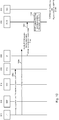
- FIG. 3 shows an example of an LTE network 300.
- the network comprises a user equipment (UE) 302, an eNodeB 304, and an evolved network core (EPC) 306.
- the EPC connects to an external packet data network 308, which in the example illustrated here is the internet.
- the UE may be any suitable type of device capable of participating in wireless communications.
- the UE could be, for example, a mobile phone, smartphone, laptop, PC, tablet, etc.
- the eNodeB 304 is an example of a base station and operates to connect the UE to the EPC 306.
- a radio bearer 120 provides a virtual connection between the UE 302 and the eNodeB 304.
- An S1 bearer provides a virtual connection between the eNodeB 304 and the EPC 306.
- the EPC comprises a number of components.
- these are: a mobility management entity (MME) 310; a serving gateway (SGW) 314; a packet data network gateway (PGW) 318; a policy charging and rules function (PCRF) unit 316 and a home subscriber server (HSS) 312.
- MME mobility management entity
- SGW serving gateway
- PGW packet data network gateway
- PCRF policy charging and rules function
- HSS home subscriber server
- Each of these components may be referred to herein as nodes.
- the MME 310 is shown in more detail and comprises a communications interface 320; a predictive dedicated bearer data store 322; a computation unit 324, a communications module 328 and optionally a timer 326.
- the MME 310 operates to process the signalling between the UE 302 and the EPC 306.
- the MME 310 also operates to select an SGW for a UE during an initial attachment, and to select a PGW.
- the SGW 314 is responsible for controlling handovers of the UE 302 to neighbouring eNodeBs.
- the SGW 314 may also retain information on the bearers when a UE is an idle state. It can buffer downlink data while the MME 310 operates to re-establish a bearer.
- the SGW 314 also functions as a router between the eNodeB 304 and the PGW 318.
- the PGW 318 operates to provide connectivity between the UE 302 and the external PDN 308. It is the point of entry to or exit from the LTE network of data packets for the UE 302.
- the HSS 312 contains subscription data for users of the network. It may store information about the PDN's a UE can connect to. The HSS may also store the identity of the MME to which the UE is currently attached, or registered.
- the PCRF 316 performs policy control and decision making. It can provide QoS authorisation for UE's participating in communication sessions and manage data flows in accordance with a user's subscription profile.
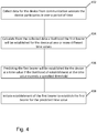
- Figure 4 outlines steps of a process to establish a first bearer that transports data packets of a second bearer between two nodes of the network 300. Both the first bearer and the second bearer have as their endpoints nodes within the LTE network 300.
- the first bearer is the E-RAB bearer, which transports data packets of the EPS bearer (the 'second bearer') between two nodes of the LTE network (the UE 302 and the SGW 314).
- data from communication sessions the device participates in is collected over a period of time.
- the data is used to profile the communication sessions the device participates in over the period of time. More specifically, the data may be used to profile requests to establish an E-RAB bearer to support a communication session the device is participating in.
- data is collected to profile the establishment of E-RABs used by the device (i.e. established to support a communication session the device is participating in) over a period of time.
- the device may be said to be participating in a communication session when it is connected to a PDN.
- Step 402 is performed by the MME 310.
- the MME 310 may only collect data for certain UE's in the network 300. For example, the MME 310 may collect data only for UE's that have subscribed to a particular service provisioned by the network 300.
- the MME 310 may identify UEs it is to collect session data for through a flag communicated by the UEs. For clarity, this flag may be referred to herein as a predictive E-RAB (pERAB) flag.
- pERAB predictive E-RAB
- the MME 310 collects session data for UE's tagged by the pERAB flag.
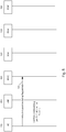
- the pERAB may conveniently be provided in a new field of the Attach Request message communicated from the UE to the MME. This message may be a request for attachment to the network 300, as illustrated in figure 5 .
- the UE 302 communicates an Attach Request message 502 to the MME to request attachment to the network.
- the message 502 is modified to include a field for the pERAB flag.
- FIG 5 shows the attach request being sent directly from the UE 302 to the MME 310, in practice the attach request may be routed from the UE 302 to the MME 310 via the eNodeB 304.
- the UE 302 may communicate the Attach Request message (containing the E-RAB flag) to the eNodeB 304.
- the Attach Request message may further include an identification of the UE 302, such as the International Mobile Subscriber Identity (IMSI).
- IMSI International Mobile Subscriber Identity
- the Attach Request message may include additional information, for example as specified in the 3GPP Technical Specification (TS) 23.401.
- the eNodeB 304 forwards the Attach Request message to the MME 310.
- the message may be forwarded to the MME 310 in a control message, or Initial UE message.
- the remainder of the attach procedure may proceed in its normal fashion, e.g. as outlined in TS 23.401 section 5.3.2.1).
- the MME 310 may receive the Attach Request message 502 through its communications interface 320. The received message may then be sent to the data store 322.
- the data store 322 may identify from the received message that the pERAB flag for the UE 302 is set. In other words, the data store 322 may determine from the device identification identifying the UE 302 (e.g. the IMSI) and the set pERAB flag within the Attach Request Message, that session data is to be collected for communication sessions the UE 302 participates in. Thus, the MME 310 collects data for subsequent communication sessions the UE 302 participates in following the initial attachment to the network.
- the information collected by the MME 310 for each of the UE's communication sessions could include one or more of: a) identification information for the UE 302 (e.g. the UE's IMSI); b) timing information indicating the time an E-RAB bearer was established to support the communication session the UE 302 was participating in; c) location information indicating: i) the network cell the UE 302 is located in when the communication session was established, or ii) the network cell the UE 302 was located in at the time the E-RAB bearer was established; d) application information identifying the type of application running on the UE 302 the E-RAB bearer is being used for (e.g. the type of network data communicated as part of the session being supported by the E-RAB), such as VoIP, video calling, video streaming, gaming etc.
- identification information for the UE 302 e.g. the UE's IMSI
- the timing information may be in the form of a timestamp.
- the timing information may identify a time of day at which the E-RAB was established.
- the timing information may optionally additionally identify a day of the week at which the E-RAB was established, and/or the calendar date on which the E-RAB was established.
- the 'time' the E-RAB was established may refer to a time of day, or optionally a time of day and day of week, or a time and date.
- the MME 310 may collect, for each communication session the UE 302 participates in over some period of time: the time the E-RAB bearer was established to support the communication session; a location of the network cell the UE 302 was located in at the time the E-RAB was established; and optionally information characterising the type of application the established E-RAB bearer was used for.
- the collected data is used to estimate, for one or more different time values, the likelihood an E-RAB will be established to support a communication session for the UE 302 at that time value.
- the likelihood may take the form of a calculated probability. That is, for one or more different time values (e.g. a time of day; a time of day and day of week, etc.) a likelihood, or probability, that an E-RAB will be established for the UE 302 at that time value is calculated.
- Step 404 may be performed by the computation unit 324 of the MME 310 (shown in figure 3 ).
- the computation unit 324 may perform a predictive algorithm to calculate the probabilities the E-RAB will be established at one or more different times.
- the estimated likelihoods may be calculated from the data collected for each of the communication sessions the UE 302 participates in over the time period.
- the computation unit 324 may refine its estimated likelihood each time data additional data is collected for the UE 302, i.e. each time additional data is collected by the data store 322 for a communication session the UE 302 is participating in. In other words, the computation unit 324 may update its estimated likelihood each time data for a new communication session the device participates in is recorded in the data store 322.
- the computation unit 324 may calculate the likelihood that the E-RAB will be established for the UE 302 within a particular time interval. That time interval could be for example be of the order of minutes, e.g. a 5 minute interval, a 10 minute interval etc. The calculated likelihood for the time interval may then be ascribed to a particular time within that time interval. That time value may conveniently be the beginning of the time interval.
- the estimated likelihood an E-RAB will be established for the UE 302 within a specific time interval may be calculated as a function of: i) the number of times an E-RAB was established for the UE 302 within the specific time interval for each day the session information was collected and recorded; and ii) the number of days over which the session information was collected and recorded.
- the estimated likelihood an E-RAB will be established for the UE 302 within the time interval between 10:00am and 10:10am may be calculated as 0.7, or 70%.
- the estimated likelihood for the time interval may then be ascribed to the time value defining the beginning of the time interval (in this example, 10:00am).
- the network cell location is not taken into account in the predictive calculations performed by the computation unit 324. That is, the estimated likelihood of E-RAB establishment may be calculated using only the timing information in the data store 322, and excluding the location information. This may be useful for estimating when E-RAB bearers are likely to be established for UE's that use regularly use the same services at similar times for each day, but from different locations.
- the estimated likelihood an E-RAB will be established may be calculated by the computation unit 324 additionally in dependence on the location of the UE 302 within the network. That is, the calculation unit 324 may use the location information recorded in the data store 322 to estimate: i) the likelihood an E-RAB will be established for the UE 302 at one or more time values; and ii) the network cell that E-RAB will be established in for the UE 302 (i.e., the network cell the device will be located in when that E-RAB is established).
- the estimated likelihood an E-RAB will be established may additionally be calculated by the computation unit 324 in dependence on the type of application, or service, running on the UE 302. That is, the computation unit 324 may use the information recorded in the data store 322 to estimate: i) the likelihood an E-RAB will be established for the UE 302 at one or more time values; and ii) the type of application, or service, running on the UE 302 that E-RAB will be established for.
- the computation unit 324 may estimate: i) the likelihood an E-RAB will be established for the UE 302 at one or more time values; and ii) the network cell that E-RAB will be established in for the UE 302; and iii) the type of application, or service, running on the UE 302 that E-RAB will be established for.
- the computation unit 324 may predict that the E-RAB bearer will be established for the UE 302 at that time value (step 406). That time value may be referred to herein as a predicted time value.
- the computation unit 324 may additionally predict which network cell the E-RAB will be established in, and/or the application or service running on the UE 302 the E-RAB will be established for. That is, the computation unit 324 may predict the network cell the E-RAB will be established in at the predicted time value.
- Step 406 may be implemented by decision logic. That is, the computation unit may make a prediction that the E-RAB will be established at a time value if the associated likelihood exceeds the specified threshold, and not make a prediction if the likelihood is below the specified threshold.
- the specified threshold may be set by the MME 310.
- the value of the threshold may depend on the associated time value. For example, a lower threshold may be associated with 'peak' time values (e.g. time values at which the network is expected to be particularly busy). During these time values it may be more important from a performance perspective to have the E-RAB established in time for its use by the UE 302. It may therefore be desirable to lower the threshold to reduce the risk of a bearer not being established for the UE 302 when one was needed.
- the values of the threshold may alternatively or in addition depend on the associated type of service the E-RAB will be established for. For example, certain types of service (e.g. gaming) are more time-critical than others (e.g. web browsing). It may therefore be preferable to have a lower prediction threshold for the more time-critical services to reduce the risk of a bearer for that service not being established for the UE 302 when one was needed.
- the computation unit 324 estimates the likelihood an E-RAB will be established for the UE 302 at one or more time values (and optionally, also the network cell the E-RAB will be established in and/or the service running on the UE 302 the E-RAB will be established for). If any of those estimated likelihoods exceed a specified threshold, then at step 406 the computation unit 324 may predict that an E-RAB will be established at the corresponding time value(s) (and optionally, predict the network cell the E-RAB will be established in and/or the service running on the UE 302 the E-RAB will be established for).
- the MME 310 initiates the establishment of an E-RAB for the UE 302 so that the E-RAB is established by the time value at which the likelihood exceeds the specified threshold (i.e. by the predicted time value). That is, the MME 310 initiates the establishment of the E-RAB at some time prior to the predicted time value so that the E-RAB is established by the predicted time value.
- the MME 310 may initiate the establishment some specified time period before the predicted time value. This time period may be dependent on the average or typical time taken to establish an E-RAB.
- the MME 310 initiates the establishment of the E-RAB in that network cell. That is, the MME 310 initiates the establishment of the E-RAB so it is established at the predicted time value and in the predicted network cell (i.e. the network cell the first bearer is predicted to be established in at the predicted time value).
- the establishment of the E-RAB is illustrated in figure 6 .
- FIG. 6 shows a call flow for UE requested bearer resource modification.
- the UE 302 sends a bearer resource modification request 602 to the MME 310.
- the MME 310 initiates the establishment of an E-RAB at a predicted time value TP.
- the MME 310 communicates a bearer resource command message 606 to the SGW 314. This message may be sent by the communications module 328 via the interface 320.
- the SGW 314 In response to receiving the command 606, the SGW 314 sends a return 'create bearer request' message 608 back to the MME 310. This contrasts with the conventional call flow depicted in 3GPP TS 23.401, where the SGW 314 sends the bearer resource command to the PGW 318. In accordance with the present disclosure, the SGW 314 answers the bearer resource command 606 to establish the E-RAB.
- the MME 310 In response to receiving the create bearer request 608 from the SGW 314, the MME 310 communicates an E-RAB setup request message 610 to the eNodeB 304. In response to receiving this message, the eNodeB 304 establishes the radio bearer with the UE 302. This is done through the exchange of RRC reconfiguration messages 612 and 614. Once establishment of the radio bearer is complete, the eNodeB 304 communicates an E-RAB setup response message 616 back to the MME 310. In response, the MME 310 communicates a create bearer response message 618 back to the SGW 314 to complete the establishment of the E-RAB between the UE 302 and the SGW 314.
- the call flow may then continue with the exchange of further messages denoted generally at 620 (e.g. as per 3GPP TS 25.401).
- the MME 310 may be configured to initiate deactivation of the E-RAB established at step 408 in response to determining that the bearer is not used by the UE 302 within a specified time period tmax of its establishment. This can conveniently free up resources of the network if it is determined the UE 302 is in an idle mode.
- the MME 310 may start timer 326 when the E-RAB is established. If the MME 310 detects that the E-RAB has not been used by the UE 302 upon expiry of the waiting time tmax, it initiates deactivation of the E-RAB. The timer 326 may then be reset.
- Figure 7 is a call flow illustrating the deactivation of the E-RAB established from predictions made at step 404 from the session data collected at step 402.
- Figure 7 is based on the call flow illustrating PGW-initiated bearer deactivation per 3GPP TS 23.401, but with some modifications which will be explained below.
- the PCRF 316 sends an IP-CAN session modification message 702 to the PGW 318.
- the PGW 318 sends a 'delete bearer request' message 704 to the SGW 314.
- the MME 310 receives from the SGW 314 a delete bearer request message 706.
- Step 4a is performed when bearer deactivation is neither due to Idle State Signalling Reduction (ISR) deactivation or handover to non-3GPP accesses.
- Step 4b is performed if the UE 302 is in an idle state and the reason for releasing the bearer is because of a request for reactivation.
- ISR Idle State Signalling Reduction
- Step 4bii is a new step performed by the MME 310 in accordance with the present disclosure.
- the MME 310 determines that the established E-RAB has not been used by the UE 302 within the time period tmax of its predicted time. Thus, the UE 302 may be in an idle state.
- the MME 310 sends a deactivate bearer request message 708 to the eNodeB 304 to initiate deactivation of the E-RAB. This message may be sent by the communications module 328 via the interface 320.
- the eNodeB 304 releases the radio bearer through messages 710, 712 and 714.
- the call flow then continues through the exchange of messages denoted generally at 716 in accordance with 3GPP TS 23.401.
- the MME 310 communicates a deactivate bearer request message 708 to the eNodeB 304 to initiate deactivation of the established E-RAB in response to determining the E-RAB has not been used by the UE 302 within a maximum time period tmax of its establishment at step 406.
- the above examples describe an approach for predicting a time at which an E-RAB will be established for a UE 302 (and potentially the network cell it will be established in), and initiating establishment of the E-RAB at that predicted time (and optionally in the predicted network cell). It will be appreciated that the above-described techniques could be equivalently applied to predict a time at which a radio bearer will be established for a UE, and initiating establishment of the radio bearer at that predicted time.
- the data store 322 may record data from the communication sessions the UE 302 participates in to profile over a time period requests to establish a radio bearer for the UE 302.
- data is collected to profile the establishment of radio bearers used by the UE 302.
- the data collected by the MME 310 for each of the UE's communication sessions may include timing information indicating the time the radio bearer was established to support that communication session.
- the computation unit 324 may then estimate the likelihood a radio bearer will be established for the UE 302 at one or more different time values, e.g. using any of the techniques described above with reference to step 404.
- the MME 310 can initiate establishment of the radio bearer at that time value. The MME 310 may do this by sending a bearer resource command message 606 to the SGW 314 as described above with reference to figure 6 .
- the MME 310 may also estimate from the collected data the network cell the radio bearer will be established in for the UE 302, and/or the service running on the UE 302 that radio bearer will be established for. The MME 310 can then initiate establishment of the radio bearer in that estimated network cell.
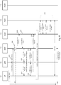
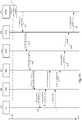
- FIG. 8 shows a further example of an LTE network 800.
- the network comprises a user equipment (UE) 802, an eNodeB 804, and an evolved network core (EPC) 806.
- the EPC 806 connects to an external packet data network 808, which in the example illustrated here is the internet.
- the EPC 806 comprises: a mobility management entity (MME) 810; a serving gateway (SGW) 814; a packet data network gateway (PGW) 818; a policy charging and rules function (PCRF) unit 816 and a home subscriber server (HSS) 812.
- MME mobility management entity
- SGW serving gateway
- PGW packet data network gateway
- PCRF policy charging and rules function
- HSS home subscriber server
- AF application function
- the AF is a component external to the EPC 806 and operates to provide session and media related information to the PCRF 816.
- the MME 810 may be a standard MME node (i.e. it may not include the components of the MME 310).
- the PCRF 816 is shown in more detail and comprises a communications interface 820; a predictive dedicated bearer data store 822; a computation unit 824, a communications module 830 and optionally a timer 826.
- FIG. 9 outlines steps of a process to establish a dedicated bearer that transports data packets between two nodes of the network 800.
- the dedicated bearer has as its endpoints nodes within the LTE network 800.
- the dedicated bearer is an EPS bearer that has as its endpoints the UE 802 and PGW 818.
- data from communication sessions the UE 802 participates in is collected over a period of time.
- the data is used to profile the communication sessions the device 802 participates in over the period of time. More specifically, the data may be used to profile requests to establish a dedicated bearer to support a communication session the UE 802 is participating in. In other words, data is collected to profile the establishment of dedicated bearers used by the device 802 (i.e. established to support a communication session the device is participating in) over a period of time.
- Step 902 is performed by the PCRF 816.
- the PCRF 816 may only collect data for certain UE's in the network 800. For example, the PCRF 816 may collect data only for UE's that have subscribed to a particular service provisioned by the network.
- the PCRF 816 may identify UE's it is to collect session data for through a flag communicated to the PCRF 816. For clarity, this flag may be referred to as a predictive dedicated bearer (PDB) flag.
- PDB predictive dedicated bearer
- the PDB flag may conveniently be provided in a field of a message received at the PCRF 816 from the AF 828 to modify the session information. This is illustrated in figure 10 .
- Figure 10 shows at 1002 the UE 802 requesting attachment to the network and the establishment of a PDN session, including bearer creation. Following creation of the session, user data plane traffic is communicated between the UE 802 and the network, shown at 1004.
- the AF sends a modify session information message 1006 to the PCRF 816.
- This message indicates the PCRF 816 is to store updated, or modified, information for the session the UE 802 is participating in. Included within that message is the PDB flag. Also included within the message 1006 is an identification of the UE 802, such as the International Mobile Subscriber Identity (IMSI).
- IMSI International Mobile Subscriber Identity
- the PCRF 816 receives the modify session information message 1006 through its communication interface 820.
- the received message may then be sent to the data store 822.
- the data store 822 may identify from the received message that the PDB flag for the UE 802 is set. In other words, the data store 822 may determine from the device identification identifying UE 802 (e.g. the IMSI) and the set PDB flag within the modify session information message from the AF 828 that session data is to be collected for communication sessions device 802 participates in.
- the PCRF 816 collects data for communication sessions after detecting the PDB flag. This is illustrated in figure 10 at block 1008.
- the information collected by the PCRF 816 for each of the UE's communication sessions could include one or more of: a) identification information for the UE 802 (e.g. the UE's IMSI); b) timing information indicating the time a dedicated bearer was established to support the communication session the UE 802 was participating in; c) location information indicating: i) the network cell the UE is located in when the communication session was established, or ii) the network cell the UE was located in at the time the dedicated bearer was established; d) application information identifying the type of application running on the UE 802 the dedicated bearer is being used for (e.g. the type of network data communicated as part of the session being supported by the dedicated bearer), such as VoIP, video calling, video streaming, gaming etc.
- identification information for the UE 802 e.g. the UE's IMSI
- timing information indicating the time a dedicated bearer was established to support the communication session the UE 802 was participating in
- location information indicating:
- the timing information may be in the form of a timestamp.
- the timing information may identify a time of day at which the dedicated bearer was established.
- the timing information may optionally additionally identify a day of the week at which the dedicated bearer was established, and/or the calendar date on which the dedicated bearer was established.
- the 'time' the dedicated bearer was established may refer to a time of day, or optionally a time of day and day of week, or a time and date.
- the PCRF 816 may collect, for each communication session the UE 802 participates in over some period of time: the time the dedicated bearer was established to support the communication session; a location of the network cell the UE 802 was located in at the time the dedicated bearer was established; and optionally information characterising the type of application the established dedicated bearer was used for.
- the collected data is used to calculate, for one or more different time values, the likelihood a dedicated bearer will be established to support a communication session for the UE 802 at that time value.
- the likelihood takes the form of a calculated probability. That is, for one or more different time values (e.g. a time of day; a time of day and day of week, etc.) a likelihood, or probability, that dedicated bearer will be established for the UE 802 at that time value is calculated.
- Step 904 may be performed by the computation unit 824 of the PCRF 816 (shown in figure 8 ).
- the computation unit 824 may perform a predictive algorithm to calculate the probabilities the dedicated bearer will be established at one or more different times.
- the estimated likelihoods are calculated from the data collected for each of the communication sessions the UE 802 participates in over the time period.
- the computation unit 824 may refine its estimated likelihood each time data additional data is collected for the UE 802, i.e. each time additional data is collected by the data store 822 for a communication session the UE 802 is participating in. In other words, the computation unit 824 may update its estimated likelihood each time data fnr a new communication session the device participates in is recorded in the data store.
- the computation unit 824 may calculate the likelihood that the dedicated bearer will be established for the UE 802 within a particular time interval. That time interval could be for example be of the order of minutes, e.g. a 5 minute interval, a 10 minute interval etc. The calculated likelihood for the time interval may then be ascribed to a particular time within that time interval. That time value may conveniently be the beginning of the time interval.
- the estimated likelihood a dedicated bearer will be established for the UE 802 within a specific time interval may be calculated as a function of: i) the number of times an dedicated bearer was established for the UE 802 within the specific time interval for each day the session information was collected and recorded; and ii) the number of days over which the session information was collected and recorded.
- the estimated likelihood a dedicated bearer will be established for the UE 802 within the time interval between 10:00am and 10:10am may be calculated as 0.7, or 70%.
- the estimated likelihood for the time interval may then be ascribed to the time value defining the beginning of the time interval (in this example, 10:00am).
- the network cell location is not taken into account in the predictive calculations performed by the computation unit 824. That is, the estimated likelihood of dedicated bearer establishment may be calculated using only the timing information in the data store 822, and excluding the location information. This may be useful for estimating when dedicated bearers are likely to be established for UE's that use regularly use the same services at similar times for each day, but from different locations.
- the estimated likelihood a dedicated bearer will be established may be calculated by the computation unit 824 additionally in dependence on the location of the UE 802 within the network. That is, the calculation unit 824 may use the location information recorded in the data store 822 to estimate: i) the likelihood dedicated bearer will be established for the UE 802 at one or more time values; and ii) the network cell that the dedicated bearer will be established in for the UE 802 (i.e. the network cell the device will be located in when that dedicated bearer is established).
- the estimated likelihood a dedicated bearer will be established may additionally be calculated by the computation unit 824 in dependence on the type of application, or service, running on the UE 802. That is, the computation unit 824 may use the information recorded in the data store 822 to estimate: i) the likelihood a dedicated bearer will be established for the UE 802 at one or more time values; and ii) the type of application, or service, running on the UE 802 that dedicated bearer will be established for.
- the computation may estimate: i) the likelihood a dedicated bearer will be established for the UE 802 at one or more time values; and ii) the network cell that dedicated bearer will be established in for the UE 802; and iii) the type of application, or service, running on the UE 802 that dedicated bearer will be established for.
- the computation unit 824 may predict that the dedicated bearer will be established for the UE 802 at that time value (step 906).
- the computation unit 824 may additionally predict which network cell the dedicated bearer will be established in, and/or the application or service running on the UE 802 the dedicated bearer will be established for.
- Step 906 may be implemented by decision logic. That is, the computation unit 824 makes a prediction that the dedicated bearer will be established at a time value if the associated likelihood exceeds the specified threshold, and not make a prediction if the likelihood is below the specified threshold.
- the specified threshold may be set by the PCRF 816.
- the value of the threshold may depend on the associated time value. For example, a lower threshold may be associated with 'peak' time values (e.g. time values at which the network is expected to be particularly busy). During these time values it may be more important from a performance perspective to have the dedicated bearer established in time for its use by the UE 802. It may therefore be desirable to lower the threshold to reduce the risk of a bearer not being established for the UE 802 when one was needed.
- the values of the threshold may alternatively or in addition depend on the associated type of service the dedicated bearer will be established for. For example, certain types of service (e.g. gaming) are more time-critical than others (e.g. web browsing). It may therefore be preferable to have a lower prediction threshold for the more time-critical services to reduce the risk of a bearer for that service not being established for the UE 802 when one was needed.
- the computation unit 824 estimates the likelihood a dedicated bearer will be established for the UE 802 at one or more time values (and optionally, also the network cell the dedicated bearer will be established in and/or the service running on the UE 802 the dedicated bearer will be established for). If any of those estimated likelihoods exceed a specified threshold, then at step 906 the computation unit 824 predicts that a dedicated bearer will be established at the corresponding time value(s) (and optionally, predict the network cell the dedicated bearer will be established in and/or the service running on the UE 802 the dedicated bearer will be established for).
- the PCRF 816 initiates the establishment a dedicated bearer for the UE 802 so that the dedicated bearer is established by the time value at which the likelihood exceeds the specified threshold (i.e. by the predicted time value). That is, the PCRF 816 initiates the establishment of the dedicated bearer at some time prior to the predicted time value so that the dedicated bearer is established by the predicted time value.
- the PCRF 816 may initiate the establishment some specified time period before the predicted time value. This time period may be dependent on the average or typical time taken to establish a dedicated bearer.
- the computation unit 824 additionally estimates the network cell the dedicated bearer will be established in for the UE 802, then at step 406 the PCRF 816 initiates the establishment of the dedicated in that network cell. That is, the PCRF 816 initiates the establishment of the dedicated bearer so it is established the predicted time value and in the predicted network cell.
- the establishment of the dedicated bearer is illustrated in figure 11 .
- Figure 11 shows a call flow for dedicated bearer activation.
- the call flow is based on the flow for dedicated bearer activation in 3GPP TS 23.401, but with some modifications explained below.
- the PCRF 816 initiates establishment of a dedicated bearer at a predicted time value Tp. This step is not included within the conventional call flow for dedicated bearer establishment.
- the PCRF 816 sends a session modification message 1104 to the PGW 818.
- Message 1104 may be referred to as an IP-CAN Session Modification message, or a QoS policy message. This message may be sent by the communications module 830 via the communications interface 820.
- a create bearer request message 1106 is communicated from the PGW 818 to the SGW 814, and in response from the SGW 814 to the MME 810 (message 1108).
- the MME 810 then operates to establish the radio bearer between the UE 802 and eNodeB 804 through the exchange of messages denoted generally at 1110 (steps 4 to 7).
- the MME 810 then communicates a create bearer response message 1112 from the MME 810 to the SGW 814, and the SGW 814 communicates the create bearer response message 1114 to the PGW 818.
- the PGW 818 communicates the session modification complete message 1116 to the PCRF 816 to complete establishment of the dedicated bearer.
- the message 1116 may also be referred to as an IP-CAN Session Modification.
- the PCRF 816 may be configured to initiate deactivation of the dedicated bearer established at step 908 in response to determining that the dedicated bearer is not used by the UE 802 within a specified time period tmax of its establishment by the PCRF 816. This can conveniently free up resources of the network if it is determined they are not being used by the UE 802.
- the PCRF 816 may start timer 826 when the dedicated bearer is established (e.g. at time Tp). If the PCRF 816 detects that the dedicated bearer has not been used by the UE 802 upon expiry of the waiting time tmax, it initiates deactivation of the dedicated bearer. The timer may then be reset.
- Figure 12 is a call flow illustrating the deactivation of the dedicated bearer established from predictions made at step 904 from the session data collected at step 902.
- Figure 12 is based on the call flow illustrating dedicated bearer deactivation per 3GPP TS 23.401, but with some modifications which will be explained below.
- Step 1a is a new step performed by the PCRF 816 in accordance with the present disclosure.
- the PCRF 816 determines that the established dedicated bearer has not been used by the UE 802 within the time period tmax of its predicted time. Thus, the UE 802 may be in an idle state.
- the PCRF 816 sends a session modification request message 1204 to the PGW 818.
- the session modification request message indicates the dedicated bearer is to be deactivated. This message may be sent by the communications module 830 through the interface 820.
- Message 1204 causes the PGW 818 to send a delete bearer request message 1206 to the SGW 814, which in turn communicates the delete bearer request message 1208 to the MME 810.
- the call flow then continues through the exchange of messages denoted generally at 1210 (steps 4 to 11) in accordance with 3GPP TS 23.401.
- the above-described examples illustrate techniques for predicting a time when a bearer (e.g. a radio, E-RAB or dedicated EPS bearer) will be used by a UE within a communication network, and initiating the establishment of the bearer so that it can be established at the predicted time (and optionally network cell location).
- a bearer e.g. a radio, E-RAB or dedicated EPS bearer
- These approaches can enhance the behaviour of the network by reducing the delay experienced by the UE waiting for a required bearer to be established.
- the approaches described herein enable a bearer to be established for when it is needed by the UE using prediction information calculated from recorded session data.
- the above examples have been described in the context of LTE networks for the purposes of illustration, but it will be appreciated that the techniques herein could equally be applied to other networks implementing bearers.
Description
- This invention relates to techniques for establishing bearers within a wireless communication network based on predictive techniques.
- In wireless communication networks, bearers can be used to identify traffic flows (e.g. IP packet flows) between nodes of the network that have a common quality of service (QoS) requirement. That is, a bearer is an IP packet flow with a defined QoS between two nodes of a network. A bearer may be viewed as a virtual connection between two nodes of the network.
- An example of a communication network that uses bearers is the Long Term Evolution (LTE) network.
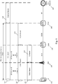
Figure 1 schematically illustrates the bearers for an LTE network. - An LTE network typically includes a device (e.g. a user equipment (UE)) 102; a base station 104 (referred to as an eNodeB); a serving gateway (SGW) 106; and a packet data network (PDN) gateway (PGW) 108. The SGW 106 and the PGW form part of the evolved packet core (EPC). The EPC core may contain additional components not shown in
figure 1 for the purposes of clarity. The LTE network connects thedevice 102 to an external packet data network (PDN) 110. - Evolved Packet System (EPS)
bearers 112 are a virtual connection between the UE 102 and the PGW 108. The EPS bearer identifies data (e.g. IP packets) communicated between these two endpoints (i.e. data sent from the UE 102 to the PGW 108 and data sent from the PGW 108 to the UE 102) with specific QoS attributes/requirements. In other words, the EPS bearer uniquely identifies traffic flows (e.g. data packets) that have a common QoS requirement between the UE 102 and the PGW 108. The EPS bearer is a bearer of the LTE network; that is, it connects two endpoints, or nodes (the UE 102 and PGW 108) that are within the LTE network.External bearer 114 is a virtual connection between thePGW 108 of the LTE network and the externalpacket data network 110. - The EPS bearer provides the PDN connectivity service to the UE 102. EPS bearers are typically created on a per-PDN basis; that is, a set of EPS bearers will be established for each PDN the UE 102 is connected to. This is illustrated schematically in
figure 2 . - In the example shown in
figure 2 , the UE 102 is connected to twopacket data networks Network 204 is shown as the internet. It will be appreciated that these examples have been chosen for the purposes of illustration only. - A first set of
EPS bearers 206 provide a virtual connection between the UE 102 and the first PDN 202; and a second set ofEPS bearers 208 provide a virtual connection between the UE 102 and thesecond PDN 204. - In some instances, the UE 102 may communicate multiple different types of data over the network, each with its own QoS requirements. For example, the UE 102 may be running multiple applications at a given time, each having different QoS requirements. To provide some examples, the UE 102 may be concurrently communicating VoIP data and web-browsing data. Typically, VoIP data has higher QoS requirements than web-browsing data in some aspects (e.g. lower acceptable delay times), but lower QoS requirements in other aspects (e.g. packet loss rate). To support the communication of data having different QoS requirements, different EPS bearer types can be set up, each associated with different type of QoS.
- EPS bearers can be broadly classified into two types: default bearers (e.g. 2061 and 2081) and dedicated bearers (e.g. 2062,3 and 2082). Default bearers are established when a UE attaches to the network, and remain established for the duration of the UE's PDN connection. Dedicated bearers may be established at any time subsequent to the establishment of the default bearer. Dedicated bearers may be established to support communication sessions with specific QoS requirements. Dedicated bearers may be of different types, each associated with a respective QoS.
- Referring back to
figure 1 , it can be seen that EPS bearers cross multiple communication interfaces of the network. That is, the EPS bearers cross multiple nodes of the network. Between a given pair of nodes, the EPS bearer maps onto a lower layer bearer. In particular, the EPS bearer maps to an E-UTRAN Radio Access Bearer (E-RAB)bearer 116 between the UE 102 and SGW 106. In other words, the E-RABbearer 116 has two endpoints, the UE 102 and the SGW 106. The EPS bearer also maps to an S5/S8 bearer 118 between the SGW 106 and the PGW 108 (i.e., the endpoints of the S5/S8 bearer are the SGW 106 and the PGW 108). - Thus, the
EPS bearer 112 consists of the E-RAB bearer and the S5/S8 bearer. The EPS bearer may be referred to as the concatenation of the E-RAB bearer and the S5/S8 bearer. - The E-RAB
bearer 116 connects the UE 102 to the SGW 106 (more specifically, it connects the UE 102 to the eNodeB 104, and the eNodeB 104 to the SGW 106). The E-RAB transports the data packets of the EPS bearer between the UE 102 and the SGW 106. - The S5/S8 bearer connects the SGW 106 to the PGW 108, and transports the data packets of the EPS bearer between the SGW 106 and the PGW 108.
- The E-RAB bearer maps to a
radio bearer 120 andS1 bearer 122 between the UE 102 and SGW 106. In more detail, the E-RAB bearer maps to theradio bearer 120 between the UE 102 and eNodeB 104, and to the S1 bearer between the eNodeB 104 and SGW 106. Thus, the E-RAB bearer consists of theradio bearer 120 andS1 bearer 122. It may be referred to as the concatenation of theradio bearer 120 and theS1 bearer 122. The radio bearer transports the data packets of the E-RAB bearer between the UE 102 and the eNodeB 104, and the S1 bearer transports the data packets of the E-RAB bearer between the eNodeB 104 and the SGW 106. - There is typically a delay in establishing bearers for a communication session. For example, dedicated bearers are not established until after a default bearer has been established, resulting in a potential delay and non-guaranteed QoS until the dedicated bearer is established. Other bearers (such as the E-RAB or radio bearers) may be particularly susceptible to congestion, meaning there can also be a delay in trying to establish these bearers when initiating a communication session. These delays may be undesirable for a user of the UE, and in some cases may negatively impact the performance of the UE, particularly in cases when the UE is running time-sensitive applications, such as gaming, or remote diagnostics.
-
US20070064676 discloses a method of controlling the establishment of a packet switched bearer or bearers for carrying multimedia information between two or more user terminals during a circuit switched voice call, the method comprising at setup of or during the voice call, predicting at one of the user terminals the likelihood that multimedia information will be exchanged between the user terminals during the voice call based upon properties stored at that terminal for the or each other user or user terminal, and automatically establishing said bearer or not, based upon the prediction. - 3GPP TS 23.401 V15.3.0 (dated March 2018) from the 3rd Generation Partnership Project, Technical Specification Group Services and System Aspects, General Packet Radio Service (GPRS) enhancements for Evolved Universal Terrestrial Radio Access Network (E-UTRAN) access, discloses background principles regarding the establishment of bearers in 3GPP networks.
- According to one aspect of the present invention there is provided a method of establishing bearers for a device in a wireless communication network, comprising:
- collecting for the device data over a period of time from communication sessions the device participates in, at least some of the communication sessions being supported by a default bearer and a dedicated bearer;
- calculating from the collected data a likelihood a dedicated bearer will be established for the device at one or more different times values, and predicting the dedicated bearer will be established for the device at a time value if the likelihood of establishment at that time value exceeds a specified threshold; and
- initiating establishment of the dedicated bearer to establish the dedicated bearer for the predicted time value.
- The method may further comprise receiving at a node of the network a request to modify session information, the request including an identification flag indicating data from communication sessions the device participates in is to be collected for the device, wherein data for the device is collected at the module following receipt of the identification flag.
- The node may be a policy and charging rules function (PCRF) node.
- The collected data may comprise timing data indicating time values the dedicated bearer is established for the device.
- The collected data may further comprise location data indicating a network cell of the communication network the dedicated bearer is established in for the device.
- The calculating step may comprise calculating: (i) a likelihood the dedicated bearer will be established for the device at one or more different time values and (ii) the network cell the dedicated bearer will hp established in for thp device.
- The initiating step may comprise initiating establishment of the dedicated bearer: (i) to establish the dedicated bearer for the predicted time; and (ii) within the network cell the dedicated bearer is predicted to be established in at the predicted time value.
- The method may further comprise initiating deactivation of the dedicated bearer if it is determined the device has not used the dedicated bearer within a specified time period of the establishment of the dedicated bearer.
- The dedicated bearer may be an EPS bearer.
- According to another aspect of the present invention there is provided an apparatus for establishing bearers for a device within a wireless communication network, comprising:
- a data store configured to collect for the device data over a period of time from communication sessions the device participates in, at least some of the communication sessions being supported by a default bearer and a dedicated bearer;
- a computation module configured to calculate from the collected data a likelihood a dedicated bearer will be established for the device at one or more different times values, and predict the dedicated bearer will be established for the device at a time value if the likelihood of establishment at that time value exceeds a specified threshold; and
- a communications module configured to initiate establishment of the dedicated bearer to establish the dedicated bearer for the predicted time value.
- The present invention will now be described by way of example with reference to the example of
fig. 9 and its description which is according to the invention as defined in the claims.Fig. 1-8 and10-12 and their descriptions do not or do not fully correspond to the invention as defined in the claims and are therefore not according to the invention as defined in the claims and are present for illustration purposes only or to highlight specific aspects or features of the claims. In the drawings: -
Figure 1 shows a schematic illustration of bearers within an LTE network. -
Figure 2 shows a schematic illustration of EPS bearers within an LTE network. -
Figure 3 shows an example of an LTE network in accordance with an example of the present disclosure. -
Figure 4 shows a flowchart of steps for establishing a first bearer using predictive techniques. -
Figure 5 shows a call flow illustrating an attach request for a UE's attachment to a network. -
Figure 6 shows a call flow illustrating the establishment of an E-RAB at a predicted time of use by the UE. -
Figure 7 shows a call flow illustrating the deactivation of the established E-RAB after a specified time period of non-use by the UE. -
Figure 8 shows an example LTE network in accordance with another example. -
Figure 9 shows a flowchart of steps for establishing a dedicated bearer using predictive techniques. -
Figure 10 shows a call flow illustrating the identification of a UE for which session information is to be recorded. -
Figure 11 shows a call flow illustrating the establishment of a dedicated bearer at a predicted time of use by the UE. -
Figure 12 shows a call flow illustrating the deactivation of the established dedicated bearer after a specified time period of non-use by the UE. - The present disclosure is directed to approaches for establishing bearers within a wireless communication network using predictive techniques. The bearers can be established within the network for a device on the basis of predictions made from data collected from communication sessions the device participates in. The predictions estimate the likelihood, or probability, for one or more different times that the device will use the bearer as part of a communication session at that time. If an estimated likelihood that a bearer will be established at a particular time exceeds a specified threshold, establishment of that bearer is initiated so that the bearer is established at that time. By establishing a bearer based on a predicted likelihood of use, the bearer can be established and ready for use for the time it is needed by the device. This may reduce the delay associated within establishing certain types of bearers within the network.
- Two general classes of examples for establishing bearers will be described herein. The first set of examples which are not according to the invention relate to establishing a first bearer that transports data packets of a second bearer between nodes, or components of the network. In these examples, the second bearer comprises the first bearer; in other words, the second bearer is the concatenation of the first bearer and some other third bearer. Put another way, the second bearer is a higher layer bearer than the first bearer/ the first bearer is a lower layer bearer than the second bearer. The first bearer could for example be an E-RAB bearer, or a radio bearer. The second bearer could be an EPS bearer (if the first bearer is an E-RAB bearer), or the second bearer may be an E-RAB bearer (if the first bearer is a radio bearer).
- The second set of examples which are according to the invention relate to establishing a dedicated bearer.
- These examples will now be described in more detail with reference to
figures 3 to 12 . These examples will describe the establishment of bearers in the context of an LTE network. It will be appreciated that this is for the purposes of illustration only, and that the following techniques and approaches can be applied within different types of wireless communication networks that implement bearers. -
Figure 3 shows an example of anLTE network 300. The network comprises a user equipment (UE) 302, aneNodeB 304, and an evolved network core (EPC) 306. The EPC connects to an externalpacket data network 308, which in the example illustrated here is the internet. - The UE may be any suitable type of device capable of participating in wireless communications. The UE could be, for example, a mobile phone, smartphone, laptop, PC, tablet, etc.
- The
eNodeB 304 is an example of a base station and operates to connect the UE to theEPC 306. As described above with reference tofigure 1 , aradio bearer 120 provides a virtual connection between theUE 302 and theeNodeB 304. An S1 bearer provides a virtual connection between theeNodeB 304 and theEPC 306. - The EPC comprises a number of components. In the example shown, these are: a mobility management entity (MME) 310; a serving gateway (SGW) 314; a packet data network gateway (PGW) 318; a policy charging and rules function (PCRF)
unit 316 and a home subscriber server (HSS) 312. Each of these components may be referred to herein as nodes. TheMME 310 is shown in more detail and comprises acommunications interface 320; a predictive dedicatedbearer data store 322; acomputation unit 324, acommunications module 328 and optionally atimer 326. - A brief overview of the components within the
EPC 306 will now be described. - The
MME 310 operates to process the signalling between theUE 302 and theEPC 306. TheMME 310 also operates to select an SGW for a UE during an initial attachment, and to select a PGW. - The
SGW 314 is responsible for controlling handovers of theUE 302 to neighbouring eNodeBs. TheSGW 314 may also retain information on the bearers when a UE is an idle state. It can buffer downlink data while theMME 310 operates to re-establish a bearer. TheSGW 314 also functions as a router between theeNodeB 304 and thePGW 318. - The
PGW 318 operates to provide connectivity between theUE 302 and theexternal PDN 308. It is the point of entry to or exit from the LTE network of data packets for theUE 302. - The
HSS 312 contains subscription data for users of the network. It may store information about the PDN's a UE can connect to. The HSS may also store the identity of the MME to which the UE is currently attached, or registered. - The
PCRF 316 performs policy control and decision making. It can provide QoS authorisation for UE's participating in communication sessions and manage data flows in accordance with a user's subscription profile. - The operation of the network nodes to establish a bearer based on a predicted likelihood of use by the
UE 302 will now be described with reference tofigure 4. Figure 4 outlines steps of a process to establish a first bearer that transports data packets of a second bearer between two nodes of thenetwork 300. Both the first bearer and the second bearer have as their endpoints nodes within theLTE network 300. In accordance with the examples that will now be described, the first bearer is the E-RAB bearer, which transports data packets of the EPS bearer (the 'second bearer') between two nodes of the LTE network (theUE 302 and the SGW 314). - At
step 402, data from communication sessions the device participates in is collected over a period of time. The data is used to profile the communication sessions the device participates in over the period of time. More specifically, the data may be used to profile requests to establish an E-RAB bearer to support a communication session the device is participating in. In other words, data is collected to profile the establishment of E-RABs used by the device (i.e. established to support a communication session the device is participating in) over a period of time. The device may be said to be participating in a communication session when it is connected to a PDN. - Step 402 is performed by the
MME 310. TheMME 310 may only collect data for certain UE's in thenetwork 300. For example, theMME 310 may collect data only for UE's that have subscribed to a particular service provisioned by thenetwork 300. TheMME 310 may identify UEs it is to collect session data for through a flag communicated by the UEs. For clarity, this flag may be referred to herein as a predictive E-RAB (pERAB) flag. Thus, theMME 310 collects session data for UE's tagged by the pERAB flag. - The pERAB may conveniently be provided in a new field of the Attach Request message communicated from the UE to the MME. This message may be a request for attachment to the
network 300, as illustrated infigure 5 . - As shown in
figure 5 , theUE 302 communicates an AttachRequest message 502 to the MME to request attachment to the network. Themessage 502 is modified to include a field for the pERAB flag. Thoughfigure 5 shows the attach request being sent directly from theUE 302 to theMME 310, in practice the attach request may be routed from theUE 302 to theMME 310 via theeNodeB 304. Thus, theUE 302 may communicate the Attach Request message (containing the E-RAB flag) to theeNodeB 304. The Attach Request message may further include an identification of theUE 302, such as the International Mobile Subscriber Identity (IMSI). The Attach Request message may include additional information, for example as specified in the 3GPP Technical Specification (TS) 23.401. TheeNodeB 304 forwards the Attach Request message to theMME 310. The message may be forwarded to theMME 310 in a control message, or Initial UE message. The remainder of the attach procedure may proceed in its normal fashion, e.g. as outlined in TS 23.401 section 5.3.2.1). - Referring to
figure 3 , theMME 310 may receive the AttachRequest message 502 through itscommunications interface 320. The received message may then be sent to thedata store 322. Thedata store 322 may identify from the received message that the pERAB flag for theUE 302 is set. In other words, thedata store 322 may determine from the device identification identifying the UE 302 (e.g. the IMSI) and the set pERAB flag within the Attach Request Message, that session data is to be collected for communication sessions theUE 302 participates in. Thus, theMME 310 collects data for subsequent communication sessions theUE 302 participates in following the initial attachment to the network. - The information collected by the
MME 310 for each of the UE's communication sessions could include one or more of: a) identification information for the UE 302 (e.g. the UE's IMSI); b) timing information indicating the time an E-RAB bearer was established to support the communication session theUE 302 was participating in; c) location information indicating: i) the network cell theUE 302 is located in when the communication session was established, or ii) the network cell theUE 302 was located in at the time the E-RAB bearer was established; d) application information identifying the type of application running on theUE 302 the E-RAB bearer is being used for (e.g. the type of network data communicated as part of the session being supported by the E-RAB), such as VoIP, video calling, video streaming, gaming etc. - The timing information may be in the form of a timestamp. The timing information may identify a time of day at which the E-RAB was established. The timing information may optionally additionally identify a day of the week at which the E-RAB was established, and/or the calendar date on which the E-RAB was established. Thus, the 'time' the E-RAB was established may refer to a time of day, or optionally a time of day and day of week, or a time and date.
- Thus, the
MME 310 may collect, for each communication session theUE 302 participates in over some period of time: the time the E-RAB bearer was established to support the communication session; a location of the network cell theUE 302 was located in at the time the E-RAB was established; and optionally information characterising the type of application the established E-RAB bearer was used for. - Referring back to
figure 4 , and atstep 404 the collected data is used to estimate, for one or more different time values, the likelihood an E-RAB will be established to support a communication session for theUE 302 at that time value. The likelihood may take the form of a calculated probability. That is, for one or more different time values (e.g. a time of day; a time of day and day of week, etc.) a likelihood, or probability, that an E-RAB will be established for theUE 302 at that time value is calculated. - Step 404 may be performed by the
computation unit 324 of the MME 310 (shown infigure 3 ). Thecomputation unit 324 may perform a predictive algorithm to calculate the probabilities the E-RAB will be established at one or more different times. - The estimated likelihoods may be calculated from the data collected for each of the communication sessions the
UE 302 participates in over the time period. Thecomputation unit 324 may refine its estimated likelihood each time data additional data is collected for theUE 302, i.e. each time additional data is collected by thedata store 322 for a communication session theUE 302 is participating in. In other words, thecomputation unit 324 may update its estimated likelihood each time data for a new communication session the device participates in is recorded in thedata store 322. - Because the chances of an E-RAB being established for the
UE 302 at the same time (e.g. to within the same minute) on different days may be relatively low, thecomputation unit 324 may calculate the likelihood that the E-RAB will be established for theUE 302 within a particular time interval. That time interval could be for example be of the order of minutes, e.g. a 5 minute interval, a 10 minute interval etc. The calculated likelihood for the time interval may then be ascribed to a particular time within that time interval. That time value may conveniently be the beginning of the time interval. - The estimated likelihood an E-RAB will be established for the
UE 302 within a specific time interval may be calculated as a function of: i) the number of times an E-RAB was established for theUE 302 within the specific time interval for each day the session information was collected and recorded; and ii) the number of days over which the session information was collected and recorded. As a simple example, if the session information was recorded over a time period of 10 days, and an E-RAB was established for theUE 302 within the time interval between 10:00am and 10:10am on 7 of those days, the estimated likelihood an E-RAB will be established for theUE 302 within the time interval between 10:00am and 10:10am may be calculated as 0.7, or 70%. The estimated likelihood for the time interval may then be ascribed to the time value defining the beginning of the time interval (in this example, 10:00am). - It will be appreciated that other, more complex, predictive calculations may be used.
- In some examples, the network cell location is not taken into account in the predictive calculations performed by the
computation unit 324. That is, the estimated likelihood of E-RAB establishment may be calculated using only the timing information in thedata store 322, and excluding the location information. This may be useful for estimating when E-RAB bearers are likely to be established for UE's that use regularly use the same services at similar times for each day, but from different locations. - In other examples, the estimated likelihood an E-RAB will be established may be calculated by the
computation unit 324 additionally in dependence on the location of theUE 302 within the network. That is, thecalculation unit 324 may use the location information recorded in thedata store 322 to estimate: i) the likelihood an E-RAB will be established for theUE 302 at one or more time values; and ii) the network cell that E-RAB will be established in for the UE 302 (i.e., the network cell the device will be located in when that E-RAB is established). - The estimated likelihood an E-RAB will be established may additionally be calculated by the
computation unit 324 in dependence on the type of application, or service, running on theUE 302. That is, thecomputation unit 324 may use the information recorded in thedata store 322 to estimate: i) the likelihood an E-RAB will be established for theUE 302 at one or more time values; and ii) the type of application, or service, running on theUE 302 that E-RAB will be established for. - In some examples, the computation unit 324may estimate: i) the likelihood an E-RAB will be established for the
UE 302 at one or more time values; and ii) the network cell that E-RAB will be established in for theUE 302; and iii) the type of application, or service, running on theUE 302 that E-RAB will be established for. - If the estimated likelihood an E-RAB bearer will be established for the
UE 302 at a particular time value exceeds a specified threshold, thecomputation unit 324 may predict that the E-RAB bearer will be established for theUE 302 at that time value (step 406). That time value may be referred to herein as a predicted time value. Thecomputation unit 324 may additionally predict which network cell the E-RAB will be established in, and/or the application or service running on theUE 302 the E-RAB will be established for. That is, thecomputation unit 324 may predict the network cell the E-RAB will be established in at the predicted time value. - Step 406 may be implemented by decision logic. That is, the computation unit may make a prediction that the E-RAB will be established at a time value if the associated likelihood exceeds the specified threshold, and not make a prediction if the likelihood is below the specified threshold.
- The specified threshold may be set by the
MME 310. The value of the threshold may depend on the associated time value. For example, a lower threshold may be associated with 'peak' time values (e.g. time values at which the network is expected to be particularly busy). During these time values it may be more important from a performance perspective to have the E-RAB established in time for its use by theUE 302. It may therefore be desirable to lower the threshold to reduce the risk of a bearer not being established for theUE 302 when one was needed. The values of the threshold may alternatively or in addition depend on the associated type of service the E-RAB will be established for. For example, certain types of service (e.g. gaming) are more time-critical than others (e.g. web browsing). It may therefore be preferable to have a lower prediction threshold for the more time-critical services to reduce the risk of a bearer for that service not being established for theUE 302 when one was needed. - Thus, in summary, at
step 404 thecomputation unit 324 estimates the likelihood an E-RAB will be established for theUE 302 at one or more time values (and optionally, also the network cell the E-RAB will be established in and/or the service running on theUE 302 the E-RAB will be established for). If any of those estimated likelihoods exceed a specified threshold, then atstep 406 thecomputation unit 324 may predict that an E-RAB will be established at the corresponding time value(s) (and optionally, predict the network cell the E-RAB will be established in and/or the service running on theUE 302 the E-RAB will be established for). - At
step 408, theMME 310 initiates the establishment of an E-RAB for theUE 302 so that the E-RAB is established by the time value at which the likelihood exceeds the specified threshold (i.e. by the predicted time value). That is, theMME 310 initiates the establishment of the E-RAB at some time prior to the predicted time value so that the E-RAB is established by the predicted time value. TheMME 310 may initiate the establishment some specified time period before the predicted time value. This time period may be dependent on the average or typical time taken to establish an E-RAB. - If at
step 404 the computation unit additionally predicts the network cell the E-RAB will be established in for theUE 302, then atstep 408 theMME 310 initiates the establishment of the E-RAB in that network cell. That is, theMME 310 initiates the establishment of the E-RAB so it is established at the predicted time value and in the predicted network cell (i.e. the network cell the first bearer is predicted to be established in at the predicted time value). The establishment of the E-RAB is illustrated infigure 6 . -
Figure 6 shows a call flow for UE requested bearer resource modification. Initially, theUE 302 sends a bearerresource modification request 602 to theMME 310. Atstep 3a (block 604), theMME 310 initiates the establishment of an E-RAB at a predicted time value TP. To initiate the establishment of the E-RAB bearer, theMME 310 communicates a bearerresource command message 606 to theSGW 314. This message may be sent by thecommunications module 328 via theinterface 320. - In response to receiving the
command 606, theSGW 314 sends a return 'create bearer request'message 608 back to theMME 310. This contrasts with the conventional call flow depicted in 3GPP TS 23.401, where theSGW 314 sends the bearer resource command to thePGW 318. In accordance with the present disclosure, theSGW 314 answers thebearer resource command 606 to establish the E-RAB. - In response to receiving the create
bearer request 608 from theSGW 314, theMME 310 communicates an E-RABsetup request message 610 to theeNodeB 304. In response to receiving this message, theeNodeB 304 establishes the radio bearer with theUE 302. This is done through the exchange ofRRC reconfiguration messages eNodeB 304 communicates an E-RABsetup response message 616 back to theMME 310. In response, theMME 310 communicates a createbearer response message 618 back to theSGW 314 to complete the establishment of the E-RAB between theUE 302 and theSGW 314. - The call flow may then continue with the exchange of further messages denoted generally at 620 (e.g. as per 3GPP TS 25.401).
- The
MME 310 may be configured to initiate deactivation of the E-RAB established atstep 408 in response to determining that the bearer is not used by theUE 302 within a specified time period tmax of its establishment. This can conveniently free up resources of the network if it is determined theUE 302 is in an idle mode. - The time period tmax may be of the order of minutes. In some examples, tmax = 1, 2, 3, 4, 5 or 10 minutes.
- To monitor whether to initiate deactivate the established E-RAB, the
MME 310 may starttimer 326 when the E-RAB is established. If theMME 310 detects that the E-RAB has not been used by theUE 302 upon expiry of the waiting time tmax, it initiates deactivation of the E-RAB. Thetimer 326 may then be reset. -
Figure 7 is a call flow illustrating the deactivation of the E-RAB established from predictions made atstep 404 from the session data collected atstep 402. -
Figure 7 is based on the call flow illustrating PGW-initiated bearer deactivation per 3GPP TS 23.401, but with some modifications which will be explained below. - At
step 1, thePCRF 316 sends an IP-CANsession modification message 702 to thePGW 318. In response, thePGW 318 sends a 'delete bearer request'message 704 to theSGW 314. Atstep 3a, theMME 310 receives from the SGW 314 a deletebearer request message 706. - Which of
steps 4a-4c are performed by theMME 310 will depend on the reason for deactivating the bearer.Step 4a is performed when bearer deactivation is neither due to Idle State Signalling Reduction (ISR) deactivation or handover to non-3GPP accesses.Step 4b is performed if theUE 302 is in an idle state and the reason for releasing the bearer is because of a request for reactivation. - Step 4bii is a new step performed by the
MME 310 in accordance with the present disclosure. In accordance with this example, theMME 310 determines that the established E-RAB has not been used by theUE 302 within the time period tmax of its predicted time. Thus, theUE 302 may be in an idle state. In response to this determination, theMME 310 sends a deactivatebearer request message 708 to theeNodeB 304 to initiate deactivation of the E-RAB. This message may be sent by thecommunications module 328 via theinterface 320. - In response to receiving
message 708, theeNodeB 304 releases the radio bearer throughmessages - Thus, in summary, the
MME 310 communicates a deactivatebearer request message 708 to theeNodeB 304 to initiate deactivation of the established E-RAB in response to determining the E-RAB has not been used by theUE 302 within a maximum time period tmax of its establishment atstep 406. - The above examples describe an approach for predicting a time at which an E-RAB will be established for a UE 302 (and potentially the network cell it will be established in), and initiating establishment of the E-RAB at that predicted time (and optionally in the predicted network cell). It will be appreciated that the above-described techniques could be equivalently applied to predict a time at which a radio bearer will be established for a UE, and initiating establishment of the radio bearer at that predicted time.
- To predict the establishment of a radio bearer, the
data store 322 may record data from the communication sessions theUE 302 participates in to profile over a time period requests to establish a radio bearer for theUE 302. In other words, data is collected to profile the establishment of radio bearers used by theUE 302. In this case, the data collected by theMME 310 for each of the UE's communication sessions may include timing information indicating the time the radio bearer was established to support that communication session. - The
computation unit 324 may then estimate the likelihood a radio bearer will be established for theUE 302 at one or more different time values, e.g. using any of the techniques described above with reference to step 404. - If an estimated likelihood that a radio bearer will be established for the
UE 302 exceeds a specified threshold at a particular time value, theMME 310 can initiate establishment of the radio bearer at that time value. TheMME 310 may do this by sending a bearerresource command message 606 to theSGW 314 as described above with reference tofigure 6 . - In an analogous fashion to the E-RAB examples described above, the
MME 310 may also estimate from the collected data the network cell the radio bearer will be established in for theUE 302, and/or the service running on theUE 302 that radio bearer will be established for. TheMME 310 can then initiate establishment of the radio bearer in that estimated network cell. - A further set of examples will now be described for establishing a dedicated EPS bearer using predictive techniques.
-
Figure 8 shows a further example of anLTE network 800. The network comprises a user equipment (UE) 802, aneNodeB 804, and an evolved network core (EPC) 806. TheEPC 806 connects to an externalpacket data network 808, which in the example illustrated here is the internet. TheEPC 806 comprises: a mobility management entity (MME) 810; a serving gateway (SGW) 814; a packet data network gateway (PGW) 818; a policy charging and rules function (PCRF)unit 816 and a home subscriber server (HSS) 812. Also shown is an application function (AF) 828. The AF is a component external to theEPC 806 and operates to provide session and media related information to thePCRF 816. - The components of this network, with the exception of the
MME 810 andPCRF 816, operate in the same manner as the corresponding components shown infigure 3 and so a description of these components will not be repeated here. - The
MME 810 may be a standard MME node (i.e. it may not include the components of the MME 310). ThePCRF 816 is shown in more detail and comprises acommunications interface 820; a predictive dedicatedbearer data store 822; acomputation unit 824, acommunications module 830 and optionally a timer 826. - The operation of the network nodes to establish a dedicated bearer based on a predicted likelihood of use by the
UE 802 will now be described with reference tofigure 9. Figure 9 outlines steps of a process to establish a dedicated bearer that transports data packets between two nodes of thenetwork 800. The dedicated bearer has as its endpoints nodes within theLTE network 800. In particular, the dedicated bearer is an EPS bearer that has as its endpoints theUE 802 andPGW 818. - At
step 902, data from communication sessions theUE 802 participates in is collected over a period of time. The data is used to profile the communication sessions thedevice 802 participates in over the period of time. More specifically, the data may be used to profile requests to establish a dedicated bearer to support a communication session theUE 802 is participating in. In other words, data is collected to profile the establishment of dedicated bearers used by the device 802 (i.e. established to support a communication session the device is participating in) over a period of time. - Step 902 is performed by the
PCRF 816. ThePCRF 816 may only collect data for certain UE's in thenetwork 800. For example, thePCRF 816 may collect data only for UE's that have subscribed to a particular service provisioned by the network. ThePCRF 816 may identify UE's it is to collect session data for through a flag communicated to thePCRF 816. For clarity, this flag may be referred to as a predictive dedicated bearer (PDB) flag. Thus, thePCRF 816 collects session data for UE's tagged by the PDB flag. - The PDB flag may conveniently be provided in a field of a message received at the
PCRF 816 from theAF 828 to modify the session information. This is illustrated infigure 10 . -
Figure 10 shows at 1002 theUE 802 requesting attachment to the network and the establishment of a PDN session, including bearer creation. Following creation of the session, user data plane traffic is communicated between theUE 802 and the network, shown at 1004. - The AF sends a modify
session information message 1006 to thePCRF 816. This message indicates thePCRF 816 is to store updated, or modified, information for the session theUE 802 is participating in. Included within that message is the PDB flag. Also included within themessage 1006 is an identification of theUE 802, such as the International Mobile Subscriber Identity (IMSI). - The
PCRF 816 receives the modifysession information message 1006 through itscommunication interface 820. The received message may then be sent to thedata store 822. Thedata store 822 may identify from the received message that the PDB flag for theUE 802 is set. In other words, thedata store 822 may determine from the device identification identifying UE 802 (e.g. the IMSI) and the set PDB flag within the modify session information message from theAF 828 that session data is to be collected forcommunication sessions device 802 participates in. Thus, thePCRF 816 collects data for communication sessions after detecting the PDB flag. This is illustrated infigure 10 atblock 1008. - The information collected by the
PCRF 816 for each of the UE's communication sessions could include one or more of: a) identification information for the UE 802 (e.g. the UE's IMSI); b) timing information indicating the time a dedicated bearer was established to support the communication session theUE 802 was participating in; c) location information indicating: i) the network cell the UE is located in when the communication session was established, or ii) the network cell the UE was located in at the time the dedicated bearer was established; d) application information identifying the type of application running on theUE 802 the dedicated bearer is being used for (e.g. the type of network data communicated as part of the session being supported by the dedicated bearer), such as VoIP, video calling, video streaming, gaming etc. - The timing information may be in the form of a timestamp. The timing information may identify a time of day at which the dedicated bearer was established. The timing information may optionally additionally identify a day of the week at which the dedicated bearer was established, and/or the calendar date on which the dedicated bearer was established. Thus, the 'time' the dedicated bearer was established may refer to a time of day, or optionally a time of day and day of week, or a time and date.
- Thus, the
PCRF 816 may collect, for each communication session theUE 802 participates in over some period of time: the time the dedicated bearer was established to support the communication session; a location of the network cell theUE 802 was located in at the time the dedicated bearer was established; and optionally information characterising the type of application the established dedicated bearer was used for. - Referring back to
figure 9 , and atstep 904 the collected data is used to calculate, for one or more different time values, the likelihood a dedicated bearer will be established to support a communication session for theUE 802 at that time value. The likelihood takes the form of a calculated probability. That is, for one or more different time values (e.g. a time of day; a time of day and day of week, etc.) a likelihood, or probability, that dedicated bearer will be established for theUE 802 at that time value is calculated. - Step 904 may be performed by the
computation unit 824 of the PCRF 816 (shown infigure 8 ). Thecomputation unit 824 may perform a predictive algorithm to calculate the probabilities the dedicated bearer will be established at one or more different times. - The estimated likelihoods are calculated from the data collected for each of the communication sessions the
UE 802 participates in over the time period. Thecomputation unit 824 may refine its estimated likelihood each time data additional data is collected for theUE 802, i.e. each time additional data is collected by thedata store 822 for a communication session theUE 802 is participating in. In other words, thecomputation unit 824 may update its estimated likelihood each time data fnr a new communication session the device participates in is recorded in the data store. - Because the chances of a dedicated bearer being established for the
UE 802 at the same time (e.g. to within the same minute) on different days may be relatively low, thecomputation unit 824 may calculate the likelihood that the dedicated bearer will be established for theUE 802 within a particular time interval. That time interval could be for example be of the order of minutes, e.g. a 5 minute interval, a 10 minute interval etc. The calculated likelihood for the time interval may then be ascribed to a particular time within that time interval. That time value may conveniently be the beginning of the time interval. - The estimated likelihood a dedicated bearer will be established for the
UE 802 within a specific time interval may be calculated as a function of: i) the number of times an dedicated bearer was established for theUE 802 within the specific time interval for each day the session information was collected and recorded; and ii) the number of days over which the session information was collected and recorded. As a simple example, if the session information was recorded over a time period of 10 days, and a dedicated bearer was established for theUE 802 within the time interval between 10:00am and 10:10am on 7 of those days, the estimated likelihood a dedicated bearer will be established for theUE 802 within the time interval between 10:00am and 10:10am may be calculated as 0.7, or 70%. The estimated likelihood for the time interval may then be ascribed to the time value defining the beginning of the time interval (in this example, 10:00am). - It will be appreciated that other, more complex, predictive calculations may be used.
- In some examples, the network cell location is not taken into account in the predictive calculations performed by the
computation unit 824. That is, the estimated likelihood of dedicated bearer establishment may be calculated using only the timing information in thedata store 822, and excluding the location information. This may be useful for estimating when dedicated bearers are likely to be established for UE's that use regularly use the same services at similar times for each day, but from different locations. - In other examples, the estimated likelihood a dedicated bearer will be established may be calculated by the
computation unit 824 additionally in dependence on the location of theUE 802 within the network. That is, thecalculation unit 824 may use the location information recorded in thedata store 822 to estimate: i) the likelihood dedicated bearer will be established for theUE 802 at one or more time values; and ii) the network cell that the dedicated bearer will be established in for the UE 802 (i.e. the network cell the device will be located in when that dedicated bearer is established). - The estimated likelihood a dedicated bearer will be established may additionally be calculated by the
computation unit 824 in dependence on the type of application, or service, running on theUE 802. That is, thecomputation unit 824 may use the information recorded in thedata store 822 to estimate: i) the likelihood a dedicated bearer will be established for theUE 802 at one or more time values; and ii) the type of application, or service, running on theUE 802 that dedicated bearer will be established for. - In some examples, the computation may estimate: i) the likelihood a dedicated bearer will be established for the
UE 802 at one or more time values; and ii) the network cell that dedicated bearer will be established in for theUE 802; and iii) the type of application, or service, running on theUE 802 that dedicated bearer will be established for. - If the estimated likelihood a dedicated bearer will be established for the
UE 802 at a particular time value exceeds a specified threshold, thecomputation unit 824 may predict that the dedicated bearer will be established for theUE 802 at that time value (step 906). Thecomputation unit 824 may additionally predict which network cell the dedicated bearer will be established in, and/or the application or service running on theUE 802 the dedicated bearer will be established for. - Step 906 may be implemented by decision logic. That is, the
computation unit 824 makes a prediction that the dedicated bearer will be established at a time value if the associated likelihood exceeds the specified threshold, and not make a prediction if the likelihood is below the specified threshold. - The specified threshold may be set by the
PCRF 816. The value of the threshold may depend on the associated time value. For example, a lower threshold may be associated with 'peak' time values (e.g. time values at which the network is expected to be particularly busy). During these time values it may be more important from a performance perspective to have the dedicated bearer established in time for its use by theUE 802. It may therefore be desirable to lower the threshold to reduce the risk of a bearer not being established for theUE 802 when one was needed. The values of the threshold may alternatively or in addition depend on the associated type of service the dedicated bearer will be established for. For example, certain types of service (e.g. gaming) are more time-critical than others (e.g. web browsing). It may therefore be preferable to have a lower prediction threshold for the more time-critical services to reduce the risk of a bearer for that service not being established for theUE 802 when one was needed. - Thus, in summary, at
step 904 thecomputation unit 824 estimates the likelihood a dedicated bearer will be established for theUE 802 at one or more time values (and optionally, also the network cell the dedicated bearer will be established in and/or the service running on theUE 802 the dedicated bearer will be established for). If any of those estimated likelihoods exceed a specified threshold, then atstep 906 thecomputation unit 824 predicts that a dedicated bearer will be established at the corresponding time value(s) (and optionally, predict the network cell the dedicated bearer will be established in and/or the service running on theUE 802 the dedicated bearer will be established for). - At
step 908, thePCRF 816 initiates the establishment a dedicated bearer for theUE 802 so that the dedicated bearer is established by the time value at which the likelihood exceeds the specified threshold (i.e. by the predicted time value). That is, thePCRF 816 initiates the establishment of the dedicated bearer at some time prior to the predicted time value so that the dedicated bearer is established by the predicted time value. ThePCRF 816 may initiate the establishment some specified time period before the predicted time value. This time period may be dependent on the average or typical time taken to establish a dedicated bearer. - If at
step 904 thecomputation unit 824 additionally estimates the network cell the dedicated bearer will be established in for theUE 802, then atstep 406 thePCRF 816 initiates the establishment of the dedicated in that network cell. That is, thePCRF 816 initiates the establishment of the dedicated bearer so it is established the predicted time value and in the predicted network cell. The establishment of the dedicated bearer is illustrated infigure 11 . -
Figure 11 shows a call flow for dedicated bearer activation. The call flow is based on the flow for dedicated bearer activation in 3GPP TS 23.401, but with some modifications explained below. - At block 1102, the
PCRF 816 initiates establishment of a dedicated bearer at a predicted time value Tp. This step is not included within the conventional call flow for dedicated bearer establishment. To initiate establishment of the dedicated bearer, thePCRF 816 sends asession modification message 1104 to thePGW 818.Message 1104 may be referred to as an IP-CAN Session Modification message, or a QoS policy message. This message may be sent by thecommunications module 830 via thecommunications interface 820. - The establishment of the dedicated bearer then follows the remainder of the call flow. A create
bearer request message 1106 is communicated from thePGW 818 to theSGW 814, and in response from theSGW 814 to the MME 810 (message 1108). TheMME 810 then operates to establish the radio bearer between theUE 802 andeNodeB 804 through the exchange of messages denoted generally at 1110 (steps 4 to 7). TheMME 810 then communicates a createbearer response message 1112 from theMME 810 to theSGW 814, and theSGW 814 communicates the createbearer response message 1114 to thePGW 818. In response, thePGW 818 communicates the session modificationcomplete message 1116 to thePCRF 816 to complete establishment of the dedicated bearer. Themessage 1116 may also be referred to as an IP-CAN Session Modification. - The
PCRF 816 may be configured to initiate deactivation of the dedicated bearer established atstep 908 in response to determining that the dedicated bearer is not used by theUE 802 within a specified time period tmax of its establishment by thePCRF 816. This can conveniently free up resources of the network if it is determined they are not being used by theUE 802. - The time period tmax may be of the order of minutes. In some examples, tmax = 1, 2, 3, 4, 5 or 10 minutes.
- To monitor whether to deactivate the established dedicated bearer, the
PCRF 816 may start timer 826 when the dedicated bearer is established (e.g. at time Tp). If thePCRF 816 detects that the dedicated bearer has not been used by theUE 802 upon expiry of the waiting time tmax, it initiates deactivation of the dedicated bearer. The timer may then be reset. -
Figure 12 is a call flow illustrating the deactivation of the dedicated bearer established from predictions made atstep 904 from the session data collected atstep 902. -
Figure 12 is based on the call flow illustrating dedicated bearer deactivation per 3GPP TS 23.401, but with some modifications which will be explained below. - Step 1a (denoted at 1202) is a new step performed by the
PCRF 816 in accordance with the present disclosure. In accordance with this example, thePCRF 816 determines that the established dedicated bearer has not been used by theUE 802 within the time period tmax of its predicted time. Thus, theUE 802 may be in an idle state. In response to this determination, thePCRF 816 sends a sessionmodification request message 1204 to thePGW 818. The session modification request message indicates the dedicated bearer is to be deactivated. This message may be sent by thecommunications module 830 through theinterface 820. -
Message 1204 causes thePGW 818 to send a deletebearer request message 1206 to theSGW 814, which in turn communicates the deletebearer request message 1208 to theMME 810. The call flow then continues through the exchange of messages denoted generally at 1210 (steps 4 to 11) in accordance with 3GPP TS 23.401. - The above-described examples illustrate techniques for predicting a time when a bearer (e.g. a radio, E-RAB or dedicated EPS bearer) will be used by a UE within a communication network, and initiating the establishment of the bearer so that it can be established at the predicted time (and optionally network cell location). These approaches can enhance the behaviour of the network by reducing the delay experienced by the UE waiting for a required bearer to be established. The approaches described herein enable a bearer to be established for when it is needed by the UE using prediction information calculated from recorded session data. The above examples have been described in the context of LTE networks for the purposes of illustration, but it will be appreciated that the techniques herein could equally be applied to other networks implementing bearers.
- The applicant hereby discloses in isolation each individual feature described herein and any combination of two or more such features, to the extent that such features or combinations are capable of being carried out based on the present specification as a whole in the light of the common general knowledge of a person skilled in the art, irrespective of whether such features or combinations of features solve any problems disclosed herein, and without limitation to the scope of the claims. In view of the foregoing description it will be evident to a person skilled in the art that various modifications may be made within the scope of the invention.
Claims (10)
- A method of establishing bearers for a device (802) in a wireless communication network (800), comprising:collecting for the device data over a period of time from communication sessions the device participates in (902), at least some of the communication sessions being supported by a default bearer (2061, 2081) and a dedicated bearer (2062, 2082);calculating from the collected data a likelihood a dedicated bearer will be established for the device at one or more different times values (904), and predicting the dedicated bearer will be established for the device at a time value if the likelihood of establishment at that time value exceeds a specified threshold (906); andinitiating establishment of the dedicated bearer to establish the dedicated bearer for the predicted time value (908).
- A method as claimed in claim 1, wherein the method further comprises receiving at a node of the network a request to modify session information (1006), the request including an identification flag indicating data from communication sessions the device participates in is to be collected for the device, wherein data for the device is collected following receipt of the identification flag.
- A method as claimed in claim 1 or 2, wherein the node is a policy and charging rules function (816),PCRF, node.
- A method as claimed in any of claims 1 to 3, wherein the collected data comprises timing data indicating time values the dedicated bearer is established for the device.
- A method as claimed in claim 4, wherein the collected data further comprises location data indicating a network cell of the communication network the dedicated bearer is established in for the device.
- A method as claimed in claim 5, wherein the calculating step (904) comprises calculating: i)a likelihood the dedicated bearer will be established for the device at one or more different time values and ii)the network cell the dedicated bearer will be established in for the device.
- A method as claimed in claim 6, wherein the initiating step (908) comprises initiating establishment of the dedicated bearer: i) to establish the dedicated bearer for the predicted time; and ii) within the network cell the dedicated bearer is predicted to be established in at the predicted time value.
- A method as claimed in any of claims 1 to 7, wherein the method further comprises initiating deactivation of the dedicated bearer (1210) if it is determined the device has not used the dedicated bearer within a specified time period of the establishment of the dedicated bearer.
- A method as claimed in any of claims 1 to 8, wherein the dedicated bearer is an EPS bearer (112).
- An apparatus (816) for establishing bearers for a device (802) within a wireless communication network (800), comprising:a data store (822) configured to collect for the device data over a period of time from communication sessions the device participates in (902), at least some of the communication sessions being supported by a default bearer (2061, 2081) and a dedicated bearer (2062, 2082);a computation module (830) configured to calculate from the collected data a likelihood a dedicated bearer will be established for the device at one or more different times values (904), and predict the dedicated bearer will be established for the device at a time value if the likelihood of establishment at that time value exceeds a specified threshold (906); anda communications module (830) configured to initiate establishment of the dedicated bearer to establish the dedicated bearer for the predicted time value.
Applications Claiming Priority (2)
| Application Number | Priority Date | Filing Date | Title |
|---|---|---|---|
| EP18164587 | 2018-03-28 | ||
| PCT/EP2019/057808 WO2019185766A1 (en) | 2018-03-28 | 2019-03-27 | Predictive bearers in a wireless communication network |
Publications (2)
| Publication Number | Publication Date |
|---|---|
| EP3777452A1 EP3777452A1 (en) | 2021-02-17 |
| EP3777452B1 true EP3777452B1 (en) | 2021-11-17 |
Family
ID=61873300
Family Applications (1)
| Application Number | Title | Priority Date | Filing Date |
|---|---|---|---|
| EP19712246.8A Active EP3777452B1 (en) | 2018-03-28 | 2019-03-27 | Predictive bearers in a wireless communication network |
Country Status (4)
| Country | Link |
|---|---|
| US (1) | US11337262B2 (en) |
| EP (1) | EP3777452B1 (en) |
| CN (1) | CN111903179B (en) |
| WO (1) | WO2019185766A1 (en) |
Family Cites Families (102)
| Publication number | Priority date | Publication date | Assignee | Title |
|---|---|---|---|---|
| JP2993087B2 (en) | 1990-09-19 | 1999-12-20 | 日本電気株式会社 | Mobile phone |
| SE9801172D0 (en) | 1998-04-01 | 1998-04-01 | Ericsson Telefon Ab L M | Cell selection in a system with different cell capabilities |
| JP2001209891A (en) | 2000-01-26 | 2001-08-03 | Matsushita Electric Works Ltd | Report system |
| US6829481B2 (en) | 2001-05-15 | 2004-12-07 | Novatel Wireless, Inc. | Systems and methods for intelligent inter-system handoff |
| US7245915B2 (en) | 2001-09-27 | 2007-07-17 | Ntt Docomo, Inc. | Layer three quality of service aware trigger |
| US20030214898A1 (en) | 2002-04-15 | 2003-11-20 | Tetsuya Ogata | Optical pickup device and optical disk drive using the same |
| US7769378B2 (en) | 2003-08-26 | 2010-08-03 | Motorola, Inc. | System and method to improve WLAN handover behavior at entry/exit points |
| GB0321424D0 (en) * | 2003-09-12 | 2003-10-15 | Ericsson Telefon Ab L M | Bearer setup in a multimedia service |
| US7697433B2 (en) | 2004-12-14 | 2010-04-13 | Cisco Technology, Inc. | Method and system for bypassing a core network in establishing a call between endpoints on different media gateways |
| ATE436165T1 (en) | 2005-07-27 | 2009-07-15 | Alcatel Lucent | METHOD FOR TRIGGERING A HANDOVER |
| US7221318B2 (en) | 2005-09-13 | 2007-05-22 | Kyocera Wireless Corp. | System and method for controlling antenna pattern |
| EP1989899A4 (en) | 2006-02-27 | 2012-03-21 | Ericsson Telefon Ab L M | Method and apparatus for communication |
| US7899495B2 (en) | 2006-07-14 | 2011-03-01 | Qualcomm Incorporated | Methods and apparatus for supporting multiple connections |
| US20080034296A1 (en) * | 2006-08-07 | 2008-02-07 | Nathan Christopher Bybee | Interface for summarizing participation-based programs and a user's participation level |
| WO2008027660A2 (en) | 2006-09-01 | 2008-03-06 | Cingular Wireless Ii, Llc | Dynamically managing roaming by downloading a list of preferred networks to a mobile terminal |
| KR100911146B1 (en) | 2006-11-15 | 2009-08-06 | 삼성전자주식회사 | Method and apparatus for performing handover on wireless network |
| US9002364B2 (en) | 2007-05-22 | 2015-04-07 | Tango Networks, Inc. | System, method, and computer-readable medium for concurrent termination of multiple calls at a mobile terminal |
| CN101400148B (en) | 2007-09-26 | 2010-06-09 | 华为技术有限公司 | Control method and equipment for special bearing establishment in default bearing establishing process |
| KR100960116B1 (en) | 2007-12-13 | 2010-05-27 | 한국전자통신연구원 | Handover method in mobile network, mobile terminal and mobile network system thereof |
| JP5071102B2 (en) | 2007-12-28 | 2012-11-14 | 富士通株式会社 | Communication control method, radio base station information sharing method between radio terminal and radio base station controller, radio terminal communication control program, radio base station communication control program, radio terminal, radio base station, and radio base station Control device |
| GB2459434A (en) | 2008-03-31 | 2009-10-28 | Vodafone Plc | Configuration of access points in a telecommunications network |
| CN101656994B (en) | 2008-08-22 | 2014-11-05 | 华为技术有限公司 | Method for switching services and allocating network resources, network node and mobile management entity device |
| US8358624B1 (en) | 2008-11-13 | 2013-01-22 | Clearwire Ip Holdings Llc | Bidirectional uplink/downlink handoff |
| WO2010133256A1 (en) | 2009-05-22 | 2010-11-25 | Nokia Siemens Networks Oy | Load balancing in communications networks with mobile station decided handover |
| KR20100131025A (en) | 2009-06-05 | 2010-12-15 | 엘지에릭슨 주식회사 | Method for tracking position based on femto cell and mobile telecommunication system for the same |
| CN101931891A (en) | 2009-06-23 | 2010-12-29 | 华为技术有限公司 | Method and device for reducing session establishment time delay |
| US8391188B2 (en) | 2009-07-30 | 2013-03-05 | Motorola Mobility Llc | Mobile station handoff with flex duplex channel assignment in a wireless communication network |
| FI20095966A0 (en) | 2009-09-18 | 2009-09-18 | Valtion Teknillinen | Procedure for selecting communication networks by utilizing service quality measurements |
| ES2725849T3 (en) | 2010-01-29 | 2019-09-27 | Mobileum Inc | Traffic redirection in data roaming traffic |
| WO2011095687A1 (en) | 2010-02-05 | 2011-08-11 | Nokia Corporation | Methods, apparatuses and computer program products for performing load balancing |
| US20110201336A1 (en) | 2010-02-12 | 2011-08-18 | David Garrett | METHOD AND SYSTEM FOR OPTIMIZING USER-LEVEL QoS DURING A LOCATION-BASED HANDOFF OVER HETEROGENEOUS MOBILE ENVIRONMENTS |
| CN102164375A (en) | 2010-02-22 | 2011-08-24 | 华为技术有限公司 | Method and system for collecting terminal measurement data |
| US9185510B2 (en) | 2010-03-03 | 2015-11-10 | Tekelec, Inc. | Methods, systems, and computer readable media for managing the roaming preferences of mobile subscribers |
| JP5538087B2 (en) | 2010-06-22 | 2014-07-02 | 株式会社Nttドコモ | Communication terminal and program |
| US8594670B2 (en) | 2010-07-21 | 2013-11-26 | Qualcomm Incorporated | Measurement and handover of dual USIM mobile terminal |
| CN102387590A (en) | 2010-09-06 | 2012-03-21 | 中国移动通信集团北京有限公司 | Carrier configuration method, device and system |
| US8428080B2 (en) * | 2010-09-16 | 2013-04-23 | Apple Inc. | Method to control reconfiguration of multiple radio access bearers in a wireless device |
| US20150139015A1 (en) | 2010-09-22 | 2015-05-21 | Qualcomm Incorporated | LTE Band Avoidance for RF Coexistence Interference |
| KR101673911B1 (en) | 2010-09-27 | 2016-11-08 | 삼성전자주식회사 | Method and apparatus for selecting plmn in mobile communication terminal comprising a plurality of sim cards |
| WO2013007287A1 (en) | 2011-07-08 | 2013-01-17 | Telefonaktiebolaget L M Ericsson (Publ) | Bearer control on the basis of probing |
| KR101735832B1 (en) | 2010-11-15 | 2017-05-15 | 삼성전자주식회사 | Method and apparatus for communicating using speed of user equipment in wireless communication system |
| US8549358B2 (en) | 2010-12-01 | 2013-10-01 | At&T Intellectual Property I, L.P. | Method and apparatus for session establishment management |
| US9451510B2 (en) | 2010-12-28 | 2016-09-20 | Nokia Solutions And Networks Oy | Relay node configuration in preparation for handover |
| KR101343633B1 (en) * | 2011-02-14 | 2013-12-19 | 주식회사 케이티 | Method and apparatus for managing radio resource based on traffic pattern of terminal |
| US9769725B2 (en) | 2011-06-01 | 2017-09-19 | Telefonaktiebolaget Lm Ericsson | Method and base station for handover control in a wireless network having cell layers with different uplink (UL) and downlink (DL) resource allocations |
| SG10201605555XA (en) | 2011-07-06 | 2016-09-29 | Roamware Inc | Network traffic redirection (ntr) in long term evolution (lte) |
| US8612599B2 (en) * | 2011-09-07 | 2013-12-17 | Accenture Global Services Limited | Cloud service monitoring system |
| CN102316542B (en) | 2011-09-09 | 2018-01-19 | 中兴通讯股份有限公司 | A kind of blind handover or the method and system of blind redirection |
| US8983475B2 (en) | 2012-02-16 | 2015-03-17 | Futurewei Technologies, Inc. | System and method for partner network sharing architecture |
| US20130223230A1 (en) | 2012-02-27 | 2013-08-29 | Qualcomm Incorporated | Serving Multiple Subscribers Through a Software-Enabled Access Point |
| US9913239B2 (en) | 2012-03-09 | 2018-03-06 | Qualcomm Incorporated | Method and system for determining location of mobile devices in a femtocell |
| US9294995B2 (en) | 2012-03-23 | 2016-03-22 | Nokia Solutions And Networks Oy | Activate ES cell for particular UE(s) |
| US8958847B2 (en) | 2012-05-11 | 2015-02-17 | Qualcomm Incorporated | Methods and apparatuses for optimization of multiple subscription device performance |
| EP3668181A1 (en) | 2012-08-02 | 2020-06-17 | Telefonaktiebolaget LM Ericsson (publ) | A node and method for handing over a sub-set of bearers to enable multiple connectivity of a terminal towards several base stations |
| GB2505680B (en) | 2012-09-06 | 2018-06-06 | Ubiquisys Ltd | Handover in a cellular communication network |
| US8989207B2 (en) | 2012-09-27 | 2015-03-24 | Intel Corporation | System and method for resource allocation priority in multiple-persona cellular devices |
| US10168161B2 (en) | 2012-10-22 | 2019-01-01 | Qualcomm Incorporated | Changing a position determination scheme used by a user equipment during a transition between indoor and outdoor spaces relative to an enclosed environment |
| CN104885514B (en) | 2012-11-01 | 2019-05-21 | 英特尔公司 | The signal of qos requirement and UE power preference is sent in LTE-A network |
| US9055554B2 (en) | 2012-12-12 | 2015-06-09 | At&T Intellectual Property I, L.P. | Management of voice communications over long term evolution networks |
| EP2975817B1 (en) | 2013-04-02 | 2018-12-26 | Huawei Technologies Co., Ltd. | Method for opening capability of wireless pipeline, and device thereof |
| US9049723B2 (en) | 2013-05-18 | 2015-06-02 | Qualcomm Incorporated | System and methods for increasing network efficiency using VAMOS channels on a multi-SIM device |
| US9240949B2 (en) | 2013-07-31 | 2016-01-19 | Oracle International Corporation | Methods, systems and computer readable media for predicting overload conditions using load information |
| US9537775B2 (en) | 2013-09-23 | 2017-01-03 | Oracle International Corporation | Methods, systems, and computer readable media for diameter load and overload information and virtualization |
| US8811594B1 (en) * | 2013-09-27 | 2014-08-19 | Amazon Technologies, Inc. | Contact routing visualization system |
| US20150097731A1 (en) | 2013-10-03 | 2015-04-09 | Motorola Mobility Llc | Gps/wifi indoor/outdoor detection |
| US9332476B2 (en) | 2013-10-04 | 2016-05-03 | Blackberry Limited | Method and apparatus to correct indoor positioning by utilizing Wi-Fi handovers |
| US9210691B2 (en) | 2013-11-07 | 2015-12-08 | Qualcomm Incorporated | System and methods for cooperative network acquisition on a multi-SIM wireless device |
| WO2015140504A1 (en) | 2014-03-21 | 2015-09-24 | British Telecommunications Public Limited Company | Mobile handover |
| US9319863B2 (en) | 2014-04-09 | 2016-04-19 | Qualcomm Incorporated | System and methods for increasing efficiency of a public land mobile network search in service acquisition on a multi-SIM wireless device |
| GB2526286A (en) | 2014-05-19 | 2015-11-25 | Vodafone Ip Licensing Ltd | Handover for base stations with cellular backhaul |
| US9414397B2 (en) | 2014-05-21 | 2016-08-09 | Pismo Labs Technology Limited | Selecting base station at a multi-SIM communication device |
| WO2015180126A1 (en) | 2014-05-30 | 2015-12-03 | Apple Inc. | Methods and apparatus to support multiple subscriber identities in wireless communication device |
| WO2015180134A1 (en) | 2014-05-30 | 2015-12-03 | Apple Inc. | Methods and apparatus to reuse wireless circuitry for multiple subscriber identities in a wireless communication device |
| WO2015180138A1 (en) | 2014-05-30 | 2015-12-03 | Apple Inc. | Methods and apparatus to support parallel communication for multiple subscriber identities in a wireless communication device |
| US9451614B2 (en) | 2014-07-21 | 2016-09-20 | Qualcomm Incorporated | System and methods for improving performance of a multi-SIM wireless device operating in single-SIM or multi-SIM standby mode |
| EP2991242A1 (en) | 2014-08-27 | 2016-03-02 | Fraunhofer-Gesellschaft zur Förderung der angewandten Forschung e.V. | Controller for a SUDA system |
| US10070357B2 (en) | 2014-09-25 | 2018-09-04 | Intel IP Corporation | Smooth UE transfer within an evolved packet core |
| WO2016095115A1 (en) | 2014-12-17 | 2016-06-23 | Qualcomm Incorporated | Handover using dual active connections |
| WO2016107887A1 (en) | 2014-12-30 | 2016-07-07 | British Telecommunications Public Limited Company | Cell reselection |
| EP3241383B1 (en) | 2014-12-30 | 2019-02-20 | British Telecommunications public limited company | Cellular handover |
| US9503950B2 (en) | 2015-01-14 | 2016-11-22 | Qualcomm Incorporated | Managing reselection in a multi-SIM device by blocking reselection to a frequency of a subscription that is prone to interference from transmissions of another subscription |
| US9661674B2 (en) | 2015-03-03 | 2017-05-23 | Apple Inc. | Dual-SIM network selection techniques |
| US20160295439A1 (en) | 2015-04-01 | 2016-10-06 | Qualcomm Incorporated | Measurement procedures during connected mode discontinuous reception cycle based on blocking low priority data activities |
| WO2016172839A1 (en) | 2015-04-28 | 2016-11-03 | Telefonaktiebolaget Lm Ericsson (Publ) | Adaptive peer status check over wireless local area networks |
| US10237802B2 (en) | 2015-07-08 | 2019-03-19 | Telefonaktiebolaget L M Ericsson (Publ) | QoS configuration for a wireless device |
| US9749908B2 (en) * | 2015-07-29 | 2017-08-29 | Verizon Patent And Licensing Inc. | Local breakout service |
| US20180262922A1 (en) | 2015-09-28 | 2018-09-13 | British Telecommunications Public Limited Company | Cellular telecommunications network |
| US10986596B2 (en) | 2016-01-14 | 2021-04-20 | British Telecommunications Public Limited Company | Base station, and a method of operating a base station, in a cellular telecommunications network |
| KR101815967B1 (en) | 2016-02-04 | 2018-01-08 | 주식회사 큐셀네트웍스 | Method and Apparatus for Measuring a Throughput of a Backhaul Network |
| US20190364480A1 (en) | 2017-02-08 | 2019-11-28 | British Telecommunications Public Limited Company | Cellular telecommunications network |
| US11271636B2 (en) | 2017-02-08 | 2022-03-08 | British Telecommunications Public Limited Company | Cellular telecommunications network |
| GB2559556A (en) | 2017-02-08 | 2018-08-15 | British Telecomm | Cellular telecommunications network |
| GB2559731B (en) | 2017-02-08 | 2020-01-08 | British Telecomm | Cellular Telecommunications Network |
| GB2560754A (en) | 2017-03-24 | 2018-09-26 | British Telecomm | Cellular telecommunications network |
| CN110326316B (en) | 2017-03-24 | 2022-03-08 | 英国电讯有限公司 | Method for operating a network node, network node and readable data carrier |
| WO2018172002A1 (en) | 2017-03-24 | 2018-09-27 | British Telecommunications Public Limited Company | Cellular telecommunications network |
| GB2560899B (en) | 2017-03-24 | 2020-01-08 | British Telecomm | Cellular telecommunications network |
| US10548032B2 (en) | 2018-01-26 | 2020-01-28 | Verizon Patent And Licensing Inc. | Network anomaly detection and network performance status determination |
| GB2572394B (en) | 2018-03-28 | 2021-07-21 | British Telecomm | Predictive bearers in a wireless communication network |
| WO2019185800A1 (en) | 2018-03-29 | 2019-10-03 | British Telecommunications Public Limited Company | Dedicated bearer management |
| US11418970B2 (en) | 2018-08-03 | 2022-08-16 | Lg Electronics Inc. | Method for transmitting and receiving signals related to QOS prediction in a wireless communication system and apparatus therefor |
| US10785634B1 (en) | 2019-03-08 | 2020-09-22 | Telefonaktiebolaget Lm Ericsson (Publ) | Method for end-to-end (E2E) user equipment (UE) trajectory network automation based on future UE location |
-
2019
- 2019-03-27 CN CN201980021858.7A patent/CN111903179B/en active Active
- 2019-03-27 US US15/733,669 patent/US11337262B2/en active Active
- 2019-03-27 EP EP19712246.8A patent/EP3777452B1/en active Active
- 2019-03-27 WO PCT/EP2019/057808 patent/WO2019185766A1/en unknown
Also Published As
| Publication number | Publication date |
|---|---|
| CN111903179A (en) | 2020-11-06 |
| US11337262B2 (en) | 2022-05-17 |
| WO2019185766A1 (en) | 2019-10-03 |
| CN111903179B (en) | 2021-06-29 |
| EP3777452A1 (en) | 2021-02-17 |
| US20210029758A1 (en) | 2021-01-28 |
Similar Documents
| Publication | Publication Date | Title |
|---|---|---|
| USRE49636E1 (en) | Method and apparatus of improving quality of calls in mobile communication system | |
| US8874112B2 (en) | Service dependent inactivity timer | |
| US10827394B2 (en) | Triggering selective fallback based on user subscription information | |
| US8880683B2 (en) | Global real-time network resource and timer synchronization | |
| US8630202B2 (en) | Method and apparatus for controlling buffer status report messaging | |
| WO2019148552A1 (en) | Network return method and apparatus, and computer storage medium | |
| EP2869626B1 (en) | Congestion state reporting method and access network device | |
| JP5837986B2 (en) | Method for processing data related to location region updates in a wireless communication system | |
| US10039154B2 (en) | Node and method for establishing an inactivity timer in a wireless network | |
| TWI697247B (en) | Device and method of handling a connection in a wireless communication system | |
| KR20220091555A (en) | Connection processing method and communication equipment | |
| GB2572394A (en) | Predictive bearers in a wireless communication network | |
| EP3777454B1 (en) | Predictive bearers in a wireless communication network | |
| US20170295523A1 (en) | Handover method between heterogeneous wireless communication techniques and device for same | |
| US10542467B2 (en) | Method and device for establishing a bearer | |
| WO2016165307A1 (en) | Method for deciding quality of service (qos), network side network element and system | |
| EP2745595B1 (en) | Method and apparatus for controlling buffer status report messaging | |
| EP3777452B1 (en) | Predictive bearers in a wireless communication network | |
| WO2021098389A1 (en) | Redirecting method and electronic apparatus for inactive terminal, and computer readable medium | |
| GB2572397A (en) | Predictive bearers in a wireless communication network | |
| WO2013143219A1 (en) | Method for setting backoff timer, and network side | |
| WO2016150115A1 (en) | Bearer establishment method, packet data gateway, serving gateway and system |
Legal Events
| Date | Code | Title | Description |
|---|---|---|---|
| STAA | Information on the status of an ep patent application or granted ep patent |
Free format text: STATUS: UNKNOWN |
|
| STAA | Information on the status of an ep patent application or granted ep patent |
Free format text: STATUS: THE INTERNATIONAL PUBLICATION HAS BEEN MADE |
|
| PUAI | Public reference made under article 153(3) epc to a published international application that has entered the european phase |
Free format text: ORIGINAL CODE: 0009012 |
|
| STAA | Information on the status of an ep patent application or granted ep patent |
Free format text: STATUS: REQUEST FOR EXAMINATION WAS MADE |
|
| 17P | Request for examination filed |
Effective date: 20200815 |
|
| AK | Designated contracting states |
Kind code of ref document: A1 Designated state(s): AL AT BE BG CH CY CZ DE DK EE ES FI FR GB GR HR HU IE IS IT LI LT LU LV MC MK MT NL NO PL PT RO RS SE SI SK SM TR |
|
| AX | Request for extension of the european patent |
Extension state: BA ME |
|
| GRAP | Despatch of communication of intention to grant a patent |
Free format text: ORIGINAL CODE: EPIDOSNIGR1 |
|
| STAA | Information on the status of an ep patent application or granted ep patent |
Free format text: STATUS: GRANT OF PATENT IS INTENDED |
|
| RIC1 | Information provided on ipc code assigned before grant |
Ipc: H04W 76/10 20180101AFI20210511BHEP Ipc: H04W 76/15 20180101ALN20210511BHEP Ipc: H04W 76/12 20180101ALN20210511BHEP |
|
| RIC1 | Information provided on ipc code assigned before grant |
Ipc: H04W 76/10 20180101AFI20210521BHEP Ipc: H04W 76/15 20180101ALN20210521BHEP Ipc: H04W 76/12 20180101ALN20210521BHEP |
|
| DAV | Request for validation of the european patent (deleted) | ||
| DAX | Request for extension of the european patent (deleted) | ||
| INTG | Intention to grant announced |
Effective date: 20210616 |
|
| GRAS | Grant fee paid |
Free format text: ORIGINAL CODE: EPIDOSNIGR3 |
|
| GRAA | (expected) grant |
Free format text: ORIGINAL CODE: 0009210 |
|
| STAA | Information on the status of an ep patent application or granted ep patent |
Free format text: STATUS: THE PATENT HAS BEEN GRANTED |
|
| AK | Designated contracting states |
Kind code of ref document: B1 Designated state(s): AL AT BE BG CH CY CZ DE DK EE ES FI FR GB GR HR HU IE IS IT LI LT LU LV MC MK MT NL NO PL PT RO RS SE SI SK SM TR |
|
| REG | Reference to a national code |
Ref country code: GB Ref legal event code: FG4D |
|
| REG | Reference to a national code |
Ref country code: IE Ref legal event code: FG4D |
|
| REG | Reference to a national code |
Ref country code: DE Ref legal event code: R096 Ref document number: 602019009391 Country of ref document: DE |
|
| REG | Reference to a national code |
Ref country code: AT Ref legal event code: REF Ref document number: 1449086 Country of ref document: AT Kind code of ref document: T Effective date: 20211215 |
|
| RAP4 | Party data changed (patent owner data changed or rights of a patent transferred) |
Owner name: BRITISH TELECOMMUNICATIONS PUBLIC LIMITED COMPANY |
|
| REG | Reference to a national code |
Ref country code: LT Ref legal event code: MG9D |
|
| REG | Reference to a national code |
Ref country code: NL Ref legal event code: MP Effective date: 20211117 |
|
| REG | Reference to a national code |
Ref country code: AT Ref legal event code: MK05 Ref document number: 1449086 Country of ref document: AT Kind code of ref document: T Effective date: 20211117 |
|
| PG25 | Lapsed in a contracting state [announced via postgrant information from national office to epo] |
Ref country code: RS Free format text: LAPSE BECAUSE OF FAILURE TO SUBMIT A TRANSLATION OF THE DESCRIPTION OR TO PAY THE FEE WITHIN THE PRESCRIBED TIME-LIMIT Effective date: 20211117 Ref country code: LT Free format text: LAPSE BECAUSE OF FAILURE TO SUBMIT A TRANSLATION OF THE DESCRIPTION OR TO PAY THE FEE WITHIN THE PRESCRIBED TIME-LIMIT Effective date: 20211117 Ref country code: FI Free format text: LAPSE BECAUSE OF FAILURE TO SUBMIT A TRANSLATION OF THE DESCRIPTION OR TO PAY THE FEE WITHIN THE PRESCRIBED TIME-LIMIT Effective date: 20211117 Ref country code: BG Free format text: LAPSE BECAUSE OF FAILURE TO SUBMIT A TRANSLATION OF THE DESCRIPTION OR TO PAY THE FEE WITHIN THE PRESCRIBED TIME-LIMIT Effective date: 20220217 Ref country code: AT Free format text: LAPSE BECAUSE OF FAILURE TO SUBMIT A TRANSLATION OF THE DESCRIPTION OR TO PAY THE FEE WITHIN THE PRESCRIBED TIME-LIMIT Effective date: 20211117 |
|
| PG25 | Lapsed in a contracting state [announced via postgrant information from national office to epo] |
Ref country code: IS Free format text: LAPSE BECAUSE OF FAILURE TO SUBMIT A TRANSLATION OF THE DESCRIPTION OR TO PAY THE FEE WITHIN THE PRESCRIBED TIME-LIMIT Effective date: 20220317 Ref country code: SE Free format text: LAPSE BECAUSE OF FAILURE TO SUBMIT A TRANSLATION OF THE DESCRIPTION OR TO PAY THE FEE WITHIN THE PRESCRIBED TIME-LIMIT Effective date: 20211117 Ref country code: PT Free format text: LAPSE BECAUSE OF FAILURE TO SUBMIT A TRANSLATION OF THE DESCRIPTION OR TO PAY THE FEE WITHIN THE PRESCRIBED TIME-LIMIT Effective date: 20220317 Ref country code: PL Free format text: LAPSE BECAUSE OF FAILURE TO SUBMIT A TRANSLATION OF THE DESCRIPTION OR TO PAY THE FEE WITHIN THE PRESCRIBED TIME-LIMIT Effective date: 20211117 Ref country code: NO Free format text: LAPSE BECAUSE OF FAILURE TO SUBMIT A TRANSLATION OF THE DESCRIPTION OR TO PAY THE FEE WITHIN THE PRESCRIBED TIME-LIMIT Effective date: 20220217 Ref country code: NL Free format text: LAPSE BECAUSE OF FAILURE TO SUBMIT A TRANSLATION OF THE DESCRIPTION OR TO PAY THE FEE WITHIN THE PRESCRIBED TIME-LIMIT Effective date: 20211117 Ref country code: LV Free format text: LAPSE BECAUSE OF FAILURE TO SUBMIT A TRANSLATION OF THE DESCRIPTION OR TO PAY THE FEE WITHIN THE PRESCRIBED TIME-LIMIT Effective date: 20211117 Ref country code: HR Free format text: LAPSE BECAUSE OF FAILURE TO SUBMIT A TRANSLATION OF THE DESCRIPTION OR TO PAY THE FEE WITHIN THE PRESCRIBED TIME-LIMIT Effective date: 20211117 Ref country code: GR Free format text: LAPSE BECAUSE OF FAILURE TO SUBMIT A TRANSLATION OF THE DESCRIPTION OR TO PAY THE FEE WITHIN THE PRESCRIBED TIME-LIMIT Effective date: 20220218 |
|
| PG25 | Lapsed in a contracting state [announced via postgrant information from national office to epo] |
Ref country code: SM Free format text: LAPSE BECAUSE OF FAILURE TO SUBMIT A TRANSLATION OF THE DESCRIPTION OR TO PAY THE FEE WITHIN THE PRESCRIBED TIME-LIMIT Effective date: 20211117 Ref country code: SK Free format text: LAPSE BECAUSE OF FAILURE TO SUBMIT A TRANSLATION OF THE DESCRIPTION OR TO PAY THE FEE WITHIN THE PRESCRIBED TIME-LIMIT Effective date: 20211117 Ref country code: RO Free format text: LAPSE BECAUSE OF FAILURE TO SUBMIT A TRANSLATION OF THE DESCRIPTION OR TO PAY THE FEE WITHIN THE PRESCRIBED TIME-LIMIT Effective date: 20211117 Ref country code: ES Free format text: LAPSE BECAUSE OF FAILURE TO SUBMIT A TRANSLATION OF THE DESCRIPTION OR TO PAY THE FEE WITHIN THE PRESCRIBED TIME-LIMIT Effective date: 20211117 Ref country code: DK Free format text: LAPSE BECAUSE OF FAILURE TO SUBMIT A TRANSLATION OF THE DESCRIPTION OR TO PAY THE FEE WITHIN THE PRESCRIBED TIME-LIMIT Effective date: 20211117 Ref country code: CZ Free format text: LAPSE BECAUSE OF FAILURE TO SUBMIT A TRANSLATION OF THE DESCRIPTION OR TO PAY THE FEE WITHIN THE PRESCRIBED TIME-LIMIT Effective date: 20211117 |
|
| REG | Reference to a national code |
Ref country code: DE Ref legal event code: R097 Ref document number: 602019009391 Country of ref document: DE |
|
| PLBE | No opposition filed within time limit |
Free format text: ORIGINAL CODE: 0009261 |
|
| STAA | Information on the status of an ep patent application or granted ep patent |
Free format text: STATUS: NO OPPOSITION FILED WITHIN TIME LIMIT |
|
| 26N | No opposition filed |
Effective date: 20220818 |
|
| PG25 | Lapsed in a contracting state [announced via postgrant information from national office to epo] |
Ref country code: MC Free format text: LAPSE BECAUSE OF FAILURE TO SUBMIT A TRANSLATION OF THE DESCRIPTION OR TO PAY THE FEE WITHIN THE PRESCRIBED TIME-LIMIT Effective date: 20211117 Ref country code: AL Free format text: LAPSE BECAUSE OF FAILURE TO SUBMIT A TRANSLATION OF THE DESCRIPTION OR TO PAY THE FEE WITHIN THE PRESCRIBED TIME-LIMIT Effective date: 20211117 |
|
| REG | Reference to a national code |
Ref country code: CH Ref legal event code: PL |
|
| REG | Reference to a national code |
Ref country code: BE Ref legal event code: MM Effective date: 20220331 |
|
| PG25 | Lapsed in a contracting state [announced via postgrant information from national office to epo] |
Ref country code: LU Free format text: LAPSE BECAUSE OF NON-PAYMENT OF DUE FEES Effective date: 20220327 Ref country code: LI Free format text: LAPSE BECAUSE OF NON-PAYMENT OF DUE FEES Effective date: 20220331 Ref country code: IE Free format text: LAPSE BECAUSE OF NON-PAYMENT OF DUE FEES Effective date: 20220327 Ref country code: CH Free format text: LAPSE BECAUSE OF NON-PAYMENT OF DUE FEES Effective date: 20220331 |
|
| PG25 | Lapsed in a contracting state [announced via postgrant information from national office to epo] |
Ref country code: BE Free format text: LAPSE BECAUSE OF NON-PAYMENT OF DUE FEES Effective date: 20220331 |
|
| PGFP | Annual fee paid to national office [announced via postgrant information from national office to epo] |
Ref country code: FR Payment date: 20230222 Year of fee payment: 5 |
|
| PG25 | Lapsed in a contracting state [announced via postgrant information from national office to epo] |
Ref country code: IT Free format text: LAPSE BECAUSE OF FAILURE TO SUBMIT A TRANSLATION OF THE DESCRIPTION OR TO PAY THE FEE WITHIN THE PRESCRIBED TIME-LIMIT Effective date: 20211117 |
|
| PGFP | Annual fee paid to national office [announced via postgrant information from national office to epo] |
Ref country code: GB Payment date: 20230223 Year of fee payment: 5 Ref country code: DE Payment date: 20230221 Year of fee payment: 5 |
|
| P01 | Opt-out of the competence of the unified patent court (upc) registered |
Effective date: 20230623 |