EP3777392B1 - Bandwidth part switching - Google Patents
Bandwidth part switching Download PDFInfo
- Publication number
- EP3777392B1 EP3777392B1 EP19717448.5A EP19717448A EP3777392B1 EP 3777392 B1 EP3777392 B1 EP 3777392B1 EP 19717448 A EP19717448 A EP 19717448A EP 3777392 B1 EP3777392 B1 EP 3777392B1
- Authority
- EP
- European Patent Office
- Prior art keywords
- resource allocation
- bwp
- resource
- target bwp
- target
- Prior art date
- Legal status (The legal status is an assumption and is not a legal conclusion. Google has not performed a legal analysis and makes no representation as to the accuracy of the status listed.)
- Active
Links
- 238000013468 resource allocation Methods 0.000 claims description 299
- 238000000034 method Methods 0.000 claims description 116
- 230000005540 biological transmission Effects 0.000 claims description 41
- 238000004590 computer program Methods 0.000 claims description 7
- 238000004891 communication Methods 0.000 description 39
- 238000012545 processing Methods 0.000 description 39
- 230000011664 signaling Effects 0.000 description 24
- 230000006870 function Effects 0.000 description 19
- 230000008901 benefit Effects 0.000 description 14
- 230000015654 memory Effects 0.000 description 12
- 238000005259 measurement Methods 0.000 description 9
- 230000006978 adaptation Effects 0.000 description 5
- 238000005516 engineering process Methods 0.000 description 4
- 238000012544 monitoring process Methods 0.000 description 4
- 230000004044 response Effects 0.000 description 4
- 238000013459 approach Methods 0.000 description 3
- 238000003491 array Methods 0.000 description 3
- 125000004122 cyclic group Chemical group 0.000 description 3
- 230000006855 networking Effects 0.000 description 3
- 230000002085 persistent effect Effects 0.000 description 3
- 230000001413 cellular effect Effects 0.000 description 2
- 238000007726 management method Methods 0.000 description 2
- 101150096310 SIB1 gene Proteins 0.000 description 1
- 239000000654 additive Substances 0.000 description 1
- 230000000996 additive effect Effects 0.000 description 1
- 210000004271 bone marrow stromal cell Anatomy 0.000 description 1
- 238000004364 calculation method Methods 0.000 description 1
- 210000004027 cell Anatomy 0.000 description 1
- 230000001419 dependent effect Effects 0.000 description 1
- 238000013461 design Methods 0.000 description 1
- 238000001514 detection method Methods 0.000 description 1
- 238000010586 diagram Methods 0.000 description 1
- 230000007613 environmental effect Effects 0.000 description 1
- 238000009434 installation Methods 0.000 description 1
- 230000003993 interaction Effects 0.000 description 1
- 230000007774 longterm Effects 0.000 description 1
- 238000004519 manufacturing process Methods 0.000 description 1
- 230000003287 optical effect Effects 0.000 description 1
- 238000013139 quantization Methods 0.000 description 1
- 238000005070 sampling Methods 0.000 description 1
- 230000003595 spectral effect Effects 0.000 description 1
- 230000008685 targeting Effects 0.000 description 1
- 238000012546 transfer Methods 0.000 description 1
- 230000001960 triggered effect Effects 0.000 description 1
- 230000003245 working effect Effects 0.000 description 1
Images


Classifications
-
- H—ELECTRICITY
- H04—ELECTRIC COMMUNICATION TECHNIQUE
- H04W—WIRELESS COMMUNICATION NETWORKS
- H04W72/00—Local resource management
- H04W72/04—Wireless resource allocation
- H04W72/044—Wireless resource allocation based on the type of the allocated resource
- H04W72/0453—Resources in frequency domain, e.g. a carrier in FDMA
-
- H—ELECTRICITY
- H04—ELECTRIC COMMUNICATION TECHNIQUE
- H04L—TRANSMISSION OF DIGITAL INFORMATION, e.g. TELEGRAPHIC COMMUNICATION
- H04L5/00—Arrangements affording multiple use of the transmission path
-
- H—ELECTRICITY
- H04—ELECTRIC COMMUNICATION TECHNIQUE
- H04L—TRANSMISSION OF DIGITAL INFORMATION, e.g. TELEGRAPHIC COMMUNICATION
- H04L5/00—Arrangements affording multiple use of the transmission path
- H04L5/003—Arrangements for allocating sub-channels of the transmission path
- H04L5/0037—Inter-user or inter-terminal allocation
- H04L5/0039—Frequency-contiguous, i.e. with no allocation of frequencies for one user or terminal between the frequencies allocated to another
-
- H—ELECTRICITY
- H04—ELECTRIC COMMUNICATION TECHNIQUE
- H04L—TRANSMISSION OF DIGITAL INFORMATION, e.g. TELEGRAPHIC COMMUNICATION
- H04L5/00—Arrangements affording multiple use of the transmission path
- H04L5/003—Arrangements for allocating sub-channels of the transmission path
- H04L5/0042—Arrangements for allocating sub-channels of the transmission path intra-user or intra-terminal allocation
-
- H—ELECTRICITY
- H04—ELECTRIC COMMUNICATION TECHNIQUE
- H04L—TRANSMISSION OF DIGITAL INFORMATION, e.g. TELEGRAPHIC COMMUNICATION
- H04L5/00—Arrangements affording multiple use of the transmission path
- H04L5/003—Arrangements for allocating sub-channels of the transmission path
- H04L5/0053—Allocation of signaling, i.e. of overhead other than pilot signals
-
- H—ELECTRICITY
- H04—ELECTRIC COMMUNICATION TECHNIQUE
- H04L—TRANSMISSION OF DIGITAL INFORMATION, e.g. TELEGRAPHIC COMMUNICATION
- H04L5/00—Arrangements affording multiple use of the transmission path
- H04L5/0091—Signaling for the administration of the divided path
- H04L5/0094—Indication of how sub-channels of the path are allocated
-
- H—ELECTRICITY
- H04—ELECTRIC COMMUNICATION TECHNIQUE
- H04L—TRANSMISSION OF DIGITAL INFORMATION, e.g. TELEGRAPHIC COMMUNICATION
- H04L5/00—Arrangements affording multiple use of the transmission path
- H04L5/0091—Signaling for the administration of the divided path
- H04L5/0096—Indication of changes in allocation
- H04L5/0098—Signalling of the activation or deactivation of component carriers, subcarriers or frequency bands
-
- H—ELECTRICITY
- H04—ELECTRIC COMMUNICATION TECHNIQUE
- H04W—WIRELESS COMMUNICATION NETWORKS
- H04W36/00—Hand-off or reselection arrangements
-
- H—ELECTRICITY
- H04—ELECTRIC COMMUNICATION TECHNIQUE
- H04W—WIRELESS COMMUNICATION NETWORKS
- H04W36/00—Hand-off or reselection arrangements
- H04W36/06—Reselecting a communication resource in the serving access point
-
- H—ELECTRICITY
- H04—ELECTRIC COMMUNICATION TECHNIQUE
- H04W—WIRELESS COMMUNICATION NETWORKS
- H04W72/00—Local resource management
- H04W72/20—Control channels or signalling for resource management
- H04W72/23—Control channels or signalling for resource management in the downlink direction of a wireless link, i.e. towards a terminal
- H04W72/232—Control channels or signalling for resource management in the downlink direction of a wireless link, i.e. towards a terminal the control data signalling from the physical layer, e.g. DCI signalling
-
- H—ELECTRICITY
- H04—ELECTRIC COMMUNICATION TECHNIQUE
- H04W—WIRELESS COMMUNICATION NETWORKS
- H04W72/00—Local resource management
- H04W72/20—Control channels or signalling for resource management
- H04W72/23—Control channels or signalling for resource management in the downlink direction of a wireless link, i.e. towards a terminal
Definitions
- This disclosure relates to resource allocation, and in particular to switching between bandwidth parts and the allocation of resources therein.
- the 5G (also referred to as "NR”) cellular networks are envisioned to support both high single-user data rates (e.g., 1 Gb/s) and large-scale, machine-to-machine communication involving short, bursty transmissions from many different devices that share the frequency bandwidth.
- the 5G radio standards also referred to as "New Radio” or "NR" are currently targeting a wide range of data services including eMBB (enhanced Mobile Broad Band) and URLLC (Ultra-Reliable Low Latency Communication). These services can have different requirements and objectives.
- URLLC is intended to provide a data service with extremely strict error and latency requirements, e.g.
- error probabilities as low as 10 -5 or lower and 1 ms (or less) end-to-end latency.
- the requirements on latency and error probability can be less stringent whereas the required supported peak rate and/or spectral efficiency can be higher.
- a user equipment can be configured with up to four carrier bandwidth parts (BWPs) in the downlink (DL), with a single downlink carrier BWP being active at a given time.
- BWPs carrier bandwidth parts
- a UE can be configured with up to four carrier BWPs in the uplink, with a single uplink carrier BWP being active at a given time.
- the UE can in addition be configured with up to four carrier BWPs in the supplementary uplink with a single supplementary uplink BWP part being active at a given time.
- a contiguous set of physical resource blocks are defined and numbered from 0 to N BWP , i size ⁇ 1 , where i is the index number of the carrier bandwidth part.
- a resource block (RB) is defined as 12 consecutive subcarriers in the frequency domain.
- each of the carrier bandwidth parts can be configured with a particular numerology, comprising the SCS (also referred to as ⁇ f) and cyclic prefix (CP) type such as for Long Term Evolution (LTE).
- SCS also referred to as ⁇ f
- CP cyclic prefix
- ⁇ ⁇ f 2 ⁇ ⁇ 15 [kHz] Cyclic prefix 0 15 Normal 1 30 Normal 2 60 Normal, Extended 3 120 Normal 4 240 Normal
- a downlink physical channel corresponds to a set of resource elements carrying information originating from higher layers.
- the following NR downlink (DL) physical channels are defined:
- An uplink (UL) physical channel corresponds to a set of resource elements carrying information originating from higher layers.
- the following uplink physical channels are defined for NR:
- PUSCH is the uplink counterpart to the PDSCH.
- PUCCH is used by UEs to transmit uplink control information, including HARQ acknowledgements, channel state information reports, etc.
- PRACH is used for random access preamble transmission.
- an NR UE shall determine the RB assignment in the frequency domain for PUSCH or PDSCH using the resource allocation field in the detected DCI carried in PDCCH.
- the frequency domain resource assignment is signaled by using the UL grant contained in RAR.
- two frequency resource allocation schemes, type 0 and type 1 are supported for PUSCH and PDSCH.
- the particular type to use for a PUSCH/PDSCH transmission is either defined by an RRC-configured parameter or indicated directly in the corresponding DCI or UL grant in RAR (for which type 1 is used).
- the RB indexing for uplink/downlink type 0 and type 1 resource allocation is determined within the UE's active carrier bandwidth part, and the UE shall upon detection of PDCCH intended for the UE determine first the uplink/downlink carrier bandwidth part and then the resource allocation within the carrier bandwidth part.
- the UL BWP for PUSCH carrying msg3 is configured by higher layer parameters.
- the frequency domain resource assignment information includes a bitmap indicating the Resource Block Groups (RBGs) that are allocated to the scheduled UE where a RBG is a set of consecutive physical resource blocks.
- the RBG size can be configured to 2, 4, 8, or 16.
- the frequency domain resource assignment information consists of a resource indication value (RIV) corresponding to a starting virtual resource block ( RB start ) and a length in terms of contiguously allocated resource blocks L RBs .
- the resource indication value may be defined by where L RHs ⁇ 1 and shall not exceed N BWP size ⁇ RB start ; and N BWP size is the number of RBs in the corresponding BWP.
- the number of bits needed for indicating all possible RIV values can be calculated by ⁇ log 2 N BWP size N BWP size + 1 / 2 ⁇ , i.e., to indicate all possible starting positions and lengths.
- Signalling of frequency domain resource assignment based on RIV encoded with quantized starting virtual resource block ( RB start ) and length ( L RBs ) is performed in the LTE standard, e.g., type-2 resource block assignment field in DCI format 1C for very compact scheduling of one PDSCH codeword transmission; DCI format 7-1A/7-1B for subslot/slot based PDSCH transmission; and type 0 resource block assignment field in DCI format 7-0A/7-0B for subslot/slot based PUSCH transmission.
- the same quantization step size is assumed for the starting RB position and the length.
- the minimum length is limited to the step size (i.e., cannot be one).
- a carrier bandwidth part may be configured with up to 275 RBs.
- the frequency domain resource assignment field requires at least 18 bits (with RBG size equal to 16) if using frequency resource allocation type 0. If resource allocation type 1 is used, then, the number of frequency domain resource assignment field can be reduced to 16 bits. Furthermore, the number of bits for type 1 resource allocation may be defined based on another BWP than the one the resource allocation should be applied to. Similarly, due to other constraints, the number of signalling bits may not be sufficient for frequency domain resource assignment in the active BWP on which PDSCH/PUSCH is scheduled to be transmitted.
- the requirements of the RB resolution for starting RB position and length can be different.
- the LTE approach for signalling frequency-domain resource assignment is inadequate, and new signalling methods for frequency domain resource assignment are needed.
- a network node may signal a UE's frequency domain resource assignment for PUSCH/PDSCH transmission by using a resource indication value (RIV) corresponding to a starting virtual resource block ( RB start ) and a length in terms of contiguously allocated resource blocks L RBs .
- the number of bits for indicating the RIV may be mismatched with the number of RBs in the BWP in which PUSCH or PDSCH is scheduled to be transmitted.
- mismatch is defined as the number of bits for indicating RIV is different from ⁇ log 2 N BWP size N BWP size + 1 / 2 ⁇ , where N BWP size is the number of RBs in the BWP.
- a network node may signal the UE's frequency-domain resource assignment in various ways, which are described below in more detail.
- the value of ⁇ can be determined by equations (1) and (2) below.
- RIV can then be determined according to:
- L min can be determined by equations (3)-(5) below.
- M N BWP size ⁇ L min + 1 * N BWP size ⁇ L min + 2 / 2
- L min N BWP size + ⁇ 3 ⁇ 1 + 2 b + 3 2 ⁇
- a value of L max can be determined by equations (6)-(8) below.
- L min ⁇ 1 + 2 b + 3 ⁇ 1 2 ⁇
- Method 3 the RIV is determined according to resource allocation type 1 in LTE, but different puncturing patterns are configured to exclude a set of combinations of RB start and L RBs .
- Method 3 Various examples pertaining to Method 3 are given below, but these are intended only to aid in explanation and understanding of the principles related to Method 3 and are not intended to be limiting.
- a puncturing pattern configuration field for indicating the positions of the truncating/padding bits when applying standard RIV encoding can be included in the signalling for frequency-domain resource allocation.
- the currently-defined maximum number of 275 PRBs, for NR requires 16 bits to represent a RIV value using the legacy/existing type 1 encoding for assignment of frequency-domain resources, illustrated in Figure 3 above. If 12 bits are used instead for frequency domain resource assignment in a BWP configured with 275 RBs, then four of the 16 bits can be punctured in various arrangements.
- the two most significant bits of the 12 bits can be used for puncturing pattern indication.
- the N hop most significant bits of the 12 frequency allocation bits can be used for frequency hopping indication.
- the puncturing pattern indication bits can be indicated by the 2 bits after the N hop frequency hopping bits. Padding bits are inserted after y bits, where the value of y is based on both the hopping bits and the puncturing pattern indication bits. If the puncturing pattern is predefined or configured by higher layers, then no bits are needed (in DCI) to indicate puncturing pattern, and the value of y can depend on the predefined puncturing pattern and the number of bits for frequency hopping indication.
- the pattern indication can depend on other known parameters, e.g. the range of bandwidth part size.
- the pattern indication bits can be provided to the UE in various ways including, for example: broadcast system information messages (e.g., SIB1); UE-specific Radio Resource Control (RRC) messages that can overwrite existing indication that were predefined or provided in SIB messages; in other reserved fields or code points in the scheduling DCI or RAR message.
- SIB1 broadcast system information messages
- RRC Radio Resource Control
- the RIV is determined according to a starting virtual resource block ( RE start ) (e.g., similar to Method 1a) or according to allocation length L RBs (e.g., similar to Method 1b).
- RE start a starting virtual resource block
- L RBs allocation length L RBs
- exemplary embodiments according to Method 4 differ from exemplary embodiments according to Methods 1a/1b in that the RIV is encoded by using the existing standard RIV encoding based on the BWP which defines the RIV size.
- a frequency domain resource assignment field can be encoded to a RIV corresponding to: 1) a starting virtual resource block ( RB start ) with a resolution of K S RBs; and 2) a length ( L RBS ) of virtually contiguously allocated resource blocks with a resolution of K L RBs.
- the RIV can be encoded based on existing standard RIV encoding according to a BWP that defines the frequency domain resource assignment field size.
- the frequency-domain resource assignment field is assumed to have a size of b bits and to be applied for a first BWP with N BWP , 1 size RBs.
- the quantized values of RB start start from 0 and the quantized values of L RBs start from K L .
- the RIV can be encoded according to the initial BWP based on the standard encoding method.
- a resolution of two (2) RBs can be introduced to the starting virtual resource block.
- N BWP , 2 size ⁇ ⁇ N BWP , 1 size / K S ⁇ or/and N BWP , 2 size ⁇ ⁇ N BWP , 1 size / K L ⁇ some possible quantized values of RB start and L RBs may not be supported.
- the value of K S can be determined based on f N BWP , 1 size / N BWP , 2 size 2 , where the function f(.) can be floor, ceiling, round to the closest integer, or any other function that can be employed to provide an appropriate and/or desirable result.
- the value of K L is determined based on f N BWP , 1 size / N BWP , 2 size 2 .
- the quantized values of RB start start from 0 and the quantized values of L RBs start from L RBs offset .
- N BWP , 2 size ⁇ ⁇ N BWP , 1 size / K S ⁇ or/and N BWP , 2 size ⁇ ⁇ N BWP , 1 size / K L ⁇ some possible quantized values of RB start and L RBs may not be supported.
- K S and K L can also be determined in other ways to make efficient use of the b signaling bits and at the same time provide the required flexibility frequency domain resource assignment, including those discussed above in relation to the other group of embodiments of Method 4.
- K S and K L can also be determined, according to this group of embodiments, in various ways based on the time-domain assignment of resources to the UE.
- these and other exemplary embodiments can improve the usage efficiency of physical downlink control channels (PDCCH) in NR, resulting in improvements to the latency of shared resource assignment and in the number of UEs that can utilize a particular PDCCH resource. Such improvements can be manifested as improved end-user performance and/or quality of user experience.
- Other exemplary benefits include reduced hardware requirements (e.g., fewer processors and memories), which can reduce network deployment cost and reduce environmental impact caused by manufacture, shipping, installation, etc. of hardware components.
- 3GPP Tdoc R1-1802844 discussed some of the remaining issues on BWP and presents a number of observations and proposals in relation to cross-BWP scheduling for BWP switch.
- 3GPP Tdoc R1-1800257 discusses remaining issues on PDSCH and PUSCH resource allocation including frequency domain resource allocation, time domain resource allocation, UL grant in RAR and TBS determination for CBG-based retransmission.
- Simplifying the configuration and enabling a wireless device to interpret the resource allocation in a DCI based on predefined rules and/or the target bandwidth part resource allocation type avoids unnecessary signaling which should in particular be avoided when the wireless device is operating in a narrowband, bandwidth part. For example power savings are achieved.
- a method performed by a network node for switching between an active bandwidth part, BWP, and a target BWP comprises one or more resource blocks for use by the wireless device.
- the method comprises selecting one or more resource blocks comprised in the target BWP for a transmission or reception between the wireless device and the network node.
- the method further comprises determining a target resource allocation type in dependence of a relationship between the one or more resource blocks for the target BWP and one or more resource blocks of the active BWP.
- the resource allocation field in the active BWP and the information bits therein are configured based on the target BWP resource allocation type wherein the target BWP resource allocation type indicates whether the information bits comprise a bitmap corresponding to one or more resource block groups or an integer value corresponding to a starting position and a length of the allocation.
- the method further comprises indicating the selected one or more resource blocks to be used in the target BWP in a resource allocation field of a downlink control channel information in the active BWP, the allocation field comprising information bits configured according to the target resource allocation type.
- a method performed by a wireless device for switching between an active bandwidth part, BWP, and a target BWP comprises receiving a resource allocation field in a downlink control information in the active BWP, the resource allocation field comprising information bits for allocating the one or more resource blocks in the target BWP.
- a resource allocation type indicates whether the information bits comprise a bitmap corresponding to one or more resource block groups or an integer value corresponding to a starting position and a length of the allocation.
- the method further comprises interpreting the resource allocation information bits based on a target BWP resource allocation type wherein the target bandwidth resource allocation type is determined in dependence of a relationship between the one or more resource blocks for the target BWP and one or more resource blocks of the active BWP.
- the method further comprises switching to the target BWP for a transmission or reception on the allocated target BWP resource blocks.
- a network node for switching between an active bandwidth part, BWP, and a target BWP is provided.
- Each of the respective BWPs comprises one or more resource blocks for use by the wireless device.
- the network node is configured to select one or more resource blocks comprised in the target BWP for a transmission or reception between the wireless device and the network node.
- the network node is further configured to determine a target resource allocation type in dependence of a relationship between the one or more resource blocks for the target BWP and one or more resource blocks of the active BWP.
- the resource allocation field in the active BWP and the information bits therein are configured based on the target BWP resource allocation type wherein the target BWP resource allocation type indicates whether the information bits comprise a bitmap corresponding to one or more resource block groups or an integer value corresponding to a starting position and a length of the allocation.
- the network node is further configured to indicate the selected one or more resource blocks to be used in the target BWP in a resource allocation field of a downlink control channel information in the active BWP, the allocation field comprising information bits configured according to the target resource allocation type.
- a wireless device for switching between an active bandwidth part, BWP, and a target BWP.
- Each of the respective BWPs comprise one or more resource blocks for use by the wireless device.
- the wireless device configured to receive a resource allocation field in a downlink control information in the active BWP, the resource allocation field comprising information bits for allocating the one or more resource blocks in the target BWP, wherein a resource allocation type indicates whether the information bits comprise a bitmap corresponding to one or more resource block groups or an integer value corresponding to a starting position and a length of the allocation.
- the wireless device is further configured to interpret the resource allocation information bits based on a target BWP resource allocation type wherein the target bandwidth resource allocation type is determined in dependence of a relationship between the one or more resource blocks for the target BWP and one or more resource blocks of the active BWP.
- the wireless device is further configured to switch to the target BWP for a transmission or reception on the allocated target BWP resource blocks.
- a computer program which comprises instructions which when executed on a processor cause the processor to perform any one of the methods performed by the wireless device or the network node.
- a device readable storage medium or carrier comprising a computer program
- the computer program comprises instructions which when executed on a processor cause the processor to perform any one of the methods performed by the wireless device or the network node.
- the embodiments reside primarily in combinations of apparatus components and processing steps related to switching between an active bandwidth part and the target bandwidth part and the allocation of resources for use in the target bandwidth part. Accordingly, components have been represented where appropriate by conventional symbols in the drawings, showing only those specific details that are pertinent to understanding the embodiments so as not to obscure the disclosure with details that will be readily apparent to those of ordinary skill in the art having the benefit of the description herein.
- relational terms such as “first” and “second,” “top” and “bottom,” and the like, may be used solely to distinguish one entity or element from another entity or element without necessarily requiring or implying any physical or logical relationship or order between such entities or elements.
- network node refers to equipment capable, configured, arranged and/or operable to communicate directly or indirectly with a wireless device and/or with other network nodes or equipment in the wireless network to enable and/or provide wireless access to the wireless device and/or to perform other functions (e.g., administration) in the wireless network.
- network nodes include, but are not limited to, access points (APs) (e.g., radio access points), base stations (BSs) (e.g., radio base stations, Node Bs, evolved Node Bs (eNBs) and NR NodeBs (gNBs)).
- APs access points
- BSs base stations
- eNBs evolved Node Bs
- gNBs NR NodeBs
- Base stations may be categorized based on the amount of coverage they provide (or, stated differently, their transmit power level) and may then also be referred to as femto base stations, pico base stations, micro base stations, or macro base stations.
- a base station may be a relay node or a relay donor node controlling a relay.
- a network node may also include one or more (or all) parts of a distributed radio base station such as centralized digital units and/or remote radio units (RRUs), sometimes referred to as Remote Radio Heads (RRHs). Such remote radio units may or may not be integrated with an antenna as an antenna integrated radio.
- RRUs remote radio units
- RRHs Remote Radio Heads
- Such remote radio units may or may not be integrated with an antenna as an antenna integrated radio.
- Parts of a distributed radio base station may also be referred to as nodes in a distributed antenna system (DAS).
- DAS distributed antenna system
- network nodes include multi-standard radio (MSR) equipment such as MSR BSs, network controllers such as radio network controllers (RNCs) or base station controllers (BSCs), base transceiver stations (BTSs), transmission points, transmission nodes, multi-cell/multicast coordination entities (MCEs), core network nodes (e.g., MSCs, MMEs), O&M nodes, OSS nodes, SON nodes, positioning nodes (e.g., E-SMLCs), and/or MDTs.
- MSR multi-standard radio
- RNCs radio network controllers
- BSCs base station controllers
- BTSs base transceiver stations
- transmission points transmission nodes
- MCEs multi-cell/multicast coordination entities
- core network nodes e.g., MSCs, MMEs
- O&M nodes e.g., OSS nodes, SON nodes, positioning nodes (e.g., E-SMLCs), and/or MDTs.
- network nodes may represent any suitable device (or group of devices) capable, configured, arranged, and/or operable to enable and/or provide a wireless device with access to the wireless network or to provide some service to a wireless device that has accessed the wireless network.
- wireless device refers to a device capable, configured, arranged and/or operable to communicate wirelessly with network nodes and/or other wireless devices.
- the term wireless device may be used interchangeably herein with user equipment (UE).
- Communicating wirelessly may involve transmitting and/or receiving wireless signals using electromagnetic waves, radio waves, infrared waves, and/or other types of signals suitable for conveying information through air.
- a wireless device may be configured to transmit and/or receive information without direct human interaction.
- a wireless device may be designed to transmit information to a network on a predetermined schedule, when triggered by an internal or external event, or in response to requests from the network.
- Examples of a WD include, but are not limited to, a smart phone, a mobile phone, a cell phone, a voice over IP (VoIP) phone, a wireless local loop phone, a desktop computer, a personal digital assistant (PDA), a wireless cameras, a gaming console or device, a music storage device, a playback appliance, a wearable terminal device, a wireless endpoint, a mobile station, a tablet, a laptop, a laptop-embedded equipment (LEE), a laptop-mounted equipment (LME), a smart device, a wireless customer-premise equipment (CPE). a vehicle-mounted wireless terminal device, etc.
- a wireless device may support device-to-device (D2D) communication, for example by implementing a 3GPP standard for sidelink communication, vehicle-to-vehicle (V2V), vehicle-to-infrastructure (V2I), vehicle-to-everything (V2X) and may in this case be referred to as a D2D communication device.
- D2D device-to-device
- V2V vehicle-to-vehicle
- V2I vehicle-to-infrastructure
- V2X vehicle-to-everything
- a wireless device may represent a machine or other device that performs monitoring and/or measurements, and transmits the results of such monitoring and/or measurements to another wireless device and/or a network node.
- the wireless device may in this case be a machine-to-machine (M2M) device, which may in a 3GPP context be referred to as an MTC device.
- M2M machine-to-machine
- the wireless device may be a UE implementing the 3GPP narrow band internet of things (NB-IoT) standard.
- NB-IoT narrow band internet of things
- machines or devices are sensors, metering devices such as power meters, industrial machinery, or home or personal appliances (e.g. refrigerators, televisions, etc.) personal wearables (e.g., watches, fitness trackers, etc.).
- a wireless device may represent a vehicle or other equipment that is capable of monitoring and/or reporting on its operational status or other functions associated with its operation.
- a wireless device as described above may represent the endpoint of a wireless connection, in which case the device may be referred to as a wireless terminal. Furthermore, a wireless device as described above may be mobile, in which case it may also be referred to as a mobile device or a mobile terminal.
- NR supports bandwidth parts (BWPs).
- a bandwidth part is characterized by a numerology (subcarrier spacing and cyclic prefix) and a set of consecutive resource blocks (RBs) in the numerology of the BWP, starting at a certain frequency position within the carrier.
- a UE can be configured (e.g. using radio resource control, RRC) with multiple bandwidth parts, with one of them being the active bandwidth part. All transmission/reception of data is done using the currently active bandwidth part.
- BWPs can be of different size, e.g. one BWP could be "narrow" and another BWP "wide”. This can be used to realize BWP adaptation with the UE typically using the narrow BWP for reception/transmission and switching to the wide BWP only when needed, thereby reducing the overall power consumption compared to constantly using the wide BWP.
- the DCI it is possible to include a bandwidth part indicator. This means that the UE should switch to the bandwidth part indicated in the DCI (unless this BWP is already the active one) and receive/transmit in that BWP.
- Downlink control information (DCI) in NR is used to schedule data in uplink (UL) and downlink (DL).
- DCI Downlink control information
- One part of the DCI is indication of frequency-domain resources.
- Two resource allocation types are specified:
- the UE may be configured (with radio resource control, RRC) to use one of type 0, type 1, or dynamically indicated (type 0/type 1) resource allocation.
- RRC radio resource control
- the resource allocation information is split into two subfields; a type subfield (indicating type 0 or type 1), and a resource allocation subfield interpreted to one of type 0 or type 1 depending on the resource allocation type value.
- the DCI size depends on the currently active BWP. For example, a narrow BWP require less bits than a wide BWP to indicate the RBs to receive/transmit upon.
- Receiving a DCI message in one BWP (the active BWP) but applying it to another BWP (the target BWP) as indicated by the BWP indicator requires the UE to "transform" the DCI received in the current BWP such that is can be applied to the typically differently-sized target BWP which may require a different number of bits in the DCI message.
- One possibility is to pad/truncate each field in the DCI such that it matches the need of the target BWP.
- the truncation/padding of the DCI, followed by application to the target BWP can lead to severe scheduling restrictions when combined with type 1 resource allocation as illustrated in Figure 3 .
- the area bounded by the triangle represents the possible start position/length of the resource allocation whereas the shaded area represents and example of the reduced scheduling capability if the resource allocation field is interpreted based on the active bandwidth resource allocation type.
- the resource allocation information bits are configured to represent a bitmap, typically identifying resource block groups, a certain granularity of physical resource blocks may be allocated. If the number of bits available in the DCI is reduced then the granularity could be reduced to address the same number of resources, otherwise less resources can be indicated.
- the resource allocation field is interpreted differently depending on the resource allocation type configured for the target BWP.
- the resource allocation type subfield can be used to extend the resource allocation subfield.
- a proposed handling of the resource allocation field is as follows. If the target BWP is configured for type 0 (and regardless of the configuration of the active BWP), interpret the resource allocation information (including the bit for the type sub header if present) as type 0 resource allocation (bitmap). Truncate/pad the resource allocation information to match the need of the target BWP. Apply the truncated/padded information to the target BWP.
- the target BWP is configured for type 1 (and regardless of the configuration of the active BWP) interpret the resource allocation information (including the bit for the type sub header if present) as a RIV value specified for the currently active BWP (i.e. a type 1 resource allocation) to obtain the start and length of the allocation. Apply the start and length (possibly after scaling, see above) to the target BWP.
- the target BWP is configured for dynamic switching between type 0 and type 1 (and regardless of the configuration of the active BWP), three options are considered:
- a wireless device or UE may be configured by a network node, e.g. a gNB, with multiple bandwidth parts, wherein each of the bandwidth parts comprises one or more resource blocks for use by the wireless device, for example for transmissions or receptions of data and/or control signaling.
- a bandwidth part being a frequency band allocation.
- Each bandwidth part may have a different frequency range, for example a narrowband BWP may be 5Mhz and a wideband BWP may be 20Mhz.
- the network node as part of its resource scheduling may determine that the active BWP is insufficient for the scheduled communication and thereby determine that a switch to another BWP is required.
- the network node determines that the wireless device can be switched to a narrower bandwidth BWP.
- the network node selects one or more resource blocks comprised in the target bandwidth part for a transmission or reception between the wireless device and the network node.
- the network node indicates the selected resource blocks to be used in the target bandwidth part to the wireless device in a resource allocation field of a downlink control channel information (DCI) in the active bandwidth part.
- DCI downlink control channel information
- the allocation field comprises information bits and the resource allocation field in the active bandwidth part and the information bits therein are configured based on a target bandwidth part resource allocation type.
- the target bandwidth part resource allocation type indicates whether the information bits comprise a bitmap corresponding to one or more resource block groups or an integer value corresponding to a starting position and a length of the allocation.
- the resource allocation type may be preconfigured to a type 0 or a type 1, or the wireless device may be preconfigured to be dynamically switched between resource allocation types.
- the network node may indicate the resource allocation type to the wireless device or UE in an additional field or subfield of a resource allocation field in a DCI.
- Each BWP has a separate configuration. In other words, a wireless device may have different resource allocation types preconfigured for each BWP.
- the network node configures the target resource allocation information bits as an integer value corresponding to a starting position and a length of the allocation, corresponding to the selected resource blocks, when the target bandwidth part resource allocation type is preconfigured for the information bits to represent an integer value corresponding to a starting position and a length of the resource allocation.
- the starting position may be a physical resource block, virtual resource block or resource block group (RBG).
- the length of the resource allocation may be in resource blocks granularity. In other examples the length may be in resource block group granularity.
- the network node configures the target resource allocation information bits as a bitmap corresponding to the selected resource blocks when the target bandwidth part resource allocation type is preconfigured for the information bits to represent a bitmap.
- the bitmap may indicate positions of physical resource blocks, virtual resource blocks or resource block groups.
- the granularity of the bitmap indication i.e. the number of resource blocks or resource block groups indicated per bit may be adapted when indicating the resource allocation for a target BWP in a DCI in an active BWP for switching between BWPs. For example, as a result of too few bits to indicate all of the available resource blocks/RBGs at the desired granularity, the granularity may be reduced as a result of the adaptation.
- the network node configures the resource allocation information bits based on what the target resource allocation type has been preconfigured to; if the target BWP has been preconfigured to a bitmap then the resource allocation information bits in the active BWP DCI for switching between DCIs is configured as a bitmap and if the target BWP has been preconfigured as an integer then the active BWP DCI for switching between DCIs is configured as an integer.
- the BWP switching may occur between an active BWP configured with any of the above described resource allocation types and may be switched to a target BWP which is likewise configured with any of the above described resource allocation types.
- the network node configures the target resource allocation information bits as a bitmap corresponding to the selected resource blocks when the wireless device is preconfigured for dynamic switching between resource allocation types for the target bandwidth part and the target bandwidth part resource allocation type is indicated by a resource allocation type subfield of the resource allocation field in a downlink control information in the target bandwidth part.
- the switching is simplified by avoiding configuring the resource allocation type dynamically during the switching.
- This also has the advantage of providing an additional subfield, e.g. 1 bit, used for allocation in the target BWP which can be used for improving the resource allocation indication when too few bits are available in the DCI in the active BWP to sufficiently identify the scheduled resources in the target BWP during the switching.
- the bitmap may indicate positions of physical resource blocks, virtual resource blocks or resource block groups.
- the granularity of the bitmap indication i.e. the number of resource blocks or resource block groups indicated per bit may be adapted when indicating the resource allocation for a target BWP in a DCI in an active BWP for switching between BWPs. For example, as a result of too few bits to indicate all of the available resource blocks/RBGs at the desired granularity, the granularity may be reduced as a result of the adaptation.
- the network node configures the target resource allocation information bits as an integer value corresponding to a starting position and a length of the allocation, corresponding to the selected resource blocks, when the wireless device is preconfigured for dynamic switching between resource allocation types for the target bandwidth part and the target bandwidth part resource allocation type is indicated by a resource allocation type subfield of the resource allocation field in a downlink control information in the target bandwidth part.
- the switching is simplified by avoiding configuring the resource allocation type dynamically during the switching.
- This also has the advantage of providing an additional subfield, e.g. 1 bit, used for allocation in the target BWP which can be used for improving the resource allocation indication when too few bits are available in the DCI in the active BWP to sufficiently identify the scheduled resources in the target BWP during the switching.
- the starting position may be a physical resource block, virtual resource block or resource block group (RBG).
- the length of the resource allocation may be in resource blocks granularity. In other examples the length may be in resource block group granularity.
- the resource allocation may be simplified during a BWP switching procedure by using a fixed resource allocation type.
- the "preconfigured" allocation type used during the BWP switching i.e.in the DCI in the active BWP, may be preconfigured to one of type 0 or type 1, for example it could be set via radio resource control procedures.
- the resource allocation type for the switching procedure may be fixed in a standard specification document. In some examples one type may be preconfigured for switching from a narrowband BWP to a wideband BWP and another type preconfigured for switching from a wideband BWP to a narrowband BWP.
- bitmap type 0
- type 1 an integer
- network node configures the target resource allocation information bits to comprise 1 bit for indicating a resource allocation type and configures the remaining bits as a bitmap or as an integer value corresponding to a starting position and a length of the allocation, corresponding to the selected resource blocks, when the wireless device is preconfigured for dynamic switching between resource allocation types for the target bandwidth part and the target bandwidth part resource allocation type is indicated by a resource allocation type subfield of a resource allocation field in a downlink control information in the target bandwidth part.
- the network node is maintaining the dynamic resource allocation type setting however the configuration of the information bits for indicating a resource allocation for use in a target BWP may be different when the resource allocation occurs in a DCI in an active BWP during a BWP switching procedure.
- the encoding may provide a lower granularity due to too few bits being available in the DCI of the active BWP.
- This aspect provides the advantage of being able to dynamically select the resource allocation type during BWP switching but also has the disadvantage of requiring an extra subfield, e.g. 1 bit which could otherwise be used for the resource allocation information bits (bitmap or integer) field.
- bits of the resource allocation field may be truncated, or the bits may be padded out, e.g. extra bits applied to the bits of the resource allocation field.
- the target bandwidth part when used to allocate a greater number of resource blocks than allocated for the active bandwidth part and the number of information bits in the resource allocation field of the downlink control information in the active bandwidth part is less than a number of information bits in a resource allocation field in the target bandwidth part the bits of the resource allocation field the network node applies additional bits which are predefined.
- the wireless device thus pads the resource allocation bits or appends the resource allocation bits with additional predefined bits.
- the target bandwidth part when the target bandwidth part is used to allocate a smaller number of resource blocks than allocated for the active bandwidth part and the number of information bits in the resource allocation field of the downlink control information in the active bandwidth part is greater than a number of information bits in a resource allocation field in the target bandwidth part the remaining bits of the resource allocation field are truncated.
- the unused bits may be set to predefined values or may not be sent in the DCI.
- the resource allocation field of the downlink control information in the active bandwidth part may comprises a bandwidth part indicator, for instructing the wireless device to switch to the target bandwidth part.
- the BWP indicator may be defined for indicating the BWP to which the DCI applies. Thus if the DCI is received and the BWP indicator identifies a different BWP the wireless device indirectly detects this as an indication to switch BWPs.
- the information bits are configured independently of a resource allocation type associated with the active bandwidth part. This simplifies the configuration and interpretation but means that the wireless device must first determine that the BWP is to be changed and then interpret the resource allocation bits of the active BWP DCI based on the configuration the wireless device has for the target BWP.
- RIV resource indicator value
- the wireless device may receive a resource allocation field in a downlink control information in the active bandwidth part, the resource allocation field comprising information bits for allocating the one or more resource blocks in the target bandwidth part.
- the wireless device interprets the resource allocation information bits based on a target bandwidth part resource allocation type wherein the target bandwidth resource allocation type indicates whether the information bits comprise a bitmap corresponding to one or more resource block groups or an integer value corresponding to a starting position and a length of the allocation.
- the wireless device then performs switching to the target bandwidth part to for a transmission or reception on the allocated resource blocks.
- the resource allocation type may be preconfigured to a type 0 or a type 1, or the wireless device may be preconfigured to be dynamically switched between resource allocation types.
- the network node may indicate the resource allocation type to the wireless device or UE in an additional field or subfield of a resource allocation field in a DCI.
- Each BWP has a separate configuration. In other words, a wireless device may have different resource allocation types preconfigured for each BWP.
- the wireless device may interpret the target resource allocation information bits as an integer value corresponding to a starting position and a length of the allocation, corresponding to the allocated resource blocks, when the target bandwidth part resource allocation type is preconfigured for the information bits to represent an integer value corresponding to a starting position and a length of the allocation.
- the starting position may be a physical resource block, virtual resource block or resource block group (RBG).
- the length of the resource allocation may be in resource blocks granularity. In other examples the length may be in resource block group granularity.
- the wireless device interprets the target resource allocation information bits as a bitmap corresponding to the allocated resource blocks when the target bandwidth part resource allocation type is preconfigured for the information bits to represent a bitmap.
- the bitmap may indicate positions of physical resource blocks, virtual resource blocks or resource block groups.
- the granularity of the bitmap indication i.e. the number of resource blocks or resource block groups indicated per bit may be adapted when indicating the resource allocation for a target BWP in a DCI in an active BWP for switching between BWPs. For example as a result of too few bits to indicate all of the available resource blocks/RBGs at the desired granularity the granularity may be reduced as a result of the adaptation.
- the wireless device interprets the resource allocation information bits based on what the target resource allocation type has been preconfigured to; if the target BWP has been preconfigured to a bitmap then the resource allocation information bits in the active BWP DCI for switching between DCIs is configured as a bitmap and if the target BWP has been preconfigured as an integer then the active BWP DCI for switching between DCIs is configured as an integer.
- the BWP switching may occur between an active BWP configured with any of the above described resource allocation types and may be switched to a target BWP which is likewise configured with any of the above described resource allocation types.
- the wireless device interprets the target resource allocation information bits as a bitmap corresponding to the allocated resource blocks when the wireless device is preconfigured for dynamic switching between resource allocation types for the target bandwidth part and the target bandwidth part resource allocation type is indicated by a resource allocation type subfield of the resource allocation field in a downlink control information in the target bandwidth part.
- the switching is simplified by avoiding the wireless device detecting the resource allocation type dynamically during the switching.
- This also has the advantage of providing an additional subfield, e.g. 1 bit, used for allocation in the target BWP which can be used for improving the resource allocation indication when too few bits are available in the DCI in the active BWP to sufficiently identify the scheduled resources in the target BWP during the switching.
- the bitmap may indicate positions of physical resource blocks, virtual resource blocks or resource block groups.
- the granularity of the bitmap indication i.e. the number of resource blocks or resource block groups indicated per bit may be adapted when indicating the resource allocation for a target BWP in a DCI in an active BWP for switching between BWPs. For example, as a result of too few bits to indicate all of the available resource blocks/RBGs at the desired granularity the granularity may be reduced as a result of the adaptation.
- the wireless device interprets the target resource allocation information bits as an integer value corresponding to a starting position and a length of the allocation, identifying the allocated resource blocks, when the wireless device is preconfigured for dynamic switching between resource allocation types for the target bandwidth part and the target bandwidth part resource allocation type is indicated by a resource allocation type subfield of the resource allocation field in a downlink control information in the target bandwidth part.
- the switching is simplified by avoiding the wireless device interpreting the resource allocation type dynamically during the switching.
- This also has the advantage of providing an additional subfield, e.g. 1 bit, used for allocation in the target BWP which can be used for improving the resource allocation indication when too few bits are available in the DCI in the active BWP to sufficiently identify the scheduled resources in the target BWP during the switching.
- the starting position may be a physical resource block, virtual resource block or resource block group (RBG).
- the length of the resource allocation may be in resource blocks granularity. In other examples the length may be in resource block group granularity.
- the resource allocation may be simplified during a BWP switching procedure by using a fixed resource allocation type.
- the "preconfigured" allocation type used during the BWP switching i.e.in the DCI in the active BWP, may be preconfigured to one of type 0 or type 1, for example it could be set via radio resource control procedures.
- the resource allocation type for the switching procedure may be fixed in a standard specification document. In some examples one type may be preconfigured for switching from a narrowband BWP to a wideband BWP and another type preconfigured for switching from a wideband BWP to a narrowband BWP.
- bitmap type 0
- type 1 an integer
- the wireless device interprets the target resource allocation information bits to comprise 1 bit for indicating a resource allocation type and interprets the remaining bits as a bitmap or as an integer value corresponding to a starting position and a length of the allocation, identifying the allocated resource blocks, when the wireless device is preconfigured for dynamic switching between resource allocation types for the target bandwidth part and the target bandwidth part resource allocation type is indicated by a resource allocation type subfield of a resource allocation field in a downlink control information in the target bandwidth part.
- the wireless device may truncate the bits of the resource allocation field or the bits may be padded out, e.g. extra bits applied to the bits of the resource allocation field.
- the extra padding bits may be predefined/preconfigured in the wireless device.
- the target bandwidth part is configured for a greater number of resource blocks than the number configured for the active bandwidth part and the number of information bits available in the resource allocation field of the downlink control information in the active bandwidth part is less than a number of information bits available in a resource allocation field in the target bandwidth part the wireless device pads out the bits of the resource allocation field.
- the resource allocation field in the active BWP DCI contains too few bits to identify the scheduled resource and the wireless device adds a number of predefined bits which extend the size of the bitmap or integer value.
- the target bandwidth part when the target bandwidth part is used to allocate a smaller number of resource blocks than allocated for the active bandwidth part and the number of information bits in the resource allocation field of the downlink control information in the active bandwidth part is greater than a number of information bits in a resource allocation field in the target bandwidth part the wireless device receives more bits than required for resource allocation for the target BWP, the remaining bits of the resource allocation field are truncated, i.e. not used by the wireless when interpreting the information (as either a bitmap or an integer).
- the above described aspects may be embodied in a method in a network node as shown in Figure 4 .
- the method is performed by a network node for switching between an active bandwidth part and a target bandwidth part, wherein each of the respective bandwidth parts comprises one or more resource blocks for use by the wireless device.
- the method comprise the step of selecting one or more resource blocks comprised in the target bandwidth part for a transmission or reception between the wireless device and the network node.
- the network node determines a target bandwidth part resource allocation type.
- the resource allocation type may be determined for a wireless device which supports dynamic bandwidth part switching based on a relationship between the resources allocated for the target bandwidth part and the resources allocated for the active bandwidth part, for example, if the target bandwidth part is configured for a greater number of resource blocks than the number configured for the active bandwidth part and the number of information bits available in the resource allocation field of the downlink control information in the active bandwidth part is less than a number of information bits available in a resource allocation field in the target bandwidth then the target bandwidth part resource allocation type may be determined by a preconfigured value.
- the method provides the step of indicating the selected resource blocks to be used in the target bandwidth part in a resource allocation field of a downlink control channel information in the active bandwidth part, the allocation field comprising information bits and wherein the resource allocation field in the active bandwidth part and the information bits therein are configured based on the target bandwidth part resource allocation type wherein the target bandwidth part resource allocation type indicates whether the information bits comprise a bitmap corresponding to one or more resource block groups or an integer value corresponding to a starting position and a length of the allocation.
- a method performed by a wireless device is provided as shown in Figure 5 .
- the method is performed by a wireless device for switching between an active bandwidth part and a target bandwidth part, wherein each of the respective bandwidth parts comprise one or more resource blocks for use by the wireless device, the method comprises the step 500 of receiving a resource allocation field in a downlink control information in the active bandwidth part, the resource allocation field comprising information bits for allocating the one or more resource blocks in the target bandwidth part.
- the method proceeds with the step 510 of interpreting the resource allocation information bits based on a target bandwidth part resource allocation type wherein the target bandwidth resource allocation type indicates whether the information bits comprise a bitmap corresponding to one or more resource block groups or an integer value corresponding to a starting position and a length of the allocation.
- the method then performs the step 520 of switching to the target bandwidth part to for a transmission or reception on the allocated resource blocks.
- a network node as depicted in Figure 6 for switching between an active bandwidth part and a target bandwidth part wherein each of the respective bandwidth parts comprises one or more resource blocks for use by the wireless device, the network node configured to select one or more resource blocks comprised in the target bandwidth part for a transmission or reception between the wireless device and the network node, indicate the selected resource blocks to be used in the target bandwidth part in a resource allocation field of a downlink control channel information in the active bandwidth part, the allocation field comprising information bits and wherein the resource allocation field in the active bandwidth part and the information bits therein are configured based on a target bandwidth part resource allocation type wherein the target bandwidth part resource allocation type indicates whether the information bits comprise a bitmap corresponding to one or more resource block groups or an integer value corresponding to a starting position and a length of the allocation.
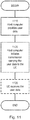
- a wireless device for switching between an active bandwidth part and a target bandwidth part as depicted by Figure 7 is provided.
- Each of the respective bandwidth parts comprise one or more resource blocks for use by the wireless device, the wireless device configured to receive a resource allocation field in a downlink control information in the active bandwidth part, the resource allocation field comprising information bits for allocating the one or more resource blocks in the target bandwidth part and interpret the resource allocation information bits based on a target bandwidth part resource allocation type wherein the target bandwidth resource allocation type indicates whether the information bits comprise a bitmap corresponding to one or more resource block groups or an integer value corresponding to a starting position and a length of the allocation and switch to the target bandwidth part to for a transmission or reception on the allocated resource blocks.
- Network node 600 may be composed of multiple physically separate components (e.g., a NodeB component and a RNC component, or a BTS component and a BSC component, etc.), which may each have their own respective components.
- network node 600 comprises multiple separate components (e.g., BTS and BSC components)
- one or more of the separate components may be shared among several network nodes.
- a single RNC may control multiple NodeB's.
- each unique NodeB and RNC pair may in some instances be considered a single separate network node.
- network node 600 may be configured to support multiple radio access technologies (RATs).
- RATs radio access technologies
- Network node 600 may also include multiple sets of the various illustrated components for different wireless technologies integrated into network node 600, such as, for example, GSM, WCDMA, LTE, NR, WiFi, or Bluetooth wireless technologies. These wireless technologies may be integrated into the same or different chip or set of chips and other components within a network node.
- Processing circuitry 630 is configured to perform any determining, calculating, or similar operations (e.g., certain obtaining operations) described herein as being provided by a network node. These operations performed by processing circuitry 630 may include processing information obtained by processing circuitry 630 by, for example, converting the obtained information into other information, comparing the obtained information or converted information to information stored in the network node, and/or performing one or more operations based on the obtained information or converted information, and as a result of said processing making a determination.
- processing information obtained by processing circuitry 630 by, for example, converting the obtained information into other information, comparing the obtained information or converted information to information stored in the network node, and/or performing one or more operations based on the obtained information or converted information, and as a result of said processing making a determination.
- Processing circuitry 630 may comprise a combination of one or more of a microprocessor, controller, microcontroller, central processing unit, digital signal processor, application-specific integrated circuit, field programmable gate array, or any other suitable computing device, resource, or combination of hardware, software and/or encoded logic operable to provide, either alone or in conjunction with other network node 600 components, such as device readable medium, network node 600 functionality.
- processing circuitry 630 may execute instructions stored in device readable medium or in memory 620 within processing circuitry 630. Such functionality may include providing any of the various wireless features, functions, or benefits discussed herein.
- processing circuitry 630 may include a system on a chip (SOC).
- SOC system on a chip
- processing circuitry 630 may include one or more of radio frequency (RF) transceiver circuitry 640 and baseband processing circuitry.
- radio frequency (RF) transceiver circuitry 640 and baseband processing circuitry may be on separate chips (or sets of chips), boards, or units, such as radio units and digital units.
- part or all of RF transceiver circuitry 640 and baseband processing circuitry may be on the same chip or set of chips, boards, or units
- processing circuitry 630 executing instructions stored on device readable medium 620 or memory within processing circuitry 630.
- some or all of the functionality may be provided by processing circuitry 630 without executing instructions stored on a separate or discrete device readable medium, such as in a hard-wired manner.
- processing circuitry 630 can be configured to perform the described functionality. The benefits provided by such functionality are not limited to processing circuitry 630 alone or to other components of network node 600, but are enjoyed by network node 600 as a whole, and/or by end users and the wireless network generally.
- Device readable medium 620 may comprise any form of volatile or non-volatile computer readable memory including, without limitation, persistent storage, solid-state memory, remotely mounted memory, magnetic media, optical media, random access memory (RAM), read-only memory (ROM), mass storage media (for example, a hard disk), removable storage media (for example, a flash drive, a Compact Disk (CD) or a Digital Video Disk (DVD)), and/or any other volatile or non-volatile, non-transitory device readable and/or computer-executable memory devices that store information, data, and/or instructions that may be used by processing circuitry 630.
- volatile or non-volatile computer readable memory including, without limitation, persistent storage, solid-state memory, remotely mounted memory, magnetic media, optical media, random access memory (RAM), read-only memory (ROM), mass storage media (for example, a hard disk), removable storage media (for example, a flash drive, a Compact Disk (CD) or a Digital Video Disk (DVD)), and/or any other volatile or
- Device readable medium 620 may store any suitable instructions, data or information, including a computer program, software, an application including one or more of logic, rules, code, tables, etc. and/or other instructions capable of being executed by processing circuitry 630 and, utilized by network node 600.
- Device readable medium 620 may be used to store any calculations made by processing circuitry 630 and/or any data received via an interface.
- processing circuitry 630 and device readable medium 620 may be considered to be integrated.
- the functions can be implemented by one or more applications (which can alternatively be called software instances, virtual appliances, network functions, virtual nodes, virtual network functions, etc.) operative to implement some of the features, functions, and/or benefits of some of the embodiments disclosed herein.
- Applications are run in virtualization environment which provides hardware comprising processing circuitry and memory.
- Memory contains instructions executable by processing circuitry whereby application is operative to provide one or more of the features, benefits, and/or functions disclosed herein.
- Virtualization environment comprises general-purpose or special-purpose network hardware devices comprising a set of one or more processors or processing circuitry, which can be commercial off-the-shelf (COTS) processors, dedicated Application Specific Integrated Circuits (ASICs), or any other type of processing circuitry including digital or analog hardware components or special purpose processors.
- Each hardware device can comprise memory which can be non-persistent memory for temporarily storing instructions or software executed by processing circuitry.
- Each hardware device can comprise one or more network interface controllers (NICs), also known as network interface cards, which include physical network interface.
- NICs network interface controllers
- Each hardware device can also include non-transitory, persistent, machine-readable storage media having stored therein software and/or instructions executable by processing circuitry.
- Software can include any type of software including software for instantiating one or more virtualization layers (also referred to as hypervisors), software to execute virtual machines as well as software allowing it to execute functions, features and/or benefits described in relation with some embodiments described herein.
- Virtual machines comprise virtual processing, virtual memory, virtual networking or interface and virtual storage, and can be run by a corresponding virtualization layer or hypervisor. Different embodiments of the instance of virtual appliance can be implemented on one or more of virtual machines, and the implementations can be made in different ways.
- processing circuitry executes software to instantiate the hypervisor or virtualization layer, which can sometimes be referred to as a virtual machine monitor (VMM).
- VMM virtual machine monitor
- Virtualization layer can present a virtual operating platform that appears like networking hardware to virtual machine.
- Hardware can be a standalone network node with generic or specific components. Hardware can comprise antenna and can implement some functions via virtualization. Alternatively, hardware can be part of a larger cluster of hardware (e.g. such as in a data center or customer premise equipment (CPE)) where many hardware nodes work together and are managed via management and orchestration (MANO), which, among others, oversees lifecycle management of applications.
- CPE customer premise equipment
- MANO management and orchestration
- NFV network function virtualization
- NFV can be used to consolidate many network equipment types onto industry standard high volume server hardware, physical switches, and physical storage, which can be located in data centers, and customer premise equipment.
- virtual machine can be a software implementation of a physical machine that runs programs as if they were executing on a physical, non-virtualized machine.
- Each of virtual machines, and that part of hardware that executes that virtual machine be it hardware dedicated to that virtual machine and/or hardware shared by that virtual machine with others of the virtual machines, forms a separate virtual network elements (VNE).
- VNE virtual network elements
- VNF Virtual Network Function
- one or more radio units that each include one or more transmitters and one or more receivers can be coupled to one or more antennas.
- Radio units can communicate directly with hardware nodes via one or more appropriate network interfaces and can be used in combination with the virtual components to provide a virtual node with radio capabilities, such as a radio access node or a base station.
- some signalling can be effected with the use of control system which can alternatively be used for communication between the hardware nodes and radio units.
- a communication system includes telecommunication network 810, such as a 3GPP-type cellular network, which comprises access network 811, such as a radio access network, and core network 814.
- Access network 811 comprises a plurality of base stations 812a, 812b, 812c, such as NBs, eNBs, gNBs or other types of wireless access points, each defining a corresponding coverage area 813a, 813b, 813c.
- Each base station 812a, 812b, 812c is connectable to core network 814 over a wired or wireless connection 815.
- a first UE 891 located in coverage area 813c can be configured to wirelessly connect to, or be paged by, the corresponding base station 812c.
- a second UE 892 in coverage area 813a is wirelessly connectable to the corresponding base station 812a. While a plurality of UEs 891, 892 are illustrated in this example, the disclosed embodiments are equally applicable to a situation where a sole UE is in the coverage area or where a sole UE is connecting to the corresponding base station 812.
- Telecommunication network 810 is itself connected to host computer 830, which can be embodied in the hardware and/or software of a standalone server, a cloud-implemented server, a distributed server or as processing resources in a server farm.
- Host computer 830 can be under the ownership or control of a service provider, or can be operated by the service provider or on behalf of the service provider.
- Connections 821 and 822 between telecommunication network 810 and host computer 830 can extend directly from core network 814 to host computer 830 or can go via an optional intermediate network 820.
- Intermediate network 820 can be one of, or a combination of more than one of, a public, private or hosted network; intermediate network 820, if any, can be a backbone network or the Internet; in particular, intermediate network 820 can comprise two or more sub-networks (not shown).
- the communication system of Figure 8 as a whole enables connectivity between the connected UEs 891, 892 and host computer 830.
- the connectivity can be described as an over-the-top (OTT) connection 850.
- Host computer 830 and the connected UEs 891, 892 are configured to communicate data and/or signaling via OTT connection 850, using access network 811, core network 814, any intermediate network 820 and possible further infrastructure (not shown) as intermediaries.
- OTT connection 850 can be transparent in the sense that the participating communication devices through which OTT connection 850 passes are unaware of routing of uplink and downlink communications.
- base station 812 may not or need not be informed about the past routing of an incoming downlink communication with data originating from host computer 830 to be forwarded (e.g., handed over) to a connected UE 891. Similarly, base station 812 need not be aware of the future routing of an outgoing uplink communication originating from the UE 891 towards the host computer 830.
- host computer 910 comprises hardware 915 including communication interface 916 configured to set up and maintain a wired or wireless connection with an interface of a different communication device of communication system 900.
- Host computer 910 further comprises processing circuitry 918, which can have storage and/or processing capabilities.
- processing circuitry 918 can comprise one or more programmable processors, application-specific integrated circuits, field programmable gate arrays or combinations of these (not shown) adapted to execute instructions.
- Host computer 910 further comprises software 911, which is stored in or accessible by host computer 910 and executable by processing circuitry 918.
- Software 911 includes host application 912.
- Host application 912 can be operable to provide a service to a remote user, such as UE 930 connecting via OTT connection 950 terminating at UE 930 and host computer 910. In providing the service to the remote user, host application 912 can provide user data which is transmitted using OTT connection 950.
- Communication system 900 can also include base station 920 provided in a telecommunication system and comprising hardware 925 enabling it to communicate with host computer 910 and with UE 930.
- Hardware 925 can include communication interface 926 for setting up and maintaining a wired or wireless connection with an interface of a different communication device of communication system 900, as well as radio interface 927 for setting up and maintaining at least wireless connection 970 with UE 930 located in a coverage area (not shown in Figure 9 ) served by base station 920.
- Communication interface 926 can be configured to facilitate connection 960 to host computer 910. Connection 960 can be direct or it can pass through a core network (not shown in Figure 9 ) of the telecommunication system and/or through one or more intermediate networks outside the telecommunication system.
- hardware 925 of base station 920 can also include processing circuitry 928, which can comprise one or more programmable processors, application-specific integrated circuits, field programmable gate arrays or combinations of these (not shown) adapted to execute instructions.
- processing circuitry 928 can comprise one or more programmable processors, application-specific integrated circuits, field programmable gate arrays or combinations of these (not shown) adapted to execute instructions.
- Base station 920 further has software 921 stored internally or accessible via an external connection.
- Communication system 900 can also include UE 930 already referred to. Its hardware 935 can include radio interface 937 configured to set up and maintain wireless connection 970 with a base station serving a coverage area in which UE 930 is currently located. Hardware 935 of UE 930 can also include processing circuitry 938, which can comprise one or more programmable processors, application-specific integrated circuits, field programmable gate arrays or combinations of these (not shown) adapted to execute instructions. UE 930 further comprises software 931, which is stored in or accessible by UE 930 and executable by processing circuitry 938. Software 931 includes client application 932. Client application 932 can be operable to provide a service to a human or non-human user via UE 930, with the support of host computer 910.
- an executing host application 912 can communicate with the executing client application 932 via OTT connection 950 terminating at UE 930 and host computer 910.
- client application 932 can receive request data from host application 912 and provide user data in response to the request data.
- OTT connection 950 can transfer both the request data and the user data.
- Client application 932 can interact with the user to generate the user data that it provides.
- host computer 910, base station 920 and UE 930 illustrated in Figure 9 can be similar or identical to host computer 830, one of base stations 812a, 812b, 812c and one of UEs 891, 892 of Figure 8 , respectively.
- the inner workings of these entities can be as shown in Figure 9 and independently, the surrounding network topology can be that of Figure 8 .
- OTT connection 950 has been drawn abstractly to illustrate the communication between host computer 910 and UE 930 via base station 920, without explicit reference to any intermediary devices and the precise routing of messages via these devices.
- Network infrastructure can determine the routing, which it can be configured to hide from UE 930 or from the service provider operating host computer 910, or both. While OTT connection 950 is active, the network infrastructure can further take decisions by which it dynamically changes the routing (e.g., on the basis of load balancing consideration or reconfiguration of the network).
- Wireless connection 970 between UE 930 and base station 920 is in accordance with the teachings of the embodiments described throughout this disclosure.
- One or more of the various embodiments improve the performance of OTT services provided to UE 930 using OTT connection 950, in which wireless connection 970 forms the last segment.
- the exemplary embodiments disclosed herein can improve flexibility for the network to monitor end-to-end quality-of-service (QoS) of data flows, including their corresponding radio bearers, associated with data sessions between a user equipment (UE) and another entity, such as an OTT data application or service external to the 5G network.
- QoS quality-of-service
- Such embodiments can facilitate flexible and timely control of data session QoS, which can lead to improvements in capacity, throughput, and in particular latency, for example when data transmission requirements vary dynamically within an OTT service which are implemented using multiple bandwidth parts and thus require efficient bandwidth part switching.
- BWP switching provides support for the many OTT services that are envisioned by 5G/NR and important for the growth of OTT services.
- a measurement procedure can be provided for the purpose of monitoring data rate, latency and other network operational aspects on which the one or more embodiments improve.
- the measurement procedure and/or the network functionality for reconfiguring OTT connection 950 can be implemented in software 911 and hardware 915 of host computer 910 or in software 931 and hardware 935 of UE 930, or both.
- sensors (not shown) can be deployed in or in association with communication devices through which OTT connection 950 passes; the sensors can participate in the measurement procedure by supplying values of the monitored quantities exemplified above, or supplying values of other physical quantities from which software 911, 931 can compute or estimate the monitored quantities.
- the reconfiguring of OTT connection 950 can include message format, retransmission settings, preferred routing etc.; the reconfiguring need not affect base station 920, and it can be unknown or imperceptible to base station 920. Such procedures and functionalities can be known and practiced in the art.
- measurements can involve proprietary UE signaling facilitating host computer 910's measurements of throughput, propagation times, latency and the like. The measurements can be implemented in that software 911 and 931 causes messages to be transmitted, in particular empty or 'dummy' messages, using OTT connection 950 while it monitors propagation times, errors etc.
- FIG. 10 is a flowchart illustrating an exemplary method and/or procedure implemented in a communication system, in accordance with one embodiment.
- the communication system includes a host computer, a base station and a UE which, in some exemplary embodiments, can be those described with reference to Figures 8 and 9 .
- the host computer provides user data.
- substep 1011 (which can be optional) of step 1010, the host computer provides the user data by executing a host application.
- the host computer initiates a transmission carrying the user data to the UE.
- step 1030 the base station transmits to the UE the user data which was carried in the transmission that the host computer initiated, in accordance with the teachings of the embodiments described throughout this disclosure.
- step 1040 the UE executes a client application associated with the host application executed by the host computer.
- FIG 11 is a flowchart illustrating an exemplary method and/or procedure implemented in a communication system, in accordance with one embodiment.
- the communication system includes a host computer, a base station and a UE which can be those described with reference to Figures 8 and 9 .
- the host computer provides user data.
- the host computer provides the user data by executing a host application.
- the host computer initiates a transmission carrying the user data to the UE.
- the transmission can pass via the base station, in accordance with the teachings of the embodiments described throughout this disclosure.
- step 1130 (which can be optional), the UE receives the user data carried in the transmission.
- FIG. 12 is a flowchart illustrating an exemplary method and/or procedure implemented in a communication system, in accordance with one embodiment.
- the communication system includes a host computer, a base station and a UE which can be those described with reference to Figures 8 and 9 .
- the UE receives input data provided by the host computer.
- the UE provides user data.
- substep 1221 (which can be optional) of step 1220, the UE provides the user data by executing a client application.
- substep 1211 (which can be optional) of step 1210, the UE executes a client application which provides the user data in reaction to the received input data provided by the host computer.
- the executed client application can further consider user input received from the user.
- the UE initiates, in substep 1230 (which can be optional), transmission of the user data to the host computer.
- step 1240 of the method the host computer receives the user data transmitted from the UE, in accordance with the teachings of the embodiments described throughout this disclosure.
- FIG. 13 is a flowchart illustrating an exemplary method and/or procedure implemented in a communication system, in accordance with one embodiment.
- the communication system includes a host computer, a base station and a UE which can be those described with reference to Figures 8 and 9 .
- the base station receives user data from the UE.
- the base station initiates transmission of the received user data to the host computer.
- the host computer receives the user data carried in the transmission initiated by the base station.
Landscapes
- Engineering & Computer Science (AREA)
- Signal Processing (AREA)
- Computer Networks & Wireless Communication (AREA)
- Mobile Radio Communication Systems (AREA)
- Data Exchanges In Wide-Area Networks (AREA)
Priority Applications (2)
| Application Number | Priority Date | Filing Date | Title |
|---|---|---|---|
| EP22151859.0A EP4048010A1 (en) | 2018-04-06 | 2019-04-05 | Bandwidth part switching |
| PL19717448T PL3777392T3 (pl) | 2018-04-06 | 2019-04-05 | Przełączanie części szerokości pasma |
Applications Claiming Priority (2)
| Application Number | Priority Date | Filing Date | Title |
|---|---|---|---|
| US201862653566P | 2018-04-06 | 2018-04-06 | |
| PCT/EP2019/058642 WO2019193153A1 (en) | 2018-04-06 | 2019-04-05 | Bandwidth part switching |
Related Child Applications (2)
| Application Number | Title | Priority Date | Filing Date |
|---|---|---|---|
| EP22151859.0A Division EP4048010A1 (en) | 2018-04-06 | 2019-04-05 | Bandwidth part switching |
| EP21193205.8 Division-Into | 2018-04-06 | 2021-08-26 |
Publications (2)
| Publication Number | Publication Date |
|---|---|
| EP3777392A1 EP3777392A1 (en) | 2021-02-17 |
| EP3777392B1 true EP3777392B1 (en) | 2021-10-06 |
Family
ID=66175399
Family Applications (2)
| Application Number | Title | Priority Date | Filing Date |
|---|---|---|---|
| EP22151859.0A Pending EP4048010A1 (en) | 2018-04-06 | 2019-04-05 | Bandwidth part switching |
| EP19717448.5A Active EP3777392B1 (en) | 2018-04-06 | 2019-04-05 | Bandwidth part switching |
Family Applications Before (1)
| Application Number | Title | Priority Date | Filing Date |
|---|---|---|---|
| EP22151859.0A Pending EP4048010A1 (en) | 2018-04-06 | 2019-04-05 | Bandwidth part switching |
Country Status (13)
| Country | Link |
|---|---|
| US (3) | US11647491B2 (zh) |
| EP (2) | EP4048010A1 (zh) |
| JP (2) | JP7198832B2 (zh) |
| KR (1) | KR102533876B1 (zh) |
| CN (1) | CN112237041A (zh) |
| AR (1) | AR114756A1 (zh) |
| BR (1) | BR112020020381A2 (zh) |
| DK (1) | DK3777392T3 (zh) |
| ES (1) | ES2900579T3 (zh) |
| HU (1) | HUE056929T2 (zh) |
| PL (1) | PL3777392T3 (zh) |
| RU (1) | RU2759513C1 (zh) |
| WO (1) | WO2019193153A1 (zh) |
Families Citing this family (17)
| Publication number | Priority date | Publication date | Assignee | Title |
|---|---|---|---|---|
| PL3777392T3 (pl) * | 2018-04-06 | 2022-02-14 | Telefonaktiebolaget Lm Ericsson (Publ) | Przełączanie części szerokości pasma |
| US11252710B2 (en) * | 2018-04-12 | 2022-02-15 | Mediatek Singapore Pte. Ltd. | Frequency domain resource allocation for compact downlink control information in mobile communications |
| CN111565461A (zh) * | 2019-02-14 | 2020-08-21 | 夏普株式会社 | 由用户设备执行的方法以及用户设备 |
| CN116546154A (zh) * | 2019-10-11 | 2023-08-04 | RealMe重庆移动通信有限公司 | 网络视频通话方法、装置以及电子设备 |
| WO2021080314A1 (ko) * | 2019-10-21 | 2021-04-29 | 엘지전자 주식회사 | 무선 통신 시스템에서 신호를 송수신하는 방법 및 장치 |
| CN115942491A (zh) * | 2019-11-14 | 2023-04-07 | 维沃移动通信有限公司 | 一种上行资源确定方法、指示方法、终端和网络设备 |
| CN110913487B (zh) * | 2019-11-20 | 2022-11-01 | 京信网络系统股份有限公司 | 资源分配方法、装置、基站和存储介质 |
| US20230353319A1 (en) * | 2019-12-24 | 2023-11-02 | Qualcomm Incorporated | Bandwidth operation for full duplex user equipment |
| CN114846881A (zh) * | 2020-01-22 | 2022-08-02 | 华为技术有限公司 | 一种确定初始带宽部分bwp的方法、装置及存储介质 |
| US11523377B2 (en) * | 2020-02-14 | 2022-12-06 | T-Mobile Usa, Inc. | LTE resource allocation controller |
| CN113630873A (zh) | 2020-05-08 | 2021-11-09 | 维沃移动通信有限公司 | 频域资源分配方法及设备 |
| CN115606283A (zh) * | 2020-05-15 | 2023-01-13 | 苹果公司(Us) | 在未许可频谱中用于调度的pusch传输的资源分配的系统、方法和装置 |
| CN112332999B (zh) * | 2020-09-23 | 2023-08-01 | 深圳Tcl新技术有限公司 | 带宽分配方法、装置、设备及计算机可读存储介质 |
| WO2022077375A1 (zh) * | 2020-10-15 | 2022-04-21 | 华为技术有限公司 | 一种通信方法及装置 |
| US11621798B2 (en) * | 2021-02-02 | 2023-04-04 | Cisco Technology, Inc. | Signaling of preamble puncturing configuration in a non-high throughput RTS/CTS exchange |
| CN113329508B (zh) * | 2021-06-08 | 2022-05-24 | 杭州红岭通信息科技有限公司 | 一种下行物理共享信道pdsch资源分配方法 |
| US11895635B2 (en) | 2021-06-09 | 2024-02-06 | Charter Communications Operating, Llc | Methods and apparatus for managing spectrum allocation in wireless networks |
Family Cites Families (16)
| Publication number | Priority date | Publication date | Assignee | Title |
|---|---|---|---|---|
| RO114062B1 (ro) | 1992-11-06 | 1998-12-30 | At & T Corp American Telephone | Metoda de stabilire a apelurilor comutate de circuit intr-o retea si retea de telecomunicatii conform metodei |
| KR101586622B1 (ko) * | 2009-01-15 | 2016-02-02 | 삼성전자주식회사 | 이동통신 시스템에서 대역폭 결합을 위한 pdcch 전송 방법 및 시스템 |
| EP3490320B1 (en) * | 2011-09-30 | 2023-08-23 | InterDigital Patent Holdings, Inc. | Device communication using a reduced channel bandwidth |
| US9094845B2 (en) * | 2011-10-07 | 2015-07-28 | Telefonaktiebolaget L M Ericsson (Publ) | Methods and arrangements in a wireless communication system |
| EP2595425A1 (en) * | 2011-11-18 | 2013-05-22 | Panasonic Corporation | Active bandwidth indicator for power-saving UEs |
| EP2807784A1 (en) | 2012-01-27 | 2014-12-03 | Interdigital Patent Holdings, Inc. | Systems and/or methods for providing epdcch in a multiple carrier based and/or quasi-collated network |
| EP3185497B1 (en) * | 2014-08-21 | 2019-03-20 | LG Electronics Inc. | Method for uplink transmission in wireless communication system and apparatus therefor |
| KR102377440B1 (ko) | 2014-09-26 | 2022-03-23 | 선 페이턴트 트러스트 | 디바이스 투 디바이스(d2d) 통신에 대한 개선된 자원 할당 |
| KR102548620B1 (ko) | 2014-10-01 | 2023-06-29 | 엘지전자 주식회사 | 무선 통신 시스템에서 데이터 전송 방법 및 이를 위한 장치 |
| US20170171752A1 (en) * | 2015-12-14 | 2017-06-15 | Qualcomm Incorporated | Securing signaling interface between radio access network and a service management entity to support service slicing |
| RU2725164C2 (ru) | 2016-05-13 | 2020-06-30 | Телефонактиеболагет Лм Эрикссон (Пабл) | Способы и пользовательское оборудование, радиопередающее устройство и сетевой узел для управления опорными сигналами позиционирования |
| US10367677B2 (en) | 2016-05-13 | 2019-07-30 | Telefonaktiebolaget Lm Ericsson (Publ) | Network architecture, methods, and devices for a wireless communications network |
| EP3934357B1 (en) | 2016-08-11 | 2024-05-15 | Samsung Electronics Co., Ltd. | Method and apparatus of data transmission in next generation cellular networks |
| WO2018086913A1 (en) | 2016-11-14 | 2018-05-17 | Telefonaktiebolaget Lm Ericsson (Publ) | Methods of wireless device and network node, such wireless device and network node, and computer programs thereof |
| US11133912B2 (en) | 2017-10-02 | 2021-09-28 | Qualcomm Incorporated | Bandwidth part activation, deactivation, and switching in wireless communications |
| PL3777392T3 (pl) * | 2018-04-06 | 2022-02-14 | Telefonaktiebolaget Lm Ericsson (Publ) | Przełączanie części szerokości pasma |
-
2019
- 2019-04-05 PL PL19717448T patent/PL3777392T3/pl unknown
- 2019-04-05 WO PCT/EP2019/058642 patent/WO2019193153A1/en unknown
- 2019-04-05 RU RU2020135524A patent/RU2759513C1/ru active
- 2019-04-05 US US17/044,969 patent/US11647491B2/en active Active
- 2019-04-05 HU HUE19717448A patent/HUE056929T2/hu unknown
- 2019-04-05 KR KR1020207032142A patent/KR102533876B1/ko active IP Right Grant
- 2019-04-05 US US16/376,464 patent/US10602519B2/en active Active
- 2019-04-05 DK DK19717448.5T patent/DK3777392T3/da active
- 2019-04-05 CN CN201980037674.XA patent/CN112237041A/zh active Pending
- 2019-04-05 EP EP22151859.0A patent/EP4048010A1/en active Pending
- 2019-04-05 BR BR112020020381-5A patent/BR112020020381A2/pt unknown
- 2019-04-05 JP JP2020554498A patent/JP7198832B2/ja active Active
- 2019-04-05 ES ES19717448T patent/ES2900579T3/es active Active
- 2019-04-05 EP EP19717448.5A patent/EP3777392B1/en active Active
- 2019-04-08 AR ARP190100925A patent/AR114756A1/es active IP Right Grant
-
2022
- 2022-12-19 JP JP2022202277A patent/JP2023051981A/ja active Pending
-
2023
- 2023-03-20 US US18/186,509 patent/US20230224881A1/en active Pending
Also Published As
| Publication number | Publication date |
|---|---|
| KR102533876B1 (ko) | 2023-05-19 |
| BR112020020381A2 (pt) | 2021-01-12 |
| HUE056929T2 (hu) | 2022-03-28 |
| US11647491B2 (en) | 2023-05-09 |
| EP4048010A1 (en) | 2022-08-24 |
| RU2759513C1 (ru) | 2021-11-15 |
| ES2900579T3 (es) | 2022-03-17 |
| US10602519B2 (en) | 2020-03-24 |
| JP7198832B2 (ja) | 2023-01-04 |
| PL3777392T3 (pl) | 2022-02-14 |
| KR20200139803A (ko) | 2020-12-14 |
| CN112237041A (zh) | 2021-01-15 |
| US20230224881A1 (en) | 2023-07-13 |
| DK3777392T3 (da) | 2021-11-22 |
| JP2021520733A (ja) | 2021-08-19 |
| EP3777392A1 (en) | 2021-02-17 |
| AR114756A1 (es) | 2020-10-14 |
| JP2023051981A (ja) | 2023-04-11 |
| WO2019193153A1 (en) | 2019-10-10 |
| US20210258926A1 (en) | 2021-08-19 |
| US20190313412A1 (en) | 2019-10-10 |
Similar Documents
| Publication | Publication Date | Title |
|---|---|---|
| EP3777392B1 (en) | Bandwidth part switching | |
| US11895633B2 (en) | Signalling of frequency-domain resource assignment | |
| EP3606218B1 (en) | User equipment, base station, and related method | |
| US20230007524A1 (en) | Methods for Enabling a Low Bandwidth Wireless Device to Access a New Radio Cell via a Wideband Control Resource Set | |
| JP2022516935A (ja) | Nrユーザ機器のための選択的クロススロットスケジューリング | |
| JP7361880B2 (ja) | マルチユーザ送信における送信パラメータ値を選択するための方法および装置 | |
| US11902988B2 (en) | Handling misalignment between arrival of critical data for transmission and transmission occasions of a configured grant | |
| CN113711678A (zh) | 网络节点、用户设备(ue)和用于由网络节点调度ue的相关方法 | |
| US20230397194A1 (en) | Apparatuses and Methods for Scheduling Resources | |
| JP2023175870A (ja) | コンポーネントキャリア上の制御チャネルを取り扱うための技術 | |
| OA20333A (en) | Bandwidth part switching. | |
| US20240137943A1 (en) | Handling misalignment between arrival of critical data for transmission and transmission occasions of a configured grant | |
| WO2020029675A1 (en) | Method and apparatus for sounding reference signal transmission |
Legal Events
| Date | Code | Title | Description |
|---|---|---|---|
| STAA | Information on the status of an ep patent application or granted ep patent |
Free format text: STATUS: UNKNOWN |
|
| STAA | Information on the status of an ep patent application or granted ep patent |
Free format text: STATUS: THE INTERNATIONAL PUBLICATION HAS BEEN MADE |
|
| PUAI | Public reference made under article 153(3) epc to a published international application that has entered the european phase |
Free format text: ORIGINAL CODE: 0009012 |
|
| STAA | Information on the status of an ep patent application or granted ep patent |
Free format text: STATUS: REQUEST FOR EXAMINATION WAS MADE |
|
| 17P | Request for examination filed |
Effective date: 20201105 |
|
| AK | Designated contracting states |
Kind code of ref document: A1 Designated state(s): AL AT BE BG CH CY CZ DE DK EE ES FI FR GB GR HR HU IE IS IT LI LT LU LV MC MK MT NL NO PL PT RO RS SE SI SK SM TR |
|
| AX | Request for extension of the european patent |
Extension state: BA ME |
|
| GRAP | Despatch of communication of intention to grant a patent |
Free format text: ORIGINAL CODE: EPIDOSNIGR1 |
|
| STAA | Information on the status of an ep patent application or granted ep patent |
Free format text: STATUS: GRANT OF PATENT IS INTENDED |
|
| RIC1 | Information provided on ipc code assigned before grant |
Ipc: H04W 72/04 20090101AFI20210401BHEP Ipc: H04W 36/06 20090101ALI20210401BHEP Ipc: H04L 5/00 20060101ALI20210401BHEP |
|
| DAV | Request for validation of the european patent (deleted) | ||
| DAX | Request for extension of the european patent (deleted) | ||
| INTG | Intention to grant announced |
Effective date: 20210420 |
|
| GRAS | Grant fee paid |
Free format text: ORIGINAL CODE: EPIDOSNIGR3 |
|
| GRAA | (expected) grant |
Free format text: ORIGINAL CODE: 0009210 |
|
| STAA | Information on the status of an ep patent application or granted ep patent |
Free format text: STATUS: THE PATENT HAS BEEN GRANTED |
|
| AK | Designated contracting states |
Kind code of ref document: B1 Designated state(s): AL AT BE BG CH CY CZ DE DK EE ES FI FR GB GR HR HU IE IS IT LI LT LU LV MC MK MT NL NO PL PT RO RS SE SI SK SM TR |
|
| REG | Reference to a national code |
Ref country code: GB Ref legal event code: FG4D |
|
| REG | Reference to a national code |
Ref country code: CH Ref legal event code: EP Ref country code: AT Ref legal event code: REF Ref document number: 1437379 Country of ref document: AT Kind code of ref document: T Effective date: 20211015 |
|
| REG | Reference to a national code |
Ref country code: DE Ref legal event code: R096 Ref document number: 602019008198 Country of ref document: DE |
|
| REG | Reference to a national code |
Ref country code: IE Ref legal event code: FG4D |
|
| REG | Reference to a national code |
Ref country code: DK Ref legal event code: T3 Effective date: 20211118 |
|
| REG | Reference to a national code |
Ref country code: GR Ref legal event code: EP Ref document number: 20210403099 Country of ref document: GR Effective date: 20211209 |
|
| REG | Reference to a national code |
Ref country code: NL Ref legal event code: FP |
|
| REG | Reference to a national code |
Ref country code: LT Ref legal event code: MG9D |
|
| REG | Reference to a national code |
Ref country code: ES Ref legal event code: FG2A Ref document number: 2900579 Country of ref document: ES Kind code of ref document: T3 Effective date: 20220317 |
|
| REG | Reference to a national code |
Ref country code: HU Ref legal event code: AG4A Ref document number: E056929 Country of ref document: HU |
|
| PG25 | Lapsed in a contracting state [announced via postgrant information from national office to epo] |
Ref country code: RS Free format text: LAPSE BECAUSE OF FAILURE TO SUBMIT A TRANSLATION OF THE DESCRIPTION OR TO PAY THE FEE WITHIN THE PRESCRIBED TIME-LIMIT Effective date: 20211006 Ref country code: LT Free format text: LAPSE BECAUSE OF FAILURE TO SUBMIT A TRANSLATION OF THE DESCRIPTION OR TO PAY THE FEE WITHIN THE PRESCRIBED TIME-LIMIT Effective date: 20211006 Ref country code: FI Free format text: LAPSE BECAUSE OF FAILURE TO SUBMIT A TRANSLATION OF THE DESCRIPTION OR TO PAY THE FEE WITHIN THE PRESCRIBED TIME-LIMIT Effective date: 20211006 Ref country code: BG Free format text: LAPSE BECAUSE OF FAILURE TO SUBMIT A TRANSLATION OF THE DESCRIPTION OR TO PAY THE FEE WITHIN THE PRESCRIBED TIME-LIMIT Effective date: 20220106 |
|
| PG25 | Lapsed in a contracting state [announced via postgrant information from national office to epo] |
Ref country code: IS Free format text: LAPSE BECAUSE OF FAILURE TO SUBMIT A TRANSLATION OF THE DESCRIPTION OR TO PAY THE FEE WITHIN THE PRESCRIBED TIME-LIMIT Effective date: 20220206 Ref country code: SE Free format text: LAPSE BECAUSE OF FAILURE TO SUBMIT A TRANSLATION OF THE DESCRIPTION OR TO PAY THE FEE WITHIN THE PRESCRIBED TIME-LIMIT Effective date: 20211006 Ref country code: PT Free format text: LAPSE BECAUSE OF FAILURE TO SUBMIT A TRANSLATION OF THE DESCRIPTION OR TO PAY THE FEE WITHIN THE PRESCRIBED TIME-LIMIT Effective date: 20220207 Ref country code: NO Free format text: LAPSE BECAUSE OF FAILURE TO SUBMIT A TRANSLATION OF THE DESCRIPTION OR TO PAY THE FEE WITHIN THE PRESCRIBED TIME-LIMIT Effective date: 20220106 Ref country code: LV Free format text: LAPSE BECAUSE OF FAILURE TO SUBMIT A TRANSLATION OF THE DESCRIPTION OR TO PAY THE FEE WITHIN THE PRESCRIBED TIME-LIMIT Effective date: 20211006 Ref country code: HR Free format text: LAPSE BECAUSE OF FAILURE TO SUBMIT A TRANSLATION OF THE DESCRIPTION OR TO PAY THE FEE WITHIN THE PRESCRIBED TIME-LIMIT Effective date: 20211006 |
|
| REG | Reference to a national code |
Ref country code: DE Ref legal event code: R097 Ref document number: 602019008198 Country of ref document: DE |
|
| PG25 | Lapsed in a contracting state [announced via postgrant information from national office to epo] |
Ref country code: SM Free format text: LAPSE BECAUSE OF FAILURE TO SUBMIT A TRANSLATION OF THE DESCRIPTION OR TO PAY THE FEE WITHIN THE PRESCRIBED TIME-LIMIT Effective date: 20211006 Ref country code: SK Free format text: LAPSE BECAUSE OF FAILURE TO SUBMIT A TRANSLATION OF THE DESCRIPTION OR TO PAY THE FEE WITHIN THE PRESCRIBED TIME-LIMIT Effective date: 20211006 Ref country code: RO Free format text: LAPSE BECAUSE OF FAILURE TO SUBMIT A TRANSLATION OF THE DESCRIPTION OR TO PAY THE FEE WITHIN THE PRESCRIBED TIME-LIMIT Effective date: 20211006 Ref country code: EE Free format text: LAPSE BECAUSE OF FAILURE TO SUBMIT A TRANSLATION OF THE DESCRIPTION OR TO PAY THE FEE WITHIN THE PRESCRIBED TIME-LIMIT Effective date: 20211006 |
|
| PLBE | No opposition filed within time limit |
Free format text: ORIGINAL CODE: 0009261 |
|
| STAA | Information on the status of an ep patent application or granted ep patent |
Free format text: STATUS: NO OPPOSITION FILED WITHIN TIME LIMIT |
|
| 26N | No opposition filed |
Effective date: 20220707 |
|
| REG | Reference to a national code |
Ref country code: AT Ref legal event code: UEP Ref document number: 1437379 Country of ref document: AT Kind code of ref document: T Effective date: 20211006 |
|
| PG25 | Lapsed in a contracting state [announced via postgrant information from national office to epo] |
Ref country code: AL Free format text: LAPSE BECAUSE OF FAILURE TO SUBMIT A TRANSLATION OF THE DESCRIPTION OR TO PAY THE FEE WITHIN THE PRESCRIBED TIME-LIMIT Effective date: 20211006 |
|
| REG | Reference to a national code |
Ref country code: BE Ref legal event code: MM Effective date: 20220430 |
|
| PG25 | Lapsed in a contracting state [announced via postgrant information from national office to epo] |
Ref country code: MC Free format text: LAPSE BECAUSE OF FAILURE TO SUBMIT A TRANSLATION OF THE DESCRIPTION OR TO PAY THE FEE WITHIN THE PRESCRIBED TIME-LIMIT Effective date: 20211006 Ref country code: LU Free format text: LAPSE BECAUSE OF NON-PAYMENT OF DUE FEES Effective date: 20220405 |
|
| PG25 | Lapsed in a contracting state [announced via postgrant information from national office to epo] |
Ref country code: BE Free format text: LAPSE BECAUSE OF NON-PAYMENT OF DUE FEES Effective date: 20220430 |
|
| PGFP | Annual fee paid to national office [announced via postgrant information from national office to epo] |
Ref country code: TR Payment date: 20230322 Year of fee payment: 5 Ref country code: PL Payment date: 20230321 Year of fee payment: 5 |
|
| P01 | Opt-out of the competence of the unified patent court (upc) registered |
Effective date: 20230523 |
|
| PGFP | Annual fee paid to national office [announced via postgrant information from national office to epo] |
Ref country code: IT Payment date: 20230419 Year of fee payment: 5 Ref country code: IE Payment date: 20230427 Year of fee payment: 5 Ref country code: FR Payment date: 20230425 Year of fee payment: 5 Ref country code: ES Payment date: 20230503 Year of fee payment: 5 Ref country code: DK Payment date: 20230427 Year of fee payment: 5 Ref country code: DE Payment date: 20230427 Year of fee payment: 5 Ref country code: CH Payment date: 20230502 Year of fee payment: 5 |
|
| PGFP | Annual fee paid to national office [announced via postgrant information from national office to epo] |
Ref country code: HU Payment date: 20230331 Year of fee payment: 5 Ref country code: GR Payment date: 20230428 Year of fee payment: 5 |
|
| PGFP | Annual fee paid to national office [announced via postgrant information from national office to epo] |
Ref country code: GB Payment date: 20230427 Year of fee payment: 5 |
|
| PG25 | Lapsed in a contracting state [announced via postgrant information from national office to epo] |
Ref country code: MK Free format text: LAPSE BECAUSE OF FAILURE TO SUBMIT A TRANSLATION OF THE DESCRIPTION OR TO PAY THE FEE WITHIN THE PRESCRIBED TIME-LIMIT Effective date: 20211006 Ref country code: CY Free format text: LAPSE BECAUSE OF FAILURE TO SUBMIT A TRANSLATION OF THE DESCRIPTION OR TO PAY THE FEE WITHIN THE PRESCRIBED TIME-LIMIT Effective date: 20211006 |
|
| PGFP | Annual fee paid to national office [announced via postgrant information from national office to epo] |
Ref country code: CZ Payment date: 20240321 Year of fee payment: 6 |
|
| PGFP | Annual fee paid to national office [announced via postgrant information from national office to epo] |
Ref country code: NL Payment date: 20240426 Year of fee payment: 6 |