EP3776449B1 - Verfahren zum fahrzeugbildvergleich und system dafür - Google Patents
Verfahren zum fahrzeugbildvergleich und system dafür Download PDFInfo
- Publication number
- EP3776449B1 EP3776449B1 EP19776128.1A EP19776128A EP3776449B1 EP 3776449 B1 EP3776449 B1 EP 3776449B1 EP 19776128 A EP19776128 A EP 19776128A EP 3776449 B1 EP3776449 B1 EP 3776449B1
- Authority
- EP
- European Patent Office
- Prior art keywords
- image
- segment
- input
- difference map
- vehicle
- Prior art date
- Legal status (The legal status is an assumption and is not a legal conclusion. Google has not performed a legal analysis and makes no representation as to the accuracy of the status listed.)
- Active
Links
Images



Classifications
-
- G—PHYSICS
- G06—COMPUTING OR CALCULATING; COUNTING
- G06T—IMAGE DATA PROCESSING OR GENERATION, IN GENERAL
- G06T7/00—Image analysis
- G06T7/0002—Inspection of images, e.g. flaw detection
- G06T7/0004—Industrial image inspection
- G06T7/001—Industrial image inspection using an image reference approach
-
- G—PHYSICS
- G06—COMPUTING OR CALCULATING; COUNTING
- G06F—ELECTRIC DIGITAL DATA PROCESSING
- G06F18/00—Pattern recognition
- G06F18/20—Analysing
- G06F18/22—Matching criteria, e.g. proximity measures
-
- G—PHYSICS
- G06—COMPUTING OR CALCULATING; COUNTING
- G06T—IMAGE DATA PROCESSING OR GENERATION, IN GENERAL
- G06T7/00—Image analysis
- G06T7/10—Segmentation; Edge detection
- G06T7/11—Region-based segmentation
-
- G—PHYSICS
- G06—COMPUTING OR CALCULATING; COUNTING
- G06T—IMAGE DATA PROCESSING OR GENERATION, IN GENERAL
- G06T7/00—Image analysis
- G06T7/10—Segmentation; Edge detection
- G06T7/143—Segmentation; Edge detection involving probabilistic approaches, e.g. Markov random field [MRF] modelling
-
- G—PHYSICS
- G06—COMPUTING OR CALCULATING; COUNTING
- G06T—IMAGE DATA PROCESSING OR GENERATION, IN GENERAL
- G06T7/00—Image analysis
- G06T7/10—Segmentation; Edge detection
- G06T7/174—Segmentation; Edge detection involving the use of two or more images
-
- G—PHYSICS
- G06—COMPUTING OR CALCULATING; COUNTING
- G06V—IMAGE OR VIDEO RECOGNITION OR UNDERSTANDING
- G06V10/00—Arrangements for image or video recognition or understanding
- G06V10/20—Image preprocessing
- G06V10/25—Determination of region of interest [ROI] or a volume of interest [VOI]
-
- G—PHYSICS
- G06—COMPUTING OR CALCULATING; COUNTING
- G06V—IMAGE OR VIDEO RECOGNITION OR UNDERSTANDING
- G06V10/00—Arrangements for image or video recognition or understanding
- G06V10/40—Extraction of image or video features
- G06V10/44—Local feature extraction by analysis of parts of the pattern, e.g. by detecting edges, contours, loops, corners, strokes or intersections; Connectivity analysis, e.g. of connected components
- G06V10/443—Local feature extraction by analysis of parts of the pattern, e.g. by detecting edges, contours, loops, corners, strokes or intersections; Connectivity analysis, e.g. of connected components by matching or filtering
- G06V10/449—Biologically inspired filters, e.g. difference of Gaussians [DoG] or Gabor filters
- G06V10/451—Biologically inspired filters, e.g. difference of Gaussians [DoG] or Gabor filters with interaction between the filter responses, e.g. cortical complex cells
- G06V10/454—Integrating the filters into a hierarchical structure, e.g. convolutional neural networks [CNN]
-
- G—PHYSICS
- G06—COMPUTING OR CALCULATING; COUNTING
- G06V—IMAGE OR VIDEO RECOGNITION OR UNDERSTANDING
- G06V10/00—Arrangements for image or video recognition or understanding
- G06V10/70—Arrangements for image or video recognition or understanding using pattern recognition or machine learning
- G06V10/74—Image or video pattern matching; Proximity measures in feature spaces
- G06V10/761—Proximity, similarity or dissimilarity measures
-
- G—PHYSICS
- G06—COMPUTING OR CALCULATING; COUNTING
- G06V—IMAGE OR VIDEO RECOGNITION OR UNDERSTANDING
- G06V10/00—Arrangements for image or video recognition or understanding
- G06V10/70—Arrangements for image or video recognition or understanding using pattern recognition or machine learning
- G06V10/82—Arrangements for image or video recognition or understanding using pattern recognition or machine learning using neural networks
-
- G—PHYSICS
- G06—COMPUTING OR CALCULATING; COUNTING
- G06T—IMAGE DATA PROCESSING OR GENERATION, IN GENERAL
- G06T2207/00—Indexing scheme for image analysis or image enhancement
- G06T2207/20—Special algorithmic details
- G06T2207/20081—Training; Learning
-
- G—PHYSICS
- G06—COMPUTING OR CALCULATING; COUNTING
- G06T—IMAGE DATA PROCESSING OR GENERATION, IN GENERAL
- G06T2207/00—Indexing scheme for image analysis or image enhancement
- G06T2207/20—Special algorithmic details
- G06T2207/20084—Artificial neural networks [ANN]
-
- G—PHYSICS
- G06—COMPUTING OR CALCULATING; COUNTING
- G06T—IMAGE DATA PROCESSING OR GENERATION, IN GENERAL
- G06T2207/00—Indexing scheme for image analysis or image enhancement
- G06T2207/30—Subject of image; Context of image processing
- G06T2207/30108—Industrial image inspection
- G06T2207/30164—Workpiece; Machine component
-
- G—PHYSICS
- G06—COMPUTING OR CALCULATING; COUNTING
- G06T—IMAGE DATA PROCESSING OR GENERATION, IN GENERAL
- G06T2207/00—Indexing scheme for image analysis or image enhancement
- G06T2207/30—Subject of image; Context of image processing
- G06T2207/30248—Vehicle exterior or interior
-
- G—PHYSICS
- G06—COMPUTING OR CALCULATING; COUNTING
- G06T—IMAGE DATA PROCESSING OR GENERATION, IN GENERAL
- G06T2207/00—Indexing scheme for image analysis or image enhancement
- G06T2207/30—Subject of image; Context of image processing
- G06T2207/30248—Vehicle exterior or interior
- G06T2207/30252—Vehicle exterior; Vicinity of vehicle
-
- G—PHYSICS
- G06—COMPUTING OR CALCULATING; COUNTING
- G06V—IMAGE OR VIDEO RECOGNITION OR UNDERSTANDING
- G06V2201/00—Indexing scheme relating to image or video recognition or understanding
- G06V2201/08—Detecting or categorising vehicles
Definitions
- the presently disclosed subject matter relates, in general, to the field of vehicle image analysis, and more specifically, to methods and systems for vehicle image comparison.
- Inspection of a motor vehicle is commonly performed manually by a technician. Images of a vehicle are sometimes captured for the purpose of assisting the manual inspection process and providing visual evidence of the inspection. This process is usually cumbersome and time-consuming.
- US 2016/178790 Al discloses a vehicle inspection method and system comprising: implementing a ray scanning inspection on an inspected vehicle to obtain a ray scanning inspection image of the inspected vehicle, extracting vehicle characteristic information, comparing the vehicle characteristic information of the inspected vehicle to vehicle reference characteristics stored in a storage unit, selecting a vehicle reference characteristic which is closest to the vehicle characteristic information, and finding out a closest ray transmission reference image on the basis of a corresponding relationship between the vehicle reference characteristics and ray transmission reference images stored in the storage unit, determining a first distinguishing area of the ray scanning inspection image from the closest ray transmission reference image by comparing the ray scanning inspection image of the inspected vehicle to the closest ray transmission reference image.
- US 2017/293894 Al discloses a method for automatically estimating a repair cost for a vehicle, comprising: receiving one or more images of a damaged vehicle from a client computing device, performing computerized image processing on each of the one or more images to detect damage to a set of parts of the vehicle, and calculating an estimated repair cost for the vehicle based on the detected damage based on accessing a parts database that includes repair costs.
- US 9 886 771 B1 discloses an image processing system that obtains source images in which a damaged vehicle is represented, and performs image processing techniques to determine, predict, estimate, and/or detect damage that has occurred at various locations on the vehicle.
- the image processing techniques may include generating a composite image of the damaged vehicle, aligning and/or isolating the image, applying convolutional neural network techniques to the image to generate damage parameter values, where each value corresponds to damage in a particular location of vehicle, and/or other techniques.
- a computerized method of vehicle image comparison comprising: obtaining an input image acquired by an imaging device capturing at least part of a vehicle; segmenting the input image into one or more input segments corresponding to one or more mechanical components comprised in the at least part of the vehicle using a segmentation model; retrieving a set of reference images, wherein each reference image within the set comprises at least one reference segment corresponding to at least one input segment of the one or more input segments, thereby obtaining a respective set of corresponding reference segments for each input segment of the at least one input segment; and generating at least one difference map corresponding to the at least one input segment comprising, for each given input segment: comparing the given input segment with each corresponding reference segment within the respective set of reference segments thereof using a comparison model, giving rise to a set of difference map candidates each indicating probability of presence of difference of interest (DOI) between the given input segment and the corresponding reference segment, the DOI representative of physical change of the vehicle; and providing a difference map
- DOI difference of interest
- the method according to this aspect of the presently disclosed subject matter can comprise one or more of features (i) to (xiii) listed below, in any desired combination or permutation which is technically possible:
- a computerized system of vehicle image comparison comprising a processor and memory circuitry (PMC) operatively connected to an I/O interface, wherein: the I/O interface is configured to obtain an input image acquired by an imaging device capturing at least part of a vehicle; and the PMC is configured to: segment the input image into one or more input segments corresponding to one or more mechanical components comprised in the at least part of the vehicle using a segmentation model; retrieve a set of reference images, wherein each reference image within the set comprises at least one reference segment corresponding to at least one input segment of the one or more input segments, thereby obtaining a respective set of corresponding reference segments for each input segment of the at least one input segment; and generate at least one difference map corresponding to the at least one input segment, comprising, for each given input segment: comparing the given input segment with each corresponding reference segment within the respective set of reference segments thereof using a comparison model, giving rise to a set of difference map candidates each indicating probability
- This aspect of the disclosed subject matter can comprise one or more of features (i) to (xiii) listed above with respect to the method, mutatis mutandis, in any desired combination or permutation which is technically possible.
- a non-transitory computer readable storage medium tangibly embodying a program of instructions that, when executed by a computer, cause the computer to perform a method of vehicle image comparison, the method comprising: obtaining an input image acquired by an imaging device capturing at least part of a vehicle; segmenting the input image into one or more input segments corresponding to one or more mechanical components comprised in the at least part of the vehicle using a segmentation model; retrieving a set of reference images, wherein each reference image within the set comprises at least one reference segment corresponding to at least one input segment of the one or more input segments, thereby obtaining a respective set of corresponding reference segments for each input segment of the at least one input segment; and generating at least one difference map corresponding to the at least one input segment, comprising, for each given input segment: comparing the given input segment with each corresponding reference segment within the respective set of reference segments thereof using a comparison model, giving rise to a set of difference map candidates each indicating probability of presence
- This aspect of the disclosed subject matter can comprise one or more of features (i) to (xiii) listed above with respect to the method, mutatis mutandis, in any desired combination or permutation which is technically possible.
- non-transitory memory non-transitory storage medium
- non-transitory computer readable storage medium used herein should be expansively construed to cover any volatile or non-volatile computer memory suitable to the presently disclosed subject matter.
- Embodiments of the presently disclosed subject matter are not described with reference to any particular programming language. It will be appreciated that a variety of programming languages may be used to implement the teachings of the presently disclosed subject matter as described herein.
- the phrase “for example,” “such as”, “for instance” and variants thereof describe non-limiting embodiments of the presently disclosed subject matter.
- Reference in the specification to “one case”, “some cases”, “other cases” or variants thereof means that a particular feature, structure or characteristic described in connection with the embodiment(s) is included in at least one embodiment of the presently disclosed subject matter.
- the appearance of the phrase “one case”, “some cases”, “other cases” or variants thereof does not necessarily refer to the same embodiment(s).
- one or more stages illustrated in the figures may be executed in a different order and/or one or more groups of stages may be executed simultaneously and vice versa.
- FIG. 1 schematically illustrating a block diagram of a computerized system capable of comparing vehicle images in accordance with certain embodiments of the presently disclosed subject matter.
- the system 100 illustrated in Fig. 1 is a computer-based vehicle image comparison system.
- System 100 can be configured to obtain, via a hardware-based I/O interface 120, an input image (also termed as target image) acquired by an imaging device 120.
- the input image captures at least part of a vehicle.
- vehicle used herein should be expansively construed to cover any kind of motor vehicle, including but not limited to cars, buses, motorcycles, trucks, trains, and airplanes, etc.
- the present disclosure is not limited by the type and usage of a specific vehicle, nor by the state of the vehicle being either static or in motion.
- the imaging device 120 can be any kind of image acquisition device(s) or general-purpose device(s) equipped with image acquisition functionalities that can be used to capture vehicle images at a certain resolution and frequency, such as, e.g., a digital camera with image and/or video recording functionalities.
- the imaging device can refer to one image acquisition device that is located at a given relative position with respect to the vehicle.
- the input image can refer to one or more images captured by the given image acquisition device from a given perspective.
- the imaging device can refer to a plurality of imaging acquisition units which can be located at different relative positions with respect to the vehicle so as to capture images from different perspectives. In such cases, the input image should be understood as referring to one or more images acquired by each or at least some of the plurality of imaging acquisition units, as will be described in further detail below with reference to Fig. 2 .
- system 100 can comprise a processing and memory circuitry (PMC) 102 operatively connected to the I/O interface 126 and a storage unit 122.
- PMC 102 is configured to provide all processing necessary for operating system 100 which is further detailed with reference to Figs. 2-3 .
- PMC 102 comprises a processor (not shown separately) and a memory (not shown separately).
- the processor of PMC 102 can be configured to execute several functional modules in accordance with computer-readable instructions implemented on a non-transitory computer-readable memory comprised in the PMC. Such functional modules are referred to hereinafter as comprised in the PMC.
- system 100 can be operatively connected to one or more external data repositories (not shown separately).
- the storage unit 122 can include an image database 123 which can be configured to store multiple previous scans/images of vehicle instances which can be previously processed (e.g., segmented). Certain images can be selected therefrom as reference images which can be retrieved by the PMC 102 for purpose of comparison with an input image.
- the image database can reside external to system 100, e.g., in one of the external data repositories, or in an external system or provider, and the reference images can be retrieved via the I/O interface 120.
- the input image can be pre-acquired and stored in the image database 123 which can be retrieved by the PMC.
- functional modules comprised in the PMC 102 can comprise a reference selection module 104, a segmentation module 106, and a comparison module 108.
- the functional modules comprised in the PMC are operatively connected with each other.
- the reference selection module 104 can be configured to select, from the image database, the set of reference images to be retrieved for the comparison with respect to a given input image, as will be described in further detail below with reference to Fig. 3 .
- the segmentation module 106 can be configured to segment the input image into one or more input segments corresponding to one or more mechanical components comprised in the at least part of the vehicle using a segmentation model.
- each given reference image comprises at least one reference segment corresponding to at least one input segment of the one or more input segments, thereby obtaining a respective set of corresponding reference segments for each input segment of the at least one input segment.
- the comparison module 108 can be configured to generate at least one difference map corresponding to the at least one input segment. Specifically, for each given input segment, the comparison module 108 can be configured to compare the given input segment with each corresponding reference segment within the respective set of reference segments thereof using a comparison model, giving rise to a set of difference map candidates each indicating probability of presence of difference of interest (DOI) between the given input segment and the corresponding reference segment. The DOI is representative of physical change of the vehicle. The comparison module 108 can then provide a difference map corresponding to the given input segment according to probability of each difference map candidate in the set of difference map candidates. The difference map as provided indicates probability of presence of DOI in the given input segment. Details of the segmentation and comparison are described below in further detail with reference to Fig. 2 .
- the I/O interface 120 can be configured to obtain, as input, the input image from the imaging device and/or the reference images from image database/data repository, and provide, as output, the at least one difference map corresponding to the at least one input segment indicating probability of presence of DOI therein.
- system 100 can further comprise a graphical user interface (GUI) 124 configured to render for display of the input and/or the output to the user.
- GUI graphical user interface
- the GUI can be configured to enable user-specified inputs for operating system 100 .
- System 100 can be used for vehicle image comparison for various purposes and applications, such as, e.g., inspection and detection for anomalies, regular checkup and maintenance, etc.
- system 100 can be used for detection of any illegal contraband, potential explosive and any visible mechanical modification to the vehicle.
- system 100 can be used for detection of, e.g., rust, oil leakage, missing parts, change in tire condition, and any mechanical damages, such as dents, scratches etc.
- These comparison and detection applications can be done either with respect to previous scans of the same vehicle, or scans of similar vehicles (as described with reference to Fig. 3 ). It is to be appreciated that the present disclosure is not limited by any specific usage of the system.
- the comparison result When comparing an input image of a vehicle to any of previous references, there can be two types of differences appearing in the comparison result (e.g., represented by a difference map).
- One type of difference is the DOI difference which reflects real physical changes of the vehicle itself (as compared to the reference), such as, e.g., damages, anomalies, un-matching components, color changes, etc.
- the other type of difference refers to false alarm (FA) difference which is not indicative of real changes of the vehicle, but rather result from the fact that the two images (i.e., the input image and the reference image) are acquired under different imaging conditions.
- Imaging conditions that may cause FA type of differences can include one or more of the following: relative position between the vehicle and the imaging device, illumination condition, speed of the vehicle, and added spots (e.g., dirt) on the imaging device, etc.
- the imaging device is an underground camera that takes vehicle undercarriage images
- the input image and the reference image are taken when the vehicle passes the camera at two different relative positions (e.g., first time the vehicle may pass slightly towards the right side of the camera as compared to the second time), and/or with different speeds, such that the acquired images capture the undercarriage differently (e.g., the same component may look differently in the two images in terms of dimension, scale, shape, etc., due to the images being taken from different angles/perspectives, and/or a certain component/object may be revealed in one image but not in the other, etc.).
- One goal of the comparison as presently disclosed herein, is to be able to identify the DOI type of differences while excluding the FA differences in the comparison result.
- image registration is commonly used in image analysis and comparison.
- known image registration techniques are rather cumbersome and cannot properly solve the above mentioned specific problems as caused in the specific case of vehicle image comparison.
- the known image registration technique may not work properly in these cases since the same vehicle component may look very differently in two images and thus may not be properly inatefied/registered.
- Fig. 1 can be implemented in a distributed computing environment, in which the aforementioned functional modules shown in Fig. 1 can be distributed over several local and/or remote devices, and can be linked through a communication network.
- system 100 can correspond to some or all of the stages of the methods described with respect to Figs. 2-3 .
- the methods described with respect to Figs. 2-3 and their possible implementations can be implemented by system 100. It is therefore noted that embodiments discussed in relation to the methods described with respect to Figs. 2-3 can also be implemented, mutatis mutandis as various embodiments of the system 100, and vice versa.
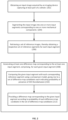
- FIG. 2 there is illustrated a generalized flowchart of vehicle image comparison in accordance with certain embodiments of the presently disclosed subject matter.
- An input image acquired by an imaging device can be obtained (e.g., by the PMC 102 via I/O interface 126, or from the image database 123, as illustrated in Fig. 1 ).
- the input image can capture at least part of a vehicle.
- input image or "target image” used herein should be expansively construed to refer to any of the following: one or more still images acquired from one or more perspectives, sequence/series of images/frames acquired from a given perspective constituting video(s), and stitched/composite image(s) generated based on any of the above.
- the input image can refer to one or more images captured by one image acquisition device from a given perspective/view/angle, such as, e.g., front, side (e.g., either left or right side), rear, top, and underside of a vehicle.
- the input image can therefore cover at least part of the vehicle exterior, depending on the specific perspective that the images are taken from, and the relative position between the image acquisition device and the vehicle.
- an imaging device that is embedded underground of a passage that a vehicle passes by can capture multiple undercarriage images at a given time interval (e.g., 100-250 frames per second).
- the multiple undercarriage images with overlapping field of view can be combined together to form a single stitched image of the vehicle undercarriage.
- a stitched image which typically has a relatively high resolution, can be used as the input image.
- such a stitched image can be a 3D image.
- the input image can refer to one or more images acquired by each of a plurality of imaging acquisition units located at different relative positions with respect to the vehicle.
- still images can be acquired from different perspectives, and a composite image can be generated based on the multiple still images, which can be used as the input image to system 100.
- a 3D vehicle model can be created and used as the input image.
- the 3D model, as well as the 3D image as mentioned above, can refer to a model or an image which contains additional information for each pixel indicating relative or absolute depth measure of the pixel with respect to the imaging device.
- a 3D model or image can be created based on the captured 2D images, and one or more synthesized 2D images can be extracted from the 3D model or image.
- Such synthesized 2D images can be used as input for the comparison system 100 as disclosed herein rather than the captured 2D images. This can be advantageous in some cases for the purpose of compensating perspective differences (i.e., differences caused by point of view), since the synthesized 2D images can be generated from an estimated perspective that is closer/similar to the reference images, therefore enabling reducing the FA type differences.
- the functionality of generation of the stitched image or composite image as described above, or at least part thereof, can be integrated within the PMC 102.
- such functionality can be possibly provided by the imaging device, and the stitched image or composite image can be sent to the PMC via the I/O interface.
- the input image can be segmented (204) (e.g., by the Segmentation module 106 of PMC 102) into one or more input segments corresponding to one or more mechanical components comprised in the at least part of the vehicle using a segmentation model.
- the partition of a vehicle into mechanical components may vary, e.g., it is possible that a certain mechanical component can be further partitioned into sub-components.
- the correspondence/mapping between the input segments and mechanical components are not fixed and can be adapted accordingly.
- one input segment can correspond to one or more mechanical components, or alternatively, one mechanical component can correspond to one or more input segments.
- the present disclosure is not limited by the specific partition of mechanical components and/or the correspondence between the input segments and mechanical components.
- Fig. 4 illustrates an example of an input image and corresponding segments in accordance with certain embodiments of the presently disclosed subject matter.
- the exemplary input image 404 captures the undercarriage of a vehicle.
- the input image 404 is segmented into multiple input segments as illustrated in 402.
- the segmentation is performed such that the segments in 402 correspond to the following exemplary mechanical components: exhaust, fuel tank, engine, wheel, suspension, and chassis, etc.
- the segment 406 for example, in the current example, there is one segment 406 corresponding to the entire exhaust component.
- the exhaust can be further divided into sub-components/parts, such as, e.g., one or more exhaust pipes, and the segment(s) can correspond to the sub-components, or to the entire component.
- the segmentation model can be based on machine learning.
- the segmentation model can be implemented as a segmentation deep learning model, such as, e.g., a deep learning neural network (also referred to as deep neural network, or DNN).
- the segmentation deep learning model can be deemed as being comprised in the Segmentation module 106 of PMC 102.
- DNN as referred to herein can refer to supervised or unsupervised DNN comprising a plurality of layers organized in accordance with respective DNN architecture.
- the layers of DNN can be organized in accordance with Convolutional Neural Network (CNN) architecture, Recurrent Neural Network architecture, Recursive Neural Networks architecture, GAN architecture or otherwise.
- CNN Convolutional Neural Network
- Recurrent Neural Network architecture Recurrent Neural Network
- Recursive Neural Networks architecture GAN architecture or otherwise.
- at least some of the layers can be organized in a plurality of DNN sub-networks.
- Each layer of DNN can include multiple basic computational elements (CE) typically referred to in the art as dimensions, neurons, or nodes.
- CE basic computational elements
- CEs of a given layer can be connected with CEs of a preceding layer and/or a subsequent layer. Each connection between the CE of a preceding layer and the CE of a subsequent layer is associated with a weighting value.
- a given CE can receive inputs from CEs of a previous layer via the respective connections, each given connection being associated with a weighting value which can be applied to the input of the given connection.
- the weighting values can determine the relative strength of the connections and thus the relative influence of the respective inputs on the output of the given CE.
- the given CE can be configured to compute an activation value (e.g. the weighted sum of the inputs) and further derive an output by applying an activation function to the computed activation.
- the activation function can be, for example, an identity function, a deterministic function (e.g., linear, sigmoid, threshold, or the like), a stochastic function or other suitable function.
- the output from the given CE can be transmitted to CEs of a subsequent layer via the respective connections.
- each connection at the output of a CE can be associated with a weighting value which can be applied to the output of the CE prior to being received as an input of a CE of a subsequent layer.
- weighting values there can be threshold values (including limiting functions) associated with the connections and CEs.
- the weighting and/or threshold values of a DNN can be initially selected prior to training, and can be further iteratively adjusted or modified during training to achieve an optimal set of weighting and/or threshold values in a trained DNN. After each iteration, a difference can be determined between the actual output produced by DNN and the target output associated with the respective training set of data. The difference can be referred to as an error value. Training can be determined to be complete when a cost function indicative of the error value is less than a predetermined value, or when a limited change in performance between iterations is achieved. Optionally, at least part of the DNN subnetworks (if any) can be trained separately prior to training the entire DNN.
- a set of DNN input data used to adjust the weights/thresholds of a deep neural network is referred to hereinafter as a training set or training dataset or training data.
- FIG. 3 there is illustrated a generalized flowchart of reference selection in accordance with certain embodiments of the presently disclosed subject matter.
- the set of reference images are selected using an instance descriptor.
- the instance descriptor can be a unique identifier of a vehicle instance in an image.
- the instance descriptor can be obtained/generated by using license plate recognition.
- a manual entry of a identifier can be used as an instance descriptor.
- a fingerprint representative of specific features of the vehicle instance in the image can be created and used as the instance descriptor.
- the specific features can refer to one or more structural characteristics of elements/components/patterns within the image, such as, e.g., shape, size, location of elements, and geometrical relations and relative positions between elements, etc.
- the location and time of the acquisition of the input image can also be used as part of the identifier information. Accordingly, a specific instance descriptor is obtained (301) for the input image using any of the above described methods.
- a search of the specific instance descriptor is performed (302) in the image database (e.g., the image database 123 in Fig. 1 ) where previous scans of various vehicle instances (i.e., candidate reference images) are stored together with their unique instance descriptors associated therewith.
- the search is to determine whether the specific vehicle instance in the input image (as represented by the specific instance descriptor) can be found ( 304 ) in the database. If the specific instance is found, a first set of images associated with the same specific instance descriptor, thus capturing the same vehicle instance, are retrieved and used (306) as reference images for comparison with the input image.
- a similarity metric can be used to seek for alternative or additional references (i.e., a second set of images capturing similar vehicle instances).
- an encoding model can be used (308) to obtain vector representation for each of the input image and candidate reference images.
- the encoding model can be based on machine learning.
- the encoding model can be implemented as an encoding deep learning model, such as, e.g., an encoding DNN.
- the encoding DNN can be deemed as being comprised in the Reference selection module 104 of PMC 102.
- the general description of DNN architecture and implementation is described in detail above and thus will not be repeated here for purpose of brevity and conciseness of the description.
- a second set of images capturing similar vehicle instances can be selected (310) using a similarity metric between the vector representation of the input image and each candidate reference image.
- the similarity metric can be any known measure or function that can be used to quantify the similarity between two objects/instances, such as, e.g., any distance functions (e.g., L1-norm, L2-norm, etc.).
- the encoding DNN can be trained and optimized such that the distance between vector representation of all similar instances is smaller than the distance to any non-similar instances.
- the input image can be regarded as acquired by the imaging device at a first imaging condition, and at least one reference image within the set of reference images can be regarded as acquired at a second imaging condition different from the first imaging condition, thereby causing false alarm (FA) difference between the input image and the at least one reference image resulting from difference between the first and second imaging conditions. Therefore, in order to achieve an ideal comparison result, it is needed to identify the DOI while excluding FA differences.
- FA false alarm
- the set of reference images as selected have been previously segmented into reference segments corresponding to the mechanical components as comprised therein, in some cases it is possible that the reference segments of a given reference image do not exactly correspond to the input segments of the input image. For instance, there may be one or more input segments that do not have corresponding reference segments, or vice versa. In such cases, it is needed to perform a matching between the reference segments and the input segments, and any discrepancies resulting from non-matching segments can be identified as DOI differences.
- any non-matching input segments e.g., missing or extra input segments in the input image as compared to the reference segments
- each reference image within the set comprises at least one reference segment corresponding to at least one input segment of the one or more input segments (as comprised in the input image).
- a respective set of corresponding reference segments are obtained for each input segment of the at least one input segment.
- At least one difference map corresponding to the at least one input segment can be generated (e.g., by the Comparison module 108 of PMC 102).
- generation of the at least one difference map can comprise, for each given input segment, comparing (210) the given input segment with each corresponding reference segment within the respective set of reference segments thereof using a comparison model, giving rise to a set of difference map candidates each indicating probability of presence of DOI between the given input segment and the corresponding reference segment, and providing (212) a difference map corresponding to the given input segment according to probability of each difference map candidate in the set of difference map candidates.
- the DOI refers to the type of differences that are of the user's interest.
- the DOI can be representative of physical change of the vehicle itself, including but not limited to damages such as e.g., scratches, anomalies such as suspected objects, color changes, etc.
- the difference map as obtained in 212 can provide an indication of probability of presence of DOI in the given input segment.
- the comparison model can be based on machine learning.
- the comparison model can be implemented as a comparison deep learning model, such as, e.g., a comparison DNN.
- the comparison DNN can be implemented as a Siamese neutral network.
- the comparison DNN can be deemed as being comprised in the comparison module 108 of PMC 102.
- the comparison DNN can be trained using a training dataset comprising a set of image pairs each including a target image and a reference image for which DOI differences are pre-identified.
- the model is trained so as to be capable of identifying DOI and excluding the FA difference in a difference map generated between each image pair.
- target images as provided to the training process can include synthetic simulated images. The simulated images are generated for the purpose of simulating different kinds of DOIs to be embedded in the target images, such as suspected objects, etc., so that the model can be trained to identify such anomalies in runtime.
- each difference map candidate in the set of difference map candidates can indicate segment-wise probability of presence of DOI between the given input segment and the corresponding reference segment.
- the difference map as provided in block 212 is selected from the set of difference map candidates according to ranking of the probability of each difference map candidate in the set.
- the segment-wise probability can be represented by a numerical value within a range of [0, 1] for each given segment, with 1 indicating most likely there is presence of DOI in the given input segment and 0 indicating otherwise. It is appreciated that other kinds of representation of probability and/or ranges can be used in lieu of the above.
- each difference map candidate in the set of difference map candidates can indicate pixel-wise probability of presence of DOI between the given input segment and the corresponding reference segment.
- the difference map as provided in block 212 can be generated based on the set of difference map candidates.
- Each pixel value in the difference map can be determined based on a corresponding pixel value in each difference map candidate in the set.
- the pixel-wise probability can be represented by a numerical value within a range of [0, 1] for each pixel in the given input segment, with 1 indicating most likely there is presence of DOI in the given pixel and 0 indicating otherwise.
- a given pixel value in the difference map can be selected, from all corresponding pixel values in the difference map candidates, as the pixel value that indicates a best probability.
- the pixel value can be generated using an averaging algorithm on all or some of the corresponding pixel values.
- the averaging algorithm can be based on any known averaging schemes which can average among a set of values, such as, mean, median, mode, etc.
- the difference map as generated for each input segment can be a composite comparison result in which at least some of the pixels result from comparisons with different reference images.
- each pixel in the difference map results from a comparison with a corresponding pixel in a respective reference segment that gives the best probability.
- each pixel can be selected from five corresponding pixels in the five candidates, or generated based on the five corresponding pixel values.
- pixel 1 is selected from a corresponding pixel in candidate 3 which resulted from comparison with reference 3, since that pixel indicates a best probability of DOI, while pixel 2 may be selected from a corresponding pixel in candidate 5 which resulted from comparison with reference 5, etc.
- each difference map of the at least one difference map can be either presented to the user (e.g., through the GUI 124) individually, or alternatively, the at least one difference map can be combined to a composite difference map indicating probability of presence of DOI in the entire input image, and the composite difference map can be presented to the user.
- these non-matching input segments can be combined with the composite difference map and provided to the user to review.
- Fig. 5 illustrates an example of a composite difference map and a corresponding input image in accordance with certain embodiments of the presently disclosed subject matter.
- one or more difference maps corresponding to segments/components are generated and then combined into a composite difference map 502.
- two DOIs 506 and 508 can be identified from the composite difference map which correspond to two suspected objects in the input image (as squared).
- the system according to the invention may be, at least partly, implemented on a suitably programmed computer.
- the invention contemplates a computer program being readable by a computer for executing the method of the invention.
- the invention further contemplates a non-transitory computer readable memory or storage medium tangibly embodying a program of instructions executable by the computer for executing the method of the invention.
- the non-transitory computer readable storage medium causing a processor to carry out aspects of the present invention can be a tangible device that can retain and store instructions for use by an instruction execution device.
- the computer readable storage medium may be, for example, but is not limited to, an electronic storage device, a magnetic storage device, an optical storage device, an electromagnetic storage device, a semiconductor storage device, or any suitable combination of the foregoing.
Landscapes
- Engineering & Computer Science (AREA)
- Theoretical Computer Science (AREA)
- Physics & Mathematics (AREA)
- General Physics & Mathematics (AREA)
- Computer Vision & Pattern Recognition (AREA)
- Evolutionary Computation (AREA)
- Multimedia (AREA)
- Artificial Intelligence (AREA)
- Health & Medical Sciences (AREA)
- General Health & Medical Sciences (AREA)
- Software Systems (AREA)
- Computing Systems (AREA)
- Databases & Information Systems (AREA)
- Medical Informatics (AREA)
- Life Sciences & Earth Sciences (AREA)
- Data Mining & Analysis (AREA)
- Quality & Reliability (AREA)
- Biomedical Technology (AREA)
- Molecular Biology (AREA)
- Biodiversity & Conservation Biology (AREA)
- Probability & Statistics with Applications (AREA)
- Bioinformatics & Cheminformatics (AREA)
- Bioinformatics & Computational Biology (AREA)
- Evolutionary Biology (AREA)
- General Engineering & Computer Science (AREA)
- Image Analysis (AREA)
- Traffic Control Systems (AREA)
- Image Processing (AREA)
Claims (15)
- Rechnergestütztes Verfahren zum Vergleichen von Fahrzeugbildern, das Folgendes umfasst:Erhalten (202) eines Eingangsbildes, das von einer Bildgebungsvorrichtung erfasst wird, die zumindest einen Teil eines Fahrzeugs erfasst;Segmentieren (204) des Eingangsbildes in ein oder mehrere Eingangssegmente, die einer oder mehreren mechanischen Komponenten entsprechen, die in dem mindestens einen Teil des Fahrzeugs enthalten sind, unter Verwendung eines Segmentierungsmodells;Abrufen (206) eines Satzes von mehreren Referenzbildern, wobei jedes Referenzbild innerhalb des Satzes mindestens ein Referenzsegment umfasst, das mindestens einem Eingangssegment des einen oder der mehreren Eingangssegmente entspricht, wodurch ein entsprechender Satz von mehreren entsprechenden Referenzsegmenten für jedes Eingangssegment des mindestens einen Eingangssegments erhalten wird; undErzeugen (208) mindestens einer Differenzkarte, die dem mindestens einen Eingangssegment entspricht, für jedes gegebene Eingangssegment des mindestens einen Eingangssegments umfassend:Vergleichen (210) des gegebenen Eingangssegments jeweils mit jedem entsprechenden Referenzsegment innerhalb des jeweiligen Satzes von mehreren entsprechenden Referenzsegmenten davon unter Verwendung eines Vergleichsmodells, was zu einem Satz von mehreren Differenzkartenkandidaten führt, die jeweils die Wahrscheinlichkeit des Vorhandenseins einer interessierenden Differenz (DOI) zwischen dem gegebenen Eingangssegment und dem entsprechenden Referenzsegment anzeigen, wobei die DOI eine physikalische Veränderung des Fahrzeugs darstellt; undBereitstellen (212) einer Differenzkarte, die dem gegebenen Eingangssegment entspricht, gemäß der Wahrscheinlichkeit jedes Differenzkartenkandidaten in dem Satz von mehreren Differenzkartenkandidaten, wobei die Differenzkarte die Wahrscheinlichkeit des Vorhandenseins einer DOI in dem gegebenen Eingangssegment anzeigt.
- Rechnergestütztes Verfahren nach Anspruch 1, ferner umfassend das Kombinieren jeder der mindestens einen Differenzkarte, die dem mindestens einen Eingangssegment entspricht, zu einer zusammengesetzten Differenzkarte, die die Wahrscheinlichkeit des Vorhandenseins einer DOI in dem mindestens einen Eingangssegment in dem Eingangsbild anzeigt.
- Rechnergestütztes Verfahren nach Anspruch 1, wobei das Eingangsbild von der Bildgebungsvorrichtung unter einer ersten Bildgebungsbedingung erfasst wird und wobei mindestens ein Referenzbild innerhalb des Satzes von mehreren Referenzbildern unter einer zweiten Bildgebungsbedingung erfasst wird, die sich von der ersten Bildgebungsbedingung unterscheidet, wodurch eine Fehlalarmdifferenz (FA) zwischen dem Eingangsbild und dem mindestens einen Referenzbild verursacht wird, die sich aus der Differenz zwischen der ersten und der zweiten Bildgebungsbedingung ergibt.
- Rechnergestütztes Verfahren nach Anspruch 3, wobei die ersten und zweiten Bildgebungsbedingungen eine oder mehrere der folgenden Bedingungen umfassen: relative Position zwischen dem Fahrzeug und der Bildgebungsvorrichtung, Beleuchtungszustand und Geschwindigkeit des Fahrzeugs.
- Rechnergestütztes Verfahren nach Anspruch 1, wobei der Satz von mehreren Referenzbildern unter Verwendung eines Instanzdeskriptors abgerufen wird, der das Fahrzeug im Eingangsbild eindeutig identifiziert.
- Rechnergestütztes Verfahren nach Anspruch 5, wobei der Satz von mehreren Referenzbildern aus einer Gruppe ausgewählt wird, die Folgendes umfasst: einen ersten Satz von Bildern, die denselben Fall des Fahrzeugs erfassen, und einen zweiten Satz von Bildern, die ähnliche Fälle des Fahrzeugs erfassen.
- Rechnergestütztes Verfahren nach Anspruch 6, wobei der zweite Satz von Bildern ausgewählt wird durch: Verwenden (308) eines Codierungsmodells, um eine Vektordarstellung für jedes des Eingangsbildes und der Kandidaten-Referenzbilder zu erhalten, und Auswählen (310) des zweiten Satzes von Bildern unter Verwendung einer Ähnlichkeitsmetrik zwischen der Vektordarstellung des Eingangsbildes und jedem Kandidaten-Referenzbild.
- Rechnergestütztes Verfahren nach Anspruch 1, wobei das Segmentierungsmodell ein Deep-Learning-Segmentierungsmodell ist, das unter Verwendung eines Trainingsdatensatzes trainiert wurde, der einen Satz von vorsegmentierten Fahrzeugbildern entsprechend den darin enthaltenen mechanischen Komponenten umfasst.
- Rechnergestütztes Verfahren nach Anspruch 1, wobei das Vergleichsmodell ein vergleichendes Deep-Learning-Modell ist, das unter Verwendung eines Trainingsdatensatzes trainiert wurde, der einen Satz von Bildpaaren umfasst, die jeweils ein Zielbild und ein Referenzbild enthalten, um in der Lage zu sein, die DOI zu identifizieren und die FA-Differenz in einer Differenzkarte zwischen jedem Bildpaar auszuschließen.
- Rechnergestütztes Verfahren nach Anspruch 1, wobei jeder Differenzkartenkandidat in dem Satz von mehreren Differenzkartenkandidaten die segmentweise Wahrscheinlichkeit des Vorhandenseins einer DOI zwischen dem gegebenen Eingangssegment und dem entsprechenden Referenzsegment angibt, und wobei das Bereitstellen das Auswählen einer Differenzkarte aus dem Satz von mehreren Differenzkartenkandidaten gemäß der Rangfolge der Wahrscheinlichkeit jedes Differenzkartenkandidaten in dem Satz umfasst.
- Rechnergestütztes Verfahren nach Anspruch 1, wobei jeder Differenzkartenkandidat in dem Satz von mehreren Differenzkartenkandidaten die pixelweise Wahrscheinlichkeit des Vorhandenseins einer DOI zwischen dem gegebenen Eingangssegment und dem entsprechenden Referenzsegment angibt, und wobei das Bereitstellen das Erzeugen einer Differenzkarte umfasst, in der jeder Pixelwert auf der Grundlage eines entsprechenden Pixelwertes in jedem Differenzkartenkandidaten in dem Satz bestimmt wird.
- Rechnergestütztes Verfahren nach Anspruch 11, wobei mindestens einige der Pixel in der Differenzkarte aus Vergleichen mit verschiedenen Referenzbildern resultieren.
- Rechnergestütztes Verfahren nach Anspruch 1, wobei jedes Referenzbild innerhalb des Satzes ein oder mehrere Referenzsegmente umfasst, und das Verfahren ferner für jedes Referenzbild das Durchführen eines Abgleichs zwischen den Eingangssegmenten und den Referenzsegmenten umfasst, um das mindestens eine Referenzsegment zu identifizieren, das dem mindestens einen Eingangssegment entspricht.
- Rechnergestütztes System zum Vergleichen von Fahrzeugbildern, wobei das System einen Prozessor und eine Speicherschaltung (102) umfasst, die betriebsmäßig mit einer E/A-Schnittstelle (126) verbunden ist, wobei das System so konfiguriert ist, dass es das Verfahren nach einem der Ansprüche 1 bis 13 durchführt.
- Nicht transitorisches, computerlesbares Medium, das Befehle umfasst, die, wenn sie von einem Rechner ausgeführt werden, den Rechner veranlassen, das Verfahren nach einem der Ansprüche 1 bis 13 auszuführen.
Applications Claiming Priority (2)
| Application Number | Priority Date | Filing Date | Title |
|---|---|---|---|
| US15/940,172 US10650530B2 (en) | 2018-03-29 | 2018-03-29 | Method of vehicle image comparison and system thereof |
| PCT/IL2019/050327 WO2019186531A1 (en) | 2018-03-29 | 2019-03-24 | Method of vehicle image comparison and system thereof |
Publications (3)
| Publication Number | Publication Date |
|---|---|
| EP3776449A1 EP3776449A1 (de) | 2021-02-17 |
| EP3776449A4 EP3776449A4 (de) | 2021-12-29 |
| EP3776449B1 true EP3776449B1 (de) | 2025-06-25 |
Family
ID=68057109
Family Applications (1)
| Application Number | Title | Priority Date | Filing Date |
|---|---|---|---|
| EP19776128.1A Active EP3776449B1 (de) | 2018-03-29 | 2019-03-24 | Verfahren zum fahrzeugbildvergleich und system dafür |
Country Status (5)
| Country | Link |
|---|---|
| US (1) | US10650530B2 (de) |
| EP (1) | EP3776449B1 (de) |
| JP (1) | JP7130216B2 (de) |
| KR (1) | KR102505545B1 (de) |
| WO (1) | WO2019186531A1 (de) |
Families Citing this family (21)
| Publication number | Priority date | Publication date | Assignee | Title |
|---|---|---|---|---|
| JP7258509B2 (ja) * | 2018-10-15 | 2023-04-17 | オムロン株式会社 | 画像処理装置、画像処理方法、及び画像処理プログラム |
| US11935222B2 (en) * | 2018-12-13 | 2024-03-19 | Uveye Ltd. | Method of automatic tire inspection and system thereof |
| US11770493B2 (en) | 2019-04-02 | 2023-09-26 | ACV Auctions Inc. | Vehicle undercarriage imaging system |
| KR102804886B1 (ko) * | 2019-06-14 | 2025-05-09 | 현대자동차주식회사 | 엔진 상태 진단 방법 |
| US11024034B2 (en) * | 2019-07-02 | 2021-06-01 | Acist Medical Systems, Inc. | Image segmentation confidence determination |
| JP7509153B2 (ja) * | 2019-11-11 | 2024-07-02 | 株式会社レゾナック | 情報処理システム、情報処理方法、および情報処理プログラム |
| US11461890B2 (en) | 2020-02-05 | 2022-10-04 | Fulpruf Technology Corporation | Vehicle supply chain damage tracking system |
| US11430143B2 (en) | 2020-06-10 | 2022-08-30 | Uveye Ltd. | System of depth estimation and method thereof |
| DE102020122304A1 (de) * | 2020-08-26 | 2022-03-03 | Deere & Company | Verfahren zur Überprüfung eines Zustandes einer mobilen Nutzeinheit oder einer Wartungsstation |
| JP7795746B2 (ja) * | 2020-09-23 | 2026-01-08 | ユーヴイアイ リミテッド | 車両画像分析 |
| DE102020127743A1 (de) | 2020-10-21 | 2022-04-21 | Deere & Company | Verfahren zur Versorgung einer mobilen Nutzeinheit mit einem Verbrauchstoff |
| DE102020127739A1 (de) | 2020-10-21 | 2022-04-21 | Deere & Company | Verfahren zur Überprüfung eines Fehlerzustandes einer mobilen Nutzeinheit |
| KR20220130398A (ko) | 2021-03-18 | 2022-09-27 | 현대자동차주식회사 | 차량 검사 장치 및 차량의 검사 방법 |
| CN113361989A (zh) * | 2021-05-07 | 2021-09-07 | 深圳依时货拉拉科技有限公司 | 货物识别方法、计算机设备和货物监控系统 |
| DE102021116068A1 (de) | 2021-06-22 | 2022-12-22 | Zf Cv Systems Global Gmbh | Verfahren zum Inspizieren eines Fahrzeuges und Inspektions-System |
| US12207415B2 (en) | 2021-11-29 | 2025-01-21 | Hewlett Packard Enterprise Development Lp | Identifications of deviations relating to assemblies of components |
| US20250157211A1 (en) * | 2022-02-08 | 2025-05-15 | Telefonaktiebolaget Lm Ericsson (Publ) | Method and apparatus for detecting changes in an enviroment |
| JP2023174362A (ja) * | 2022-05-27 | 2023-12-07 | 国立大学法人福井大学 | 画像異常検知プログラム、情報処理装置、画像異常検知方法及び製造方法 |
| WO2025164244A1 (ja) * | 2024-01-30 | 2025-08-07 | パナソニックIpマネジメント株式会社 | 車体状態推定システム、車体状態推定方法及びプログラム |
| US12140501B1 (en) * | 2024-03-22 | 2024-11-12 | Uveye Ltd. | Single pass automated vehicle inspection system and method |
| US12392730B1 (en) | 2024-08-30 | 2025-08-19 | ACV Auctions Inc. | Systems and techniques for vehicle inspection and condition analysis |
Family Cites Families (30)
| Publication number | Priority date | Publication date | Assignee | Title |
|---|---|---|---|---|
| US4807787A (en) | 1987-05-12 | 1989-02-28 | The Procter & Gamble Company | Easy-open/reclosure device having deformable pour spout |
| JPH10213422A (ja) * | 1997-01-29 | 1998-08-11 | Hitachi Ltd | パタ−ン検査装置 |
| JP4035974B2 (ja) * | 2001-09-26 | 2008-01-23 | 株式会社日立製作所 | 欠陥観察方法及びその装置 |
| JP3669698B2 (ja) * | 2002-09-20 | 2005-07-13 | 日東電工株式会社 | 印刷物の検査方法及び検査装置 |
| JP2004199236A (ja) | 2002-12-17 | 2004-07-15 | Toyota Motor Corp | 修理見積作成装置、修理見積システム及び修理見積方法 |
| US20060171593A1 (en) * | 2005-02-01 | 2006-08-03 | Hitachi High-Technologies Corporation | Inspection apparatus for inspecting patterns of a substrate |
| US20130188878A1 (en) * | 2010-07-20 | 2013-07-25 | Lockheed Martin Corporation | Image analysis systems having image sharpening capabilities and methods using same |
| WO2012012576A1 (en) | 2010-07-20 | 2012-01-26 | Lockheed Martin Corporation | Image analysis systems using non-linear data processing techniques and methods using same |
| JP5840940B2 (ja) * | 2011-12-16 | 2016-01-06 | パナソニック インテレクチュアル プロパティ コーポレーション オブアメリカPanasonic Intellectual Property Corporation of America | 画像領域抽出装置、画像領域抽出方法、および画像領域抽出プログラム |
| US8995718B2 (en) * | 2012-10-11 | 2015-03-31 | Ittiam Systems (P) Ltd. | System and method for low complexity change detection in a sequence of images through background estimation |
| JP6362333B2 (ja) * | 2013-02-14 | 2018-07-25 | キヤノン株式会社 | 画像処理装置、画像処理方法、およびプログラム |
| EP2911112B1 (de) * | 2014-02-21 | 2019-04-17 | Wipro Limited | Verfahren zur Beurteilung einer Bildveränderung und Vorrichtungen dafür |
| US9153079B1 (en) | 2014-03-18 | 2015-10-06 | Robert Bruce Wood | System and method of automated 3D scanning for vehicle maintenance |
| US20150294182A1 (en) * | 2014-04-13 | 2015-10-15 | Samsung Electronics Co., Ltd. | Systems and methods for estimation of objects from an image |
| CN105787495A (zh) | 2014-12-17 | 2016-07-20 | 同方威视技术股份有限公司 | 具有车辆参考图像检索及比对功能的车辆检查系统和方法 |
| SE538405C2 (en) * | 2015-01-07 | 2016-06-14 | Viscando Ab | Method and system for categorization of a scene |
| US9232118B1 (en) * | 2015-01-23 | 2016-01-05 | Interra Systems, Inc | Methods and systems for detecting video artifacts |
| EP3176751B1 (de) | 2015-12-01 | 2020-12-30 | Ricoh Company, Ltd. | Informationsverarbeitungsvorrichtung, informationsverarbeitungsverfahren, computerlesbares aufzeichnungsmedium und prüfsystem |
| CN106991423B (zh) * | 2016-01-21 | 2019-06-07 | 腾讯科技(深圳)有限公司 | 识别规格图片中是否包含水印的方法及装置 |
| US9773196B2 (en) | 2016-01-25 | 2017-09-26 | Adobe Systems Incorporated | Utilizing deep learning for automatic digital image segmentation and stylization |
| US10692050B2 (en) | 2016-04-06 | 2020-06-23 | American International Group, Inc. | Automatic assessment of damage and repair costs in vehicles |
| US9886771B1 (en) * | 2016-05-20 | 2018-02-06 | Ccc Information Services Inc. | Heat map of vehicle damage |
| US10298864B2 (en) * | 2016-06-10 | 2019-05-21 | Apple Inc. | Mismatched foreign light detection and mitigation in the image fusion of a two-camera system |
| CN106127747B (zh) | 2016-06-17 | 2018-10-16 | 史方 | 基于深度学习的汽车表面损伤分类方法及装置 |
| US10043088B2 (en) * | 2016-06-23 | 2018-08-07 | Siemens Healthcare Gmbh | Image quality score using a deep generative machine-learning model |
| CN109690554B (zh) * | 2016-07-21 | 2023-12-05 | 西门子保健有限责任公司 | 用于基于人工智能的医学图像分割的方法和系统 |
| JP6694362B2 (ja) * | 2016-09-30 | 2020-05-13 | 富士フイルム株式会社 | 画像検査方法及び装置、プログラム並びに画像記録システム |
| US10282843B2 (en) * | 2016-10-27 | 2019-05-07 | International Business Machines Corporation | System and method for lesion analysis and recommendation of screening checkpoints for reduced risk of skin cancer |
| US10255526B2 (en) * | 2017-06-09 | 2019-04-09 | Uptake Technologies, Inc. | Computer system and method for classifying temporal patterns of change in images of an area |
| US10726307B2 (en) * | 2017-06-30 | 2020-07-28 | Ai Systems Co., Ltd. | Real-time identification of moving objects in video images |
-
2018
- 2018-03-29 US US15/940,172 patent/US10650530B2/en active Active
-
2019
- 2019-03-24 WO PCT/IL2019/050327 patent/WO2019186531A1/en not_active Ceased
- 2019-03-24 EP EP19776128.1A patent/EP3776449B1/de active Active
- 2019-03-24 KR KR1020207029248A patent/KR102505545B1/ko active Active
- 2019-03-24 JP JP2021501138A patent/JP7130216B2/ja active Active
Also Published As
| Publication number | Publication date |
|---|---|
| JP2021520007A (ja) | 2021-08-12 |
| WO2019186531A1 (en) | 2019-10-03 |
| US10650530B2 (en) | 2020-05-12 |
| EP3776449A4 (de) | 2021-12-29 |
| EP3776449A1 (de) | 2021-02-17 |
| US20190304100A1 (en) | 2019-10-03 |
| KR20210006335A (ko) | 2021-01-18 |
| JP7130216B2 (ja) | 2022-09-05 |
| KR102505545B1 (ko) | 2023-03-03 |
Similar Documents
| Publication | Publication Date | Title |
|---|---|---|
| US10650530B2 (en) | Method of vehicle image comparison and system thereof | |
| EP3776450B1 (de) | Verfahren zum vergleich von fahrzeugbildern und system dafür | |
| US11430143B2 (en) | System of depth estimation and method thereof | |
| CN109271908B (zh) | 车损检测方法、装置及设备 | |
| CN111126393A (zh) | 车辆外观改装判断方法、装置、计算机设备及存储介质 | |
| JP7795746B2 (ja) | 車両画像分析 | |
| Du et al. | Dynamic pavement distress image stitching based on fine‐grained feature matching | |
| Liu et al. | Container-code recognition system based on computer vision and deep neural networks | |
| Adu-Gyamfi et al. | Functional evaluation of pavement condition using a complete vision system | |
| IL293594A (en) | Systems, methods and programs for generating damage print in a vehicle | |
| CN111402185B (zh) | 一种图像检测方法及装置 | |
| CN111325076A (zh) | 一种基于U-net与Seg-net网络融合的航空地面建筑物提取方法 | |
| CN119599986B (zh) | 一种基于深度学习的道路附属设施缺陷检测方法及系统 | |
| CN121582336B (zh) | 一种面向动态场景下深度约束的机器人算法、存储介质及设备 | |
| Ishida et al. | Generation of free-viewpoint images reflecting damage detection results using deep learning | |
| Bachmann et al. | An iterative scheme for motion-based scene segmentation | |
| CN118864965A (zh) | 一种动车组车体零部件异常检测方法、装置、设备及存储介质 | |
| CN120931565A (zh) | 车辆外观损伤自动检测方法及系统 | |
| HK40003573A (en) | Vehicle damage detection method, device and apparatus | |
| CN119722784A (zh) | 一种罐装车加注口位姿定位方法及存储介质 | |
| CN119360136A (zh) | 一种基于机器视觉的车底部件异常检测方法及系统 | |
| Paudel et al. | Optimal Transformation Estimation with Semantic Cues | |
| CN117218561A (zh) | 一种基于多源遥感的自然资源登记方法 | |
| CN115700814A (zh) | 停车位检测方法、装置、计算机设备和存储介质 | |
| Zhu et al. | A novel method for exactly locating road intersections in aerial images |
Legal Events
| Date | Code | Title | Description |
|---|---|---|---|
| STAA | Information on the status of an ep patent application or granted ep patent |
Free format text: STATUS: THE INTERNATIONAL PUBLICATION HAS BEEN MADE |
|
| PUAI | Public reference made under article 153(3) epc to a published international application that has entered the european phase |
Free format text: ORIGINAL CODE: 0009012 |
|
| STAA | Information on the status of an ep patent application or granted ep patent |
Free format text: STATUS: REQUEST FOR EXAMINATION WAS MADE |
|
| 17P | Request for examination filed |
Effective date: 20201029 |
|
| AK | Designated contracting states |
Kind code of ref document: A1 Designated state(s): AL AT BE BG CH CY CZ DE DK EE ES FI FR GB GR HR HU IE IS IT LI LT LU LV MC MK MT NL NO PL PT RO RS SE SI SK SM TR |
|
| AX | Request for extension of the european patent |
Extension state: BA ME |
|
| DAV | Request for validation of the european patent (deleted) | ||
| DAX | Request for extension of the european patent (deleted) | ||
| A4 | Supplementary search report drawn up and despatched |
Effective date: 20211201 |
|
| RIC1 | Information provided on ipc code assigned before grant |
Ipc: G06K 9/62 20060101ALI20211125BHEP Ipc: G06K 9/32 20060101ALI20211125BHEP Ipc: G06Q 10/00 20120101ALI20211125BHEP Ipc: G06K 9/66 20060101ALI20211125BHEP Ipc: G06K 9/46 20060101ALI20211125BHEP Ipc: G06T 7/11 20170101ALI20211125BHEP Ipc: G06T 7/00 20170101ALI20211125BHEP Ipc: G06T 1/00 20060101AFI20211125BHEP |
|
| 111Z | Information provided on other rights and legal means of execution |
Free format text: AL AT BE BG CH CY CZ DE DK EE ES FI FR GB GR HR HU IE IS IT LT LU LV MC MK MT NL NO PL PT RO RS SE SI SK SM TR Effective date: 20230811 |
|
| GRAP | Despatch of communication of intention to grant a patent |
Free format text: ORIGINAL CODE: EPIDOSNIGR1 |
|
| STAA | Information on the status of an ep patent application or granted ep patent |
Free format text: STATUS: GRANT OF PATENT IS INTENDED |
|
| RIC1 | Information provided on ipc code assigned before grant |
Ipc: G06V 10/82 20220101ALI20241231BHEP Ipc: G06V 10/74 20220101ALI20241231BHEP Ipc: G06V 10/44 20220101ALI20241231BHEP Ipc: G06V 10/25 20220101ALI20241231BHEP Ipc: G06F 18/22 20230101ALI20241231BHEP Ipc: G06T 7/11 20170101ALI20241231BHEP Ipc: G06T 7/00 20170101ALI20241231BHEP Ipc: G06T 1/00 20060101AFI20241231BHEP |
|
| INTG | Intention to grant announced |
Effective date: 20250121 |
|
| D11X | Information provided on other rights and legal means of execution (deleted) | ||
| GRAS | Grant fee paid |
Free format text: ORIGINAL CODE: EPIDOSNIGR3 |
|
| GRAA | (expected) grant |
Free format text: ORIGINAL CODE: 0009210 |
|
| STAA | Information on the status of an ep patent application or granted ep patent |
Free format text: STATUS: THE PATENT HAS BEEN GRANTED |
|
| AK | Designated contracting states |
Kind code of ref document: B1 Designated state(s): AL AT BE BG CH CY CZ DE DK EE ES FI FR GB GR HR HU IE IS IT LI LT LU LV MC MK MT NL NO PL PT RO RS SE SI SK SM TR |
|
| REG | Reference to a national code |
Ref country code: GB Ref legal event code: FG4D |
|
| REG | Reference to a national code |
Ref country code: CH Ref legal event code: EP |
|
| REG | Reference to a national code |
Ref country code: CH Ref legal event code: EP |
|
| REG | Reference to a national code |
Ref country code: IE Ref legal event code: FG4D |
|
| REG | Reference to a national code |
Ref country code: DE Ref legal event code: R096 Ref document number: 602019071602 Country of ref document: DE |
|
| PG25 | Lapsed in a contracting state [announced via postgrant information from national office to epo] |
Ref country code: FI Free format text: LAPSE BECAUSE OF FAILURE TO SUBMIT A TRANSLATION OF THE DESCRIPTION OR TO PAY THE FEE WITHIN THE PRESCRIBED TIME-LIMIT Effective date: 20250625 |
|
| REG | Reference to a national code |
Ref country code: LT Ref legal event code: MG9D |
|
| PG25 | Lapsed in a contracting state [announced via postgrant information from national office to epo] |
Ref country code: NO Free format text: LAPSE BECAUSE OF FAILURE TO SUBMIT A TRANSLATION OF THE DESCRIPTION OR TO PAY THE FEE WITHIN THE PRESCRIBED TIME-LIMIT Effective date: 20250925 Ref country code: GR Free format text: LAPSE BECAUSE OF FAILURE TO SUBMIT A TRANSLATION OF THE DESCRIPTION OR TO PAY THE FEE WITHIN THE PRESCRIBED TIME-LIMIT Effective date: 20250926 |
|
| PG25 | Lapsed in a contracting state [announced via postgrant information from national office to epo] |
Ref country code: BG Free format text: LAPSE BECAUSE OF FAILURE TO SUBMIT A TRANSLATION OF THE DESCRIPTION OR TO PAY THE FEE WITHIN THE PRESCRIBED TIME-LIMIT Effective date: 20250625 |
|
| PG25 | Lapsed in a contracting state [announced via postgrant information from national office to epo] |
Ref country code: HR Free format text: LAPSE BECAUSE OF FAILURE TO SUBMIT A TRANSLATION OF THE DESCRIPTION OR TO PAY THE FEE WITHIN THE PRESCRIBED TIME-LIMIT Effective date: 20250625 |
|
| PG25 | Lapsed in a contracting state [announced via postgrant information from national office to epo] |
Ref country code: RS Free format text: LAPSE BECAUSE OF FAILURE TO SUBMIT A TRANSLATION OF THE DESCRIPTION OR TO PAY THE FEE WITHIN THE PRESCRIBED TIME-LIMIT Effective date: 20250925 |
|
| PG25 | Lapsed in a contracting state [announced via postgrant information from national office to epo] |
Ref country code: LV Free format text: LAPSE BECAUSE OF FAILURE TO SUBMIT A TRANSLATION OF THE DESCRIPTION OR TO PAY THE FEE WITHIN THE PRESCRIBED TIME-LIMIT Effective date: 20250625 |
|
| REG | Reference to a national code |
Ref country code: NL Ref legal event code: MP Effective date: 20250625 |
|
| PG25 | Lapsed in a contracting state [announced via postgrant information from national office to epo] |
Ref country code: NL Free format text: LAPSE BECAUSE OF FAILURE TO SUBMIT A TRANSLATION OF THE DESCRIPTION OR TO PAY THE FEE WITHIN THE PRESCRIBED TIME-LIMIT Effective date: 20250625 |
|
| PG25 | Lapsed in a contracting state [announced via postgrant information from national office to epo] |
Ref country code: PT Free format text: LAPSE BECAUSE OF FAILURE TO SUBMIT A TRANSLATION OF THE DESCRIPTION OR TO PAY THE FEE WITHIN THE PRESCRIBED TIME-LIMIT Effective date: 20251027 |
|
| REG | Reference to a national code |
Ref country code: AT Ref legal event code: MK05 Ref document number: 1807298 Country of ref document: AT Kind code of ref document: T Effective date: 20250625 |
|
| PG25 | Lapsed in a contracting state [announced via postgrant information from national office to epo] |
Ref country code: IS Free format text: LAPSE BECAUSE OF FAILURE TO SUBMIT A TRANSLATION OF THE DESCRIPTION OR TO PAY THE FEE WITHIN THE PRESCRIBED TIME-LIMIT Effective date: 20251025 |
|
| PG25 | Lapsed in a contracting state [announced via postgrant information from national office to epo] |
Ref country code: AT Free format text: LAPSE BECAUSE OF FAILURE TO SUBMIT A TRANSLATION OF THE DESCRIPTION OR TO PAY THE FEE WITHIN THE PRESCRIBED TIME-LIMIT Effective date: 20250625 Ref country code: SM Free format text: LAPSE BECAUSE OF FAILURE TO SUBMIT A TRANSLATION OF THE DESCRIPTION OR TO PAY THE FEE WITHIN THE PRESCRIBED TIME-LIMIT Effective date: 20250625 |
|
| PG25 | Lapsed in a contracting state [announced via postgrant information from national office to epo] |
Ref country code: CZ Free format text: LAPSE BECAUSE OF FAILURE TO SUBMIT A TRANSLATION OF THE DESCRIPTION OR TO PAY THE FEE WITHIN THE PRESCRIBED TIME-LIMIT Effective date: 20250625 |
|
| PG25 | Lapsed in a contracting state [announced via postgrant information from national office to epo] |
Ref country code: PL Free format text: LAPSE BECAUSE OF FAILURE TO SUBMIT A TRANSLATION OF THE DESCRIPTION OR TO PAY THE FEE WITHIN THE PRESCRIBED TIME-LIMIT Effective date: 20250625 |
|
| PG25 | Lapsed in a contracting state [announced via postgrant information from national office to epo] |
Ref country code: EE Free format text: LAPSE BECAUSE OF FAILURE TO SUBMIT A TRANSLATION OF THE DESCRIPTION OR TO PAY THE FEE WITHIN THE PRESCRIBED TIME-LIMIT Effective date: 20250625 |
|
| PG25 | Lapsed in a contracting state [announced via postgrant information from national office to epo] |
Ref country code: SK Free format text: LAPSE BECAUSE OF FAILURE TO SUBMIT A TRANSLATION OF THE DESCRIPTION OR TO PAY THE FEE WITHIN THE PRESCRIBED TIME-LIMIT Effective date: 20250625 |
|
| PG25 | Lapsed in a contracting state [announced via postgrant information from national office to epo] |
Ref country code: ES Free format text: LAPSE BECAUSE OF FAILURE TO SUBMIT A TRANSLATION OF THE DESCRIPTION OR TO PAY THE FEE WITHIN THE PRESCRIBED TIME-LIMIT Effective date: 20250625 |
|
| PGFP | Annual fee paid to national office [announced via postgrant information from national office to epo] |
Ref country code: GB Payment date: 20260304 Year of fee payment: 8 |
|
| PG25 | Lapsed in a contracting state [announced via postgrant information from national office to epo] |
Ref country code: DK Free format text: LAPSE BECAUSE OF FAILURE TO SUBMIT A TRANSLATION OF THE DESCRIPTION OR TO PAY THE FEE WITHIN THE PRESCRIBED TIME-LIMIT Effective date: 20250625 |
|
| PGFP | Annual fee paid to national office [announced via postgrant information from national office to epo] |
Ref country code: DE Payment date: 20260320 Year of fee payment: 8 |
|
| PG25 | Lapsed in a contracting state [announced via postgrant information from national office to epo] |
Ref country code: IT Free format text: LAPSE BECAUSE OF FAILURE TO SUBMIT A TRANSLATION OF THE DESCRIPTION OR TO PAY THE FEE WITHIN THE PRESCRIBED TIME-LIMIT Effective date: 20250625 |
|
| PGFP | Annual fee paid to national office [announced via postgrant information from national office to epo] |
Ref country code: FR Payment date: 20260323 Year of fee payment: 8 |
|
| PLBE | No opposition filed within time limit |
Free format text: ORIGINAL CODE: 0009261 |
|
| STAA | Information on the status of an ep patent application or granted ep patent |
Free format text: STATUS: NO OPPOSITION FILED WITHIN TIME LIMIT |
|
| REG | Reference to a national code |
Ref country code: CH Ref legal event code: L10 Free format text: ST27 STATUS EVENT CODE: U-0-0-L10-L00 (AS PROVIDED BY THE NATIONAL OFFICE) Effective date: 20260507 |