EP3776142B1 - Full display mirror with integrated cooling system - Google Patents
Full display mirror with integrated cooling system Download PDFInfo
- Publication number
- EP3776142B1 EP3776142B1 EP19776633.0A EP19776633A EP3776142B1 EP 3776142 B1 EP3776142 B1 EP 3776142B1 EP 19776633 A EP19776633 A EP 19776633A EP 3776142 B1 EP3776142 B1 EP 3776142B1
- Authority
- EP
- European Patent Office
- Prior art keywords
- housing
- rear view
- assembly
- air
- view assembly
- Prior art date
- Legal status (The legal status is an assumption and is not a legal conclusion. Google has not performed a legal analysis and makes no representation as to the accuracy of the status listed.)
- Active
Links
- 238000001816 cooling Methods 0.000 title description 17
- 239000003570 air Substances 0.000 claims description 57
- 239000012530 fluid Substances 0.000 claims description 8
- 239000012080 ambient air Substances 0.000 claims description 4
- 238000004891 communication Methods 0.000 claims description 4
- 239000011521 glass Substances 0.000 description 18
- 239000000758 substrate Substances 0.000 description 15
- 238000000034 method Methods 0.000 description 11
- 238000010276 construction Methods 0.000 description 7
- 238000002474 experimental method Methods 0.000 description 4
- 238000000429 assembly Methods 0.000 description 2
- 230000000712 assembly Effects 0.000 description 2
- 230000008901 benefit Effects 0.000 description 2
- 239000000463 material Substances 0.000 description 2
- 230000008878 coupling Effects 0.000 description 1
- 238000010168 coupling process Methods 0.000 description 1
- 238000005859 coupling reaction Methods 0.000 description 1
- 230000001419 dependent effect Effects 0.000 description 1
- 230000000694 effects Effects 0.000 description 1
- 239000006260 foam Substances 0.000 description 1
- 230000017525 heat dissipation Effects 0.000 description 1
Images


Classifications
-
- G—PHYSICS
- G02—OPTICS
- G02F—OPTICAL DEVICES OR ARRANGEMENTS FOR THE CONTROL OF LIGHT BY MODIFICATION OF THE OPTICAL PROPERTIES OF THE MEDIA OF THE ELEMENTS INVOLVED THEREIN; NON-LINEAR OPTICS; FREQUENCY-CHANGING OF LIGHT; OPTICAL LOGIC ELEMENTS; OPTICAL ANALOGUE/DIGITAL CONVERTERS
- G02F1/00—Devices or arrangements for the control of the intensity, colour, phase, polarisation or direction of light arriving from an independent light source, e.g. switching, gating or modulating; Non-linear optics
- G02F1/01—Devices or arrangements for the control of the intensity, colour, phase, polarisation or direction of light arriving from an independent light source, e.g. switching, gating or modulating; Non-linear optics for the control of the intensity, phase, polarisation or colour
- G02F1/15—Devices or arrangements for the control of the intensity, colour, phase, polarisation or direction of light arriving from an independent light source, e.g. switching, gating or modulating; Non-linear optics for the control of the intensity, phase, polarisation or colour based on an electrochromic effect
- G02F1/153—Constructional details
- G02F1/1533—Constructional details structural features not otherwise provided for
-
- B—PERFORMING OPERATIONS; TRANSPORTING
- B60—VEHICLES IN GENERAL
- B60R—VEHICLES, VEHICLE FITTINGS, OR VEHICLE PARTS, NOT OTHERWISE PROVIDED FOR
- B60R1/00—Optical viewing arrangements; Real-time viewing arrangements for drivers or passengers using optical image capturing systems, e.g. cameras or video systems specially adapted for use in or on vehicles
- B60R1/02—Rear-view mirror arrangements
- B60R1/04—Rear-view mirror arrangements mounted inside vehicle
-
- B—PERFORMING OPERATIONS; TRANSPORTING
- B60—VEHICLES IN GENERAL
- B60R—VEHICLES, VEHICLE FITTINGS, OR VEHICLE PARTS, NOT OTHERWISE PROVIDED FOR
- B60R1/00—Optical viewing arrangements; Real-time viewing arrangements for drivers or passengers using optical image capturing systems, e.g. cameras or video systems specially adapted for use in or on vehicles
- B60R1/12—Mirror assemblies combined with other articles, e.g. clocks
-
- B—PERFORMING OPERATIONS; TRANSPORTING
- B60—VEHICLES IN GENERAL
- B60R—VEHICLES, VEHICLE FITTINGS, OR VEHICLE PARTS, NOT OTHERWISE PROVIDED FOR
- B60R1/00—Optical viewing arrangements; Real-time viewing arrangements for drivers or passengers using optical image capturing systems, e.g. cameras or video systems specially adapted for use in or on vehicles
- B60R1/20—Real-time viewing arrangements for drivers or passengers using optical image capturing systems, e.g. cameras or video systems specially adapted for use in or on vehicles
- B60R1/22—Real-time viewing arrangements for drivers or passengers using optical image capturing systems, e.g. cameras or video systems specially adapted for use in or on vehicles for viewing an area outside the vehicle, e.g. the exterior of the vehicle
- B60R1/23—Real-time viewing arrangements for drivers or passengers using optical image capturing systems, e.g. cameras or video systems specially adapted for use in or on vehicles for viewing an area outside the vehicle, e.g. the exterior of the vehicle with a predetermined field of view
- B60R1/26—Real-time viewing arrangements for drivers or passengers using optical image capturing systems, e.g. cameras or video systems specially adapted for use in or on vehicles for viewing an area outside the vehicle, e.g. the exterior of the vehicle with a predetermined field of view to the rear of the vehicle
-
- G—PHYSICS
- G02—OPTICS
- G02F—OPTICAL DEVICES OR ARRANGEMENTS FOR THE CONTROL OF LIGHT BY MODIFICATION OF THE OPTICAL PROPERTIES OF THE MEDIA OF THE ELEMENTS INVOLVED THEREIN; NON-LINEAR OPTICS; FREQUENCY-CHANGING OF LIGHT; OPTICAL LOGIC ELEMENTS; OPTICAL ANALOGUE/DIGITAL CONVERTERS
- G02F1/00—Devices or arrangements for the control of the intensity, colour, phase, polarisation or direction of light arriving from an independent light source, e.g. switching, gating or modulating; Non-linear optics
- G02F1/01—Devices or arrangements for the control of the intensity, colour, phase, polarisation or direction of light arriving from an independent light source, e.g. switching, gating or modulating; Non-linear optics for the control of the intensity, phase, polarisation or colour
- G02F1/13—Devices or arrangements for the control of the intensity, colour, phase, polarisation or direction of light arriving from an independent light source, e.g. switching, gating or modulating; Non-linear optics for the control of the intensity, phase, polarisation or colour based on liquid crystals, e.g. single liquid crystal display cells
- G02F1/133—Constructional arrangements; Operation of liquid crystal cells; Circuit arrangements
- G02F1/1333—Constructional arrangements; Manufacturing methods
- G02F1/133382—Heating or cooling of liquid crystal cells other than for activation, e.g. circuits or arrangements for temperature control, stabilisation or uniform distribution over the cell
- G02F1/133385—Heating or cooling of liquid crystal cells other than for activation, e.g. circuits or arrangements for temperature control, stabilisation or uniform distribution over the cell with cooling means, e.g. fans
-
- B—PERFORMING OPERATIONS; TRANSPORTING
- B60—VEHICLES IN GENERAL
- B60R—VEHICLES, VEHICLE FITTINGS, OR VEHICLE PARTS, NOT OTHERWISE PROVIDED FOR
- B60R1/00—Optical viewing arrangements; Real-time viewing arrangements for drivers or passengers using optical image capturing systems, e.g. cameras or video systems specially adapted for use in or on vehicles
- B60R1/12—Mirror assemblies combined with other articles, e.g. clocks
- B60R2001/1215—Mirror assemblies combined with other articles, e.g. clocks with information displays
-
- B—PERFORMING OPERATIONS; TRANSPORTING
- B60—VEHICLES IN GENERAL
- B60R—VEHICLES, VEHICLE FITTINGS, OR VEHICLE PARTS, NOT OTHERWISE PROVIDED FOR
- B60R1/00—Optical viewing arrangements; Real-time viewing arrangements for drivers or passengers using optical image capturing systems, e.g. cameras or video systems specially adapted for use in or on vehicles
- B60R1/12—Mirror assemblies combined with other articles, e.g. clocks
- B60R2001/1253—Mirror assemblies combined with other articles, e.g. clocks with cameras, video cameras or video screens
-
- B—PERFORMING OPERATIONS; TRANSPORTING
- B60—VEHICLES IN GENERAL
- B60R—VEHICLES, VEHICLE FITTINGS, OR VEHICLE PARTS, NOT OTHERWISE PROVIDED FOR
- B60R2300/00—Details of viewing arrangements using cameras and displays, specially adapted for use in a vehicle
- B60R2300/20—Details of viewing arrangements using cameras and displays, specially adapted for use in a vehicle characterised by the type of display used
-
- G—PHYSICS
- G02—OPTICS
- G02F—OPTICAL DEVICES OR ARRANGEMENTS FOR THE CONTROL OF LIGHT BY MODIFICATION OF THE OPTICAL PROPERTIES OF THE MEDIA OF THE ELEMENTS INVOLVED THEREIN; NON-LINEAR OPTICS; FREQUENCY-CHANGING OF LIGHT; OPTICAL LOGIC ELEMENTS; OPTICAL ANALOGUE/DIGITAL CONVERTERS
- G02F1/00—Devices or arrangements for the control of the intensity, colour, phase, polarisation or direction of light arriving from an independent light source, e.g. switching, gating or modulating; Non-linear optics
- G02F1/01—Devices or arrangements for the control of the intensity, colour, phase, polarisation or direction of light arriving from an independent light source, e.g. switching, gating or modulating; Non-linear optics for the control of the intensity, phase, polarisation or colour
- G02F1/13—Devices or arrangements for the control of the intensity, colour, phase, polarisation or direction of light arriving from an independent light source, e.g. switching, gating or modulating; Non-linear optics for the control of the intensity, phase, polarisation or colour based on liquid crystals, e.g. single liquid crystal display cells
- G02F1/133—Constructional arrangements; Operation of liquid crystal cells; Circuit arrangements
- G02F1/1333—Constructional arrangements; Manufacturing methods
- G02F1/133308—Support structures for LCD panels, e.g. frames or bezels
Definitions
- the present disclosure generally relates to a rear view assembly, and more particularly to full display mirror with an integrated cooling system.
- Other known constructions include U.S. Patent Publication No. 2018/0067279 , which discloses a method of cooling a full display mirror, and Chinese Utility Model Patent No. CN205044633U , which discloses a rearview mirror system having heat dissipation holes positioned about a cover.
- the problem relates to providing an improved full display mirror. This objective is achieved by the features defined in the independent claim. Particular embodiments are defined in the dependent claims.
- a rear view assembly includes a housing with a mount extending therefrom, a circuit board assembly disposed on the housing, and an air mover proximate a heatsink.
- the air mover is configured to draw ambient air from an inlet into the housing.
- the inlet is disposed below the air mover and is adjacent to a lower button assembly.
- a channel in fluid connection with the air mover is configured to direct the air drawn into the housing across a top portion of the heatsink and a light emitting diode (LED) printed circuit board.
- the rear view assembly also includes an outlet in fluid communication with the channel, adjacent to the mount.
- the terms “upper,” “lower,” “right,” “left,” “rear,” “front,” “vertical,” “horizontal,” and derivatives thereof, shall relate to the disclosure as oriented in FIG. 1A .
- the term “front” shall refer to the surface of the device closer to an intended viewer of the device, and the term “rear” shall refer to the surface of the device further from the intended viewer of the device.
- the disclosure may assume various alternative orientations, except where expressly specified to the contrary.
- the specific devices and processes illustrated in the attached drawings, and described in the following specification are simply exemplary embodiments of the inventive concepts defined in the appended claims. Hence, specific dimensions and other physical characteristics relating to the embodiments disclosed herein are not to be considered as limiting, unless the claims expressly state otherwise.
- reference numeral 10 generally designates a rear view assembly having a cooling system 11.
- the rear view assembly 10 also includes a housing 12 with a mount 14 extending therefrom.
- a circuit board assembly 16 is disposed on the housing 12, and an air mover 20 is proximate a heatsink 54.
- the air mover 20 is configured to draw ambient air from an inlet 22 into the housing 12.
- a channel 24 is in fluid connection with the air mover 20 and is configured to direct the air drawn into the housing 12 across a top portion of the heatsink 54.
- the rear view assembly 10 also includes an outlet 30 in fluid connection with the channel 24, adjacent to the mount 14.
- the rear view assembly 10 is generally configured for use inside of a vehicle.
- the mount 14 may be operably coupled with a windscreen button that is coupled with an inside surface of a vehicle windscreen.
- the mount 14 may be operably coupled with a vehicle headliner.
- the rear view assembly 10 as set forth herein may be used with a single ball mount, two ball mount, or other pivoting assembly, and that the housing 12 may take on a variety of shapes and constructions.
- the rear view assembly 10 also includes a glass substrate 32.
- the glass substrate 32 may be a single panel of glass having transmissive and/or reflective qualities. Alternatively, the glass substrate 32 may include an electro-optic assembly 42.
- the electro-optic assembly 42 may include an electrochromic assembly as set forth in commonly assigned U.S. Patent Nos. 6,239,898 and 6,597,489 , the contents of which are incorporated by reference herein in their entirety. It will also be understood that the electro-optic assembly 42 as set forth herein may take on a variety of shapes and constructions.
- the glass substrate 32 is positioned in the housing 12 between a top wall 34, bottom wall 35, and first and second side walls 36, 37, respectively.
- the internal components of the rear view assembly 10 are positioned between the glass substrate 32 and a rear wall 38 of the housing 12.
- the illustrated rear view assembly 10 includes a display module 40 disposed behind the glass substrate 32.
- Thermal loading may be increased for rear view assemblies 10 that have a full display mirror (FDM) construction.
- FDM full display mirror
- some FDM constructions include a display module 40 that displays an external scene or internal view of an image or video taken from inside or outside of the vehicle by an imager.
- the FDM may include a high speed processor that generates higher thermal loads when the FDM is in use.
- the display module 40 may generate excessive heat that may call for more aggressive heat management techniques.
- the imager that generates images for the display module 40 may be positioned anywhere in or on the vehicle.
- the rear view assembly 10 is generally illustrated with the display module 40, the electro-optic assembly 42, light guide, and bezel 44 removed from the rear view assembly 10. Removal of these components exposes a radio frequency (RF) shield 46 and a lower travel guide 48 for buttons 50 of a lower button assembly 51 that are disposed on the bottom wall 35 of the housing 12, and the circuit board assembly 16.
- the circuit board assembly 16 includes a primary circuit board 52, which is disposed behind the RF shield 46 and a secondary circuit board 56 disposed above the RF shield 46.
- the heatsink 54 includes a vertical portion disposed behind the primary circuit board 52 and is positioned to draw heat from the primary circuit board 52 during normal operation of the primary circuit board 52.
- the heatsink 54 also includes an upper horizontal portion that draws heat away from the secondary circuit board 56 and which extends across a top portion of the rear view assembly 10 below the top wall 34 of the housing 12.
- the secondary circuit board 56 is generally aligned in an orthogonal configuration relative to the primary circuit board 52 for edge lit displays. However, it is also contemplated that the secondary (LED) circuit board 56 could be disposed directly behind the display module 40. Consequently, thermal loading that is generated by the primary circuit board 52 and the secondary circuit board 56 may be concentrated near an upper portion of the rear view assembly 10. As a result, the air mover 20 is configured to move air across the top portion of the rear view assembly 10 to cool the heatsink 54, primary circuit board 52, and secondary circuit board 56.
- FIG. 2B which illustrates the heatsink 54 after removal of the primary circuit board 52 and RF shield 46
- the secondary circuit board 56 is shown adjacent the upper horizontal portion of the heatsink 54.
- the lower travel guide 48 is also shown. The lower travel guide 48 aids in aligning the buttons 50 with switches on a bottom side of the primary circuit board 52 ( FIG. 2A ).
- the rear view assembly 10 is illustrated with the heatsink 54 removed including the electro-optic assembly 42 which shows the placement of the air mover 20 inside the rear view assembly 10.
- the air mover 20 is in the form of a blower configured to draw air into the inlet 22 defined in the bottom wall 35 of the housing 12.
- the example shown in FIGS. 2B and 2C shows the inlet 22 being defined by several apertures that extend through the bottom wall 35 of the housing 12.
- the inlet 22 may take on a variety of configurations. Air is drawn into the blower through the inlet 22 and pushed toward the channel 24 which is adjacent the primary and secondary circuit boards 52, 56, as well as the heatsink 54.
- the air mover 20 may be any device configured to draw air or push air within a predefined space and is not limited to a blower. Also, it will be understood that the air mover 20 may be configured to move air throughout the rear view assembly 10 in manners other than that specifically disclosed herein. As illustrated, the air mover 20 is substantially small and may include a relatively thin cross-section so that the air mover 20 takes up minimal space within the housing 12.
- the bottom wall 35, top wall 34, first and second side walls 36, 37, and rear wall 38 of the housing 12 together define an inside surface of the housing 12, within which the components of the rear view assembly 10 reside.
- the inside surface includes side flanges 70 configured to provide some additional structural integrity to the rear view assembly 10.
- the inside surface of the housing 12 includes a plurality of upper flanges 72 configured to help direct air that is being moved by the air mover 20.
- the upper flanges 72 act in concert with bracket flanges 74 of a support bracket 76 that is operably coupled with the mount 14. Accordingly, the upper flanges 72 and bracket flanges 74 together define the channel 24 through which ambient air is moved inside the rear view assembly 10.
- the support bracket 76 when the support bracket 76 is positioned in the housing 12, the support bracket 76, along with the upper flanges 72 of the housing 12 define the channel 24 through which air is moved across the rear view assembly 10.
- the mount 14 extends into the rear wall 38 of the housing 12 at a mount aperture 86. It will be understood that the mount 14 may also be coupled to the rear wall 38 of the housing 12 or may take on another configuration. Air that is drawn in through the inlet 22 at the bottom wall 35 of the housing 12 is pushed in the direction of arrows A across a top portion of the heatsink 54 and secondary circuit board 56.
- the outlet 30 includes a plurality of vents 90 defined in the rear wall 38 of the housing 12 proximate the mount aperture 86.
- the vents 90 in the illustrated figures are defined through a bulbous portion 92 of the rear wall 38 of the housing 12 proximate the mount aperture 86.
- outlet 30 It will be understood that other configurations for the outlet 30 are also contemplated. It will also be understood that the direction of air flow drawn in through the inlet 22 is not an airtight path. Rather, the direction of air flow has been specifically configured to pass through a variety of openings within the housing 12 as set forth herein and illustrated in FIGS. 9-11 .
- FIGS. 9-11 several airflow models are shown where a backside of the heatsink 54 is illustrated with air lines 100 caused by the blower.
- the housing 12 and several other components have been removed so that the air lines of each airflow model shown in FIGS. 9-11 can be seen.
- air that is drawn in through the inlet 22 FIG. 2C
- the air is then circulated on the backside of the heatsink 54 and primary circuit board 52 until the warmed air leaves through the outlet 30 proximate the mount 14.
- the air lines 100 illustrated inside the housing 12 circulate through various openings and slots defined within the housing 12 such that the channel 24 does not move all of the air but does move a substantial portion of it.
- This feature is by construction and is generally configured to allow air drawn in through the inlet 22 to cool specific areas of the printed circuit board assembly 16 and heatsink 54 that may have higher thermal loading. The air, which has been warmed by the heatsink 54 as well as by the primary and secondary circuit boards 52, 56, is then exhausted out through the outlet 30 to the environment.
- FIGS. 12 and 13 illustrate the temperatures of the glass as simulated for the full display mirror 1.0, the full display mirror 2.0 without a blower, and the full display mirror 2.0 with a blower. As is readily understood for both the glass substrate 32 and the housing 12 (case), cooling occurs as a result of the addition of the blower, which is shown in the third column. Because the components inside the rear view assembly 10, including the printed circuit board assembly 16, heatsink 54, and display module 40, operate at a cooler state with the blower, longevity of the rear view assembly 10 and operability of the device is increased.
- the table of FIG. 13 illustrates six experiments. In the first experiment (E01), the revolutions of the air mover 20 were not measured, but the LED pulse modulation was measured at 31,000.
- FIG. 14 a full display mirror 1.0 without a blower is illustrated.
- the temperature of an upper portion of the glass substrate 32 is as high as 55.82°C.
- FIG. 15 illustrates a second generation full display mirror 2.0 without a blower which operates at 53.35°C. Operation of the full display mirror 2.0 is already cooler than operation of the full display mirror 1.0, however, when a blower is added to the full display mirror 2.0 (as shown in FIG. 16 ) the operating temperature of the glass substrate 32 is lowered even more, to 45.49°C.
- This is a significant cooling of the glass substrate 32 which allows for better functionality of the glass substrate 32 and components disposed within the rear view assembly 10. The significant cooling also provides the option for faster processors, which generate even more heat, but which can be dealt with by the addition of the air mover 20.
- FIG. 17 illustrates temperatures of the housing 12 for the full display mirror 1.0.
- Various temperatures taken across the top wall 34 of the housing 12 range from 50.02°C to 50.95°C.
- the full display mirror 2.0 is warmer at the housing 12 than the full display mirror 1.0 and includes temperatures of 56.69°C and 56.83°C taken at the top wall 34 of the housing 12.
- a blower is added to the full display mirror 2.0, the temperature at the top wall 34 of the housing 12 is reduced to temperatures between 47.86°C and 39.29°C.
- application of the blower to the full display mirror results in a cooler glass substrate 32 as well as a cooler housing 12.
- the term "coupled” in all of its forms, couple, coupling, coupled, etc. generally means the joining of two components (electrical or mechanical) directly or indirectly to one another. Such joining may be stationary in nature or movable in nature. Such joining may be achieved with the two components (electrical or mechanical) and any additional intermediate members being integrally formed as a single unitary body with one another or with the two components. Such joining may be permanent in nature or may be removable or releasable in nature unless otherwise stated.
Description
- The present disclosure generally relates to a rear view assembly, and more particularly to full display mirror with an integrated cooling system. Other known constructions include
U.S. Patent Publication No. 2018/0067279 , which discloses a method of cooling a full display mirror, and Chinese Utility Model Patent No.CN205044633U , which discloses a rearview mirror system having heat dissipation holes positioned about a cover.
Thus, according to an aspect, the problem relates to providing an improved full display mirror. This objective is achieved by the features defined in the independent claim. Particular embodiments are defined in the dependent claims. - According to one aspect of the present disclosure, a rear view assembly includes a housing with a mount extending therefrom, a circuit board assembly disposed on the housing, and an air mover proximate a heatsink. The air mover is configured to draw ambient air from an inlet into the housing. The inlet is disposed below the air mover and is adjacent to a lower button assembly. A channel in fluid connection with the air mover is configured to direct the air drawn into the housing across a top portion of the heatsink and a light emitting diode (LED) printed circuit board. The rear view assembly also includes an outlet in fluid communication with the channel, adjacent to the mount.
- These and other features, advantages, and objects of the present disclosure will be further understood and appreciated by those skilled in the art by reference to the following specification, claims, and appended drawings.
- In the drawings:
-
FIG. 1A is a front perspective view of a rear view assembly incorporated with a cooling system of the present disclosure; -
FIG. 1B is a front perspective view of a rear view assembly with components removed to expose the display module; -
FIG. 2A is a front perspective view of a rear view assembly having a cooling system of the present disclosure with the glass substrate, display, and light guide removed; -
FIG. 2B is a front perspective view of a rear view assembly having a cooling system of the present disclosure with the primary circuit board and display module removed; -
FIG. 2C is a front perspective view of a rear view assembly having a cooling system of the present disclosure with the display module and heatsink removed; -
FIG. 3 is a front perspective view of a rear view assembly having a cooling system of the present disclosure with components including a glass substrate, printed circuit board, and display device removed; -
FIG. 4 is a front perspective view of the rear view assembly ofFIG. 2A of the present disclosure with the an internal bracket removed and showing the general direction of air flow; -
FIG. 5 is a bottom perspective view of an air mover and housing of a rear view assembly of the present disclosure also showing the general direction of air flow; -
FIG. 6 is a rear elevational view of a housing and mount of a rear view assembly of the present disclosure; -
FIG. 7 is a fist side rear perspective view of a rear view assembly with a cooling system of the present disclosure with the housing removed to show the air mover; -
FIG. 8 is a second side rear perspective view of a rear view assembly with a cooling system of the present disclosure with the housing removed to show the air mover; -
FIG. 9 is a rear perspective view of a rear view assembly with the housing removed and showing air flow lines moving across a heatsink and printed circuit boards of the present disclosure; -
FIG. 10 is another rear perspective view of a rear view assembly with the housing removed and showing air flow lines moving across a heatsink and printed circuit boards of the present disclosure; -
FIG. 11 is another rear perspective view of a rear view assembly with the housing removed and showing air flow lines moving across a heatsink and printed circuit boards of the present disclosure; -
FIG. 12 is a table showing temperature values for various components of different full display mirror assemblies; -
FIG. 13 is a table showing performance values for a cooling system of the present disclosure; -
FIG. 14 is a front elevational view of a thermal image of rear view assembly of the present disclosure; -
FIG. 15 is a front elevational view of a thermal image of rear view assembly of the present disclosure; -
FIG. 16 is a front elevational view of a thermal image of rear view assembly of the present disclosure; -
FIG. 17 is a rear top perspective view of a thermal image of a rear view assembly of the present disclosure; -
FIG. 18 is a rear top perspective view of a thermal image of a rear view assembly of the present disclosure; and -
FIG. 19 is a rear top perspective view of a thermal image of a rear view assembly of the present disclosure. - The present illustrated embodiments reside primarily in combinations of method steps and apparatus components related to a rear view assembly. Accordingly, the apparatus components and method steps have been represented, where appropriate, by conventional symbols in the drawings, showing only those specific details that are pertinent to understanding the embodiments of the present disclosure so as not to obscure the disclosure with details that will be readily apparent to those of ordinary skill in the art having the benefit of the description herein. Further, like numerals in the description and drawings represent like elements.
- For purposes of description herein, the terms "upper," "lower," "right," "left," "rear," "front," "vertical," "horizontal," and derivatives thereof, shall relate to the disclosure as oriented in
FIG. 1A . Unless stated otherwise, the term "front" shall refer to the surface of the device closer to an intended viewer of the device, and the term "rear" shall refer to the surface of the device further from the intended viewer of the device. However, it is to be understood that the disclosure may assume various alternative orientations, except where expressly specified to the contrary. It is also to be understood that the specific devices and processes illustrated in the attached drawings, and described in the following specification are simply exemplary embodiments of the inventive concepts defined in the appended claims. Hence, specific dimensions and other physical characteristics relating to the embodiments disclosed herein are not to be considered as limiting, unless the claims expressly state otherwise. - The terms "including," "comprises," "comprising," or any other variation thereof, are intended to cover a non-exclusive inclusion, such that a process, method, article, or apparatus that comprises a list of elements does not include only those elements but may include other elements not expressly listed or inherent to such process, method, article, or apparatus. An element preceded by "comprises a ..." does not, without more constraints, preclude the existence of additional identical elements in the process, method, article, or apparatus that comprises the element.
- Referring to
FIGS. 1A-19 ,reference numeral 10 generally designates a rear view assembly having acooling system 11. Therear view assembly 10 also includes ahousing 12 with amount 14 extending therefrom. Acircuit board assembly 16 is disposed on thehousing 12, and anair mover 20 is proximate aheatsink 54. Theair mover 20 is configured to draw ambient air from aninlet 22 into thehousing 12. Achannel 24 is in fluid connection with theair mover 20 and is configured to direct the air drawn into thehousing 12 across a top portion of theheatsink 54. Therear view assembly 10 also includes anoutlet 30 in fluid connection with thechannel 24, adjacent to themount 14. - With reference again to
FIG. 1A , therear view assembly 10 is generally configured for use inside of a vehicle. Themount 14 may be operably coupled with a windscreen button that is coupled with an inside surface of a vehicle windscreen. Alternatively, themount 14 may be operably coupled with a vehicle headliner. It will be understood that therear view assembly 10 as set forth herein may be used with a single ball mount, two ball mount, or other pivoting assembly, and that thehousing 12 may take on a variety of shapes and constructions. Therear view assembly 10 also includes a glass substrate 32. The glass substrate 32 may be a single panel of glass having transmissive and/or reflective qualities. Alternatively, the glass substrate 32 may include an electro-optic assembly 42. The electro-optic assembly 42 may include an electrochromic assembly as set forth in commonly assignedU.S. Patent Nos. 6,239,898 and6,597,489 , the contents of which are incorporated by reference herein in their entirety. It will also be understood that the electro-optic assembly 42 as set forth herein may take on a variety of shapes and constructions. The glass substrate 32 is positioned in thehousing 12 between atop wall 34,bottom wall 35, and first andsecond side walls rear view assembly 10 are positioned between the glass substrate 32 and arear wall 38 of thehousing 12. - With reference now to
FIG. 1B , the illustratedrear view assembly 10 includes adisplay module 40 disposed behind the glass substrate 32. Thermal loading may be increased forrear view assemblies 10 that have a full display mirror (FDM) construction. This is because some FDM constructions include adisplay module 40 that displays an external scene or internal view of an image or video taken from inside or outside of the vehicle by an imager. The FDM may include a high speed processor that generates higher thermal loads when the FDM is in use. Thedisplay module 40 may generate excessive heat that may call for more aggressive heat management techniques. The imager that generates images for thedisplay module 40 may be positioned anywhere in or on the vehicle. - With reference now to
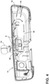
FIG. 2A , therear view assembly 10 is generally illustrated with thedisplay module 40, the electro-optic assembly 42, light guide, andbezel 44 removed from therear view assembly 10. Removal of these components exposes a radio frequency (RF)shield 46 and alower travel guide 48 forbuttons 50 of alower button assembly 51 that are disposed on thebottom wall 35 of thehousing 12, and thecircuit board assembly 16. Thecircuit board assembly 16 includes aprimary circuit board 52, which is disposed behind theRF shield 46 and asecondary circuit board 56 disposed above theRF shield 46. Theheatsink 54 includes a vertical portion disposed behind theprimary circuit board 52 and is positioned to draw heat from theprimary circuit board 52 during normal operation of theprimary circuit board 52. Theheatsink 54 also includes an upper horizontal portion that draws heat away from thesecondary circuit board 56 and which extends across a top portion of therear view assembly 10 below thetop wall 34 of thehousing 12. Thesecondary circuit board 56 is generally aligned in an orthogonal configuration relative to theprimary circuit board 52 for edge lit displays. However, it is also contemplated that the secondary (LED)circuit board 56 could be disposed directly behind thedisplay module 40. Consequently, thermal loading that is generated by theprimary circuit board 52 and thesecondary circuit board 56 may be concentrated near an upper portion of therear view assembly 10. As a result, theair mover 20 is configured to move air across the top portion of therear view assembly 10 to cool theheatsink 54,primary circuit board 52, andsecondary circuit board 56. - Referring now to
FIG. 2B , which illustrates theheatsink 54 after removal of theprimary circuit board 52 andRF shield 46, thesecondary circuit board 56 is shown adjacent the upper horizontal portion of theheatsink 54. Thelower travel guide 48 is also shown. Thelower travel guide 48 aids in aligning thebuttons 50 with switches on a bottom side of the primary circuit board 52 (FIG. 2A ). - With reference to
FIG. 2C , therear view assembly 10 is illustrated with theheatsink 54 removed including the electro-optic assembly 42 which shows the placement of theair mover 20 inside therear view assembly 10. In the illustrated embodiment, theair mover 20 is in the form of a blower configured to draw air into theinlet 22 defined in thebottom wall 35 of thehousing 12. The example shown inFIGS. 2B and2C shows theinlet 22 being defined by several apertures that extend through thebottom wall 35 of thehousing 12. However, theinlet 22 may take on a variety of configurations. Air is drawn into the blower through theinlet 22 and pushed toward thechannel 24 which is adjacent the primary andsecondary circuit boards heatsink 54. It will be understood that theair mover 20 may be any device configured to draw air or push air within a predefined space and is not limited to a blower. Also, it will be understood that theair mover 20 may be configured to move air throughout therear view assembly 10 in manners other than that specifically disclosed herein. As illustrated, theair mover 20 is substantially small and may include a relatively thin cross-section so that theair mover 20 takes up minimal space within thehousing 12. - With reference to
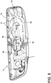
FIG. 3 , thebottom wall 35,top wall 34, first andsecond side walls rear wall 38 of thehousing 12 together define an inside surface of thehousing 12, within which the components of therear view assembly 10 reside. The inside surface includesside flanges 70 configured to provide some additional structural integrity to therear view assembly 10. In addition, the inside surface of thehousing 12 includes a plurality ofupper flanges 72 configured to help direct air that is being moved by theair mover 20. Theupper flanges 72 act in concert withbracket flanges 74 of asupport bracket 76 that is operably coupled with themount 14. Accordingly, theupper flanges 72 andbracket flanges 74 together define thechannel 24 through which ambient air is moved inside therear view assembly 10. - With reference now to
FIGS. 4-8 , once thesupport bracket 76 is removed,gaps 80 in thechannel 24 can be seen between theupper flanges 72 inside thehousing 12. As previously noted, when thesupport bracket 76 is positioned in thehousing 12, thesupport bracket 76, along with theupper flanges 72 of thehousing 12 define thechannel 24 through which air is moved across therear view assembly 10. Themount 14 extends into therear wall 38 of thehousing 12 at amount aperture 86. It will be understood that themount 14 may also be coupled to therear wall 38 of thehousing 12 or may take on another configuration. Air that is drawn in through theinlet 22 at thebottom wall 35 of thehousing 12 is pushed in the direction of arrows A across a top portion of theheatsink 54 andsecondary circuit board 56. As the air moves through thechannel 24 defined between theupper flanges 72,support bracket 76, and thetop wall 34 of thehousing 12, the air has the effect of cooling both theheatsink 54 and the primary andsecondary circuit boards housing 12 through theoutlet 30 as well as the gap between themount 14 and themount aperture 86. In another instance, thismount aperture 86 alone is used as theoutlet 30. As illustrated, theoutlet 30 includes a plurality ofvents 90 defined in therear wall 38 of thehousing 12 proximate themount aperture 86. Thevents 90 in the illustrated figures are defined through abulbous portion 92 of therear wall 38 of thehousing 12 proximate themount aperture 86. It will be understood that other configurations for theoutlet 30 are also contemplated. It will also be understood that the direction of air flow drawn in through theinlet 22 is not an airtight path. Rather, the direction of air flow has been specifically configured to pass through a variety of openings within thehousing 12 as set forth herein and illustrated inFIGS. 9-11 . - With reference now to
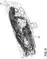
FIGS. 9-11 , several airflow models are shown where a backside of theheatsink 54 is illustrated withair lines 100 caused by the blower. Here, thehousing 12 and several other components have been removed so that the air lines of each airflow model shown inFIGS. 9-11 can be seen. As illustrated, air that is drawn in through the inlet 22 (FIG. 2C ) is blown mostly across a top portion of therear view assembly 10 through theflow channel 24. The air is then circulated on the backside of theheatsink 54 andprimary circuit board 52 until the warmed air leaves through theoutlet 30 proximate themount 14. As can be understood inFIG. 9 , theair lines 100 illustrated inside thehousing 12 circulate through various openings and slots defined within thehousing 12 such that thechannel 24 does not move all of the air but does move a substantial portion of it. This feature is by construction and is generally configured to allow air drawn in through theinlet 22 to cool specific areas of the printedcircuit board assembly 16 andheatsink 54 that may have higher thermal loading. The air, which has been warmed by theheatsink 54 as well as by the primary andsecondary circuit boards outlet 30 to the environment. - The tables shown in
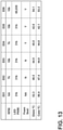
FIGS. 12 and13 illustrate the temperatures of the glass as simulated for the full display mirror 1.0, the full display mirror 2.0 without a blower, and the full display mirror 2.0 with a blower. As is readily understood for both the glass substrate 32 and the housing 12 (case), cooling occurs as a result of the addition of the blower, which is shown in the third column. Because the components inside therear view assembly 10, including the printedcircuit board assembly 16,heatsink 54, anddisplay module 40, operate at a cooler state with the blower, longevity of therear view assembly 10 and operability of the device is increased. The table ofFIG. 13 illustrates six experiments. In the first experiment (E01), the revolutions of theair mover 20 were not measured, but the LED pulse modulation was measured at 31,000. No foam seal was applied and the glass temperature was 52.3°C while thehousing 12 or case temperature was 56.4°C. Various features were modified in experiments E02-E06. Notably, as the revolutions per minute increase, the temperature of the glass substrate 32 and the housing 12 (case) tends to decrease. Moreover, application of the blower potentially accommodates a higher LED pulse with modulation, as shown in experiment E06. This table clearly illustrates that the additional blower has a positive impact on cooling the components within therear view assembly 10. - With reference now to
FIG. 14 , a full display mirror 1.0 without a blower is illustrated. The temperature of an upper portion of the glass substrate 32 is as high as 55.82°C.FIG. 15 illustrates a second generation full display mirror 2.0 without a blower which operates at 53.35°C. Operation of the full display mirror 2.0 is already cooler than operation of the full display mirror 1.0, however, when a blower is added to the full display mirror 2.0 (as shown inFIG. 16 ) the operating temperature of the glass substrate 32 is lowered even more, to 45.49°C. This is a significant cooling of the glass substrate 32 which allows for better functionality of the glass substrate 32 and components disposed within therear view assembly 10. The significant cooling also provides the option for faster processors, which generate even more heat, but which can be dealt with by the addition of theair mover 20. - With regard to
FIGS. 17-19 , the temperatures at thehousing 12 react similarly.FIG. 17 illustrates temperatures of thehousing 12 for the full display mirror 1.0. Various temperatures taken across thetop wall 34 of thehousing 12 range from 50.02°C to 50.95°C. The full display mirror 2.0 is warmer at thehousing 12 than the full display mirror 1.0 and includes temperatures of 56.69°C and 56.83°C taken at thetop wall 34 of thehousing 12. When a blower is added to the full display mirror 2.0, the temperature at thetop wall 34 of thehousing 12 is reduced to temperatures between 47.86°C and 39.29°C. Clearly, application of the blower to the full display mirror results in a cooler glass substrate 32 as well as acooler housing 12. - It will be understood by one having ordinary skill in the art that construction of the described disclosure and other components is not limited to any specific material. Other exemplary embodiments of the disclosure disclosed herein may be formed from a wide variety of materials, unless described otherwise herein.
- For purposes of this disclosure, the term "coupled" (in all of its forms, couple, coupling, coupled, etc.) generally means the joining of two components (electrical or mechanical) directly or indirectly to one another. Such joining may be stationary in nature or movable in nature. Such joining may be achieved with the two components (electrical or mechanical) and any additional intermediate members being integrally formed as a single unitary body with one another or with the two components. Such joining may be permanent in nature or may be removable or releasable in nature unless otherwise stated.
Claims (7)
- A rear view assembly (10) comprising:a housing (12) including a mount (14) extending therefrom;a circuit board assembly (16) disposed within the housing (12);an air mover (20) proximate a heatsink (54), the air mover (20) configured to draw ambient air from an inlet (22) into the housing (12),wherein the inlet (22) is disposed below the air mover (20) and adjacent to a lower button assembly (51);a channel (24) disposed within the housing (12), wherein the channel (24) is in fluid communication with the air mover (20) and configured to direct the air drawn into the housing (12) across a top portion of the heatsink (54); andan outlet (30) in fluid connection with the channel (24) and adjacent to the mount (14).
- The rear view assembly (10) of claim 1, further comprising:
a display device configured to display an image of an external scene of a vehicle. - The rear view assembly (10) of either one of claims 1-2, wherein the air mover (20) is coupled with the heatsink (54).
- The rear view assembly (10) of any one of claims 1-3, further comprising:
an electro-optic assembly (42) operable between generally clear and generally darkened states. - The rear view assembly (10) of any one of claims 1-4, wherein the channel (24) is at least partially defined by flanges (70, 72, 74) integrally formed with an inside surface of a rear wall (38) of the housing (12).
- The rear view assembly (10) of any one of claims 1-5, further comprising:
vents (90) that are in fluid communication with the channel (24), wherein the vents (90) are positioned proximate a mount aperture (86) defined through the housing (12). - The rear view assembly (10) of any one of claims 1-6, wherein the air mover (20) and the channel (24) are in fluid communication with the inlet (22) defined through a lower portion of the housing (12).
Applications Claiming Priority (2)
| Application Number | Priority Date | Filing Date | Title |
|---|---|---|---|
| US201862648784P | 2018-03-27 | 2018-03-27 | |
| PCT/IB2019/052465 WO2019186408A1 (en) | 2018-03-27 | 2019-03-26 | Full display mirror with integrated cooling system |
Publications (3)
| Publication Number | Publication Date |
|---|---|
| EP3776142A4 EP3776142A4 (en) | 2021-02-17 |
| EP3776142A1 EP3776142A1 (en) | 2021-02-17 |
| EP3776142B1 true EP3776142B1 (en) | 2022-01-19 |
Family
ID=68056086
Family Applications (1)
| Application Number | Title | Priority Date | Filing Date |
|---|---|---|---|
| EP19776633.0A Active EP3776142B1 (en) | 2018-03-27 | 2019-03-26 | Full display mirror with integrated cooling system |
Country Status (5)
| Country | Link |
|---|---|
| US (1) | US11353765B2 (en) |
| EP (1) | EP3776142B1 (en) |
| JP (1) | JP7112507B2 (en) |
| CN (1) | CN111918792B (en) |
| WO (1) | WO2019186408A1 (en) |
Families Citing this family (1)
| Publication number | Priority date | Publication date | Assignee | Title |
|---|---|---|---|---|
| WO2023014966A1 (en) * | 2021-08-06 | 2023-02-09 | Gentex Corporation | Heat mitigation for rearview assembly |
Family Cites Families (22)
| Publication number | Priority date | Publication date | Assignee | Title |
|---|---|---|---|---|
| DE2904825C3 (en) | 1979-02-08 | 1981-07-23 | Schuwerk, Fritz, 8000 München | Rearview mirrors for automobiles |
| AU667772B2 (en) | 1993-02-15 | 1996-04-04 | Fischerwerke Artur Fischer Gmbh & Co. Kg | Retaining device for spectacles, in particular for installation in motor vehicles |
| JPH09188195A (en) | 1996-01-09 | 1997-07-22 | Tokai Rika Co Ltd | Inner mirror |
| US5638895A (en) | 1996-03-25 | 1997-06-17 | Dodson; Douglas A. | Twin fan cooling device |
| US6201471B1 (en) | 1998-07-24 | 2001-03-13 | General Motors Corporation | Modular center stack console |
| WO2007053710A2 (en) * | 2005-11-01 | 2007-05-10 | Donnelly Corporation | Interior rearview mirror with display |
| US7031155B2 (en) | 2003-01-06 | 2006-04-18 | Intel Corporation | Electronic thermal management |
| KR100598943B1 (en) * | 2004-12-15 | 2006-07-12 | 주식회사 대우일렉트로닉스 | Rear view mirror with display panel |
| US7397461B1 (en) | 2005-03-17 | 2008-07-08 | Graham Jonathan W | Mirrored decorative video display concealment and cooling apparatus and method |
| JP4240095B2 (en) * | 2006-09-20 | 2009-03-18 | ソニー株式会社 | Sealed lamp device and projector |
| KR20090086398A (en) | 2006-10-04 | 2009-08-12 | 지멘스 악티엔게젤샤프트 외스터라이히 | Switched mode power supply |
| US20100080399A1 (en) | 2008-09-30 | 2010-04-01 | Visteon Global Technologies, Inc. | Method For Reducing Vehicle Noise |
| US8964278B2 (en) * | 2010-08-09 | 2015-02-24 | Gentex Corporation | Electro-optic system configured to reduce a perceived color change |
| US9435348B2 (en) | 2012-07-10 | 2016-09-06 | Asia Vital Components Co., Ltd. | Fan structure |
| CN202815955U (en) * | 2012-08-28 | 2013-03-20 | 广东铁将军防盗设备有限公司 | Automobile data recorder on rearview mirror |
| US9458979B2 (en) | 2012-12-14 | 2016-10-04 | Sl Corporation | Signal lamp for vehicle having a light guide and mirror housing and lamp housing with reflection unit and support unit |
| CN205044633U (en) * | 2015-09-06 | 2016-02-24 | 深圳市歌美迪电子技术发展有限公司 | Rearview mirror system of area heat dissipation function |
| US10189408B2 (en) * | 2015-11-02 | 2019-01-29 | Gentex Corporation | Display mirror assembly incorporating heatsink |
| CN205800936U (en) * | 2016-06-15 | 2016-12-14 | 房汉健 | A kind of novel rear view mirror |
| EP3507140B1 (en) | 2016-09-02 | 2020-10-28 | Gentex Corporation | Cooling device for rearview assembly |
| US10442360B2 (en) | 2017-03-02 | 2019-10-15 | Magna Mirrors Of America, Inc. | Interior rearview mirror assembly with display and tilt mechanism |
| US10642327B1 (en) * | 2017-08-14 | 2020-05-05 | Apple Inc. | Electronic devices with cooling systems |
-
2019
- 2019-03-26 CN CN201980022358.5A patent/CN111918792B/en active Active
- 2019-03-26 JP JP2020551819A patent/JP7112507B2/en active Active
- 2019-03-26 EP EP19776633.0A patent/EP3776142B1/en active Active
- 2019-03-26 WO PCT/IB2019/052465 patent/WO2019186408A1/en unknown
- 2019-03-26 US US16/365,039 patent/US11353765B2/en active Active
Also Published As
| Publication number | Publication date |
|---|---|
| US11353765B2 (en) | 2022-06-07 |
| EP3776142A4 (en) | 2021-02-17 |
| JP7112507B2 (en) | 2022-08-03 |
| US20190302563A1 (en) | 2019-10-03 |
| WO2019186408A1 (en) | 2019-10-03 |
| EP3776142A1 (en) | 2021-02-17 |
| CN111918792A (en) | 2020-11-10 |
| JP2021519238A (en) | 2021-08-10 |
| CN111918792B (en) | 2023-09-26 |
Similar Documents
| Publication | Publication Date | Title |
|---|---|---|
| EP3631571B1 (en) | Display apparatus and method of controlling the same | |
| US7068505B2 (en) | Air duct and electronic equipment using the air duct | |
| EP3280135B1 (en) | Display device | |
| EP3490354B1 (en) | Outdoor display apparatus having enhanced temperature stability | |
| CN105974662B (en) | Display device | |
| US7667968B2 (en) | Air-cooling system configuration for touch screen | |
| EP2797394B1 (en) | Digital signage | |
| US6043979A (en) | Heat-discharging LCD monitor | |
| US20160302331A1 (en) | System for Using Constricted Convection with Closed Loop Cooling System As the Convection Plate | |
| EP1968370A2 (en) | Cooling fan mounting structure for flat display, and plasma television set | |
| EP3938246B1 (en) | Rearview assembly with enhanced cooling | |
| EP1041431A3 (en) | Image projector with cooling means | |
| US10727155B2 (en) | Electronic apparatus for cooling heating element | |
| EP3776142B1 (en) | Full display mirror with integrated cooling system | |
| US5892654A (en) | Apparatus for improved air flow through a computer chassis | |
| US10114169B2 (en) | Display device | |
| JP2003279954A (en) | Liquid crystal display device | |
| US20060066761A1 (en) | Rear projection television | |
| JP2001177267A (en) | Electronic apparatus | |
| JP2001035397A (en) | Plasma display device | |
| JPH09284677A (en) | Display device | |
| CN113810528B (en) | Electronic equipment | |
| WO2022244494A1 (en) | Electronic instrument and imaging device | |
| JP2008096774A (en) | Display device | |
| JP2007067717A (en) | Imaging apparatus |
Legal Events
| Date | Code | Title | Description |
|---|---|---|---|
| STAA | Information on the status of an ep patent application or granted ep patent |
Free format text: STATUS: THE INTERNATIONAL PUBLICATION HAS BEEN MADE |
|
| PUAI | Public reference made under article 153(3) epc to a published international application that has entered the european phase |
Free format text: ORIGINAL CODE: 0009012 |
|
| STAA | Information on the status of an ep patent application or granted ep patent |
Free format text: STATUS: REQUEST FOR EXAMINATION WAS MADE |
|
| 17P | Request for examination filed |
Effective date: 20201027 |
|
| A4 | Supplementary search report drawn up and despatched |
Effective date: 20201202 |
|
| AK | Designated contracting states |
Kind code of ref document: A1 Designated state(s): AL AT BE BG CH CY CZ DE DK EE ES FI FR GB GR HR HU IE IS IT LI LT LU LV MC MK MT NL NO PL PT RO RS SE SI SK SM TR |
|
| AX | Request for extension of the european patent |
Extension state: BA ME |
|
| DAV | Request for validation of the european patent (deleted) | ||
| DAX | Request for extension of the european patent (deleted) | ||
| GRAP | Despatch of communication of intention to grant a patent |
Free format text: ORIGINAL CODE: EPIDOSNIGR1 |
|
| STAA | Information on the status of an ep patent application or granted ep patent |
Free format text: STATUS: GRANT OF PATENT IS INTENDED |
|
| RIC1 | Information provided on ipc code assigned before grant |
Ipc: G02F 1/153 20060101ALI20210908BHEP Ipc: B60R 1/12 20060101ALI20210908BHEP Ipc: G02F 1/1333 20060101ALI20210908BHEP Ipc: B60R 1/04 20060101ALI20210908BHEP Ipc: G06F 1/20 20060101AFI20210908BHEP |
|
| INTG | Intention to grant announced |
Effective date: 20211004 |
|
| GRAS | Grant fee paid |
Free format text: ORIGINAL CODE: EPIDOSNIGR3 |
|
| GRAA | (expected) grant |
Free format text: ORIGINAL CODE: 0009210 |
|
| STAA | Information on the status of an ep patent application or granted ep patent |
Free format text: STATUS: THE PATENT HAS BEEN GRANTED |
|
| AK | Designated contracting states |
Kind code of ref document: B1 Designated state(s): AL AT BE BG CH CY CZ DE DK EE ES FI FR GB GR HR HU IE IS IT LI LT LU LV MC MK MT NL NO PL PT RO RS SE SI SK SM TR |
|
| REG | Reference to a national code |
Ref country code: GB Ref legal event code: FG4D |
|
| REG | Reference to a national code |
Ref country code: CH Ref legal event code: EP |
|
| REG | Reference to a national code |
Ref country code: DE Ref legal event code: R096 Ref document number: 602019011095 Country of ref document: DE |
|
| REG | Reference to a national code |
Ref country code: AT Ref legal event code: REF Ref document number: 1464166 Country of ref document: AT Kind code of ref document: T Effective date: 20220215 |
|
| REG | Reference to a national code |
Ref country code: IE Ref legal event code: FG4D |
|
| REG | Reference to a national code |
Ref country code: LT Ref legal event code: MG9D |
|
| REG | Reference to a national code |
Ref country code: NL Ref legal event code: MP Effective date: 20220119 |
|
| REG | Reference to a national code |
Ref country code: AT Ref legal event code: MK05 Ref document number: 1464166 Country of ref document: AT Kind code of ref document: T Effective date: 20220119 |
|
| PG25 | Lapsed in a contracting state [announced via postgrant information from national office to epo] |
Ref country code: NL Free format text: LAPSE BECAUSE OF FAILURE TO SUBMIT A TRANSLATION OF THE DESCRIPTION OR TO PAY THE FEE WITHIN THE PRESCRIBED TIME-LIMIT Effective date: 20220119 |
|
| PG25 | Lapsed in a contracting state [announced via postgrant information from national office to epo] |
Ref country code: SE Free format text: LAPSE BECAUSE OF FAILURE TO SUBMIT A TRANSLATION OF THE DESCRIPTION OR TO PAY THE FEE WITHIN THE PRESCRIBED TIME-LIMIT Effective date: 20220119 Ref country code: RS Free format text: LAPSE BECAUSE OF FAILURE TO SUBMIT A TRANSLATION OF THE DESCRIPTION OR TO PAY THE FEE WITHIN THE PRESCRIBED TIME-LIMIT Effective date: 20220119 Ref country code: PT Free format text: LAPSE BECAUSE OF FAILURE TO SUBMIT A TRANSLATION OF THE DESCRIPTION OR TO PAY THE FEE WITHIN THE PRESCRIBED TIME-LIMIT Effective date: 20220519 Ref country code: NO Free format text: LAPSE BECAUSE OF FAILURE TO SUBMIT A TRANSLATION OF THE DESCRIPTION OR TO PAY THE FEE WITHIN THE PRESCRIBED TIME-LIMIT Effective date: 20220419 Ref country code: LT Free format text: LAPSE BECAUSE OF FAILURE TO SUBMIT A TRANSLATION OF THE DESCRIPTION OR TO PAY THE FEE WITHIN THE PRESCRIBED TIME-LIMIT Effective date: 20220119 Ref country code: HR Free format text: LAPSE BECAUSE OF FAILURE TO SUBMIT A TRANSLATION OF THE DESCRIPTION OR TO PAY THE FEE WITHIN THE PRESCRIBED TIME-LIMIT Effective date: 20220119 Ref country code: ES Free format text: LAPSE BECAUSE OF FAILURE TO SUBMIT A TRANSLATION OF THE DESCRIPTION OR TO PAY THE FEE WITHIN THE PRESCRIBED TIME-LIMIT Effective date: 20220119 Ref country code: BG Free format text: LAPSE BECAUSE OF FAILURE TO SUBMIT A TRANSLATION OF THE DESCRIPTION OR TO PAY THE FEE WITHIN THE PRESCRIBED TIME-LIMIT Effective date: 20220419 |
|
| PG25 | Lapsed in a contracting state [announced via postgrant information from national office to epo] |
Ref country code: PL Free format text: LAPSE BECAUSE OF FAILURE TO SUBMIT A TRANSLATION OF THE DESCRIPTION OR TO PAY THE FEE WITHIN THE PRESCRIBED TIME-LIMIT Effective date: 20220119 Ref country code: LV Free format text: LAPSE BECAUSE OF FAILURE TO SUBMIT A TRANSLATION OF THE DESCRIPTION OR TO PAY THE FEE WITHIN THE PRESCRIBED TIME-LIMIT Effective date: 20220119 Ref country code: GR Free format text: LAPSE BECAUSE OF FAILURE TO SUBMIT A TRANSLATION OF THE DESCRIPTION OR TO PAY THE FEE WITHIN THE PRESCRIBED TIME-LIMIT Effective date: 20220420 Ref country code: FI Free format text: LAPSE BECAUSE OF FAILURE TO SUBMIT A TRANSLATION OF THE DESCRIPTION OR TO PAY THE FEE WITHIN THE PRESCRIBED TIME-LIMIT Effective date: 20220119 Ref country code: AT Free format text: LAPSE BECAUSE OF FAILURE TO SUBMIT A TRANSLATION OF THE DESCRIPTION OR TO PAY THE FEE WITHIN THE PRESCRIBED TIME-LIMIT Effective date: 20220119 |
|
| PG25 | Lapsed in a contracting state [announced via postgrant information from national office to epo] |
Ref country code: IS Free format text: LAPSE BECAUSE OF FAILURE TO SUBMIT A TRANSLATION OF THE DESCRIPTION OR TO PAY THE FEE WITHIN THE PRESCRIBED TIME-LIMIT Effective date: 20220519 |
|
| REG | Reference to a national code |
Ref country code: DE Ref legal event code: R097 Ref document number: 602019011095 Country of ref document: DE |
|
| PG25 | Lapsed in a contracting state [announced via postgrant information from national office to epo] |
Ref country code: SM Free format text: LAPSE BECAUSE OF FAILURE TO SUBMIT A TRANSLATION OF THE DESCRIPTION OR TO PAY THE FEE WITHIN THE PRESCRIBED TIME-LIMIT Effective date: 20220119 Ref country code: SK Free format text: LAPSE BECAUSE OF FAILURE TO SUBMIT A TRANSLATION OF THE DESCRIPTION OR TO PAY THE FEE WITHIN THE PRESCRIBED TIME-LIMIT Effective date: 20220119 Ref country code: RO Free format text: LAPSE BECAUSE OF FAILURE TO SUBMIT A TRANSLATION OF THE DESCRIPTION OR TO PAY THE FEE WITHIN THE PRESCRIBED TIME-LIMIT Effective date: 20220119 Ref country code: MC Free format text: LAPSE BECAUSE OF FAILURE TO SUBMIT A TRANSLATION OF THE DESCRIPTION OR TO PAY THE FEE WITHIN THE PRESCRIBED TIME-LIMIT Effective date: 20220119 Ref country code: EE Free format text: LAPSE BECAUSE OF FAILURE TO SUBMIT A TRANSLATION OF THE DESCRIPTION OR TO PAY THE FEE WITHIN THE PRESCRIBED TIME-LIMIT Effective date: 20220119 Ref country code: DK Free format text: LAPSE BECAUSE OF FAILURE TO SUBMIT A TRANSLATION OF THE DESCRIPTION OR TO PAY THE FEE WITHIN THE PRESCRIBED TIME-LIMIT Effective date: 20220119 Ref country code: CZ Free format text: LAPSE BECAUSE OF FAILURE TO SUBMIT A TRANSLATION OF THE DESCRIPTION OR TO PAY THE FEE WITHIN THE PRESCRIBED TIME-LIMIT Effective date: 20220119 |
|
| REG | Reference to a national code |
Ref country code: CH Ref legal event code: PL |
|
| PLBE | No opposition filed within time limit |
Free format text: ORIGINAL CODE: 0009261 |
|
| STAA | Information on the status of an ep patent application or granted ep patent |
Free format text: STATUS: NO OPPOSITION FILED WITHIN TIME LIMIT |
|
| PG25 | Lapsed in a contracting state [announced via postgrant information from national office to epo] |
Ref country code: AL Free format text: LAPSE BECAUSE OF FAILURE TO SUBMIT A TRANSLATION OF THE DESCRIPTION OR TO PAY THE FEE WITHIN THE PRESCRIBED TIME-LIMIT Effective date: 20220119 |
|
| REG | Reference to a national code |
Ref country code: BE Ref legal event code: MM Effective date: 20220331 |
|
| 26N | No opposition filed |
Effective date: 20221020 |
|
| PG25 | Lapsed in a contracting state [announced via postgrant information from national office to epo] |
Ref country code: LU Free format text: LAPSE BECAUSE OF NON-PAYMENT OF DUE FEES Effective date: 20220326 Ref country code: LI Free format text: LAPSE BECAUSE OF NON-PAYMENT OF DUE FEES Effective date: 20220331 Ref country code: IE Free format text: LAPSE BECAUSE OF NON-PAYMENT OF DUE FEES Effective date: 20220326 Ref country code: CH Free format text: LAPSE BECAUSE OF NON-PAYMENT OF DUE FEES Effective date: 20220331 |
|
| PG25 | Lapsed in a contracting state [announced via postgrant information from national office to epo] |
Ref country code: SI Free format text: LAPSE BECAUSE OF FAILURE TO SUBMIT A TRANSLATION OF THE DESCRIPTION OR TO PAY THE FEE WITHIN THE PRESCRIBED TIME-LIMIT Effective date: 20220119 Ref country code: BE Free format text: LAPSE BECAUSE OF NON-PAYMENT OF DUE FEES Effective date: 20220331 |
|
| PGFP | Annual fee paid to national office [announced via postgrant information from national office to epo] |
Ref country code: FR Payment date: 20230222 Year of fee payment: 5 |
|
| PGFP | Annual fee paid to national office [announced via postgrant information from national office to epo] |
Ref country code: GB Payment date: 20230222 Year of fee payment: 5 Ref country code: DE Payment date: 20230221 Year of fee payment: 5 |
|
| P01 | Opt-out of the competence of the unified patent court (upc) registered |
Effective date: 20230503 |
|
| PG25 | Lapsed in a contracting state [announced via postgrant information from national office to epo] |
Ref country code: IT Free format text: LAPSE BECAUSE OF FAILURE TO SUBMIT A TRANSLATION OF THE DESCRIPTION OR TO PAY THE FEE WITHIN THE PRESCRIBED TIME-LIMIT Effective date: 20220119 |