EP3775985B1 - Verfahren und vorrichtungen zum abladen von ultraschalldaten - Google Patents
Verfahren und vorrichtungen zum abladen von ultraschalldaten Download PDFInfo
- Publication number
- EP3775985B1 EP3775985B1 EP19784407.9A EP19784407A EP3775985B1 EP 3775985 B1 EP3775985 B1 EP 3775985B1 EP 19784407 A EP19784407 A EP 19784407A EP 3775985 B1 EP3775985 B1 EP 3775985B1
- Authority
- EP
- European Patent Office
- Prior art keywords
- ultrasound
- multilines
- data
- addresses
- ultrasound device
- Prior art date
- Legal status (The legal status is an assumption and is not a legal conclusion. Google has not performed a legal analysis and makes no representation as to the accuracy of the status listed.)
- Active
Links
Images


Classifications
-
- G—PHYSICS
- G01—MEASURING; TESTING
- G01S—RADIO DIRECTION-FINDING; RADIO NAVIGATION; DETERMINING DISTANCE OR VELOCITY BY USE OF RADIO WAVES; LOCATING OR PRESENCE-DETECTING BY USE OF THE REFLECTION OR RERADIATION OF RADIO WAVES; ANALOGOUS ARRANGEMENTS USING OTHER WAVES
- G01S7/00—Details of systems according to groups G01S13/00, G01S15/00, G01S17/00
- G01S7/52—Details of systems according to groups G01S13/00, G01S15/00, G01S17/00 of systems according to group G01S15/00
- G01S7/52017—Details of systems according to groups G01S13/00, G01S15/00, G01S17/00 of systems according to group G01S15/00 particularly adapted to short-range imaging
- G01S7/52079—Constructional features
-
- A—HUMAN NECESSITIES
- A61—MEDICAL OR VETERINARY SCIENCE; HYGIENE
- A61B—DIAGNOSIS; SURGERY; IDENTIFICATION
- A61B8/00—Diagnosis using ultrasonic, sonic or infrasonic waves
- A61B8/42—Details of probe positioning or probe attachment to the patient
- A61B8/4209—Details of probe positioning or probe attachment to the patient by using holders, e.g. positioning frames
- A61B8/4236—Details of probe positioning or probe attachment to the patient by using holders, e.g. positioning frames characterised by adhesive patches
-
- A—HUMAN NECESSITIES
- A61—MEDICAL OR VETERINARY SCIENCE; HYGIENE
- A61B—DIAGNOSIS; SURGERY; IDENTIFICATION
- A61B8/00—Diagnosis using ultrasonic, sonic or infrasonic waves
- A61B8/44—Constructional features of the ultrasonic, sonic or infrasonic diagnostic device
- A61B8/4427—Device being portable or laptop-like
-
- A—HUMAN NECESSITIES
- A61—MEDICAL OR VETERINARY SCIENCE; HYGIENE
- A61B—DIAGNOSIS; SURGERY; IDENTIFICATION
- A61B8/00—Diagnosis using ultrasonic, sonic or infrasonic waves
- A61B8/44—Constructional features of the ultrasonic, sonic or infrasonic diagnostic device
- A61B8/4444—Constructional features of the ultrasonic, sonic or infrasonic diagnostic device related to the probe
- A61B8/4472—Wireless probes
-
- A—HUMAN NECESSITIES
- A61—MEDICAL OR VETERINARY SCIENCE; HYGIENE
- A61B—DIAGNOSIS; SURGERY; IDENTIFICATION
- A61B8/00—Diagnosis using ultrasonic, sonic or infrasonic waves
- A61B8/56—Details of data transmission or power supply
-
- G—PHYSICS
- G01—MEASURING; TESTING
- G01S—RADIO DIRECTION-FINDING; RADIO NAVIGATION; DETERMINING DISTANCE OR VELOCITY BY USE OF RADIO WAVES; LOCATING OR PRESENCE-DETECTING BY USE OF THE REFLECTION OR RERADIATION OF RADIO WAVES; ANALOGOUS ARRANGEMENTS USING OTHER WAVES
- G01S15/00—Systems using the reflection or reradiation of acoustic waves, e.g. sonar systems
- G01S15/88—Sonar systems specially adapted for specific applications
- G01S15/89—Sonar systems specially adapted for specific applications for mapping or imaging
- G01S15/8906—Short-range imaging systems; Acoustic microscope systems using pulse-echo techniques
- G01S15/8909—Short-range imaging systems; Acoustic microscope systems using pulse-echo techniques using a static transducer configuration
- G01S15/8915—Short-range imaging systems; Acoustic microscope systems using pulse-echo techniques using a static transducer configuration using a transducer array
-
- G—PHYSICS
- G01—MEASURING; TESTING
- G01S—RADIO DIRECTION-FINDING; RADIO NAVIGATION; DETERMINING DISTANCE OR VELOCITY BY USE OF RADIO WAVES; LOCATING OR PRESENCE-DETECTING BY USE OF THE REFLECTION OR RERADIATION OF RADIO WAVES; ANALOGOUS ARRANGEMENTS USING OTHER WAVES
- G01S7/00—Details of systems according to groups G01S13/00, G01S15/00, G01S17/00
- G01S7/52—Details of systems according to groups G01S13/00, G01S15/00, G01S17/00 of systems according to group G01S15/00
- G01S7/52017—Details of systems according to groups G01S13/00, G01S15/00, G01S17/00 of systems according to group G01S15/00 particularly adapted to short-range imaging
- G01S7/52023—Details of receivers
- G01S7/52034—Data rate converters
-
- G—PHYSICS
- G01—MEASURING; TESTING
- G01S—RADIO DIRECTION-FINDING; RADIO NAVIGATION; DETERMINING DISTANCE OR VELOCITY BY USE OF RADIO WAVES; LOCATING OR PRESENCE-DETECTING BY USE OF THE REFLECTION OR RERADIATION OF RADIO WAVES; ANALOGOUS ARRANGEMENTS USING OTHER WAVES
- G01S7/00—Details of systems according to groups G01S13/00, G01S15/00, G01S17/00
- G01S7/52—Details of systems according to groups G01S13/00, G01S15/00, G01S17/00 of systems according to group G01S15/00
- G01S7/52017—Details of systems according to groups G01S13/00, G01S15/00, G01S17/00 of systems according to group G01S15/00 particularly adapted to short-range imaging
- G01S7/52079—Constructional features
- G01S7/52084—Constructional features related to particular user interfaces
-
- G—PHYSICS
- G01—MEASURING; TESTING
- G01S—RADIO DIRECTION-FINDING; RADIO NAVIGATION; DETERMINING DISTANCE OR VELOCITY BY USE OF RADIO WAVES; LOCATING OR PRESENCE-DETECTING BY USE OF THE REFLECTION OR RERADIATION OF RADIO WAVES; ANALOGOUS ARRANGEMENTS USING OTHER WAVES
- G01S7/00—Details of systems according to groups G01S13/00, G01S15/00, G01S17/00
- G01S7/52—Details of systems according to groups G01S13/00, G01S15/00, G01S17/00 of systems according to group G01S15/00
- G01S7/52017—Details of systems according to groups G01S13/00, G01S15/00, G01S17/00 of systems according to group G01S15/00 particularly adapted to short-range imaging
- G01S7/52085—Details related to the ultrasound signal acquisition, e.g. scan sequences
- G01S7/52095—Details related to the ultrasound signal acquisition, e.g. scan sequences using multiline receive beamforming
-
- A—HUMAN NECESSITIES
- A61—MEDICAL OR VETERINARY SCIENCE; HYGIENE
- A61B—DIAGNOSIS; SURGERY; IDENTIFICATION
- A61B8/00—Diagnosis using ultrasonic, sonic or infrasonic waves
- A61B8/06—Measuring blood flow
-
- A—HUMAN NECESSITIES
- A61—MEDICAL OR VETERINARY SCIENCE; HYGIENE
- A61B—DIAGNOSIS; SURGERY; IDENTIFICATION
- A61B8/00—Diagnosis using ultrasonic, sonic or infrasonic waves
- A61B8/06—Measuring blood flow
- A61B8/065—Measuring blood flow to determine blood output from the heart
-
- A—HUMAN NECESSITIES
- A61—MEDICAL OR VETERINARY SCIENCE; HYGIENE
- A61B—DIAGNOSIS; SURGERY; IDENTIFICATION
- A61B8/00—Diagnosis using ultrasonic, sonic or infrasonic waves
- A61B8/08—Clinical applications
- A61B8/0833—Clinical applications involving detecting or locating foreign bodies or organic structures
- A61B8/085—Clinical applications involving detecting or locating foreign bodies or organic structures for locating body or organic structures, e.g. tumours, calculi, blood vessels, nodules
-
- A—HUMAN NECESSITIES
- A61—MEDICAL OR VETERINARY SCIENCE; HYGIENE
- A61B—DIAGNOSIS; SURGERY; IDENTIFICATION
- A61B8/00—Diagnosis using ultrasonic, sonic or infrasonic waves
- A61B8/08—Clinical applications
- A61B8/0883—Clinical applications for diagnosis of the heart
-
- A—HUMAN NECESSITIES
- A61—MEDICAL OR VETERINARY SCIENCE; HYGIENE
- A61B—DIAGNOSIS; SURGERY; IDENTIFICATION
- A61B8/00—Diagnosis using ultrasonic, sonic or infrasonic waves
- A61B8/08—Clinical applications
- A61B8/0891—Clinical applications for diagnosis of blood vessels
-
- A—HUMAN NECESSITIES
- A61—MEDICAL OR VETERINARY SCIENCE; HYGIENE
- A61B—DIAGNOSIS; SURGERY; IDENTIFICATION
- A61B8/00—Diagnosis using ultrasonic, sonic or infrasonic waves
- A61B8/48—Diagnostic techniques
- A61B8/485—Diagnostic techniques involving measuring strain or elastic properties
Definitions
- the aspects of the technology described herein relate to ultrasound devices. Some aspects relate to offloading of ultrasound data from ultrasound devices.
- Ultrasound devices may be used to perform diagnostic imaging and/or treatment, using sound waves with frequencies that are higher with respect to those audible to humans.
- Ultrasound imaging may be used to see internal soft tissue body structures, for example to find a source of disease or to exclude any pathology.
- pulses of ultrasound are transmitted into tissue (e.g., by using a probe)
- sound waves are reflected off the tissue, with different tissues reflecting varying degrees of sound.
- These reflected sound waves may then be recorded and displayed as an ultrasound image to the operator.
- the strength (amplitude) of the sound signal and the time it takes for the wave to travel through the body provide information used to produce the ultrasound image.
- Many different types of images can be formed using ultrasound devices, including real-time images. For example, images can be generated that show two-dimensional cross-sections of tissue, blood flow, motion of tissue over time, the location of blood, the presence of specific molecules, the stiffness of tissue, or the anatomy of a three-dimensional region.
- US 2006/293596 A1 discloses an ultrasonic diagnostic imaging system and method in which spatially compounded images are produced by transmitting ultrasound beams in different directions during a common transmit-receive interval. Echoes are received from the different beam directions and are beamformed by a multiline beamformer to produce differently steered beams of coherent echo signals. The echoes are combined on a spatial basis with echoes from different look directions which correspond to the same spatial location being combined. The resulting spatially compounded image is displayed.
- US 2006/241454 A1 discloses methods and systems in which transmit multibeams insonify an object with multiple noncollinear transmit beams fired substantially simultaneously.
- the noncollinear beams are along different scan lines of same scan geometry, or they belong to scan lines of different scan geometries.
- One or more receive beams are formed in parallel in response to each of the noncollinear beams.
- the scan geometry and/or center frequency is varied between the noncollinear transmit beams of a transmit event.
- US 2016/066893 A1 discloses a method for operating an ultrasound probe which is wirelessly connected to an ultrasound image providing apparatus via a communication channel.
- the ultrasound probe may reduce the number of scan lines constituting each of frames of the ultrasound image data.
- aspects of this disclosure relate to wearable ultrasound devices, such as methods for offloading ultrasound images from a wearable ultrasound device, circuit architectures for reducing the size of a wearable ultrasound device, various indications that may be monitored through ultrasound images offloaded from a wearable ultrasound device, and various therapies that a wearable ultrasound device may deliver.
- Imaging devices may include ultrasound transducers monolithically integrated onto a single semiconductor die to form a monolithic ultrasound device. Aspects of such ultrasound-on-a chip devices are described in U.S. Patent 10,856,840 titled “UNIVERSAL ULTRASOUND DEVICE AND RELATED APPARATUS AND METHODS,” filed on January 25, 2017 (and assigned to the assignee of the instant application).
- the reduced cost and increased portability of these new ultrasound devices may make them significantly more accessible to the general public than conventional ultrasound devices.
- the portability of these new ultrasound devices makes them suitable for incorporation into wearable devices, such as ultrasound patches, that can collect ultrasound data.
- Imaging a subject using an ultrasound patch that adheres to the subject, rather than using a conventional ultrasound probe, may be helpful for a number of reasons.
- An ultrasound patch may remain adhered to a patient and may therefore allow for easier continuous imaging and monitoring with ultrasound than monitoring with a probe, which requires another individual to constantly hold the probe on the patient. Continuous monitoring may be helpful in cases where real-time, continuous information from ultrasound imaging is required, as opposed to after-the-fact or periodic information.
- the ultrasound patch may be used for long-term imaging and monitoring with ultrasound.
- Long-term monitoring may refer to any period of time that is longer than a conventional ultrasound imaging session with a conventional ultrasound probe, and may be minutes, hours, days, weeks, months, or years, as examples. Long-term monitoring may be useful in cases where it is not known when a particular event (e.g., an adverse physiological event) may occur.
- the ultrasound patch may collect data from a subject outside of a medical setting, such as in the subject's home.
- the inventors have also recognized that it may be helpful for wearable ultrasound devices (such as ultrasound patches) to wirelessly offload to an auxiliary electronic device ultrasound data sufficient to construct an ultrasound image therefrom.
- Wireless offloading of ultrasound data from the ultrasound device may allow the ultrasound device to offload data while the patient wearing the ultrasound device performs routine activities. In other words, the patient wearing the ultrasound device need not be tethered, by a wired connection, to another auxiliary device to which the ultrasound device offloads data.
- offloading data sufficient to construct an ultrasound image therefrom may be helpful because an ultrasound image may provide more information than a transmitted alarm signal or metric, and because this may allow a medical professional to view the ultrasound image.
- ultrasound data may contain an unexpected indication that an ultrasound device may not be programmed to automatically detect.
- a medical professional may be able to detect the unexpected indication upon viewing the ultrasound image.
- a medical professional may need to monitor ultrasound images over an extended time period to confirm a diagnosis or other assessment of a patient. Offloading ultrasound images over an extended time period may facilitate this monitoring.
- a deep learning model may analyze ultrasound images to produce results (e.g., anatomical or physiological measurements).
- the ultrasound device may perform continuous and/or long-term monitoring of medical indications by wirelessly offloading ultrasound data sufficient to construct an ultrasound image therefrom.
- the data offload rate from the ultrasound device may be reduced by implementing compounding of multilines of ultrasound data on the ultrasound device that collects the ultrasound data, rather than on an auxiliary electronic device to which the ultrasound device offloads ultrasound data.
- the rate of data offloading from the ultrasound device may be reduced by a factor of p / N.
- N ⁇ 1, p ⁇ 1, and p ⁇ N.
- the inventors have further recognized that it may be helpful for the transducers of the ultrasound device to be arranged in a 1.75-dimensional (1.75d) array.
- groups of transducers in the elevation direction e.g., groups of transducers along a column in the transducer array
- Steering in the elevation direction may be helpful for an ultrasound patch because it may enable acquiring ultrasound images from different elevational planes without needing to detach the ultrasound patch from the position and orientation at which the ultrasound patch was adhered to the subject. For example, upon adhering the ultrasound patch to a subject's abdomen, it may be possible to use elevational steering to ensure that data is collected between the subject's ribs.
- the inventors have further recognized that it may be helpful for groups of transducers to share a transmit/receive circuit (e.g., a pulser and a receive amplifier), rather than each transducer having its own transmit/receive circuit, in order to reduce the size of the ultrasound device. Furthermore, the inventors have recognized that it may be helpful for the number of transducers in each group of transducers that share a transmit/receive circuit to be non-uniform. In particular, one group of transducers in a column sharing a transmit/receive circuit may have a different number of transducers than another group of transducers sharing a transmit/receive circuit.
- a transmit/receive circuit e.g., a pulser and a receive amplifier
- each group of transducers within a given column of the transducer array may contain fewer or an equal number of transducers compared with other groups of transducers located further towards the center of the column. This may be helpful because certain ultrasound beam profiles require that delays implemented at transducers located towards the ends of a column be larger delays than delays implemented at transducers located towards the center of a column. Therefore, it may be helpful to more tightly control delays at transducers located towards the ends of a column by grouping together smaller numbers of such transducers than with respect to transducers located towards the center of a column.
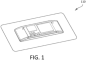
- a wearable ultrasound device may be embodied in an ultrasound patch that may be coupled to a patient.
- FIG. 1 illustrates an ultrasound patch 110
- FIG. 2 illustrates the ultrasound patch 110 coupled to a patient 112 ( FIG. 2 ) in accordance with certain embodiments described herein.
- the ultrasound patch 110 may be configured to offload, for example wirelessly, data collected by the ultrasound patch 110 to one or more external auxiliary devices (not shown) for further processing.
- a top housing of the ultrasound patch 110 is depicted in a transparent manner to depict exemplary locations of various internal components of the ultrasound patch.
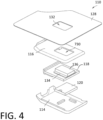
- FIGS. 3 and 4 show exploded views of the ultrasound patch 110 in accordance with certain embodiments described herein.
- the ultrasound patch 110 includes an upper housing 114, a lower housing 116, and a circuit board 118.
- the circuit board 118 may be configured to support various components, such as for example a heat sink 120, a battery 122, and communications circuitry 124.
- the communication circuitry 124 includes one or more short- or long-range communication platforms.
- Exemplary short-range communication platforms include Bluetooth (BT), Bluetooth Low Energy (BLE), and Near-Field Communication (NFC).
- Exemplary long-range communication platforms include WiFi and Cellular.
- the communication circuitry 124 may include front-end radio, antenna and other processing circuitry configured to communicate radio signal to an external auxiliary electronic device (not shown).
- the radio signal may include ultrasound imaging information obtained by the ultrasound patch 110.
- the communication platform transmits periodic beacon signals according to IEEE 802.11 and other prevailing standards.
- the beacon signal may include a BLE advertisement.
- an external auxiliary device (not shown) may respond to the ultrasound patch 110. That is, the response to the beacon signal may initiate a communication handshake between the ultrasound patch 110 and the auxiliary device.
- the auxiliary device may include a laptop computer, a desktop computer, a smartphone, a tablet device, or any other device configured for wireless communication.
- the auxiliary device may act as a gateway to cloud or internet communication.
- the auxiliary device may include the patient's own smart device (e.g., smartphone) which communicatively couples to the ultrasound patch 110 and periodically receives ultrasound information from the ultrasound patch 110. The auxiliary device may then communicate the received ultrasound information to external sources.
- the ultrasound patch 110 may offload ultrasound information to the auxiliary device in real-time.
- the circuit board 118 may include processing circuitry, including one or more controllers and/or field-programmable gate arrays (FPGAs) to direct communication through the communication circuitry 124.
- the circuit board 118 may engage the communication circuity 124 periodically or on as-needed basis to communicate information with one or more auxiliary devices.
- Ultrasound information may include signals and information defining an ultrasound image captured by the ultrasound patch 110.
- Ultrasound information may also include control parameters communicated from the auxiliary device to the ultrasound patch 110. The control parameters may dictate the scope of the ultrasound data/image to be obtained by ultrasound patch 110.
- the auxiliary device may store ultrasound information received from the ultrasound patch 110.
- the auxiliary device may relay ultrasound information received from the ultrasound patch 110 to another station.
- the auxiliary device may use WiFi to communicate the ultrasound information received from the ultrasound patch 110 to a cloud-based server.
- the cloud-based server may be a hospital server or a server accessible to the physician directing ultrasound imaging.
- the ultrasound patch 110 may send sufficient ultrasound information to the auxiliary device such that the auxiliary device may construct an ultrasound image therefrom. In this manner, communication bandwidth and power consumption may be minimized at the ultrasound patch 110.
- the auxiliary device may engage the ultrasound patch 110 through radio communication (i.e., through the communication circuitry 124) to actively direct operation of the ultrasound patch 110.
- the auxiliary device may direct the ultrasound patch 110 to produce ultrasound data from the patient at periodic intervals.
- the auxiliary device may direct the depth of the ultrasound images taken by the ultrasound patch 110.
- the auxiliary device may control the manner of operation of the ultrasound patch 110 so as to preserve power consumption at the battery 122.
- the auxiliary device may operate to cease imaging, increase imaging rate or communicate an alarm to the patient or to a third party (e.g., physician or emergency personnel).
- a plurality of through vias 126 may be used for a thermal connection between the heat sink 120 and one or more CMOS chips (not shown in FIG. 3 ).
- the CMOS chip may be an application-specific integrated circuit (ASIC).
- the ASIC may be part of an ultrasound-on-a-chip (i.e., a device including micromachined ultrasound transducers integrated with an ASIC or other semiconductor die containing integrated circuitry).
- the ultrasound patch 110 may also include a dressing 128 that provides an adhesive surface for both the ultrasound patch housing as well as to the skin of a patient.
- a dressing 128 is Tegaderm TM , a transparent medical dressing available from 3M Corporation.
- a lower housing 116 includes a generally rectangular shaped opening 130 that aligns with another opening 132 in the dressing 128.
- FIG. 4 another "bottom up" exploded view of the ultrasound patch 110 illustrates the location of ultrasonic transducers and integrated CMOS chip (generally indicated by 134) on the circuit board 118.
- An acoustic lens 136 mounted over the transducers/CMOS chip 134 is configured to protrude through openings 130 and 132 to make contact with the skin of a patient.
- the ultrasonic transducers may be arranged in a two-dimensional array. In some embodiments, the ultrasonic transducers may be arranged in a 1.75-dimensional array (as described further below).
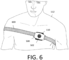
- the ultrasound patch 110 further includes a buckle 500 affixed to the upper housing 114 via a post 502 using, for example, a threaded engagement between the buckle 500 and the post 502. Other attachment configurations are also contemplated, however.
- the buckle 500 includes a pair of slots 504 that in turn accommodate a strap 600 ( FIG. 6 ).
- FIG. 6 shows an example of the ultrasound patch 110 fastened to the patient 112 using the strap 600 in accordance with certain embodiments described herein.
- the strap 600 is wrapped around the patient 112 and appropriately tightened in order to secure the ultrasound patch 110 to a desired location on the patient 112 for acquisition of desired ultrasound data and/or delivery of desired ultrasound energy.
- the ultrasound patch 110 may weigh no more than 4 lbs (e.g., no more than 2 lbs). In some embodiments, the volume of the wearable ultrasound device may be no greater than 250 cm 3 (e.g., no greater than 125 cm 3 , or no greater than 50 cm 3 ).
- the ultrasound transducers of the ultrasound patch 110 may be arranged in an array, and the height of the wearable ultrasound device along the direction orthogonal to the array of ultrasound transducers (i.e., orthogonal to the face of the array) may be no greater than 7 cm (e.g., no greater than 5 cm.) In some embodiments, the height of the wearable ultrasound device along the direction orthogonal to the array of ultrasound transducers may be no greater than a dimension of the array of ultrasound transducers (i.e., the length or width of the array).
- the portability/wearability (i.e., the acceptably small size/weight) of the ultrasound patch 110 may be due, in part, to monolithically integrating ultrasound transducers onto a single semiconductor die to form a monolithic ultrasound device.
- Aspects of such ultrasound-on-a chip devices are described in U.S. Patent 10,856,840 titled “UNIVERSAL ULTRASOUND DEVICE AND RELATED APPARATUS AND METHODS,” filed on January 25, 2017 (and assigned to the assignee of the instant application).
- CMOS chip 134 which may be an ultrasound-on-a-chip
- U.S. Patent 9,067,779 titled MICROFABRICATED ULTRASONIC TRANSDUCERS AND RELATED APPARATUS AND METHODS granted on June 30, 2015 (and assigned to the assignee of the present application).
- Additional information regarding the circuit components of the CMOS chip 134 may be found in U.S. Patent No. 9,521,991 titled "MONOLITHIC ULTRASONIC IMAGING DEVICES, SYSTEMS, AND METHODS," granted on December 20, 2016 (and assigned to the assignee of the instant application).
- an ultrasound device may wirelessly offload ultrasound data to an auxiliary device in real-time.
- the ultrasound information may include data sufficient to construct an ultrasound image therefrom.
- Wireless offloading of ultrasound data from the ultrasound device may allow the ultrasound device to offload data while the patient wearing the ultrasound device performs routine activities. In other words, the patient wearing the ultrasound device need not be tethered, by a wired connection, to another auxiliary device to which the ultrasound device offloads data.
- offloading data sufficient to construct an ultrasound image therefrom may be helpful because an ultrasound image may provide more information than a transmitted alarm signal or metric, and because this may allow a medical professional to view the ultrasound image.
- ultrasound data may contain an unexpected indication that an ultrasound device may not be programmed to automatically detect. By offloading data sufficient to construct a full ultrasound image, a medical professional may be able to detect the unexpected indication upon viewing the ultrasound image.
- the ultrasound device may produce 16 multilines of data per ultrasound transmit event, each multiline having 960 samples, and each sample having 16 bits.
- the ultrasound device may produce 72 multilines per frame and 10 frames per second.
- This data offload rate may exceed the data offloading capabilities of certain long-range communication platforms.
- the IEEE 802.11n wireless networking standard may support data offload rates up to 72 megabits/second and the IEEE 802.11g wireless networking standard may support data offload rates up to 54 megabits/second.
- the data offload rate from the ultrasound device may be reduced by implementing compounding of multilines of ultrasound data on the ultrasound device (e.g., on an FPGA in the ultrasound device, an ASIC in the ultrasound device, an ultrasound-on-a-chip in the ultrasound device, and/or other processing circuitry in the ultrasound device) that collects the ultrasound data, rather than on an auxiliary electronic device to which the ultrasound device offloads ultrasound data.
- the ultrasound probe may perform compounding of multilines rather than the host device.
- Multiple ultrasound transducers in the ultrasound device may transmit ultrasound waves into tissue during an ultrasound transmit event, and the ultrasound waves may be reflected off the tissue and detected by the ultrasound transducers in the ultrasound device.
- these detected reflection signals from multiple ultrasound transducers may be combined to form multilines (a.k.a. A-lines) in the direction of the transmitted beam.
- beamforming may be done first in an elevational direction and then in an azimuthal direction.
- certain of the ultrasound transducers may detect reflected ultrasound waves that are focused along the same direction as ultrasound waves collected following the previous ultrasound transmit event. In other words, multilines collected following different transmit events may overlap.
- incoherent compounding may include simple addition of overlapping multilines in linear or log domains
- coherent compounding may include addition of overlapping, weighted multilines with a phase shift.
- the offset in multilines between the first multiline of successive ultrasound transmit events may be referred to as the pitch factor.
- certain multilines may be collected following an ultrasound transmit event but not overlap with multilines collected following the subsequent ultrasound transmit event.
- certain multilines may be collected following an ultrasound transmit and overlap with multilines collected in the following ultrasound transmit.
- the pitch factor is 4, which means that for 16 multilines collected following each ultrasound transmit event, 12 multilines collected following one ultrasound transmit event may overlap with multilines collected following the successive ultrasound transmit event, while 4 multilines collected following the ultrasound transmit event will not overlap with multilines collected following the successive ultrasound transmit event.
- multilines collected "following" or “from” a transmit event should be understood to mean thatultrasound transducers may transmit ultrasound waves into tissue during a transmit event, and the ultrasound waves may be reflected off the tissue and detected by the ultrasound transducers. Using beamforming techniques, these reflection signals may be combined to form multilines.
- FIG. 7 shows an illustration of multilines from different ultrasound transmit events being focused in the same direction during ultrasound scanning.
- FIG. 7 shows a direction of scanning 700 and multilines 1 1 -16 1 , 1 2 -16 2 , 1 3 -16 3 , 1 4 -16 4 , and 1 5 -16 5 , wherein the multilines are drawn along their direction of focus.
- the main numeral in a multiline reference number represents the multiline's direction of focus in space relative to the other multilines collected from a particular ultrasound transmit event, with increasing numerals referring to multilines collected further along the direction of scanning 700.
- multilines a-b where b > a, should be understood to refer to a-b +1 multilines, where the b th multiline is focused furthest along the direction of scanning, the ( b -1) th multiline is focused next furthest along the direction of scanning, etc., and the a th multiline is focused least far along the direction of scanning.
- the superscript in a multiline reference number represents the transmit event from which the multilines are collected.
- FIG. 7 shows multilines from 5 ultrasound transmit events with 16 multilines per transmit.
- the pitch factor is 4, meaning that the first multiline of an ultrasound transmit event is offset by 4 multilines from the first multiline of the previous ultrasound transmit event.
- FIG. 7 shows a box around multilines from different ultrasound transmit events that are focused in the same direction.
- the multilines that are collected from an ultrasound transmit event, but do not overlap with multilines collected from the following ultrasound transmit event, are the multilines offloaded from the ultrasound device after the ultrasound transmit event.
- the remaining multilines collected from the ultrasound transmit event, which will overlap with multilines collected from the following ultrasound transmit event, are retained on the ultrasound device to be compounded with the overlapping multilines from the following ultrasound transmit event.
- IEEE 802.11 e.g., IEEE 802.11n and IEEE 802.11g
- the number of multilines per transmit may be between or equal to 2-32.
- the pitch factor may be between or equal to 1-8.
- Table 1 shows example values for these and other parameters that may be used for imaging different anatomical areas and structures: Table 1: Example values for various parameters that may be used for imaging different anatomical areas and structures.
- Anatomical Area/Structure Multilines/ Transmit Transmits/ Frame Pitch Factor Frames/ Second Abdominal 16 95 8 15-30 Abdominal Deep 16 87 2 15-30 Abdominal Vascular 16 72 4 15-20 Bladder 16 72 4 15-20 Cardiac 4 40 2 25-30 Cardiac Deep 4 40 2 20-30 Carotid 16 30 4 15-20 Obstetric 16 72 4 15-20
- the offload data rate from the ultrasound device may be reduced to any value between or equal to approximately 10 megabits/second - 1.73 gigaabits/second.
- the offload data rate may be in the range of 10 megabits/second - 32 megabits/second, 10 megabits/second - 54 megabits/second, 10-megabits/second - 72 megabits/second, 10-megabits/second - 100 megabits/second, 10-megabits/second - 450 megabits/second, 10-megabits/second - 866.7 megabits/second, or any suitable offload data rate.
- the offload data rate may depend on the anatomical area of structure being imaged.
- the offload data rate may depend on the values selected for certain imaging parameters such as those shown in Table 1, as well as on truncation as described further below.
- ultrasound images in which objects 5 mm apart can be spatially resolved may be offloaded.
- the ultrasound device may include a long-range communication platform employing a store and forward technique (e.g., a Bluetooth platform).
- the long-range communication platform may store data in memory on the ultrasound device, thus enabling the data to be offloaded later at a lower data rate.
- the techniques described herein may be used to reduce the amount of memory required on the ultrasound device.
- the amount of memory on the ultrasound device may be equal to or between approximately 5 kilobytes and 20 megabytes (e.g., between approximately 5 kilobytes and 100 kilobytes, between approximately 100 kilobytes and 1 megabyte, between approximately 1 megabyte and 10 megabytes, or between approximately 10 megabytes and 20 megabytes).
- the amount of memory on the ultrasound device may be greater than or less than these values.
- the amount of memory on the ultrasound device may be chosen based on the expected number of multilines per transmit event, samples per multiline, bits per sample, and acquisitions per frame, as well as the number of frames to be stored on the ultrasound device prior to offloading.
- the ultrasound device when offloading multilines, may truncate the digital multiline data. For example, if an analog-to-digital converter (ADC) in the ultrasound device converts analog multiline data to 16-bit digital multiline data, the ultrasound device may truncate the digital multiline data to 12 bits prior to offloading the multiline data. It should be appreciated that the ultrasound device may truncate the digital multiline data to other resolutions, such as 15 bits, 14 bits, 13 bits, 11 bits, or 10 bits.
- ADC analog-to-digital converter
- analog-to-digital converters with other resolutions, such as 18 bits or 20 bits, may be used in the ultrasound device, and the ultrasound device may truncate the digital multiline data to 19 bits, 18 bits, 17 bits, 16 bits, 15 bits, 14 bits, or 13 bits prior to offloading the multiline data.
- the number of bits to which the multiline data is truncated may depend on required image quality and/or signal-to-noise ratio in ultrasound images produced from the multiline data. Truncating the digital multiline data from M bits to N bits prior to offloading reduces the data offload rate by 1-N/M times the data offload rate without truncation.
- portions of the digital circuitry of the ultrasound device may include configurable bit depth.
- the bit depth of the digital output of an ADC on the ultrasound device may be configurable (i.e., the ADC may be configured to convert analog ultrasound data to any of a combination of 10 bits, 11 bits, 12 bits, 13 bits, 14 bits, 15 bits, 16 bits, 17 bits, 18 bits, 19 bits, or 20 bits, for example).
- portions of the digital computing pipeline and memory e.g., any of the memory buffers described below may be configured to operate on/store digital data having a configurable number of bits.
- Such portions of the digital computing pipeline may include, for example, digital filter circuitry, digital beamforming circuitry, digital quadrature demodulation (DQDM) circuitry, averaging circuitry, digital dechirp circuitry, digital time delay circuitry, digital phase shifter circuitry, digital summing circuitry, digital multiplying circuitry, and/or output buffering circuitry.
- Configurable bit depth may enable reduction in data rate in a similar manner as truncation of data.
- a user may select an option (e.g., a button or other selection means on the ultrasound device or an electronic device in communication with the ultrasound device) corresponding to the particular bit depth.
- Selection of that option may transmit signals to the computing pipeline in order to configure the computing pipeline to produce, operate on, and/or store digital having the particular number of bits.
- selection of a particular bit depth may be performed automatically by the ultrasound device or an electronic device in communication with the ultrasound device. For example, the ultrasound device or electronic device may determine the offload data rate possible from the ultrasound device and calculate the maximum bit depth possible given the available offload data rate.
- FIG. 8 shows an example process 800 for collecting ultrasound data in accordance with certain embodiments described herein.
- the process includes compounding multilines of ultrasound data on an ultrasound device configured to collect ultrasound data.
- the ultrasound device may be a wearable ultrasound device, such as an ultrasound patch (described in more detail with reference to FIGs. 1-6 ), and the process 800 may be performed by processing circuitry (e.g., a FPGA, an ASIC, and/or an ultrasound-on-a-chip) in the ultrasound device.
- the process 1000 begins at act 802.
- the ultrasound device collects N first multilines of ultrasound data following a first ultrasound transmit event.
- the process 800 then proceeds to act 804.
- the ultrasound device offloads p multilines of the first multilines.
- p may correspond to the pitch factor of multilines collected by the ultrasound device following successive ultrasound transmit events, and therefore the p multilines offloaded from the ultrasound device may be multilines that will not overlap with any multilines collected following subsequent ultrasound transmit events.
- the ultrasound device offloads the p multilines wirelessly.
- the ultrasound device may truncate the multiline data (e.g., to 10 or 12 bits) prior to offloading.
- the process 800 then proceeds to act 806.
- the ultrasound device collects N second multilines of ultrasound data following a second ultrasound transmit event that is subsequent to the first ultrasound transmit event.
- the process 800 then proceeds to act 808.
- the ultrasound device compounds N-p of the first multilines and N-p of the second multilines.
- the N-p of the first multilines and the N-p of the second multilines may be overlapping multilines.
- Compounding may include magnitude summation ("incoherent compounding") or complex summation ("coherent compounding") of overlapping multilines.
- incoherent compounding may include adding the N-p of the first multilines and the N-p of the second multilines in linear or log domains
- coherent compounding may include adding the N-p of the first multilines and the N-p of the second multilines with weighting and phase shifting applied.
- the process 800 then proceeds to act 810.
- the ultrasound device offloads p multilines that include p multilines of the first multilines compounded with p multilines of the second multilines.
- the p multilines offloaded from the ultrasound device may be multilines that will not overlap with any multilines collected following subsequent ultrasound transmit events.
- the ultrasound device may offload the p multilines wirelessly.
- the ultrasound device may truncate the multiline data (e.g., to 10 or 12 bits) prior to offloading.
- process 800 may proceed similarly for ultrasound transmit events that are not the first and second ultrasound transmit events in an imaging session.
- act 808 may include compounding N-p multilines from the current ultrasound transmit event with multilines collected from two or more previous ultrasound transmit events.
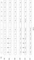
- FIG. 9 shows an example of collecting ultrasound data in accordance with certain embodiments described herein.
- the process illustrated in the example includes compounding multilines of ultrasound data on an ultrasound device configured to collect ultrasound data.
- the ultrasound device may be a wearable ultrasound device, such as an ultrasound patch (described in more detail with reference to FIGs. 1-6 ) that includes a memory buffer.
- FIG. 9 shows a symbolic illustration of the memory buffer (which may be part of volatile or non-volatile memory in the ultrasound device) storing data for multiple multilines at various addresses.
- the address indicator 901 indicates the addresses for the memory buffer.
- the data in the buffer is addressed with addresses 1-16.
- the buffer is configured to shift data out from the left side and shift data in from the right side (although it may be possible to the buffer to shift data out from the right side and shift data in from the left side).
- the data stored in the memory buffer is shown at different stages of the compounding process.
- multilines are represented with a main numeral and a subscript.
- the main numeral represents the relative position in space of the multilines collected from a particular ultrasound transmit event, with increasing numerals referring to multilines collected further along the scanning direction of the ultrasound imaging.
- Because ultrasound scanning may be considered to collect data in a polar coordinate system, in the following description, scanning will be referred to as proceeding from a negative angle direction to a positive angle direction.
- multiline 1 1 would be the multiline collected furthest in the negative angle direction and multiline 16 1 would be the multiline collected furthest in the positive angle direction.
- the superscript represents the transmit event in which the multilines are collected.
- the offset in multilines between the first multiline of successive ultrasound transmit event may be referred to as the pitch factor p.
- p of those N multilines will not overlap with multilines collected from the following ultrasound transmit event and N-p multilines will overlap with multilines collected from the following ultrasound transmit event.
- multilines 1 1 -4 1 i.e., the 4 multilines collected furthest in the negative angle direction
- multilines 5 1 -16 1 will overlap with multilines collected from the following ultrasound transmit event.
- the following ultrasound transmit event will result in 16 multilines 1 2 -16 2 being collected, with multilines 1 2 -12 2 overlapping with multilines 5 1 -16 1 .
- the ultrasound device updates the buffer to store data for the 16 multilines produced from the first transmit event, with multiline 1 1 stored at address 1, multiline 2 1 stored at address 2, etc.
- N 16 but other multilines per ultrasound transmit event values are possible.
- p corresponds to the pitch factor of the multilines, and therefore the p multilines 1 1 -4 1 offloaded from the ultrasound device are multilines that will not overlap with any multilines collected following subsequent ultrasound transmit events.
- the ultrasound device may offload the p multilines wirelessly.
- the ultrasound device may truncate the multiline data (e.g., to 10 or 12 bits) prior to offloading.
- p is 4, but other pitch factors (e.g., 2, 8) are possible.
- the ultrasound device compounds data from multilines 1 2 -12 2 from the second transmit event with the data at addresses 1-12 in the buffer, respectively (as represented by the addition symbol). Compounding may include magnitude summation ("incoherent compounding") or complex summation ("coherent compounding”) of overlapping multilines.
- incoherent compounding may include adding multilines 1 2 -12 2 from the second transmit event and the data at addresses 1-12 in the buffer in linear or log domains
- coherent compounding may include adding multilines 1 2 -12 2 from the second transmit event and the data at addresses 1-12 in the buffer with weighting and phase shifting applied.
- the ultrasound device may truncate the multiline data (e.g., to 10 or 12 bits) prior to offloading.
- the rightmost p addresses may be filled with zeros.
- the new multiline data collected at stage 908 may be compounded with the data in the rightmost p address (i.e., compounded with zeros), rather than overwriting the data in the rightmost p addresses. Accordingly, the new multiline data collected at stage 908 may be compounded with the data at all the addresses 1-16 of the memory buffer.
- FIG. 10 shows an example process 1000 for collecting ultrasound data in accordance with certain embodiments described herein.
- the process includes compounding multilines of ultrasound data on an ultrasound device configured to collect ultrasound data.
- the ultrasound device may be a wearable ultrasound device, such as an ultrasound patch (described in more detail with reference to FIGs. 1-6 ), and the process 1000 may be performed by processing circuitry (e.g., a FPGA, an ASIC, and/or an ultrasound-on-a-chip) in the ultrasound device.
- Process 1000 shows in flow chart form the process that is illustrated through the example in FIG. 9 for compounding multilines of ultrasound data on a memory buffer (which may be part of volatile or non-volatile memory) in an ultrasound device.
- the process 1000 begins at act 1002.
- the ultrasound device collects N multilines of ultrasound data following an ultrasound transmit event (referred to as the "present ultrasound transmit event"). The process 1000 then proceeds to act 1004.
- the ultrasound device updates data at addresses 1 to N-p of the memory buffer by compounding the data at addresses 1 to N-p of the memory buffer with multilines 1 to N-p of the N multilines.
- Compounding may include magnitude summation ("incoherent compounding") or complex summation ("coherent compounding") of overlapping multilines.
- incoherent compounding may include adding the data at addresses 1 to N-p of the memory buffer and multilines 1 to N-p of the N multilines in linear or log domains
- coherent compounding may include adding the data at addresses 1 to N-p of the memory buffer and multilines 1 to N-p of the N multilines with weighting and phase shifting applied.
- the memory buffer Prior to updating the data at addresses 1 to N-p of the memory buffer, the memory buffer may have stored, at addresses 1 to N-p, multilines of ultrasound data collected following one or more ultrasound transmit events prior to the ultrasound transmit event. If the ultrasound device collects multilines by scanning from a negative angle direction to a positive angle direction, the ultrasound device may compound the multiline furthest in the negative angle direction with the data at address 1, the multiline second furthest in the negative angle direction with the data at address 2, etc. As will be described further with reference to act 1010, each multiline collected following the present ultrasound transmit event may be compounded with the data in the memory buffer that, prior to the updating, stored multilines that overlap with the collected multiline. The process 1000 then proceeds to act 1006. In some embodiments, act 1006 may be performed prior to act 1004, or acts 1004 and 1006 may be performed simultaneously.
- the ultrasound device updates data at addresses N-p +1 to N of the memory buffer by overwriting the data at addresses N-p +1 to N of the memory buffer with multilines N-p +1 to N of the N multilines.
- addresses N-p+1 to N of the memory buffer may store data that is replicated elsewhere in the memory buffer, and can therefore be overwritten in act 1006 without loss of data.
- Acts 1002, 1004, and 1006 correspond to stage 908 in FIG. 9 .
- the process 1000 then proceeds to act 1008.
- the ultrasound device offloads the data at addresses 1 to p of the memory buffer from the ultrasound device, p may correspond to the pitch factor of multilines collected by the ultrasound device following successive ultrasound transmit events, and the p multilines offloaded from the ultrasound device may be multilines that will not overlap with any multilines collected following subsequent ultrasound transmit events.
- the ultrasound device may offload the p multilines wirelessly.
- the ultrasound device may truncate the multiline data (e.g., to 10 or 12 bits) prior to offloading. Act 1008 corresponds to stage 910. The process 1000 then proceeds to act 1010.
- the ultrasound device moves the data at the addresses p +1 to N of the memory buffer to the addresses 1 to N-p of the memory buffer. Therefore, the data that was previously at addresses 1 to p of the memory buffer, and was already offloaded from the ultrasound device, is removed from the memory buffer. Due to the pitch factor p , the data previously at address p +1 that is moved to address 1 corresponds to a multiline collected following the present ultrasound transmit event that will overlap with the multiline collected following the subsequent ultrasound transmit event that is furthest in the negative angle direction.
- the data previously at address p +2 that is moved to address 2 will correspond to a multiline collected from the present ultrasound transmit event that will overlap with the multiline collected from the subsequent ultrasound transmit event that is second furthest in the negative angle direction, etc.
- the ultrasound device may add the multiline furthest in the negative angle direction to the data at address 1, the multiline second furthest in the negative angle direction to the data at address 2, etc., (as described with reference to act 1004).
- each multiline collected following the subsequent ultrasound transmit event may be added to the data in the memory buffer that, prior to the adding, stored multilines that overlap with the multiline collected following the subsequent ultrasound transmit event (as described with reference to act 1004).
- the memory buffer may retain at addresses N-p + 1 to N the data that was stored at these addresses prior to act 1010. Accordingly, following act 1010, the data at addresses N-p+1 to N may be the same as the data at addresses N- 2 p +1 to N-p. Because the data at addresses N-p+1 to N may therefore be redundant, this data may be overwritten in act 1006 with loss of data. Act 1010 corresponds to stage 912. The process 1000 then proceeds to act 1012.
- the addresses N-p + 1 to N may be filled with zeros.
- new multiline data collected following the next ultrasound transmit event may be compounded with the data at addresses N-p+1 to N (i.e., compounded with zeros), rather than overwriting the data at addresses N-p+1 to N. Accordingly, the new multiline data collected following the next ultrasound transmit event may be compounded with the data at all N addresses of the memory buffer.
- the ultrasound device determines if there is another ultrasound transmit event to perform. If there is another ultrasound transmit event to perform, the process 1000 then proceeds to act 1002. If there is not another ultrasound transmit event to perform, the process 1000 then proceeds to act 1014.
- the ultrasound device offloads the data at addresses 1 to N of the memory buffer from the ultrasound device.
- This offloaded data may represent all the remaining multiline data that has not yet been offloaded.
- the ultrasound device may offload the p multilines wirelessly.
- the ultrasound device may truncate the multiline data (e.g., to 10 or 12 bits) prior to offloading. The process 1000 may then terminate.
- Process 1000 is a process for compounding multilines on an ultrasound device, and particularly a process for manipulating a memory buffer on the ultrasound device to perform this compounding.
- process 1000 because compounding of overlapping multilines occurs on the ultrasound device, only p multilines may be offloaded from the ultrasound device per transmit, rather than offloading N multilines, despite N (which is greater than p ) multilines being collected per ultrasound transmit event. This constitutes a reduction in data offload rate by a factor of p / N. The remaining N-p multilines that were collected following an ultrasound transmit event but not offloaded may be retained on the ultrasound device to be compounded with overlapping multilines collected from the following ultrasound transmit event.
- FIG. 11 shows an example of collecting ultrasound data in accordance with certain embodiments described herein.
- the example shown in FIG. 11 is a variant of the example shown in FIG. 9 .
- data in the memory buffer is shifted by p to the left.
- multilines 1- N produced from the new ultrasound transmit event may be used to update addresses 1- N , respectively, in the memory buffer.
- the multiline farthest in the negative scanning angle direction is used to update address 1 of the memory buffer
- the multiline second farthest in the negative scanning angle direction is used to update address 2 of the memory buffer, etc.
- no shifting occurs.
- multilines produced from a new ultrasound transmit event are used to update data in the memory buffer starting with the address directly after the rightmost address from which data was offloaded after the previous ultrasound transmit.
- the rightmost address from which data was offloaded after the previous ultrasound transmit is called m
- the multiline farthest in the negative scanning angle direction is used to update address m+1 of the memory buffer
- the multiline second farthest in the negative scanning angle direction is used to update address m +2 of the memory buffer, etc. If the ultrasound device reaches the end of the memory buffer, the remaining multilines are used to update addresses starting with address 1.
- multilines 1-8 may be used to update addresses 9-16 and multilines 9-16 may be used to update addresses 1-8. This may eliminate the shifting operation shown in FIG. 9 and increase efficiency of the compounding operation.
- FIG. 11 shows a symbolic illustration of the memory buffer (which may be part of volatile or non-volatile memory in the ultrasound device) storing data for multiple multilines at various addresses.
- the address indicator 1101 indicates the addresses for the memory buffer.
- the data in the buffer is addressed with addresses 1-16.
- the buffer is configured to shift data out from the left side and shift data in from the right side (although it may be possible to the buffer to shift data out from the right side and shift data in from the left side).
- the data stored in the memory buffer is shown at different stages of the compounding process.
- FIG. 11 uses the same naming scheme for multilines as in FIG. 9 .
- the ultrasound device updates the buffer to store data for the 16 multilines produced from the first transmit event, with multiline 1 1 stored at address 1, multiline 2 1 stored at address 2, etc.
- N 16 but other multilines per ultrasound transmit event values are possible.
- p corresponds to the pitch factor of the multilines, and therefore the p multilines 1 1 -4 1 offloaded from the ultrasound device are multilines that will not overlap with any multilines collected following subsequent ultrasound transmit events.
- the ultrasound device may offload the p multilines wirelessly.
- the ultrasound device may truncate the multiline data (e.g., to 10 or 12 bits) prior to offloading.
- p is 4, but other pitch factors (e.g., 2, 8) are possible.
- Compounding may include magnitude summation ("incoherent compounding") or complex summation (“coherent compounding”) of overlapping multilines.
- incoherent compounding may include adding the data from multilines 1 2 -12 2 from the second transmit event and the data at addresses 5-16 in the buffer in linear or log domains)
- coherent compounding may include adding the data from multilines 1 2 -12 2 from the second transmit event and the data at addresses 5-16 in the buffer with weighting and phase shifting applied.
- the ultrasound device overwrites the data that was offloaded in the stage 1104 (namely, multilines 1 1 -4 1 at addresses 1-4) with the multilines from the second transmit event that do not overlap with any multilines from the first transmit event (namely, multilines 13 2 -16 2 ).
- the ultrasound device compounds the first N-p multilines produced from the second transmit event with data at the first N-p addresses in the memory buffer after the rightmost address from which data was offloaded in stage 1104.
- the ultrasound device overwrites the data at the addresses from which data was offloaded in stage 1104 with the last p multilines produced from the second transmit event.
- the ultrasound device compounds the multilines produced from the second transmit event, from negative angle direction to positive angle direction, with the data at the remaining addresses after the rightmost address, and then compounds remaining multilines with the data starting at address 1. For example, if the rightmost address is 8, N-p is 12, and the number of addresses is 16, the ultrasound device may compound multilines 1-8 with the data at addresses 9-16, respectively, and compound multilines 9-12 with the data at addresses 1-4, respectively.
- the ultrasound device may truncate the multiline data (e.g., to 10 or 12 bits) prior to offloading.
- multilines 1 1 -16 1 collected at stage 1102 are added to addresses 1-16, respectively, it is also possible for the multilines to be added to the memory buffer starting at any address. For example, multilines 1 1 -15 1 may be added to addresses 2-16 and multiline 16 1 may be added to address 1.
- FIG. 12 shows an example process 1200 for collecting ultrasound data in accordance with certain embodiments described herein.
- the process includes compounding multilines of ultrasound data on an ultrasound device configured to collect ultrasound data.
- the ultrasound device may be a wearable ultrasound device, such as an ultrasound patch (described in more detail with reference to FIGs. 1-6 ), and the process 1200 may be performed by processing circuitry (e.g., a FPGA, an ASIC, and/or an ultrasound-on-a-chip) in the ultrasound device.
- Process 1200 shows in flow chart form the process that is illustrated through the example in FIG. 11 for compounding multilines of ultrasound data on a memory buffer (which may be part of volatile or non-volatile memory) in an ultrasound device.
- the process 1200 begins at act 1202.
- the ultrasound device initializes i to a default value.
- the default value may be 0.
- portions of the process 1200 may be iterated multiple times, and i may be a counter variable that is incremented after each iteration. The process 1200 then proceeds to act 1204.
- the ultrasound device collects N multilines of ultrasound data following an ultrasound transmit event (referred to as the "present ultrasound transmit event"). The process 1200 then proceeds to act 1206.
- the ultrasound device updates data at addresses (( p x i ) modulo N )+1 to (( p x i+N-p-1) modulo N )+1 of the memory buffer by compounding the data at addresses (( p x i ) modulo N )+1 to ((p x i+N-p-1 ) modulo N )+1 of the memory buffer with multilines 1 to N-p of the N multilines.
- p may correspond to the pitch factor of multilines collected by the ultrasound device following successive ultrasound transmit events.
- Compounding may include magnitude summation ("incoherent compounding") or complex summation ("coherent compounding”) of overlapping multilines.
- incoherent compounding may include adding the data at addresses (( p x i ) modulo N )+1 to (( p x i + N-p -1) modulo N )+1 of the memory buffer and multilines 1 to N-p of the N multilines in linear or log domains and coherent compounding may include adding the data at addresses (( p x i ) modulo N )+1 to (( p ⁇ i+N-p- 1) modulo N )+1 of the memory buffer and multilines 1 to N-p of the N multilines with weighting and phase shifting applied.
- the ultrasound device updates data at addresses (( p x i+N-p ) modulo N )+1 to (( p x i+N-1 ) modulo N )+1 of the memory buffer by overwriting the data at addresses (( p x i+N-p ) modulo N )+1 to (( p x i+N-1 ) modulo N )+ 1 of the memory buffer with multilines N-p +1 to N of the N multilines.
- multilines 13 2 -16 2 may overwrite the data at addresses 1-4, which previously contained multilines 1 1 -4 1 .
- the ultrasound device offloads the data at addresses (( p x i ) modulo N )+1 to (( p ⁇ i + p -1) modulo N )+1 of the memory buffer from the ultrasound device.
- the ultrasound device may offload the p multilines wirelessly. In some embodiments, the ultrasound device may truncate the multiline data (e.g., to 10 or 12 bits) prior to offloading. Act 1210 corresponds to stage 1108. The process 1200 then proceeds to act 1212.
- the ultrasound device determines if there is another ultrasound transmit event to perform. If there is another ultrasound transmit event to perform, the process 1200 then proceeds to act 1214. If there is not another ultrasound transmit event to perform, the process 1200 then proceeds to act 1216.
- the process 1200 then proceeds back to act 1204 to collect more multilines and update the memory buffer with the new multilines.
- the ultrasound device may ensure that multilines produced from a new ultrasound transmit event during the next iteration through the process 1200 will be used to update data in the memory buffer starting with the address directly after the rightmost address from which data was offloaded in act 1210 during the previous iteration through the process 1200. For example, following the example above, if the ultrasound device offloaded data at addresses 5-8 during one iteration through the process 1200, the ultrasound device may update data in the memory buffer starting with address 9 during the next iteration through the process 1200.
- the ultrasound device offloads the data at addresses 1 to N of the memory buffer from the ultrasound device.
- This offloaded data may represent all the remaining multiline data that has not yet been offloaded.
- the ultrasound device may offload the p multilines wirelessly.
- the ultrasound device may truncate the multiline data (e.g., to 10 or 12 bits) prior to offloading. The process 1200 may then terminate.
- the process 1200 may proceed using the addresses described above plus an offset.
- the ultrasound device may update data at addresses (( p ⁇ i ) modulo N )+1+ z to ((p x i+N-p-1) modulo N )+1+ z of the memory buffer by compounding the data at addresses (( p x i ) modulo N )+1+ z to ((p x i+N-p-1) modulo N )+1+ z of the memory buffer with multilines 1 to N-p of the N multilines, where z>0. All other addresses in the process 1200 may be similarly offset by the same z .
- the transducers of a wearable ultrasound device may be arranged in a 1.75-dimensional (1.75d) array.
- a 1.75d array groups of transducers in the elevation direction (e.g., groups of transducers along a column in the transducer array) can be independently controlled to allow for limited steering of ultrasound beams in the elevation direction.
- groups of transducers in the elevation direction may share a transmit/receive circuit (e.g., a pulser and a receive amplifier).
- a transmit/receive circuit e.g., a pulser and a receive amplifier.
- Steering in the elevation direction may be helpful for an ultrasound patch because it may enable acquiring ultrasound images from different elevational planes without needing to detach the ultrasound patch from the position and orientation at which the ultrasound patch was adhered to the subject. For example, upon adhering the ultrasound patch to a subject's abdomen, it may be possible to use elevational steering to ensure that data is collected between the subject's ribs.
- the inventors have further recognized that it may be helpful for groups of transducers to share a transmit/receive circuit (e.g., a pulser, a receive amplifier, and a switch), rather than each transducer having its own transmit/receive circuit, in order to reduce the size of the ultrasound device. Furthermore, the inventors have recognized that it may be helpful for the number of transducers in each group of transducers that share a transmit/receive circuit to be non-uniform. In particular, one group of transducers in a column sharing a transmit/receive circuit may have a different number of transducers than another group of transducers sharing a transmit/receive circuit.
- a transmit/receive circuit e.g., a pulser, a receive amplifier, and a switch
- each group in a column in the transducer array may contain fewer or an equal number of transducers compared with groups further towards the center of the column. This may be helpful because certain ultrasound beam profiles require that delays implemented at transducers towards the ends of a column be larger delays than delays implemented at transducers towards the center of a column. Therefore, it may be helpful to more tightly control delays at transducers towards the ends of a column by grouping together smaller numbers of transducers than transducers towards the center of a column.
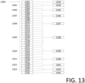
- FIG. 13 shows an example of electrically coupling groups of ultrasound transducers within a column 1300 of ultrasound transducers to transmit/receive circuits in accordance with certain embodiments described herein.
- the column 1300 may be along the elevational direction of an ultrasound transducer array.
- the column 1300 includes 32 ultrasound transducers 1301-1332, with the ultrasound transducer 1301 disposed at one end of the column 1300 and consecutively numbered ultrasound transducers disposed sequentially one after another until the ultrasound transducer 1332, which is disposed at the other end of the column 1300.
- FIG. 13 further shows 11 transmit/receive circuits 1333-1343.
- FIG. 15 shows an example of the circuitry included within each of the transmit/receive circuits 1333-1343.
- the ultrasound transducer 1301 is coupled to the transmit/receive circuit 1333.
- the ultrasound transducers 1302 and 1303 form a group 1345 of ultrasound transducers that are coupled to the transmit/receive circuit 1334.
- the ultrasound transducers 1304 and 1305 form a group 1346 of ultrasound transducers that are coupled to the transmit/receive circuit 1335.
- the ultrasound transducers 1306-1308 form a group 1347 of ultrasound transducers that are coupled to the transmit/receive circuit 1336.
- the ultrasound transducers 1309-1312 form a group 1348 of ultrasound transducers that are coupled to the transmit/receive circuit 1337.
- the ultrasound transducers 1313-1320 form a group 1349 of ultrasound transducers that are coupled to the transmit/receive circuit 1338.
- the ultrasound transducers 1321-1324 form a group 1350 of ultrasound transducers that are coupled to the transmit/receive circuit 1339.
- the ultrasound transducers 1325-1327 form a group 1351 of ultrasound transducers that are coupled to the transmit/receive circuit 1340.
- the ultrasound transducers 1328 and 1329 form a group 1352 of ultrasound transducers that are coupled to the transmit/receive circuit 1341.
- the ultrasound transducers 1330 and 1331 form a group 1353 of ultrasound transducers that are coupled to the transmit/receive circuit 1342.
- the ultrasound transducer 1332 is coupled to the transmit/receive circuit 1343.
- each group of ultrasound transducers in the column 1300 that shares a single transmit/receive circuit contains fewer or an equal number of transducers compared with groups further towards the center of the column 1300.
- the group 1349 contains eight ultrasound transducers and is the centermost group of ultrasound transducers in the column 1300.
- the groups 1348 and 1350 each contain four ultrasound transducers which is fewer transducers than in the group 1349, which is further towards the center of the column 1300.
- the groups 1347 and 1351 each contain three ultrasound transducers which is fewer transducers than in the groups 1348-1350, which are further towards the center of the column 1300.
- the groups 1346 and 1352 each contain two ultrasound transducers which is fewer transducers than in the groups 1347-1351, which are further towards the center of the column 1300.
- the groups 1345 and 1353 each contain two ultrasound transducers which is fewer transducers than or an equal number of transducers as in the groups 1346-1352, which are further towards the center of the column 1300.
- the ultrasound transducers 1301 and 1332 are each connected to a transmit/receive circuit that is coupled to only one ultrasound transducer. According, the ultrasound transducers 1301 and 1332 may be considered to constitute groups of one ultrasound transducer, which is fewer transducers than in the groups 1345-1353, which are further towards the center of the column 1300. As is evident from FIG.
- the number of ultrasound transducers per group is symmetric about the center of the column 1300 (i.e., proceeding from one end of the column 1300 to the other end, the number of ultrasound transducers per group is 1, 2, 2, 3, 4, 8, 4, 3, 2, 2, 1).
- the number of ultrasound transducers per group may still be symmetric about the center of the column 1300, but there may be different numbers of ultrasound transducers in each group compared with the groups shown in FIG. 13 ).
- there may be a different number of groups of ultrasound transducers i.e., a different number of groups than 11, which is how many groups are shown in the example of FIG. 13 ).
- each group may have the same number of ultrasound transducers (e.g., two or eight ultrasound transducers in each group).
- transducers along the elevational direction may be arranged in a row.
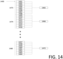
- FIG. 14 shows an example of electrically coupling groups of ultrasound transducers within a column 1400 of ultrasound transducers to transmit/receive circuits in accordance with certain embodiments described herein.
- the column 1400 may be along the elevational direction of an ultrasound transducer array.
- the column 1400 includes 64 ultrasound transducers 1401-1464 (not all of which are shown in FIG. 14 ), with the ultrasound transducer 1401 disposed at one end of the column 1400 and consecutively numbered ultrasound transducers disposed sequentially one after another until the ultrasound transducer 1464, which is disposed at the other end of the column 1400.
- FIG. 14 further illustrates 8 transmit/receive circuits 1465-1472 (not all of which are shown explicitly in FIG. 14 ).
- FIG. 15 shows an example of the circuitry included within each of the transmit/receive circuits 1465-1472.
- the ultrasound transducers 1401-1408 form a group 1473 of ultrasound transducers that are coupled to the transmit/receive circuit 1465.
- the ultrasound transducers 1409-1416 form a group 1474 of ultrasound transducers that are coupled to the transmit/receive circuit 1466.
- the ultrasound transducers 1417-1424 form a group 1475 of ultrasound transducers that are coupled to the transmit/receive circuit 1467.
- the ultrasound transducers 1425-1432 form a group 1476 of ultrasound transducers that are coupled to the transmit/receive circuit 1468.
- the ultrasound transducers 1433-1440 form a group 1477 of ultrasound transducers that are coupled to the transmit/receive circuit 1469.
- the ultrasound transducers 1441-1448 form a group 1478 of ultrasound transducers that are coupled to the transmit/receive circuit 1470.
- the ultrasound transducers 1449-1456 form a group 1479 of ultrasound transducers that are coupled to the transmit/receive circuit 1471.
- the ultrasound transducers 1457-1464 form a group 1480 of ultrasound transducers that are coupled to the transmit/receive circuit 1472.
- each group of ultrasound transducers in the column 1400 contains the same number of transducers. In the example of FIG. 14 , this number is 8, but other numbers of transducers per group are possible (e.g., 1, 2, 4, etc.).
- a column 1400 having an equal number of ultrasound transducers per group may be helpful for forming three-dimensional ultrasound images, for example.
- FIGs. 13 and 14 refers to transducers along the elevational direction being arranged in a column, in some embodiments transducers along the elevational direction may be arranged in a row. It should also be noted that in some embodiments, it may be possible to switch any of the transducers in FIGs. 13 and 14 on or off, and it may be possible to switch the polarity of any of the transducers in FIGs. 13 and 14 . For further description of switches that may be used in combination with the transducers may be found in U.S. Patent 10,175,347 titled "ULTRASOUND RECEIVER CIRCUITRY AND RELATED APPARATUS AND METHODS," filed on December 2, 2015 (and assigned to the assignee of the instant application).
- FIG. 15 shows example circuitry that may be included in one or more (e.g., each) of the transmit/receive circuits 1333-1343 and 1465-1472 in accordance with certain embodiments described herein.
- the circuitry includes a receive amplifier (e.g., a transimpedance amplifier) 1502, a pulser 1504, and a switch 1506.
- the receive amplifier 1502 includes an input 1512 and an output 1514.
- the pulser 1504 includes an input 1516 and an output 1518.
- the switch 1506 includes a first port 1520 and a second port 1522.
- the input 1512 of the receive amplifier 1502 is electrically coupled to the second port 1522 of the switch 1506.
- the output 1518 of the pulser 1504 is electrically coupled to the first port 1520 of the switch 1506.
- the switch 1506 When the switch 1506 is closed, the first port 1520 and the second port 1522 of the switch are electrically coupled together.
- the switch 1506 is open, the first port 1520 and the second port 15
- the output 1518 of the pulser 1504 and the first port 1520 of the switch 1506 may be electrically coupled to one or more of the ultrasound transducers (not shown in figure, e.g., any of the ultrasound transducers 1301-1332 and 1401-1464).
- the output 1514 of the receive amplifier 1502 may be coupled to a portion of an analog processing block, such as an averaging circuit.
- the input 1516 of the pulser may be electrically coupled to a waveform generating circuit (not shown in figure).
- the pulser 1504 may be configured to output (through the output 1518) a driving signal to one or more ultrasound transducers (e.g., any of the ultrasound transducers 1301-1332 and 1401-1464).
- the pulser 1504 may receive a waveform from a waveform generating circuit (not shown) and be configured to output a driving signal corresponding to the received waveform.
- the switch 1506 may be open such that the driving signal is not applied to the receive amplifier 1502.
- the ultrasound transducers may be configured to emit pulsed ultrasound signals into a structure, such as a patient, in response to the driving signal received from the pulser 1504.
- the pulsed ultrasonic signals may be back-scattered from structures in the body, such as blood cells or muscular tissue, to produce echoes that return to the ultrasound transducers.
- the ultrasound transducers may be configured to convert these echoes into electrical signals.
- the switch 1506 may be closed such that the ultrasound transducers may transmit the electrical signals representing the received echoes to the receive amplifier 1502.
- Imaging a subject using an ultrasound patch that adheres to the subject, rather than using a conventional ultrasound probe, may be helpful for a number of reasons.
- An ultrasound patch may remain adhered to a patient and may therefore allow for easier continuous imaging and monitoring with ultrasound than monitoring with a probe, which requires another individual to constantly hold the probe on the patient. Continuous monitoring may be helpful in cases where real-time, continuous information from ultrasound imaging is required, as opposed to after-the-fact or periodic information.
- the ultrasound patch may be used for long-term imaging and monitoring with ultrasound.
- Long-term monitoring may refer to any period of time that is longer than a conventional ultrasound imaging session with a conventional ultrasound probe, and may be minutes, hours, days, weeks, months, or years, as examples. Long-term monitoring may be useful in cases where it is not known when a particular event (e.g., an adverse physiological event) may occur.
- the ultrasound patch may collect data from a subject outside of a medical setting, such as in the subject's home. It should be appreciated that using the processes described with reference to FIGs. 8-12 , the ultrasound device may perform continuous and/or long-term monitoring of medical indications by wirelessly offloading ultrasound data sufficient to construct an ultrasound image therefrom.
- the ultrasound device may be configured to wirelessly offload ultrasound data sufficient to construct an ultrasound image containing information indicative of a medical indication. Offloading data sufficient to construct an ultrasound image may be helpful because an ultrasound image may provide more information than a transmitted alarm signal or metric, and because this allows a medical professional to view the ultrasound image.
- ultrasound data may contain an unexpected indication that a conventional device is not programmed to automatically detect. By offloading data sufficient to construct a full ultrasound image, a medical professional may be able to detect the unexpected indication upon viewing the ultrasound image. Additionally, automatic determination of conditions and metrics may be more prone to error than a medical professional performing the determination based on ultrasound images.
- An event may occur that may cause changes in a subject's body during a period of time following the event. Accordingly, after the event occurs, an ultrasound patch may be adhered to the subject for a period of time to monitor for those changes using ultrasound imaging.
- a subject may be monitored for healing after surgery, for a response to a drug after initiation of a drug delivery regimen, for adverse physiological events following an invasive procedure (e.g., after placement of a stent or for embedding a pacemaker), or for a response to cancer therapy.
- Types of cancer therapies to monitor may include brachytherapy, radiation therapy (e.g., x-rays, gamma rays, charged particles targeting cancer), chemotherapy, immunotherapy, targeted therapy (e.g., small-molecule drugs or monoclonal antibodies), hormone therapy, post-therapy recovery (e.g., after stem cell transplant), genetic-guided precision medicine (e.g., DNA sequencing, genomic testing, molecular profiling, or tumor profiling), and high intensity focused ultrasound therapy (HIFU); 2.
- radiation therapy e.g., x-rays, gamma rays, charged particles targeting cancer
- chemotherapy e.g., immunotherapy, targeted therapy (e.g., small-molecule drugs or monoclonal antibodies), hormone therapy, post-therapy recovery (e.g., after stem cell transplant), genetic-guided precision medicine (e.g., DNA sequencing, genomic testing, molecular profiling, or tumor profiling), and high intensity focused ultrasound therapy (HIFU); 2.
- HIFU high intensity focused ultrasound therapy
- an individual with cancer that is considered susceptible to metastasis may be monitored for metastasis
- fetal development may be monitored (e.g., by monitoring fetal heart, head, femur, or other organ size) in individuals with high risk pregnancies (e.g., history of miscarriage, or possible drug side effects in fetal development), or viability of a transplanted organ may be monitored.
- Other individuals who may be at risk for adverse events may include individuals with peripheral artery disease, diabetes, or those who have undergone heart bypass surgery; 3.
- Complications during surgery may be monitored in a patient by monitoring certain physiological parameters (e.g., cardiac function parameters) in real-time; 4.
- the location and/or trajectory of an instrument e.g., a needle, catheter, or stent
- an instrument e.g., a needle, catheter, or stent
- Certain physiological parameters e.g., left ventricular wall motion
- any indication for which conventional ultrasound imaging is used may be able to be monitored with an ultrasound patch.
- that indication may be monitored by adhering the ultrasound patch to the specific location on the subject with the specific orientation relative to the subject and configuring the ultrasound patch to acquire images using the specific imaging parameters.
- the ultrasound patch may further be configured to acquire images continuously or with a specific period, and left on the subject for a period of time (e.g., minutes, hours, days, weeks, months, or years).
- the ultrasound patch may be configured to wirelessly offload ultrasound data to an electronic device.
- the ultrasound patch may be configured to wirelessly offload the ultrasound data to an electronic device such as a smartphone, tablet, or laptop configured to generate ultrasound images from the ultrasound data and display the ultrasound images.
- the ultrasound patch may be configured to wirelessly offload the ultrasound data to one or remote servers (a.k.a., a "cloud" configuration).
- the one or more remote servers may be configured to generate ultrasound images from the ultrasound data and to transmit the ultrasound images to an electronic device such as a smartphone, tablet, or laptop configured to display the ultrasound images in real-time.
- the one or more remote servers may be configured to transmit the ultrasound images to an electronic device such as a smartphone, tablet, or laptop configured to generate ultrasound images from the ultrasound data and display the ultrasound images.
- the electronic device may be configured to generate the ultrasound images in real-time. This may be helpful, for example, for real-time monitoring for complications during surgery or for real-time monitoring of instrument placement.
- a medical professional may use the electronic device to access the ultrasound images not in real time.
- the ultrasound images may be downloaded to the electronic device, or transmitted to the electronic device in an email or text message, and the medical professional may access the ultrasound images at a time after the ultrasound data was collected.
- the medical professional may actively download ultrasound images from the one or more remote servers (e.g., by accessing a website) at a time after the ultrasound data was collected.
- real-time feedback is not critical
- monitoring a subject for healing after surgery for a response to a drug after initiation of a drug delivery regimen, for adverse physiological events following an invasive procedure, or for a response to cancer therapy.
- Additional examples in which real-time feedback is not critical include monitoring cancer for metastasis, fetal development, organ viability, and stress exercise. The medical professional may follow up with the subject with feedback after viewing the ultrasound images.
- the ultrasound patch may be configured to wirelessly offload ultrasound data sufficient to construct an ultrasound image containing information indicative of these indications.
- the ultrasound patch may be used to monitor tumor size and/or shape.
- tumor size/shape and ultrasound imaging see Fornage, Bruno D., Olivier Toubas, and Michel Morel, "Clinical, mammographic, and sonographic determination of preoperative breast cancer size," Cancer 60.4 (1987): 765-771 ; Ahuja, A. T., et al., "Ultrasound of malignant cervical lymph nodes," Cancer Imaging 8.1 (2008): 48 ; and Jalaguier-Coudray, A., and J. Thomassin-Piana, “Solid masses: what are the underlying histopathological lesions?” Diagnostic and interventional imaging 95.2 (2014): 153-168 .
- the ultrasound patch may be used to monitor tumor elasticity.
- tumor elasticity and ultrasound imaging see Garra, Brian S., “Tissue elasticity imaging using ultrasound,” Applied radiology 40.4 (2011): 24 and Grajo, Joseph R., and Richard G. Barr, “Compression elasticity imaging of the breast: an overview,” Applied Radiology 41.10 (2012): 18 .
- the ultrasound patch may be used to monitor tumor vascularity.
- tumor vascularity and ultrasound imaging see Park, Ah Young, et al., "An innovative ultrasound technique for evaluation of tumor vascularity in breast cancers: superb micro-vascular imaging," Journal of breast cancer 19.2 (2016): 210-213 ; Schroeder, Ralf-Juergen, et al., "Role of power Doppler techniques and ultrasound contrast enhancement in the differential diagnosis of focal breast lesions," European radiology 13.1 (2003): 68-79 ; and Gokhale, Sudheer, "Ultrasound characterization of breast masses," The Indian journal of radiology & imaging 19.3 (2009): 242 .
- the ultrasound patch may be used to monitor bladder fullness and/or volume, particularly in individuals with dysfunctional voiding.
- bladder fullness/volume and ultrasound imaging see van Karren, P. G., et al., "URIKA, continuous ultrasound monitoring for the detection of a full bladder in children with dysfunctional voiding: a feasibility study," Biomedical Physics & Engineering Express 3.1 (2017): 017005 and Dicuio, Mauro, et al., "Measurements of urinary bladder volume: comparison of five ultrasound calculation methods in volunteers," Arch Ital Urol Androl 77.1 (2005): 60-62 .
- the ultrasound patch may be used to monitor for bladder outlet obstruction.
- bladder outlet obstruction and ultrasound imaging see Arif, Bengal, et al., "Noninvasive Diagnosis of Bladder Outlet Obstruction in Patients with Lower Urinary Tract Symptoms Using Ultrasound Decorrelation Analysis," The Journal of urology 196.2 (2016): 490-497 ; Manieri, Carlo, et al., "The diagnosis of bladder outlet obstruction in men by ultrasound measurement of bladder wall thickness," The Journal of urology 159.3 (1998): 761-765 ; Han, Deok Hyun, et al., "The diagnostic efficacy of 3-dimensional ultrasound estimated bladder weight corrected for body surface area as an alternative nonurodynamic parameter of bladder outlet obstruction," The Journal of urology 185.3 (2011): 964-969 ; Kessler, Thomas M., et al., "Ultrasound assessment of detrusor thickness in men-can it predict bladder outlet obstruction and replace pressure flow study?” The Journal of urology 175.6 (2006): 21
- the ultrasound patch may be used to monitor pulse wave velocity and/or blood pressure.
- pulse wave velocity, blood pressure, and ultrasound imaging see Seo, Joohyun, et al., "Noninvasive arterial blood pressure waveform monitoring using two-element ultrasound system,” IEEE transactions on ultrasonics, ferroelectrics, and frequency control 62.4 (2015): 776-784 and Luo, Jianwen, Ronny X. Li, and Elisa E. Konofagou, "Pulse wave imaging of the human carotid artery: an in vivo feasibility study," IEEE transactions on ultrasonics, ferroelectrics, and frequency control 59.1 (2012): 132-181 .
- the ultrasound patch may be used to monitor inferior vena cava (IVC) diameter.
- IVC inferior vena cava
- the ultrasound patch may be used to monitor IVC volume.
- IVC volume and ultrasound imaging see Pershad, Jay, et al., "Bedside limited echocardiography by the emergency physician is accurate during evaluation of the critically ill patient.” Pediatrics 114.6 (2004): e667-e671 .
- the ultrasound patch may be used to monitor IVC collapsibility.
- IVC collapsibility may be calculated by measuring maximum IVC diameter (IVC max ) and minimum IVC diameter (IVC min ) and calculating IVC collapsibility as (IVC max - IVC min ) / IVC max x 100.
- IVC min may be measured at the end of inspiration and IVC max may be measured at the end of expiration.
- IVC collapsibility and ultrasound imaging see Brennan, J. Matthew, et al., "Handcarried ultrasound measurement of the inferior vena cava for assessment of intravascular volume status in the outpatient hemodialysis clinic," Clinical Journal of the American Society of Nephrology1.4 (2006): 749-753 .
- the ultrasound patch may be used to monitor IVC blood flow rate.
- IVC blood flow rate and ultrasound imaging see Indik, Julia H., Victor Chen, and Kathryn L. Reed, "Association of umbilical venous with inferior vena cava blood flow velocities," Obstetrics & Gynecology 77.4 (1991): 551-557 .
- the ultrasound patch may be used to monitor IVC wall motion.
- IVC wall motion and ultrasound imaging see Gullace, G., and M. T. Savoia, "Echocardiographic assessment of the inferior vena cava wall motion for studies of right heart dynamics and function," Clinical cardiology 7.7 (1984): 393-404 .
- monitoring diameter, volume, blood flow rate, and wall motion of the IVC using ultrasound imaging may also be relevant to monitoring diameter, volume, blood flow rate, and wall motion of other blood vessels.
- the ultrasound patch may be used to monitor intravascular volume.
- intravascular volume and ultrasound imaging see Brennan, J. Matthew, et al., "Handcarried ultrasound measurement of the inferior vena cava for assessment of intravascular volume status in the outpatient hemodialysis clinic.," Clinical Journal of the American Society of Nephrology1.4 (2006): 749-753 .
- the ultrasound patch may be used to monitor left ventricular wall motion.
- left ventricular wall motion and ultrasound imaging see Nakashiki, Kenichi, et al., "Usefulness of a novel ultrasound transducer for continuous monitoring treadmill exercise echocardiography to assess coronary artery disease," Circulation Journal 70.10 (2006): 1297-1302 .
- the ultrasound patch may be used to monitor cardiac output.
- cardiac output and ultrasound imaging see Haude, M., et al., "Continuous and Noninvasive Monitoring of Cardiac Output by Transesophageal Doppler Ultrasound," Transesophageal Echocardiography: A New Window to the Heart (1989): 260 .
- the ultrasound patch may be used to monitor ejection fraction.
- ejection fraction and ultrasound imaging see Qui ⁇ ones, Miguel A., et al., "A new, simplified and accurate method for determining ejection fraction with two-dimensional echocardiography," Circulation 64.4 (1981): 744-753 .
- the ultrasound patch may be used to monitor central venous pressure.
- central venous pressure and ultrasound imaging see Lipton, Bruce, "Estimation of central venous pressure by ultrasound of the internal jugular vein," The American journal of emergency medicine 18.4 (2000): 432-434 and Baumann, Ulrich A., et al., "Estimation of central venous pressure by ultrasound,” Resuscitation 64.2 (2005): 193-199 .
- the ultrasound patch may be used to monitor peripheral blood flow rate.
- peripheral blood flow and ultrasound imaging see Wladimiroff, J. W., H. M. Tonge, and P. A. Stewart, "Doppler ultrasound assessment of cerebral blood flow in the human fetus," BJOG: An International Journal of Obstetrics & Gynaecology 93.5 (1986): 471-475 ).
- the ultrasound patch may be used to monitor for abdominal aortic aneurysm.
- abdominal aortic aneurysm and ultrasound imaging see Wu, Stanley, et al. "Focus on: bedside ultrasound of the abdominal aorta.”
- the ultrasound patch may be used to monitor for deep vein thrombosis.
- deep vein thrombosis and ultrasound imaging see Lensing, Anthonie WA, et al., "Detection of deep-vein thrombosis by real-time B-mode ultrasonography," New England Journal of Medicine 320.6 (1989): 342-345 .
- the ultrasound patch may be used to monitor fetal heartbeat.
- fetal heartbeat and ultrasound imaging see Rakhmetova, Assel, Ultrasound Transducer Design for Continuous Fetal Heartbeat Monitoring, MS thesis, Hogskolen i S ⁇ r ⁇ st-Norge, 2016 .
- the ultrasound patch may be used to monitor for pregnancy.
- pregnancy and ultrasound imaging see Batzer, Frances R., et al., "Landmarks during the first forty-two days of gestation demonstrated by the ⁇ -subunit of human chorionic gonadotropin and ultrasound," American journal of obstetrics and gynecology 146.8 (1983): 973-979 .
- the ultrasound patch may be used to monitor follicle growth in ovaries.
- follicle growth in ovaries and ultrasound imaging see Queenan, John T., et al., "Ultrasound scanning of ovaries to detect ovulation in women," Fertility and sterility 34.2 (1980): 99-105 and Adams, J., et al., "Multifollicular ovaries: clinical and endocrine features and response to pulsatile gonadotropin releasing hormone," The Lancet 326.8469-8470 (1985): 1375-1379 .
- the ultrasound patch may be used to monitor for dehydration using ultrasound imaging of the IVC.
- ultrasound imaging For further description of dehydration and ultrasound imaging, see Modi, Payal, et al., "Accuracy of inferior vena cava ultrasound for predicting dehydration in children with acute diarrhea in resource-limited settings," PloS one 11.1 (2016): e0146859 and Chen, Lei, et al. "Use of bedside ultrasound to assess degree of dehydration in children with gastroenteritis.” Academic Emergency Medicine 17.10 (2010): 1042-1047 .
- the ultrasound patch may be used to monitor skin moisturization.
- skin moisturization see Mlosek, Robert K., et al., "The use of high frequency ultrasound imaging in skin moisturization measurement," Skin Research and Technology 19.2 (2013): 169-175 .
- the ultrasound patch may be used to monitor amniotic fluid volume.
- amniotic fluid volume For further description of amniotic fluid volume and ultrasound imaging, see Rutherford, Susan E., et al., "The four-quadrant assessment of amniotic fluid volume: an adjunct to antepartum fetal heart rate testing," Obstetrics & Gynecology 70.3 (1987): 353-356 ; Phelan, J. P., et al., "Amniotic fluid volume assessment with the four-quadrant technique at 36-42 weeks' gestation," The Journal of reproductive medicine 32.7 (1987): 540-542 ; Magann, E.
- the ultrasound patch may be used to monitor for pneumonia.
- pneumonia and ultrasound imaging see Wang, Guyi, et al. "Lung ultrasound: a promising tool to monitor ventilator-associated pneumonia in critically ill patients," Critical Care 20.1 (2016): 320 .
- the ultrasound patch may be used to monitor for pleural effusion.
- pleural effusion and ultrasound imaging see Prina, Maria, Antoni Torres, and Carlos Roberto Ribeiro Carvalho, "Lung ultrasound in the evaluation of pleural effusion.” Jornal Brasileiro de Pneumologia 40.1 (2014): 1-5 .
- the ultrasound patch may be used to monitor for pneumothorax.
- pneumothorax and ultrasound imaging see Husain, Lubna F., et al., "Sonographic diagnosis of pneumothorax," Journal of emergencies, trauma, and shock 5.1 (2012): 76 .
- the ultrasound patch may be used to monitor for chronic obstructive pulmonary disease (COPD).
- COPD chronic obstructive pulmonary disease
- the ultrasound patch may be used to monitor lung volume.
- lung volume For further description of lung volume and ultrasound imaging, see Pöhls, U. G., and A. Rempen, "Fetal lung volumetry by three-dimensional ultrasound,” Ultrasound in obstetrics & gynecology 11.1 (1998): 6-12 .
- the ultrasound patch may be used to monitor enteral feeding tube placement.
- enteral feeding tube placement and ultrasound imaging See Gubler, C., et al., "Bedside sonographic control for positioning enteral feeding tubes: a controlled study in intensive care unit patients," Endoscopy 38.12 (2006): 1256-1260 and Nedel, Wagner Luis, Mariana Nunes Ferreira Jost, and Jo ⁇ o Wilney Franco Filho, "A simple and fast ultrasonographic method of detecting enteral feeding tube placement in mechanically ventilated, critically ill patients," Journal of intensive care 5.1 (2017): 55 .
- the ultrasound patch may be used to monitor gastric emptying.
- gastric emptying and ultrasound imaging see Darwiche, Gassan, et al., "Measurement of gastric emptying by standardized real-time ultrasonography in healthy subjects and diabetic patients," Journal of Ultrasound in Medicine 18.10 (1999): 673-682 and Bateman, D. N., and T. A. Whittingham, "Measurement of gastric emptying by real-time ultrasound,” Gut 23.6 (1982): 524-527 .
- the ultrasound patch may be used to monitor for indigestion.
- EGG electrogastrography
- the EGG results may be correlated with the ultrasound imaging to enable detection and monitoring of indigestion using ultrasound imaging.
- indigestion and electrogastrography see Van der Voort, I. R., et al., "Electrogastrography as a diagnostic tool for delayed gastric emptying in functional dyspepsia and irritable bowel syndrome," Neurogastroenterology & Motility 15.5 (2003): 467-473 .
- the ultrasound patch may be used to monitor kidney function.
- kidney function and ultrasound imaging see Ikee, Ryota, et al., "Correlation between the resistive index by Doppler ultrasound and kidney function and histology," American Journal of Kidney Diseases 46.4 (2005): 603-609 and Petersen, L. J., et al. "The pulsatility index and the resistive index in renal arteries. Associations with long-term progression in chronic renal failure," Nephrology, dialysis, transplantation: official publication of the European Dialysis and Transplant Association-European Renal Association 12.7 (1997): 1376-1380 .
- the ultrasound patch may be used to monitor renal blood flow rate.
- renal blood flow rate and ultrasound imaging, see Wei, Kevin, et al., "Quantification of renal blood flow with contrast-enhanced ultrasound," Journal of the American College of Cardiology 37.4 (2001): 1135-1140s .
- the ultrasound patch may be used to monitor needle placement during pericardiocentesis.
- needle placement during pericardiocentesis and ultrasound imaging see Chandraratna, P. A. N., et al., "'Hands-Free' Continuous Transthoracic Monitoring of Pericardiocentesis Using a Novel Ultrasound Transducer," Echocardiography 20.6 (2003): 491-494 .
- the ultrasound patch may be used to monitor needle placement during amniocentesis.
- needle placement during amniocentesis and ultrasound imaging see Milunsky, Aubrey, and Jeff M. Milunsky, Genetic disorders and the fetus: diagnosis, prevention, and treatment, John Wiley & Sons, 2015 .
- the ultrasound patch may be used to monitor for vasospasm.
- vasospasm and ultrasound imaging see Lee, Benjamin, "Signal processing techniques for operator independent Doppler ultrasound: potential for use in transcranial Doppler ultrasound," MS Thesis, Ryerson University, 2011 ).
- the ultrasound patch may be used to monitor high-intensity focused ultrasound ablation.
- high-intensity focused ultrasound ablation and ultrasound imaging see Grondin, Julien, et al., "Real-time monitoring of high intensity focused ultrasound (HIFU) ablation of in vitro canine livers using harmonic motion imaging for focused ultrasound (HMIFU),” Journal of visualized experiments: JoVE 105 (2015 ).
- the ultrasound patch may be used to monitor drug delivery.
- the ultrasound patch may be used to monitor drug delivery.
- HIFU high-intensity focused ultrasound
- the ultrasound patch may be used to monitor hemodialysis access.
- hemodialysis access and ultrasound imaging see Finlay, David E., et al., "Duplex and Color Doppler Sonography of hemodialysis arteriovenous fistulas and grafts," Radiographics 13.5 (1993): 983-989 and Teodorescu, Victoria, Susan Gustavson, and Harry Schanzer, "Duplex ultrasound evaluation of hemodialysis access: a detailed protocol," International journal of nephrology 2012 (2012 ).
- the ultrasound patch may be used to monitor the vascular system, the liver, the gallbladder, the biliary system, the spleen, the pancreas, the gastrointestinal tract, the peritoneal cavity and abdominal wall, the urinary system, the retroperitoneum, the breast, the thyroid and parathyroid glands, the scrotum, the musculoskeletal system, the neonatal and pediatric abdomen, the neonatal and pediatric adrenal and urinary system, the neonatal and infant head, the infant and pediatric hip, the neonatal and infant spine, the thoracic cavity, the cerebrovascular system, the female pelvis, the uterus, the ovaries, the adnexa, obstetric measurements, gestational age, fetal growth, fetal congenital abnormalities, the placenta, the umbilical cord, amniotic fluid, fetal membranes, fetal hydrops, the fetal face and neck, the fetal neural axis, the fetal
- the ultrasound patch may also be used to emit ultrasonic energy for therapeutic purposes.
- ultrasonic energy may stimulate the baroreceptor reflex and help to reduce hypertension.
- the ultrasound patch may be adhered to a subject's carotid sinus, the location of the carotid receptors, and be configured to emit ultrasonic energy for a period of time (e.g., minutes, hours, days, months, years) in order to stimulate the carotid baroreceptors and help to reduce hypertensions.
- a period of time e.g., minutes, hours, days, months, years
- the ultrasound patch may be adhered adjacent to a subject's muscle and used to help heal the muscle by insonating the muscle with ultrasonic energy.
- muscle healing and ultrasound see Rantanen, Jussi, et al., "Effects of therapeutic ultrasound on the regeneration of skeletal myofibers after experimental muscle injury," The American journal of sports medicine 27.1 (1999): 54-59 ; Wilkin, L.
- the ultrasound patch may be adhered adjacent to a subject's tendon and used to help heal the tendon by insonating the tendon with ultrasonic energy.
- tendon healing and ultrasound see Enwemeka, Chukuka S. "The Effects of Therapeutic Ultrasound on Tendon Healing: A Biomechanical Study.” American journal of physical medicine & rehabilitation 68.6 (1989): 283-287 .
- the ultrasound patch may be adhered to a subject's skin and used to help heal the skin by insonating the skin with ultrasonic energy.
- ultrasonic energy For further description of skin healing and ultrasound, see Young, S. R., and M. Dyson. "Effect of therapeutic ultrasound on the healing of full-thickness excised skin lesions.” Ultrasonics 28.3 (1990): 175-180 .
- the ultrasound patch may be adhered adjacent to a subject's bone and used to help heal the bone (e.g., a bone fracture) by insonating the bone with ultrasonic energy.
- a subject's bone e.g., a bone fracture
- ultrasonic energy e.g., a ultrasonic energy
- the ultrasound patch may be used to deliver HIFU-based cancer treatment (e.g., for tumors of the brain, uterus, prostate, and soft tissue).
- HIFU-based cancer treatment e.g., for tumors of the brain, uterus, prostate, and soft tissue.
- the ultrasound patch may be used to deliver HIFU-based therapy that includes occlusion of blood vessels.
- the blood vessel occlusion may help, for example, in inducing hemostasis of internal bleeding, intervening in fetal blood sharing anomalies, and confining tumor blood supply.
- the ultrasound patch may be used to deliver HIFU-based therapy for augmentation of the body immune response.
- HIFU-based therapy for augmentation of the body immune response.
- HIFU-based therapy may be delivered in the low-thermal regime (i.e., approximately 47 degrees Celsius or less), high-thermal regime (i.e., above 47 degrees Celsius), low-mechanical regime (i.e., just under the cavitation limit), and/or the high-mechanical regime (i.e., just above the cavitation limit).
- low-thermal regime i.e., approximately 47 degrees Celsius or less
- high-thermal regime i.e., above 47 degrees Celsius
- low-mechanical regime i.e., just under the cavitation limit
- the high-mechanical regime i.e., just above the cavitation limit
- the ultrasound patch may be used to facilitate drug delivery.
- Mitragotri, Samir, Daniel Blankschtein, and Robert Langer "Ultrasound-mediated transdermal protein delivery," Science 269 (1995): 850-853 ; Mitragotri, Samir, and Joseph Kost, "Transdermal delivery of heparin and low-molecular weight heparin using low-frequency ultrasound," Pharmaceutical research 18.8 (2001): 1151-1156 ; Tachibana, Katsuro, “Transdermal delivery of insulin to alloxan-diabetic rabbits by ultrasound exposure," Pharmaceutical research 9.7 (1992): 952-954 ; Mitragotri, Samir, and Joseph Kost, “Low-Frequency Sonophoresis: A Noninvasive Method of Drug Delivery and Diagnostics," Biotechnology progress 16.3 (2000): 488-492 .
- a method comprising wirelessly offloading, from a wearable ultrasound device, ultrasound data sufficient for forming one or more ultrasound images therefrom.
- the wearable ultrasound device comprises an ultrasound patch in some embodiments.
- the wearable ultrasound device weighs no more than 4 lbs in some embodiments, and no more than 2 lbs in some embodiments.
- a volume of the wearable ultrasound device is no greater than 250 cm 3 in some embodiments, and no greater than 125 cm 3 in some embodiments, and no greater than 50 cm 3 in some embodiments.
- the wearable ultrasound device comprises a two-dimensional array of ultrasound transducers in some embodiments.
- the wearable ultrasound device comprises a 1.75-dimensional array of ultrasound transducers in some embodiments.
- the height of the wearable ultrasound device along a direction orthogonal to the array of ultrasound transducers is no greater than 7 cm in some embodiments.
- the height of the wearable ultrasound device along a direction orthogonal to the array of ultrasound transducers is no greater than 5 cm in some embodiments.
- the height of the wearable ultrasound device along a direction orthogonal to the array of ultrasound transducers is no greater than a dimension of the array of ultrasound transducers in some embodiments.
- Wirelessly offloading the ultrasound data comprises wirelessly offloading the ultrasound data at a data rate within a range of approximately 10 megabits/second-1.73 gigabits/second in some embodiments.
- Wirelessly offloading the ultrasound data comprises wirelessly offloading the ultrasound data at a data rate within a range of approximately 10-866.7 megabits/second in some embodiments.
- Wirelessly offloading the ultrasound data sufficient for forming the one or more ultrasound images therefrom comprises wirelessly offloading the ultrasound data at a data rate within a range of approximately 10-450 megabits/second in some embodiments.
- Wirelessly offloading the ultrasound data comprises wirelessly offloading the ultrasound data at a data rate within a range of approximately 10-100 megabits/second in some embodiments.
- Wirelessly offloading the ultrasound data comprises wirelessly offloading the ultrasound data at a data rate within a range of approximately 10-72 megabits/second in some embodiments.
- Wirelessly offloading the ultrasound data comprises wirelessly offloading the ultrasound data at a data rate within a range of approximately 10-54 megabits/second in some embodiments.
- Wirelessly offloading the ultrasound data comprises wirelessly offloading the ultrasound data at a data rate within a range of approximately 10-32 megabits/second.
- Wirelessly offloading the ultrasound data comprises wirelessly offloading the ultrasound data using a communication platform employing an IEEE 802.11 standard.
- the one or more ultrasound images include information indicative of a size or shape of a tumor in some embodiments.
- the one or more ultrasound images include information indicative of an elasticity of a tumor in some embodiments.
- the one or more ultrasound images include information indicative of a vascularity of a tumor in some embodiments.
- the one or more ultrasound images include information indicative of a fullness or a volume of a bladder in some embodiments.
- the one or more ultrasound images include information indicative of a bladder outlet obstruction in some embodiments.
- the one or more ultrasound images include information indicative of a pulse wave velocity or a blood pressure in some embodiments.
- the one or more ultrasound images include information indicative of a diameter of a blood vessel in some embodiments.
- the one or more ultrasound images include information indicative of a volume of a blood vessel in some embodiments.
- the one or more ultrasound images include information indicative of a collapsibility of a blood vessel in some embodiments.
- the one or more ultrasound images include information indicative of a blood flow rate through a blood vessel in some embodiments.
- the one or more ultrasound images include information indicative of a wall motion of a blood vessel in some embodiments.
- the blood vessel is an inferior vena cava in some embodiments.
- the one or more ultrasound images include information indicative of an intravascular volume in some embodiments.
- the one or more ultrasound images include information indicative of a left ventricular wall motion in some embodiments.
- the one or more ultrasound images include information indicative of a cardiac output in some embodiments.
- the one or more ultrasound images include information indicative of an ejection fraction in some embodiments.
- the one or more ultrasound images include information indicative of a central venous pressure in some embodiments.
- the one or more ultrasound images include information indicative of a peripheral blood flow rate in some embodiments.
- the one or more ultrasound images include information indicative of an abdominal aortic aneurysm in some embodiments.
- the one or more ultrasound images include information indicative of a deep vein thrombosis in some embodiments.
- the one or more ultrasound images include information indicative of a fetal heartbeat in some embodiments.
- the one or more ultrasound images include information indicative of a pregnancy in some embodiments.
- the one or more ultrasound images include information indicative of a follicle growth in ovaries in some embodiments.
- the one or more ultrasound images include information indicative of dehydration in some embodiments.
- the one or more ultrasound images include information indicative of a skin moisturization in some embodiments.
- the one or more ultrasound images include information indicative of an amniotic fluid volume in some embodiments.
- the one or more ultrasound images include information indicative of pneumonia in some embodiments.
- the one or more ultrasound images include information indicative of a pleural effusion in some embodiments.
- the one or more ultrasound images include information indicative of pneumothorax in some embodiments.
- the one or more ultrasound images include information indicative of chronic obstructive pulmonary disease (COPD) in some embodiments.
- COPD chronic obstructive pulmonary disease
- the one or more ultrasound images include information indicative of a lung volume in some embodiments.
- the one or more ultrasound images include information indicative of an enteral feeding tube placement in some embodiments.
- the one or more ultrasound images include information indicative of a gastric emptying in some embodiments.
- the one or more ultrasound images include information indicative of indigestion in some embodiments.
- the one or more ultrasound images include information indicative of a kidney function in some embodiments.
- the one or more ultrasound images include information indicative of a renal blood flow rate in some embodiments.
- the one or more ultrasound images include information indicative of a needle placement during pericardiocentesis in some embodiments.
- the one or more ultrasound images include information indicative of a needle placement during amniocentesis in some embodiments.
- the one or more ultrasound images include information indicative of a vasospasm in some embodiments.
- the one or more ultrasound images include information indicative of a high-intensity focused ultrasound ablation in some embodiments.
- the one or more ultrasound images include information indicative of a drug delivery in some embodiments.
- the one or more ultrasound images include information indicative of a hemodialysis access in some embodiments.
- a method comprising insonating, for a therapeutic purpose, by a wearable ultrasound device, a subject wearing the wearable ultrasound device.
- the wearable ultrasound device may be any of the types described above, of any of the weights and volumes described above.
- the wearable ultrasound device may comprise any of the arrays of ultrasound transducers described above and may have any of the heights described above.
- the subject wearing the wearable ultrasound device may comprise insonating any of a carotid baroreceptor of the subject, a muscle of the subject, a tendon of the subject, or a skin portion of the subject, a bone of the subject.
- the subject wearing the wearable ultrasound device comprises delivering high-intensity focused ultrasound (HIFU)-based cancer treatment in some embodiments.
- HIFU high-intensity focused ultrasound
- the subject wearing the wearable ultrasound device comprises delivering HIFU-based therapy that includes occlusion of a blood vessel in some embodiments.
- the subject wearing the wearable ultrasound device comprises delivering HIFU-based therapy for augmentation of a subject's immune response in some embodiments.
- the subject wearing the wearable ultrasound device comprises facilitating drug delivery in some embodiments.
- a method comprising compounding multilines of ultrasound data on an ultrasound device configured to collect the ultrasound data.
- compounding the multilines of the ultrasound data comprises: collecting, by the ultrasound device, N first multilines of the ultrasound data following a first ultrasound transmit event; collecting, by the ultrasound device, N second multilines of the ultrasound data following a second ultrasound transmit event that is subsequent to the first ultrasound transmit event; and compounding, on the ultrasound device, N-p of the first multilines and N-p of the second multilines, wherein p is a pitch factor of the first and second multilines of ultrasound data and is less than N .
- Compounding comprises incoherent compounding in some embodiments.
- Compounding comprises coherent compounding in some embodiments.
- the method further comprises offloading from the ultrasound device, following the first ultrasound transmit event, p multilines of the first multilines in some embodiments.
- the method further comprises truncating the p multilines of the first multilines to 12 bits prior to offloading in some embodiments.
- the method further comprises truncating the p multilines of the first multilines to 10 bits prior to offloading in some embodiments.
- Offloading the p multilines of the first multilines comprises wirelessly offloading the p multilines in some embodiments.
- Offloading the p multilines of the first multilines comprises wirelessly offloading the p multilines at a data rate within a range of approximately 10 megabits/second-1.73 gigabits/second in some embodiments. Offloading the p multilines of the first multilines comprises wirelessly offloading the p multilines at a data rate within a range of approximately 10-866.7 megabits/second in some embodiments. Offloading the p multilines of the first multilines comprises wirelessly offloading the p multilines at a data rate within a range of approximately 10-450 megabits/second in some embodiments.
- Offloading the p multilines of the first multilines comprises wirelessly offloading the p multilines at a data rate within a range of approximately 10-100 megabits/second in some embodiments. Offloading the p multilines of the first multilines comprises wirelessly offloading the p multilines at a data rate within a range of approximately 10-72 megabits/second in some embodiments. Offloading the p multilines of the first multilines comprises wirelessly offloading the p multilines at a data rate within a range of approximately 10-54 megabits/second in some embodiments. Offloading the p multilines of the first multilines comprises wirelessly offloading the p multilines at a data rate within a range of approximately 10-32 megabits/second in some embodiments. Offloading the p multilines of the first multilines comprises wirelessly offloading the p multilines using a communication platform employing an IEEE 802.11 standard in some embodiments.
- the p multilines of the first multilines do not overlap with any of the second multilines in some embodiments.
- the N-p multilines of the first multilines and the N-p multilines of the second multilines overlap in some embodiments.
- the method further comprises offloading from the ultrasound device, following the second ultrasound transmit event, p multilines of the first multilines compounded with p multilines of the second multilines in some embodiments.
- the method further comprises truncating the p multilines of the first multilines compounded with the p multilines of the second multilines to 12 bits prior to offloading, in some embodiments.
- the method further comprises truncating the p multilines of the first multilines compounded with the p multilines of the second multilines to 10 bits prior to offloading in some embodiments.
- Offloading the p multilines of the first multilines compounded with the p multilines of the second multilines comprises wirelessly offloading the p multilines in some embodiments.
- Wirelessly offloading the p multilines of the first multilines compounded with the p multilines of the second multilines comprises wirelessly offloading the p multilines at a data rate within a range of approximately 10 megabits/second-1.73 gigabits/second in some embodiments.
- Wirelessly offloading the p multilines of the first multilines compounded with the p multilines of the second multilines comprises wirelessly offloading the p multilines at a data rate within a range of approximately 10-866.7 megabits/second in some embodiments.
- Wirelessly offloading the p multilines of the first multilines compounded with the p multilines of the second multilines comprises wirelessly offloading the p multilines at a data rate within a range of approximately 10-450 megabits/second in some embodiments.
- Wirelessly offloading the p multilines of the first multilines compounded with the p multilines of the second multilines comprises wirelessly offloading the p multilines at a data rate within a range of approximately 10-100 megabits/second in some embodiments.
- Wirelessly offloading the p multilines of the first multilines compounded with the p multilines of the second multilines comprises wirelessly offloading the p multilines at a data rate within a range of approximately 10-72 megabits/second in some embodiments.
- Wirelessly offloading the p multilines of the first multilines compounded with the p multilines of the second multilines comprises wirelessly offloading the p multilines at a data rate within a range of approximately 10-54 megabits/second in some embodiments.
- Wirelessly offloading the p multilines of the first multilines compounded with the p multilines of the second multilines comprises wirelessly offloading the p multilines at a data rate within a range of approximately 10-32 megabits/second in some embodiments.
- Wirelessly offloading the p multilines of the first multilines compounded with the p multilines of the second multilines comprises wirelessly offloading the p multilines using a communication platform employing an IEEE 802.11 standard in some embodiments.
- N is between 2-32 and p is between 1-8 in some embodiments.
- the ultrasound device comprises digital circuitry having configurable bit depth in some embodiments.
- Compounding the multilines of the ultrasound data on the ultrasound device comprises compounding the multilines of the ultrasound data on a field-programmable gate array (FPGA) on the ultrasound device in some embodiments.
- FPGA field-programmable gate array
- Compounding the multilines of the ultrasound data on the ultrasound device comprises compounding the multilines of the ultrasound data on an application-specific integrated circuit (ASIC) on the ultrasound device in some embodiments.
- Compounding the multilines of the ultrasound data on the ultrasound device comprises compounding the multilines of the ultrasound data on an ultrasound-on-a-chip on the ultrasound device in some embodiments.
- the ultrasound device comprises a wearable ultrasound device in some embodiments.
- the ultrasound device may comprise an ultrasound patch of any of the weights and sizes described previously.
- the ultrasound device may include of the arrays of ultrasound transducers described previously, with any of the heights previously described.
- the ultrasound device comprises between approximately 5 kilobytes and 20 megabytes of memory in some embodiments.
- a method for collecting ultrasound data on an ultrasound device comprises: collecting N multilines of ultrasound data following an ultrasound transmit event; and updating data at addresses 1 to N of the memory buffer by: compounding data at addresses (( p x i ) modulo N )+1 to ((p x i + N-p -1) modulo N )+1 of the memory buffer with multilines 1 to N-p of the N multilines; and overwriting data at addresses (( p x i + N-p ) modulo N )+1 to ((p x i + N -1) modulo N )+1 of the memory buffer with multilines N-p +1 to N of the N multilines, wherein: p comprises a pitch factor of multilines collected by the ultrasound device following successive ultrasound transmit events; and i comprises a counter variable.
- Compounding comprises incoherent compounding in some embodiments.
- Compounding comprises coherent compounding in some embodiments.
- the method further comprises: prior to updating the data at the addresses 1 to N of the memory buffer, storing at the addresses 1 to N of the memory buffer multilines of ultrasound data collected following one or more ultrasound transmit events prior to the ultrasound transmit event in some embodiments.
- the method further comprises offloading data at addresses (( p x i) modulo N )+1 to ((p x i + p -1) modulo N )+1 of the memory buffer from the ultrasound device in some embodiments.
- the method further comprises truncating the data at addresses 1 to p of the memory buffer to 12 bits prior to offloading in some embodiments.
- the method further comprises truncating the data at addresses 1 to p of the memory buffer to 10 bits prior to offloading in some embodiments.
- Offloading the data at addresses 1 to p of the memory buffer comprises wirelessly offloading the data at addresses 1 to p of the memory buffer in some embodiments.
- Wirelessly offloading the data at addresses 1 to p of the memory buffer comprises wirelessly offloading the data at addresses 1 to p of the memory buffer at a data rate within a range of approximately 10 megabits/second-1.73 gigabits/second in some embodiments.
- Wirelessly offloading the data at addresses 1 to p of the memory buffer comprises wirelessly offloading the data at addresses 1 to p of the memory buffer at a data rate within a range of approximately 10-866.7 megabits/second in some embodiments.
- Wirelessly offloading the data at addresses 1 to p of the memory buffer comprises wirelessly offloading the data at addresses 1 to p of the memory buffer at a data rate within a range of approximately 10-450 megabits/second in some embodiments.
- Wirelessly offloading the data at addresses 1 to p of the memory buffer comprises wirelessly offloading the data at addresses 1 to p of the memory buffer at a data rate within a range of approximately 10-100 megabits/second in some embodiments.
- Wirelessly offloading the data at addresses 1 to p of the memory buffer comprises wirelessly offloading the data at addresses 1 to p of the memory buffer at a data rate within a range of approximately 10-72 megabits/second in some embodiments.
- Wirelessly offloading the data at addresses 1 to p of the memory buffer comprises wirelessly offloading the data at addresses 1 to p of the memory buffer at a data rate within a range of approximately 10-54 megabits/second in some embodiments.
- Wirelessly offloading the data at addresses 1 to p of the memory buffer comprises wirelessly offloading the data at addresses 1 to p of the memory buffer at a data rate within a range of approximately 10-32 megabits/second in some embodiments.
- Wirelessly offloading the data at addresses 1 to p of the memory buffer comprises wirelessly offloading the data at addresses 1 to p of the memory buffer using a communication platform employing an IEEE 802.11 standard in some embodiments.
- the method further comprises incrementing i by 1 after offloading the data at addresses 1 to p of the memory buffer in some embodiments.
- N is between 2-32 and p is between 1-8 in some embodiments.
- the ultrasound device comprises digital circuitry having configurable bit depth in some embodiments.
- the ultrasound device may be a wearable ultrasound patch, and may have any of the weights or sizes previously described, including any of the volumes and heights previously described.
- the ultrasound device may comprise an array of any of the types previously described, with any of the heights previously described.
- the ultrasound device comprises between approximately 5 kilobytes and 20 megabytes of memory in some embodiments.
- a method for collecting ultrasound data on an ultrasound device comprises collecting N multilines of ultrasound data following an ultrasound transmit event; and updating data at addresses 1 to N of the memory buffer by: compounding data at addresses 1 to N-p of the memory buffer with multilines 1 to N-p of the N multilines; and overwriting data at addresses N-p +1 to N of the memory buffer with multilines N-p +1 to N of the N multilines, wherein p comprises a pitch factor of multilines collected by the ultrasound device following successive ultrasound transmit events.
- Compounding comprises incoherent compounding in some embodiments.
- Compounding comprises coherent compounding in some embodiments.
- the method further comprises prior to updating the data at the addresses 1 to N of the memory buffer, storing at the addresses 1 to N of the memory buffer multilines of ultrasound data collected following one or more ultrasound transmit events prior to the ultrasound transmit event in some embodiments.
- the method further comprises offloading the data at addresses 1 to p of the memory buffer from the ultrasound device in some embodiments.
- the method further comprises truncating the data at addresses 1 to p of the memory buffer to 12 bits prior to offloading in some embodiments.
- the method further comprises truncating the data at addresses 1 to p of the memory buffer to 10 bits prior to offloading in some embodiments.
- Offloading the data at addresses 1 to p of the memory buffer comprises wirelessly offloading the data at addresses 1 to p of the memory buffer in some embodiments.
- Wirelessly offloading the data at addresses 1 to p of the memory buffer comprises wirelessly offloading the data at addresses 1 to p of the memory buffer at any of the data rates previously described.
- Wirelessly offloading the data at addresses 1 to p of the memory buffer comprises wirelessly offloading the data at addresses 1 to p of the memory buffer using a communication platform employing an IEEE 802.11 standard in some embodiments.
- the method further comprises moving the data at addresses p+1 to N of the memory buffer to addresses 1 to N-p of the memory buffer in some embodiments. N is between 2-32 and p is between 1-8 in some embodiments.
- the ultrasound device comprises digital circuitry having configurable bit depth in some embodiments.
- the ultrasound device is any of the types previously described herein, with any of the sizes, weights, and volumes previously described.
- an apparatus comprising an ultrasound device configured to collect ultrasound data and compound multilines of the ultrasound data.
- the ultrasound device is configured in some embodiments, when compounding the multilines of the ultrasound data, to: collect N first multilines of the ultrasound data following a first ultrasound transmit event; collect N second multilines of the ultrasound data following a second ultrasound transmit event that is subsequent to the first ultrasound transmit event; and compound N-p of the first multilines and N-p of the second multilines, wherein p is a pitch factor of the first and second multilines of ultrasound data and is less than N .
- Compounding comprises incoherent compounding in some embodiments.
- Compounding comprises coherent compounding in some embodiments.
- N is between 2-32 and p is between 1-8 in some embodiments.
- the ultrasound device is further configured to offload, following the first ultrasound transmit event, p multilines of the first multilines in some embodiments.
- the ultrasound device is further configured to truncate the p multilines of the first multilines to 12 bits prior to offloading in some embodiments.
- the ultrasound device is further configured to truncate the p multilines of the first multilines to 10 bits prior to offloading in some embodiments.
- Offloading the p multilines of the first multilines comprises wirelessly offloading the p multilines in some embodiments.
- the ultrasound device is configured, when wirelessly offloading the p multilines of the first multilines, to wirelessly offload the p multilines at a data rate within a range of approximately 10 megabits/second-1.73 gigabits/second, within a range of approximately 10-866.7 megabits/second, within a range of approximately 10-450 megabits/second, within a range of approximately 10-100 megabits/second, within a range of approximately 10-72 megabits/second, within a range of approximately 10-54 megabits/second, within a range of approximately 10-32 megabits/second, or within any other suitable range.
- the ultrasound device is configured, when wirelessly offloading the p multilines of the first multilines, to wirelessly offload the p multilines using a communication platform employing an IEEE 802.11 standard in some embodiments.
- the p multilines of the first multilines do not overlap with any of the second multilines in some embodiments.
- the N-p multilines of the first multilines and the N-p multilines of the second multilines overlap in some embodiments.
- the ultrasound device is further configured to offload, following the second ultrasound transmit event, p multilines of the first multilines compounded with p multilines of the second multilines in some embodiments.
- the ultrasound device is further configured to truncate the p multilines of the first multilines compounded with the p multilines of the second multilines to 12 bits prior to offloading in some embodiments.
- the ultrasound device is further configured to truncate the p multilines of the first multilines compounded with the p multilines of the second multilines to 10 bits prior to offloading in some embodiments. Offloading the p multilines of the first multilines compounded with the p multilines of the second multilines comprises wirelessly offloading the p multilines in some embodiments.
- the ultrasound device is configured, when wirelessly offloading the p multilines of the first multilines compounded with the p multilines of the second multilines, to wirelessly offload the p multilines at any of the data rates described previously herein.
- the ultrasound device is configured in some embodiments, when wirelessly offloading the p multilines of the first multilines compounded with the p multilines of the second multilines, to wirelessly offload the p multilines using a communication platform employing an IEEE 802.11 standard.
- the ultrasound device is configured to compound the multilines of ultrasound data on a field-programmable gate array (FPGA) on the ultrasound device in some embodiments.
- FPGA field-programmable gate array
- the ultrasound device is configured to compound the multilines of ultrasound data on an application-specific circuit (ASIC) on the ultrasound device in some embodiments.
- ASIC application-specific circuit
- the ultrasound device is configured to compound the multilines of ultrasound data on an ultrasound-on-a-chip on the ultrasound device in some embodiments.
- the ultrasound device comprises digital circuitry having configurable bit depth in some embodiments.
- the ultrasound device comprises a wearable ultrasound device.
- the ultrasound device may be any of the types described previously herein, having any of the weights and sizes, including heights and volumes.
- the wearable ultrasound device may comprise any of the arrays described previously herein, having any of the described sizes.
- the ultrasound device comprises between approximately 5 kilobytes and 20 megabytes of memory in some embodiments.
- an apparatus comprising an ultrasound device, the ultrasound device having a memory buffer.
- the ultrasound device is configured to: collect N multilines of ultrasound data following an ultrasound transmit event; and update data at addresses 1 to N of the memory buffer by: compounding data at addresses (( p x i ) modulo N )+1 to ((p x i + N-p -1) modulo N )+1 of the memory buffer with multilines 1 to N-p of the N multilines; and overwriting data at addresses (( p x i+N - p ) modulo N )+1 to (( p x i + N -1) modulo N )+1 of the memory buffer with multilines N-p +1 to N of the N multilines, wherein: p comprises a pitch factor of multilines collected by the ultrasound device following successive ultrasound transmit events; and i comprises a counter variable.
- Compounding comprises incoherent compounding in some embodiments.
- Compounding comprises coherent compounding in some embodiments.
- the ultrasound device is configured in some embodiments to store, prior to updating the data at the addresses 1 to N of the memory buffer, multilines of ultrasound data collected following one or more ultrasound transmit events prior to the ultrasound transmit event at the addresses 1 to N of the memory buffer.
- the ultrasound device is further configured in some embodiments to offload data at addresses (( p x i ) modulo N )+1 to (( p x i + p -1) modulo N )+1 of the memory buffer from the ultrasound device.
- the ultrasound device is further configured in some embodiments to truncate the data at addresses (( p x i ) modulo N )+1 to ((p x i+p-1) modulo N )+1 of the memory buffer to 12 bits prior to offloading.
- the ultrasound device is further configured in some embodiments to truncate the data at addresses (( p x i ) modulo N )+1 to ((p x i + p -1) modulo N )+1 of the memory buffer to 10 bits prior to offloading.
- the ultrasound device is configured in some embodiments, when offloading the data at addresses (( p x i ) modulo N )+1 to (( p x i + p -1) modulo N )+1, to wirelessly offload the data at addresses (( p x i ) modulo N )+1 to ((p x i + p -1) modulo N )+1 of the memory buffer.
- the ultrasound device is configured in some embodiments, when wirelessly offloading the data at addresses (( p x i ) modulo N )+1 to (( p x i + p- 1) modulo N )+1 of the memory buffer, to wirelessly offload the data at addresses (( p x i ) modulo N )+1 to ((p x i+ p -1) modulo N )+1 of the memory buffer at any of the data rates described previously herein.
- the ultrasound device is configured in some embodiments, when wirelessly offloading the data at addresses (( p x i ) modulo N )+1 to (( p x i + p -1) modulo N )+1 of the memory buffer, to wirelessly offload the data at addresses (( p x i ) modulo N )+1 to (( p x i + p -1) modulo N )+1 of the memory buffer using a communication platform employing an IEEE 802.11 standard.
- the ultrasound device is further configured in some embodiments to increment i by 1 after offloading the data at addresses (( p x i ) modulo N )+1 to ((p x i + p -1) modulo N )+1 of the memory buffer.
- N is between 2-32 and p is between 1-8 in some embodiments.
- the ultrasound device comprises digital circuitry having configurable bit depth in some embodiments.
- the ultrasound device is any of the types described previously herein, having any of the weights and sizes, including heights and volumes.
- the ultrasound device may comprise any of the types of arrays described herein, having any of the sizes (including heights).
- the ultrasound device comprises between approximately 5 kilobytes and 20 megabytes of memory in some embodiments.
- an apparatus comprising an ultrasound device.
- the ultrasound device has a memory buffer and is configured to: collect N multilines of ultrasound data following an ultrasound transmit event; and update data at addresses 1 to N of the memory buffer by: compounding data at addresses 1 to N-p of the memory buffer with multilines 1 to N-p of the N multilines; and overwriting data at addresses N-p +1 to N of the memory buffer with multilines N-p +1 to N of the N multilines, wherein p comprises a pitch factor of multilines collected by the ultrasound device following successive ultrasound transmit events.
- the compounding comprises incoherent compounding in some embodiments.
- the compounding comprises coherent compounding in some embodiments.
- the ultrasound device is configured to store, prior to updating the data at the addresses 1 to N of the memory buffer, multilines of ultrasound data collected following one or more ultrasound transmit events prior to the ultrasound transmit event at the addresses 1 to N of the memory buffer in some embodiments.
- the ultrasound device is further configured to offload the data at addresses 1 to p of the memory buffer from the ultrasound device in some embodiments.
- the ultrasound device is further configured to truncate the data at addresses 1 to p of the memory buffer to 12 bits prior to offloading in some embodiments.
- the ultrasound device is further configured to truncate the data at addresses 1 to p of the memory buffer to 10 bits prior to offloading in some embodiments.
- the ultrasound device is configured, when offloading the data at addresses 1 to p, to wirelessly offload the data at addresses 1 to p of the memory buffer in some embodiments.
- the ultrasound device is configured, when wirelessly offloading the data at addresses 1 to p of the memory buffer, to wirelessly offload the data at addresses 1 to p of the memory buffer at a data rate within a range of approximately 10 megabits/second-1.73 gigabits/second in some embodiments.
- the ultrasound device is configured, when wirelessly offloading the data at addresses 1 to p of the memory buffer, to wirelessly offload the data at addresses 1 to p of the memory buffer at a data rate within a range of approximately 10-866.7 megabits/second in some embodiments.
- the ultrasound device is configured, when wirelessly offloading the data at addresses 1 to p of the memory buffer, to wirelessly offload the data at addresses 1 to p of the memory buffer at a data rate within a range of approximately 10-450 megabits/second in some embodiments.
- the ultrasound device is configured, when wirelessly offloading the data at addresses 1 to p of the memory buffer, to wirelessly offload the data at addresses 1 to p of the memory buffer at a data rate within a range of approximately 10-100 megabits/second in some embodiments.
- the ultrasound device is configured, when wirelessly offloading the data at addresses 1 to p of the memory buffer, to wirelessly offload the data at addresses 1 to p of the memory buffer at a data rate within a range of approximately 10-72 megabits/second in some embodiments.
- the ultrasound device is configured, when wirelessly offloading the data at addresses 1 to p of the memory buffer, to wirelessly offload the data at addresses 1 to p of the memory buffer at a data rate within a range of approximately 10-54 megabits/second in some embodiments.
- the ultrasound device is configured, when wirelessly offloading the data at addresses 1 to p of the memory buffer, to wirelessly offload the data at addresses 1 to p of the memory buffer at a data rate within a range of approximately 10-32 megabits/second in some embodiments.
- the ultrasound device is configured, when wirelessly offloading the data at addresses 1 to p of the memory buffer, to wirelessly offload the data at addresses 1 to p of the memory buffer using a communication platform employing an IEEE 802.11 standard in some embodiments.
- the ultrasound device is further configured to move the data at addresses p+1 to N of the memory buffer to addresses 1 to N-p of the memory buffer in some embodiments. N is between 2-32 and p is between 1-8 in some embodiments.
- the ultrasound device comprises digital circuitry having configurable bit depth in some embodiments.
- the ultrasound device comprises a wearable ultrasound device in some embodiments.
- the wearable ultrasound device comprises an ultrasound patch in some embodiments.
- the weights and volumes may be any of those described above.
- the wearable ultrasound device may comprise any of the arrays of ultrasound transducers described above and may have any of the heights described above.
- an apparatus comprising an ultrasound device.
- the ultrasound device comprises a first group of ultrasound transducers; a second group of ultrasound transducers; a first transmit/receive circuit electrically coupled to the first group of ultrasound transducers; and a second transmit/receive circuit electrically coupled to the second group of ultrasound transducers.
- the first group of ultrasound transducers comprises a greater number of ultrasound transducers than the second group of ultrasound transducers.
- the first group of ultrasound transducers and the second group of ultrasound transducers are disposed in a single column of an array of ultrasound transducers in some embodiments.
- the single column is disposed along an elevational direction of the array of ultrasound transducers in some embodiments.
- the first group of ultrasound transducers is disposed further towards to the center of the column than the second group of ultrasound transducers in some embodiments.
- Each group of ultrasound transducers in the column that is coupled to a single transmit/receive circuit contains fewer or an equal number of ultrasound transducers than every other group of ultrasound transducers that is coupled to a single transmit/receive and is disposed further towards the center of the column.
- the array of ultrasound transducers comprises a 1.75-dimensional array in some embodiments.
- the first transmit/receive circuit and the second transmit/receive circuit each comprise a receive amplifier, a pulser, and a switch in some embodiments.
- the column comprises 32 ultrasound transducers grouped into 11 groups of ultrasound transducers each electrically coupled to a single transmit/receive circuit in some embodiments.
- the ultrasound device comprises a wearable ultrasound device in some embodiments.
- the ultrasound device may be any of the types described above, of any of the weights and volumes described above.
- the wearable ultrasound device comprises a two-dimensional array of ultrasound transducers in some embodiments.
- the wearable ultrasound device comprises a 1.75-dimensional array of ultrasound transducers in some embodiments.
- a height of the wearable ultrasound device along a direction orthogonal to the array of ultrasound transducers is no greater than 7 cm in some embodiments.
- a height of the wearable ultrasound device along a direction orthogonal to the array of ultrasound transducers is no greater than 5 cm in some embodiments.
- a height of the wearable ultrasound device along a direction orthogonal to the array of ultrasound transducers is no greater than a dimension of the array of ultrasound transducers in some embodiments.
- a reference to "A and/or B", when used in conjunction with open-ended language such as “comprising” can refer, in one embodiment, to A only (optionally including elements other than B); in another embodiment, to B only (optionally including elements other than A); in yet another embodiment, to both A and B (optionally including other elements); etc.
- the phrase "at least one,” in reference to a list of one or more elements, should be understood to mean at least one element selected from any one or more of the elements in the list of elements, but not necessarily including at least one of each and every element specifically listed within the list of elements and not excluding any combinations of elements in the list of elements.
- This definition also allows that elements may optionally be present other than the elements specifically identified within the list of elements to which the phrase "at least one" refers, whether related or unrelated to those elements specifically identified.
- At least one of A and B can refer, in one embodiment, to at least one, optionally including more than one, A, with no B present (and optionally including elements other than B); in another embodiment, to at least one, optionally including more than one, B, with no A present (and optionally including elements other than A); in yet another embodiment, to at least one, optionally including more than one, A, and at least one, optionally including more than one, B (and optionally including other elements); etc.
- the terms “approximately” and “about” may be used to mean within ⁇ 20% of a target value in some embodiments, within ⁇ 10% of a target value in some embodiments, within ⁇ 5% of a target value in some embodiments, and yet within ⁇ 2% of a target value in some embodiments.
- the terms “approximately” and “about” may include the target value.
Landscapes
- Engineering & Computer Science (AREA)
- Health & Medical Sciences (AREA)
- Life Sciences & Earth Sciences (AREA)
- Physics & Mathematics (AREA)
- Radar, Positioning & Navigation (AREA)
- Computer Networks & Wireless Communication (AREA)
- Remote Sensing (AREA)
- General Physics & Mathematics (AREA)
- Radiology & Medical Imaging (AREA)
- Public Health (AREA)
- Medical Informatics (AREA)
- Molecular Biology (AREA)
- Surgery (AREA)
- Animal Behavior & Ethology (AREA)
- General Health & Medical Sciences (AREA)
- Heart & Thoracic Surgery (AREA)
- Veterinary Medicine (AREA)
- Biophysics (AREA)
- Biomedical Technology (AREA)
- Pathology (AREA)
- Nuclear Medicine, Radiotherapy & Molecular Imaging (AREA)
- Acoustics & Sound (AREA)
- Human Computer Interaction (AREA)
- Ultra Sonic Daignosis Equipment (AREA)
Claims (13)
- Vorrichtung, die ein Ultraschallgerät (110) umfasst, das dazu konfiguriert ist, Ultraschalldaten zu sammeln und Mehrfachlinien der Ultraschalldaten zusammenzusetzen, wobei das Ultraschallgerät beim Zusammensetzen der Mehrfachlinien der Ultraschalldaten zu Folgendem konfiguriert ist:Sammeln (802) von N ersten Mehrfachlinien der Ultraschalldaten nach einem ersten Ultraschallübertragungsereignis;Sammeln (806) von N zweiten Mehrfachlinien der Ultraschalldaten nach einem zweiten Ultraschallübertragungsereignis, das auf das erste Ultraschallübertragungsereignis folgt; undZusammensetzen (808) von N-p der ersten Mehrfachlinien und N-p der zweiten Mehrfachlinien, wobei p ein Teilungsfaktor der ersten und zweiten Mehrfachlinien von Ultraschalldaten ist, der den Versatz in Mehrfachlinien zwischen der ersten Mehrfachlinie von aufeinanderfolgenden Ultraschallübertragungsereignissen darstellt und kleiner als N ist,wobei das Ultraschallgerät weiter dazu konfiguriert ist, nach dem ersten Ultraschallübertragungsereignis p-Mehrfachlinien der ersten Mehrfachlinien drahtlos abzuladen (804).
- Vorrichtung nach Anspruch 1, wobei das Zusammensetzen ein inkohärentes Zusammensetzen umfasst.
- Vorrichtung nach Anspruch 1, wobei das Zusammensetzen ein kohärentes Zusammensetzen umfasst.
- Vorrichtung nach Anspruch 1, wobei N zwischen 2-32 liegt und p zwischen 1-8 liegt.
- Vorrichtung nach Anspruch 1, wobei das Ultraschallgerät dazu konfiguriert ist, die p-Mehrfachlinien unter Verwendung einer Kommunikationsplattform, die einen IEEE 802.11-Standard verwendet, drahtlos abzuladen, wenn es die p-Mehrfachlinien der ersten Mehrfachlinien drahtlos ablädt.
- Vorrichtung nach Anspruch 1, wobei die p-Mehrfachlinien der ersten Mehrfachlinien mit keiner der zweiten Mehrfachlinien überlappen.
- Vorrichtung nach Anspruch 1, wobei die N-p-Mehrfachlinien der ersten Mehrfachlinien und die N-p-Mehrfachlinien der zweiten Mehrfachlinien überlappen.
- Vorrichtung nach Anspruch 1, wobei das Ultraschallgerät weiter dazu konfiguriert ist, nach dem zweiten Ultraschallübertragungsereignis p-Mehrfachlinien der ersten Mehrfachlinien zusammengesetzt mit p-Mehrfachlinien der zweiten Mehrfachlinien abzuladen (810).
- Vorrichtung nach Anspruch 1, wobei das Ultraschallgerät dazu konfiguriert ist, die Mehrfachlinien von Ultraschalldaten auf einem feldprogrammierbaren Gate-Array, FPGA, auf dem Ultraschallgerät zusammenzusetzen.
- Vorrichtung nach Anspruch 1, wobei das Ultraschallgerät dazu konfiguriert ist, die Mehrfachlinien von Ultraschalldaten auf einer anwendungsspezifischen Schaltung, ASIC, auf dem Ultraschallgerät zusammenzusetzen.
- Vorrichtung nach Anspruch 1, wobei das Ultraschallgerät dazu konfiguriert ist, die Mehrfachlinien von Ultraschalldaten auf einem Ultraschall-on-a-Chip auf dem Ultraschallgerät zusammenzusetzen.
- Vorrichtung nach Anspruch 1, wobei das Ultraschallgerät digitale Schaltkreise umfasst, die eine konfigurierbare Bittiefe aufweisen.
- Vorrichtung nach Anspruch 1, wobei das Ultraschallgerät ein tragbares Ultraschallgerät ist.
Applications Claiming Priority (2)
| Application Number | Priority Date | Filing Date | Title |
|---|---|---|---|
| US201862655158P | 2018-04-09 | 2018-04-09 | |
| PCT/US2019/026505 WO2019199762A1 (en) | 2018-04-09 | 2019-04-09 | Methods and apparatuses for offloading ultrasound data |
Publications (4)
| Publication Number | Publication Date |
|---|---|
| EP3775985A1 EP3775985A1 (de) | 2021-02-17 |
| EP3775985A4 EP3775985A4 (de) | 2021-12-22 |
| EP3775985B1 true EP3775985B1 (de) | 2024-10-09 |
| EP3775985C0 EP3775985C0 (de) | 2024-10-09 |
Family
ID=68162996
Family Applications (1)
| Application Number | Title | Priority Date | Filing Date |
|---|---|---|---|
| EP19784407.9A Active EP3775985B1 (de) | 2018-04-09 | 2019-04-09 | Verfahren und vorrichtungen zum abladen von ultraschalldaten |
Country Status (5)
| Country | Link |
|---|---|
| US (1) | US11690595B2 (de) |
| EP (1) | EP3775985B1 (de) |
| AU (1) | AU2019251103A1 (de) |
| CA (1) | CA3096219A1 (de) |
| WO (1) | WO2019199762A1 (de) |
Families Citing this family (16)
| Publication number | Priority date | Publication date | Assignee | Title |
|---|---|---|---|---|
| US11944490B2 (en) * | 2019-07-19 | 2024-04-02 | General Electric Company | Neuromodulation energy application techniques |
| EP4033985A4 (de) | 2019-09-27 | 2023-09-06 | BFLY Operations, Inc. | Verfahren und vorrichtungen zur überwachung von fetalherzschlag- und uteruskontraktionssignalen |
| EP3815615A1 (de) * | 2019-10-29 | 2021-05-05 | Koninklijke Philips N.V. | Systeme und verfahren zur positionierung von ultraschall-patches |
| US12076182B1 (en) * | 2019-11-25 | 2024-09-03 | Analog Devices, Inc. | Chest patch for measuring displacement of ventricular walls of subject's heart |
| WO2021211822A1 (en) | 2020-04-16 | 2021-10-21 | Bfly Operations, Inc. | Methods and circuitry for built-in self-testing of circuitry and/or transducers in ultrasound devices |
| WO2021216723A1 (en) | 2020-04-22 | 2021-10-28 | Bfly Operations, Inc. | Methods and apparatuses for beamforming in ultrasound systems |
| EP3973857A1 (de) * | 2020-09-29 | 2022-03-30 | Koninklijke Philips N.V. | Schätzung des zentralen blutdrucks |
| US11808897B2 (en) | 2020-10-05 | 2023-11-07 | Bfly Operations, Inc. | Methods and apparatuses for azimuthal summing of ultrasound data |
| US20220257213A1 (en) * | 2020-10-26 | 2022-08-18 | Chison Medical Technologies Co., Ltd. | Pulse wave velocity measuring method and ultrasound device |
| US11457889B2 (en) * | 2021-01-25 | 2022-10-04 | Lazaro Eduardo Hernandez | System and method of non-invasive continuous echocardiographic monitoring |
| US11957505B2 (en) | 2021-01-25 | 2024-04-16 | Dl-Hrt Llc | System and method of non-invasive continuous echocardiographic monitoring |
| US12178656B2 (en) | 2021-01-25 | 2024-12-31 | Lazaro Eduardo Hernandez | System and method of triggering non-invasive continuous echocardiographic monitoring |
| US12290407B2 (en) | 2021-01-25 | 2025-05-06 | Lazaro Eduardo Hernandez | System and method of monitoring a life-threating medical situation based on an ejection-fraction measurement |
| USD1076106S1 (en) | 2021-03-23 | 2025-05-20 | Lazaro Eduardo Hernandez | Ultrasound transducer probe holder |
| US12156762B2 (en) | 2021-04-01 | 2024-12-03 | Bfly Operations, Inc. | Apparatuses and methods for configuring ultrasound devices |
| WO2022240843A1 (en) * | 2021-05-11 | 2022-11-17 | The Regents Of The University Of California | Wearable ultrasound imaging device for imaging the heart and other internal tissue |
Citations (1)
| Publication number | Priority date | Publication date | Assignee | Title |
|---|---|---|---|---|
| US20160066893A1 (en) * | 2014-09-04 | 2016-03-10 | Samsung Electronics Co., Ltd. | Ultrasound probe and operating method thereof |
Family Cites Families (26)
| Publication number | Priority date | Publication date | Assignee | Title |
|---|---|---|---|---|
| US5598845A (en) | 1995-11-16 | 1997-02-04 | Stellartech Research Corporation | Ultrasound transducer device for continuous imaging of the heart and other body parts |
| US6126598A (en) * | 1998-10-01 | 2000-10-03 | Atl Ultrasound, Inc. | Ultrasonic diagnostic imaging system with adaptive spatial compounding |
| US6695783B2 (en) * | 2000-12-22 | 2004-02-24 | Koninklijke Philips Electronics N.V. | Multiline ultrasound beamformers |
| US6780154B2 (en) * | 2002-01-17 | 2004-08-24 | Siemens Medical Solutions Usa, Inc. | Segmented handheld medical ultrasound system and method |
| FR2837285B1 (fr) * | 2002-03-13 | 2006-07-21 | Thales Ultrasonics Sas | Pack d'imagerie ultrasonore |
| DE602004017028D1 (de) | 2003-09-10 | 2008-11-20 | Koninkl Philips Electronics Nv | Ultraschall-kompoundierung mit aussenden multipler simultaner strahlen |
| US7338448B2 (en) * | 2003-11-07 | 2008-03-04 | Ge Medical Systems Global Technology Company, Llc | Method and apparatus for ultrasound compound imaging with combined fundamental and harmonic signals |
| US7470232B2 (en) | 2004-05-04 | 2008-12-30 | General Electric Company | Method and apparatus for non-invasive ultrasonic fetal heart rate monitoring |
| US20060241454A1 (en) * | 2005-04-05 | 2006-10-26 | Siemens Medical Solutions Usa, Inc. | Transmit multibeam for compounding ultrasound data |
| JP2008538716A (ja) | 2005-04-25 | 2008-11-06 | コーニンクレッカ フィリップス エレクトロニクス エヌ ヴィ | 超音波トランスデューサシステムにより連続撮像するための方法及び装置 |
| JP5238692B2 (ja) | 2006-05-12 | 2013-07-17 | コーニンクレッカ フィリップス エレクトロニクス エヌ ヴィ | 空間コンパウンディングのための遡及的、動的な送信のフォーカシング |
| US9107564B2 (en) * | 2006-05-12 | 2015-08-18 | Koninklijke Philips N.V. | Ultrasonic synthetic transmit focusing with motion compensation |
| WO2009135255A1 (en) | 2008-05-07 | 2009-11-12 | Signostics Pty Ltd | Docking system for medical diagnostic scanning using a handheld device |
| WO2010020939A2 (en) | 2008-08-21 | 2010-02-25 | Koninklijke Philips Electronics, N.V. | Wireless ultrasound monitoring device |
| EP3689250B1 (de) | 2011-10-17 | 2022-12-07 | BFLY Operations, Inc. | Transmissive bildgebung sowie zugehörige vorrichtung und verfahren |
| US20140180111A1 (en) * | 2012-12-21 | 2014-06-26 | IneedMD, Inc. | Remote controlled telemedical ultrasonic diagnostic device |
| TWI624678B (zh) | 2013-03-15 | 2018-05-21 | 美商蝴蝶網路公司 | 超音波裝置和系統 |
| AU2014293274B2 (en) * | 2013-07-23 | 2018-11-01 | Butterfly Network, Inc. | Interconnectable ultrasound transducer probes and related methods and apparatus |
| NL2012419B1 (en) | 2014-03-13 | 2016-01-06 | Novioscan B V | High voltage MEMS, and a portable ultrasound device comprising such a MEMS. |
| US20140276048A1 (en) | 2014-03-14 | 2014-09-18 | University Of Florida Research Foundation, Inc. | Automatic continuous a-mode ultrasound monitor for pneumothorax |
| US9067779B1 (en) | 2014-07-14 | 2015-06-30 | Butterfly Network, Inc. | Microfabricated ultrasonic transducers and related apparatus and methods |
| EP3204791A1 (de) * | 2014-10-10 | 2017-08-16 | Koninklijke Philips N.V. | Störechounterdrückung für ultraschall mit synthetischer apertur |
| NL2013884B1 (en) | 2014-11-27 | 2016-10-11 | Umc Utrecht Holding Bv | Wearable ultrasound device for signalling changes in human or animal body. |
| WO2016207889A1 (en) | 2015-06-23 | 2016-12-29 | Hemonitor Medical Ltd. | Continuous ultrasonic monitoring |
| US10175347B2 (en) | 2015-12-02 | 2019-01-08 | Butterfly Network, Inc. | Ultrasound receiver circuitry and related apparatus and methods |
| US10856840B2 (en) | 2016-06-20 | 2020-12-08 | Butterfly Network, Inc. | Universal ultrasound device and related apparatus and methods |
-
2019
- 2019-04-09 WO PCT/US2019/026505 patent/WO2019199762A1/en not_active Ceased
- 2019-04-09 AU AU2019251103A patent/AU2019251103A1/en not_active Abandoned
- 2019-04-09 CA CA3096219A patent/CA3096219A1/en active Pending
- 2019-04-09 EP EP19784407.9A patent/EP3775985B1/de active Active
- 2019-04-09 US US16/379,093 patent/US11690595B2/en active Active
Patent Citations (1)
| Publication number | Priority date | Publication date | Assignee | Title |
|---|---|---|---|---|
| US20160066893A1 (en) * | 2014-09-04 | 2016-03-10 | Samsung Electronics Co., Ltd. | Ultrasound probe and operating method thereof |
Also Published As
| Publication number | Publication date |
|---|---|
| EP3775985A1 (de) | 2021-02-17 |
| EP3775985C0 (de) | 2024-10-09 |
| AU2019251103A1 (en) | 2020-10-15 |
| US20190343484A1 (en) | 2019-11-14 |
| CA3096219A1 (en) | 2019-10-17 |
| EP3775985A4 (de) | 2021-12-22 |
| US11690595B2 (en) | 2023-07-04 |
| WO2019199762A1 (en) | 2019-10-17 |
Similar Documents
| Publication | Publication Date | Title |
|---|---|---|
| EP3775985B1 (de) | Verfahren und vorrichtungen zum abladen von ultraschalldaten | |
| JP6726193B2 (ja) | 人または動物の内臓器官の監視装置およびシステム | |
| CN110389346B (zh) | 使用表观点源传送换能器的超声成像 | |
| CA2898503C (en) | System and method for measuring and correcting ultrasound phase distortions induced by aberrating media | |
| Yu et al. | Design of a volumetric imaging sequence using a vantage-256 ultrasound research platform multiplexed with a 1024-element fully sampled matrix array | |
| US20080025145A1 (en) | Ultrasound Imaging Probe Featuring Wide Field of View | |
| US11129587B2 (en) | Systems and methods for detecting neurological conditions | |
| CN110464460B (zh) | 一种心脏介入手术的方法及系统 | |
| Fenster et al. | Ultrasound imaging and therapy | |
| CN108135570B (zh) | 超声成像设备和超声成像设备的控制方法 | |
| Owen et al. | Dual-mode transducers for ultrasound imaging and thermal therapy | |
| Coudert et al. | Volumetric ultrasound localization microscopy with diverging cylindrical waves | |
| CN110292400A (zh) | 一种基于超声血流检测引导的经鼻蝶垂体瘤定位装置 | |
| Yang | Superharmonic contrast imaging with dual-frequency technology for tumor vasculature visualization | |
| Ingram et al. | Three-dimensional ultrasound imaging: a review of the technology | |
| Light et al. | 2b-2 phase aberration correction on a 3d ultrasound scanner using rf speckle from moving targets | |
| KR200386927Y1 (ko) | 음향기를 구비하는 초음파 진단 장치 | |
| Giangrossi | Development and real-time implementation of novel 2-D and 3-D imaging techniques on a research scanner | |
| Zhu et al. | Passive microlesion detection and mapping for treatment of hypertrophic cardiomyopathy | |
| Chiu | Design and Development of Ultrasonic Array Transducers for Specialized Applications | |
| Haber | Diagnostic Uses of Ultrasonic Imaging | |
| de Labriolle et al. | d Subject Index to Volume 35 | |
| Dahl et al. | Phase correction of skull aberration with 1.75-D and 2-D arrays using speckle targets | |
| Thomenius | Carot 7. Carotid Ultrasound Imaging d |
Legal Events
| Date | Code | Title | Description |
|---|---|---|---|
| STAA | Information on the status of an ep patent application or granted ep patent |
Free format text: STATUS: THE INTERNATIONAL PUBLICATION HAS BEEN MADE |
|
| PUAI | Public reference made under article 153(3) epc to a published international application that has entered the european phase |
Free format text: ORIGINAL CODE: 0009012 |
|
| STAA | Information on the status of an ep patent application or granted ep patent |
Free format text: STATUS: REQUEST FOR EXAMINATION WAS MADE |
|
| 17P | Request for examination filed |
Effective date: 20201008 |
|
| AK | Designated contracting states |
Kind code of ref document: A1 Designated state(s): AL AT BE BG CH CY CZ DE DK EE ES FI FR GB GR HR HU IE IS IT LI LT LU LV MC MK MT NL NO PL PT RO RS SE SI SK SM TR |
|
| AX | Request for extension of the european patent |
Extension state: BA ME |
|
| DAV | Request for validation of the european patent (deleted) | ||
| DAX | Request for extension of the european patent (deleted) | ||
| A4 | Supplementary search report drawn up and despatched |
Effective date: 20211123 |
|
| RIC1 | Information provided on ipc code assigned before grant |
Ipc: G01S 7/52 20060101AFI20211117BHEP |
|
| GRAP | Despatch of communication of intention to grant a patent |
Free format text: ORIGINAL CODE: EPIDOSNIGR1 |
|
| STAA | Information on the status of an ep patent application or granted ep patent |
Free format text: STATUS: GRANT OF PATENT IS INTENDED |
|
| INTG | Intention to grant announced |
Effective date: 20240214 |
|
| GRAS | Grant fee paid |
Free format text: ORIGINAL CODE: EPIDOSNIGR3 |
|
| GRAA | (expected) grant |
Free format text: ORIGINAL CODE: 0009210 |
|
| STAA | Information on the status of an ep patent application or granted ep patent |
Free format text: STATUS: THE PATENT HAS BEEN GRANTED |
|
| AK | Designated contracting states |
Kind code of ref document: B1 Designated state(s): AL AT BE BG CH CY CZ DE DK EE ES FI FR GB GR HR HU IE IS IT LI LT LU LV MC MK MT NL NO PL PT RO RS SE SI SK SM TR |
|
| REG | Reference to a national code |
Ref country code: CH Ref legal event code: EP |
|
| REG | Reference to a national code |
Ref country code: DE Ref legal event code: R096 Ref document number: 602019060135 Country of ref document: DE |
|
| REG | Reference to a national code |
Ref country code: IE Ref legal event code: FG4D |
|
| U01 | Request for unitary effect filed |
Effective date: 20241106 |
|
| U07 | Unitary effect registered |
Designated state(s): AT BE BG DE DK EE FI FR IT LT LU LV MT NL PT RO SE SI Effective date: 20241114 |
|
| PG25 | Lapsed in a contracting state [announced via postgrant information from national office to epo] |
Ref country code: IS Free format text: LAPSE BECAUSE OF FAILURE TO SUBMIT A TRANSLATION OF THE DESCRIPTION OR TO PAY THE FEE WITHIN THE PRESCRIBED TIME-LIMIT Effective date: 20250209 Ref country code: HR Free format text: LAPSE BECAUSE OF FAILURE TO SUBMIT A TRANSLATION OF THE DESCRIPTION OR TO PAY THE FEE WITHIN THE PRESCRIBED TIME-LIMIT Effective date: 20241009 |
|
| PG25 | Lapsed in a contracting state [announced via postgrant information from national office to epo] |
Ref country code: ES Free format text: LAPSE BECAUSE OF FAILURE TO SUBMIT A TRANSLATION OF THE DESCRIPTION OR TO PAY THE FEE WITHIN THE PRESCRIBED TIME-LIMIT Effective date: 20241009 |
|
| PG25 | Lapsed in a contracting state [announced via postgrant information from national office to epo] |
Ref country code: NO Free format text: LAPSE BECAUSE OF FAILURE TO SUBMIT A TRANSLATION OF THE DESCRIPTION OR TO PAY THE FEE WITHIN THE PRESCRIBED TIME-LIMIT Effective date: 20250109 |
|
| PG25 | Lapsed in a contracting state [announced via postgrant information from national office to epo] |
Ref country code: GR Free format text: LAPSE BECAUSE OF FAILURE TO SUBMIT A TRANSLATION OF THE DESCRIPTION OR TO PAY THE FEE WITHIN THE PRESCRIBED TIME-LIMIT Effective date: 20250110 |
|
| PG25 | Lapsed in a contracting state [announced via postgrant information from national office to epo] |
Ref country code: PL Free format text: LAPSE BECAUSE OF FAILURE TO SUBMIT A TRANSLATION OF THE DESCRIPTION OR TO PAY THE FEE WITHIN THE PRESCRIBED TIME-LIMIT Effective date: 20241009 |
|
| PG25 | Lapsed in a contracting state [announced via postgrant information from national office to epo] |
Ref country code: RS Free format text: LAPSE BECAUSE OF FAILURE TO SUBMIT A TRANSLATION OF THE DESCRIPTION OR TO PAY THE FEE WITHIN THE PRESCRIBED TIME-LIMIT Effective date: 20250109 |
|
| U20 | Renewal fee for the european patent with unitary effect paid |
Year of fee payment: 7 Effective date: 20250428 |
|
| PG25 | Lapsed in a contracting state [announced via postgrant information from national office to epo] |
Ref country code: SM Free format text: LAPSE BECAUSE OF FAILURE TO SUBMIT A TRANSLATION OF THE DESCRIPTION OR TO PAY THE FEE WITHIN THE PRESCRIBED TIME-LIMIT Effective date: 20241009 |
|
| PG25 | Lapsed in a contracting state [announced via postgrant information from national office to epo] |
Ref country code: SK Free format text: LAPSE BECAUSE OF FAILURE TO SUBMIT A TRANSLATION OF THE DESCRIPTION OR TO PAY THE FEE WITHIN THE PRESCRIBED TIME-LIMIT Effective date: 20241009 |
|
| PG25 | Lapsed in a contracting state [announced via postgrant information from national office to epo] |
Ref country code: CZ Free format text: LAPSE BECAUSE OF FAILURE TO SUBMIT A TRANSLATION OF THE DESCRIPTION OR TO PAY THE FEE WITHIN THE PRESCRIBED TIME-LIMIT Effective date: 20241009 |
|
| PLBE | No opposition filed within time limit |
Free format text: ORIGINAL CODE: 0009261 |
|
| STAA | Information on the status of an ep patent application or granted ep patent |
Free format text: STATUS: NO OPPOSITION FILED WITHIN TIME LIMIT |
|
| 26N | No opposition filed |
Effective date: 20250710 |
|
| REG | Reference to a national code |
Ref country code: CH Ref legal event code: H13 Free format text: ST27 STATUS EVENT CODE: U-0-0-H10-H13 (AS PROVIDED BY THE NATIONAL OFFICE) Effective date: 20251125 |