EP3775969B1 - Signal structure for navigation and positioning signals - Google Patents
Signal structure for navigation and positioning signals Download PDFInfo
- Publication number
- EP3775969B1 EP3775969B1 EP19711776.5A EP19711776A EP3775969B1 EP 3775969 B1 EP3775969 B1 EP 3775969B1 EP 19711776 A EP19711776 A EP 19711776A EP 3775969 B1 EP3775969 B1 EP 3775969B1
- Authority
- EP
- European Patent Office
- Prior art keywords
- subcarriers
- position measurement
- symbols
- subcarrier
- measurement signal
- Prior art date
- Legal status (The legal status is an assumption and is not a legal conclusion. Google has not performed a legal analysis and makes no representation as to the accuracy of the status listed.)
- Active
Links
Images


Classifications
-
- H—ELECTRICITY
- H04—ELECTRIC COMMUNICATION TECHNIQUE
- H04L—TRANSMISSION OF DIGITAL INFORMATION, e.g. TELEGRAPHIC COMMUNICATION
- H04L5/00—Arrangements affording multiple use of the transmission path
- H04L5/003—Arrangements for allocating sub-channels of the transmission path
- H04L5/0048—Allocation of pilot signals, i.e. of signals known to the receiver
- H04L5/005—Allocation of pilot signals, i.e. of signals known to the receiver of common pilots, i.e. pilots destined for multiple users or terminals
-
- G—PHYSICS
- G01—MEASURING; TESTING
- G01S—RADIO DIRECTION-FINDING; RADIO NAVIGATION; DETERMINING DISTANCE OR VELOCITY BY USE OF RADIO WAVES; LOCATING OR PRESENCE-DETECTING BY USE OF THE REFLECTION OR RERADIATION OF RADIO WAVES; ANALOGOUS ARRANGEMENTS USING OTHER WAVES
- G01S5/00—Position-fixing by co-ordinating two or more direction or position line determinations; Position-fixing by co-ordinating two or more distance determinations
- G01S5/02—Position-fixing by co-ordinating two or more direction or position line determinations; Position-fixing by co-ordinating two or more distance determinations using radio waves
- G01S5/10—Position of receiver fixed by co-ordinating a plurality of position lines defined by path-difference measurements, e.g. omega or decca systems
-
- G—PHYSICS
- G01—MEASURING; TESTING
- G01S—RADIO DIRECTION-FINDING; RADIO NAVIGATION; DETERMINING DISTANCE OR VELOCITY BY USE OF RADIO WAVES; LOCATING OR PRESENCE-DETECTING BY USE OF THE REFLECTION OR RERADIATION OF RADIO WAVES; ANALOGOUS ARRANGEMENTS USING OTHER WAVES
- G01S1/00—Beacons or beacon systems transmitting signals having a characteristic or characteristics capable of being detected by non-directional receivers and defining directions, positions, or position lines fixed relatively to the beacon transmitters; Receivers co-operating therewith
- G01S1/02—Beacons or beacon systems transmitting signals having a characteristic or characteristics capable of being detected by non-directional receivers and defining directions, positions, or position lines fixed relatively to the beacon transmitters; Receivers co-operating therewith using radio waves
- G01S1/04—Details
- G01S1/042—Transmitters
- G01S1/0428—Signal details
-
- G—PHYSICS
- G01—MEASURING; TESTING
- G01S—RADIO DIRECTION-FINDING; RADIO NAVIGATION; DETERMINING DISTANCE OR VELOCITY BY USE OF RADIO WAVES; LOCATING OR PRESENCE-DETECTING BY USE OF THE REFLECTION OR RERADIATION OF RADIO WAVES; ANALOGOUS ARRANGEMENTS USING OTHER WAVES
- G01S1/00—Beacons or beacon systems transmitting signals having a characteristic or characteristics capable of being detected by non-directional receivers and defining directions, positions, or position lines fixed relatively to the beacon transmitters; Receivers co-operating therewith
- G01S1/02—Beacons or beacon systems transmitting signals having a characteristic or characteristics capable of being detected by non-directional receivers and defining directions, positions, or position lines fixed relatively to the beacon transmitters; Receivers co-operating therewith using radio waves
- G01S1/04—Details
- G01S1/045—Receivers
-
- H—ELECTRICITY
- H04—ELECTRIC COMMUNICATION TECHNIQUE
- H04W—WIRELESS COMMUNICATION NETWORKS
- H04W64/00—Locating users or terminals or network equipment for network management purposes, e.g. mobility management
-
- H—ELECTRICITY
- H04—ELECTRIC COMMUNICATION TECHNIQUE
- H04W—WIRELESS COMMUNICATION NETWORKS
- H04W64/00—Locating users or terminals or network equipment for network management purposes, e.g. mobility management
- H04W64/003—Locating users or terminals or network equipment for network management purposes, e.g. mobility management locating network equipment
-
- H—ELECTRICITY
- H04—ELECTRIC COMMUNICATION TECHNIQUE
- H04W—WIRELESS COMMUNICATION NETWORKS
- H04W72/00—Local resource management
- H04W72/04—Wireless resource allocation
- H04W72/044—Wireless resource allocation based on the type of the allocated resource
- H04W72/0446—Resources in time domain, e.g. slots or frames
-
- H—ELECTRICITY
- H04—ELECTRIC COMMUNICATION TECHNIQUE
- H04W—WIRELESS COMMUNICATION NETWORKS
- H04W72/00—Local resource management
- H04W72/04—Wireless resource allocation
- H04W72/044—Wireless resource allocation based on the type of the allocated resource
- H04W72/0453—Resources in frequency domain, e.g. a carrier in FDMA
-
- H—ELECTRICITY
- H04—ELECTRIC COMMUNICATION TECHNIQUE
- H04W—WIRELESS COMMUNICATION NETWORKS
- H04W72/00—Local resource management
- H04W72/20—Control channels or signalling for resource management
- H04W72/23—Control channels or signalling for resource management in the downlink direction of a wireless link, i.e. towards a terminal
Definitions
- radio signals may be transmitted using multiple subcarriers of different frequency bands.
- a base station may be allocated a plurality of subcarriers as available wireless resources to perform the transmission of radio signals. With current technologies, the base station may use some, but not all, of the allocated subcarriers to transmit position measurement radio signals.
- the base station associates a modulation symbol in the time-frequency pattern with a reference symbol in the PRS sequence through a mapping that represents the time-frequency pattern.
- the PRS sequence is conveyed to user equipment through delivery of a set of modulation symbols established through the mapping. Different time-frequency patterns can be exploited based on time-structure of a radio sub-frame.
- the user equipment receives the PRS sequence according to at least the time-frequency pattern of modulation symbols and utilizes at least the PRS sequence as part of a process to produce a location estimate.
- Document EP 2 418 511 A1 which relates to generating signal patterns used for a transmission/reception process between a terminal and a base station by using a modular sonar sequence.
- Document WO 2017/172068 A1 relates to methods, devices, systems, apparatus, servers, computer- / processor- readable media, and other implementations, including an example method to facilitate position determination operations that includes producing, by a location transmission unit (LTU) configured for downlink-only communication, one or more subframes comprising one or more LTU broadcast positioning reference signals.
- the LTU is detectable by at least one mobile wireless device based on LTU broadcast control signals, with at least some of the LTU broadcast control signals being transmittable by a different wireless node than the LTU.
- the method also includes transmitting, by the LTU, the one or more LTU broadcast positioning reference signals usable for determination of a position of at least one mobile wireless device, with the one or more LTU broadcast positioning reference signals being detectable by the at least one mobile wireless device.
- PRS positioning reference signal
- a wireless communication device Upon receiving the subframe, a wireless communication device determines which set of transmission resources contains the PRS based on the identifier associated with the base station that transmitted the subframe and processes the set of resources containing the PRS to estimate timing (e.g., time of arrival) information.
- timing e.g., time of arrival
- the resource block as defined in claim 1 includes a physical resource block (PRB).
- PRB physical resource block
- RE resource element
- a mobile device for performing position measurement is provided according to claim 7.
- the one or more processing units of the mobile device as defined in claim 7 are configured to: generate a set of samples of the sequence of radio signals, each sample of the set of samples being associated with a timestamp; process the set of samples using a Fast Fourier Transform (FFT) processor to generate a sequence of amplitudes and phases of each subcarrier of the plurality of subcarriers; perform correlation operations on the sequence of amplitudes and phases to obtain one or more correlation products for each subcarrier of the plurality of subcarriers; determine an average of the one or more correlation products for each subcarrier of the plurality of subcarriers; obtain a frequency domain vector based on the average of the one or more correlation products for each subcarrier of the plurality of subcarriers; and reconstruct a sequence of time-domain signals based on the frequency domain vector.
- FFT Fast Fourier Transform
- Processing the sequence of radio signals using each of the plurality of subcarriers of the resource block to determine whether the sequence of radio signals represents a position measurement signal bitstream comprises the one or more processing units being configured to use the sequence of time-domain signals to determine whether the sequence of radio signals represents a position measurement signal bitstream.
- a base station for providing position measurements signals in a wireless communication network is provided according to claim 6.
- a method on a mobile device for performing position measurement is provided according to claim 3.
- the resource block as defined in claim 3 includes a physical resource block (PRB).
- PRB physical resource block
- RE resource element
- the method further comprises generating, at the mobile device, a set of samples of the sequence of radio signals, each sample of the set of samples being associated with a timestamp; processing, at the mobile device, the set of samples using a Fast Fourier Transform (FFT) processor to generate a sequence of amplitudes and phases of each subcarrier of the plurality of subcarriers; performing, at the mobile device, correlation operations on the sequence of amplitudes and phases to obtain one or more correlation products for each subcarrier of the plurality of subcarriers; determining, at the mobile device, an average of the one or more correlation products for each subcarrier of the plurality of subcarriers; obtaining, at the mobile device, a frequency domain vector based on the average of the one or more correlation products for each subcarrier of the plurality of subcarriers; and reconstructing, at the mobile device, a sequence of time-domain signals based on the frequency domain vector.
- FFT Fast Fourier Transform
- multiple instances of an element may be indicated by following a first number for the element with a hyphen and a second number.
- multiple instances of an element 110 may be indicated as 110-1, 110-2, 110-3 etc.
- any instance of the element is to be understood (e.g. elements 110 in the previous example would refer to elements 110-1, 110-2 and 110-3).
- a user equipment e.g., a mobile device or mobile station
- LS location server
- a base station e.g., a base station
- 3GPP 3rd Generation Partnership Project
- OMA Open Mobile Alliance
- LTE Long Term Evolution
- LPP Positioning Protocol
- LPPe LPP Extensions
- Wi-Fi ® Global Navigation Satellite System
- GNSS Global Navigation Satellite System
- a UE may comprise a mobile device such as, for example, a mobile phone, smartphone, tablet or other mobile computer, a portable gaming device, a personal media player, a personal navigation device, a wearable device, an in-vehicle device, or other electronic device.
- Position determination of a UE can be useful to the UE and/or other entities in a wide variety of scenarios. There are many methods already known to determine an estimated position of the UE, including methods that involve communicating measurement and/or other information between the UE and an LS.
- RSTDs Reference Signal Time Differences
- PRS Positioning Reference Signals
- CSI-RS Channel State Information reference signal
- PSS/SSS Primary and Secondary Synchronization Sequences
- PBCH Physical Broadcast Channel
- a UE is able to measure two or more RSTDs between two or more different pairs of base stations (or at least three cells).
- Each pair of neighbor base stations typically includes a common reference base station.
- the horizontal UE location can be obtained if the antenna locations and the relative timing of the base stations are known.
- a FDMA wireless network e.g., Orthogonal FDMA (OFDMA) networks, Single-Carrier FDMA (SC-FDMA) networks, etc.
- data can be encoded and transmitted using multiple subcarriers of different frequency bands.
- the aforementioned reference and/or synchronization signals can be represented by a timeseries of symbols.
- a base station can transmit each symbol by modulating a number of subcarriers within a symbol period for each symbol.
- a mobile device can receive radio signals including the modulated subcarriers, perform demodulation to obtain the symbols, and reconstruct the reference signal based on the symbols.
- a base station may be allocated a set of subcarriers as available wireless resources at a scheduled time to perform the transmission of radio signals.
- the information about the set of subcarriers available to perform the transmission of radio signals can be indicated in a resource block.
- the base station may use some (but not all) of the allocated subcarriers to transmit the symbols of the aforementioned reference and/or synchronization signals.
- Such arrangements may lead to inaccuracies in the reconstruction of the reference signal, which in turn affects the determination of the signal time.
- frequency holes corresponding to the subcarriers that are not used in the transmission may be introduced in the frequency spectrum of a reference signal received at an UE. Due to aliasing, the frequency holes can lead to false peaks in the reconstructed reference signal.
- the false peaks may be erroneously detected by the peak detector as a real reference signal peak. Given that the false peaks occur at different signal times from the real reference signal peak, the erroneous detection can lead to inaccurate determination of the signal time corresponding to the reference signal peak, as well as inaccurate determination of the time of reception/detection of the reference signal. The accuracy of RSTD and location determination may be degraded as a result.
- a base station may be allocated with a set of subcarriers in a resource block for downlink transmission, and the base station can be configured to use each subcarrier of the set of subcarriers to transmit a position measurement signal at a scheduled period of transmission.
- Each subcarrier can be modulated to form symbols representing a position measurement signal which can be used for time difference measurements in a similar way as how a position reference signal (or other reference signals) are used for RSTD measurements in an LTE network.
- a mobile device can receive radio signals including the modulated subcarriers, perform demodulation to obtain the symbols, and reconstruct the position measurement signal based on the symbols.
- each subcarrier of the set of subcarriers is used in the transmission of the position measurement signal, the presence of frequency holes in the position measurement signal can be avoided.
- the problem of aliasing and generation of false peaks, as well as the inaccuracies in timing determination due to the false peaks, can be mitigated as well.
- Examples of the disclosed techniques also propose a position measurement signal structure that is uniform in frequency domain, in time domain, or both, to further simplify the detection of a position measurement signal at the mobile device.
- a base station may be configured to modulate each subcarrier to carry information for a same number of symbols.
- the position measurement signal structure can be uniform in frequency domain due to, for example, having uniform position measurement signal strength for each subcarrier, which enables a uniform processing method of each subcarrier. For example, from the correlation processing result for each subcarrier, information of same number of symbols can be extracted and processed to generate a frequency component of the position measurement signal, which can reduce implementation complexity of the receiver.
- a base station may also be configured to modulate the same set of subcarriers for each symbol.
- the position measurement signal structure can be uniform in time domain due to, for example, having the same set of subcarriers being modulated at each symbol period to transmit a symbol, which also enables a uniform processing method for each symbol.
- correlation operation can be performed for the same set of subcarriers at each symbol period when a symbol is transmitted, which can further reduce implementation complexity of the receiver.
- FIG. 1 is a diagram of a communication system 100 that may utilize a 5G network to determine a position of a UE 105 using OTDOA-based positioning methods, according to an embodiment.
- the communication system 100 comprises a UE 105 and a 5G network comprising a Next Generation (NG) Radio Access Network (RAN) (NG-RAN ) 135 and a 5G Core Network (5GC) 140, which, along with providing OTDOA-based positioning, may provide data and voice communication to the UE 105.
- NG Next Generation
- RAN Next Generation
- 5GC 5G Core Network
- a 5G network may also be referred to as a New Radio (NR) network
- NG-RAN 135 may be referred to as a 5G RAN or as an NR RAN
- 5GC 140 may be referred to as an NG Core network (NGC).
- NR New Radio
- NG-RAN 135 and 5GC 140 may conform to current or future standards for 5G support from 3GPP.
- the communication system 100 may further utilize information from GNSS satellite vehicles (SVs) 190. Additional components of the communication system 100 are described below. It will be understood that a communication system 100 may include additional or alternative components.
- SVs GNSS satellite vehicles
- FIG. 1 provides only a generalized illustration of various components, any or all of which may be utilized as appropriate, and each of which may be duplicated as necessary.
- the communication system 100 may include a larger (or smaller) number of SVs 190, gNBs 110, ng-eNBs 114, AMFs 115, external clients 130, and/or other components.
- the illustrated connections that connect the various components in the communication system 100 comprise data and signaling connections which may include additional (intermediary) components, direct or indirect physical and/or wireless connections, and/or additional networks.
- components may be rearranged, combined, separated, substituted, and/or omitted, depending on desired functionality.
- the UE 105 may support wireless communication using one or more Radio Access Technologies (RATs) such as using Global System for Mobile Communications (GSM), Code Division Multiple Access (CDMA), Wideband CDMA (WCDMA), Long Term Evolution (LTE), High Rate Packet Data (HRPD), IEEE 802.11 WiFi (also referred to as Wi-Fi), Bluetooth ® (BT), Worldwide Interoperability for Microwave Access (WiMAX), 5G new radio (NR) (e.g., using the NG-RAN 135 and 5GC 140), etc.
- RATs Radio Access Technologies
- GSM Global System for Mobile Communications
- CDMA Code Division Multiple Access
- WCDMA Wideband CDMA
- LTE Long Term Evolution
- HRPD High Rate Packet Data
- IEEE 802.11 WiFi also referred to as Wi-Fi
- Bluetooth ® Bluetooth ®
- WiMAX Worldwide Interoperability for Microwave Access
- NR 5G new radio
- the UE 105 may also support wireless communication using a Wireless Local Area Network (WLAN) which may connect
- RATs may enable the UE 105 to communicate with an external client 130 (e.g. via elements of 5GC 140 not shown in FIG. 1 or possibly via Gateway Mobile Location Center (GMLC) 125) and/or enable the external client 130 to receive location information regarding the UE 105 (e.g. via GMLC 125).
- an external client 130 e.g. via elements of 5GC 140 not shown in FIG. 1 or possibly via Gateway Mobile Location Center (GMLC) 125
- GMLC Gateway Mobile Location Center
- a location of the UE 105 may be expressed as a civic location (e.g., as a postal address or the designation of some point or small area in a building such as a particular room or floor).
- a location of the UE 105 may also be expressed as an area or volume (defined either geographically or in civic form) within which the UE 105 is expected to be located with some probability or confidence level (e.g., 67%, 95%, etc.).
- Base stations in the NG-RAN 135 may comprise NR Node Bs which are more typically referred to as gNBs.
- gNBs NR Node Bs which are more typically referred to as gNBs.
- FIG. 1 three gNBs are shown - gNBs 110-1, 110-2 and 110-3, which are collectively and generically referred to herein as gNBs 110.
- a typical NG RAN 135 could comprise dozens, hundreds or even thousands of gNBs 110. Pairs of gNBs 110 in NG-RAN 135 may be connected to one another (not shown in FIG. 1 ).
- the Gateway Mobile Location Center (GMLC) 125 may support a location request for the UE 105 received from an external client 130 and may forward such a location request to the AMF 115 for forwarding by the AMF 115 to the LMF 120 or may forward the location request directly to the LMF 120.
- a location response from the LMF 120 e.g. containing a location estimate for the UE 105
- the GMLC 125 may then return the location response (e.g., containing the location estimate) to the external client 130.
- the GMLC 125 is shown connected to both the AMF 115 and LMF 120 in FIG. 1 though only one of these connections may be supported by 5GC 140 in some implementations.
- the LMF 120 may communicate with the gNBs 110 and/or with the ng-eNB 114 using a New Radio Position Protocol A (which may be referred to as NPPa or NRPPa), which may be defined in 3GPP Technical Specification (TS) 38.455.
- NPPa New Radio Position Protocol A
- NRPPa may be the same as, similar to, or an extension of the LTE Positioning Protocol A (LPPa) defined in 3GPP TS 36.455, with NRPPa messages being transferred between a gNB 110 and the LMF 120, and/or between an ng-eNB 114 and the LMF 120, via the AMF 115.
- LPPa LTE Positioning Protocol A
- LMF 120 and UE 105 may communicate using an LTE Positioning Protocol (LPP), which may be defined in 3GPP TS 36.355.
- LMF 120 and UE 105 may also or instead communicate using a New Radio Positioning Protocol (which may be referred to as NPP or NRPP), which may be the same as, similar to, or an extension of LPP.
- NPP New Radio Positioning Protocol
- LPP and/or NPP messages may be transferred between the UE 105 and the LMF 120 via the AMF 115 and a serving gNB 110-1 or serving ng-eNB 114 for UE 105.
- LPP and/or NPP messages may be transferred between the LMF 120 and the AMF 115 using a 5G Location Services Application Protocol (LCS AP) and may be transferred between the AMF 115 and the UE 105 using a 5G Non-Access Stratum (NAS) protocol.
- LPP and/or NPP protocol may be used to support positioning of UE 105 using UE assisted and/or UE based position methods such as A-GNSS, RTK, OTDOA and/or ECID.
- the NRPPa protocol may be used to support positioning of UE 105 using network based position methods such as ECID (e.g.
- gNB 110 or ng-eNB 114 when used with measurements obtained by a gNB 110 or ng-eNB 114) and/or may be used by LMF 120 to obtain location related information from gNBs 110 and/or ng-eNBs 114, such as parameters defining PRS transmission from gNBs 110 and/or ng-eNB 114.
- UE 105 may obtain location measurements and send the measurements to a location server (e.g. LMF 120) for computation of a location estimate for UE 105.
- the location measurements may include one or more of a Received Signal Strength Indication (RSSI), Round Trip signal propagation Time (RTT), Reference Signal Time Difference (RSTD), Reference Signal Received Power (RSRP) and/or Reference Signal Received Quality (RSRQ) for gNBs 110, ng-eNB 114 and/or a WLAN access point (AP).
- the location measurements may also or instead include measurements of GNSS pseudorange, code phase and/or carrier phase for SVs 190.
- UE 105 may obtain location measurements (e.g.
- UE 105 which may be the same as or similar to location measurements for a UE assisted position method
- a location server such as LMF 120 or broadcast by gNBs 110, ng-eNB 114 or other base stations or APs
- a location server such as LMF 120 or broadcast by gNBs 110, ng-eNB 114 or other base stations or APs
- one or more base stations e.g. gNBs 110 and/or ng-eNB 114
- APs may obtain location measurements (e.g. measurements of RSSI, RTT, RSRP, RSRQ or Time Of Arrival (TOA)) for signals transmitted by UE 105, and/or may receive measurements obtained by UE 105, and may send the measurements to a location server (e.g. LMF 120) for computation of a location estimate for UE 105.
- location server e.g. LMF 120
- Information provided by a gNB 110 and/or ng-eNB 114 to the LMF 120 using NRPPa may include timing and configuration information for transmission of position measurement signals from the gNB 110 and/or location coordinates for the gNB 110.
- the LMF 120 can then provide some or all of this information to the UE 105 as assistance data in an LPP and/or NPP message via the NG-RAN 135 and the 5GC 140.
- An LPP or NPP message sent from the LMF 120 to the UE 105 may instruct the UE 105 to do any of a variety of things, depending on desired functionality.
- the LPP or NPP message could contain an instruction for the UE 105 to obtain measurements for GNSS (or A-GNSS), WLAN, and/or OTDOA (or some other position method).
- the LPP or NPP message may instruct the UE 105 to obtain one or more time differences measurements based on the position measurement signals transmitted within particular cells supported by particular gNBs 110 and/or the ng-eNB 114 (or supported by some other type of base station such as an eNB or WiFi AP).
- the time differences measurements may be similar to the RSTD measurement in LTE.
- the time differences measurements may comprise measuring difference in the times of arrival at the UE 105 of a position measurement signal transmitted or broadcast by one gNB 110 and a similar signal transmitted by another gNB 110.
- the UE 105 may send the measurements back to the LMF 120 in an LPP or NPP message (e.g. inside a 5G NAS message) via the serving gNB 110-1 (or serving ng-eNB 114) and the AMF 115.
- the communication system 100 may be implemented to support other communication technologies, such as GSM, WCDMA, LTE, etc., that are used for supporting and interacting with mobile devices such as the UE 105 (e.g., to implement voice, data, positioning, and other functionalities).
- the 5GC 140 may be configured to control different air interfaces.
- 5GC 140 may be connected to a WLAN using a Non-3GPP InterWorking Function (N3IWF, not shown FIG. 1 ) in the 5GC 150.
- N3IWF Non-3GPP InterWorking Function
- the WLAN may support IEEE 802.11 WiFi access for UE 105 and may comprise one or more WiFi APs.
- the N3IWF may connect to the WLAN and to other elements in the 5GC 150 such as AMF 115.
- both the NG-RAN 135 and the 5GC 140 may be replaced by other RANs and other core networks.
- the NG-RAN 135 may be replaced by an E-UTRAN containing eNBs and the 5GC 140 may be replaced by an EPC containing a Mobility Management Entity (MME) in place of the AMF 115, an E-SMLC in place of the LMF 120 and a GMLC that may be similar to the GMLC 125.
- MME Mobility Management Entity
- the E-SMLC may use LPPa in place of NRPPa to send and receive location information to and from the eNBs in the E-UTRAN and may use LPP to support positioning of UE 105.
- positioning of a UE 105 may be supported in an analogous manner to that described herein for a 5G network with the difference that functions and procedures described herein for gNBs 110, ng-eNB 114, AMF 115 and LMF 120 may, in some cases, apply instead to other network elements such eNBs, WiFi APs, an MME and an E-SMLC.
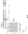
- Each subframe 212 comprises two slots 214, each of 0.5 ms duration.
- Each slot of slots 214 may include seven symbol periods (in the case of normal cyclic prefix (NCP) as shown in FIG. 2A ) or six symbol periods (in the case of extended cyclic prefix (ECP)), with each symbol period for transmission of a symbol. Up to 12 symbols (in the case of ECP) or 14 symbols (in the case of NCP) can be transmitted within subframe 212.
- the symbols can be used to represent, for example, a PRS signal. It is understood that in a 5G network, the number of symbols in one slot can include a different number (other than six or seven) of symbol periods, and a pre-determined pattern of the symbols transmitted in the symbol periods can represent a position measurement signal in the 5G network.
- the available bandwidth may be divided into uniformly spaced orthogonal subcarriers 216.
- subcarriers 216 may be grouped into a group of 12 subcarriers.
- a resource block can include a different number (other than 12 or 15) of subcarriers, and the subcarriers can occur a different channel bandwidth than, for example, the 3 MHz channel bandwidth discussed above.
- a position reference signal which has been defined in 3GPP LTE Release-9 and later releases, may be transmitted by an eNB after appropriate configuration (e.g., by an Operations and Maintenance (O&M) server).
- a PRS may be transmitted in downlink transmissions as a broadcast signal directed to all UEs within a radio range from the eNB, and the PRS can be used by the UEs as a position measurement signal for position determination.
- a PRS can be transmitted in special positioning subframes that are grouped into positioning occasions. For example, in LTE, a PRS positioning occasion can comprise a number N PRS of consecutive positioning subframes where the number N PRS may be between 1 and 160 (e.g. may include the values 1, 2, 4 and 6 as well as other values).
- the PRS positioning occasions for a cell supported by an eNB 170 may occur periodically at intervals, denoted by a number T PRS, of millisecond (or subframe) intervals where T PRS may equal 5, 10, 20, 40, 80, 160, 320, 640, or 1280.
- T PRS may be measured in terms of the number of subframes between the start of consecutive positioning occasions.
- each subcarrier of subcarriers 216 can be paired with a symbol period of slots 214, and the pair forms a resource element.
- a symbol can be generated by converting a digital bitstream into a complex number with an in-phase (I) and quadrature (Q) component, which can then be used to modulate one or more subcarriers.
- I in-phase
- Q quadrature
- a bit value can be mapped to the I and Q component based on the following table: Table 1 b(i) I Q 0 1 / ⁇ 2 1 / ⁇ 2 1 ⁇ 1 / ⁇ 2 ⁇ 1 / ⁇ 2
- one or more subcarriers can have their in-phase frequency components multiplied with a value of 1/ ⁇ 2 and their quadrature components multipled also with a value of 1/ ⁇ 2.
- BPSK is provided here as an illustrative example
- a PRS bitstream can be converted into in-phase and quadrature-phase symbols using other modulation schemes such as quadrature phase shift keying (QPSK), quadrature amplitude modulation (QAM), etc.
- QPSK quadrature phase shift keying
- QAM quadrature amplitude modulation
- a position measurement signal in the 5G network can also include a bitstream which can be converted into in-phase and quadrature-phase symbols using these modulation schemes.
- each bit of a PRS bitstream (and/or a position measurement signal bitstream in the 5G network) can be mapped to a set of subcarrriers within the set of available subcarriers (e.g., frequency bins 0-11 of FIG. 2B ).
- a sequence of radio signals representing a bit of a PRS bitstream (and/or a position measurement signal bitstream in the 5G network) can comprise the set of available subcarriers defined according the resource element mapping mechanism being modulated to represent the bit.
- the modulation information e.g., the in-phase and quadrature values to be multiplied with each of the set of subcarriers
- the frequency domain for each symbol can indicate the amplitude and phase of each subcarrier within the set of available subcarriers as a function of frequency.
- the frequency domain information of each symbol can be fed into an Inverse Fast Fourier Transform (IFFT) processor, which can compute the time-domain data of the in-phase and quadrature components of each of the modulated subcarriers.
- IFFT Inverse Fast Fourier Transform
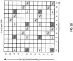
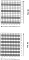
- FIGs. 2B-2E illustrate examples of a resource block.
- the examples of the resources blocks can be for PRS transmission in LTE or for transmission of a position measurement signal in the 5G network.
- FIG. 2B illustrates an example of a resource block with normal cyclic prefix (NCP) for transmission with a single antenna or two antennae (1-or-2 port).
- FIG. 2C illustrates an example of a resource block with normal cyclic prefix (NCP) for transmission with four antennae (4 port).
- FIG. 2D illustrates an example of a resource block with extended cyclic prefix (ECP) for transmission with a single antenna or two antennae (1-or-2 port), whereas FIG.
- NCP normal cyclic prefix
- ECP extended cyclic prefix
- FIG. 2E illustrates an example of a resource block with extended cyclic prefix (ECP) for transmission with four antennae (4 port).
- ECP extended cyclic prefix
- resource elements labelled “R 6 " can be used for transmission of a PRS signal in LTE
- resource elements labelled "R 0 " and “R 1 " are used for transmission of other signals (e.g., cell reference signal (CRS)) in LTE.
- CRS cell reference signal
- a PRS signal in an LTE network may include a modulation pattern of subcarriers 0, 1, 3, 4, 5, 6, 7, 9, 10, and 11 at different symbol periods to form symbols 232, 234, 236, 238, 240, 242, 244, and 246.
- symbol 232 can be transmitted using subcarrier bins 3 and 9 at symbol period 3.
- Symbol 234 can be transmitted using subcarrier bins 1 and 7 at symbol period 5.
- Symbol 236 transmitted using subcarrier bins 0 and 6 at symbol period 6.
- Symbol 238 can be transmitted using subcarrier bins 5 and 11 at symbol period 8.
- Symbol 240 can be transmitted using subcarrier bins 4 and 10 at symbol period 9.
- Symbol 242 can be transmitted using subcarrier bins 3 and 9 at symbol period 10.
- Symbol 244 can be transmitted using subcarrier bins 1 and 7 at symbol period 12.
- Symbol 246 can be transmitted using subcarrier bins 0 and 6 at symbol period 13.
- Different base stations may use different resource elements patterns for transmission of PRS signals to avoid interference among PRS signals from different base stations, and to enable a mobile device to distinguish PRS signals from multiple base stations to perform RSTD determination
- a different base station may use different sets of subcarrier bins for symbols 232, 234, 236, 238, 240, 242, 244, and 246 from the sets of subcarrier bins shown in FIG. 2B .
- the sets of subcarrier bins can be determined by, for example, a resource element mapping function that accepts a physical cell identifier (PCI).
- PCI physical cell identifier
- a mobile device can receive the radio signals comprising the time-domain data symbol, and extract the PRS bitstream from the radio signals.
- the mobile device can use an analog-to-digital converter (ADC) to generate samples of the radio signals, and process the samples using a forward FFT processor to obtain a frequency domain representation of each symbol.
- ADC analog-to-digital converter
- Each tap of the FFT output can correspond to one of the modulated subcarriers.
- An FFT output can correspond to a set of resource elements represented by in-phase and quadrature components of the modulated subcarriers.
- the mobile device can obtain a descrambling sequence generated based on the resource element mapping information, which includes a complex conjugate of each of the modulated subcarriers for each symbol, and perform correlation operation on the FFT output using the descrambling sequence.
- the correlation operation can generate one or more correlation products for each of the symbols that includes a resource element corresponding to the modulated subcarrier.
- the correlation products for each modulated subcarrier can represent the symbol periods in which the subcarrier is modulated to represent the symbols in the symbol periods.
- the correlation products can be averaged to form a frequency domain vector, with each entry of the frequency domain vector representing the amplitude and the phase of a subcarrier bin of a resource block.
- the amplitude and phase information included in the frequency domain vector can be processed using an IFFT processor to generate a time-domain Channel Energy Response (CER).
- CER Channel Energy Response
- a base station does not use each and every subcarrier allocated for the downlink transmission to transmit the subframes containing the PRS signals in an LTE network.
- frequency bins 2 and 8 are not used.
- frequency bins 2, 5, 8, and 11 are not used.
- frequency bins 2, 4, 5, 8, 10, and 11 are not used.
- the non-use of subcarriers in the downlink transmission can lead to periodic and discrete frequency holes in the frequency domain vector generated by the mobile device.
- a frequency domain vector for a PRS signal in an LTE network may include holes every 6 subcarriers.
- the periodic and discrete frequency holes in the frequency domain vector can lead to the time-domain CER including periodic and discrete alias terms. This can be due to the property of Fourier Transform, where periodic and discrete signals in frequency domain become discrete and periodic in the time domain after being processed by inverse Fourier Transform.
- FIG. 2F illustrates an example of a PRS signal reconstructed from downlink transmission using the example resource block of FIG. 2B .
- Ts may be a unit of the time scale and represent 32.6 nanoseconds (ns).
- a base station in a 5G network may be configured to use each subcarrier of a resource block to transmit a position measurement signal, to avoid introducing frequency holes in the frequency domain vector of the signal.
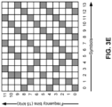
- FIG. 3A-FIG. 5D each of which illustrates an example of resource element mapping in a resource block for transmission of a position measurement signal in a 5G network to mitigate the aliasing effects.
- the position measurement signal can be transmitted during a scheduled transmission occasion using the examples of resource element mapping shown in FIG. 3A-FIG. 5D .
- FIG. 3A-FIG. 5D illustrates an example of resource element mapping in a resource block for transmission of a position measurement signal in a 5G network to mitigate the aliasing effects.
- the position measurement signal can be transmitted during a scheduled transmission occasion using the examples of resource element mapping shown in FIG. 3A-FIG. 5D .
- FIG. 3A-FIG. 5D In each of the illustrative examples of FIG. 3A-FIG.
- each resource block can have up to 14 symbols, and 12 subcarrier bins are allocated. It is understood that the examples of the resource blocks can be applicable for other configurations of a resource block including, for example, extended cyclic prefix are used (such that a resource block includes up to 12 symbols), a different channel bandwidth which changes the number of available subcarriers, etc.
- a position measurement signal can include 14 symbols of the resource blocks, with each symbol using one of the subcarriers in the resource block, and each subcarrier is used at least once (and some are used twice, such as subcarrier bins 0 and 1) for the position measurement signal transmission.
- a position measurement signal can also include 14 symbols, with each symbol using two of the subcarriers in the resource block, and each subcarrier is used at least twice (and some are used for three times, such as subcarrier bins 0, 1, 6, and 7) for the position measurement signal transmission.
- FIG. 3A a position measurement signal can include 14 symbols of the resource blocks, with each symbol using one of the subcarriers in the resource block, and each subcarrier is used at least once (and some are used twice, such as subcarrier bins 0 and 1) for the position measurement signal transmission.
- a position measurement signal can also include 14 symbols, with each symbol using three of the subcarriers in the resource block, and each subcarrier is used at least three times (and some are used four times, such as subcarrier bins 0, 1, 4, 5, 8, and 9) for the PRS signal transmission.
- a position measurement signal can also include 14 symbols, with each symbol using four of the subcarriers in the resource block, and each subcarrier is used at least four times (and some are used five times, such as subcarrier bins 0, 1, 3, 4, 6, 7, 9, and 10) for the position measurement signal transmission.
- a repeating pattern of resource elements mapping among the symbols can be formed, and some of the symbols have identical sets of subcarriers.
- both symbols 0 and 12 use subcarrier bin 0, whereas both symbols 1 and 13 use subcarrier bin 1.
- the subcarrier bin pattern for symbols 0-5 repeats for symbols 6-11.
- the use of repeating patterns of resource elements mapping may be desirable in resource element allocations among base stations for transmissions of a position measurement signal.
- the resource element mapping can be based on one or more equations that outputs the frequency bins based on a symbol number.
- subcarrier_bin0, subcarrier_bin1, and subcarrier_bin2 refer to the subcarrier bin number of, respectively, a first subcarrier, a second subcarrier, and a third subcarrier used for transmission of a symbol associated with a particular symbol number (or symbol period).
- the subcarrier bin numbers can be determined based by performing a modulo operation (mod) on the symbol number by four. For symbols with symbol numbers 0, 4, 8, and 12 (to be transmitted in respectively symbol periods 0, 4, 8, and 12), subcarrier bins 0, 4, and 8 can be obtained from equations 1-3. For symbol number 1, subcarrier bins 1, 5, and 9 can be obtained from the equations.
- the equations can also be updated for different base stations to ensure different subcarriers are used during the same symbol period to reduce interference.
- Subcarrier _ bin 1 symbol _ number mod 4 + 4
- Subcarrier _ bin 2 symbol _ number mod 4 + 9
- a different base station can transmit symbol number 0 with subcarrier bins 1, 5, and 9 (different from subcarrier bins 0, 4, and 8 from equations 1-3), to avoid interference.
- FIG. 3E illustrates an example of resource elements mapping among the symbols which is different from the examples of FIGs. 3A-3D .
- the example of FIG. 3E does not have a pattern of resource elements mapping that repeats itself among the fourteen symbols.
- each subcarrier is also used at least once for the position measurement signal transmission, and the aforementioned aliasing effects can be mitigated.
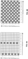
- FIGs. 4A-4C illustrate another set of examples of resource element mapping in a resource block for position measurement signal transmission in a 5G network.
- each subcarrier is used for the same number of times and for transmission of the same number of symbols.
- the position measurement signal includes two symbols (symbol number 0 and symbol number 7), each symbol uses a different set of six subcarriers, and each subcarrier is used once and for transmission of one of the two symbols.
- the position measurement signal includes 14 symbols, each symbol uses a set of six subcarriers (with some symbols using the same set of six subcarriers and some symbols using different sets of six subcarriers), and each subcarrier is used seven times and for transmission of seven symbols.
- the position measurement signal includes four symbols, each symbol uses a set of six carriers, and each subcarrier is used twice and for transmission of two symbols.
- the same number of resource elements is used in each subcarrier for the transmission of symbols, which enables uniform processing of each subcarrier for symbol extraction. For example, as discussed above, as a result of correlation processing, one or more products can be generated for each modulated subcarrier, and the products will be averaged to form the frequency domain vector for PRS signal reconstruction.
- the same number of resource elements for each subcarrier e.g., one resource element in the example of FIG. 4A , seven resource elements in the example of FIG. 4B , two resource elements in the example of FIG.
- each subcarrier can have uniform signal power and signal to noise ratio, which also allows uniform signal processing (e.g., same amplification gain, same noise processing, etc.) for each subcarrier. All these allow more uniform processing of each subcarrier, which in turn can reduce implementation complexity.
- FIGs. 5A-5D illustrate another set of examples of resource element mapping in a resource block for transmission of a position measurement signal in a 5G network.
- each symbol uses each subcarrier of a resource block, resulting in each symbol using the same set of subcarriers for transmission.
- the position measurement signal in these examples can include one symbol (as in FIG. 5A ), two symbols (as in FIG. 5B ), seven symbols (as in FIG. 5C ), four symbols (as in FIG. 5D ), etc.
- the resource elements mapping in FIGs. 5A-5D enables not only uniform processing of each subcarrier (since each subcarrier is used for transmission of same number of symbols) but also uniform processing of each symbol.
- the correlation operation can use the same sequence of complex conjugate values representing the same set of resource elements at the same symbol periods.
- the arrangements in FIGs. 5A-5D allows even more uniform processing of the subcarriers, which can further reduce implementation complexity.
- a signature structure can also be selected to improve signal qualities.
- the selection can be based on one or more metrics related to an operation environment.
- the metrics can be related to various sources of signal quality degradation in the operation environment.
- a signal structure can be selected for transmission of the position measurement signals to adapt to the operation environment, and to improve the qualities of the signals received at a UE.
- the qualities of position measurement signals received at a UE can be affected by Doppler effect when the UE is in motion.
- the Doppler effect can introduce an observed phase shift in the signal received at the UE.
- the observed phase shift can introduce error in the time-domain measurements of signal qualities at the UE. For example, a signal can be measured to have an amplitude A and a phase of zero degrees at a first instance, and the signal can be measured to have the amplitude A and phase of 180 degrees due to the phase shift caused by Doppler effect.
- the two measurements can be combined to provide a measurement of zero (A - A) when, absent the Doppler effect, the combined measurement would have been 2A (A + A).
- the observed phase shift can be related to a multiplication product between the velocity of the UE and a duration of a measurement period. Therefore, a shorter duration of measurement period can be desirable to introduce smaller observed phase shift, and/or to allow a larger UE velocity (and to put less restriction on the movement of the UE) for an error budget corresponding to a target degree of observed phase shiftshifts.
- signal structures can allow shorter duration of measurement periods and can be used to provide positional measurement.
- parameter ⁇ F Doppler can be the observed frequency shift at the UE
- parameter c can be the speed of light
- parameter ⁇ V UE can be the velocity of the UE with respect to the cell stations
- parameter f 0 can be the frequency of transmission of the signals.
- parameter ⁇ can be the observed phase shift
- parameter c can be the speed of light
- parameter ⁇ V UE can be the velocity of the UE with respect to the cell stations
- parameter f 0 can be the frequency of transmission of the signals
- T0 can be the time duration of the signal measurement window period.
- a smaller duration of T0 (for a given combination of ⁇ V UE , f 0 , and c) can lead to a smaller phase shift ⁇ , or can allow for a larger UE velocity ⁇ V UE for a given target phase shift ⁇ .
- a signature structure can be selected to minimize a metric comprising, for example, the observed phase shift, and/or to maximize the allowed UE velocity for a given observed phase shift budget.
- a signal structure can be selected to provide a smaller measurement window period.
- One example of such signal structure may include the signal structures of FIGs. 5A-5D .
- all of the 12 sub-carriers in a resource block are used to represent a symbol.
- the signal structure in FIG. 5A uses all of the 12 sub-carriers to represent a symbol, and one symbol is represented in the resource block, whereas FIGs. 5B-5D includes multiple symbols, with each symbol being represented by the same 12 sub-carriers.
- each symbol is represented by continuous frequency spectrum (since all of the 12 sub-carriers are used) without any frequency hole within the spectrum. Therefore, position measurement can be performed based on a single symbol in the signal structures in FIGs. 5A-5D within a single symbol period.
- the signal structures of FIG. 3A requires a combination of symbols 0-11 to obtain a continuous frequency spectrum within the resource block. Given that symbols 0-11 span 12 symbol periods, the signal structures of FIG. 3A may require a measurement period that is 12 times the measurement period for the signal structures of FIGs. 5A-5D , and can lead to a larger observed phase shift ⁇ . Moreover, for a given target phase shift ⁇ , the signal structures of FIG. 3A allows a UE velocity that is 1/12 of what is allowed by the signal structures of FIGs. 5A-5D . Therefore, in a case where Doppler effect dominates the errors or uncertainties in the position measurement signals (e.g., due to high speed movement of the UE), the signal structures of FIGs. 5A-5D may be preferred over the signal structures of FIG. 3A .
- the qualities of position measurement signals received at the UE can also be affected by timing-varying channel fading effect experienced by the UE.
- Channel fading effect may vary with respect to time due to, for example, a change in the location of the UE, a change in the environment the UE is located, etc., such that the UE can experience different degrees of channel fading at different times.
- the time-varying channel fading effect can introduce a time-varying component that can contaminate the position measurement signals such that the UE may, for example, detect false peaks of position measurement signals and deduce incorrect timing information.
- the signal structure can include a repetitive transmission pattern of subcarriers within a resource block, where each repetitive transmission pattern can be separated by a relatively large time gap. The large time gap can reduce the correlation in the channel fading effect between the repetitive transmission patterns, which can further improve the reduction of the time-varying fading component by averaging.
- the signal structure of FIG. 5B may be more preferable than, for example, the signal structures of FIGs. 3A and 3B .
- a resource block includes two symbols spaced apart by a relative large time gap (e.g., 6 symbol periods) whereas in the signature structure of FIGs. 3A and 3B , there is no time-gap between each symbol.
- a large time gap can reduce the correlation in the channel fading effect between the repetitive transmission patterns, which can further improve the reduction of the time-varying fading component by averaging. Therefore, the signature structure of FIG. 5B may offer better protection against time-varying channel fading effect than the signal structures of FIGs. 3A and 3B .
- the qualities of position measurement signals received at the UE can also be affected by orthogonality between the signals transmitted by different base stations.
- Orthogonality between two signals can refer to lack of overlap in time or frequency between the two signals. The lack of overlap in time and frequency can reduce collision between the two signals.
- the UE performs position measurements based on signals received from a number of geographically distinct transmission points (e.g., different cell stations)
- orthogonality between the signals allows the UE to receive high quality signals from the cell stations simultaneously.
- lack of orthogonality can lead to signal collision and jamming.
- the UE may be close to a very strong serving cell, while also having to measure a very weak neighbor cell.
- the weaker neighbor cell signal may be completely jammed/swamped by the strong serving cell signal, and the UE may be unable to perform measurements based on signals received from the serving cell and from the neighbor cell.
- a signal structure can be selected/configured to allow multiple cell stations to transmit orthogonal position measurement signals, while ensuring that the position measurement signals received from each cell station cover all of the subcarrier frequencies in a resource block.
- the position measurement signal can be represented by one symbol in a resource block (the symbol transmitted at symbol period 0), and the symbol is represented by all of the 12 subcarriers.
- 13 symbol periods are allocated to other cell stations to transmit a single symbol in the same resource block as position measurement signal, and the single symbol can be transmitted at different symbol periods to maintain the orthogonality among the position measurement signals transmitted by cell stations (due to lack of overlap in time).
- the signal structure of FIG. 5B allows fewer base stations to transmit orthogonal position measurement signals. Orthogonality can also be gained from transmission of the signal on different antenna beams at different points in time in cases where a cell is attached to a multi-beam antenna/ antenna array. In such cases a sub-beam would support a smaller coverage area than a similar single wide-beam antenna. Thus, limiting collisions to a smaller geographical area.
- a signal structure can be selected based on, for example, which source of degradation is dominant, which in turn may depend on an operation condition of the UE. For example, if the UE is moving at a high speed (e.g., within a vehicle) such that Doppler effect dominates, signal structures that allow short measurement periods (e.g., any of signal structures FIG. 5A-5D ) can be used.
- signal structures which include repetitive symbols spaced apart by a relative large time gap can be used although, as discussed above, such signal structures can reduce the number of base stations to transmit orthogonal position measurement signals within a resource block than, for example, a signal structure which does not have repetitive symbols within the resource block (e.g., signal structure of FIG. 5A ).
- the signal structure of FIG. 5A may be preferred.
- a base station can determine the operation condition of the UE (e.g., whether the UE moves at high speed, operates in an urban area, uses a position measurement scheme which requires position measurement signals from a large number of sources, etc.), and select a signal structure for the position measurement signals accordingly, and indicate the selection to the UE using the techniques described above.
- the operation condition of the UE e.g., whether the UE moves at high speed, operates in an urban area, uses a position measurement scheme which requires position measurement signals from a large number of sources, etc.
- FIG. 6 is a flow diagram illustrating a method 600 of locating a UE (e.g. UE 105) at a base station, according to an embodiment, which illustrates the functionality of a base station according to aspects of embodiments described above.
- the functionality of one or more blocks illustrated in FIG. 6 may be performed by a base station (e.g., a gNBs 110 and ng-eNB 114 of FIG. 1 ).
- a base station may comprise a computer system
- means for performing these functions may include software and/or hardware components of a computer system, such as the computer system illustrated in FIG. 9 and described in more detail below.
- the functionality of block 610 includes determining, at the base station, a plurality of subcarriers for downlink transmission, wherein the plurality of subcarriers for downlink transmission comprise all subcarriers indicated in a resource block of a scheduled time of transmission within a scheduled transmission occasion, wherein the resource block comprises a plurality of symbol periods, wherein each symbol period of the plurality of symbol periods is for transmission of a symbol using one or more subcarriers of the plurality of subcarriers.
- the plurality of subcarriers for downlink transmission may comprise all subcarriers in a resource block. For example, for a normal length cyclic prefix using 15 kHz spacing, a group of 12 subcarriers may be determined.
- the subcarrier information can be determined based on, for example, the channel bandwidth allocated to the base station for downlink transmission of the positioning measurement signal, a physical identification value assigned to the given cell, or based on other configuration information.
- Means for performing the functionality at block 610 may comprise one or more components of a computer system, such as a bus 905, processing unit(s) 910, communication subsystem 930, working memory 935, operating system 940, application(s) 945, and/or other components of the communication network server 900 illustrated in FIG. 9 and described in more detail below.
- the functionality of block 620 includes transmitting, from the base station, at the scheduled time of transmission, and using each subcarrier of the plurality of subcarriers, a wireless position measurement signal at the scheduled transmission occasion, the wireless position measurement signal being part of a sequence of wireless signals representing a position measurement signal bitstream, wherein the wireless position measurement signal comprises one or more symbols transmitted in one or more symbol periods of the plurality of symbol periods; and wherein a timing of the scheduled transmission occasion of the wireless position measurement signal is such that it enables position measurements to be taken based on the timing.
- the position measurement signal can be part of a sequence of radio/wireless signals representing a PRS bitstream and/or a position measurement signal bitstream in the 5G network.
- the position measurement signal can be broadcasted as a broadcast signal (e.g., which can be picked up by any UE within a pre-determined distance from the base station).
- the position measurement signal can also be targeted at a specific UE.
- the position measurement signal can be transmitted using one or more symbols based on the examples of resource elements mapping as shown, for example, FIGs. 3A-FIG. 5D .
- the resource element mapping patterns can be altered (e.g., by using a different set of resource elements at each symbol period) for different base stations.
- the signal information can be used to modulate one or more subcarriers in one or more symbol periods based on the resource elements mapping to create one or more symbols.
- the symbols can be represented in a frequency domain and by a distribution of amplitudes and phases with respect to frequency.
- the frequency domain information of the symbols can be processed using an IFFT processor to create time-domain data.
- the time-domain data can be broadcasted in the form of radio signals.
- Means for performing the functionality at block 620 may comprise one or more components of a computer system, such as a bus 905, processing unit(s) 910, working memory 935, operating system 940, application(s) 945, and/or other components of the communication network server 900 illustrated in FIG. 9 and described in more detail below.
- FIG. 7 is a flow diagram illustrating a method 700 of locating a UE at the UE, according to an embodiment, which illustrates the functionality of a UE according to aspects of embodiments described above. According to some embodiments, functionality of one or more blocks illustrated in FIG. 7 may be performed by a mobile device including a UE (e.g. UE 105). Means for performing these functions may include software and/or hardware components of a UE 105, as illustrated in FIG. 8 and described in more detail below.
- a UE e.g. UE 105
- Means for performing these functions may include software and/or hardware components of a UE 105, as illustrated in FIG. 8 and described in more detail below.
- the functionality includes receiving, at the mobile device, a sequence of radio signals at a scheduled time within a scheduled transmission occasion.
- the sequence of radio signals may represent, for example, a PRS bitstream, a position measurement signal bitstream in the 5G network, etc.
- the sequence of radio signals can be sampled to generate a set of digital signals.
- Means for performing the functions at block 710 may comprise a bus 805, processing unit(s) 810, wireless communication interface 830, memory 860, GNSS receiver 880, and/or other hardware and/or software components of a UE 105 as illustrated in FIG. 8 and described in more detail below.
- the functionality includes determining, on the mobile device, a plurality of subcarriers for processing the sequence of radio signals, wherein the plurality of subcarriers comprise all subcarriers indicated in a resource block of the scheduled time, wherein the resource block comprises a plurality of symbol periods, wherein each symbol period of the plurality of symbol periods is for transmission of a symbol using one or more subcarriers of the plurality of subcarriers.
- the UE may receive the resource block information based on, for example, assistance data from LPP Means for performing the functions at block 720 may comprise a bus 805, processing unit(s) 810, wireless communication interface 830, memory 860, GNSS receiver 880, and/or other hardware and/or software components of a UE 105 as illustrated in FIG. 8 and described in more detail below.
- the functionality includes processing, on the mobile device, the sequence of radio signals using each of the plurality of subcarriers of the resource block to determine whether the sequence of radio signals represents a position measurement signal bitstream (or a PRS bitstream).
- the processing may include, for example, performing FFT operation on the digital samples of the radio signals to extract one or more resource elements for each symbol, performing correlation operations by multiplying the output of the FFT operation with one or more descrambling sequences including the complex conjugates of the resource elements, and performing averaging of the correlation products for each subcarrier to generate a frequency domain vector.
- the descrambling sequences can be based on the examples of resource elements mapping in FIGs. 3A-5D .
- each subcarrier is modulated the same number of times in a resource block to transmit the symbols (e.g., as in FIGs. 4A-5D ).
- the same number of averaging operations can be performed for each subcarrier.
- the same descrambling sequence can be used to perform correlation for each subcarrier.
- the descrambling sequence can be cell/base station specific, and can be obtained from (or generated based on information obtained from) assistance data from a location server (e.g. LMF 120 of FIG. 1 ).
- the frequency domain vector can then be processed by an IFFT processor to generate time-domain data, which can then be demodulated to recover a bitstream.
- Means for performing the functions at block 730 may comprise a bus 805, processing unit(s) 810, wireless communication interface 830, memory 860, GNSS receiver 880, and/or other hardware and/or software components of a UE 105 as illustrated in FIG. 8 and described in more detail below.
- the functionality includes, responsive to determining that the sequence of radio signals represents the position measurement signal bitstream: determining, on the mobile device, a time of receiving the position measurement signal bitstream based on a result of the processing, and performing, at the mobile device, position measurement based on the time of receiving the position measurement signal bitstream.
- the time can be determined based on, for example, determining a sample timestamp for a peak signal (obtained from block 730) of which the power exceeds a pre-determined threshold.
- the sample timestamp can be used to represent the time of receiving the position measurement signal bitstream.
- the UE can receive position measurement signal bistreams from multiple base stations and measure the peak sample timestamps for the received position measurement signals, and position measurement can be performed based on the sample timestamps. On the other hand, if a position measurement signal stream is not detected from the radio signals at block 730, the UE can proceed to process the next set of received radio signals by proceeding back to, for example, block 710.
- Means for performing the functions at block 740 may comprise a bus 805, processing unit(s) 810, wireless communication interface 830, memory 860, GNSS receiver 880, and/or other hardware and/or software components of a UE 105 as illustrated in FIG. 8 and described in more detail below.
- FIG. 8 illustrates an embodiment of a UE 105, which can be utilized as described herein above (e.g. in association with FIGS. 1-9 ).
- the UE 105 can perform one or more of the functions of method 700 of FIG. 7 .
- FIG. 8 is meant only to provide a generalized illustration of various components, any or all of which may be utilized as appropriate.
- components illustrated by FIG. 8 can be localized to a single physical device and/or distributed among various networked devices, which may be disposed at different physical locations (e.g., located at different parts of a user's body, in which case the components may be communicatively connected via a Personal Area Network (PAN) and/or other means).
- PAN Personal Area Network
- the UE 105 is shown comprising hardware elements that can be electrically coupled via a bus 805 (or may otherwise be in communication, as appropriate).
- the hardware elements may include a processing unit(s) 810 which can include without limitation one or more general-purpose processors, one or more special-purpose processors (such as digital signal processing (DSP) chips, graphics acceleration processors, application specific integrated circuits (ASICs), and/or the like), and/or other processing structure or means.
- DSP digital signal processing
- ASICs application specific integrated circuits
- FIG. 8 some embodiments may have a separate DSP 820, depending on desired functionality. Location determination and/or other determinations based on wireless communication may be provided in the processing unit(s) 810 and/or wireless communication interface 830 (discussed below).
- the UE 105 also can include one or more input devices 870, which can include without limitation a touch screen, a touch pad, microphone, button(s), dial(s), switch(es), and/or the like; and one or more output devices 815, which can include without limitation a display, light emitting diode (LED), speakers, and/or the like.
- input devices 870 can include without limitation a touch screen, a touch pad, microphone, button(s), dial(s), switch(es), and/or the like
- output devices 815 which can include without limitation a display, light emitting diode (LED), speakers, and/or the like.
- LED light emitting diode
- the UE 105 might also include a wireless communication interface 830, which may comprise without limitation a modem, a network card, an infrared communication device, a wireless communication device, and/or a chipset (such as a Bluetooth ® device, an IEEE 802.11 device, an IEEE 802.15.4 device, a Wi-Fi device, a WiMax device, cellular communication facilities, etc.), and/or the like, which may enable the UE 105 to communicate via the networks described above with regard to FIG. 1 .
- the wireless communication interface 830 may permit data to be communicated with a network, eNBs, gNBs, and/or other network components, computer systems, and/or any other electronic devices described herein. The communication can be carried out via one or more wireless communication antenna(s) 832 that send and/or receive wireless signals 834.
- the wireless communication interface 830 may comprise separate transceivers to communicate with base stations (e.g., eNBs and gNBs) and other terrestrial transceivers, such as wireless devices and access points.
- the UE 105 may communicate with different data networks that may comprise various network types.
- a Wireless Wide Area Network may be a Code Division Multiple Access (CDMA) network, a Time Division Multiple Access (TDMA) network, a Frequency Division Multiple Access (FDMA) network, an Orthogonal Frequency Division Multiple Access (OFDMA) network, a Single-Carrier Frequency Division Multiple Access (SC-FDMA) network, a WiMax (IEEE 802.16), and so on.
- CDMA Code Division Multiple Access
- TDMA Time Division Multiple Access
- FDMA Frequency Division Multiple Access
- OFDMA Orthogonal Frequency Division Multiple Access
- SC-FDMA Single-Carrier Frequency Division Multiple Access
- WiMax IEEE 802.16
- a CDMA network may implement one or more radio access technologies (RATs) such as cdma2000, Wideband-CDMA (W-CDMA), and so on.
- Cdma2000 includes IS-95, IS-2000, and/or IS-856 standards.
- a TDMA network may implement Global System for Mobile Communications (GSM), Digital Advanced Mobile Phone System (D-AMPS), or some other RAT.
- GSM Global System for Mobile Communications
- D-AMPS Digital Advanced Mobile Phone System
- An OFDMA network may employ LTE, LTE Advanced, and so on.
- 5G, LTE, LTE Advanced, GSM, and W-CDMA are described in documents from 3GPP.
- Cdma2000 is described in documents from a consortium named "3rd Generation Partnership Project 2" (3GPP2). 3GPP and 3GPP2 documents are publicly available.
- a wireless local area network may also be an IEEE 802.11x network
- a wireless personal area network may be a Bluetooth network, an IEEE 802.15x, or some other type of network.
- the techniques described herein may also be used for any combination of WWAN, WLAN and/or WPAN.
- the UE 105 can further include sensor(s) 840.
- sensors may comprise, without limitation, one or more inertial sensors (e.g., accelerometer(s), gyroscope(s), and or other IMUs), camera(s), magnetometer(s), altimeter(s), microphone(s), proximity sensor(s), light sensor(s), and the like, some of which may be used to complement and/or facilitate the position determination described herein.
- inertial sensors e.g., accelerometer(s), gyroscope(s), and or other IMUs
- camera(s) e.g., camera(s), magnetometer(s), altimeter(s), microphone(s), proximity sensor(s), light sensor(s), and the like, some of which may be used to complement and/or facilitate the position determination described herein.
- Embodiments of the UE 105 may also include a GNSS receiver 880 capable of receiving signals 884 from one or more GNSS satellites (e.g., SVs 190) using an GNSS antenna 882. Such positioning can be utilized to complement and/or incorporate the techniques described herein.
- the GNSS receiver 880 can extract a position of the UE 105, using conventional techniques, from GNSS SVs of a GNSS system, such as Global Positioning System (GPS), Galileo, Glonass, Compass, Quasi-Zenith Satellite System (QZSS) over Japan, Indian Regional Navigational Satellite System (IRNSS) over India, Beidou over China, and/or the like.
- GPS Global Positioning System
- Galileo Galileo
- Glonass Compass
- QZSS Quasi-Zenith Satellite System
- IRNSS Indian Regional Navigational Satellite System
- Beidou Beidou over China
- the GNSS receiver 880 can be used with various augmentation systems (e.g., a Satellite Based Augmentation System (SBAS)) that may be associated with or otherwise enabled for use with one or more global and/or regional navigation satellite systems.
- SBAS Satellite Based Augmentation System
- an SBAS may include an augmentation system(s) that provides integrity information, differential corrections, etc., such as, e.g., Wide Area Augmentation System (WAAS), European Geostationary Navigation Overlay Service (EGNOS), Multi -functional Satellite Augmentation System (MSAS), GPS Aided Geo Augmented Navigation or GPS and Geo Augmented Navigation system (GAGAN), and/or the like.
- WAAS Wide Area Augmentation System
- EGNOS European Geostationary Navigation Overlay Service
- MSAS Multi -functional Satellite Augmentation System
- GPS Aided Geo Augmented Navigation or GPS and Geo Augmented Navigation system (GAGAN) GPS Aided Geo Augmented Navigation or GPS and Geo Augmented Navigation system (GAGAN), and/or the like.
- a GNSS may include any combination of one or more global and/or regional navigation satellite systems and/or augmentation systems, and GNSS signals may include GNSS, GNSS -like, and/or other signals associated with such one or more GNSS.
- the UE 105 may further include and/or be in communication with a memory 860.
- the memory 860 can include, without limitation, local and/or network accessible storage, a disk drive, a drive array, an optical storage device, a solid-state storage device, such as a random access memory (“RAM”), and/or a read-only memory (“ROM”), which can be programmable, flash-updateable, and/or the like.
- RAM random access memory
- ROM read-only memory
- Such storage devices may be configured to implement any appropriate data stores, including without limitation, various file systems, database structures, and/or the like.
- the memory 860 of the UE 105 also can comprise software elements (not shown in FIG. 8 ), including an operating system, device drivers, executable libraries, and/or other code, such as one or more application programs, which may comprise computer programs provided by various embodiments, and/or may be designed to implement methods, and/or configure systems, provided by other embodiments, as described herein.
- one or more procedures described with respect to the method(s) discussed above may be implemented as code and/or instructions executable by the UE 105 (and/or processing unit(s) 810 or DSP 820 within UE 105).
- code and/or instructions can be used to configure and/or adapt a general purpose computer (or other device) to perform one or more operations in accordance with the described methods.
- FIG. 9 illustrates an embodiment of a communication network server 900, which may be utilized and/or incorporated into one or more components of a communication system (e.g., communication system 100 of FIG. 1 ), including various components, a 5G network, including the 5G RAN and 5GC, and/or similar components of other network types.
- FIG. 9 provides a schematic illustration of one embodiment of a communication network server 900 that can perform the methods provided by various other embodiments, such as the method described in relation to FIG. 6 . It should be noted that FIG. 9 is meant only to provide a generalized illustration of various components, any or all of which may be utilized as appropriate. FIG. 9 , therefore, broadly illustrates how individual system elements may be implemented in a relatively separated or relatively more integrated manner.
- communication network server 900 may correspond to an LMF 120, a gNB 110 (e.g. gNB 110-1), an eNB, an E-SMLC, a SUPL SLP and/or some other type of location-capable device.
- Communication network server 900 is shown comprising hardware elements that can be electrically coupled via a bus 905 (or may otherwise be in communication, as appropriate).
- the hardware elements may include processing unit(s) 910, which can include without limitation one or more general-purpose processors, one or more special-purpose processors (such as digital signal processing chips, graphics acceleration processors, and/or the like), and/or other processing structure, which can be configured to perform one or more of the methods described herein, including the method described in relation to FIG. 6 .
- Communication network server 900 also can include one or more input devices 915, which can include without limitation a mouse, a keyboard, a camera, a microphone, and/or the like; and one or more output devices 920, which can include without limitation a display device, a printer, and/or the like.
- input devices 915 can include without limitation a mouse, a keyboard, a camera, a microphone, and/or the like
- output devices 920 which can include without limitation a display device, a printer, and/or the like.
- Communication network server 900 may further include (and/or be in communication with) one or more non-transitory storage devices 925, which can comprise, without limitation, local and/or network accessible storage, and/or can include, without limitation, a disk drive, a drive array, an optical storage device, a solid-state storage device, such as a random access memory (“RAM”), and/or a read-only memory (“ROM”), which can be programmable, flash-updateable, and/or the like.
- RAM random access memory
- ROM read-only memory
- Such storage devices may be configured to implement any appropriate data stores, including without limitation, various file systems, database structures, and/or the like.
- Communication network server 900 may also include a communications subsystem 930, which can include support of wireline communication technologies and/or wireless communication technologies (in some embodiments) managed and controlled by a wireless communication interface 933.
- the communications subsystem 930 may include a modem, a network card (wireless or wired), an infrared communication device, a wireless communication device, and/or a chipset, and/or the like.
- the communications subsystem 930 may include one or more input and/or output communication interfaces, such as the wireless communication interface 933, to permit data to be exchanged with a network, mobile devices, other computer systems, and/or any other electronic devices described herein.
- mobile device and “UE” are used interchangeably herein to refer to any mobile communications device such as, but not limited to, mobile phones, smartphones, wearable devices, mobile computing devices (e.g., laptops, PDAs, tablets), embedded modems, and automotive and other vehicular computing devices.
- mobile communications device such as, but not limited to, mobile phones, smartphones, wearable devices, mobile computing devices (e.g., laptops, PDAs, tablets), embedded modems, and automotive and other vehicular computing devices.
- communication network server 900 will further comprise a working memory 935, which can include a RAM and/or ROM device.
- Software elements shown as being located within the working memory 935, can include an operating system 940, device drivers, executable libraries, and/or other code, such as application(s) 945, which may comprise computer programs provided by various embodiments, and/or may be designed to implement methods, and/or configure systems, provided by other embodiments, as described herein.
- application(s) 945 which may comprise computer programs provided by various embodiments, and/or may be designed to implement methods, and/or configure systems, provided by other embodiments, as described herein.
- code and/or instructions may be implemented as code and/or instructions executable by a computer (and/or a processing unit within a computer); in an aspect, then, such code and/or instructions can be used to configure and/or adapt a general purpose computer (or other device) to perform one or more operations in accordance with the described methods.
- a set of these instructions and/or code might be stored on a non-transitory computer-readable storage medium, such as the storage device(s) 925 described above.
- the storage medium might be incorporated within a computer system, such as communication network server 900.
- the storage medium might be separate from a computer system (e.g., a removable medium, such as an optical disc), and/or provided in an installation package, such that the storage medium can be used to program, configure, and/or adapt a general purpose computer with the instructions/code stored thereon.
- These instructions might take the form of executable code, which is executable by communication network server 900 and/or might take the form of source and/or installable code, which, upon compilation and/or installation on communication network server 900 (e.g., using any of a variety of generally available compilers, installation programs, compression/decompression utilities, etc.), then takes the form of executable code.
- FIG. 10 illustrates an embodiment of a base station 1000, which can be utilized as described herein above (e.g. in association with FIGS. 1-7 ).
- base station 1000 can perform one or more of the functions of method 600 of FIG. 6 .
- FIG. 10 is meant only to provide a generalized illustration of various components, any or all of which may be utilized as appropriate.
- the base station 1000 may correspond to an LMF 120, a gNB 110, an ng-eNB 114 as described herein above.
- the base station 1000 is shown comprising hardware elements that can be electrically coupled via a bus 1005 (or may otherwise be in communication, as appropriate).
- the hardware elements may include a processing unit(s) 1010 which can include without limitation one or more general-purpose processors, one or more special-purpose processors (such as digital signal processing (DSP) chips, graphics acceleration processors, application specific integrated circuits (ASICs), and/or the like), and/or other processing structure or means.
- DSP Digital Signal Processor
- Location determination and/or other determinations based on wireless communication may be provided in the processing unit(s) 1010 and/or wireless communication interface 1030 (discussed below).
- the base station 1000 also can include one or more input devices 1070, which can include without limitation a keyboard, display, mouse, microphone, button(s), dial(s), switch(es), and/or the like; and one or more output devices 1015, which can include without limitation a display, light emitting diode (LED), speakers, and/or the like.
- input devices 1070 can include without limitation a keyboard, display, mouse, microphone, button(s), dial(s), switch(es), and/or the like
- output devices 1015 which can include without limitation a display, light emitting diode (LED), speakers, and/or the like.
- LED light emitting diode
- the base station 1000 might also include a wireless communication interface 1030, which may comprise without limitation a modem, a network card, an infrared communication device, a wireless communication device, and/or a chipset (such as a Bluetooth ® device, an IEEE 802.11 device, an IEEE 802.15.4 device, a WiFi device, a WiMax device, cellular communication facilities, etc.), and/or the like, which may enable the base station 1000 to communicate as described herein.
- the wireless communication interface 1030 may permit data and signaling to be communicated (e.g. transmitted and received) UEs, other base stations (e.g., eNBs, gNBs, and ng-eNBs), and/or other network components, computer systems, and/or any other electronic devices described herein.
- the communication can be carried out via one or more wireless communication antenna(s) 1032 that send and/or receive wireless signals 934.
- Base station 1000 may also include a network interface 1080, which can include support of wireline communication technologies.
- Network interface 1080 may include a modem, network card, chipset, and/or the like.
- Network interface 1080 may include one or more input and/or output communication interfaces to permit data to be exchanged with a network, communication network servers, computer systems, and/or any other electronic devices described herein.
- base station 1000 will further comprise a memory 1060.
- Memory 1060 can include, without limitation, local and/or network accessible storage, a disk drive, a drive array, an optical storage device, a solid-state storage device, such as a RAM, and/or a ROM, which can be programmable, flash-updateable, and/or the like.
- Such storage devices may be configured to implement any appropriate data stores, including without limitation, various file systems, database structures, and/or the like.
- Memory 1060 of the base station 1000 also can comprise software elements (not shown in FIG. 10 ), including an operating system, device drivers, executable libraries, and/or other code, such as one or more application programs, which may comprise computer programs provided by various embodiments, and/or may be designed to implement methods, and/or configure systems, provided by other embodiments, as described herein.
- one or more procedures described with respect to the method(s) discussed above may be implemented as code and/or instructions in memory 1060 that are executable by base station 1000 (and/or processing unit(s) 910 or DSP 1020 within base station 1000).
- code and/or instructions can be used to configure and/or adapt a general purpose computer (or other device) to perform one or more operations in accordance with the described methods.
- components that can include memory can include non-transitory machine-readable media.
- machine-readable medium and “computer-readable medium” as used herein, refer to any storage medium that participates in providing data that causes a machine to operate in a specific fashion.
- various machine-readable media might be involved in providing instructions/code to processing units and/or other device(s) for execution. Additionally or alternatively, the machine-readable media might be used to store and/or carry such instructions/code.
- a computer-readable medium is a physical and/or tangible storage medium. Such a medium may take many forms, including but not limited to, non-volatile media, volatile media, and transmission media.
- Computer-readable media include, for example, magnetic and/or optical media, punchcards, papertape, any other physical medium with patterns of holes, a RAM, a PROM, EPROM, a FLASH-EPROM, any other memory chip or cartridge, a carrier wave as described hereinafter, or any other medium from which a computer can read instructions and/or code.
- a special purpose computer or a similar special purpose electronic computing device is capable of manipulating or transforming signals, typically represented as physical electronic, electrical, or magnetic quantities within memories, registers, or other information storage devices, transmission devices, or display devices of the special purpose computer or similar special purpose electronic computing device.
- the term "at least one of” if used to associate a list, such as A, B, or C, can be interpreted to mean any combination of A, B, and/or C, such as A, AB, AA, AAB, AABBCCC, etc.
Landscapes
- Engineering & Computer Science (AREA)
- Computer Networks & Wireless Communication (AREA)
- Signal Processing (AREA)
- Physics & Mathematics (AREA)
- General Physics & Mathematics (AREA)
- Radar, Positioning & Navigation (AREA)
- Remote Sensing (AREA)
- Mobile Radio Communication Systems (AREA)
- Position Fixing By Use Of Radio Waves (AREA)
- Radar Systems Or Details Thereof (AREA)
Applications Claiming Priority (3)
| Application Number | Priority Date | Filing Date | Title |
|---|---|---|---|
| US201862652243P | 2018-04-03 | 2018-04-03 | |
| US16/107,713 US11750346B2 (en) | 2018-04-03 | 2018-08-21 | Signal structure for navigation and positioning signals |
| PCT/US2019/020556 WO2019194921A1 (en) | 2018-04-03 | 2019-03-04 | Signal structure for navigation and positioning signals |
Publications (3)
| Publication Number | Publication Date |
|---|---|
| EP3775969A1 EP3775969A1 (en) | 2021-02-17 |
| EP3775969C0 EP3775969C0 (en) | 2024-05-29 |
| EP3775969B1 true EP3775969B1 (en) | 2024-05-29 |
Family
ID=68057303
Family Applications (1)
| Application Number | Title | Priority Date | Filing Date |
|---|---|---|---|
| EP19711776.5A Active EP3775969B1 (en) | 2018-04-03 | 2019-03-04 | Signal structure for navigation and positioning signals |
Country Status (9)
| Country | Link |
|---|---|
| US (1) | US11750346B2 (https=) |
| EP (1) | EP3775969B1 (https=) |
| JP (1) | JP7295880B2 (https=) |
| KR (1) | KR102794289B1 (https=) |
| CN (1) | CN111919133B (https=) |
| AU (1) | AU2019248434B2 (https=) |
| BR (1) | BR112020020151A2 (https=) |
| TW (1) | TWI821249B (https=) |
| WO (1) | WO2019194921A1 (https=) |
Families Citing this family (12)
| Publication number | Priority date | Publication date | Assignee | Title |
|---|---|---|---|---|
| US10659270B2 (en) * | 2018-10-10 | 2020-05-19 | At&T Intellectual Property I, L.P. | Mapping reference signals in wireless communication systems to avoid repetition |
| MX2021011138A (es) * | 2019-03-19 | 2021-10-19 | Ericsson Telefon Ab L M | Estimacion de estado de equipo de usuario. |
| US11012211B2 (en) * | 2019-10-07 | 2021-05-18 | Jaihyung Cho | Method for transmitting reference signal and apparatus using the same |
| US11422223B2 (en) | 2019-10-10 | 2022-08-23 | Qualcomm Incorporated | Method and apparatus for 5G positioning accuracy improvement in presence of phase noise |
| WO2021167715A1 (en) | 2020-02-21 | 2021-08-26 | Qualcomm Incorporated | Positioning reference signal processing |
| BR112022016172A2 (pt) * | 2020-02-24 | 2022-10-04 | Qualcomm Inc | Codificação de informações de controle de enlace ascendente (uci) de duas partes para relatórios de informações de estado de posicionamento (psi) para posicionamento de baixa latência |
| US11563538B2 (en) * | 2020-03-11 | 2023-01-24 | Qualcomm Incorporated | Signal structure for terrestrial timing and positioning system |
| JP7595679B2 (ja) * | 2020-03-26 | 2024-12-06 | クゥアルコム・インコーポレイテッド | 少なくとも1つの測位状態情報(psi)報告要素の延期された報告のための方法および装置 |
| US11729039B2 (en) | 2020-08-31 | 2023-08-15 | Sinclair Broadcast Group, Inc. | ATSC 3.0 single frequency networks used for positioning navigation timing and synergy 4G / 5G networks |
| CN112612040B (zh) * | 2020-12-11 | 2022-12-09 | 紫光展锐(重庆)科技有限公司 | 一种全球导航卫星系统gnss启动方法及装置 |
| US11445470B2 (en) * | 2021-02-02 | 2022-09-13 | Qualcomm Incorporated | Position measurement in presence of MBSFN signals |
| CN117242841A (zh) * | 2021-05-07 | 2023-12-15 | 高通股份有限公司 | 用于提前调度定位以进一步减少等待时间的优化 |
Citations (3)
| Publication number | Priority date | Publication date | Assignee | Title |
|---|---|---|---|---|
| EP2418887A2 (en) * | 2009-04-10 | 2012-02-15 | LG Electronics Inc. | Method and apparatus for transmitting positioning reference signal in wireless communication system |
| US20130308567A1 (en) * | 2012-05-15 | 2013-11-21 | Qualcomm Incorporated | Methods and apparatus for positioning reference signals in a new carrier type |
| WO2016163943A1 (en) * | 2015-04-10 | 2016-10-13 | Telefonaktiebolaget Lm Ericsson (Publ) | Enhanced positioning reference signal patterns for positioning |
Family Cites Families (13)
| Publication number | Priority date | Publication date | Assignee | Title |
|---|---|---|---|---|
| US8218420B2 (en) * | 2009-03-26 | 2012-07-10 | Ntt Docomo, Inc. | Non-cyclic evolving-type user resource structure for OFDMA based system with null guard tones |
| US8730925B2 (en) * | 2009-04-09 | 2014-05-20 | Motorola Mobility Llc | Method and apparatus for generating reference signals for accurate time-difference of arrival estimation |
| WO2010117116A1 (ko) | 2009-04-10 | 2010-10-14 | (주)팬택 | 모듈러 소나 시퀀스를 이용한 신호 패턴의 생성방법 및 그 장치 |
| US8467346B2 (en) | 2009-06-19 | 2013-06-18 | Futurewei Technologies, Inc. | Method and apparatus for generating time-frequency patterns for reference signal in an OFDM wireless communication system |
| US8891480B2 (en) * | 2009-07-01 | 2014-11-18 | Qualcomm Incorporated | Positioning reference signals in a telecommunication system |
| US8948040B2 (en) * | 2010-09-05 | 2015-02-03 | Lg Electronics Inc. | Method and device for deciding location of terminal in a wireless communication system |
| CN105099634B (zh) * | 2014-05-09 | 2019-05-07 | 中兴通讯股份有限公司 | 动态资源的分配方法及装置、基站、终端 |
| KR102347722B1 (ko) * | 2015-04-10 | 2022-01-06 | 삼성전자주식회사 | 무선 통신 시스템에서 위치 측정을 위한 장치 및 방법 |
| US11212760B2 (en) * | 2015-09-24 | 2021-12-28 | Qualcomm Incorporated | Common synchronization channel design for narrowband communications |
| EP3360201B1 (en) | 2015-10-08 | 2021-07-07 | PoLTE Corporation | Angle of arrival positioning system for tracking objects |
| US10317509B2 (en) | 2016-03-31 | 2019-06-11 | Qualcomm Incorporated | PRS-based terrestrial beacon system (TBS) implementations |
| JP6773945B2 (ja) * | 2016-08-04 | 2020-10-21 | シャープ株式会社 | 基地局装置、ロケーションサーバ装置、および通信方法 |
| US11122455B2 (en) * | 2017-02-28 | 2021-09-14 | Lg Electronics Inc. | Method for positioning terminal in wireless communication system and apparatus therefor |
-
2018
- 2018-08-21 US US16/107,713 patent/US11750346B2/en active Active
-
2019
- 2019-03-04 KR KR1020207031209A patent/KR102794289B1/ko active Active
- 2019-03-04 JP JP2020553635A patent/JP7295880B2/ja active Active
- 2019-03-04 BR BR112020020151-0A patent/BR112020020151A2/pt unknown
- 2019-03-04 WO PCT/US2019/020556 patent/WO2019194921A1/en not_active Ceased
- 2019-03-04 AU AU2019248434A patent/AU2019248434B2/en active Active
- 2019-03-04 CN CN201980022583.9A patent/CN111919133B/zh active Active
- 2019-03-04 EP EP19711776.5A patent/EP3775969B1/en active Active
- 2019-03-05 TW TW108107289A patent/TWI821249B/zh active
Patent Citations (3)
| Publication number | Priority date | Publication date | Assignee | Title |
|---|---|---|---|---|
| EP2418887A2 (en) * | 2009-04-10 | 2012-02-15 | LG Electronics Inc. | Method and apparatus for transmitting positioning reference signal in wireless communication system |
| US20130308567A1 (en) * | 2012-05-15 | 2013-11-21 | Qualcomm Incorporated | Methods and apparatus for positioning reference signals in a new carrier type |
| WO2016163943A1 (en) * | 2015-04-10 | 2016-10-13 | Telefonaktiebolaget Lm Ericsson (Publ) | Enhanced positioning reference signal patterns for positioning |
Also Published As
| Publication number | Publication date |
|---|---|
| US11750346B2 (en) | 2023-09-05 |
| AU2019248434A1 (en) | 2020-09-17 |
| CN111919133B (zh) | 2024-06-14 |
| JP2021520709A (ja) | 2021-08-19 |
| AU2019248434B2 (en) | 2024-06-20 |
| EP3775969C0 (en) | 2024-05-29 |
| KR102794289B1 (ko) | 2025-04-09 |
| BR112020020151A2 (pt) | 2021-01-05 |
| TWI821249B (zh) | 2023-11-11 |
| US20190305901A1 (en) | 2019-10-03 |
| TW201943290A (zh) | 2019-11-01 |
| EP3775969A1 (en) | 2021-02-17 |
| JP7295880B2 (ja) | 2023-06-21 |
| CN111919133A (zh) | 2020-11-10 |
| KR20200140306A (ko) | 2020-12-15 |
| WO2019194921A1 (en) | 2019-10-10 |
Similar Documents
| Publication | Publication Date | Title |
|---|---|---|
| EP3775969B1 (en) | Signal structure for navigation and positioning signals | |
| AU2023202072B2 (en) | Navigation and positioning system using radio beam | |
| EP3775960B1 (en) | Disentangled orthogonal frequency division multiplexing for navigation and positioning signals | |
| KR102746074B1 (ko) | 비동기식 차량 네트워크들에서의 그룹-기반 포지셔닝 설계 | |
| EP4320947B1 (en) | Positioning reference signal (prs) securitization in user equipment (ue) positioning | |
| US20240142564A1 (en) | Distributing receive chains for parallel processing of reference signals from multiple sources | |
| EP3777296B1 (en) | Orthogonality and encapsulation for positioning and navigation signals |
Legal Events
| Date | Code | Title | Description |
|---|---|---|---|
| STAA | Information on the status of an ep patent application or granted ep patent |
Free format text: STATUS: UNKNOWN |
|
| STAA | Information on the status of an ep patent application or granted ep patent |
Free format text: STATUS: THE INTERNATIONAL PUBLICATION HAS BEEN MADE |
|
| PUAI | Public reference made under article 153(3) epc to a published international application that has entered the european phase |
Free format text: ORIGINAL CODE: 0009012 |
|
| STAA | Information on the status of an ep patent application or granted ep patent |
Free format text: STATUS: REQUEST FOR EXAMINATION WAS MADE |
|
| 17P | Request for examination filed |
Effective date: 20201002 |
|
| AK | Designated contracting states |
Kind code of ref document: A1 Designated state(s): AL AT BE BG CH CY CZ DE DK EE ES FI FR GB GR HR HU IE IS IT LI LT LU LV MC MK MT NL NO PL PT RO RS SE SI SK SM TR |
|
| AX | Request for extension of the european patent |
Extension state: BA ME |
|
| DAV | Request for validation of the european patent (deleted) | ||
| DAX | Request for extension of the european patent (deleted) | ||
| STAA | Information on the status of an ep patent application or granted ep patent |
Free format text: STATUS: EXAMINATION IS IN PROGRESS |
|
| 17Q | First examination report despatched |
Effective date: 20220830 |
|
| REG | Reference to a national code |
Ref country code: DE Ref legal event code: R079 Free format text: PREVIOUS MAIN CLASS: G01S0005100000 Ipc: G01S0001040000 Ref country code: DE Ref legal event code: R079 Ref document number: 602019052886 Country of ref document: DE Free format text: PREVIOUS MAIN CLASS: G01S0005100000 Ipc: G01S0001040000 |
|
| GRAP | Despatch of communication of intention to grant a patent |
Free format text: ORIGINAL CODE: EPIDOSNIGR1 |
|
| RIC1 | Information provided on ipc code assigned before grant |
Ipc: H04W 64/00 20090101ALI20231128BHEP Ipc: G01S 5/10 20060101ALI20231128BHEP Ipc: G01S 1/04 20060101AFI20231128BHEP |
|
| STAA | Information on the status of an ep patent application or granted ep patent |
Free format text: STATUS: GRANT OF PATENT IS INTENDED |
|
| INTG | Intention to grant announced |
Effective date: 20240104 |
|
| GRAS | Grant fee paid |
Free format text: ORIGINAL CODE: EPIDOSNIGR3 |
|
| GRAA | (expected) grant |
Free format text: ORIGINAL CODE: 0009210 |
|
| STAA | Information on the status of an ep patent application or granted ep patent |
Free format text: STATUS: THE PATENT HAS BEEN GRANTED |
|
| AK | Designated contracting states |
Kind code of ref document: B1 Designated state(s): AL AT BE BG CH CY CZ DE DK EE ES FI FR GB GR HR HU IE IS IT LI LT LU LV MC MK MT NL NO PL PT RO RS SE SI SK SM TR |
|
| REG | Reference to a national code |
Ref country code: CH Ref legal event code: EP |
|
| REG | Reference to a national code |
Ref country code: IE Ref legal event code: FG4D |
|
| REG | Reference to a national code |
Ref country code: DE Ref legal event code: R096 Ref document number: 602019052886 Country of ref document: DE |
|
| U01 | Request for unitary effect filed |
Effective date: 20240612 |
|
| U07 | Unitary effect registered |
Designated state(s): AT BE BG DE DK EE FI FR IT LT LU LV MT NL PT SE SI Effective date: 20240621 |
|
| PG25 | Lapsed in a contracting state [announced via postgrant information from national office to epo] |
Ref country code: IS Free format text: LAPSE BECAUSE OF FAILURE TO SUBMIT A TRANSLATION OF THE DESCRIPTION OR TO PAY THE FEE WITHIN THE PRESCRIBED TIME-LIMIT Effective date: 20240929 |
|
| PG25 | Lapsed in a contracting state [announced via postgrant information from national office to epo] |
Ref country code: HR Free format text: LAPSE BECAUSE OF FAILURE TO SUBMIT A TRANSLATION OF THE DESCRIPTION OR TO PAY THE FEE WITHIN THE PRESCRIBED TIME-LIMIT Effective date: 20240529 |
|
| PG25 | Lapsed in a contracting state [announced via postgrant information from national office to epo] |
Ref country code: GR Free format text: LAPSE BECAUSE OF FAILURE TO SUBMIT A TRANSLATION OF THE DESCRIPTION OR TO PAY THE FEE WITHIN THE PRESCRIBED TIME-LIMIT Effective date: 20240830 |
|
| PG25 | Lapsed in a contracting state [announced via postgrant information from national office to epo] |
Ref country code: ES Free format text: LAPSE BECAUSE OF FAILURE TO SUBMIT A TRANSLATION OF THE DESCRIPTION OR TO PAY THE FEE WITHIN THE PRESCRIBED TIME-LIMIT Effective date: 20240529 |
|
| PG25 | Lapsed in a contracting state [announced via postgrant information from national office to epo] |
Ref country code: PL Free format text: LAPSE BECAUSE OF FAILURE TO SUBMIT A TRANSLATION OF THE DESCRIPTION OR TO PAY THE FEE WITHIN THE PRESCRIBED TIME-LIMIT Effective date: 20240529 |
|
| PG25 | Lapsed in a contracting state [announced via postgrant information from national office to epo] |
Ref country code: PL Free format text: LAPSE BECAUSE OF FAILURE TO SUBMIT A TRANSLATION OF THE DESCRIPTION OR TO PAY THE FEE WITHIN THE PRESCRIBED TIME-LIMIT Effective date: 20240529 Ref country code: NO Free format text: LAPSE BECAUSE OF FAILURE TO SUBMIT A TRANSLATION OF THE DESCRIPTION OR TO PAY THE FEE WITHIN THE PRESCRIBED TIME-LIMIT Effective date: 20240829 Ref country code: IS Free format text: LAPSE BECAUSE OF FAILURE TO SUBMIT A TRANSLATION OF THE DESCRIPTION OR TO PAY THE FEE WITHIN THE PRESCRIBED TIME-LIMIT Effective date: 20240929 Ref country code: HR Free format text: LAPSE BECAUSE OF FAILURE TO SUBMIT A TRANSLATION OF THE DESCRIPTION OR TO PAY THE FEE WITHIN THE PRESCRIBED TIME-LIMIT Effective date: 20240529 Ref country code: GR Free format text: LAPSE BECAUSE OF FAILURE TO SUBMIT A TRANSLATION OF THE DESCRIPTION OR TO PAY THE FEE WITHIN THE PRESCRIBED TIME-LIMIT Effective date: 20240830 Ref country code: ES Free format text: LAPSE BECAUSE OF FAILURE TO SUBMIT A TRANSLATION OF THE DESCRIPTION OR TO PAY THE FEE WITHIN THE PRESCRIBED TIME-LIMIT Effective date: 20240529 Ref country code: RS Free format text: LAPSE BECAUSE OF FAILURE TO SUBMIT A TRANSLATION OF THE DESCRIPTION OR TO PAY THE FEE WITHIN THE PRESCRIBED TIME-LIMIT Effective date: 20240829 |
|
| PG25 | Lapsed in a contracting state [announced via postgrant information from national office to epo] |
Ref country code: CZ Free format text: LAPSE BECAUSE OF FAILURE TO SUBMIT A TRANSLATION OF THE DESCRIPTION OR TO PAY THE FEE WITHIN THE PRESCRIBED TIME-LIMIT Effective date: 20240529 |
|
| PG25 | Lapsed in a contracting state [announced via postgrant information from national office to epo] |
Ref country code: SK Free format text: LAPSE BECAUSE OF FAILURE TO SUBMIT A TRANSLATION OF THE DESCRIPTION OR TO PAY THE FEE WITHIN THE PRESCRIBED TIME-LIMIT Effective date: 20240529 Ref country code: RO Free format text: LAPSE BECAUSE OF FAILURE TO SUBMIT A TRANSLATION OF THE DESCRIPTION OR TO PAY THE FEE WITHIN THE PRESCRIBED TIME-LIMIT Effective date: 20240529 |
|
| PG25 | Lapsed in a contracting state [announced via postgrant information from national office to epo] |
Ref country code: SM Free format text: LAPSE BECAUSE OF FAILURE TO SUBMIT A TRANSLATION OF THE DESCRIPTION OR TO PAY THE FEE WITHIN THE PRESCRIBED TIME-LIMIT Effective date: 20240529 |
|
| PG25 | Lapsed in a contracting state [announced via postgrant information from national office to epo] |
Ref country code: SM Free format text: LAPSE BECAUSE OF FAILURE TO SUBMIT A TRANSLATION OF THE DESCRIPTION OR TO PAY THE FEE WITHIN THE PRESCRIBED TIME-LIMIT Effective date: 20240529 Ref country code: SK Free format text: LAPSE BECAUSE OF FAILURE TO SUBMIT A TRANSLATION OF THE DESCRIPTION OR TO PAY THE FEE WITHIN THE PRESCRIBED TIME-LIMIT Effective date: 20240529 Ref country code: RO Free format text: LAPSE BECAUSE OF FAILURE TO SUBMIT A TRANSLATION OF THE DESCRIPTION OR TO PAY THE FEE WITHIN THE PRESCRIBED TIME-LIMIT Effective date: 20240529 Ref country code: CZ Free format text: LAPSE BECAUSE OF FAILURE TO SUBMIT A TRANSLATION OF THE DESCRIPTION OR TO PAY THE FEE WITHIN THE PRESCRIBED TIME-LIMIT Effective date: 20240529 |
|
| U20 | Renewal fee for the european patent with unitary effect paid |
Year of fee payment: 7 Effective date: 20250211 |
|
| PLBE | No opposition filed within time limit |
Free format text: ORIGINAL CODE: 0009261 |
|
| STAA | Information on the status of an ep patent application or granted ep patent |
Free format text: STATUS: NO OPPOSITION FILED WITHIN TIME LIMIT |
|
| 26N | No opposition filed |
Effective date: 20250303 |
|
| PG25 | Lapsed in a contracting state [announced via postgrant information from national office to epo] |
Ref country code: MC Free format text: LAPSE BECAUSE OF FAILURE TO SUBMIT A TRANSLATION OF THE DESCRIPTION OR TO PAY THE FEE WITHIN THE PRESCRIBED TIME-LIMIT Effective date: 20240529 |
|
| REG | Reference to a national code |
Ref country code: CH Ref legal event code: H13 Free format text: ST27 STATUS EVENT CODE: U-0-0-H10-H13 (AS PROVIDED BY THE NATIONAL OFFICE) Effective date: 20251023 |
|
| PG25 | Lapsed in a contracting state [announced via postgrant information from national office to epo] |
Ref country code: CH Free format text: LAPSE BECAUSE OF NON-PAYMENT OF DUE FEES Effective date: 20250331 |
|
| U20 | Renewal fee for the european patent with unitary effect paid |
Year of fee payment: 8 Effective date: 20260211 |
|
| PGFP | Annual fee paid to national office [announced via postgrant information from national office to epo] |
Ref country code: GB Payment date: 20260211 Year of fee payment: 8 |
|
| PGFP | Annual fee paid to national office [announced via postgrant information from national office to epo] |
Ref country code: IE Payment date: 20260209 Year of fee payment: 8 |