EP3775598B1 - Automatic interbrake pads distance adjuster - Google Patents
Automatic interbrake pads distance adjuster Download PDFInfo
- Publication number
- EP3775598B1 EP3775598B1 EP19830251.5A EP19830251A EP3775598B1 EP 3775598 B1 EP3775598 B1 EP 3775598B1 EP 19830251 A EP19830251 A EP 19830251A EP 3775598 B1 EP3775598 B1 EP 3775598B1
- Authority
- EP
- European Patent Office
- Prior art keywords
- brake
- spindle
- brake adjustment
- pads
- adjustment mechanism
- Prior art date
- Legal status (The legal status is an assumption and is not a legal conclusion. Google has not performed a legal analysis and makes no representation as to the accuracy of the status listed.)
- Active
Links
Images
Classifications
-
- B—PERFORMING OPERATIONS; TRANSPORTING
- B60—VEHICLES IN GENERAL
- B60T—VEHICLE BRAKE CONTROL SYSTEMS OR PARTS THEREOF; BRAKE CONTROL SYSTEMS OR PARTS THEREOF, IN GENERAL; ARRANGEMENT OF BRAKING ELEMENTS ON VEHICLES IN GENERAL; PORTABLE DEVICES FOR PREVENTING UNWANTED MOVEMENT OF VEHICLES; VEHICLE MODIFICATIONS TO FACILITATE COOLING OF BRAKES
- B60T17/00—Component parts, details, or accessories of power brake systems not covered by groups B60T8/00, B60T13/00 or B60T15/00, or presenting other characteristic features
- B60T17/18—Safety devices; Monitoring
- B60T17/22—Devices for monitoring or checking brake systems; Signal devices
- B60T17/221—Procedure or apparatus for checking or keeping in a correct functioning condition of brake systems
-
- F—MECHANICAL ENGINEERING; LIGHTING; HEATING; WEAPONS; BLASTING
- F16—ENGINEERING ELEMENTS AND UNITS; GENERAL MEASURES FOR PRODUCING AND MAINTAINING EFFECTIVE FUNCTIONING OF MACHINES OR INSTALLATIONS; THERMAL INSULATION IN GENERAL
- F16D—COUPLINGS FOR TRANSMITTING ROTATION; CLUTCHES; BRAKES
- F16D2250/00—Manufacturing; Assembly
- F16D2250/0084—Assembly or disassembly
Definitions
- This invention relates to a brake adjustment mechanism in Pneumatic Disk brakes located in calliper and used for adjustment of pre-use distance between brake pads and pressing onto brake disk during braking and thus converting kinetic energy into heat energy, providing slowing down and stop of vehicle and automatically adjusting distance differences arising from wearing in the brake pads during period of use.
- brake adjustment mechanisms are firstly used for adjustment of distance between brake pads during initial mounting of brake pads. Thickness of brake pads worn during use decreases, which increases the distance between them. Increase of distance between pads causes reduction in brake performance and security weakness.
- Manual adjustment of distance between worn brake pads consists of processes of removal of calliper, demounting, conduct of setting, mounting and re-placement. As parts in heavy vehicles are big and heavy, it not only causes risk in terms of occupational safety but also long time taking.
- brake adjustment mechanisms are used for this operation.
- Conduct of brake adjustment is made by means of brake adjustment mechanism placed inside brake adjustment spindle. Flaps located on the brake adjustment mechanism are placed into adjustment spindle and the motion given to brake adjustment mechanism is transferred to the spindle by a set lever. Thus grooves on outer wall of the spindle provides a motion perpendicular to rotation motion spindle. Thus pads located on end of the spindle can be adjusted.
- brake adjustment mechanism rotates the brake adjustment spindle wherein it is located as it is not able to rotate around itself, and moves it towards pads, and after braking it rotates in opposite direction around its axis that time and leaves the adjustment spindle in adjusted position without moving brake adjustment spindle.
- Angle of rotating at its axis of brake adjustment mechanism placed inside brake adjustment spindle is classified by a fixed stop member and clutch ring under patent description numbered 2012/13921 .
- the spring is connected to the guide arm (15) in order to lock the brake adjustment mechanism in one direction, and the said one-way locking is provided by the said spring.
- Brake adjustment mechanisms consist of many parts and this case causes increase in production cost and also makes production processes difficult.
- This process sometimes reaches temperatures above 300 C degrees from time to time as kinetic energy is converted into heat energy by friction effect and therefore wearing caused by friction may occur, which shortens lives of parts.
- Purpose of the invention is to reduce number of parts used in brake adjustment mechanism.
- Another result aimed to be achieved in brake adjustment mechanism is to provide longer life of use. Conduct of locking operation by use of only ball bearings without need for any conical clutching prevents wearing, which provides longer use life of adjustment mechanism.
- Brake adjustment mechanism consists of following parts.
- Inner part of short body (5) consists of pin ball bearings (6) which is one of main component of the invention providing one way rotation and locking movement in case of opposite movement.
- Outer part of short body (5) consists of fixed spring (8) surrounding body.
- Short body (5) is placed on ball bearing (7) and single ball in order to enable easy movement to the side where short body (5) can move.
- Inner body (9) is located inside ball bearing housing (7) of short body (5) and partially long body (11) and transforms motion.
- Steel press spring (12) is placed inside long body (11).
- Eccentric flaps (13) are located in the section in bottom inside adjustment spindle of long body (11).
- Brake adjustment spindle (14) is moved forward or backward by means of rotation of set spindle (1) around its axis, and positions of pads on other end are adjusted.
- brake adjustment spindle (14) is moved forward in the distance corresponding to thickness of wearing.
- This motion is provided by means of rotation of short body clamps (16) on the short body (5) by rotating arm located inside calliper (during braking). Since pin ball bearings (6) located on inner surface of short body (5) do not allow rotation in this direction, short body (5) remains fixed and brake adjustment mechanism rotates as a whole.
- brake adjustment spindle (14) In cases where there is no wearing, this rotation movement does not occur as there is no distance that brake adjustment spindle (14) may move while in case of wearing brake adjustment spindle (14) rotates around its axis in the distance corresponding to wearing.
- brake adjustment spindle (14) After braking, brake adjustment spindle (14) current position should be protected and therefore rotation movement of rotating arm in opposite direction in calliper should be absorbed. Since opposite movement of rotating arm is in direction where pin ball bearings (6) on inner surface of short body (5) can rotate, pins make a free rotation movement and provides rotation of short body (5) independent from mechanism and thus brake adjustment spindle (14) and provides protection of brake adjustment spindle.
- brake adjustment mechanism rotates as a whole
- rotation movement transferred to short body (5) is transmitted to long body (11) where eccentric flaps (13) are by means of inner body (9).
- Single balls (10) are located in the joining point between inner body (9) and long body (13) in order to enable problem-free and high efficient transmission of motion under high pressure.
- the rate of part used for uniform rotation of mechanism in the prior art is reduced to one to fourth and negative results arising from high number of part are prevented.
Landscapes
- Engineering & Computer Science (AREA)
- Transportation (AREA)
- Mechanical Engineering (AREA)
- Braking Arrangements (AREA)
Description
- This invention relates to a brake adjustment mechanism in Pneumatic Disk brakes located in calliper and used for adjustment of pre-use distance between brake pads and pressing onto brake disk during braking and thus converting kinetic energy into heat energy, providing slowing down and stop of vehicle and automatically adjusting distance differences arising from wearing in the brake pads during period of use.
- In pneumatic disk brakes, brake adjustment mechanisms are firstly used for adjustment of distance between brake pads during initial mounting of brake pads. Thickness of brake pads worn during use decreases, which increases the distance between them. Increase of distance between pads causes reduction in brake performance and security weakness.
- In the related art the distance between worn pads is manually or automatically adjusted.
- Manual adjustment of distance between worn brake pads consists of processes of removal of calliper, demounting, conduct of setting, mounting and re-placement. As parts in heavy vehicles are big and heavy, it not only causes risk in terms of occupational safety but also long time taking.
- In the related art distance between worn brake pads can be adjusted automatically. In general mechanisms called brake adjustment mechanisms are used for this operation.
- Conduct of brake adjustment is made by means of brake adjustment mechanism placed inside brake adjustment spindle. Flaps located on the brake adjustment mechanism are placed into adjustment spindle and the motion given to brake adjustment mechanism is transferred to the spindle by a set lever. Thus grooves on outer wall of the spindle provides a motion perpendicular to rotation motion spindle. Thus pads located on end of the spindle can be adjusted.
- Regarding the second duty of brake adjustment mechanism which is automatic return of pads distance of which is changed due to wearing after use, the related art has following applications.
- In the related art this operation is conducted by means of one-way rotating brake pad adjustment mechanisms located inside brake adjustment spindle. When braked, brake pads moves until pressing onto brake disk. In this case, if the pads are worn, brake adjustment mechanism rotates the brake adjustment spindle wherein it is located as it is not able to rotate around itself, and moves it towards pads, and after braking it rotates in opposite direction around its axis that time and leaves the adjustment spindle in adjusted position without moving brake adjustment spindle.
- Angle of rotating at its axis of brake adjustment mechanism placed inside brake adjustment spindle is classified by a fixed stop member and clutch ring under patent description numbered
2012/13921 . - Under patent description numbered
2012/14271 , motion of rotating around its axis of brake adjustment mechanism placed in brake adjustment spindle is provided by ball bearings but opposition motion is prevented by a part called conical clutching and thus setting is provided. - In the file numbered
US2017/307035A1 , the spring is connected to the guide arm (15) in order to lock the brake adjustment mechanism in one direction, and the said one-way locking is provided by the said spring. Although the technical problem is solved with a wrap spring in the document numberedUS2017/307035A1 , this use, which is the subject of the invention, both contains more elements and increases friction due to its grooved structure. The increase in friction causes the brake pads to heat up and prolong the braking distance at the next braking moment. In addition, as a result of friction, the elements wear out in a short time and need to be replaced. - The following problems are discovered in brake adjustment mechanism in Pneumatic Disk brakes located in calliper and used for adjustment of pre-use distance between brake pads and pressing onto brake disk during braking and thus converting kinetic energy into heat energy, providing slowing down and stop of vehicle and automatically adjusting distance differences arising from wearing in the brake pads during period of use.
- Brake adjustment mechanisms consist of many parts and this case causes increase in production cost and also makes production processes difficult.
- Increase in number of parts also increases rise in rate of failure and non-matching problems.
- This process sometimes reaches temperatures above 300 C degrees from time to time as kinetic energy is converted into heat energy by friction effect and therefore wearing caused by friction may occur, which shortens lives of parts.
- Purpose of the invention is to reduce number of parts used in brake adjustment mechanism.
- Reduction in number of parts will reduces production cost.
- In addition, reduction in number of parts will shorten production period.
- Another result aimed to be achieved in brake adjustment mechanism is to provide longer life of use. Conduct of locking operation by use of only ball bearings without need for any conical clutching prevents wearing, which provides longer use life of adjustment mechanism.
- The brake adjustment mechanism developed to achieve the purpose of the invention is shown in the figures attached hereto.
- The figures are as follows:
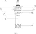
- Figure 1 -
- Brake Adjustment Mechanism
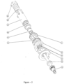
- Figure 2 -
- Demounting view of Brake Adjustment Mechanism
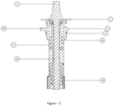
- Figure 3 -
- Cross-section view of Brake Adjustment Mechanism
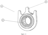
- Figure 4 -
- Perspective view of Short Body
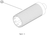
- Figure 5 -
- Perspective view of Brake Adjustment spindle
- Parts constituting Brake Adjustment Mechanism disclosed under the invention are shown in figures with the numbers given below.
- 1-
- Set Spindle
- 2-
- Flange
- 3-
- Cover
- 5-
- Short Body
- 6-
- Pin ball bearing
- 7-
- Ball bearing housing
- 8-
- Fixed spring
- 9-
- Inner Body
- 10-
- Single ball
- 11-
- Long Body
- 12-
- Steel Press Spring
- 13-
- Eccentric Flap
- 14-
- Brake Adjustment Spindle
- 15-
- Brake Adjustment Mechanism
- 16-
- Short Body Clamps
- Brake adjustment mechanism consists of following parts.
- (
Figure 2 ) Set spindle (1) of bracket structure providing manual adjustment is located at the very end in a manner it remains outside when brake adjustment mechanism is seated onto calliper. The part sitting onto calliper is cover (3) part. Flange (2) is placed to enable movement between set spindle (1) and cover (3) and sliding. - Inner part of short body (5) consists of pin ball bearings (6) which is one of main component of the invention providing one way rotation and locking movement in case of opposite movement. Outer part of short body (5) consists of fixed spring (8) surrounding body.
- Short body (5) is placed on ball bearing (7) and single ball in order to enable easy movement to the side where short body (5) can move. Inner body (9) is located inside ball bearing housing (7) of short body (5) and partially long body (11) and transforms motion. Steel press spring (12) is placed inside long body (11).
- Eccentric flaps (13) are located in the section in bottom inside adjustment spindle of long body (11).
- Working principle of brake adjustment mechanism is as follows. Cover (3) part of the mechanism seated into brake adjustment spindle (14) in a manner set spindle (1) remains outside seats onto calliper. Eccentric flaps (13) located in lower part of brake adjustment mechanism seat into cavities inside the brake adjustment spindle (14) and thus any rotation movement provided in mechanism is transferred to brake adjustment spindle (14)
- Brake adjustment spindle (14) is moved forward or backward by means of rotation of set spindle (1) around its axis, and positions of pads on other end are adjusted.
- In case of wearing of pads, in turn, brake adjustment spindle (14) is moved forward in the distance corresponding to thickness of wearing. This motion is provided by means of rotation of short body clamps (16) on the short body (5) by rotating arm located inside calliper (during braking). Since pin ball bearings (6) located on inner surface of short body (5) do not allow rotation in this direction, short body (5) remains fixed and brake adjustment mechanism rotates as a whole.
- In cases where there is no wearing, this rotation movement does not occur as there is no distance that brake adjustment spindle (14) may move while in case of wearing brake adjustment spindle (14) rotates around its axis in the distance corresponding to wearing.
- After braking, brake adjustment spindle (14) current position should be protected and therefore rotation movement of rotating arm in opposite direction in calliper should be absorbed. Since opposite movement of rotating arm is in direction where pin ball bearings (6) on inner surface of short body (5) can rotate, pins make a free rotation movement and provides rotation of short body (5) independent from mechanism and thus brake adjustment spindle (14) and provides protection of brake adjustment spindle.
- Where brake adjustment mechanism rotates as a whole, rotation movement transferred to short body (5) is transmitted to long body (11) where eccentric flaps (13) are by means of inner body (9). Single balls (10) are located in the joining point between inner body (9) and long body (13) in order to enable problem-free and high efficient transmission of motion under high pressure.
- The rate of part used for uniform rotation of mechanism in the prior art is reduced to one to fourth and negative results arising from high number of part are prevented.
- Also rotation of short body (5) on one single axis is provided by means of pin ball bearings (6) placed on inner wall, locking with inner body (9) developed in harmony with such bearings and rotation separate from mechanism is provided. Fixing members of clamp structure used for locking operation and conical clutching in prior art may get worn under high torque by time and need replacement every six months on average. Pin ball bearings (6) and inner body (9) solve wearing problem and thus life of brake adjustment mechanism is made longer and easy to use and cost advantage is provided.
Claims (1)
- A brake adjustment mechanism (15) used for adjustment of the pre-use distance between brake pads and pressing onto brake disk during braking and thus converting kinetic energy into heat energy, providing slowing down and stop of the vehicle and automatically adjusting distance differences arising from wearing in the brake pads during the period of use, having cover (3) part seated into brake adjustment spindle (14) in a manner set spindle (1) remains outside seats onto calliper, eccentric flaps (13) located in lower part of said brake adjustment mechanism (15) seat into cavities inside the brake adjustment spindle (14) and thus any rotation movement provided in mechanism is transferred to brake adjustment spindle (14) characterized by; comprising
pin ball bearings (6) located on inner surface of short body (5) which do not allow rotation in as same direction as rotation direction of set spindle (1) around its axis and allow short body (5) remains fixed thus brake adjustment mechanism rotates as a whole during braking while allow rotation of short body (5) independent from mechanism thus brake adjustment spindle (14) and allow protection of position of brake adjustment spindle after braking.
Applications Claiming Priority (2)
| Application Number | Priority Date | Filing Date | Title |
|---|---|---|---|
| TR201809647 | 2018-07-06 | ||
| PCT/TR2019/050531 WO2020009679A2 (en) | 2018-07-06 | 2019-07-05 | Automatic interbrake pads distance adjuster |
Publications (4)
| Publication Number | Publication Date |
|---|---|
| EP3775598A2 EP3775598A2 (en) | 2021-02-17 |
| EP3775598A4 EP3775598A4 (en) | 2021-12-29 |
| EP3775598B1 true EP3775598B1 (en) | 2024-08-21 |
| EP3775598C0 EP3775598C0 (en) | 2024-08-21 |
Family
ID=69061014
Family Applications (1)
| Application Number | Title | Priority Date | Filing Date |
|---|---|---|---|
| EP19830251.5A Active EP3775598B1 (en) | 2018-07-06 | 2019-07-05 | Automatic interbrake pads distance adjuster |
Country Status (2)
| Country | Link |
|---|---|
| EP (1) | EP3775598B1 (en) |
| WO (1) | WO2020009679A2 (en) |
Families Citing this family (1)
| Publication number | Priority date | Publication date | Assignee | Title |
|---|---|---|---|---|
| EP4638439A1 (en) | 2022-12-21 | 2025-10-29 | Merck Patent GmbH | Novel materials for organic electroluminescent devices |
Family Cites Families (3)
| Publication number | Priority date | Publication date | Assignee | Title |
|---|---|---|---|---|
| KR101217096B1 (en) * | 2012-09-17 | 2012-12-31 | 세신전기(주) | Brake apparatus for adjustable brake pad gap |
| DE102014017438A1 (en) * | 2014-11-25 | 2016-05-25 | Wabco Europe Bvba | Disc brake. especially for commercial vehicles |
| CN105485224B (en) * | 2016-01-14 | 2017-08-01 | 枣庄泰德机械有限公司 | Brake clearance automatic mechanism assembly |
-
2019
- 2019-07-05 EP EP19830251.5A patent/EP3775598B1/en active Active
- 2019-07-05 WO PCT/TR2019/050531 patent/WO2020009679A2/en not_active Ceased
Also Published As
| Publication number | Publication date |
|---|---|
| EP3775598A4 (en) | 2021-12-29 |
| WO2020009679A3 (en) | 2020-04-09 |
| EP3775598A2 (en) | 2021-02-17 |
| WO2020009679A2 (en) | 2020-01-09 |
| WO2020009679A9 (en) | 2020-02-20 |
| EP3775598C0 (en) | 2024-08-21 |
Similar Documents
| Publication | Publication Date | Title |
|---|---|---|
| US3682277A (en) | Disc brakes and mounting structure therefor | |
| JP5513914B2 (en) | Disc brake device with electric parking mechanism | |
| JP6543149B2 (en) | Brake device | |
| CN106104058B (en) | Actuator with irreversible screw-and-nut system, drum brake and brake apparatus equipped with the actuator | |
| CN108443365B (en) | A kind of vehicle braking mechanism based on screw-driven | |
| JP5368528B2 (en) | Mechanical disc brake for stationary | |
| US4256206A (en) | Disc brake | |
| US10161466B2 (en) | Brake device | |
| AU2009231490A1 (en) | Protective system for machine tools | |
| CZ285089B6 (en) | Driving device for disk brakes | |
| JP2001522441A (en) | Brake lining wear regulator assembly | |
| US3261430A (en) | Spot type disc brakes | |
| JPH0366538B2 (en) | ||
| EP3564553B1 (en) | An adjuster mechanism | |
| US3295636A (en) | Brake mechanism | |
| RU2310109C2 (en) | Method of mounting brake caliper | |
| JPS5928783B2 (en) | Vehicle brake actuator | |
| EP3775598B1 (en) | Automatic interbrake pads distance adjuster | |
| JPH06185549A (en) | Mechanical actuated disc brake | |
| EP3957876B1 (en) | Brake pad arrangement | |
| US3326329A (en) | Actuating and self-adjusting mechanism for disc brakes | |
| CN107923461B (en) | Adjustment device for disc brakes | |
| US3487895A (en) | Axially movable caliper disc brake | |
| JP2017172731A (en) | Braking device | |
| JPH0517410B2 (en) |
Legal Events
| Date | Code | Title | Description |
|---|---|---|---|
| STAA | Information on the status of an ep patent application or granted ep patent |
Free format text: STATUS: THE INTERNATIONAL PUBLICATION HAS BEEN MADE |
|
| PUAI | Public reference made under article 153(3) epc to a published international application that has entered the european phase |
Free format text: ORIGINAL CODE: 0009012 |
|
| STAA | Information on the status of an ep patent application or granted ep patent |
Free format text: STATUS: REQUEST FOR EXAMINATION WAS MADE |
|
| 17P | Request for examination filed |
Effective date: 20200928 |
|
| AK | Designated contracting states |
Kind code of ref document: A2 Designated state(s): AL AT BE BG CH CY CZ DE DK EE ES FI FR GB GR HR HU IE IS IT LI LT LU LV MC MK MT NL NO PL PT RO RS SE SI SK SM TR |
|
| AX | Request for extension of the european patent |
Extension state: BA ME |
|
| DAV | Request for validation of the european patent (deleted) | ||
| DAX | Request for extension of the european patent (deleted) | ||
| A4 | Supplementary search report drawn up and despatched |
Effective date: 20211125 |
|
| RIC1 | Information provided on ipc code assigned before grant |
Ipc: F16D 65/00 20060101AFI20211119BHEP |
|
| GRAP | Despatch of communication of intention to grant a patent |
Free format text: ORIGINAL CODE: EPIDOSNIGR1 |
|
| STAA | Information on the status of an ep patent application or granted ep patent |
Free format text: STATUS: GRANT OF PATENT IS INTENDED |
|
| INTG | Intention to grant announced |
Effective date: 20240429 |
|
| GRAJ | Information related to disapproval of communication of intention to grant by the applicant or resumption of examination proceedings by the epo deleted |
Free format text: ORIGINAL CODE: EPIDOSDIGR1 |
|
| GRAP | Despatch of communication of intention to grant a patent |
Free format text: ORIGINAL CODE: EPIDOSNIGR1 |
|
| GRAS | Grant fee paid |
Free format text: ORIGINAL CODE: EPIDOSNIGR3 |
|
| GRAA | (expected) grant |
Free format text: ORIGINAL CODE: 0009210 |
|
| STAA | Information on the status of an ep patent application or granted ep patent |
Free format text: STATUS: THE PATENT HAS BEEN GRANTED |
|
| INTG | Intention to grant announced |
Effective date: 20240625 |
|
| AK | Designated contracting states |
Kind code of ref document: B1 Designated state(s): AL AT BE BG CH CY CZ DE DK EE ES FI FR GB GR HR HU IE IS IT LI LT LU LV MC MK MT NL NO PL PT RO RS SE SI SK SM TR |
|
| REG | Reference to a national code |
Ref country code: GB Ref legal event code: FG4D |
|
| REG | Reference to a national code |
Ref country code: CH Ref legal event code: EP |
|
| REG | Reference to a national code |
Ref country code: DE Ref legal event code: R096 Ref document number: 602019057552 Country of ref document: DE |
|
| REG | Reference to a national code |
Ref country code: IE Ref legal event code: FG4D |
|
| U01 | Request for unitary effect filed |
Effective date: 20240821 |
|
| U07 | Unitary effect registered |
Designated state(s): AT BE BG DE DK EE FI FR IT LT LU LV MT NL PT RO SE SI Effective date: 20240902 |
|
| PG25 | Lapsed in a contracting state [announced via postgrant information from national office to epo] |
Ref country code: NO Free format text: LAPSE BECAUSE OF FAILURE TO SUBMIT A TRANSLATION OF THE DESCRIPTION OR TO PAY THE FEE WITHIN THE PRESCRIBED TIME-LIMIT Effective date: 20241121 |
|
| PG25 | Lapsed in a contracting state [announced via postgrant information from national office to epo] |
Ref country code: PL Free format text: LAPSE BECAUSE OF FAILURE TO SUBMIT A TRANSLATION OF THE DESCRIPTION OR TO PAY THE FEE WITHIN THE PRESCRIBED TIME-LIMIT Effective date: 20240821 Ref country code: GR Free format text: LAPSE BECAUSE OF FAILURE TO SUBMIT A TRANSLATION OF THE DESCRIPTION OR TO PAY THE FEE WITHIN THE PRESCRIBED TIME-LIMIT Effective date: 20241122 |
|
| PG25 | Lapsed in a contracting state [announced via postgrant information from national office to epo] |
Ref country code: IS Free format text: LAPSE BECAUSE OF FAILURE TO SUBMIT A TRANSLATION OF THE DESCRIPTION OR TO PAY THE FEE WITHIN THE PRESCRIBED TIME-LIMIT Effective date: 20241221 |
|
| PG25 | Lapsed in a contracting state [announced via postgrant information from national office to epo] |
Ref country code: HR Free format text: LAPSE BECAUSE OF FAILURE TO SUBMIT A TRANSLATION OF THE DESCRIPTION OR TO PAY THE FEE WITHIN THE PRESCRIBED TIME-LIMIT Effective date: 20240821 |
|
| PG25 | Lapsed in a contracting state [announced via postgrant information from national office to epo] |
Ref country code: RS Free format text: LAPSE BECAUSE OF FAILURE TO SUBMIT A TRANSLATION OF THE DESCRIPTION OR TO PAY THE FEE WITHIN THE PRESCRIBED TIME-LIMIT Effective date: 20241121 Ref country code: ES Free format text: LAPSE BECAUSE OF FAILURE TO SUBMIT A TRANSLATION OF THE DESCRIPTION OR TO PAY THE FEE WITHIN THE PRESCRIBED TIME-LIMIT Effective date: 20240821 |
|
| PG25 | Lapsed in a contracting state [announced via postgrant information from national office to epo] |
Ref country code: RS Free format text: LAPSE BECAUSE OF FAILURE TO SUBMIT A TRANSLATION OF THE DESCRIPTION OR TO PAY THE FEE WITHIN THE PRESCRIBED TIME-LIMIT Effective date: 20241121 Ref country code: PL Free format text: LAPSE BECAUSE OF FAILURE TO SUBMIT A TRANSLATION OF THE DESCRIPTION OR TO PAY THE FEE WITHIN THE PRESCRIBED TIME-LIMIT Effective date: 20240821 Ref country code: NO Free format text: LAPSE BECAUSE OF FAILURE TO SUBMIT A TRANSLATION OF THE DESCRIPTION OR TO PAY THE FEE WITHIN THE PRESCRIBED TIME-LIMIT Effective date: 20241121 Ref country code: IS Free format text: LAPSE BECAUSE OF FAILURE TO SUBMIT A TRANSLATION OF THE DESCRIPTION OR TO PAY THE FEE WITHIN THE PRESCRIBED TIME-LIMIT Effective date: 20241221 Ref country code: HR Free format text: LAPSE BECAUSE OF FAILURE TO SUBMIT A TRANSLATION OF THE DESCRIPTION OR TO PAY THE FEE WITHIN THE PRESCRIBED TIME-LIMIT Effective date: 20240821 Ref country code: GR Free format text: LAPSE BECAUSE OF FAILURE TO SUBMIT A TRANSLATION OF THE DESCRIPTION OR TO PAY THE FEE WITHIN THE PRESCRIBED TIME-LIMIT Effective date: 20241122 Ref country code: ES Free format text: LAPSE BECAUSE OF FAILURE TO SUBMIT A TRANSLATION OF THE DESCRIPTION OR TO PAY THE FEE WITHIN THE PRESCRIBED TIME-LIMIT Effective date: 20240821 |
|
| PG25 | Lapsed in a contracting state [announced via postgrant information from national office to epo] |
Ref country code: SM Free format text: LAPSE BECAUSE OF FAILURE TO SUBMIT A TRANSLATION OF THE DESCRIPTION OR TO PAY THE FEE WITHIN THE PRESCRIBED TIME-LIMIT Effective date: 20240821 |
|
| PG25 | Lapsed in a contracting state [announced via postgrant information from national office to epo] |
Ref country code: CZ Free format text: LAPSE BECAUSE OF FAILURE TO SUBMIT A TRANSLATION OF THE DESCRIPTION OR TO PAY THE FEE WITHIN THE PRESCRIBED TIME-LIMIT Effective date: 20240821 |
|
| PG25 | Lapsed in a contracting state [announced via postgrant information from national office to epo] |
Ref country code: SK Free format text: LAPSE BECAUSE OF FAILURE TO SUBMIT A TRANSLATION OF THE DESCRIPTION OR TO PAY THE FEE WITHIN THE PRESCRIBED TIME-LIMIT Effective date: 20240821 |
|
| U1N | Appointed representative for the unitary patent procedure changed after the registration of the unitary effect |
Representative=s name: METIDA; LT |
|
| PLBE | No opposition filed within time limit |
Free format text: ORIGINAL CODE: 0009261 |
|
| STAA | Information on the status of an ep patent application or granted ep patent |
Free format text: STATUS: NO OPPOSITION FILED WITHIN TIME LIMIT |
|
| U20 | Renewal fee for the european patent with unitary effect paid |
Year of fee payment: 7 Effective date: 20250602 |
|
| 26N | No opposition filed |
Effective date: 20250522 |
|
| REG | Reference to a national code |
Ref country code: CH Ref legal event code: H13 Free format text: ST27 STATUS EVENT CODE: U-0-0-H10-H13 (AS PROVIDED BY THE NATIONAL OFFICE) Effective date: 20260224 |
|
| GBPC | Gb: european patent ceased through non-payment of renewal fee |
Effective date: 20250705 |
|
| PG25 | Lapsed in a contracting state [announced via postgrant information from national office to epo] |
Ref country code: GB Free format text: LAPSE BECAUSE OF NON-PAYMENT OF DUE FEES Effective date: 20250705 |
|
| PG25 | Lapsed in a contracting state [announced via postgrant information from national office to epo] |
Ref country code: CH Free format text: LAPSE BECAUSE OF NON-PAYMENT OF DUE FEES Effective date: 20250731 |