EP3775506B1 - Kraftwerksanlage mit erdgasregasifizierung - Google Patents
Kraftwerksanlage mit erdgasregasifizierung Download PDFInfo
- Publication number
- EP3775506B1 EP3775506B1 EP19727887.2A EP19727887A EP3775506B1 EP 3775506 B1 EP3775506 B1 EP 3775506B1 EP 19727887 A EP19727887 A EP 19727887A EP 3775506 B1 EP3775506 B1 EP 3775506B1
- Authority
- EP
- European Patent Office
- Prior art keywords
- natural gas
- heat exchanger
- power station
- heat
- station plant
- Prior art date
- Legal status (The legal status is an assumption and is not a legal conclusion. Google has not performed a legal analysis and makes no representation as to the accuracy of the status listed.)
- Active
Links
Images

Classifications
-
- F—MECHANICAL ENGINEERING; LIGHTING; HEATING; WEAPONS; BLASTING
- F02—COMBUSTION ENGINES; HOT-GAS OR COMBUSTION-PRODUCT ENGINE PLANTS
- F02C—GAS-TURBINE PLANTS; AIR INTAKES FOR JET-PROPULSION PLANTS; CONTROLLING FUEL SUPPLY IN AIR-BREATHING JET-PROPULSION PLANTS
- F02C7/00—Features, components parts, details or accessories, not provided for in, or of interest apart form groups F02C1/00 - F02C6/00; Air intakes for jet-propulsion plants
- F02C7/22—Fuel supply systems
- F02C7/224—Heating fuel before feeding to the burner
-
- F—MECHANICAL ENGINEERING; LIGHTING; HEATING; WEAPONS; BLASTING
- F01—MACHINES OR ENGINES IN GENERAL; ENGINE PLANTS IN GENERAL; STEAM ENGINES
- F01K—STEAM ENGINE PLANTS; STEAM ACCUMULATORS; ENGINE PLANTS NOT OTHERWISE PROVIDED FOR; ENGINES USING SPECIAL WORKING FLUIDS OR CYCLES
- F01K25/00—Plants or engines characterised by use of special working fluids, not otherwise provided for; Plants operating in closed cycles and not otherwise provided for
- F01K25/08—Plants or engines characterised by use of special working fluids, not otherwise provided for; Plants operating in closed cycles and not otherwise provided for using special vapours
- F01K25/10—Plants or engines characterised by use of special working fluids, not otherwise provided for; Plants operating in closed cycles and not otherwise provided for using special vapours the vapours being cold, e.g. ammonia, carbon dioxide, ether
-
- F—MECHANICAL ENGINEERING; LIGHTING; HEATING; WEAPONS; BLASTING
- F01—MACHINES OR ENGINES IN GENERAL; ENGINE PLANTS IN GENERAL; STEAM ENGINES
- F01K—STEAM ENGINE PLANTS; STEAM ACCUMULATORS; ENGINE PLANTS NOT OTHERWISE PROVIDED FOR; ENGINES USING SPECIAL WORKING FLUIDS OR CYCLES
- F01K9/00—Plants characterised by condensers arranged or modified to co-operate with the engines
- F01K9/003—Plants characterised by condensers arranged or modified to co-operate with the engines condenser cooling circuits
-
- F—MECHANICAL ENGINEERING; LIGHTING; HEATING; WEAPONS; BLASTING
- F02—COMBUSTION ENGINES; HOT-GAS OR COMBUSTION-PRODUCT ENGINE PLANTS
- F02C—GAS-TURBINE PLANTS; AIR INTAKES FOR JET-PROPULSION PLANTS; CONTROLLING FUEL SUPPLY IN AIR-BREATHING JET-PROPULSION PLANTS
- F02C3/00—Gas-turbine plants characterised by the use of combustion products as the working fluid
- F02C3/04—Gas-turbine plants characterised by the use of combustion products as the working fluid having a turbine driving a compressor
-
- F—MECHANICAL ENGINEERING; LIGHTING; HEATING; WEAPONS; BLASTING
- F22—STEAM GENERATION
- F22B—METHODS OF STEAM GENERATION; STEAM BOILERS
- F22B1/00—Methods of steam generation characterised by form of heating method
- F22B1/02—Methods of steam generation characterised by form of heating method by exploitation of the heat content of hot heat carriers
- F22B1/18—Methods of steam generation characterised by form of heating method by exploitation of the heat content of hot heat carriers the heat carrier being a hot gas, e.g. waste gas such as exhaust gas of internal-combustion engines
- F22B1/1807—Methods of steam generation characterised by form of heating method by exploitation of the heat content of hot heat carriers the heat carrier being a hot gas, e.g. waste gas such as exhaust gas of internal-combustion engines using the exhaust gases of combustion engines
- F22B1/1815—Methods of steam generation characterised by form of heating method by exploitation of the heat content of hot heat carriers the heat carrier being a hot gas, e.g. waste gas such as exhaust gas of internal-combustion engines using the exhaust gases of combustion engines using the exhaust gases of gas-turbines
-
- F—MECHANICAL ENGINEERING; LIGHTING; HEATING; WEAPONS; BLASTING
- F05—INDEXING SCHEMES RELATING TO ENGINES OR PUMPS IN VARIOUS SUBCLASSES OF CLASSES F01-F04
- F05D—INDEXING SCHEME FOR ASPECTS RELATING TO NON-POSITIVE-DISPLACEMENT MACHINES OR ENGINES, GAS-TURBINES OR JET-PROPULSION PLANTS
- F05D2220/00—Application
- F05D2220/30—Application in turbines
- F05D2220/32—Application in turbines in gas turbines
-
- F—MECHANICAL ENGINEERING; LIGHTING; HEATING; WEAPONS; BLASTING
- F05—INDEXING SCHEMES RELATING TO ENGINES OR PUMPS IN VARIOUS SUBCLASSES OF CLASSES F01-F04
- F05D—INDEXING SCHEME FOR ASPECTS RELATING TO NON-POSITIVE-DISPLACEMENT MACHINES OR ENGINES, GAS-TURBINES OR JET-PROPULSION PLANTS
- F05D2260/00—Function
- F05D2260/20—Heat transfer, e.g. cooling
Definitions
- the invention relates to a power plant and a method for operating it.
- this involves the energetically and economically optimal evaporation of liquid natural gas when directly coupled to a gas and steam turbine system or to a gas-fired power plant.
- ambient heat air / seawater
- chemical heat Alternatively, concepts were developed that aimed to use the low-temperature cold for energy via cascading Organic Rankine cycles.
- a further object of the invention is to specify a corresponding method for operating such a power plant.
- the invention solves the problem related to a power plant by proposing a power plant with a gas turbine, which includes a compressor, a combustion chamber and a turbine, with a natural gas line for transporting liquid and gaseous natural gas to the gas turbine, a line connected to the natural gas line Compressor for increasing a liquid natural gas pressure and an expander which is also connected to the natural gas line, further comprising and arranged between the compressor and the expander a first heat exchanger for the evaporation of liquid natural gas and a second heat exchanger for the further heating of the regasified natural gas, the power plant comprising a heat recovery steam generator and wherein the second heat exchanger is coupled to a condensate preheater in the heat recovery steam generator.
- a third heat exchanger is connected downstream of the expander in the natural gas line.
- the second heat exchanger there is also the possibility of using the second heat exchanger to heat the natural gas to such an extent that it can be fed to combustion after expansion in a correspondingly preheated manner, so that the use of a third heat exchanger can be dispensed with for cost reasons.
- the technically better variant is the one with further heating by the third heat exchanger downstream of the expansion.
- the first heat exchanger is connected to an intake air line of the gas turbine via a heat transfer medium circuit.
- the first heat exchanger is connected to a cooling system of the power plant via a heat transfer medium circuit.
- the heat from the gas turbine intake air or from the cooling system can be used in parallel or in series.
- the heat transfer medium circuit is a water-glycol circuit.
- a hot condensate extraction point for the second heat exchanger is located downstream of a high-pressure feedwater pump in the direction of flow of the feedwater at a correspondingly high pressure, in order to avoid an undesirable pressure from a safety point of view To prevent the natural gas from entering the water-steam cycle in the event of a leak.
- a hot condensate extraction point for the second heat exchanger is downstream of a condensate recirculation pump in the flow direction of the condensate and the second heat exchanger is a double-walled safety heat exchanger as a measure to prevent unwanted natural gas transfer.
- This alternative arrangement of the hot condensate extraction point has advantages in terms of efficiency.
- the third heat exchanger it is advantageous if it is coupled to a feedwater system of the heat recovery steam generator. After the preheated natural gas has been expanded via the expander to the gas pressure level required for gas turbine operation with power output, a gas temperature of approx. 40 - 70°C is reached. In order to achieve the maximum permissible gas turbine fuel temperature for performance reasons, the third heat exchanger is arranged in the natural gas line between the expander and the gas turbine. This third heat exchanger draws its heat from the medium-pressure or high-pressure feed water from the heat recovery steam generator.
- This approach can also be used in gas turbine power plants, even if no heat recovery steam generator is provided in such a power plant configuration.
- the necessary heat transfer surfaces for the integration of exhaust gas heat into the second and third heat exchangers can be arranged, for example, in an internal chimney bypass of the gas turbine, in which hot exhaust gas is routed through a separate channel with heating surfaces and cooled and mixed back into the main exhaust gas mass flow.
- the object directed to a method is achieved by a method for operating a power plant with liquefied natural gas vaporization, in which liquefied natural gas at least 150 bar is brought, with heat from a gas turbine intake air and/or from a cooling system of the power plant being used to gasify liquid natural gas and with natural gas being further heated in heat exchange with hot condensate from a condensate preheater of a heat recovery steam generator in a further step.
- hot exhaust gas can be routed via a duct with heating surfaces for evaporation and heating of liquefied natural gas and, once cooled, mixed back into the main exhaust gas mass flow.
- the figure 1 shows schematically and by way of example a power plant 1 designed as a gas and steam turbine plant according to the invention.
- the power plant 1 comprises a gas turbine 2 with a compressor 3, a combustion chamber 4 and a turbine 5.
- figure 1 shows a natural gas line 6 branching off from a natural gas tank 22 for the transport of liquid and gaseous natural gas, in which a natural gas compressor 7 for increasing a liquid natural gas pressure and an expander 8 are connected.
- a first heat exchanger 9 for the evaporation of liquid natural gas and a second heat exchanger 10 for the further heating of the regasified natural gas are connected between the natural gas compressor 7 and the expander 8 .
- a third heat exchanger 11 is also arranged in the natural gas line 6 behind the expander 8 .
- the first heat exchanger 9 is connected via a heat transfer medium circuit 12 and a fourth heat exchanger 28 in an intake air line 13 of the gas turbine 2 and via a fifth heat exchanger 29 in a cooling system of the power plant 1 .
- fourth and fifth heat exchangers 28,29 are arranged in series. However, a parallel arrangement is also conceivable.
- the heat transfer medium circuit 12 is typically a water-glycol circuit.
- the power plant 1 is a gas and steam turbine plant, as in the figure 1 shown, then it further comprises a heat recovery steam generator 14, wherein the second heat exchanger 10 is coupled to a condensate preheater 15 in the heat recovery steam generator 14.
- figure 1 shows both hot condensate extraction options for the second heat exchanger 10.
- a hot condensate extraction point 16 is located behind a high-pressure feedwater pump 17.
- the hot condensate extraction point 16 is located behind a condensate recirculation pump 18.
- the second heat exchanger 10 should be designed as a double-walled safety heat exchanger be.
- figure 1 finally shows that the third heat exchanger 11 is coupled to a feed water system 19 of the heat recovery steam generator 14 .
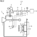
- figure 2 shows a gas turbine system 25 with an exhaust chimney 26 and a chimney bypass 20 on the exhaust chimney 26.
- the arrangement of the components for the regasification of the natural gas is different from the system in FIG figure 1 unchanged.
- the heat for the second and third heat exchangers 10, 11 is obtained here from the gas turbine exhaust gas via corresponding heat exchanger surfaces 21 in the stack bypass 20 of the exhaust stack 26.
- part of the exhaust gas is routed via the chimney bypass 20 and, after the heat has been released to the corresponding heat transfer surfaces 21 , is mixed back into the main exhaust gas stream 27 .
Landscapes
- Engineering & Computer Science (AREA)
- Chemical & Material Sciences (AREA)
- Combustion & Propulsion (AREA)
- Mechanical Engineering (AREA)
- General Engineering & Computer Science (AREA)
- Life Sciences & Earth Sciences (AREA)
- Sustainable Development (AREA)
- Sustainable Energy (AREA)
- Physics & Mathematics (AREA)
- Thermal Sciences (AREA)
- Engine Equipment That Uses Special Cycles (AREA)
Description
- Die Erfindung betrifft eine Kraftwerksanlage sowie ein Verfahren zu deren Betrieb. Dabei geht es insbesondere um die energetisch und wirtschaftlich optimale Verdampfung von flüssigem Erdgas bei einer direkten Kopplung an eine Gas- und Dampfturbinenanlage oder an ein Gaskraftwerk.
- Üblicherweise wird flüssiges Erdgas (LNG = liquid natural gas (T=-162°C)) mit Umgebungswärme (Luft / Meerwasser) oder chemischer Wärme verdampft. Alternativ wurden Konzepte entwickelt, die über kaskadierende Organic-Rankine-Kreisläufe eine energetische Nutzung der Tieftemperaturkälte zum Ziel hatten.
- Das Dokument
US 2007/101732 A1 offenbart eine Kraftwerksanlage nach dem Stand der Technik. - Aufgabe der Erfindung ist es, eine Kraftwerksanlage bereitzustellen, die eine verbesserte Leistung bzw. einen verbesserten Wirkungsgrad ermöglicht und die zugleich möglichst einfach und kostengünstig herzustellen ist. Eine weitere Aufgabe der Erfindung ist es, ein entsprechendes Verfahren zum Betrieb einer solchen Kraftwerksanlage anzugeben.
- Die Erfindung löst die auf eine Kraftwerksanlage gerichtete Aufgabe, indem sie eine Kraftwerksanlage vorschlägt, mit einer Gasturbine, die einen Verdichter, eine Brennkammer und eine Turbine umfasst, mit einer Erdgasleitung für den Transport von flüssigem und gasförmigem Erdgas zur Gasturbine, einem in die Erdgasleitung geschalteten Verdichter zur Erhöhung eines Flüssigerdgas-Drucks und einem ebenfalls in die Erdgasleitung geschalteten Expander, weiter umfassend und zwischen Verdichter und Expander angeordnet einen ersten Wärmeübertrager für die Verdampfung flüssigen Erdgases und einen zweiten Wärmeübertrager für die weitere Erwärmung des regasifizierten Erdgases, wobei die Kraftwerksanlage einen Abhitzedampferzeuger umfasst und wobei der zweite Wärmeübertrager mit einem Kondensatvorwärmer im Abhitzedampferzeuger gekoppelt ist.
- Durch Kopplung der Flüssigerdgas-Verdampfung an einen nachgeschalten Expander wird es möglich, eine maximale Nutzung der Tieftemperaturkälte zur Stromerzeugung mit höchsten Wirkungsgraden zu erreichen. Durch eine Kopplung des zweiten Wärmeübertragers mit einem Kondensatvorwärmer, d.h. mit der letzten Heizfläche im Abhitzedampferzeuger, wird das bereits verdampfte Erdgas weiter auf ca. 130 - 170°C erwärmt.
- Besonders vorteilhaft für den Wirkungsgrad der Kraftwerksanlage ist es, wenn ein dritter Wärmeübertrager in der Erdgasleitung dem Expander nachgeschaltet ist. Es besteht prinzipiell zwar auch die Möglichkeit, mit dem zweiten Wärmeübertrager das Erdgas soweit aufzuheizen, dass es auch nach der Expansion entsprechend vorgewärmt der Verbrennung zugeführt werden kann, so dass aus Kostengründen auf den Einsatz eines dritten Wärmeübertragers verzichtet werden kann. Die technisch bessere Variante ist aber diejenige mit einer der Expansion nachgeschalteten weiteren Erwärmung durch den dritten Wärmeübertrager.
- In einer vorteilhaften Ausführungsform der Erfindung ist der erste Wärmeübertrager über einen Wärmeträgermedium-Kreislauf in eine Ansaugluftleitung der Gasturbine geschaltet.
- In einer weiteren vorteilhaften Ausführungsform ist der erste Wärmeübertrager über einen Wärmeträgermedium-Kreislauf in ein Kühlsystem der Kraftwerksanlage geschaltet. Dabei kann die Wärme aus der Gasturbinen-Ansaugluft bzw. aus dem Kühlsystem parallel oder in Reihe geschaltet verwendet werden.
- Dabei ist es im Hinblick auf Einfrieren und Wärmeleitfähigkeit des Wärmeträgers zweckmäßig, wenn der Wärmeträgermedium-Kreislauf ein Wasser-Glykol-Kreislauf ist.
- Es ist zweckmäßig, wenn ein Heißkondensatentnahmepunkt für den zweiten Wärmeübertrager in Strömungsrichtung des Speisewassers hinter einer Hochdruck-Speisewasserpumpe bei entsprechend hohem Druck liegt, um einen aus Sicherheitsaspekten unerwünschten Übertritt des Erdgases in den Wasser-Dampf-Kreislauf im Fall einer Leckage zu verhindern.
- Alternativ ist es vorteilhaft, wenn ein Heißkondensatentnahmepunkt für den zweiten Wärmeübertrager in Strömungsrichtung des Kondensats hinter einer Kondensatrezirkulationspumpe liegt und der zweite Wärmeübertrager ein doppelwandiger Sicherheitswärmeübertrager ist, als Maßnahme zur Verhinderung eines unerwünschten Erdgasübertritts. Diese alternative Anordnung des Heißkondensatentnahmepunkts hat Vorteile im Wirkungsgrad.
- Bezüglich des dritten Wärmeübertragers ist es vorteilhaft, wenn er mit einem Speisewassersystem des Abhitzedampferzeugers gekoppelt ist. Nachdem das vorgewärmte Erdgas über den Expander auf das für den Gasturbinen-Betrieb notwendige Gasdruckniveau unter Leistungsabgabe entspannt wurde, stellt sich eine Gastemperatur von ca. 40 - 70°C ein. Um aus Performancegründen die maximal zulässige Gasturbinen-Brennstofftemperatur zu erreichen, wird der dritte Wärmeübertrager zwischen Expander und Gasturbine in der Erdgasleitung angeordnet. Dieser dritte Wärmeübertrager bezieht seine Wärme aus dem Mitteldruck- oder Hochdruck-Speisewasser des Abhitzedampferzeugers.
- Dieser Ansatz kann auch bei Gasturbinenkraftwerken zum Einsatz kommen, auch wenn in einer solchen Kraftwerkskonfiguration kein Abhitzedampferzeuger vorgesehen ist. Die notwendigen Wärmeübertragerflächen zur Integration von Abgaswärme in den zweiten und dritten Wärmeübertrager können z.B. in einem internen Kaminbypass der Gasturbine angeordnet werden, bei dem heißes Abgas über einen separaten Kanal mit Heizflächen geführt und abgekühlt und dem Hauptabgasmassenstrom wieder zugemischt wird.
- Die auf ein Verfahren gerichtete Aufgabe wird gelöst durch ein Verfahren zum Betreiben einer Kraftwerksanlage mit Flüssigerdgas-Verdampfung, bei dem flüssiges Erdgas auf mindestens 150 bar gebracht wird, wobei Wärme aus einer Gasturbinenansaugluft und/oder aus einem Kühlsystem der Kraftwerksanlage verwendet wird, um flüssiges Erdgas zu vergasen und wobei in einem weiteren Schritt Erdgas im Wärmetausch mit Heißkondensat aus einem Kondensatvorwärmer eines Abhitzedampferzeugers weiter erwärmt wird.
- Dabei ist es zweckmäßig, wenn das weiter erwärmte Erdgas über einen Expander auf ein für einen Gasturbinen-Betrieb notwendiges Gasdruckniveau unter Leistungsabgabe entspannt wird.
- Weiter ist es vorteilhaft, wenn das entspannte Erdgas im Wärmetausch mit Speisewasser weiter erwärmt wird.
- Bei Kraftwerkanlagen mit Gasturbine aber ohne Wasser-Dampf-Kreislauf kann heißes Abgas über einen Kanal mit Heizflächen für eine Verdampfung und Erwärmung von Flüssigerdgas geführt und abgekühlt dem Hauptabgasmassenstrom wieder zugemischt werden.
- Durch die Kopplung der Wiederverdampfung an einen nachgeschalteten Expander und eine damit verbundene optimale Kälte- /Wärmeintegration mit dem GuD-Prozess über mehrere Wärmeübertrager lässt sich eine deutlich verbesserte GuD-Performance sowohl hinsichtlich der GuD-Leistung (bis ca. +10%) wie auch bezüglich des GuD-Wirkungsgrades (ca. +0,3 - +0,5%-Pkt.) erzielen. Das Konzept setzt am LNG-Tank mit anschließender Druckerhöhung auf ca. 150 bar an. In einem nachgeschalteten Wärmeübertrager erfolgt die Verdampfung des LNGs bei hohem Druck bis auf eine Temperatur von ca. 5°C (auch Temperaturen leicht unter 0°C sind zulässig, solange genügend Heizwasser im zweiten Wärmeübertrager zur Verfügung gestellt wird).
- Der Vorteil bei diesem Konzept liegt neben der offensichtlichen Verbesserung der Performance vor allem im vergleichsweise kostengünstigen Erreichen dieser Performanceverbesserung, da alle Komponenten mit Ausnahme des Expanders (inkl. Generator und Hilfssysteme) und des zweiten Wärmeübertragers in entsprechenden LNG-befeuerten Kraftwerken zum Einsatz kommen müssen (erster Wärmeübertrager und Flüssiggaspumpe) bzw. sollten (dritter Wärmeübertrager).
- Die Erfindung wird beispielhaft anhand der Zeichnungen näher erläutert. Es zeigen schematisch und nicht maßstäblich:
- Figur 1
- eine Gas- und Dampfturbinenanlage nach der Erfindung und
- Figur 2
- eine Gasturbinenanlage.
- Die
Figur 1 zeigt schematisch und beispielhaft eine als Gas- und Dampfturbinenanlage ausgeführte Kraftwerksanlage 1 nach der Erfindung. - Die Kraftwerksanlage 1 umfasst eine Gasturbine 2 mit einem Verdichter 3, einer Brennkammer 4 und einer Turbine 5.
Figur 1 zeigt eine von einem Erdgastank 22 abzweigende Erdgasleitung 6 für den Transport von flüssigem und gasförmigem Erdgas, in die ein Erdgasverdichter 7 zur Erhöhung eines Flüssigerdgas-Drucks und ein Expander 8 geschaltet sind. - Zwischen Erdgasverdichter 7 und Expander 8 sind ein erster Wärmeübertrager 9 für die Verdampfung flüssigen Erdgases und ein zweiter Wärmeübertrager 10 für die weitere Erwärmung des regasifizierten Erdgases geschaltet. Hinter dem Expander 8 ist ferner ein dritter Wärmeübertrager 11 in der Erdgasleitung 6 angeordnet.
- Der erste Wärmeübertrager 9 ist über einen Wärmeträgermedium-Kreislauf 12 und einen vierten Wärmeübertrager 28 in eine Ansaugluftleitung 13 der Gasturbine 2 und über einen fünften Wärmeübertrager 29 in ein Kühlsystem der Kraftwerksanlage 1 geschaltet. Im Ausführungsbeispiel der
Figur 1 sind vierter und fünfter Wärmeübertrager 28,29 in Reihe angeordnet. Eine parallele Anordnung ist aber auch denkbar. - Der Wärmeträgermedium-Kreislauf 12 ist typischerweise ein Wasser-Glykol-Kreislauf.
- Ist die Kraftwerksanlage 1 eine Gas- und Dampfturbinenanlage, wie in der
Figur 1 gezeigt, dann umfasst sie weiter einen Abhitzedampferzeuger 14, wobei der zweite Wärmeübertrager 10 mit einem Kondensatvorwärmer 15 im Abhitzedampferzeuger 14 gekoppelt ist.Figur 1 zeigt beide Optionen der Heißkondensatentnahme für den zweiten Wärmeübertrager 10. Im ersten Fall liegt ein Heißkondensatentnahmepunkt 16 hinter einer Hochdruck-Speisewasserpumpe 17. Im zweiten Fall liegt der Heißkondensatentnahmepunkt 16 hinter einer Kondensatrezirkulationspumpe 18. In diesem Fall sollte der zweite Wärmeübertrager 10 als ein doppelwandiger Sicherheitswärmeübertrager ausgeführt sein. -
Figur 1 zeigt schließlich, dass der dritte Wärmeübertrager 11 mit einem Speisewassersystem 19 des Abhitzedampferzeugers 14 gekoppelt ist. - Es besteht die Möglichkeit, Speisewasser aus dem Hochdruckteil 23 oder dem Mitteldruckteil 24 für die Erwärmung des Erdgases über den dritten Wärmeübertrager 11 zu entnehmen. Die
Figur 1 zeigt beide Varianten. - Das Konzept der Erfindung ist auch auf einen anderen Kraftwerkstyp übertragbar.
Figur 2 zeigt eine Gasturbinenanlage 25 mit Abgaskamin 26 sowie einem Kamin-Bypass 20 am Abgaskamin 26. Die Anordnung der Komponenten für die Regasifizierung des Erdgases ist gegenüber der Anlage derFigur 1 unverändert. Die Wärme für die zweiten und dritten Wärmeübertrager 10,11 wird hier über entsprechende Wärmeübertragerflächen 21 im Kamin-Bypass 20 des Abgaskamins 26 aus dem Gasturbinenabgas gewonnen. Im Betrieb wird ein Teil des Abgases über den Kamin-Bypass 20 geleitet und nach Abgabe der Wärme an die entsprechenden Wärmeübertragerflächen 21 wieder dem Hauptabgasstrom 27 zugemischt.
Claims (11)
- Kraftwerksanlage (1) mit einer Gasturbine (2), die einen Verdichter (3), eine Brennkammer (4) und eine Turbine (5) umfasst, ferner mit einer Erdgasleitung (6) für den Transport von flüssigem und gasförmigem Erdgas zur Gasturbine (2), einem in die Erdgasleitung (6) geschalteten Erdgasverdichter (7) zur Erhöhung eines Flüssigerdgas-Drucks und einem ebenfalls in die Erdgasleitung (6) geschalteten Expander (8), weiter umfassend und zwischen Erdgasverdichter (7) und Expander (8) angeordnet einen ersten Wärmeübertrager (9) für die Verdampfung flüssigen Erdgases und einen zweiten Wärmeübertrager (10) für die weitere Erwärmung des regasifizierten Erdgases, wobei die Kraftwerksanlage einen Abhitzedampferzeuger (14) umfasst , dadurch gekennzeichnet, dass der zweite Wärmeübertrager (10) mit einem Kondensatvorwärmer (15) im Abhitzedampferzeuger (14) gekoppelt ist.
- Kraftwerksanlage nach Anspruch 1, weiter umfassend einen in der Erdgasleitung (6) dem Expander (8) nachgeschalteten dritten Wärmeübertrager (11).
- Kraftwerksanlage (1) nach einem der Ansprüche 1 oder 2, wobei der erste Wärmeübertrager (9) über einen Wärmeträgermedium-Kreislauf (12) in eine Ansaugluftleitung (13) der Gasturbine (2) geschaltet ist.
- Kraftwerksanlage (1) nach einem der vorhergehenden Ansprüche, wobei der erste Wärmeübertrager (9) über einen Wärmeträgermedium-Kreislauf (12) in ein Kühlsystem der Kraftwerksanlage (1) geschaltet ist.
- Kraftwerksanlage (1) nach einem der Ansprüche 3 oder 4, wobei der Wärmeträgermedium-Kreislauf (12) ein Wasser-Glykol-Kreislauf ist.
- Kraftwerksanlage (1) nach einem der vorhergehenden Ansprüche, wobei ein Heißkondensatentnahmepunkt (16) für den zweiten Wärmeübertrager (10) in Speisewasser-Strömungsrichtung hinter einer Hochdruck-Speisewasserpumpe (17) liegt.
- Kraftwerksanlage (1) nach einem der vorhergehenden Ansprüche, wobei ein Heißkondensatentnahmepunkt (16) für den zweiten Wärmeübertrager (10) in Kondensatströmungsrichtung hinter einer Kondensatrezirkulationspumpe (18) liegt und der zweite Wärmeübertrager (10) ein doppelwandiger Sicherheitswärmeübertrager ist.
- Kraftwerksanlage (1) nach einem der Ansprüche 2 bis 7, wobei der dritte Wärmeübertrager (11) mit einem Speisewassersystem (19) des Abhitzedampferzeugers (14) gekoppelt ist.
- Verfahren zum Betreiben der Kraftwerksanlage (1) nach einem der vorhergehenden Ansprüche mit Flüssigerdgas-Verdampfung, bei dem flüssiges Erdgas auf mindestens 150 bar gebracht wird, und Wärme aus einer Gasturbinenansaugluft und/oder aus einem Kühlsystem der Kraftwerksanlage (1) verwendet wird, um flüssiges Erdgas zu vergasen, dadurch gekennzeichnet, dass in einem weiteren Schritt Erdgas im Wärmetausch mit Heißkondensat aus dem Kondensatvorwärmer (15) des Abhitzedampferzeugers (14) weiter erwärmt wird.
- Verfahren nach Anspruch 9, wobei das weiter erwärmte Erdgas über den Expander (8) auf ein für einen Gasturbinen-Betrieb notwendiges Gasdruckniveau unter Leistungsabgabe entspannt wird.
- Verfahren nach Anspruch 10, wobei das entspannte Erdgas im Wärmetausch mit Speisewasser weiter erwärmt wird.
Applications Claiming Priority (2)
| Application Number | Priority Date | Filing Date | Title |
|---|---|---|---|
| EP18183389.8A EP3594460A1 (de) | 2018-07-13 | 2018-07-13 | Kraftwerksanlage mit erdgasregasifizierung |
| PCT/EP2019/062820 WO2020011430A1 (de) | 2018-07-13 | 2019-05-17 | Kraftwerksanlage mit erdgasregasifizierung |
Publications (2)
| Publication Number | Publication Date |
|---|---|
| EP3775506A1 EP3775506A1 (de) | 2021-02-17 |
| EP3775506B1 true EP3775506B1 (de) | 2022-03-30 |
Family
ID=63035854
Family Applications (2)
| Application Number | Title | Priority Date | Filing Date |
|---|---|---|---|
| EP18183389.8A Withdrawn EP3594460A1 (de) | 2018-07-13 | 2018-07-13 | Kraftwerksanlage mit erdgasregasifizierung |
| EP19727887.2A Active EP3775506B1 (de) | 2018-07-13 | 2019-05-17 | Kraftwerksanlage mit erdgasregasifizierung |
Family Applications Before (1)
| Application Number | Title | Priority Date | Filing Date |
|---|---|---|---|
| EP18183389.8A Withdrawn EP3594460A1 (de) | 2018-07-13 | 2018-07-13 | Kraftwerksanlage mit erdgasregasifizierung |
Country Status (8)
| Country | Link |
|---|---|
| US (1) | US20210246833A1 (de) |
| EP (2) | EP3594460A1 (de) |
| JP (1) | JP7121185B2 (de) |
| KR (1) | KR102503727B1 (de) |
| CN (1) | CN112400053A (de) |
| BR (1) | BR112020024555B8 (de) |
| ES (1) | ES2916602T3 (de) |
| WO (1) | WO2020011430A1 (de) |
Families Citing this family (2)
| Publication number | Priority date | Publication date | Assignee | Title |
|---|---|---|---|---|
| CN113950568B (zh) * | 2019-05-10 | 2024-07-16 | 三菱动力美洲株式会社 | 用于联合循环发电设备的双循环系统 |
| DE102022110580A1 (de) * | 2022-04-29 | 2023-11-02 | Dürr Systems Ag | Anlage mit wärmetauscher und anlagen-betriebsverfahren |
Family Cites Families (19)
| Publication number | Priority date | Publication date | Assignee | Title |
|---|---|---|---|---|
| FR1295046A (fr) * | 1960-08-25 | 1962-06-01 | Conch Int Methane Ltd | Procédé de chauffage de fluides à basse température avec production d'énergie |
| JPS55148907A (en) * | 1979-05-08 | 1980-11-19 | Setsuo Yamamoto | Compound cycle plant |
| JPS57159903A (en) * | 1981-03-27 | 1982-10-02 | Toshiba Corp | Generator with combined cycle |
| US4932204A (en) * | 1989-04-03 | 1990-06-12 | Westinghouse Electric Corp. | Efficiency combined cycle power plant |
| JPH0688538A (ja) * | 1992-09-08 | 1994-03-29 | Toshiba Corp | ガスタービンプラント |
| BR9405757A (pt) * | 1993-12-10 | 1995-11-28 | Cabot Corp | Processo para aumentar capacidade e eficiencia de instalação de ciclos combinados e sistema de instalação de ciclo combinado de gás natural liquefeito |
| DE19619470C1 (de) * | 1996-05-14 | 1997-09-25 | Siemens Ag | Gas- und Dampfturbinenanlage sowie Verfahren zu deren Betrieb |
| EP1208293A4 (de) * | 1999-07-22 | 2005-10-05 | Bechtel Corp | Verfahren und vorrichtung zur verdampfung eines flüssiggases in einem kombikraftwerk |
| JP3697476B2 (ja) | 2000-02-29 | 2005-09-21 | Jfeエンジニアリング株式会社 | ガス圧力エネルギを利用した複合発電システム |
| JP4090668B2 (ja) | 2000-04-28 | 2008-05-28 | 株式会社東芝 | コンバインドサイクル発電設備 |
| US6457315B1 (en) * | 2000-12-07 | 2002-10-01 | Ipsi, Llc | Hybrid refrigeration cycle for combustion turbine inlet air cooling |
| AU2003258212B2 (en) * | 2003-06-05 | 2009-03-19 | Fluor Technologies Corporation | Liquefied natural gas regasification configuration and method |
| EP1781902A4 (de) * | 2004-07-14 | 2009-08-12 | Fluor Tech Corp | Konfigurationen und verfahren zur energiegewinnung mit integrierter lng-rückvergasung |
| CA2686850A1 (en) * | 2007-05-30 | 2008-12-11 | Fluor Technologies Corporation | Lng regasification and power generation |
| WO2012045028A1 (en) * | 2010-09-30 | 2012-04-05 | General Electric Company | Dual fuel aircraft system and method for operating same |
| US8813471B2 (en) * | 2011-06-29 | 2014-08-26 | General Electric Company | System for fuel gas moisturization and heating |
| BR112015015603A2 (pt) * | 2012-12-28 | 2017-07-11 | Gen Electric | sistema de combustível criogênico para uma aeronave e método para entregar combustível |
| US9963994B2 (en) * | 2014-04-08 | 2018-05-08 | General Electric Company | Method and apparatus for clearance control utilizing fuel heating |
| US20160281604A1 (en) * | 2015-03-27 | 2016-09-29 | General Electric Company | Turbine engine with integrated heat recovery and cooling cycle system |
-
2018
- 2018-07-13 EP EP18183389.8A patent/EP3594460A1/de not_active Withdrawn
-
2019
- 2019-05-17 ES ES19727887T patent/ES2916602T3/es active Active
- 2019-05-17 KR KR1020217003828A patent/KR102503727B1/ko active Active
- 2019-05-17 WO PCT/EP2019/062820 patent/WO2020011430A1/de not_active Ceased
- 2019-05-17 CN CN201980046837.0A patent/CN112400053A/zh active Pending
- 2019-05-17 EP EP19727887.2A patent/EP3775506B1/de active Active
- 2019-05-17 BR BR112020024555A patent/BR112020024555B8/pt active IP Right Grant
- 2019-05-17 US US16/972,777 patent/US20210246833A1/en not_active Abandoned
- 2019-05-17 JP JP2021500902A patent/JP7121185B2/ja active Active
Also Published As
| Publication number | Publication date |
|---|---|
| JP7121185B2 (ja) | 2022-08-17 |
| EP3775506A1 (de) | 2021-02-17 |
| KR20210028696A (ko) | 2021-03-12 |
| BR112020024555A2 (pt) | 2021-03-09 |
| ES2916602T3 (es) | 2022-07-04 |
| JP2021524558A (ja) | 2021-09-13 |
| KR102503727B1 (ko) | 2023-02-27 |
| US20210246833A1 (en) | 2021-08-12 |
| CN112400053A (zh) | 2021-02-23 |
| EP3594460A1 (de) | 2020-01-15 |
| BR112020024555B1 (pt) | 2022-11-29 |
| BR112020024555B8 (pt) | 2023-01-10 |
| WO2020011430A1 (de) | 2020-01-16 |
Similar Documents
| Publication | Publication Date | Title |
|---|---|---|
| DE102008037410B4 (de) | Superkritischen Dampf verwendender kombinierter Kreisprozess und Verfahren | |
| DE102008051384B3 (de) | Solarhybridbetriebenes Gas- und Dampfkraftwerk | |
| EP0874188B2 (de) | Verfahren zum Aufbereiten von tiefgekühltem Flüssiggas | |
| DE2227435A1 (de) | Verfahren zum Verdampfen eines strömenden kryogenen Mediums | |
| WO2010054911A1 (de) | Verfahren und vorrichtung zur zwischenüberhitzung in einem solarthermischen kraftwerk mit indirekter verdampfung | |
| EP2567090A2 (de) | Solarer kraftwerksteil einer solarthermischen kraftwerksanlage und solarthermische kraftwerksanlage mit sonnenkollektorflächen für wärmeträgermedium und arbeitsmedium | |
| EP0918151B1 (de) | Verfahren und Vorrichtung zur Brennstoffvorwärmung einer Feuerungsanlage | |
| EP3775506B1 (de) | Kraftwerksanlage mit erdgasregasifizierung | |
| EP3685094B1 (de) | Lng wiedervergasung | |
| DE19652349A1 (de) | Solar- und Niedertemperaturwärme-Kombianlage-Solico | |
| EP3533976B1 (de) | Anlage mit entnahmekondensationsturbine und orc-prozess | |
| WO2005056994A1 (de) | Luftspeicherkraftanlage | |
| WO1998053184A1 (de) | Gas- und dampfturbinenanlage und verfahren zur kühlung des kühlmittels der gasturbine einer derartigen anlage | |
| EP3810907B1 (de) | Abgasrezirkulation in gas- und dampfturbinenanlagen | |
| DE10155508C2 (de) | Verfahren und Vorrichtung zur Erzeugung von elektrischer Energie | |
| EP1425079B1 (de) | Verfahren und vorrichtung zur thermischen entgasung des arbeitsmittels eines zweiphasenprozesses | |
| EP2480763B1 (de) | Dampfkraftwerk | |
| DE102012110579B4 (de) | Anlage und Verfahren zur Erzeugung von Prozessdampf | |
| EP3734027A1 (de) | Lng-wiedervergasung | |
| EP1801363A1 (de) | Kraftwerksanlage | |
| DE102022210397A1 (de) | Kombianlage und Verfahren zum Betreiben einer Kombianlage | |
| WO2009000846A2 (de) | Verfahren und vorrichtung zum betreiben eines dampferzeugers | |
| WO2013160161A2 (de) | Niedertemperatur-kreislauf für eine gas- und dampfturbinenanlage mit wasserstofffeuerung | |
| DE102023134303A1 (de) | Verfahren und Vorrichtung zur Energiegewinnung unter Verwendung eines kryogenen Mediums | |
| EP3517742A1 (de) | Erzeugung elektrischer energie und verdampfung eines tiefkalt verflüssigten gases |
Legal Events
| Date | Code | Title | Description |
|---|---|---|---|
| STAA | Information on the status of an ep patent application or granted ep patent |
Free format text: STATUS: UNKNOWN |
|
| STAA | Information on the status of an ep patent application or granted ep patent |
Free format text: STATUS: THE INTERNATIONAL PUBLICATION HAS BEEN MADE |
|
| PUAI | Public reference made under article 153(3) epc to a published international application that has entered the european phase |
Free format text: ORIGINAL CODE: 0009012 |
|
| STAA | Information on the status of an ep patent application or granted ep patent |
Free format text: STATUS: REQUEST FOR EXAMINATION WAS MADE |
|
| 17P | Request for examination filed |
Effective date: 20201102 |
|
| AK | Designated contracting states |
Kind code of ref document: A1 Designated state(s): AL AT BE BG CH CY CZ DE DK EE ES FI FR GB GR HR HU IE IS IT LI LT LU LV MC MK MT NL NO PL PT RO RS SE SI SK SM TR |
|
| AX | Request for extension of the european patent |
Extension state: BA ME |
|
| DAV | Request for validation of the european patent (deleted) | ||
| DAX | Request for extension of the european patent (deleted) | ||
| GRAP | Despatch of communication of intention to grant a patent |
Free format text: ORIGINAL CODE: EPIDOSNIGR1 |
|
| STAA | Information on the status of an ep patent application or granted ep patent |
Free format text: STATUS: GRANT OF PATENT IS INTENDED |
|
| INTG | Intention to grant announced |
Effective date: 20211123 |
|
| GRAS | Grant fee paid |
Free format text: ORIGINAL CODE: EPIDOSNIGR3 |
|
| GRAA | (expected) grant |
Free format text: ORIGINAL CODE: 0009210 |
|
| STAA | Information on the status of an ep patent application or granted ep patent |
Free format text: STATUS: THE PATENT HAS BEEN GRANTED |
|
| AK | Designated contracting states |
Kind code of ref document: B1 Designated state(s): AL AT BE BG CH CY CZ DE DK EE ES FI FR GB GR HR HU IE IS IT LI LT LU LV MC MK MT NL NO PL PT RO RS SE SI SK SM TR |
|
| REG | Reference to a national code |
Ref country code: GB Ref legal event code: FG4D Free format text: NOT ENGLISH |
|
| REG | Reference to a national code |
Ref country code: CH Ref legal event code: EP |
|
| REG | Reference to a national code |
Ref country code: AT Ref legal event code: REF Ref document number: 1479381 Country of ref document: AT Kind code of ref document: T Effective date: 20220415 |
|
| REG | Reference to a national code |
Ref country code: DE Ref legal event code: R096 Ref document number: 502019003892 Country of ref document: DE |
|
| REG | Reference to a national code |
Ref country code: IE Ref legal event code: FG4D Free format text: LANGUAGE OF EP DOCUMENT: GERMAN |
|
| REG | Reference to a national code |
Ref country code: ES Ref legal event code: FG2A Ref document number: 2916602 Country of ref document: ES Kind code of ref document: T3 Effective date: 20220704 |
|
| REG | Reference to a national code |
Ref country code: LT Ref legal event code: MG9D |
|
| PG25 | Lapsed in a contracting state [announced via postgrant information from national office to epo] |
Ref country code: SE Free format text: LAPSE BECAUSE OF FAILURE TO SUBMIT A TRANSLATION OF THE DESCRIPTION OR TO PAY THE FEE WITHIN THE PRESCRIBED TIME-LIMIT Effective date: 20220330 Ref country code: RS Free format text: LAPSE BECAUSE OF FAILURE TO SUBMIT A TRANSLATION OF THE DESCRIPTION OR TO PAY THE FEE WITHIN THE PRESCRIBED TIME-LIMIT Effective date: 20220330 Ref country code: NO Free format text: LAPSE BECAUSE OF FAILURE TO SUBMIT A TRANSLATION OF THE DESCRIPTION OR TO PAY THE FEE WITHIN THE PRESCRIBED TIME-LIMIT Effective date: 20220630 Ref country code: LT Free format text: LAPSE BECAUSE OF FAILURE TO SUBMIT A TRANSLATION OF THE DESCRIPTION OR TO PAY THE FEE WITHIN THE PRESCRIBED TIME-LIMIT Effective date: 20220330 Ref country code: HR Free format text: LAPSE BECAUSE OF FAILURE TO SUBMIT A TRANSLATION OF THE DESCRIPTION OR TO PAY THE FEE WITHIN THE PRESCRIBED TIME-LIMIT Effective date: 20220330 Ref country code: BG Free format text: LAPSE BECAUSE OF FAILURE TO SUBMIT A TRANSLATION OF THE DESCRIPTION OR TO PAY THE FEE WITHIN THE PRESCRIBED TIME-LIMIT Effective date: 20220630 |
|
| REG | Reference to a national code |
Ref country code: NL Ref legal event code: MP Effective date: 20220330 |
|
| PG25 | Lapsed in a contracting state [announced via postgrant information from national office to epo] |
Ref country code: LV Free format text: LAPSE BECAUSE OF FAILURE TO SUBMIT A TRANSLATION OF THE DESCRIPTION OR TO PAY THE FEE WITHIN THE PRESCRIBED TIME-LIMIT Effective date: 20220330 Ref country code: GR Free format text: LAPSE BECAUSE OF FAILURE TO SUBMIT A TRANSLATION OF THE DESCRIPTION OR TO PAY THE FEE WITHIN THE PRESCRIBED TIME-LIMIT Effective date: 20220701 Ref country code: FI Free format text: LAPSE BECAUSE OF FAILURE TO SUBMIT A TRANSLATION OF THE DESCRIPTION OR TO PAY THE FEE WITHIN THE PRESCRIBED TIME-LIMIT Effective date: 20220330 |
|
| PG25 | Lapsed in a contracting state [announced via postgrant information from national office to epo] |
Ref country code: NL Free format text: LAPSE BECAUSE OF FAILURE TO SUBMIT A TRANSLATION OF THE DESCRIPTION OR TO PAY THE FEE WITHIN THE PRESCRIBED TIME-LIMIT Effective date: 20220330 |
|
| PG25 | Lapsed in a contracting state [announced via postgrant information from national office to epo] |
Ref country code: SM Free format text: LAPSE BECAUSE OF FAILURE TO SUBMIT A TRANSLATION OF THE DESCRIPTION OR TO PAY THE FEE WITHIN THE PRESCRIBED TIME-LIMIT Effective date: 20220330 Ref country code: SK Free format text: LAPSE BECAUSE OF FAILURE TO SUBMIT A TRANSLATION OF THE DESCRIPTION OR TO PAY THE FEE WITHIN THE PRESCRIBED TIME-LIMIT Effective date: 20220330 Ref country code: RO Free format text: LAPSE BECAUSE OF FAILURE TO SUBMIT A TRANSLATION OF THE DESCRIPTION OR TO PAY THE FEE WITHIN THE PRESCRIBED TIME-LIMIT Effective date: 20220330 Ref country code: PT Free format text: LAPSE BECAUSE OF FAILURE TO SUBMIT A TRANSLATION OF THE DESCRIPTION OR TO PAY THE FEE WITHIN THE PRESCRIBED TIME-LIMIT Effective date: 20220801 Ref country code: EE Free format text: LAPSE BECAUSE OF FAILURE TO SUBMIT A TRANSLATION OF THE DESCRIPTION OR TO PAY THE FEE WITHIN THE PRESCRIBED TIME-LIMIT Effective date: 20220330 Ref country code: CZ Free format text: LAPSE BECAUSE OF FAILURE TO SUBMIT A TRANSLATION OF THE DESCRIPTION OR TO PAY THE FEE WITHIN THE PRESCRIBED TIME-LIMIT Effective date: 20220330 |
|
| PG25 | Lapsed in a contracting state [announced via postgrant information from national office to epo] |
Ref country code: PL Free format text: LAPSE BECAUSE OF FAILURE TO SUBMIT A TRANSLATION OF THE DESCRIPTION OR TO PAY THE FEE WITHIN THE PRESCRIBED TIME-LIMIT Effective date: 20220330 Ref country code: IS Free format text: LAPSE BECAUSE OF FAILURE TO SUBMIT A TRANSLATION OF THE DESCRIPTION OR TO PAY THE FEE WITHIN THE PRESCRIBED TIME-LIMIT Effective date: 20220730 Ref country code: AL Free format text: LAPSE BECAUSE OF FAILURE TO SUBMIT A TRANSLATION OF THE DESCRIPTION OR TO PAY THE FEE WITHIN THE PRESCRIBED TIME-LIMIT Effective date: 20220330 |
|
| REG | Reference to a national code |
Ref country code: CH Ref legal event code: PL |
|
| REG | Reference to a national code |
Ref country code: DE Ref legal event code: R097 Ref document number: 502019003892 Country of ref document: DE |
|
| REG | Reference to a national code |
Ref country code: BE Ref legal event code: MM Effective date: 20220531 |
|
| PG25 | Lapsed in a contracting state [announced via postgrant information from national office to epo] |
Ref country code: MC Free format text: LAPSE BECAUSE OF FAILURE TO SUBMIT A TRANSLATION OF THE DESCRIPTION OR TO PAY THE FEE WITHIN THE PRESCRIBED TIME-LIMIT Effective date: 20220330 Ref country code: LU Free format text: LAPSE BECAUSE OF NON-PAYMENT OF DUE FEES Effective date: 20220517 Ref country code: LI Free format text: LAPSE BECAUSE OF NON-PAYMENT OF DUE FEES Effective date: 20220531 Ref country code: DK Free format text: LAPSE BECAUSE OF FAILURE TO SUBMIT A TRANSLATION OF THE DESCRIPTION OR TO PAY THE FEE WITHIN THE PRESCRIBED TIME-LIMIT Effective date: 20220330 Ref country code: CH Free format text: LAPSE BECAUSE OF NON-PAYMENT OF DUE FEES Effective date: 20220531 |
|
| PLBE | No opposition filed within time limit |
Free format text: ORIGINAL CODE: 0009261 |
|
| STAA | Information on the status of an ep patent application or granted ep patent |
Free format text: STATUS: NO OPPOSITION FILED WITHIN TIME LIMIT |
|
| 26N | No opposition filed |
Effective date: 20230103 |
|
| PG25 | Lapsed in a contracting state [announced via postgrant information from national office to epo] |
Ref country code: IE Free format text: LAPSE BECAUSE OF NON-PAYMENT OF DUE FEES Effective date: 20220517 Ref country code: FR Free format text: LAPSE BECAUSE OF NON-PAYMENT OF DUE FEES Effective date: 20220530 |
|
| PG25 | Lapsed in a contracting state [announced via postgrant information from national office to epo] |
Ref country code: SI Free format text: LAPSE BECAUSE OF FAILURE TO SUBMIT A TRANSLATION OF THE DESCRIPTION OR TO PAY THE FEE WITHIN THE PRESCRIBED TIME-LIMIT Effective date: 20220330 Ref country code: BE Free format text: LAPSE BECAUSE OF NON-PAYMENT OF DUE FEES Effective date: 20220531 |
|
| GBPC | Gb: european patent ceased through non-payment of renewal fee |
Effective date: 20230517 |
|
| PG25 | Lapsed in a contracting state [announced via postgrant information from national office to epo] |
Ref country code: MK Free format text: LAPSE BECAUSE OF FAILURE TO SUBMIT A TRANSLATION OF THE DESCRIPTION OR TO PAY THE FEE WITHIN THE PRESCRIBED TIME-LIMIT Effective date: 20220330 Ref country code: CY Free format text: LAPSE BECAUSE OF FAILURE TO SUBMIT A TRANSLATION OF THE DESCRIPTION OR TO PAY THE FEE WITHIN THE PRESCRIBED TIME-LIMIT Effective date: 20220330 Ref country code: GB Free format text: LAPSE BECAUSE OF NON-PAYMENT OF DUE FEES Effective date: 20230517 |
|
| PG25 | Lapsed in a contracting state [announced via postgrant information from national office to epo] |
Ref country code: HU Free format text: LAPSE BECAUSE OF FAILURE TO SUBMIT A TRANSLATION OF THE DESCRIPTION OR TO PAY THE FEE WITHIN THE PRESCRIBED TIME-LIMIT; INVALID AB INITIO Effective date: 20190517 |
|
| PG25 | Lapsed in a contracting state [announced via postgrant information from national office to epo] |
Ref country code: TR Free format text: LAPSE BECAUSE OF FAILURE TO SUBMIT A TRANSLATION OF THE DESCRIPTION OR TO PAY THE FEE WITHIN THE PRESCRIBED TIME-LIMIT Effective date: 20220330 |
|
| PG25 | Lapsed in a contracting state [announced via postgrant information from national office to epo] |
Ref country code: MT Free format text: LAPSE BECAUSE OF FAILURE TO SUBMIT A TRANSLATION OF THE DESCRIPTION OR TO PAY THE FEE WITHIN THE PRESCRIBED TIME-LIMIT Effective date: 20220330 |
|
| PGFP | Annual fee paid to national office [announced via postgrant information from national office to epo] |
Ref country code: DE Payment date: 20250528 Year of fee payment: 7 |
|
| PGFP | Annual fee paid to national office [announced via postgrant information from national office to epo] |
Ref country code: ES Payment date: 20250612 Year of fee payment: 7 |
|
| PGFP | Annual fee paid to national office [announced via postgrant information from national office to epo] |
Ref country code: IT Payment date: 20250522 Year of fee payment: 7 |
|
| REG | Reference to a national code |
Ref country code: AT Ref legal event code: MM01 Ref document number: 1479381 Country of ref document: AT Kind code of ref document: T Effective date: 20240517 |
|
| PG25 | Lapsed in a contracting state [announced via postgrant information from national office to epo] |
Ref country code: AT Free format text: LAPSE BECAUSE OF NON-PAYMENT OF DUE FEES Effective date: 20240517 |
|
| PGFP | Annual fee paid to national office [announced via postgrant information from national office to epo] |
Ref country code: AT Payment date: 20260410 Year of fee payment: 5 |