EP3774591B1 - Distributeur de boîte doté d'un boîtier de tige de valve fixe - Google Patents
Distributeur de boîte doté d'un boîtier de tige de valve fixe Download PDFInfo
- Publication number
- EP3774591B1 EP3774591B1 EP19719109.1A EP19719109A EP3774591B1 EP 3774591 B1 EP3774591 B1 EP 3774591B1 EP 19719109 A EP19719109 A EP 19719109A EP 3774591 B1 EP3774591 B1 EP 3774591B1
- Authority
- EP
- European Patent Office
- Prior art keywords
- straw
- base
- dispenser
- sleeve
- flow channel
- Prior art date
- Legal status (The legal status is an assumption and is not a legal conclusion. Google has not performed a legal analysis and makes no representation as to the accuracy of the status listed.)
- Active
Links
Images

Classifications
-
- B—PERFORMING OPERATIONS; TRANSPORTING
- B65—CONVEYING; PACKING; STORING; HANDLING THIN OR FILAMENTARY MATERIAL
- B65D—CONTAINERS FOR STORAGE OR TRANSPORT OF ARTICLES OR MATERIALS, e.g. BAGS, BARRELS, BOTTLES, BOXES, CANS, CARTONS, CRATES, DRUMS, JARS, TANKS, HOPPERS, FORWARDING CONTAINERS; ACCESSORIES, CLOSURES, OR FITTINGS THEREFOR; PACKAGING ELEMENTS; PACKAGES
- B65D83/00—Containers or packages with special means for dispensing contents
- B65D83/14—Containers for dispensing liquid or semi-liquid contents by internal gaseous pressure, i.e. aerosol containers comprising propellant
- B65D83/16—Actuating means
- B65D83/18—Hand lever actuators
-
- B—PERFORMING OPERATIONS; TRANSPORTING
- B65—CONVEYING; PACKING; STORING; HANDLING THIN OR FILAMENTARY MATERIAL
- B65D—CONTAINERS FOR STORAGE OR TRANSPORT OF ARTICLES OR MATERIALS, e.g. BAGS, BARRELS, BOTTLES, BOXES, CANS, CARTONS, CRATES, DRUMS, JARS, TANKS, HOPPERS, FORWARDING CONTAINERS; ACCESSORIES, CLOSURES, OR FITTINGS THEREFOR; PACKAGING ELEMENTS; PACKAGES
- B65D83/00—Containers or packages with special means for dispensing contents
- B65D83/14—Containers for dispensing liquid or semi-liquid contents by internal gaseous pressure, i.e. aerosol containers comprising propellant
- B65D83/16—Actuating means
- B65D83/20—Actuator caps
- B65D83/206—Actuator caps comprising cantilevered actuating elements, e.g. levers pivoting about living hinges
-
- B—PERFORMING OPERATIONS; TRANSPORTING
- B65—CONVEYING; PACKING; STORING; HANDLING THIN OR FILAMENTARY MATERIAL
- B65D—CONTAINERS FOR STORAGE OR TRANSPORT OF ARTICLES OR MATERIALS, e.g. BAGS, BARRELS, BOTTLES, BOXES, CANS, CARTONS, CRATES, DRUMS, JARS, TANKS, HOPPERS, FORWARDING CONTAINERS; ACCESSORIES, CLOSURES, OR FITTINGS THEREFOR; PACKAGING ELEMENTS; PACKAGES
- B65D83/00—Containers or packages with special means for dispensing contents
- B65D83/14—Containers for dispensing liquid or semi-liquid contents by internal gaseous pressure, i.e. aerosol containers comprising propellant
- B65D83/28—Nozzles, nozzle fittings or accessories specially adapted therefor
- B65D83/30—Nozzles, nozzle fittings or accessories specially adapted therefor for guiding the flow of the dispensed content, e.g. funnels or hoods
-
- B—PERFORMING OPERATIONS; TRANSPORTING
- B05—SPRAYING OR ATOMISING IN GENERAL; APPLYING FLUENT MATERIALS TO SURFACES, IN GENERAL
- B05B—SPRAYING APPARATUS; ATOMISING APPARATUS; NOZZLES
- B05B11/00—Single-unit hand-held apparatus in which flow of contents is produced by the muscular force of the operator at the moment of use
- B05B11/01—Single-unit hand-held apparatus in which flow of contents is produced by the muscular force of the operator at the moment of use characterised by the means producing the flow
- B05B11/10—Pump arrangements for transferring the contents from the container to a pump chamber by a sucking effect and forcing the contents out through the dispensing nozzle
- B05B11/1042—Components or details
- B05B11/1052—Actuation means
- B05B11/1053—Actuation means combined with means, other than pressure, for automatically opening a valve during actuation; combined with means for automatically removing closures or covers from the discharge nozzle during actuation
-
- B—PERFORMING OPERATIONS; TRANSPORTING
- B65—CONVEYING; PACKING; STORING; HANDLING THIN OR FILAMENTARY MATERIAL
- B65D—CONTAINERS FOR STORAGE OR TRANSPORT OF ARTICLES OR MATERIALS, e.g. BAGS, BARRELS, BOTTLES, BOXES, CANS, CARTONS, CRATES, DRUMS, JARS, TANKS, HOPPERS, FORWARDING CONTAINERS; ACCESSORIES, CLOSURES, OR FITTINGS THEREFOR; PACKAGING ELEMENTS; PACKAGES
- B65D83/00—Containers or packages with special means for dispensing contents
- B65D83/14—Containers for dispensing liquid or semi-liquid contents by internal gaseous pressure, i.e. aerosol containers comprising propellant
- B65D83/28—Nozzles, nozzle fittings or accessories specially adapted therefor
- B65D83/30—Nozzles, nozzle fittings or accessories specially adapted therefor for guiding the flow of the dispensed content, e.g. funnels or hoods
- B65D83/303—Nozzles, nozzle fittings or accessories specially adapted therefor for guiding the flow of the dispensed content, e.g. funnels or hoods using extension tubes located in or at the nozzle outlets
-
- B—PERFORMING OPERATIONS; TRANSPORTING
- B65—CONVEYING; PACKING; STORING; HANDLING THIN OR FILAMENTARY MATERIAL
- B65D—CONTAINERS FOR STORAGE OR TRANSPORT OF ARTICLES OR MATERIALS, e.g. BAGS, BARRELS, BOTTLES, BOXES, CANS, CARTONS, CRATES, DRUMS, JARS, TANKS, HOPPERS, FORWARDING CONTAINERS; ACCESSORIES, CLOSURES, OR FITTINGS THEREFOR; PACKAGING ELEMENTS; PACKAGES
- B65D83/00—Containers or packages with special means for dispensing contents
- B65D83/14—Containers for dispensing liquid or semi-liquid contents by internal gaseous pressure, i.e. aerosol containers comprising propellant
- B65D83/44—Valves specially adapted for the discharge of contents; Regulating devices
- B65D83/48—Lift valves, e.g. operated by push action
Definitions
- Dispensing fluid particularly foamable fluid
- foamable fluid from a compressed can is useful for many products including whipped dairy toppings and spray foam for sealing and thermal insulation applications.
- Foamable fluid is often available as foamable liquid under pressure in a can that is dispensed through an application tube attached to a valve or valve stem on the can. Upon release from the pressurized can the foamable liquid expands into foam.
- valves of fluid comprise a valve that can be opened by tilting the valve stem of the valve assembly. Examples of such valves are taught in US3506241 , US 4436229 , and US4856684 . Dispensers for opening such valves by attaching to the actual valve stem and tilting the valve stem are the subject of numerous dispenser technologies including those disclosed in US2013/0320045 , WO2017/139128 and WO2017/139131 .
- Dispensers designed to tilt a valve stem to dispense fluid are not suitable for use on cans that comprise a valve without a tilting valve stem assembly.
- C. Ehrensperger AG offer PAGERIS TM valves for cans that have a valve cup around a stationary valve stem housing in which a depressible valve stem resides and that extends out from or is accessible through only the top of the valve stem housing.
- Such a valve assembly shall generically be called herein a "Pageris-type" valve.
- the stationary valve stem housing prevents tilting of the valve stem to open the Pageris-type valve and requires depressing the valve stem through the top of the stationary valve stem housing to open the Pageris-type valve.
- Pageris-type valves have a place in the industry that necessitates providing a dispenser for them that can readily be actuated by a single hand that is holding the can. Additionally, it is desirable if the dispenser seals the dispensing device when closed so as to preclude expansion and/or dripping of fluid when a user is not intending to dispense fluid. Moreover, it is desirable if the dispenser can simultaneously open the Pageris-type valve of a can and unseal with a single actuating motion and simultaneously close the Pageris-type valve of a can and seal the dispenser to preclude dripping with a single actuating motion.
- the present invention provides a dispenser that can open a can of compressed fluid having a Pageris-type valve by actuating with a single hand. Moreover, the dispenser of the present invention can seal to prevent dripping when not actuated to dispense fluid. Even more, in some embodiments, the dispenser can simultaneously open the Pageris-type valve of a can and unseal a dispenser with a single actuating motion and simultaneously close the Pageris-type valve of a can and seal the dispenser to preclude dripping with a single actuating motion.
- the present invention is a result of discovering how to attach to a Pageris-type valve while enabling simultaneous and reversible sliding of a sleeve over the dispenser to unseal it while pressing a plunger against the valve stem of the can to open it.
- the dispenser attaches to the stationary valve stem housing and utilizes a plunger to depress the valve stem to open the valve.
- the present invention is an article (10) comprising a can (20) and a dispenser (30), wherein: (a) the can has a valve (40) that includes a valve cup (42) surrounding a stationary valve stem housing (44) in which a depressible valve stem (46) resides and which extends out from or is accessible through a top side (48) of the stationary valve stem housing; and (b) the dispenser comprises: (i) a base (50) that has a side (52), a bottom (54) and a top (55) with an entrance opening (56) to a flow channel (58) defined through the bottom and extending through the base and out the top, wherein the base fits into the valve cup of the can with the stationary valve stem housing inserted into the entrance opening of the base when attached to the valve of the can; (ii) a straw (60) having a straw wall (62) separating opposing entrance (64) and exit (66) ends by a length (L) where the straw wall defines a straw flow channel (68) that extends from an entrance opening (6
- the present invention is useful for dispensing fluid from a can of compressed fluid that has a Pageris-type valve.
- Fluid refers to a substance that has no fixed shape and yields to external pressure. Fluid includes gas, liquid, and gas or liquid continuous formulations. Typically, though not necessarily, fluid refers to liquid and liquid continuous formulations as used herein.
- orientation references are in reference to the direction of fluid flow from the can of the article through the dispenser flow channel as described in this paragraph.
- Terms referring to an elevated position of an element such as “top” or “above” refer to the portion of the element furthest along the direction of fluid flow.
- Terms referring to an elevating direction such as “up” refers to the direction of fluid flow.
- Terms referring to a subordinate position of an element such as “bottom” or “below” refer to the portion of the element least furthest along the direction of fluid flow.
- Terms referring to a subordinate direction such as “down” refer to the opposite direction of fluid flow.
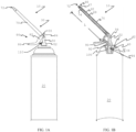
- Figures 1-4 do not illustrate the full breadth of the invention but only embodiments of the elements of the invention to illustrate how they can fit together or be manifest.
- the broadest scope of the invention is intended to allow for embodiments of components as taught herein to be combined in any way physically allowable within the scope of the teaching and not be specifically limited to that illustrated in Figures 1-4 .
- Figures 1-4 do illustrate embodiments of the invention.
- the present invention is an article (10) comprising a can (20) and a dispenser (30).
- Figures 1A and 1B illustrate a side view and a cut-away side view of one type of article of the present invention, respectively.
- the article is useful for dispensing compressed fluid from the can through the dispenser.
- the article may include a can containing a liquid such as dairy product, polyurethane foam formulation or latex foam formulation.
- the can has a valve (40). Pressurized fluid in the can dispenses through the valve.
- the valve is a "Pageris-type" valve, which means it includes a valve cup (42) surrounding a stationary valve stem housing (44) in which a depressible valve stem (46) resides.
- Figure 2 illustrates a cut-away side view of an example of a Pageris-type valve of the present invention.
- the stationary valve stem housing has a top side (48).
- the depressible valve stem extends out from the top side of the stationary valve stem housing or is accessible within the valve stem housing through the top side of the valve stem housing.
- the stationary valve stem housing is typically a cylindrical structure.
- the stationary valve stem housing is rigidly attached to the valve cup so that it cannot tip, bend or compress relative to the valve cup.
- valve stem It serves the purpose of protecting the valve stem from accidentally being depressed.
- Depressing the valve stem that is, displacing the valve stem towards the can within the valve stem housing
- the valve stem is depressed so as to open the valve then the valve and valve stem are in an "open position", otherwise they are in a "closed position".
- the valve stem is in the closed position the can is sealed shut.
- the pressure from the can, or an elastic element (such as a spring) between the valve cup and valve stem keeps the valve stem in a closed position until actively depressed to the open position.
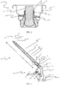
- the dispenser comprises a base (50), a straw (60), a sleeve (70), a trigger (80) and a plunger (90).
- Figure 3 illustrates a cut-away side view of one form of dispenser within the scope of the present invention.
- the base (50) of the dispenser has a side (52), a bottom (54) and a top (55).
- the base defines an entrance opening (54) through the bottom and into a flow channel (58).
- the flow channel is defined and provides fluid communication all the way through the base within the side extending through bottom and top of the base.
- the base of the dispenser desirably is free of any portion that fastens to the valve cup by extending over the top of the valve cup, for example clipping onto the valve cup over the top of the valve cup.
- Figures 4A and 4B illustrate a dispenser having a base that is fit within the valve cup and that is free of any portion that fastens to the valve cup by extending over the top of the valve cup.
- the dispenser can screw onto the valve in order to facilitate attachment to the valve and can. That is, the dispenser and valve can engage with one another with threading that mates in a threaded manner.
- the outside of the base wall and the inside of the valve cup can have threading (100) that mate in a threaded manner.
- the inside of flow channel of the base proximate to the entrance opening and the outside of the stationary valve stem housing can have threading (105) that mate in a threaded manner.
- the "outside of the base wall” or the "outer surface of the base wall” refers to the portion of the base wall most proximate to the valve cup and opposite that portion of the base wall most proximate to the base flow channel.
- the “inside of the valve cup” or the “inner surface of the valve cup” refers to the portion of the valve cup within the cupped domain defined by the valve cup and the portion of the valve cup that is most proximate to the dispenser base wall.
- the “outside of the stationary valve stem housing” or the outer surface of the stationary valve stem housing” refers to the portion of the valve stem housing on the outer surface of the tubular configuration of the valve stem housing, the surface of the valve stem housing opposing the valve stem.
- the “inside of the entrance opening and/or flow channel of the base” refers to the “inner surface of the entrance opening and/or flow channel of the base”.
- the straw (60) of the dispenser has a straw wall (62) separating an entrance end (64) and an exit end (66) on opposing ends of the straw and separated by a length (L) of the straw.
- the straw wall defines a straw flow channel (68) that extends from an entrance opening (65) defined through the straw proximate to the entrance end, through the length of the straw and through an exit opening (67) defined through the straw proximate to the exit end.
- the straw can have one or multiple exit openings defined through the straw proximate to the exit end.
- the straw is attached proximate to its entrance end (preferably at its entrance end) to the base proximate to the top of the base (preferably at the top of the base) such that there is fluid communication from the flow channel of the base through the entrance opening and into the flow channel of the straw.
- the straw can attach to the base by fitting over a portion of the wall of the base surrounding the flow channel through the base; that is, by inserting a portion of the wall around the blow channel of the base that includes the top of the base into the flow channel of the straw through the entrance end of the straw.
- the flow channel through the base and the straw flow channel form a dispenser flow channel that extends continuously through dispenser from the entrance opening in the base through the exit opening of the straw.
- the sleeve (70) extends over at least a portion of the straw along the straw's length.
- the sleeve can extend over the exit end of the straw as well as along at least a portion of the straw's length. Alternatively, the sleeve can be free of a portion that extends over the exit end of the straw.
- the sleeve has an exit opening (72) extending through the sleeve proximate to the exit end of the straw. When fluid is dispensed through the dispenser it travel through the flow channel of the dispenser and out from the exit opening of the straw and through the exit opening in the sleeve.
- a gasket (74) extending circumferentially around the straw between the entrance opening and exit opening of the straw (preferably, proximate to the exit opening) and between the sleeve and the straw that contacts both the sleeve and straw wall so as to form a seal between the two around the straw.
- a gasket serves to preclude fluid from flowing between the straw and sleeve.
- Suitable gaskets include an O-ring. The gasket can reside in a groove in the straw wall, the sleeve, both the sleeve and straw wall or just reside freely without residing in any groove.
- the sleeve is able to slide over the straw along the straw's length. Desirably, the sleeve slides along the straw between a "closed position” and an “open position". When the sleeve is in a “closed position” it seals all exit openings of the straw, preventing fluid flow from the dispenser flow channel through any exit opening in the straw. When the sleeve is in an "open position” the sleeve is free from at least one exit opening of the straw meaning fluid is free to flow from the flow channel through the straw through the exit opening of the straw. Desirably, sliding the sleeve towards the exit end of the straw when the sleeve is in a closed position moves the sleeve into an open position. Similarly, sliding the sleeve towards the entrance end of the straw when the sleeve is in an open position will move the sleeve into a closed position.
- the sleeve When the sleeve is in a closed position the sleeve seals the exit opening of the straw. This precludes dripping of fluid from the dispenser when closed.
- the means of sealing the exit end of the straw is without limit.
- the sleeve can press against the straw wall around and extend over the exit opening thereby blocking fluid communication from the straw flow channel through the exit opening of the straw. Examples of such a means of the sleeve sealing the exit opening of the straw are taught in WO2017/139128 .
- the straw can have a tapered exit end with one or multiple exit openings and the sleeve can have a tapered exit end that conforms to the taper on the straw and presses against the straw when in the closed position so as to seal the exit opening(s) of the straw.
- the sleeve can additionally or alternatively comprise a protrusion that extends at least partially into the exit opening of the straw to seal the exit opening when in the closed position. Examples of such means by which the sleeve seals the exit opening of the straw when in the closed position are taught in WO2017/139131 .
- the exit opening of the straw can be through the exit end of the straw and the sleeve can define a protrusion that extends into the exit opening of the straw when in the closed position.
- the sleeve desirably has one or more than one exit opening around the protrusion to allow fluid to flow out from between the straw and sleeve when in the open position.
- the straw can have one or more than one exit opening through the straw wall proximate to but not on the exit end of the straw and the sleeve can have a protrusion for each exit opening of the straw that fits into each exit opening to seal them when the sleeve is in the closed position.
- the sleeve can either extend over the exit end of the straw and have exit opening(s) through its wall or be free of any portion of sleeve that extends over the exit end of the straw and essentially have an exit opening over the exit end of the straw.
- the base and/or straw can have a protrusion around which a portion of the trigger extends and a pin can extend through the protrusion and portion of the trigger to establish a hinged attachment.
- the trigger can attach to the base and/or straw by means of a flexible material or an article comprising a flexible or compressible element that allows for hinged bending of the trigger with respect to the straw.
- the trigger has a sleeve engagement portion (84) that engages the sleeve above the hinge point. That is, the location where the sleeve engagement portion engages the sleeve is closer to the exit opening of the sleeve than where the trigger hingedly attaches to the base and/or straw.
- the sleeve engagement portion can engage the sleeve in any manner that allows movement of the sleeve engagement portion relative to the straw to cause the sleeve to move along the length of the straw.
- the sleeve engagement portion can engage the sleeve by extending protrusions on either side of the sleeve within a groove defined on the sleeve.
- the sleeve engagement portion can define an eyelet that extends circumferentially around the sleeve and that resides at least partially within a groove of the sleeve and/or between protrusions in the sleeve.
- the means by which the sleeve engagement portion engages the sleeve is unlimited provided that it allows displacement of the sleeve engagement portion relative to the straw to induce the sleeve to slide along the length of the straw.
- the trigger has a trigger arm (86) that extends below the hinge point. That is, the trigger arm extends from the hinge point in a direction generally opposite from the sleeve engagement portion so that moving the trigger arm in the general direction of the dispenser base causes the trigger to hinge at the hinge point and displace the sleeve engagement portion towards the exit end of the straw.
- the trigger arm is generally long enough to allow a user's finger to be placed on it and to apply pressure to the trigger arm in order to actuate the sleeve to an open position from a closed position.
- the trigger and trigger arm are in a "closed" position when located so as to allow the sleeve to be in a closed position.
- the trigger and trigger arm are in an "open" position when they are located in a position that causes the sleeve to be in an open position. Depressing the trigger arm generally towards the can while in the closed position typically displaces the trigger arm and sleeve into their open positions.
- the elastic element located between the trigger arm and base and/or straw that establishes a force on the trigger arm directing the trigger arm to a closed position while in the open position.
- the elastic element can be a spring that is compressed when a force is applied to the trigger that moves it from its closed position to its open position, and a restorative force of the spring applies a force to restore the trigger to its closed position when the applied force is removed.
- the plunger (90) extends from the trigger arm through the side of the base and into the flow channel of the base. While the plunger extends into the flow channel of the base, there remains fluid communication through and/or around the plunger within the flow channel of the base and within the flow channel of the dispenser as a whole. That is, the plunger does not seal off fluid communication through the flow channel of the dispenser.
- the plunger can have a size that allows fluid communication around it within the flow channel. Alternatively, or additionally, the plunger can have one or more than one opening defined therethrough that establishes fluid communication through the plunger within the flow channel.
- the plunger is free to move through the wall of the base wall as opposed to being rigidly attached to the wall of the base.
- a gasket 92 between the plunger and wall of the base to form a fluid-tight seal between the plunger and wall to preclude leaking of fluid from the flow channel of the base through the wall around the plunger.
- An example of a suitable gasket is an O-ring that extends around the plunger. The gasket can reside in a groove in the wall of the base and/or in a groove around the plunger to hold the gasket in place.
- the plunger extends from the trigger arm, which means it extends from a point close enough to the trigger arm that, upon actuating the trigger arm so as to slide the sleeve to an open position, also causes the trigger arm to depress the plunger into the base of the dispenser.
- the plunger can be attached to the trigger arm or be unattached to the trigger arm.
- the plunger extends into the flow channel of the base far enough that when the dispenser is attached to the valve of the can, the valve stem of the can remains in its closed position when the trigger is in its closed position but the trigger causes the plunger to depress the valve stem and open the valve of the can when the trigger is in its open position.
- the plunger can move away from the valve stem sufficiently far so as to allow the valve stem to move to its closed position.
- Figure 4A shows an article of the present invention where the trigger is in its closed position with the plunger extending into the flow channel of the dispenser but not depressing the valve stem so as to cause it to open the valve.
- the sleeve is also in a closed position.
- Figure 4B show the trigger in its open position with the plunger extending into the flow channel of the dispenser and depressing the valve stem so as to cause it to open the valve, and with the sleeve displaced along the straw to its open position.
- elastic element (110) applies a restorative force directing the trigger to its closed position as illustrated in Figure 4A .
- the trigger simultaneously activates both the sleeve and the valve stem by moving them both from a closed position to an open position, or from an open position to a closed position with a single action.
- the dispenser serves as a "single action" dispenser for a Pageris-type valve.
- a benefit of simultaneously activating the sleeve with the can valve is that the dispenser can seal the straw from dripping when closing the valve to the can, and open the straw for dispensing when opening the valve to the can.
Landscapes
- Chemical & Material Sciences (AREA)
- Dispersion Chemistry (AREA)
- Engineering & Computer Science (AREA)
- Mechanical Engineering (AREA)
- Containers And Packaging Bodies Having A Special Means To Remove Contents (AREA)
- Nozzles (AREA)
- Closures For Containers (AREA)
Claims (6)
- Article (10) comprenant une boîte (20) et un distributeur (30), dans lequel :(a) la boîte (20) a une soupape (40) qui inclut une coupelle de soupape (42) entourant un logement de tige de soupape stationnaire (44) dans lequel une tige de soupape pouvant être enfoncée (46) réside et qui s'étend depuis ou est accessible à travers un côté supérieur (48) du logement de tige de soupape stationnaire (44) ; et(b) le distributeur (30) comprend ;(i) une embase (50) qui a un côté (52), un fond (54) et un dessus (55) avec une ouverture d'entrée (56) vers un canal d'écoulement (58) défini à travers le fond (54) et s'étendant à travers l'embase (50) et hors du dessus (55), l'embase (50) s'insérant dans la coupelle de soupape (42) de la boîte (20) avec le logement de tige de soupape stationnaire (44) inséré dans l'ouverture d'entrée (56) de l'embase (50) lorsqu'il est fixé à la soupape (40) de la boîte (20) ;(ii) une paille (60) ayant une paroi de paille (62) séparant les extrémités opposées d'entrée (64) et de sortie (66) par une longueur (L) où la paroi de paille (62) définit un canal d'écoulement de la paille (68) qui s'étend d'une ouverture d'entrée (65) définie à travers la paille (60) à proximité de l'extrémité d'entrée (64) à travers une ouverture de sortie (67) définie à travers la paille (60) à proximité de l'extrémité de sortie (66) et où la paille (60) est fixée à proximité de son extrémité d'entrée (64) à la base à proximité du sommet (55) de l'embase (50) de sorte qu'il existe une communication fluidique depuis le canal d'écoulement (58) de l'embase (50) à travers l'ouverture d'entrée (56) et dans le canal d'écoulement (68) de la paille (60) où le canal d'écoulement de l'embase (58) et le canal d'écoulement de la paille (68) forment un canal d'écoulement de distributeur continu s'étendant à travers l'ouverture d'entrée (56) de l'embase (50) à travers le distributeur (30) et ressort par l'ouverture de sortie (67) de la paille (60) ;(iii) un manchon (70) s'étendant sur au moins une partie de la longueur (L) de la paille (60) et apte à coulisser sur la paille (60) sur au moins une partie de la longueur (L) de la paille (60), le manchon (70) ayant une ouverture de sortie (72) s'étendant à travers le manchon (70) à proximité de l'extrémité de sortie (66) de la paille (60) ; et(iv) un déclencheur (80) fixé de manière articulée à l'embase (50) et/ou à la paille (60) du distributeur (30) en un point d'articulation (82) de sorte que le déclencheur (80) peut se déplacer sans déplacer la paille (60) ou l'embase (50) et ayant une partie d'engagement de manchon (84) du déclencheur (80) qui engage le manchon (70) au-dessus du point d'articulation (82) et un bras de déclenchement (86) s'étendant en dessous du point d'articulation (82);dans lequel le distributeur (30) peut être fixé à la soupape (40) de la boîte (20) en insérant le boîtier de tige de soupape stationnaire (44) dans l'ouverture d'entrée (56) du canal d'écoulement (58) de l'embase du distributeur (50) en insérant l'embase du distributeur (50) dans la coupelle de soupape (42) de la soupape (40) ;caractérisé en ce que le distributeur (30) comprend en outre :(v) un plongeur (90) s'étendant depuis le bras de déclenchement (86) du déclencheur (80), à travers un côté (52) de l'embase (50) et dans le canal d'écoulement (58) de l'embase (50) tout en maintenant une communication fluidique à travers et/ou autour du piston (90) à l'intérieur du canal d'écoulement (58) du distributeur (30);dans lequel le piston (90) s'étend dans le canal d'écoulement du distributeur (58) suffisamment loin pour que lorsque le distributeur (30) est fixé à la soupape (40) de la boîte (20), la tige de soupape abaissée (46) est dans un position fermée qui scelle la soupape de boîte (40) tandis que le bras de déclenchement (86) est dans une position fermée, et le déplacement du bras de déclenchement (86) de la position fermée à une position ouverte amène le manchon (70) à coulisser le long de la paille (60) en s'éloignant de l'ouverture d'entrée (65) de la paille (60) et amène le plongeur (90) à enfoncer la tige de soupape à pression (46) dans une position ouverte.
- Article selon la revendication 1, dans lequel : (a) une surface externe de la paroi de l'embase et une surface interne de la coupelle de soupape (42) ont un filetage (100) qui s'accouple d'une manière filetée ; ou (b) une surface interne de l'ouverture d'entrée (65) et/ou du canal d'écoulement (58) de l'embase (50) et une surface externe du boîtier de tige de soupape stationnaire (44) ont un filetage (105) qui s'accouple d'une manière filetée ; ou (c) à la fois la surface externe de la paroi de l'embase et la surface interne de la coupelle de soupape (42) ont un filetage qui s'accouple de manière filetée et la surface interne de l'ouverture d'entrée et/ou du canal d'écoulement (58) de l'embase (50) et la surface externe du boîtier de tige de soupape fixe (44) a un filetage qui s'accouple de manière filetée.
- Article selon la revendication 1 ou la revendication 2, dans lequel le piston (90) n'est pas fixé au bras de déclenchement (86).
- Article selon la revendication 1 ou la revendication 2, dans lequel un article élastique (110) qui applique une force de rappel dirigeant le bras de déclenchement (86) vers sa position neutre lorsque le bras de déclenchement (86) est déplacé vers la boîte (20) réside entre le bras de déclenchement (86) et l'embase (50) et/ou la paille (60) du distributeur (30).
- Article selon la revendication 1 ou la revendication 2, dans lequel le manchon (70) a une position fermée par rapport à la paille (60) dans laquelle le manchon (70) obture l'ouverture de sortie (67) de la paille (60) et, lorsque le manchon (70) s'éloigne de la position fermée de l'extrémité d'entrée (64) de la paille (60), il descelle l'ouverture de sortie (67) de la paille (60) amenant le manchon (70) à se trouver dans une position ouverte dans laquelle il y a une communication fluidique depuis le canal d'écoulement de paille (68) à travers l'ouverture de sortie de la paille (67) et à travers l'ouverture de sortie de manchon (72).
- Article selon la revendication 1 ou la revendication 2, dans lequel le distributeur (30) comprend en outre un joint (74) s'étendant circonférentiellement autour de la paille (60) entre la paille (60) et le manchon (70) et situé sur la longueur (L) de la paille (60) entre l'ouverture d'entrée (65) et l'ouverture de sortie (67) de la paille (60).
Applications Claiming Priority (2)
| Application Number | Priority Date | Filing Date | Title |
|---|---|---|---|
| US201862655284P | 2018-04-10 | 2018-04-10 | |
| PCT/US2019/026694 WO2019199907A1 (fr) | 2018-04-10 | 2019-04-10 | Distributeur de boîte doté d'un boîtier de tige de valve fixe |
Publications (2)
| Publication Number | Publication Date |
|---|---|
| EP3774591A1 EP3774591A1 (fr) | 2021-02-17 |
| EP3774591B1 true EP3774591B1 (fr) | 2023-03-01 |
Family
ID=66248841
Family Applications (1)
| Application Number | Title | Priority Date | Filing Date |
|---|---|---|---|
| EP19719109.1A Active EP3774591B1 (fr) | 2018-04-10 | 2019-04-10 | Distributeur de boîte doté d'un boîtier de tige de valve fixe |
Country Status (9)
| Country | Link |
|---|---|
| US (1) | US10526132B2 (fr) |
| EP (1) | EP3774591B1 (fr) |
| JP (1) | JP7364582B2 (fr) |
| CN (1) | CN112041240B (fr) |
| CA (1) | CA3095513A1 (fr) |
| DK (1) | DK3774591T3 (fr) |
| ES (1) | ES2940785T3 (fr) |
| FI (1) | FI3774591T3 (fr) |
| WO (1) | WO2019199907A1 (fr) |
Families Citing this family (5)
| Publication number | Priority date | Publication date | Assignee | Title |
|---|---|---|---|---|
| KR102497514B1 (ko) * | 2016-10-20 | 2023-02-09 | 다우 글로벌 테크놀로지스 엘엘씨 | 단일 손가락 분무 물품 |
| DK3339212T3 (da) * | 2016-12-23 | 2021-05-10 | Doc Bibawo As | Aerosoldispensere og beholdere og hoveder til sådanne beholdere |
| BR112022023486A2 (pt) * | 2020-05-19 | 2023-01-10 | Recurium Ip Holdings Llc | Tratamento para amiloidose |
| US12269668B2 (en) * | 2022-01-12 | 2025-04-08 | Seymour Of Sycamore Inc. | Aerosol can activator |
| IT202300009555A1 (it) * | 2023-05-12 | 2024-11-12 | Altergon Sa | Dispositivo di erogazione di prodotti liquidi o semisolidi, particolarmente di farmaci, dispositivi medici o prodotti cosmetici |
Family Cites Families (24)
| Publication number | Priority date | Publication date | Assignee | Title |
|---|---|---|---|---|
| US3506241A (en) | 1967-07-06 | 1970-04-14 | Pittsburgh Railways Co | Tilt valve |
| DE2128080A1 (de) | 1971-06-05 | 1972-12-14 | Traynor, John S., Palo Alto, Calif. (V.St.A.) | Sprühdüsenanordnung |
| US4436229A (en) | 1982-08-05 | 1984-03-13 | Beard Walter C | High flow tilt valve with accelerating cam equipped moveable cup |
| US4856684A (en) | 1987-04-06 | 1989-08-15 | William Gerstung | Valve for a pressurized dispensing can containing flowable materials |
| US5154323A (en) * | 1991-01-22 | 1992-10-13 | Query Grady W | Aerosol applicator and actuator |
| US5524798A (en) * | 1992-02-24 | 1996-06-11 | Djs&T Limited Partnership | Spray texturing nozzles having variable orifice |
| DE4313319B4 (de) * | 1993-04-23 | 2006-09-28 | C. Ehrensperger Ag | Vorrichtung für Betätigungsvorrichtungen für Treibmitteldosen |
| US5887756A (en) * | 1994-06-23 | 1999-03-30 | Insta-Foam Products, Inc. | Dispensing gun with valving rod and bellows-type seal |
| DE10252161A1 (de) | 2002-11-09 | 2004-05-27 | Thomas Gmbh | Druckbehältnis, insbesondere für gefrorene Substanzen |
| GB0307445D0 (en) * | 2003-03-31 | 2003-05-07 | Glaxo Group Ltd | Novel device |
| TWI355357B (en) * | 2005-01-26 | 2012-01-01 | Fumakilla Ltd | Head cap for aerosol type atomizer |
| DE102007041986A1 (de) * | 2007-09-05 | 2009-03-12 | Henkel Ag & Co. Kgaa | Druckverpackung für viskose Materialien |
| BE1020534A5 (nl) * | 2010-06-04 | 2013-12-03 | Soudal | Schroefkoppelstuk met dubbele functie. |
| US20120097180A1 (en) * | 2010-10-21 | 2012-04-26 | Henkel Consumer Goods Inc. | Actuator for dispensing aerosol hair care products closer to the scalp |
| US20120204379A1 (en) * | 2011-02-11 | 2012-08-16 | Isenhour Micah C | Nozzle-based aerosol cleaner for optical connectors |
| ES2539401T3 (es) * | 2011-02-25 | 2015-06-30 | Dow Global Technologies Llc | Dispositivo dispensador de fluido comprimido activado por manga, con obturación interna |
| JP5912137B2 (ja) * | 2011-02-25 | 2016-04-27 | ダウ グローバル テクノロジーズ エルエルシー | 内部シール付き圧縮流体分配装置 |
| US9010572B2 (en) * | 2012-12-11 | 2015-04-21 | Altachem N. V. | Tip seal having a position indicator, the tip seal being configured to dispense a foam solution |
| US9352896B2 (en) * | 2013-03-14 | 2016-05-31 | Berry Plastics Corporation | Dispenser apparatus |
| JP6140559B2 (ja) * | 2013-07-18 | 2017-05-31 | 株式会社三谷バルブ | シャッタートリガ機構ならびにシャッタートリガ機構を備えたエアゾール式製品およびポンプ式製品 |
| BE1022385B1 (nl) * | 2015-02-02 | 2016-03-18 | Altachem N.V. | Een bevestigingsgeheel voor het bevestigen van een adapter aan een ventielsteel. |
| CA3013755C (fr) | 2016-02-09 | 2024-01-23 | Dow Global Technologies Llc | Dispositif de distribution a action unique avec manchon coulissant ayant un bouton |
| HUE054896T2 (hu) * | 2016-02-09 | 2021-10-28 | Ddp Specialty Electronic Mat Us Inc | Egymûködtetésû adagolóberendezés csúszóhüvellyel |
| JP7057353B2 (ja) * | 2016-10-20 | 2022-04-19 | ダウ グローバル テクノロジーズ エルエルシー | キャップ付きディスペンサ |
-
2019
- 2019-04-10 CA CA3095513A patent/CA3095513A1/fr active Pending
- 2019-04-10 US US16/379,840 patent/US10526132B2/en active Active
- 2019-04-10 JP JP2020550070A patent/JP7364582B2/ja active Active
- 2019-04-10 ES ES19719109T patent/ES2940785T3/es active Active
- 2019-04-10 DK DK19719109.1T patent/DK3774591T3/da active
- 2019-04-10 WO PCT/US2019/026694 patent/WO2019199907A1/fr not_active Ceased
- 2019-04-10 EP EP19719109.1A patent/EP3774591B1/fr active Active
- 2019-04-10 CN CN201980019407.XA patent/CN112041240B/zh active Active
- 2019-04-10 FI FIEP19719109.1T patent/FI3774591T3/fi active
Also Published As
| Publication number | Publication date |
|---|---|
| JP2021518312A (ja) | 2021-08-02 |
| EP3774591A1 (fr) | 2021-02-17 |
| WO2019199907A1 (fr) | 2019-10-17 |
| US10526132B2 (en) | 2020-01-07 |
| JP7364582B2 (ja) | 2023-10-18 |
| ES2940785T3 (es) | 2023-05-11 |
| FI3774591T3 (fi) | 2023-05-05 |
| CN112041240B (zh) | 2022-08-26 |
| US20190308798A1 (en) | 2019-10-10 |
| DK3774591T3 (da) | 2023-03-20 |
| CN112041240A (zh) | 2020-12-04 |
| CA3095513A1 (fr) | 2019-10-17 |
Similar Documents
| Publication | Publication Date | Title |
|---|---|---|
| EP3774591B1 (fr) | Distributeur de boîte doté d'un boîtier de tige de valve fixe | |
| US10611554B2 (en) | Dispenser for valve with stationary valve stem housing | |
| EP3414181B1 (fr) | Dispositif de distribution à action unique à manchon coulissant | |
| EP3414182B1 (fr) | Dispositif de distribution à action unique avec manchon coulissant ayant un bouton | |
| US10919687B2 (en) | Dispenser with cap | |
| US10919688B2 (en) | Single finger dispensing article | |
| US10632486B2 (en) | Dispenser adapter |
Legal Events
| Date | Code | Title | Description |
|---|---|---|---|
| STAA | Information on the status of an ep patent application or granted ep patent |
Free format text: STATUS: UNKNOWN |
|
| STAA | Information on the status of an ep patent application or granted ep patent |
Free format text: STATUS: THE INTERNATIONAL PUBLICATION HAS BEEN MADE |
|
| PUAI | Public reference made under article 153(3) epc to a published international application that has entered the european phase |
Free format text: ORIGINAL CODE: 0009012 |
|
| STAA | Information on the status of an ep patent application or granted ep patent |
Free format text: STATUS: REQUEST FOR EXAMINATION WAS MADE |
|
| 17P | Request for examination filed |
Effective date: 20201020 |
|
| AK | Designated contracting states |
Kind code of ref document: A1 Designated state(s): AL AT BE BG CH CY CZ DE DK EE ES FI FR GB GR HR HU IE IS IT LI LT LU LV MC MK MT NL NO PL PT RO RS SE SI SK SM TR |
|
| AX | Request for extension of the european patent |
Extension state: BA ME |
|
| RAP3 | Party data changed (applicant data changed or rights of an application transferred) |
Owner name: DDP SPECIALTY ELECTRONIC MATERIALS US, LLC |
|
| DAV | Request for validation of the european patent (deleted) | ||
| DAX | Request for extension of the european patent (deleted) | ||
| STAA | Information on the status of an ep patent application or granted ep patent |
Free format text: STATUS: EXAMINATION IS IN PROGRESS |
|
| 17Q | First examination report despatched |
Effective date: 20211105 |
|
| GRAP | Despatch of communication of intention to grant a patent |
Free format text: ORIGINAL CODE: EPIDOSNIGR1 |
|
| STAA | Information on the status of an ep patent application or granted ep patent |
Free format text: STATUS: GRANT OF PATENT IS INTENDED |
|
| INTG | Intention to grant announced |
Effective date: 20221013 |
|
| GRAS | Grant fee paid |
Free format text: ORIGINAL CODE: EPIDOSNIGR3 |
|
| GRAA | (expected) grant |
Free format text: ORIGINAL CODE: 0009210 |
|
| STAA | Information on the status of an ep patent application or granted ep patent |
Free format text: STATUS: THE PATENT HAS BEEN GRANTED |
|
| AK | Designated contracting states |
Kind code of ref document: B1 Designated state(s): AL AT BE BG CH CY CZ DE DK EE ES FI FR GB GR HR HU IE IS IT LI LT LU LV MC MK MT NL NO PL PT RO RS SE SI SK SM TR |
|
| REG | Reference to a national code |
Ref country code: GB Ref legal event code: FG4D |
|
| REG | Reference to a national code |
Ref country code: CH Ref legal event code: EP Ref country code: AT Ref legal event code: REF Ref document number: 1550825 Country of ref document: AT Kind code of ref document: T Effective date: 20230315 |
|
| REG | Reference to a national code |
Ref country code: DE Ref legal event code: R096 Ref document number: 602019025836 Country of ref document: DE |
|
| REG | Reference to a national code |
Ref country code: DK Ref legal event code: T3 Effective date: 20230317 |
|
| REG | Reference to a national code |
Ref country code: IE Ref legal event code: FG4D |
|
| REG | Reference to a national code |
Ref country code: ES Ref legal event code: FG2A Ref document number: 2940785 Country of ref document: ES Kind code of ref document: T3 Effective date: 20230511 |
|
| REG | Reference to a national code |
Ref country code: NO Ref legal event code: T2 Effective date: 20230301 |
|
| REG | Reference to a national code |
Ref country code: NL Ref legal event code: FP |
|
| REG | Reference to a national code |
Ref country code: SE Ref legal event code: TRGR |
|
| REG | Reference to a national code |
Ref country code: LT Ref legal event code: MG9D |
|
| P01 | Opt-out of the competence of the unified patent court (upc) registered |
Effective date: 20230528 |
|
| PG25 | Lapsed in a contracting state [announced via postgrant information from national office to epo] |
Ref country code: RS Free format text: LAPSE BECAUSE OF FAILURE TO SUBMIT A TRANSLATION OF THE DESCRIPTION OR TO PAY THE FEE WITHIN THE PRESCRIBED TIME-LIMIT Effective date: 20230301 Ref country code: LV Free format text: LAPSE BECAUSE OF FAILURE TO SUBMIT A TRANSLATION OF THE DESCRIPTION OR TO PAY THE FEE WITHIN THE PRESCRIBED TIME-LIMIT Effective date: 20230301 Ref country code: LT Free format text: LAPSE BECAUSE OF FAILURE TO SUBMIT A TRANSLATION OF THE DESCRIPTION OR TO PAY THE FEE WITHIN THE PRESCRIBED TIME-LIMIT Effective date: 20230301 Ref country code: HR Free format text: LAPSE BECAUSE OF FAILURE TO SUBMIT A TRANSLATION OF THE DESCRIPTION OR TO PAY THE FEE WITHIN THE PRESCRIBED TIME-LIMIT Effective date: 20230301 |
|
| REG | Reference to a national code |
Ref country code: AT Ref legal event code: MK05 Ref document number: 1550825 Country of ref document: AT Kind code of ref document: T Effective date: 20230301 |
|
| PG25 | Lapsed in a contracting state [announced via postgrant information from national office to epo] |
Ref country code: PL Free format text: LAPSE BECAUSE OF FAILURE TO SUBMIT A TRANSLATION OF THE DESCRIPTION OR TO PAY THE FEE WITHIN THE PRESCRIBED TIME-LIMIT Effective date: 20230301 Ref country code: GR Free format text: LAPSE BECAUSE OF FAILURE TO SUBMIT A TRANSLATION OF THE DESCRIPTION OR TO PAY THE FEE WITHIN THE PRESCRIBED TIME-LIMIT Effective date: 20230602 |
|
| PG25 | Lapsed in a contracting state [announced via postgrant information from national office to epo] |
Ref country code: SM Free format text: LAPSE BECAUSE OF FAILURE TO SUBMIT A TRANSLATION OF THE DESCRIPTION OR TO PAY THE FEE WITHIN THE PRESCRIBED TIME-LIMIT Effective date: 20230301 Ref country code: RO Free format text: LAPSE BECAUSE OF FAILURE TO SUBMIT A TRANSLATION OF THE DESCRIPTION OR TO PAY THE FEE WITHIN THE PRESCRIBED TIME-LIMIT Effective date: 20230301 Ref country code: PT Free format text: LAPSE BECAUSE OF FAILURE TO SUBMIT A TRANSLATION OF THE DESCRIPTION OR TO PAY THE FEE WITHIN THE PRESCRIBED TIME-LIMIT Effective date: 20230703 Ref country code: EE Free format text: LAPSE BECAUSE OF FAILURE TO SUBMIT A TRANSLATION OF THE DESCRIPTION OR TO PAY THE FEE WITHIN THE PRESCRIBED TIME-LIMIT Effective date: 20230301 Ref country code: CZ Free format text: LAPSE BECAUSE OF FAILURE TO SUBMIT A TRANSLATION OF THE DESCRIPTION OR TO PAY THE FEE WITHIN THE PRESCRIBED TIME-LIMIT Effective date: 20230301 Ref country code: AT Free format text: LAPSE BECAUSE OF FAILURE TO SUBMIT A TRANSLATION OF THE DESCRIPTION OR TO PAY THE FEE WITHIN THE PRESCRIBED TIME-LIMIT Effective date: 20230301 |
|
| PG25 | Lapsed in a contracting state [announced via postgrant information from national office to epo] |
Ref country code: SK Free format text: LAPSE BECAUSE OF FAILURE TO SUBMIT A TRANSLATION OF THE DESCRIPTION OR TO PAY THE FEE WITHIN THE PRESCRIBED TIME-LIMIT Effective date: 20230301 Ref country code: IS Free format text: LAPSE BECAUSE OF FAILURE TO SUBMIT A TRANSLATION OF THE DESCRIPTION OR TO PAY THE FEE WITHIN THE PRESCRIBED TIME-LIMIT Effective date: 20230701 |
|
| REG | Reference to a national code |
Ref country code: CH Ref legal event code: PL |
|
| REG | Reference to a national code |
Ref country code: DE Ref legal event code: R097 Ref document number: 602019025836 Country of ref document: DE |
|
| PG25 | Lapsed in a contracting state [announced via postgrant information from national office to epo] |
Ref country code: LU Free format text: LAPSE BECAUSE OF NON-PAYMENT OF DUE FEES Effective date: 20230410 |
|
| PLBE | No opposition filed within time limit |
Free format text: ORIGINAL CODE: 0009261 |
|
| STAA | Information on the status of an ep patent application or granted ep patent |
Free format text: STATUS: NO OPPOSITION FILED WITHIN TIME LIMIT |
|
| PG25 | Lapsed in a contracting state [announced via postgrant information from national office to epo] |
Ref country code: MC Free format text: LAPSE BECAUSE OF FAILURE TO SUBMIT A TRANSLATION OF THE DESCRIPTION OR TO PAY THE FEE WITHIN THE PRESCRIBED TIME-LIMIT Effective date: 20230301 |
|
| PG25 | Lapsed in a contracting state [announced via postgrant information from national office to epo] |
Ref country code: SI Free format text: LAPSE BECAUSE OF FAILURE TO SUBMIT A TRANSLATION OF THE DESCRIPTION OR TO PAY THE FEE WITHIN THE PRESCRIBED TIME-LIMIT Effective date: 20230301 Ref country code: MC Free format text: LAPSE BECAUSE OF FAILURE TO SUBMIT A TRANSLATION OF THE DESCRIPTION OR TO PAY THE FEE WITHIN THE PRESCRIBED TIME-LIMIT Effective date: 20230301 Ref country code: LI Free format text: LAPSE BECAUSE OF NON-PAYMENT OF DUE FEES Effective date: 20230430 Ref country code: CH Free format text: LAPSE BECAUSE OF NON-PAYMENT OF DUE FEES Effective date: 20230430 |
|
| 26N | No opposition filed |
Effective date: 20231204 |
|
| REG | Reference to a national code |
Ref country code: IE Ref legal event code: MM4A |
|
| PG25 | Lapsed in a contracting state [announced via postgrant information from national office to epo] |
Ref country code: IE Free format text: LAPSE BECAUSE OF NON-PAYMENT OF DUE FEES Effective date: 20230410 |
|
| PG25 | Lapsed in a contracting state [announced via postgrant information from national office to epo] |
Ref country code: IE Free format text: LAPSE BECAUSE OF NON-PAYMENT OF DUE FEES Effective date: 20230410 |
|
| PG25 | Lapsed in a contracting state [announced via postgrant information from national office to epo] |
Ref country code: BG Free format text: LAPSE BECAUSE OF FAILURE TO SUBMIT A TRANSLATION OF THE DESCRIPTION OR TO PAY THE FEE WITHIN THE PRESCRIBED TIME-LIMIT Effective date: 20230301 |
|
| PG25 | Lapsed in a contracting state [announced via postgrant information from national office to epo] |
Ref country code: BG Free format text: LAPSE BECAUSE OF FAILURE TO SUBMIT A TRANSLATION OF THE DESCRIPTION OR TO PAY THE FEE WITHIN THE PRESCRIBED TIME-LIMIT Effective date: 20230301 |
|
| PGFP | Annual fee paid to national office [announced via postgrant information from national office to epo] |
Ref country code: FI Payment date: 20250421 Year of fee payment: 7 |
|
| PGFP | Annual fee paid to national office [announced via postgrant information from national office to epo] |
Ref country code: DE Payment date: 20250305 Year of fee payment: 7 |
|
| PGFP | Annual fee paid to national office [announced via postgrant information from national office to epo] |
Ref country code: DK Payment date: 20250411 Year of fee payment: 7 Ref country code: ES Payment date: 20250506 Year of fee payment: 7 |
|
| PGFP | Annual fee paid to national office [announced via postgrant information from national office to epo] |
Ref country code: NO Payment date: 20250409 Year of fee payment: 7 |
|
| PG25 | Lapsed in a contracting state [announced via postgrant information from national office to epo] |
Ref country code: CY Free format text: LAPSE BECAUSE OF FAILURE TO SUBMIT A TRANSLATION OF THE DESCRIPTION OR TO PAY THE FEE WITHIN THE PRESCRIBED TIME-LIMIT; INVALID AB INITIO Effective date: 20190410 |
|
| PG25 | Lapsed in a contracting state [announced via postgrant information from national office to epo] |
Ref country code: HU Free format text: LAPSE BECAUSE OF FAILURE TO SUBMIT A TRANSLATION OF THE DESCRIPTION OR TO PAY THE FEE WITHIN THE PRESCRIBED TIME-LIMIT; INVALID AB INITIO Effective date: 20190410 |
|
| PG25 | Lapsed in a contracting state [announced via postgrant information from national office to epo] |
Ref country code: TR Free format text: LAPSE BECAUSE OF FAILURE TO SUBMIT A TRANSLATION OF THE DESCRIPTION OR TO PAY THE FEE WITHIN THE PRESCRIBED TIME-LIMIT Effective date: 20230301 |
|
| PGFP | Annual fee paid to national office [announced via postgrant information from national office to epo] |
Ref country code: SE Payment date: 20260312 Year of fee payment: 8 |
|
| PGFP | Annual fee paid to national office [announced via postgrant information from national office to epo] |
Ref country code: GB Payment date: 20260316 Year of fee payment: 8 |
|
| PGFP | Annual fee paid to national office [announced via postgrant information from national office to epo] |
Ref country code: BE Payment date: 20260317 Year of fee payment: 8 Ref country code: IT Payment date: 20260320 Year of fee payment: 8 |
|
| PGFP | Annual fee paid to national office [announced via postgrant information from national office to epo] |
Ref country code: NL Payment date: 20260317 Year of fee payment: 8 |
|
| PGFP | Annual fee paid to national office [announced via postgrant information from national office to epo] |
Ref country code: FR Payment date: 20260309 Year of fee payment: 8 |