EP3774520B1 - Spule für automatische aufblasvorrichtung - Google Patents
Spule für automatische aufblasvorrichtung Download PDFInfo
- Publication number
- EP3774520B1 EP3774520B1 EP19782052.5A EP19782052A EP3774520B1 EP 3774520 B1 EP3774520 B1 EP 3774520B1 EP 19782052 A EP19782052 A EP 19782052A EP 3774520 B1 EP3774520 B1 EP 3774520B1
- Authority
- EP
- European Patent Office
- Prior art keywords
- arms
- bobbin
- spring
- pill
- set forth
- Prior art date
- Legal status (The legal status is an assumption and is not a legal conclusion. Google has not performed a legal analysis and makes no representation as to the accuracy of the status listed.)
- Active
Links
Images


Classifications
-
- B—PERFORMING OPERATIONS; TRANSPORTING
- B63—SHIPS OR OTHER WATERBORNE VESSELS; RELATED EQUIPMENT
- B63C—LAUNCHING, HAULING-OUT, OR DRY-DOCKING OF VESSELS; LIFE-SAVING IN WATER; EQUIPMENT FOR DWELLING OR WORKING UNDER WATER; MEANS FOR SALVAGING OR SEARCHING FOR UNDERWATER OBJECTS
- B63C9/00—Life-saving in water
- B63C9/08—Life-buoys, e.g. rings; Life-belts, jackets, suits, or the like
- B63C9/18—Inflatable equipment characterised by the gas-generating or inflation device
- B63C9/19—Arrangements for puncturing gas-generating cartridges
-
- B—PERFORMING OPERATIONS; TRANSPORTING
- B63—SHIPS OR OTHER WATERBORNE VESSELS; RELATED EQUIPMENT
- B63C—LAUNCHING, HAULING-OUT, OR DRY-DOCKING OF VESSELS; LIFE-SAVING IN WATER; EQUIPMENT FOR DWELLING OR WORKING UNDER WATER; MEANS FOR SALVAGING OR SEARCHING FOR UNDERWATER OBJECTS
- B63C9/00—Life-saving in water
- B63C9/24—Arrangements of inflating valves or of controls thereof
-
- B—PERFORMING OPERATIONS; TRANSPORTING
- B63—SHIPS OR OTHER WATERBORNE VESSELS; RELATED EQUIPMENT
- B63C—LAUNCHING, HAULING-OUT, OR DRY-DOCKING OF VESSELS; LIFE-SAVING IN WATER; EQUIPMENT FOR DWELLING OR WORKING UNDER WATER; MEANS FOR SALVAGING OR SEARCHING FOR UNDERWATER OBJECTS
- B63C9/00—Life-saving in water
- B63C2009/0023—Particular features common to inflatable life-saving equipment
- B63C2009/0029—Inflation devices comprising automatic activation means, e.g. for puncturing gas-generating cartridges
- B63C2009/0041—Inflation devices comprising automatic activation means, e.g. for puncturing gas-generating cartridges activated by presence of water
- B63C2009/0058—Inflation devices comprising automatic activation means, e.g. for puncturing gas-generating cartridges activated by presence of water using means soluble in water, or weakening when wet
Definitions
- This invention relates to automatic inflators for inflatable articles such as life rafts, life vests, and the like. More particularly, this invention relates to inflators that are actuated automatically upon immersion in water.
- Manual inflators typically comprise a body for receiving the neck of a cartridge of compressed gas such as carbon dioxide.
- a reciprocating pierce pin is disposed within the body of the inflator for piercing the frangible seal of the cartridge to permit compressed gas therein to flow into a manifold assembly of the inflator and then into the article to be inflated.
- a manually movable firing lever is operatively connected to the pierce pin such that the pierce pin pierces the frangible seal of the gas cartridge upon jerking of a ball lanyard.
- U.S. Pat. No. 3809288 illustrates one particular embodiment of a manual inflator.
- water-activated automatic inflators were developed which automatically actuate the pierce pin of the inflator when immersed in water thereby causing inflation of the inflatable device.
- Typical water-activated automatic inflators comprise a water activated actuator including a water destructible or dissolvable element, often referred to as a "bobbin", which retains a spring-loaded actuator pin in a cocked position in alignment with the pierce pin.
- bobbin water destructible or dissolvable element
- the spring-loaded actuator pin is thus released to forcibly move from its cocked position to an actuated position to strike the pierce pin, either directly or indirectly by means of an intermediate transfer pin.
- the pin fractures the seal of the cartridge thereby allowing the gas contained therein to flow into the inflatable device to inflate the same.
- a disadvantage to automatic inflators employing a dissolvable pill is the tendency to prematurely destruct in non-emergency situations by exposure of the pill to excessive humidity in the air.
- Bobbin pills of various designs and chemical compositions have been used to minimize their susceptibility to humidity.
- U.S. Patents 6,705,488 and 7,572,161 disclose various configurations for pills for bobbins of automatic inflators that seek to reduce susceptibility to humidity resulting in unintended or premature actuation while maintaining sufficient dissolvability in water so that the pill dissolves upon being submerged in water.
- Another object of this invention is to provide a humidity-resistant bobbin for an automatic inflator that is less susceptible to humid weather conditions that may undesirably prematurely activate the automatic inflator in non-emergency situations due to humidity.
- Another object of this invention is to provide a cold-weather bobbin for an automatic inflator that actuates quickly after being submerged in freezing cold water.
- the invention comprises a humidity-resistant, cold-weather bobbin for a water-activated automatic inflator that is less susceptible to humid weather conditions that may otherwise prematurely activate the automatic inflator while minimizing the amount of time it takes for the bobbin's pill to dissolve in freezing cold water.
- Prior art bobbins comprise a circular housing having internally a collapsible annular ring of individually pivotal arms (e.g., eight arms) extending generally parallel to the axis of the bobbin.
- a toroidal, dissolvable pill is positioned about the ring of individually pivotal arms to retain them in their un-collapsed, generally-parallel position and to prevent them from collapsing outwardly.
- the individually pivotal arms each include an inwardly extending radial step, which collectively form an annular seat to retain a spring-loaded actuator in its cocked position.
- each of the individually pivotal arms and their steps are allowed to individually pivot outwardly under the constant pressure of the actuator to a position no longer parallel to the axis of the bobbin.
- their respective steps likewise move outwardly to expand the diameter of the annular seat until such seat in no longer able to retain the actuator, thereby releasing (i.e., firing) the spring-loaded actuator to force a pierce pin into the frangible seal of a gas cartridge.
- the pill of prior art bobbins comprise microcrystalline cellulose (e.g., Avicel ® PH-102 manufactured by FMC Corporation, 1735 Market Street, Philadelphia, PA 19103) and an accelerant (e.g., AcDiSol accelerant) that is compressed into the desired configurations.
- microcrystalline cellulose e.g., Avicel ® PH-102 manufactured by FMC Corporation, 1735 Market Street, Philadelphia, PA 19103
- an accelerant e.g., AcDiSol accelerant
- This composition is selected for its characteristics of being resistant to moisture from humid weather conditions while maximizing compressive strength.
- the method of compressing the powder into the pill often produces an outer surface that resembles a thin skin that enhances the pill's resistance to humid weather conditions. Indeed, chemical additives may be combined with the cellulose powder to enhance the pill's resistance to humidity and increase its compressed forces.
- the bobbin of the present invention similarly includes a collapsible annular ring of pivotal arms (e.g., eight arms), held in position by a dissolvable pill, to retain the spring-loaded actuator in its cocked position.
- every other pair of adjacent pivotal arms are connected together by an interconnecting web so that they may only pivot outwardly in adjacent pairs instead of individually as in the case of the prior art.
- arms 1 & 2, 3 & 4, 5 & 6 and 7 & 8 are respectively interconnected via a web to form 4 pairs of interconnected pivotal arms.
- webbing adjacent pivotal arms is preferred as described above; however, it should be appreciated that other webbed configurations are possible.
- arms 1 & 2, 4 & 5 and 7 & 8 may be interconnected via a web, allowing unwebbed arms 3 and 6 free to pivot individually.
- arms 1 & 2 and 5 & 6 may be webbed together, allowing unwebbed arms 3, 4, 7 and 8 free to pivot individually.
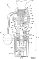
- Fig. 1 copied from U.S. Patent 5,601,124 , illustrates an exemplary prior art automatic inflator 10 as comprising an inflator body 12, an actuator body assembly 14, and a cylindrical cap assembly 16.
- the inflator body 12 has a longitudinal central bore, generally indicated by numeral 18, which is sized to receive a pierce pin assembly 20 reciprocatably positioned therein.
- a gas-containing cartridge 22 is threadably coupled to the inflator body in alignment with the pierce pin assembly 20.
- the pierce pin assembly 20 comprises a pierce pin 24 having an end portion 26, a sealing gasket 28, and a small compression spring 30.
- a conventional metal insert 32 having interior threads 34 and gasket 36, is molded in situ within the inflator body 12.
- the gas-containing cartridge 22 is threaded into the metal insert 32.
- the frangible seal of the gas cartridge 22 is pierced when the pierce pin assembly 20 is forcibly moved towards the cartridge 22.
- the automatic inflator 10 may be fired automatically upon immersion in water or manually.
- the manual actuator means includes a generally L-shaped lever 38 pivotally mounted to the inflator body 12 by a pivot pin 40 which passes through the inflator body 12, a hole 42 located in the distal portion of the lever 38, and a second slot portion 44 of an intermediate transfer pin 46.
- the pivot pin 40 also serves to fixedly secure the actuator body assembly 14 to the inflator body 12.
- the distal end portion 48 of the lever 38 has a cam extension 50.
- a lanyard handle 52 is tethered to the lever 38. When the lanyard handle 52 is pulled, the cam extension 50 forcibly engages the end 26 of the pierce pin assembly 20, thereby causing the gas-containing cartridge 22 to be pierced.
- the actuator body assembly 14 is generally comprised of an actuator body 54, an actuator pin 55, the intermediate transfer pin 46, a conventional O-ring 56, and a bobbin 58.
- a heavy spring 57 forcibly urges the head 55H of the actuator pin 55 against the bobbin 58.
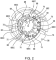
- an exemplary prior art bobbin 58 includes a dissolvable pill 60.
- the bobbin 58 comprises a generally cylindrical wall 66.
- a plurality of arms 68 positioned in a ring centered about and parallel to the longitudinal axis of the bobbin 58, are individually pivotably connected to the rim of the cylindrical wall 66 by a living hinge 70.
- Each of the arms 68 individually include a radial seat 72 extending toward the longitudinal axis of the bobbin 58. Collectively, the individual radial seats 72 form an annular seat having a diameter sized to capture and retain the head 55H of the spring-loaded actuator pin 55, thereby holding the spring-loaded actuator pin 55 back against the force of the spring 57 in a "cocked" position.
- the toroidal pill 60 is positioned between the lumen of the cylindrical wall 66 and the ringed arms 68 to retain the arms 68 in position centered about and parallel to the longitudinal axis of the bobbin 58 such that the annular seat formed by their radial seats 72 maintain the diameter sized to capture and retain the head 55H of the spring-loaded actuator pin 55, thereby holding the spring-loaded actuator pin 55 back against the force of the spring 57 in a "cocked" position.
- each arm 68 may include a buttress 76 extending from the living-hinge end of the arm 68 along a length of the arm 68.
- the buttress 76 provides additional rigidity to the arm 68 and, during assembly, serves to limit the distance the pill 60 is pushed onto the length of the ringed arms 68.
- each of the arms 68 may include a chamfered end 68CC to facilitate automatic centering and pushing of the pill 60 onto the ringed arms 68.
- the ringed arms 68 are allowed to flex radially outwardly individually via their respective living hinge 70 under the pressure of the spring-loaded actuator pin head 55H. As they flex outwardly, their radial seats 72 spread apart until they reach an increased diameter that they no longer form an annular seat for the head 55H of the actuator pin 55, whereupon the head 55H of the spring-loaded actuator pin 55 is released and moves forcibly under the force of the spring 57 to actuate the pierce pin 20 via the transfer pin 46 (i.e., the actuator 10 is automatically "fired").
- the pill 60 must have sufficient strength to hold the arms 68 in their parallel position to hold-back spring-loaded actuator pin 55 and yet must be dissolvable once exposed to water to allow the arms 68 to flex radially outwardly and allow the actuator pin 55 to fire.
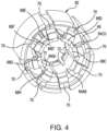
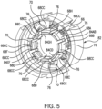
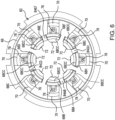
- the bobbin 82 of the present invention is illustrated in Figs. 4-9 .
- the bobbin 82 of the present invention includes components similar to those of the prior art bobbin 58. Accordingly, for uniformity and clarity, in Figs. 4-9 , the same reference numerals used in connection with the prior art bobbin 58 are used when describing the bobbin 82 of the present invention.
- the bobbin 82 of the present invention comprises a generally cylindrical wall 66 having a plurality of arms 68 pivotably connected to the rim of the cylindrical wall 66 by a living hinge 70 to extend into the cylindrical wall 66 and positioned in a ring centered about and parallel to the longitudinal axis of the bobbin 58 such that their respective radial seats 72 form an annular seat having a diameter sized to capture and retain the head 55H of the spring-loaded actuator pin 55, thereby holding the spring-loaded actuator pin 55 back against the force of the spring 57 in a "cocked" position.
- the arms 68 are grouped in pairs and the two arms 68 of each pair are interconnected to each other by a web 84.
- the paired arms 68 interconnected by the web 84 pivot outwardly via their respective living hinges 70 in unison, rather than individually as in the case of the prior art.
- a bobbin 82 having eight arms 68A-68H preferably, adjacent arms 68A & 68B, 68C & 68D, 68E & 68F and 68G & 68H are paired and interconnected by their respective webs 84AB, 84CD, 84EF and 84GH.
- other pairing arrangements may be desired as noted above in the summary of the invention.
- Each of the interconnecting webs (e.g., shown in Fig 9 as 84AB) preferably extends integrally between adjacent arms (e.g., shown in Fig 9 as 68A & 68B) approximately equal to the height of the buttresses 76.
- Each interconnecting web 84 is also preferably thin in structure but arcuately curved to match the outward curvature of the ringed arms 68. Also, all of the components of the bobbin 82 including the interconnecting webs 84 are preferably integrally molded.
- the webbed, interconnected arms 68 of the present invention have significantly increased the ability of the pill 60 to be humidity resistant yet quickly dissolvable in cold water.
Landscapes
- Engineering & Computer Science (AREA)
- Mechanical Engineering (AREA)
- Ocean & Marine Engineering (AREA)
- Air Bags (AREA)
Claims (10)
- Spulenanordnung für eine automatische Aufblaseinrichtung, umfassend in Kombination:eine allgemein zylindrische Wand (66);eine Vielzahl von Armen (68), die in einem Ring angeordnet sind, der um eine Längsachse der Spule zentriert und parallel dazu ist, wobei j eder Arm durch ein Filmscharnier (70) schwenkbar mit einem Rand der zylindrischen Wand verbunden ist,wobei mindestens einer der Arme einen radialen Sitz (72) beinhaltet, der sich in Richtung der Längsachse der Spule erstreckt, um einen ringförmigen Sitz zu bilden, der einen Durchmesser aufweist, um einen Kopf (55H) eines federbelasteten Betätigungsstifts der automatischen Aufblaseinrichtung zu halten, um den federbelasteten Betätigungsstift in einer "gespannten" Position zu halten,eine ringförmige Pille (60), die zwischen einem Lumen der zylindrischen Wand und den in einem Ring angeordneten Armen positioniert ist, um die Arme in einer Position zu halten, die um die Längsachse der Spule zentriert und parallel dazu ist, sodass der ringförmige Sitz den Durchmesser beibehält, um den Kopf des federbelasteten Betätigungsstifts zu halten, wodurch der federbelastete Betätigungsstift in der "gespannten" Position gehalten wird, undwobei die Pille auflösbar ist, sobald sie Wasser ausgesetzt wird, um zu ermöglichen, dass sich die Arme radial nach außen biegen und den federbelasteten Betätigungsstift freigeben; undeinen Steg, der mindestens ein benachbartes Paar der Arme miteinander verbindet, wobei der Steg es den gepaarten Armen ermöglicht, über ihre jeweiligen Filmscharniere gemeinsam nach außen zu schwenken.
- Spule nach Anspruch 1, wobei mindestens einer der Arme eine Verstrebung beinhaltet, die sich von seinem Filmscharnierende des Arms entlang einer Länge des Arms erstreckt, um dem Arm zusätzliche Steifigkeit bereitzustellen.
- Spule nach Anspruch 2, wobei die Verstrebung den Abstand begrenzt, über den die Pille auf eine Länge der ringförmigen Arme geschoben werden kann.
- Spule nach Anspruch 3, wobei die Arme ein abgeschrägtes Ende beinhalten, um das automatische Zentrieren und Aufschieben der Pille auf die beringten Arme zu erleichtern.
- Spule nach Anspruch 4, wobei, sobald sich die Pille in Wasser auflöst, den ringförmigen Armen ermöglicht ist, sich über ihr jeweiliges Filmscharnier unter dem Druck des federbelasteten Betätigungsstiftkopfs radial nach außen zu biegen, woraufhin sich ihre jeweiligen radialen Sitze auf einen vergrößerten Durchmesser spreizen, der nicht mehr den ringförmigen Sitz für den Kopf des federbelasteten Betätigungsstifts bildet, wodurch der Kopf des federbelasteten Betätigungsstifts freigegeben wird, um die Aufblaseinrichtung zu betätigen.
- Spule nach Anspruch 1, wobei die Pille eine ausreichende Festigkeit aufweist, um die Arme in der parallelen Position zu halten, um den federbelasteten Betätigungsstift zurückzuhalten.
- Spule nach Anspruch 1, die acht Arme beinhaltet, die vier benachbarte, gepaarte Arme bilden, wobei alle gepaarten Arme durch ihre jeweiligen Stege miteinander verbunden sind.
- Spule nach Anspruch 2, wobei sich mindestens einer der Verbindungsstege einstückig zwischen benachbarten Armen erstreckt, die etwa gleich hoch sind wie ihre jeweiligen Verstrebungen.
- Spule nach Anspruch 1, wobei mindestens einer der Stege von dünner Struktur ist und bogenförmig gekrümmt ist, um mit einer äußeren Krümmung der ringförmigen Arme übereinzustimmen.
- Spule nach Anspruch 1, wobei die Spule einstückig geformt ist.
Applications Claiming Priority (3)
| Application Number | Priority Date | Filing Date | Title |
|---|---|---|---|
| US201862653999P | 2018-04-06 | 2018-04-06 | |
| US16/375,256 US10994818B2 (en) | 2018-04-06 | 2019-04-04 | Bobbin for automatic inflator |
| PCT/US2019/025928 WO2019195642A1 (en) | 2018-04-06 | 2019-04-05 | Bobbin for automatic inflator |
Publications (3)
| Publication Number | Publication Date |
|---|---|
| EP3774520A1 EP3774520A1 (de) | 2021-02-17 |
| EP3774520A4 EP3774520A4 (de) | 2022-06-29 |
| EP3774520B1 true EP3774520B1 (de) | 2023-11-29 |
Family
ID=68097831
Family Applications (1)
| Application Number | Title | Priority Date | Filing Date |
|---|---|---|---|
| EP19782052.5A Active EP3774520B1 (de) | 2018-04-06 | 2019-04-05 | Spule für automatische aufblasvorrichtung |
Country Status (6)
| Country | Link |
|---|---|
| US (1) | US10994818B2 (de) |
| EP (1) | EP3774520B1 (de) |
| JP (1) | JP7416714B2 (de) |
| AU (1) | AU2019247846B2 (de) |
| CA (1) | CA3096269A1 (de) |
| WO (1) | WO2019195642A1 (de) |
Families Citing this family (20)
| Publication number | Priority date | Publication date | Assignee | Title |
|---|---|---|---|---|
| US10441761B2 (en) | 2016-07-01 | 2019-10-15 | Boston Scientific Scimed, Inc. | Delivery devices and methods |
| CN115591066A (zh) | 2017-01-10 | 2023-01-13 | 波士顿科学国际有限公司(Us) | 用于输送粉末药剂的装置和方法 |
| US10786596B2 (en) | 2018-01-12 | 2020-09-29 | Boston Scientific Scimed, Inc. | Powder for achieving hemostasis |
| US11766546B2 (en) | 2018-01-31 | 2023-09-26 | Boston Scientific Scimed, Inc. | Apparatuses and methods for delivering powdered agents |
| US11180230B2 (en) * | 2018-06-13 | 2021-11-23 | Halkey-Roberts Corporation | Disposable Inflator |
| WO2019241587A1 (en) * | 2018-06-13 | 2019-12-19 | Halkey-Roberts Corporation | Disposable inflator |
| AU2019352968B2 (en) | 2018-10-02 | 2024-10-31 | Boston Scientific Scimed, Inc. | Devices for fluidization and delivering a powdered agent |
| CN117547720A (zh) | 2018-10-02 | 2024-02-13 | 波士顿科学国际有限公司 | 用于流体化和输送粉状剂的装置 |
| EP4017338B1 (de) | 2019-12-03 | 2024-01-31 | Boston Scientific Scimed, Inc. | Medizinprodukte zur wirkstoffabgabe |
| CN121102700A (zh) | 2019-12-03 | 2025-12-12 | 波士顿科学国际有限公司 | 药剂施用医疗装置 |
| WO2021113324A1 (en) | 2019-12-03 | 2021-06-10 | Boston Scientific Scimed, Inc. | Devices and methods for delivering powdered agents |
| EP4417233A3 (de) | 2019-12-03 | 2024-10-23 | Boston Scientific Scimed, Inc. | Medizinische vorrichtungen zur wirkstofffreisetzung |
| CN114845644A (zh) * | 2019-12-20 | 2022-08-02 | 波士顿科学国际有限公司 | 药剂输送装置 |
| US12102749B2 (en) * | 2020-01-06 | 2024-10-01 | Boston Scientific Scimed, Inc. | Agent delivery systems and methods of using the same |
| CN119971275A (zh) | 2020-01-06 | 2025-05-13 | 波士顿科学国际有限公司 | 用于输送粉末状药剂的装置 |
| US11346690B2 (en) * | 2020-01-10 | 2022-05-31 | Boston Engineering Corporation | Device with water-activated, automatic disconnect |
| US12083216B2 (en) | 2020-02-18 | 2024-09-10 | Boston Scientific Scimed, Inc. | Hemostatic compositions and related methods |
| EP4623837A3 (de) | 2020-03-06 | 2025-12-03 | Boston Scientific Scimed, Inc. | Vorrichtungen zur abgabe von pulverförmigen mitteln |
| JP7665646B2 (ja) | 2020-03-24 | 2025-04-21 | ボストン サイエンティフィック サイムド,インコーポレイテッド | 薬剤送達システム及びその使用方法 |
| KR20230007378A (ko) | 2020-04-17 | 2023-01-12 | 보스톤 싸이엔티픽 싸이메드 인코포레이티드 | 지혈 조성물 및 관련 방법 |
Family Cites Families (32)
| Publication number | Priority date | Publication date | Assignee | Title |
|---|---|---|---|---|
| US3059814A (en) | 1959-11-09 | 1962-10-23 | Eugene E Poncel | Actuator for emergency water equipment |
| US3091782A (en) | 1962-06-11 | 1963-06-04 | Aerotec Ind Inc | Apparatus for flotation of articles on water |
| US3426942A (en) | 1967-07-31 | 1969-02-11 | Jay El Products Inc | Water-responsive energizing apparatus |
| US3579964A (en) | 1969-07-01 | 1971-05-25 | Us Navy | Squib-powered automatic inflation device |
| GB1360212A (en) | 1970-12-21 | 1974-07-17 | Martin J | Survival or like packs particularly suitable for airmen |
| US3702014A (en) | 1971-02-19 | 1972-11-07 | Us Navy | Squib ejected marker buoy |
| US3809288A (en) | 1973-03-26 | 1974-05-07 | G Mackal | Inflation manifold |
| US3997079A (en) | 1974-04-17 | 1976-12-14 | Wolfgang Niemann | Automatic inflating device for lifesaving devices |
| US3910457A (en) | 1974-05-06 | 1975-10-07 | Koch & Sons Inc H | Electronic water-activated parachute release and life vest inflator |
| US4223805A (en) | 1978-08-04 | 1980-09-23 | Mackal Glenn H | Automatic inflator |
| US4267944A (en) | 1978-08-07 | 1981-05-19 | Mackal Glenn H | Automatic inflator |
| US4260075A (en) * | 1978-08-01 | 1981-04-07 | Mackal Glenn H | Automatic inflator |
| US4382231A (en) | 1980-11-17 | 1983-05-03 | Conax Corporation | Fluid conductivity sensor |
| US4513248A (en) | 1980-11-17 | 1985-04-23 | Conax Corporation | Fluid conductivity sensor |
| US4436159A (en) | 1981-05-01 | 1984-03-13 | Kidde, Inc. | Manual/electric activated squib actuated discharge valve for fire extinguishers |
| US4488546A (en) | 1983-06-23 | 1984-12-18 | Bernhardt Apparatebau Gmbh & Co. | Release mechanism for retention means for oxygen masks |
| US4627823A (en) | 1984-07-23 | 1986-12-09 | Glenn Mackal | Safety latched automatic actuator and throwable personal flotation assembly |
| US5076468A (en) | 1990-02-28 | 1991-12-31 | Halkey-Roberts Corporation | Squib inflator adaptor |
| DE59201404D1 (de) | 1991-09-28 | 1995-03-23 | Bernhardt Apparatebau Gmbh Co | Vorrichtung zum Aufblasen, insbesondere eines Behälters oder eines Schwimmkörpers eines Rettungsgerätes. |
| DE9210848U1 (de) | 1992-08-13 | 1993-12-16 | Bernhardt Apparatebau Gmbh + Co., 22880 Wedel | Vorrichtung zum Aufblasen, insbesondere eines Behälters oder eines Schwimmkörpers eines Rettungsgerätes |
| DE9210849U1 (de) | 1992-08-13 | 1993-12-16 | Bernhardt Apparatebau GmbH & Co., 22880 Wedel | Anzeigeeinrichtung für eine Vorrichtung zum Aufblasen, insbesondere eines Behälters oder eines Schwimmkörpers eines Rettungsgerätes |
| DE19503806A1 (de) | 1994-02-11 | 1995-08-17 | Bernhardt Apparatebau Gmbh Co | Vorrichtung zum Aufblasen eines Behälters oder eines Schwimmkörpers, insbesondere einer Schwimmweste |
| US5694986A (en) | 1995-02-07 | 1997-12-09 | Halkey-Roberts Corporation | Automatic actuator with apertured housing and safety indicator |
| US5601124A (en) | 1995-02-07 | 1997-02-11 | Halkey-Roberts Corporation | Autoinflator with apertured housing |
| US6705488B2 (en) | 2001-09-07 | 2004-03-16 | Halkey-Roberts Corporation | Bobbin for automatic inflator |
| US7357689B2 (en) * | 2005-01-19 | 2008-04-15 | Campbell Richard A | Automatic inflation device having a moisture activated trigger and release system with reduced force applied to the degradable element |
| AU2010236290B2 (en) * | 2009-04-15 | 2015-07-16 | Halkey-Roberts Corporation | Manual inflator with cylinder connector and status indicator |
| US8353736B2 (en) * | 2010-07-30 | 2013-01-15 | Hudson Wang | Double point indicating auto/manual gas inflator |
| GB2485379B (en) * | 2010-11-11 | 2012-12-26 | United Moulders Ltd | Inflation device mechanism |
| CA2873813A1 (en) * | 2012-05-16 | 2013-11-21 | Halkey-Roberts Corporation | Inflator |
| KR101378269B1 (ko) * | 2012-07-09 | 2014-03-24 | 주식회사 만투 | 보빈 및 이를 사용한 수중용 자동격발장치 |
| US9365270B2 (en) * | 2014-02-11 | 2016-06-14 | William Lee | Inflator |
-
2019
- 2019-04-04 US US16/375,256 patent/US10994818B2/en active Active
- 2019-04-05 WO PCT/US2019/025928 patent/WO2019195642A1/en not_active Ceased
- 2019-04-05 AU AU2019247846A patent/AU2019247846B2/en active Active
- 2019-04-05 JP JP2020554454A patent/JP7416714B2/ja active Active
- 2019-04-05 CA CA3096269A patent/CA3096269A1/en active Pending
- 2019-04-05 EP EP19782052.5A patent/EP3774520B1/de active Active
Also Published As
| Publication number | Publication date |
|---|---|
| EP3774520A4 (de) | 2022-06-29 |
| AU2019247846B2 (en) | 2025-04-24 |
| CA3096269A1 (en) | 2019-10-10 |
| JP2021521043A (ja) | 2021-08-26 |
| US10994818B2 (en) | 2021-05-04 |
| AU2019247846A1 (en) | 2020-10-29 |
| NZ768886A (en) | 2025-03-28 |
| US20190308701A1 (en) | 2019-10-10 |
| WO2019195642A1 (en) | 2019-10-10 |
| JP7416714B2 (ja) | 2024-01-17 |
| EP3774520A1 (de) | 2021-02-17 |
Similar Documents
| Publication | Publication Date | Title |
|---|---|---|
| EP3774520B1 (de) | Spule für automatische aufblasvorrichtung | |
| US6705488B2 (en) | Bobbin for automatic inflator | |
| AU2009200406B2 (en) | Automatic inflator with status indicator | |
| US8360276B2 (en) | Manual inflator with cylinder connector and status indicator | |
| US9517976B2 (en) | Inflator | |
| AU2002341594A1 (en) | Bobbin for automatic inflator | |
| US5601124A (en) | Autoinflator with apertured housing | |
| US7819714B2 (en) | Water activated inflator for inflatable device and method of air deployment | |
| US5694986A (en) | Automatic actuator with apertured housing and safety indicator | |
| CN108750124A (zh) | 遇水自动充气装置及无人机 | |
| KR101680700B1 (ko) | 휴대용 투척식 구명 장치 | |
| AU2005237664B2 (en) | Water activated inflator for inflatable device and method of air deployment | |
| US7357689B2 (en) | Automatic inflation device having a moisture activated trigger and release system with reduced force applied to the degradable element | |
| AU2023208661A1 (en) | Automatic inflator with bobbin employing an electronic pill | |
| KR101378269B1 (ko) | 보빈 및 이를 사용한 수중용 자동격발장치 | |
| WO2012027244A1 (en) | Apparatus and method for universally mounting an inflator, exhaust valve or relief valve interiorly of an inflatable article | |
| AU2002332819A1 (en) | Automatic inflator with status indicator | |
| HK1167375A (en) | Manual inflator with cylinder connector and status indicator |
Legal Events
| Date | Code | Title | Description |
|---|---|---|---|
| STAA | Information on the status of an ep patent application or granted ep patent |
Free format text: STATUS: THE INTERNATIONAL PUBLICATION HAS BEEN MADE |
|
| PUAI | Public reference made under article 153(3) epc to a published international application that has entered the european phase |
Free format text: ORIGINAL CODE: 0009012 |
|
| STAA | Information on the status of an ep patent application or granted ep patent |
Free format text: STATUS: REQUEST FOR EXAMINATION WAS MADE |
|
| 17P | Request for examination filed |
Effective date: 20201002 |
|
| AK | Designated contracting states |
Kind code of ref document: A1 Designated state(s): AL AT BE BG CH CY CZ DE DK EE ES FI FR GB GR HR HU IE IS IT LI LT LU LV MC MK MT NL NO PL PT RO RS SE SI SK SM TR |
|
| AX | Request for extension of the european patent |
Extension state: BA ME |
|
| DAV | Request for validation of the european patent (deleted) | ||
| DAX | Request for extension of the european patent (deleted) | ||
| A4 | Supplementary search report drawn up and despatched |
Effective date: 20220530 |
|
| RIC1 | Information provided on ipc code assigned before grant |
Ipc: B63C 9/00 20060101ALI20220523BHEP Ipc: B63C 9/18 20060101AFI20220523BHEP |
|
| GRAP | Despatch of communication of intention to grant a patent |
Free format text: ORIGINAL CODE: EPIDOSNIGR1 |
|
| STAA | Information on the status of an ep patent application or granted ep patent |
Free format text: STATUS: GRANT OF PATENT IS INTENDED |
|
| INTG | Intention to grant announced |
Effective date: 20230622 |
|
| GRAS | Grant fee paid |
Free format text: ORIGINAL CODE: EPIDOSNIGR3 |
|
| GRAA | (expected) grant |
Free format text: ORIGINAL CODE: 0009210 |
|
| STAA | Information on the status of an ep patent application or granted ep patent |
Free format text: STATUS: THE PATENT HAS BEEN GRANTED |
|
| AK | Designated contracting states |
Kind code of ref document: B1 Designated state(s): AL AT BE BG CH CY CZ DE DK EE ES FI FR GB GR HR HU IE IS IT LI LT LU LV MC MK MT NL NO PL PT RO RS SE SI SK SM TR |
|
| REG | Reference to a national code |
Ref country code: GB Ref legal event code: FG4D |
|
| REG | Reference to a national code |
Ref country code: CH Ref legal event code: EP |
|
| REG | Reference to a national code |
Ref country code: DE Ref legal event code: R096 Ref document number: 602019042441 Country of ref document: DE |
|
| REG | Reference to a national code |
Ref country code: IE Ref legal event code: FG4D |
|
| REG | Reference to a national code |
Ref country code: LT Ref legal event code: MG9D |
|
| REG | Reference to a national code |
Ref country code: NL Ref legal event code: MP Effective date: 20231129 |
|
| PG25 | Lapsed in a contracting state [announced via postgrant information from national office to epo] |
Ref country code: GR Free format text: LAPSE BECAUSE OF FAILURE TO SUBMIT A TRANSLATION OF THE DESCRIPTION OR TO PAY THE FEE WITHIN THE PRESCRIBED TIME-LIMIT Effective date: 20240301 |
|
| PG25 | Lapsed in a contracting state [announced via postgrant information from national office to epo] |
Ref country code: IS Free format text: LAPSE BECAUSE OF FAILURE TO SUBMIT A TRANSLATION OF THE DESCRIPTION OR TO PAY THE FEE WITHIN THE PRESCRIBED TIME-LIMIT Effective date: 20240329 |
|
| PG25 | Lapsed in a contracting state [announced via postgrant information from national office to epo] |
Ref country code: LT Free format text: LAPSE BECAUSE OF FAILURE TO SUBMIT A TRANSLATION OF THE DESCRIPTION OR TO PAY THE FEE WITHIN THE PRESCRIBED TIME-LIMIT Effective date: 20231129 |
|
| PG25 | Lapsed in a contracting state [announced via postgrant information from national office to epo] |
Ref country code: ES Free format text: LAPSE BECAUSE OF FAILURE TO SUBMIT A TRANSLATION OF THE DESCRIPTION OR TO PAY THE FEE WITHIN THE PRESCRIBED TIME-LIMIT Effective date: 20231129 |
|
| PG25 | Lapsed in a contracting state [announced via postgrant information from national office to epo] |
Ref country code: LT Free format text: LAPSE BECAUSE OF FAILURE TO SUBMIT A TRANSLATION OF THE DESCRIPTION OR TO PAY THE FEE WITHIN THE PRESCRIBED TIME-LIMIT Effective date: 20231129 Ref country code: IS Free format text: LAPSE BECAUSE OF FAILURE TO SUBMIT A TRANSLATION OF THE DESCRIPTION OR TO PAY THE FEE WITHIN THE PRESCRIBED TIME-LIMIT Effective date: 20240329 Ref country code: GR Free format text: LAPSE BECAUSE OF FAILURE TO SUBMIT A TRANSLATION OF THE DESCRIPTION OR TO PAY THE FEE WITHIN THE PRESCRIBED TIME-LIMIT Effective date: 20240301 Ref country code: ES Free format text: LAPSE BECAUSE OF FAILURE TO SUBMIT A TRANSLATION OF THE DESCRIPTION OR TO PAY THE FEE WITHIN THE PRESCRIBED TIME-LIMIT Effective date: 20231129 Ref country code: BG Free format text: LAPSE BECAUSE OF FAILURE TO SUBMIT A TRANSLATION OF THE DESCRIPTION OR TO PAY THE FEE WITHIN THE PRESCRIBED TIME-LIMIT Effective date: 20240229 |
|
| REG | Reference to a national code |
Ref country code: AT Ref legal event code: MK05 Ref document number: 1635867 Country of ref document: AT Kind code of ref document: T Effective date: 20231129 |
|
| PG25 | Lapsed in a contracting state [announced via postgrant information from national office to epo] |
Ref country code: NL Free format text: LAPSE BECAUSE OF FAILURE TO SUBMIT A TRANSLATION OF THE DESCRIPTION OR TO PAY THE FEE WITHIN THE PRESCRIBED TIME-LIMIT Effective date: 20231129 |
|
| PG25 | Lapsed in a contracting state [announced via postgrant information from national office to epo] |
Ref country code: SE Free format text: LAPSE BECAUSE OF FAILURE TO SUBMIT A TRANSLATION OF THE DESCRIPTION OR TO PAY THE FEE WITHIN THE PRESCRIBED TIME-LIMIT Effective date: 20231129 Ref country code: RS Free format text: LAPSE BECAUSE OF FAILURE TO SUBMIT A TRANSLATION OF THE DESCRIPTION OR TO PAY THE FEE WITHIN THE PRESCRIBED TIME-LIMIT Effective date: 20231129 Ref country code: PL Free format text: LAPSE BECAUSE OF FAILURE TO SUBMIT A TRANSLATION OF THE DESCRIPTION OR TO PAY THE FEE WITHIN THE PRESCRIBED TIME-LIMIT Effective date: 20231129 Ref country code: NO Free format text: LAPSE BECAUSE OF FAILURE TO SUBMIT A TRANSLATION OF THE DESCRIPTION OR TO PAY THE FEE WITHIN THE PRESCRIBED TIME-LIMIT Effective date: 20240229 Ref country code: NL Free format text: LAPSE BECAUSE OF FAILURE TO SUBMIT A TRANSLATION OF THE DESCRIPTION OR TO PAY THE FEE WITHIN THE PRESCRIBED TIME-LIMIT Effective date: 20231129 Ref country code: LV Free format text: LAPSE BECAUSE OF FAILURE TO SUBMIT A TRANSLATION OF THE DESCRIPTION OR TO PAY THE FEE WITHIN THE PRESCRIBED TIME-LIMIT Effective date: 20231129 Ref country code: HR Free format text: LAPSE BECAUSE OF FAILURE TO SUBMIT A TRANSLATION OF THE DESCRIPTION OR TO PAY THE FEE WITHIN THE PRESCRIBED TIME-LIMIT Effective date: 20231129 |
|
| PG25 | Lapsed in a contracting state [announced via postgrant information from national office to epo] |
Ref country code: DK Free format text: LAPSE BECAUSE OF FAILURE TO SUBMIT A TRANSLATION OF THE DESCRIPTION OR TO PAY THE FEE WITHIN THE PRESCRIBED TIME-LIMIT Effective date: 20231129 |
|
| PG25 | Lapsed in a contracting state [announced via postgrant information from national office to epo] |
Ref country code: CZ Free format text: LAPSE BECAUSE OF FAILURE TO SUBMIT A TRANSLATION OF THE DESCRIPTION OR TO PAY THE FEE WITHIN THE PRESCRIBED TIME-LIMIT Effective date: 20231129 Ref country code: AT Free format text: LAPSE BECAUSE OF FAILURE TO SUBMIT A TRANSLATION OF THE DESCRIPTION OR TO PAY THE FEE WITHIN THE PRESCRIBED TIME-LIMIT Effective date: 20231129 |
|
| PG25 | Lapsed in a contracting state [announced via postgrant information from national office to epo] |
Ref country code: SK Free format text: LAPSE BECAUSE OF FAILURE TO SUBMIT A TRANSLATION OF THE DESCRIPTION OR TO PAY THE FEE WITHIN THE PRESCRIBED TIME-LIMIT Effective date: 20231129 |
|
| PG25 | Lapsed in a contracting state [announced via postgrant information from national office to epo] |
Ref country code: SM Free format text: LAPSE BECAUSE OF FAILURE TO SUBMIT A TRANSLATION OF THE DESCRIPTION OR TO PAY THE FEE WITHIN THE PRESCRIBED TIME-LIMIT Effective date: 20231129 Ref country code: SK Free format text: LAPSE BECAUSE OF FAILURE TO SUBMIT A TRANSLATION OF THE DESCRIPTION OR TO PAY THE FEE WITHIN THE PRESCRIBED TIME-LIMIT Effective date: 20231129 Ref country code: RO Free format text: LAPSE BECAUSE OF FAILURE TO SUBMIT A TRANSLATION OF THE DESCRIPTION OR TO PAY THE FEE WITHIN THE PRESCRIBED TIME-LIMIT Effective date: 20231129 Ref country code: EE Free format text: LAPSE BECAUSE OF FAILURE TO SUBMIT A TRANSLATION OF THE DESCRIPTION OR TO PAY THE FEE WITHIN THE PRESCRIBED TIME-LIMIT Effective date: 20231129 Ref country code: DK Free format text: LAPSE BECAUSE OF FAILURE TO SUBMIT A TRANSLATION OF THE DESCRIPTION OR TO PAY THE FEE WITHIN THE PRESCRIBED TIME-LIMIT Effective date: 20231129 Ref country code: CZ Free format text: LAPSE BECAUSE OF FAILURE TO SUBMIT A TRANSLATION OF THE DESCRIPTION OR TO PAY THE FEE WITHIN THE PRESCRIBED TIME-LIMIT Effective date: 20231129 Ref country code: AT Free format text: LAPSE BECAUSE OF FAILURE TO SUBMIT A TRANSLATION OF THE DESCRIPTION OR TO PAY THE FEE WITHIN THE PRESCRIBED TIME-LIMIT Effective date: 20231129 |
|
| PG25 | Lapsed in a contracting state [announced via postgrant information from national office to epo] |
Ref country code: PT Free format text: LAPSE BECAUSE OF FAILURE TO SUBMIT A TRANSLATION OF THE DESCRIPTION OR TO PAY THE FEE WITHIN THE PRESCRIBED TIME-LIMIT Effective date: 20240401 |
|
| PG25 | Lapsed in a contracting state [announced via postgrant information from national office to epo] |
Ref country code: PT Free format text: LAPSE BECAUSE OF FAILURE TO SUBMIT A TRANSLATION OF THE DESCRIPTION OR TO PAY THE FEE WITHIN THE PRESCRIBED TIME-LIMIT Effective date: 20240401 |
|
| REG | Reference to a national code |
Ref country code: DE Ref legal event code: R097 Ref document number: 602019042441 Country of ref document: DE |
|
| PLBE | No opposition filed within time limit |
Free format text: ORIGINAL CODE: 0009261 |
|
| STAA | Information on the status of an ep patent application or granted ep patent |
Free format text: STATUS: NO OPPOSITION FILED WITHIN TIME LIMIT |
|
| PG25 | Lapsed in a contracting state [announced via postgrant information from national office to epo] |
Ref country code: SI Free format text: LAPSE BECAUSE OF FAILURE TO SUBMIT A TRANSLATION OF THE DESCRIPTION OR TO PAY THE FEE WITHIN THE PRESCRIBED TIME-LIMIT Effective date: 20231129 |
|
| PG25 | Lapsed in a contracting state [announced via postgrant information from national office to epo] |
Ref country code: SI Free format text: LAPSE BECAUSE OF FAILURE TO SUBMIT A TRANSLATION OF THE DESCRIPTION OR TO PAY THE FEE WITHIN THE PRESCRIBED TIME-LIMIT Effective date: 20231129 |
|
| 26N | No opposition filed |
Effective date: 20240830 |
|
| PG25 | Lapsed in a contracting state [announced via postgrant information from national office to epo] |
Ref country code: MC Free format text: LAPSE BECAUSE OF FAILURE TO SUBMIT A TRANSLATION OF THE DESCRIPTION OR TO PAY THE FEE WITHIN THE PRESCRIBED TIME-LIMIT Effective date: 20231129 |
|
| PG25 | Lapsed in a contracting state [announced via postgrant information from national office to epo] |
Ref country code: MC Free format text: LAPSE BECAUSE OF FAILURE TO SUBMIT A TRANSLATION OF THE DESCRIPTION OR TO PAY THE FEE WITHIN THE PRESCRIBED TIME-LIMIT Effective date: 20231129 |
|
| REG | Reference to a national code |
Ref country code: CH Ref legal event code: PL |
|
| PG25 | Lapsed in a contracting state [announced via postgrant information from national office to epo] |
Ref country code: LU Free format text: LAPSE BECAUSE OF NON-PAYMENT OF DUE FEES Effective date: 20240405 |
|
| REG | Reference to a national code |
Ref country code: BE Ref legal event code: MM Effective date: 20240430 |
|
| PG25 | Lapsed in a contracting state [announced via postgrant information from national office to epo] |
Ref country code: LU Free format text: LAPSE BECAUSE OF NON-PAYMENT OF DUE FEES Effective date: 20240405 |
|
| PG25 | Lapsed in a contracting state [announced via postgrant information from national office to epo] |
Ref country code: BE Free format text: LAPSE BECAUSE OF NON-PAYMENT OF DUE FEES Effective date: 20240430 |
|
| PG25 | Lapsed in a contracting state [announced via postgrant information from national office to epo] |
Ref country code: BE Free format text: LAPSE BECAUSE OF NON-PAYMENT OF DUE FEES Effective date: 20240430 Ref country code: CH Free format text: LAPSE BECAUSE OF NON-PAYMENT OF DUE FEES Effective date: 20240430 |
|
| PGFP | Annual fee paid to national office [announced via postgrant information from national office to epo] |
Ref country code: DE Payment date: 20250422 Year of fee payment: 7 |
|
| PGFP | Annual fee paid to national office [announced via postgrant information from national office to epo] |
Ref country code: GB Payment date: 20250423 Year of fee payment: 7 |
|
| PGFP | Annual fee paid to national office [announced via postgrant information from national office to epo] |
Ref country code: IT Payment date: 20250424 Year of fee payment: 7 |
|
| PGFP | Annual fee paid to national office [announced via postgrant information from national office to epo] |
Ref country code: FR Payment date: 20250425 Year of fee payment: 7 |
|
| PGFP | Annual fee paid to national office [announced via postgrant information from national office to epo] |
Ref country code: IE Payment date: 20250422 Year of fee payment: 7 |
|
| PG25 | Lapsed in a contracting state [announced via postgrant information from national office to epo] |
Ref country code: CY Free format text: LAPSE BECAUSE OF FAILURE TO SUBMIT A TRANSLATION OF THE DESCRIPTION OR TO PAY THE FEE WITHIN THE PRESCRIBED TIME-LIMIT; INVALID AB INITIO Effective date: 20190405 |
|
| PG25 | Lapsed in a contracting state [announced via postgrant information from national office to epo] |
Ref country code: HU Free format text: LAPSE BECAUSE OF FAILURE TO SUBMIT A TRANSLATION OF THE DESCRIPTION OR TO PAY THE FEE WITHIN THE PRESCRIBED TIME-LIMIT; INVALID AB INITIO Effective date: 20190405 |
|
| PG25 | Lapsed in a contracting state [announced via postgrant information from national office to epo] |
Ref country code: FI Free format text: LAPSE BECAUSE OF FAILURE TO SUBMIT A TRANSLATION OF THE DESCRIPTION OR TO PAY THE FEE WITHIN THE PRESCRIBED TIME-LIMIT Effective date: 20231129 |