EP3774515B1 - Rope-handling system, special purpose craft, use of the rope-handling system and guiding pole - Google Patents
Rope-handling system, special purpose craft, use of the rope-handling system and guiding pole Download PDFInfo
- Publication number
- EP3774515B1 EP3774515B1 EP19778259.2A EP19778259A EP3774515B1 EP 3774515 B1 EP3774515 B1 EP 3774515B1 EP 19778259 A EP19778259 A EP 19778259A EP 3774515 B1 EP3774515 B1 EP 3774515B1
- Authority
- EP
- European Patent Office
- Prior art keywords
- guiding pole
- line
- rope
- special purpose
- guiding
- Prior art date
- Legal status (The legal status is an assumption and is not a legal conclusion. Google has not performed a legal analysis and makes no representation as to the accuracy of the status listed.)
- Active
Links
Images


Classifications
-
- B—PERFORMING OPERATIONS; TRANSPORTING
- B63—SHIPS OR OTHER WATERBORNE VESSELS; RELATED EQUIPMENT
- B63B—SHIPS OR OTHER WATERBORNE VESSELS; EQUIPMENT FOR SHIPPING
- B63B21/00—Tying-up; Shifting, towing, or pushing equipment; Anchoring
- B63B21/04—Fastening or guiding equipment for chains, ropes, hawsers, or the like
-
- B—PERFORMING OPERATIONS; TRANSPORTING
- B63—SHIPS OR OTHER WATERBORNE VESSELS; RELATED EQUIPMENT
- B63B—SHIPS OR OTHER WATERBORNE VESSELS; EQUIPMENT FOR SHIPPING
- B63B21/00—Tying-up; Shifting, towing, or pushing equipment; Anchoring
- B63B21/54—Boat-hooks or the like, e.g. hooks detachably mounted to a pole
-
- B—PERFORMING OPERATIONS; TRANSPORTING
- B63—SHIPS OR OTHER WATERBORNE VESSELS; RELATED EQUIPMENT
- B63B—SHIPS OR OTHER WATERBORNE VESSELS; EQUIPMENT FOR SHIPPING
- B63B21/00—Tying-up; Shifting, towing, or pushing equipment; Anchoring
- B63B21/56—Towing or pushing equipment
-
- B—PERFORMING OPERATIONS; TRANSPORTING
- B63—SHIPS OR OTHER WATERBORNE VESSELS; RELATED EQUIPMENT
- B63B—SHIPS OR OTHER WATERBORNE VESSELS; EQUIPMENT FOR SHIPPING
- B63B21/00—Tying-up; Shifting, towing, or pushing equipment; Anchoring
- B63B21/56—Towing or pushing equipment
- B63B21/58—Adaptations of hooks for towing; Towing-hook mountings
-
- B—PERFORMING OPERATIONS; TRANSPORTING
- B63—SHIPS OR OTHER WATERBORNE VESSELS; RELATED EQUIPMENT
- B63B—SHIPS OR OTHER WATERBORNE VESSELS; EQUIPMENT FOR SHIPPING
- B63B35/00—Vessels or similar floating structures specially adapted for specific purposes and not otherwise provided for
- B63B35/66—Tugs
- B63B35/68—Tugs for towing
-
- B—PERFORMING OPERATIONS; TRANSPORTING
- B66—HOISTING; LIFTING; HAULING
- B66D—CAPSTANS; WINCHES; TACKLES, e.g. PULLEY BLOCKS; HOISTS
- B66D3/00—Portable or mobile lifting or hauling appliances
- B66D3/006—Power actuated devices operating on ropes, cables, or chains for hauling in a mainly horizontal direction
-
- E—FIXED CONSTRUCTIONS
- E02—HYDRAULIC ENGINEERING; FOUNDATIONS; SOIL SHIFTING
- E02B—HYDRAULIC ENGINEERING
- E02B3/00—Engineering works in connection with control or use of streams, rivers, coasts, or other marine sites; Sealings or joints for engineering works in general
- E02B3/20—Equipment for shipping on coasts, in harbours or on other fixed marine structures, e.g. bollards
- E02B3/24—Mooring posts
-
- B—PERFORMING OPERATIONS; TRANSPORTING
- B63—SHIPS OR OTHER WATERBORNE VESSELS; RELATED EQUIPMENT
- B63B—SHIPS OR OTHER WATERBORNE VESSELS; EQUIPMENT FOR SHIPPING
- B63B21/00—Tying-up; Shifting, towing, or pushing equipment; Anchoring
- B63B2021/003—Mooring or anchoring equipment, not otherwise provided for
Definitions
- the current disclosure relates to a rope handling system, to a special purpose craft and to a guiding pole.
- Special purpose crafts may be used for various tasks on sea, in harbors, as well as in inland waters.
- tugboats are used for assisting other vessels in various situations, typically requiring maneuvering in restricted waters.
- Tugboats can either tow the assisted vessel or push it.
- the length of the towline may be regulated by a towing winch on the tugboat.
- the towline is connected to a bollard on the assisted vessel.
- the tasks performed by special purpose crafts may range from ice breaking to waterway maintenance, including various situations that might necessitate the attachment of a vessel to another through a rope.
- a similar system can also be used for mooring a vessel at a berth.
- the usual manner to connect a vessel to a special purpose craft or to a berth is to throw a heaving line from the vessel being attached on the deck of the special purpose craft or on the berth, respectively.
- a crew member on the special purpose craft then picks the heaving line and ties it to an end of the towline.
- the heaving line and the connected towline are then heaved to the vessel, released from each other, and the towline is secured to a bollard or other structures of the vessel.
- the heaving line may already be connected to a mooring line of the vessel, and a member of the mooring crew, also called a linesman, picks the heaving line and heaves the mooring line, along with the heaving line, to berth. Then, the heaving line is released form the mooring line, and the mooring line is secured to a bollard or other structures of the berth.
- the manual arrangement has drawbacks, for example that a crew member is needed to be present on the deck of the special purpose craft. In harsh weather, the working conditions can be uncomfortable, or even hazardous. Additionally, the heaving line has a weight attached to its end to facilitate throwing, and being hit by the weight can injure a person on deck or on berth.
- Document WO2017/167892 discloses a tugboat comprising a crane or a robot arm for handling a towing line, the crane or robot arm being provided with a grasping tool for grasping a towing line.
- Document US 2006/0102060 A1 relates to an automatic system for taking up and handling a connecting towrope between a tugboat and a towed vessel.
- the system comprises a fastening carriage which moves on guides around the deck of the tugboat.
- US 6 508 190 B1 discloses a remotely operable device enabling one person to attach and release a boat to and from a mooring.
- GB 1 495 040 A concerns a system for engaging a mooring position in a body of water to a vessel.
- the system comprises a connecting hawser and a catch mechanism.
- EP 3 713 826A1 discloses a tugboat comprising a hull and a line handling system comprising a line guide mechanism.
- a rope-handling system is configured for catching a heaving line and characterized in that it comprises a guiding pole that is convertible between an operating configuration and a storage configuration, the guiding pole comprising pivotable arms forming a Y fork at an upper end of the guiding pole in the operating configuration of the guiding pole, a leg portion forming the upper end of the guiding pole, the arms being attached to the upper end of the pole opposite to each other wherein the arms extend in the same direction with the leg portion in the storage configuration and open away from each other when the guiding pole is converted to the operating configuration.
- the guiding pole further comprises line-engaging means releasably attachable at the base of the arms and connectable to an attachment rope.
- the line-engaging means comprises a line trap for catching a monkey-fist of the heaving line when the heaving line is directed between the arms of the Y fork from another vessel.
- the special purpose craft according to the current disclosure is characterized in that it comprises a rope-handling system according to the current disclosure.
- a rope-handling system is disclosed.
- a special purpose craft comprising the automatic rope-handling system according to the present disclosure is disclosed.
- use of the rope-handling system for attaching a vessel to a special purpose craft or to a land structure is disclosed.
- a guiding pole for catching a heaving line is disclosed.
- the guiding pole according to the present disclosure is characterized in that the guiding pole is convertible between an operating configuration and a storage configuration.
- the guiding pole comprises pivotable arms forming a Y fork in the operating configuration of the guiding pole; and a structure for releasably attaching a line-engaging means configured to catch a monkey-fist at the base of the arms.
- the rope-handling system is characterized in that it comprises a guiding pole that is convertible between an operating configuration and a storage configuration, the guiding pole comprising pivotable arms forming a Y fork in the operating configuration of the guiding pole.
- the arms are typically mounted at the end of the guiding pole which is designed to be the upper end in use.
- the rope-handling system further comprises line-engaging means releasably attachable at the base of the arms and connectable to an attachment rope, wherein the line-engaging means comprises a line trap for catching a monkey-fist of a heaving line when the heaving line is directed between the arms of the Y fork from a vessel.
- the rope-handling system may remove or reduce the need of a crew member on the deck of the special purpose craft when a vessel is being connected by an attachment rope.
- the rope-handling system is designed to catch the heaving line thrown from the vessel by the Y fork of the guiding pole. The Y fork is thus positioned so that it can catch the heaving line.
- a heaving line is a line or a suitable rope thrown from a vessel to another vessel or to land in order to move a rope (such as a towline or a mooring line) between the vessels or between land and a vessel.
- the rope is attached to the heaving line, and the heaving line is heaved to the direction in which the rope is meant to be moved. Oftentimes, and attachment rope is retrieved with the help of a heaving line.
- the structure and positioning of the line-engaging means may further allow connecting the attachment rope with the heaving line without further devices or manual steps.
- the mooring line may first be attached to the heaving line. This attachment is done suitably far away from the end with the monkey-fist, so that the monkey-fist can be flung to the Y fork on land.
- the attachment of the mooring line can take place at the opposite end of the heaving line from the monkey-fist.
- the heaving line may be released from the line-engaging means to be heaved to land.
- the line-engaging means is not attached to an attachment rope on the land side.
- a winch may be used to reel in the heaving line.
- the mooring line would then be positioned suitably for being attached to a bollard or the like.
- the system may comprise a winch with an attachment rope to reel in the heaving line.
- the winch may be suitably configured to take in the line-engaging means and a length of the heaving line.
- One of the advantages of the current system and the special purpose craft is that hazards relating to connecting a vessel to another vessel or to land structures may be reduced.
- the line-engaging means could hit a person catching the heaving line, exposing such persons to injury.
- the weather conditions may make the deck an unstable working area, adding to the hazards.
- a further advantage of the system and its use is that many types of vessels can be connected with it. No modifications are needed on the assisted vessels to improve the efficiency of attachment to a special purpose craft or to a berth.
- vessel or an assisted vessel, is used to describe a seagoing vessel that is attached to a special purpose craft, such as a tugboat, or to land structures, such as a berth.
- attachment rope is used for a towline, or other line used to connect a special purpose craft, for example a tug, with an assisted vessel, and for a mooring line used for connecting a vessel to land structures.
- the guiding pole being convertible between storage configuration and an operating configuration is meant that the guiding pole can be repeatedly transferred between the storage configuration and the operating configuration.
- the current rope-handling system may be used by first extending or pivoting the guiding pole to a sufficient height and opening the arms of the Y fork.
- the line-engaging means is positioned at the base of the arms of the guiding pole, and is attached to the attachment rope.
- the monkey-fist of the heaving line will pass through or above the Y fork and the heaving line will land on either of the arms and slide downwards to the base of the arms.
- the monkey-fist at the end of the heaving line will move upwards and be guided to enter the line trap of the line-engaging means.
- the line-engaging means is releasably attached to the Y fork so that when the heaving line is pulled further, the line-engaging means becomes disconnected from the guiding pole and follows the heaving line to the vessel.
- the line-engaging means is released from the guiding pole and, along with the attachment rope attached to it, is pulled to the vessel, where the attachment rope can be attached to the vessel.
- the rope-handling system comprises a guiding pole and line-engaging means, but additional components may be included.
- a winch may be responsible for releasing the attachment rope in order for it to be heaved to the vessel.
- the winch may also reel in the attachment rope to a suitable length for towing or mooring.
- the winch may hold the attachment rope at a desired length during towing or other connection of a special purpose craft and an assisted vessel.
- the winch may reel the attachment rope back to the special purpose craft at the end of towing.
- the winch may be movable or stationary.
- the attachment rope may be detachable from the winch so that a regular bollard may be used for longer-term mooring of the vessel.
- the winch may be covered by a housing which protects the winch.
- One winch may comprise one or two drums. If a winch comprises two drums, each of the drums may be covered by its own housing, or the two drums may share a housing.
- a winch housing may additionally be formed into or comprise structures that help aligning the attachment rope suitably for the other components of the current rope-handling system.
- An attachment rope may also be comprised in the system according to the present disclosure. Many designs for an attachment rope are known to the skilled person, who is able to select a suitably structured attachment rope for different applications.
- An attachment rope typically has a loop or another type of attaching means at its free end to facilitate the attachment of the attachment rope to the vessel being connected to the special purpose craft or to the land structures.
- the deck structures of a special purpose craft may be designed to support, or to co-operate with, the rope handling system according to the present disclosure.
- the main deck may contain support structures for the guiding pole.
- the guiding pole In the operating configuration, the guiding pole extends above a supporting surface.
- the supporting surface means a solid surface surrounding the guiding pole in the operating configuration.
- the guiding pole may be attached to the supporting surface.
- the guiding pole may be attached to other structures, especially structures under the supporting surface.
- the supporting surface may be, for example a deck of a special purpose craft, a winch housing or an extension thereof. Supporting surface can also be a berth, pier or other solid surface available in a harbor or elsewhere on land.
- the guiding pole according to the present disclosure may be retractable/extendable.
- the guiding pole is convertible between the operating configuration and the storage configuration by retracting and extending the guiding pole relative to a supporting surface.
- the guiding pole being retractable/extendable means that that the portion of the guiding pole which makes contact with the heaving line can be moved vertically in relation to the supporting surface between a retracted position and an extended position.
- the complete guiding pole may move, for example if the guiding pole is made of one rigid piece.
- a leg portion of the guiding pole may be rigid.
- the portions of the guiding ole making contact with the heaving line i.e.
- the upper part may move vertically, while some parts of the guiding pole remain stationary.
- the guiding pole may be telescopic. In the extended position, the upper end of the guiding pole is higher than in the retracted position. In the retracted position, the guiding pole may be entirely under the supporting surface. However, in some embodiments, the guiding pole may be designed to remain partially above the supporting surface also in the retracted position. In one embodiment of the system, the guiding pole is retractable completely under the supporting surface.
- the supporting surface may be a deck of a special purpose craft, or a surface of a land structure.
- a deck of the special purpose craft is herein meant the outer surface of the special purpose craft above which other structures such as the deckhouse are positioned.
- the deck may comprise surface on a single height.
- the deck may comprise surfaces on more than one height.
- the overall plane of a deck is typically substantially horizontal, but deviations commonly occur for practical reasons, such as for improving water run-off from the deck.
- the supporting surface may be the surface present in harbor, such as a berth, pier, or the like. It may contain additional structures, for example metal plating, for attaching the guiding pole onto the supporting surface.
- the current system can be used additionally outside of harbors. For example in channels, especially at locks, the current rope-handling system may be utilized. The system can also be used at various smaller-scale landing places where personnel is not necessarily always present.
- the guiding pole is convertible between the operating configuration and the storage configuration by tilting the guiding pole.
- Tilting guiding pole may be advantageous in situations where the space under the supporting surface, especially under the deck of a special purpose craft, is limited. Such situations may arise, for example when the system according to the present disclosure is retrofitted into an existing special purpose craft.
- Designing the railings to contain support structures for the guiding pole may have advantages in tilting embodiments, for example if it is not possible to attach the guiding pole sufficiently rigidly to the support surface or under it.
- Tilting may be effected at the base of the leg portion or above the base.
- the leg portion may comprise more than one tilting position.
- the guiding pole comprises a leg portion with a base end and a distal end, and the pivotable arms are attached to the distal end opposite to each other, and wherein the arms extend in the same direction with the leg portion in the storage configuration, and open away from each other when the guiding pole is converted to the operating configuration.
- the configuration of the guiding pole can be converted from separate controls.
- the controls may be stationary or portable.
- the guiding pole may be converted manually, as the working environment is more sheltered and stable than on a special purpose craft.
- the configuration of the guiding pole is convertible remotely.
- a remotely convertible configuration of the guiding pole is in the current disclosure meant a guiding pole that can be operated from outside the special purpose craft, or through an at least partly wireless system.
- Such an embodiment may be implemented as a part of a remotely controllable special purpose craft, or as a part of an autonomous special purpose craft.
- the special purpose craft according to the present disclosure is remotely-controllable or autonomous.
- the guiding pole according to the present disclosure may comprise a rigid leg portion.
- the guiding pole may comprise metal, such as aluminum or steel. It can also be made at least partly of composite material, such as plastic, plastic composite, carbon fiber etc. It is possible to construct the leg portion and the arms of different materials, each of which may be independently selected from materials having suitable properties.
- the leg portion may be made of metal, such as steel, and the arms may comprise carbon fiber.
- the leg portion may be attached to machinery which allows the guiding pole to be moved upwards and downwards relative to the supporting surface.
- the leg portion may comprise structures that take part in converting the configuration of the guiding pole.
- a rack-and-pinion type of engagement between the guiding pole and the lifting machinery can be envisaged in extendable and retractable embodiments.
- a hinge with a locking mechanism may be present.
- the conversion between an operating configuration and a storage configuration may be implemented with an electric motor, hydraulic system. Also other types of systems are known in the art. An engine on the special purpose craft or a separate motor, such as an electric motor, can be used for powering the conversion of the guiding pole's configuration.
- the lifting machinery may allow turning the guiding pole around its longitudinal axis.
- the lifting machinery itself may be used to turn the guiding pole.
- the guiding pole may be turnable independently of the lifting machinery.
- Such embodiments may be advantageous in facilitating the aiming of the heaving line from the a vessel.
- a turnable guiding pole may be used to position the Y fork suitably relative to the vessel. This may be especially advantageous in stationary embodiments.
- the possibility to turn the guiding pole may have advantages also in embodiments on a special purpose craft. Especially in rough weather, being able to turn the guiding pole in addition to or instead of adjusting the position of the special purpose craft may be useful.
- the leg portion comprises a base end, which is the lower end of the guiding pole when the guiding pole is mounted on the supporting surface.
- the leg portion also comprises a distal end, which is the upper end of the guiding pole when the pole is mounted on the supporting surface.
- the base end When the guiding pole is converted to the operating configuration, the base end may be lifted on the level of the supporting surface or even above it. However, it is possible that the base end remains below the supporting surface even in the operating configuration of guiding pole.
- the level which the base end reaches depends on the specific embodiment in question, for example on the machinery that is used for converting the guiding pole between operating configuration and storage configuration.
- the guiding pole comprises pivotable arms. When the arms pivot away from each other, they form an Y fork. This is referred to as opening of the arms.
- the arms may comprise two ends, an attachment end and a free end. The arms are in contact with the leg portion through the attachment end.
- the arms may be connected to the leg portion through pivoting means.
- the pivoting means may be a hinge that is designed to allow the pivoting of the arms away from each other to a predetermined extend, so that the desired angle of the Y fork is achieved.
- the pivoting means may be a separate or an integral piece of the guiding pole.
- the pivoting means are located at or near the base of the arms, which is the position where the line trap is located.
- the pivoting means may function passively, i.e. so that the weight of the arms causes the opening of the arms.
- the pivoting means may comprise resistance means that contribute to smooth and controlled opening of the arms, avoiding unwantedly fast opening of the arms.
- the pivoting means may alternatively function actively, i.e. so that the arms open and close only when desired. Actively functioning arms open and close independently of the extending and retracting of the guiding pole. Thus in the actively functioning embodiments of the pivoting means the arms may remain closed even when the guiding pole is extended, and open only when the pivoting means are activated. In other words, the operation configuration can be finalized independently of lifting the leg portion.
- each arm may comprise additional components.
- lights can be mounted on the free ends of the arms to improve the visibility of the Y fork under foggy or dark conditions.
- the arms When the arms extend in the same direction as the guiding pole, they form an extension of the leg portion. In other words, they are folded against each other side by side.
- the arms form an Y fork in the operating configuration.
- the angle of the fork may vary, and may be in the range of 50 to 120 degrees. For example, an angle of 60 to 100 degrees, such as 60, 70, 80 or 90 degrees may be used.
- the length of the leg portion, as well as the arms depends on the size and typical use of the system according to the present disclosure. Practical aspects determine the suitable lengths and the ratio between the length of the leg portion and the length of the arms.
- the arms may be of different length.
- the guiding pole may measure 2 - 4 m in height, for example 3 or 3.5 m, in the operating configuration. It is alternatively possible, that the leg portion of the guiding pole measures 2 - 4 m, such as 3 m, in height in the operating configuration.
- the ease of use of the system may benefit from a higher guiding pole, but the space available under or on the supporting surface may limit the dimensions of the guiding pole.
- the guiding pole is mounted on the deck of a special purpose craft.
- the system according to the present disclosure may increase the versatility of such special purpose crafts.
- the system can also be retrofitted to existing crafts, increasing their usability.
- the guiding pole is positioned on the bow side of a towing winch.
- the guiding pole is positioned on the bow side of at least one of them. It may also be possible to position the guiding pole on the bow side of all of the winches.
- a special purpose craft is in this disclosure meant any vessel that may assist other vessels by towing.
- the primary task of the special purpose craft does not necessarily need to be the assistance of other vessels.
- the special purpose craft is a harbor tug, an escort tug, an ocean-going tug, an ice breaker, a supply vessel, an anchor handler or a workboat.
- the special purpose craft according to the present disclosure may have the advantage that while it is capable of automating the connection between the heaving line and the attachment rope, the crowding of the deck is not increased. Therefore, the special purpose craft may be usable for more variable tasks, possibly also involving people, machinery or goods being present on the deck. This is due to the guiding pole being concealed under the deck, or stowed at the side of the deck in the storage configuration. Also, a lowered guiding pole does not hamper the visibility from the bridge of the special purpose craft.
- the guiding pole is mounted on a land structure, such as on a berth. This may improve the efficiency of mooring vessels. Especially at a harbor the number of personnel present may be reduced. Additionally, by suitably positioning more than one of the systems according to the present disclosure, it may be possible to simultaneously attach the vessel at a corresponding number of positions.
- the rope-handling system further comprises line-engaging means.
- the line-engaging means is able to make contact with both the attachment rope and the heaving line.
- the line-engaging means further comprise the elements for positioning it suitably for receiving the heaving line in order to catch it.
- the line-engaging means is releasably attachable to the guiding pole. Since, once landed on the Y fork of the guiding pole, the heaving line slides down on the lowest position between the pivotable arms, i.e. at the base of the arms, this is also a suitable position for the line-engaging means.
- a heaving line is meant a line that is used to retrieve the attachment rope from the special purpose craft or from the berth by flinging it from a vessel.
- the heaving line may comprise weight at the end which is travels to the special purpose craft or to the berth to increase the flight distance and to improve aiming accuracy of the heaving line.
- a throwing weight may be called a monkey-fist.
- the weight can be a ball-like knot of the same name, or any suitably sized and weighted object, such as a sandbag, attached to the end of the heaving line.
- the diameter of a monkey-fist may be 5-15 cm, for example 1-10 cm.
- the line-engaging means comprises a line trap, which is the structure catching the monkey-fist.
- a line trap which is the structure catching the monkey-fist.
- the rope-handling system according to the present disclosure may be usable in a broad range of height difference between special purpose crafts or berths and vessels.
- the heaving line In situations where the heaving line is received by the Y fork from a similar height, the heaving line will run substantially horizontally between the Y fork and the vessel, and the heaving line naturally lies at the base of the Y fork.
- the vessel is a large container ship, for example, the heaving line is thrown from a position that is much higher than the Y fork. In such a situation, the direction of the heaving line when it is being pulled towards the vessel may significantly deviate from horizontal, and even approach vertical.
- adjusting the distance between the Y fork and the vessel may be used to adjust the running direction of the heaving line.
- the height of the leg portion or the angle between the arms of the guiding pole may be adjusted.
- the shape of the line trap can be adjusted so that the angle of the heaving line can be taken into account.
- the line trap may be structured in many ways. For example, it may comprise a partially closed channel having an opening extending along the length of the channel, the opening being wider in the direction from which the monkey-fist approaches the line trap, so that the monkey-fist will enter the channel. At the end of the channel, the opening is small enough that the monkey-fist cannot exit the channel, but the heaving line still fits through the opening.
- the channel may be funnel-shaped, tapering towards its end.
- the line trap for catching the monkey-fist of the heaving line comprises a recess for receiving the monkey-fist and a groove opening into the recess for guiding the heaving line.
- the line trap comprises locking means for releasably securing the monkey-fist to the line trap. This avoids the unintended release of the monkey-fist while the attachment rope is heaved to the vessel, in case the heaving line or the attachment rope slackens and the orientation of the line-engaging means relative to the attachment rope and/or the heaving line changes.
- Various unidirectional gates and clips are known in the art to this effect.
- the line-engaging means is releasably attachable to the base of the Y fork.
- the line-engaging means is attached to the guiding pole with the line trap positioned to capture the monkey-fist of the heaving line.
- the line-engaging means is released from the guiding pole, and it continues to be pulled towards the assisted vessel. Since also the attachment rope is attached to the line-engaging means, it will also follow towards the assisted vessel.
- the release of the line-engaging means from the guiding pole may be passive, i.e. it does not require any structural changes in the line-engaging means nor in the guiding pole structures to which the line-engaging means has been attached.
- the line-engaging means is attached to a hook that opens to the direction in which the heaving line is being pulled.
- the line-engaging means and/or the guiding pole may comprise a structure that resists the release of the line-engaging means from the guiding pole. In such a case, reversible shape change, for example, may be needed to release the line-engaging means from the guiding pole. This can be brought about by various bendable lip or notch solutions. Also electric release mechanisms are possible.
- the special purpose craft according to the current disclosure comprises two or more rope-handling systems.
- the special purpose craft according to the present disclosure comprises one rope-handling system.
- Two or more rope-handling systems are, however, possible.
- the advantage of having more than one rope-handling systems on one special purpose craft is that more than one heaving line may be received at the same time, allowing the attachment of more than one attachment rope simultaneously. Even if only one attachment rope is attached at a given time, differently positioned guiding poles may allow the special purpose craft to approach the other vessel from various directions, providing more flexibility to the special purpose craft and making it more efficient.
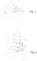
- Figure 1 illustrates an embodiment of the current rope-handling system when the guiding pole 1 is in the storage configuration.
- the guiding pole 1 is retractable and extendible.
- the embodiment comprises two guiding poles 1, and a winch comprising two drums, each being provided with an attachment rope 3 and corresponding to each guiding pole.
- the winch is located under a winch housing 4 and therefore not visible in the figure.
- Fig. 1 displays the positioning of the rope-handling system according to the present disclosure in the bow portion of a tugboat.
- the deck 21 of the tugboat is partially visible.
- the deck 21 has two elevations, the main deck being lower than the supporting surface 2 on which the guiding poles 1 are mounted. In their retracted position (i.e. in the storage configuration), the guiding poles 1 are hidden under the supporting surface 2.
- Such an arrangement may be advantageous for example in situations in which the rope-handling system is retrofitted into an existing special purpose craft.
- Such a structure with a continuous winch housing 4 and supporting surface 2 as in fig. 1 may be used also in embodiments in which there is only one guiding pole 1.
- the attachment rope 3 is shown running from an opening of the winch housing 4 to the guiding pole 1.
- the line-engaging means 13 is positioned at the end of the attachment rope 3 adjacent to the guiding pole 1.
- FIG. 2 displays the rope-handling system according to the present disclosure when one guiding pole 1 is in an extended position.
- the Y fork 12 is ready to receive a heaving line 5.
- the guiding pole 1 is in the operating configuration.
- the guiding pole 1 comprises a leg portion 16, and its base end 161 and distal end 162 are visible.
- the leg portion 16 is one rigid piece moving upwards and downwards relative to the supporting surface 2.
- the pivotable arms 11 As the guiding pole is in the operating configuration, in fig. 2 the pivotable arms 11 have been opened.
- the arms 11 are positioned so that they pivot away from each other when the guiding pole 1 is in the operating configuration.
- the attachment ends 111 of the arms are close to each other at the base of the arms 14 and connected to the distal end 162 of the leg portion through pivoting means 15.
- the free ends 112 of the arms form the boundaries between which the heaving line 5 falls to be caught by the line-engaging means 13 (not visible in fig. 2 ).
- the attachment rope 3 remains connected to the line-engaging means 13 and has been pulled outwards as the guiding pole 1 has been extended.
- Fig. 2 also displays a heaving line 5 being slung from the vessel (not shown).
- a monkey-fist 51 is visible at the end of the heaving line 5.
- the monkey-fist 51 will land on the tugboat.
- the heaving line 5 will be pulled until the monkey-fist 51 is caught in the line trap 131 of the line-engaging means 13.
- Figure 3 depicts the rope-handling system of figures 1 and 2 , where the line trap 131 of the line-engaging means 13 has caught the monkey-fist 51 (not visible) of the heaving line 5.
- the heaving line 5 pulls the line-engaging means 13 and the attachment rope 3 along with it towards the vessel.
- the tugboat is relatively close to a larger vessel being assisted (not shown), since the attachment rope 3 is pulled almost directly upwards by the heaving line 5.
- the figure shows how the opening of the winch housing 4 is formed to smoothly guide the attachment rope 3.
- the guiding pole 1 is simultaneously being retracted. This means that it is already being returned to the storage configuration.
- the base end 161 of the leg portion 16 is already below the supporting surface 2, and the distal end 162 is being lowered towards the supporting surface 2.
- the Y fork 12 is still open, but the arms 11 will close, i.e. pivot back towards each other, as the guiding pole 1 moves under the deck 21.
- FIG 4 another exemplary embodiment of the rope-handling system according to the present disclosure is depicted.
- the system of fig. 4 comprises two tiltable guiding poles 1, which are depicted schematically.
- the attachment ropes 3 have been omitted.
- the two guiding poles 1 positioned parallel to each other on a supporting surface 2 are in the storage configuration. They may be supported by the railings 6, which may have an adaptation to receive and hold the guiding pole 1.
- the tiltable guiding poles 1 may be lifted automatically, so that they can be operated from the deck of the special purpose craft, for example. They may also be lifted manually, in which case they are locked in place.
- the guiding poles 1 of in fig. 4 comprise a leg portion 16 having a base end 161 and a distal end 162. Pivoting means 15 for the arms 11 are shown. When the tiltable guiding poles 1 have been lifted, the arms 11 may be opened manually or automatically, to bring the guiding pole 1 into operating configuration.
- Figure 5 depicts a rope-handling system according to the present disclosure on land in a harbour.
- the system comprises two guiding poles 1, each comprising a pivoting means 15 and arms 11 as described above.
- the first guiding pole 1 is in the operating configuration with arms 11 open, and a heaving line 5 is being thrown into the Y fork 12.
- the second guiding pole 1 is in the storage configuration.
- the guiding poles 1 are extendible and retractable between the operating configuration and the storage configuration.
- the attachment rope 3 which in this case is a mooring line, or a winch are not shown.
- the system may function similarly to the devices presented in connection with figures 1 to 3 , and the construction of such devices is within the knowledge of the skilled person.
- the system according to figure 5 may alternatively be used so that the mooring line comes from the vessel to bee moored, and the mooring line is attached to the opposite end of the heaving line 5 than the monkey-fist 51.
- the monkey-fist 51 can be released manually from the line-engaging means 13.
- the heaving may take place manually, or through a device, such as a winch or a vehicle, as is known in the art.
- the guiding poles 1 comprise a leg portion 16, which is attached from its base end 161 to the supporting surface 2.
- the supporting surface 2 is an elevated assembly on a berth 22.
- the distal end of the guiding pole 162 and the pivoting means 15 remain above the supporting surface 2 in the retracted position, i.e. in the storage configuration.
- the supporting surface 2 comprises a guiding pole cover 23 for each guiding pole 1 extending above the supporting surface 2.
- the guiding poles 1 are retractable under the supporting surface 2.
- the guiding pole covers 23 may extend through the supporting surface 2 as one piece, or as a separate piece.
- the guiding pole covers 23 may protect the guiding poles 1 against weather conditions, rope wrap around or possible collisions by vessels.
- Figure 6 depicts an embodiment of the line-engaging means 13 in more detail.
- An attachment rope 3 is attached at one end of the line-engaging means 13.
- the line trap 131 is formed as a recess 1311 and a groove 1312 opens into the recess and directs the heaving line 5 appropriately.
- the monkey-fist 51 is shown positioned at the entrance of the recess 1311.
- the line-engaging means 13 is attached to the guiding pole 1 through contact means 132.
- the contact means 132 are notches on each side of the line-engaging means 13.
- the guiding pole 1 is equipped with a receptacle shape that can receive the contact means 132 of the line-engaging means 13.
- the contact means 132 is designed to correspond to a receptacle shape on the guiding pole 1 to releasably attach the line-engaging means 13 to the guiding pole 1.
- the line-engaging means may comprise additional directing aids, such as additional grooves or indentations to help guide the monkey-fist 51 into the line trap 131.
- a rope-handling system, a special purpose craft or a use, to which the disclosure is related, may comprise at least one of the embodiments described hereinbefore.
Landscapes
- Engineering & Computer Science (AREA)
- Mechanical Engineering (AREA)
- Ocean & Marine Engineering (AREA)
- Chemical & Material Sciences (AREA)
- Combustion & Propulsion (AREA)
- General Engineering & Computer Science (AREA)
- Environmental & Geological Engineering (AREA)
- Civil Engineering (AREA)
- Structural Engineering (AREA)
- Catching Or Destruction (AREA)
- Emergency Lowering Means (AREA)
- Load-Engaging Elements For Cranes (AREA)
Description
- The current disclosure relates to a rope handling system, to a special purpose craft and to a guiding pole.
- Special purpose crafts may be used for various tasks on sea, in harbors, as well as in inland waters. For example tugboats are used for assisting other vessels in various situations, typically requiring maneuvering in restricted waters. Tugboats can either tow the assisted vessel or push it. When towing, the tugboat and the assisted vessel are normally connected by a towline. The length of the towline may be regulated by a towing winch on the tugboat. The towline is connected to a bollard on the assisted vessel. The tasks performed by special purpose crafts may range from ice breaking to waterway maintenance, including various situations that might necessitate the attachment of a vessel to another through a rope. A similar system can also be used for mooring a vessel at a berth.
- The usual manner to connect a vessel to a special purpose craft or to a berth is to throw a heaving line from the vessel being attached on the deck of the special purpose craft or on the berth, respectively. A crew member on the special purpose craft then picks the heaving line and ties it to an end of the towline. The heaving line and the connected towline are then heaved to the vessel, released from each other, and the towline is secured to a bollard or other structures of the vessel. At berth the heaving line may already be connected to a mooring line of the vessel, and a member of the mooring crew, also called a linesman, picks the heaving line and heaves the mooring line, along with the heaving line, to berth. Then, the heaving line is released form the mooring line, and the mooring line is secured to a bollard or other structures of the berth.
- The manual arrangement has drawbacks, for example that a crew member is needed to be present on the deck of the special purpose craft. In harsh weather, the working conditions can be uncomfortable, or even hazardous. Additionally, the heaving line has a weight attached to its end to facilitate throwing, and being hit by the weight can injure a person on deck or on berth.
- Document
WO2017/167892 discloses a tugboat comprising a crane or a robot arm for handling a towing line, the crane or robot arm being provided with a grasping tool for grasping a towing line. - Document
US 2006/0102060 A1 relates to an automatic system for taking up and handling a connecting towrope between a tugboat and a towed vessel. The system comprises a fastening carriage which moves on guides around the deck of the tugboat. -
US 6 508 190 B1 discloses a remotely operable device enabling one person to attach and release a boat to and from a mooring. -
GB 1 495 040 A -
EP 3 713 826A1 discloses a tugboat comprising a hull and a line handling system comprising a line guide mechanism. - A rope-handling system according to the current disclosure is configured for catching a heaving line and characterized in that it comprises a guiding pole that is convertible between an operating configuration and a storage configuration, the guiding pole comprising pivotable arms forming a Y fork at an upper end of the guiding pole in the operating configuration of the guiding pole, a leg portion forming the upper end of the guiding pole, the arms being attached to the upper end of the pole opposite to each other wherein the arms extend in the same direction with the leg portion in the storage configuration and open away from each other when the guiding pole is converted to the operating configuration. The guiding pole further comprises line-engaging means releasably attachable at the base of the arms and connectable to an attachment rope. The line-engaging means comprises a line trap for catching a monkey-fist of the heaving line when the heaving line is directed between the arms of the Y fork from another vessel.
- The special purpose craft according to the current disclosure is characterized in that it comprises a rope-handling system according to the current disclosure.
- The use of the rope-handling system according to the present disclosure for attaching a vessel to a special purpose craft or to a land structure is also disclosed.
- The accompanying drawings, which are included to provide a further understanding of the current disclosure and constitute a part of this specification, illustrate embodiments of the disclosure and together with the description help to explain the principles of the current disclosure. In the drawings:
-
Fig. 1 displays an embodiment of the rope-handling system according to the current disclosure with the guiding pole in a storage configuration. -
Fig. 2 displays the rope-handling system according to the current disclosure in an operating configuration with an attachment rope attached to the line-engaging means. -
Fig. 3 displays the attachment rope being drawn to a vessel. -
Fig. 4 displays another embodiment of the current rope-handling system with the guiding pole in the storage configuration. -
Fig. 5 displays yet another embodiment of the current rope-handling system and a guiding pole, with the guiding pole in an operating configuration on a berth. -
Fig. 6 displays an embodiment of the line-engaging means according to the present disclosure. - Reference will now be made in detail to the embodiments of the present disclosure, examples of which are illustrated in the accompanying drawings.
- The description below discloses some embodiments in such a detail that a person skilled in the art is able to utilize the method and apparatus based on the disclosure. Not all steps of the embodiments are discussed in detail, as many of the steps will be obvious for the person skilled in the art based on this specification.
- For reasons of simplicity, item numbers will be maintained in the following exemplary embodiments in the case of repeating components.
- In one aspect, a rope-handling system is disclosed. In another aspect, a special purpose craft comprising the automatic rope-handling system according to the present disclosure is disclosed. In yet another aspect, use of the rope-handling system for attaching a vessel to a special purpose craft or to a land structure is disclosed.
- In yet another aspect, a guiding pole for catching a heaving line is disclosed. The guiding pole according to the present disclosure is characterized in that the guiding pole is convertible between an operating configuration and a storage configuration. The guiding pole comprises pivotable arms forming a Y fork in the operating configuration of the guiding pole; and a structure for releasably attaching a line-engaging means configured to catch a monkey-fist at the base of the arms.
- The rope-handling system according to the present disclosure is characterized in that it comprises a guiding pole that is convertible between an operating configuration and a storage configuration, the guiding pole comprising pivotable arms forming a Y fork in the operating configuration of the guiding pole. The arms are typically mounted at the end of the guiding pole which is designed to be the upper end in use.
- The rope-handling system further comprises line-engaging means releasably attachable at the base of the arms and connectable to an attachment rope, wherein the line-engaging means comprises a line trap for catching a monkey-fist of a heaving line when the heaving line is directed between the arms of the Y fork from a vessel.
- The rope-handling system may remove or reduce the need of a crew member on the deck of the special purpose craft when a vessel is being connected by an attachment rope. The rope-handling system is designed to catch the heaving line thrown from the vessel by the Y fork of the guiding pole. The Y fork is thus positioned so that it can catch the heaving line. A heaving line is a line or a suitable rope thrown from a vessel to another vessel or to land in order to move a rope (such as a towline or a mooring line) between the vessels or between land and a vessel. The rope is attached to the heaving line, and the heaving line is heaved to the direction in which the rope is meant to be moved. Oftentimes, and attachment rope is retrieved with the help of a heaving line. The structure and positioning of the line-engaging means may further allow connecting the attachment rope with the heaving line without further devices or manual steps.
- In embodiments where a mooring line is moved from a vessel to be moored to land for mooring, the mooring line may first be attached to the heaving line. This attachment is done suitably far away from the end with the monkey-fist, so that the monkey-fist can be flung to the Y fork on land. For example, the attachment of the mooring line can take place at the opposite end of the heaving line from the monkey-fist. When the heaving line is caught by the line trap, the heaving line may be released from the line-engaging means to be heaved to land. In such an embodiment, it is possible that the line-engaging means is not attached to an attachment rope on the land side.
- Alternatively, a winch may be used to reel in the heaving line. As the heaving line is followed by the mooring line, the mooring line would then be positioned suitably for being attached to a bollard or the like. In such embodiments, the system may comprise a winch with an attachment rope to reel in the heaving line. The winch may be suitably configured to take in the line-engaging means and a length of the heaving line.
- One of the advantages of the current system and the special purpose craft is that hazards relating to connecting a vessel to another vessel or to land structures may be reduced. The line-engaging means could hit a person catching the heaving line, exposing such persons to injury. In embodiments relating to special purpose crafts, the weather conditions may make the deck an unstable working area, adding to the hazards.
- A further advantage of the system and its use is that many types of vessels can be connected with it. No modifications are needed on the assisted vessels to improve the efficiency of attachment to a special purpose craft or to a berth.
- In the current disclosure, the term vessel, or an assisted vessel, is used to describe a seagoing vessel that is attached to a special purpose craft, such as a tugboat, or to land structures, such as a berth.
- The term attachment rope is used for a towline, or other line used to connect a special purpose craft, for example a tug, with an assisted vessel, and for a mooring line used for connecting a vessel to land structures.
- By the guiding pole being convertible between storage configuration and an operating configuration is meant that the guiding pole can be repeatedly transferred between the storage configuration and the operating configuration.
- The current rope-handling system may be used by first extending or pivoting the guiding pole to a sufficient height and opening the arms of the Y fork. At this point, the line-engaging means is positioned at the base of the arms of the guiding pole, and is attached to the attachment rope. In this position, when the heaving line is flung from a vessel towards the Y fork, the monkey-fist of the heaving line will pass through or above the Y fork and the heaving line will land on either of the arms and slide downwards to the base of the arms. When the heaving line is tightened, the monkey-fist at the end of the heaving line will move upwards and be guided to enter the line trap of the line-engaging means. The line-engaging means is releasably attached to the Y fork so that when the heaving line is pulled further, the line-engaging means becomes disconnected from the guiding pole and follows the heaving line to the vessel.
- When the heaving line is pulled back to the vessel, the line-engaging means is released from the guiding pole and, along with the attachment rope attached to it, is pulled to the vessel, where the attachment rope can be attached to the vessel.
- The rope-handling system according to the present disclosure comprises a guiding pole and line-engaging means, but additional components may be included.
- For example, a winch may be responsible for releasing the attachment rope in order for it to be heaved to the vessel. The winch may also reel in the attachment rope to a suitable length for towing or mooring. The winch may hold the attachment rope at a desired length during towing or other connection of a special purpose craft and an assisted vessel. The winch may reel the attachment rope back to the special purpose craft at the end of towing. In embodiments in which the rope-handling system is located on land structures, the winch may be movable or stationary. The attachment rope may be detachable from the winch so that a regular bollard may be used for longer-term mooring of the vessel.
- The winch may be covered by a housing which protects the winch. One winch may comprise one or two drums. If a winch comprises two drums, each of the drums may be covered by its own housing, or the two drums may share a housing. A winch housing may additionally be formed into or comprise structures that help aligning the attachment rope suitably for the other components of the current rope-handling system.
- An attachment rope may also be comprised in the system according to the present disclosure. Many designs for an attachment rope are known to the skilled person, who is able to select a suitably structured attachment rope for different applications. An attachment rope typically has a loop or another type of attaching means at its free end to facilitate the attachment of the attachment rope to the vessel being connected to the special purpose craft or to the land structures. Additionally, the deck structures of a special purpose craft may be designed to support, or to co-operate with, the rope handling system according to the present disclosure. For example the main deck may contain support structures for the guiding pole.
- In the operating configuration, the guiding pole extends above a supporting surface. The supporting surface means a solid surface surrounding the guiding pole in the operating configuration. The guiding pole may be attached to the supporting surface. Alternatively, the guiding pole may be attached to other structures, especially structures under the supporting surface. The supporting surface may be, for example a deck of a special purpose craft, a winch housing or an extension thereof. Supporting surface can also be a berth, pier or other solid surface available in a harbor or elsewhere on land.
- The guiding pole according to the present disclosure may be retractable/extendable. In one embodiment, the guiding pole is convertible between the operating configuration and the storage configuration by retracting and extending the guiding pole relative to a supporting surface. The guiding pole being retractable/extendable means that that the portion of the guiding pole which makes contact with the heaving line can be moved vertically in relation to the supporting surface between a retracted position and an extended position. Depending on the embodiment, the complete guiding pole may move, for example if the guiding pole is made of one rigid piece. For example, a leg portion of the guiding pole may be rigid. Alternatively, the portions of the guiding ole making contact with the heaving line (i.e. the upper part) may move vertically, while some parts of the guiding pole remain stationary. For example, the guiding pole may be telescopic. In the extended position, the upper end of the guiding pole is higher than in the retracted position. In the retracted position, the guiding pole may be entirely under the supporting surface. However, in some embodiments, the guiding pole may be designed to remain partially above the supporting surface also in the retracted position. In one embodiment of the system, the guiding pole is retractable completely under the supporting surface.
- The supporting surface may be a deck of a special purpose craft, or a surface of a land structure. By a deck of the special purpose craft is herein meant the outer surface of the special purpose craft above which other structures such as the deckhouse are positioned. Depending on the specifics of the special purpose craft, the deck may comprise surface on a single height. Alternatively, the deck may comprise surfaces on more than one height. The overall plane of a deck is typically substantially horizontal, but deviations commonly occur for practical reasons, such as for improving water run-off from the deck. When the guiding pole according to the present disclosure is retracted under the deck, it means that the guiding pole is retracted under any part of the deck. Alternatively, the guiding pole may be retracted under the main deck, the main deck meaning the overall level of the deck.
- In embodiments relating to land structures, the supporting surface may be the surface present in harbor, such as a berth, pier, or the like. It may contain additional structures, for example metal plating, for attaching the guiding pole onto the supporting surface. The current system can be used additionally outside of harbors. For example in channels, especially at locks, the current rope-handling system may be utilized. The system can also be used at various smaller-scale landing places where personnel is not necessarily always present.
- In one embodiment of the system, the guiding pole is convertible between the operating configuration and the storage configuration by tilting the guiding pole. Tilting guiding pole may be advantageous in situations where the space under the supporting surface, especially under the deck of a special purpose craft, is limited. Such situations may arise, for example when the system according to the present disclosure is retrofitted into an existing special purpose craft. Designing the railings to contain support structures for the guiding pole may have advantages in tilting embodiments, for example if it is not possible to attach the guiding pole sufficiently rigidly to the support surface or under it.
- Tilting may be effected at the base of the leg portion or above the base. The leg portion may comprise more than one tilting position.
- According to the invention, the guiding pole comprises a leg portion with a base end and a distal end, and the pivotable arms are attached to the distal end opposite to each other, and wherein the arms extend in the same direction with the leg portion in the storage configuration, and open away from each other when the guiding pole is converted to the operating configuration.
- In embodiments where the guiding pole is on a special purpose craft, it is typically possible to operate the guiding pole from the bridge of the special purpose craft so that a crew member is not needed on the deck to set up the rope-handling system according to the present disclosure for receiving the heaving line. On land, such as in a harbor, the configuration of the guiding pole can be converted from separate controls. The controls may be stationary or portable. On land, the guiding pole may be converted manually, as the working environment is more sheltered and stable than on a special purpose craft. In one embodiment of the system, the configuration of the guiding pole is convertible remotely. By a remotely convertible configuration of the guiding pole is in the current disclosure meant a guiding pole that can be operated from outside the special purpose craft, or through an at least partly wireless system. Such an embodiment may be implemented as a part of a remotely controllable special purpose craft, or as a part of an autonomous special purpose craft. In one embodiment, the special purpose craft according to the present disclosure is remotely-controllable or autonomous.
- The guiding pole according to the present disclosure may comprise a rigid leg portion. The guiding pole may comprise metal, such as aluminum or steel. It can also be made at least partly of composite material, such as plastic, plastic composite, carbon fiber etc. It is possible to construct the leg portion and the arms of different materials, each of which may be independently selected from materials having suitable properties. For example, the leg portion may be made of metal, such as steel, and the arms may comprise carbon fiber.
- The leg portion may be attached to machinery which allows the guiding pole to be moved upwards and downwards relative to the supporting surface. The leg portion may comprise structures that take part in converting the configuration of the guiding pole. For example a rack-and-pinion type of engagement between the guiding pole and the lifting machinery can be envisaged in extendable and retractable embodiments. In embodiments where the guiding pole is tiltable, a hinge with a locking mechanism may be present.
- The conversion between an operating configuration and a storage configuration may be implemented with an electric motor, hydraulic system. Also other types of systems are known in the art. An engine on the special purpose craft or a separate motor, such as an electric motor, can be used for powering the conversion of the guiding pole's configuration.
- The lifting machinery may allow turning the guiding pole around its longitudinal axis. The lifting machinery itself may be used to turn the guiding pole. Alternatively, the guiding pole may be turnable independently of the lifting machinery. Such embodiments may be advantageous in facilitating the aiming of the heaving line from the a vessel. A turnable guiding pole may be used to position the Y fork suitably relative to the vessel. This may be especially advantageous in stationary embodiments. The possibility to turn the guiding pole may have advantages also in embodiments on a special purpose craft. Especially in rough weather, being able to turn the guiding pole in addition to or instead of adjusting the position of the special purpose craft may be useful.
- The leg portion comprises a base end, which is the lower end of the guiding pole when the guiding pole is mounted on the supporting surface. The leg portion also comprises a distal end, which is the upper end of the guiding pole when the pole is mounted on the supporting surface. When the guiding pole is converted to the operating configuration, the base end may be lifted on the level of the supporting surface or even above it. However, it is possible that the base end remains below the supporting surface even in the operating configuration of guiding pole. The level which the base end reaches depends on the specific embodiment in question, for example on the machinery that is used for converting the guiding pole between operating configuration and storage configuration.
- The guiding pole comprises pivotable arms. When the arms pivot away from each other, they form an Y fork. This is referred to as opening of the arms. The arms may comprise two ends, an attachment end and a free end. The arms are in contact with the leg portion through the attachment end. The arms may be connected to the leg portion through pivoting means. The pivoting means may be a hinge that is designed to allow the pivoting of the arms away from each other to a predetermined extend, so that the desired angle of the Y fork is achieved. The pivoting means may be a separate or an integral piece of the guiding pole. The pivoting means are located at or near the base of the arms, which is the position where the line trap is located.
- The pivoting means may function passively, i.e. so that the weight of the arms causes the opening of the arms. The pivoting means may comprise resistance means that contribute to smooth and controlled opening of the arms, avoiding unwantedly fast opening of the arms. The pivoting means may alternatively function actively, i.e. so that the arms open and close only when desired. Actively functioning arms open and close independently of the extending and retracting of the guiding pole. Thus in the actively functioning embodiments of the pivoting means the arms may remain closed even when the guiding pole is extended, and open only when the pivoting means are activated. In other words, the operation configuration can be finalized independently of lifting the leg portion.
- The free end of each arm may comprise additional components. For example lights can be mounted on the free ends of the arms to improve the visibility of the Y fork under foggy or dark conditions.
- When the arms extend in the same direction as the guiding pole, they form an extension of the leg portion. In other words, they are folded against each other side by side.
- The arms form an Y fork in the operating configuration. The angle of the fork may vary, and may be in the range of 50 to 120 degrees. For example, an angle of 60 to 100 degrees, such as 60, 70, 80 or 90 degrees may be used.
- The length of the leg portion, as well as the arms depends on the size and typical use of the system according to the present disclosure. Practical aspects determine the suitable lengths and the ratio between the length of the leg portion and the length of the arms. In some embodiments, the arms may be of different length. For example, the guiding pole may measure 2 - 4 m in height, for example 3 or 3.5 m, in the operating configuration. It is alternatively possible, that the leg portion of the guiding pole measures 2 - 4 m, such as 3 m, in height in the operating configuration. The ease of use of the system may benefit from a higher guiding pole, but the space available under or on the supporting surface may limit the dimensions of the guiding pole.
- In one embodiment of the system, the guiding pole is mounted on the deck of a special purpose craft. The system according to the present disclosure may increase the versatility of such special purpose crafts. The system can also be retrofitted to existing crafts, increasing their usability.
- In one embodiment of the system, the guiding pole is positioned on the bow side of a towing winch. In case there are more than one winch, an alternative is that the guiding pole is positioned on the bow side of at least one of them. It may also be possible to position the guiding pole on the bow side of all of the winches.
- By a special purpose craft is in this disclosure meant any vessel that may assist other vessels by towing. The primary task of the special purpose craft does not necessarily need to be the assistance of other vessels. There are a number of types of special purpose crafts for various tasks. In one embodiment, the special purpose craft is a harbor tug, an escort tug, an ocean-going tug, an ice breaker, a supply vessel, an anchor handler or a workboat. The special purpose craft according to the present disclosure may have the advantage that while it is capable of automating the connection between the heaving line and the attachment rope, the crowding of the deck is not increased. Therefore, the special purpose craft may be usable for more variable tasks, possibly also involving people, machinery or goods being present on the deck. This is due to the guiding pole being concealed under the deck, or stowed at the side of the deck in the storage configuration. Also, a lowered guiding pole does not hamper the visibility from the bridge of the special purpose craft.
- In one embodiment of the system, the guiding pole is mounted on a land structure, such as on a berth. This may improve the efficiency of mooring vessels. Especially at a harbor the number of personnel present may be reduced. Additionally, by suitably positioning more than one of the systems according to the present disclosure, it may be possible to simultaneously attach the vessel at a corresponding number of positions.
- It may be possible to conceal the complete rope-handling system according to the present disclosure under the supporting surface. Such embodiments would not increase the obstacles for work conducted at the harbor, such as loading and unloading the vessel while providing the benefits of automation.
- The rope-handling system according to the present disclosure further comprises line-engaging means. The line-engaging means is able to make contact with both the attachment rope and the heaving line. In other words, it comprises the structures which catch the heaving line, as well as connections to the attachment rope. The line-engaging means further comprise the elements for positioning it suitably for receiving the heaving line in order to catch it. The line-engaging means is releasably attachable to the guiding pole. Since, once landed on the Y fork of the guiding pole, the heaving line slides down on the lowest position between the pivotable arms, i.e. at the base of the arms, this is also a suitable position for the line-engaging means.
- By a heaving line is meant a line that is used to retrieve the attachment rope from the special purpose craft or from the berth by flinging it from a vessel. The heaving line may comprise weight at the end which is travels to the special purpose craft or to the berth to increase the flight distance and to improve aiming accuracy of the heaving line. Such a throwing weight may be called a monkey-fist. The weight can be a ball-like knot of the same name, or any suitably sized and weighted object, such as a sandbag, attached to the end of the heaving line. The diameter of a monkey-fist may be 5-15 cm, for example 1-10 cm.
- The line-engaging means comprises a line trap, which is the structure catching the monkey-fist. When a heaving line resting on the Y fork is pulled towards the vessel, or conversely, if the distance between the special purpose craft or the berth and the vessel increases, the monkey-fist will move upwards substantially along the leg portion of the guiding pole towards the base of the Y fork (and thus towards the line-engaging means) and will eventually be caught by the line trap of the line-engaging means.
- The rope-handling system according to the present disclosure may be usable in a broad range of height difference between special purpose crafts or berths and vessels. In situations where the heaving line is received by the Y fork from a similar height, the heaving line will run substantially horizontally between the Y fork and the vessel, and the heaving line naturally lies at the base of the Y fork. In case the vessel is a large container ship, for example, the heaving line is thrown from a position that is much higher than the Y fork. In such a situation, the direction of the heaving line when it is being pulled towards the vessel may significantly deviate from horizontal, and even approach vertical. However, in such a situation, adjusting the distance between the Y fork and the vessel may be used to adjust the running direction of the heaving line. Alternatively, the height of the leg portion or the angle between the arms of the guiding pole may be adjusted. Also the shape of the line trap can be adjusted so that the angle of the heaving line can be taken into account.
- The line trap may be structured in many ways. For example, it may comprise a partially closed channel having an opening extending along the length of the channel, the opening being wider in the direction from which the monkey-fist approaches the line trap, so that the monkey-fist will enter the channel. At the end of the channel, the opening is small enough that the monkey-fist cannot exit the channel, but the heaving line still fits through the opening. The channel may be funnel-shaped, tapering towards its end.
- In one embodiment of the system, the line trap for catching the monkey-fist of the heaving line comprises a recess for receiving the monkey-fist and a groove opening into the recess for guiding the heaving line.
- It is further possible to secure the heaving line in place in the line trap by locking means. In one embodiment of the system, the line trap comprises locking means for releasably securing the monkey-fist to the line trap. This avoids the unintended release of the monkey-fist while the attachment rope is heaved to the vessel, in case the heaving line or the attachment rope slackens and the orientation of the line-engaging means relative to the attachment rope and/or the heaving line changes. Various unidirectional gates and clips are known in the art to this effect.
- The line-engaging means is releasably attachable to the base of the Y fork. When the rope-handling system according to the present disclosure is ready to receive a heaving line, the line-engaging means is attached to the guiding pole with the line trap positioned to capture the monkey-fist of the heaving line. When the heaving line is pulled, after it has been caught by the line trap, the line-engaging means is released from the guiding pole, and it continues to be pulled towards the assisted vessel. Since also the attachment rope is attached to the line-engaging means, it will also follow towards the assisted vessel.
- The release of the line-engaging means from the guiding pole may be passive, i.e. it does not require any structural changes in the line-engaging means nor in the guiding pole structures to which the line-engaging means has been attached. In an embodiment, the line-engaging means is attached to a hook that opens to the direction in which the heaving line is being pulled. Alternatively, the line-engaging means and/or the guiding pole may comprise a structure that resists the release of the line-engaging means from the guiding pole. In such a case, reversible shape change, for example, may be needed to release the line-engaging means from the guiding pole. This can be brought about by various bendable lip or notch solutions. Also electric release mechanisms are possible.
- In one embodiment, the special purpose craft according to the current disclosure comprises two or more rope-handling systems. In many situations, the special purpose craft according to the present disclosure comprises one rope-handling system. Two or more rope-handling systems are, however, possible. The advantage of having more than one rope-handling systems on one special purpose craft is that more than one heaving line may be received at the same time, allowing the attachment of more than one attachment rope simultaneously. Even if only one attachment rope is attached at a given time, differently positioned guiding poles may allow the special purpose craft to approach the other vessel from various directions, providing more flexibility to the special purpose craft and making it more efficient.
-
Figure 1 illustrates an embodiment of the current rope-handling system when theguiding pole 1 is in the storage configuration. In the embodiment offig.1 , theguiding pole 1 is retractable and extendible. The embodiment comprises two guidingpoles 1, and a winch comprising two drums, each being provided with an attachment rope 3 and corresponding to each guiding pole. The winch is located under a winch housing 4 and therefore not visible in the figure. -
Fig. 1 displays the positioning of the rope-handling system according to the present disclosure in the bow portion of a tugboat. Thedeck 21 of the tugboat is partially visible. Thedeck 21 has two elevations, the main deck being lower than the supportingsurface 2 on which the guidingpoles 1 are mounted. In their retracted position (i.e. in the storage configuration), the guidingpoles 1 are hidden under the supportingsurface 2. Such an arrangement may be advantageous for example in situations in which the rope-handling system is retrofitted into an existing special purpose craft. Such a structure with a continuous winch housing 4 and supportingsurface 2 as infig. 1 may be used also in embodiments in which there is only oneguiding pole 1. - The attachment rope 3 is shown running from an opening of the winch housing 4 to the
guiding pole 1. The line-engagingmeans 13 is positioned at the end of the attachment rope 3 adjacent to theguiding pole 1. -
Figure 2 displays the rope-handling system according to the present disclosure when oneguiding pole 1 is in an extended position. TheY fork 12 is ready to receive a heaving line 5. In other words, theguiding pole 1 is in the operating configuration. Theguiding pole 1 comprises aleg portion 16, and itsbase end 161 anddistal end 162 are visible. Theleg portion 16 is one rigid piece moving upwards and downwards relative to the supportingsurface 2. - As the guiding pole is in the operating configuration, in
fig. 2 thepivotable arms 11 have been opened. Thearms 11 are positioned so that they pivot away from each other when theguiding pole 1 is in the operating configuration. The attachment ends 111 of the arms are close to each other at the base of the arms 14 and connected to thedistal end 162 of the leg portion through pivoting means 15. The free ends 112 of the arms form the boundaries between which the heaving line 5 falls to be caught by the line-engaging means 13 (not visible infig. 2 ). - The attachment rope 3 remains connected to the line-engaging
means 13 and has been pulled outwards as theguiding pole 1 has been extended. -
Fig. 2 also displays a heaving line 5 being slung from the vessel (not shown). A monkey-fist 51 is visible at the end of the heaving line 5. The monkey-fist 51 will land on the tugboat. The heaving line 5 will be pulled until the monkey-fist 51 is caught in theline trap 131 of the line-engagingmeans 13. -
Figure 3 depicts the rope-handling system offigures 1 and 2 , where theline trap 131 of the line-engagingmeans 13 has caught the monkey-fist 51 (not visible) of the heaving line 5. The heaving line 5 pulls the line-engagingmeans 13 and the attachment rope 3 along with it towards the vessel. In this situation, the tugboat is relatively close to a larger vessel being assisted (not shown), since the attachment rope 3 is pulled almost directly upwards by the heaving line 5. The figure shows how the opening of the winch housing 4 is formed to smoothly guide the attachment rope 3. - The
guiding pole 1 is simultaneously being retracted. This means that it is already being returned to the storage configuration. Thebase end 161 of theleg portion 16 is already below the supportingsurface 2, and thedistal end 162 is being lowered towards the supportingsurface 2. TheY fork 12 is still open, but thearms 11 will close, i.e. pivot back towards each other, as theguiding pole 1 moves under thedeck 21. - In
figure 4 , another exemplary embodiment of the rope-handling system according to the present disclosure is depicted. The system offig. 4 comprises twotiltable guiding poles 1, which are depicted schematically. The attachment ropes 3 have been omitted. Infig. 4 , the two guidingpoles 1 positioned parallel to each other on a supportingsurface 2 are in the storage configuration. They may be supported by the railings 6, which may have an adaptation to receive and hold theguiding pole 1. Thetiltable guiding poles 1 may be lifted automatically, so that they can be operated from the deck of the special purpose craft, for example. They may also be lifted manually, in which case they are locked in place. - The guiding
poles 1 of infig. 4 comprise aleg portion 16 having abase end 161 and adistal end 162. Pivoting means 15 for thearms 11 are shown. When thetiltable guiding poles 1 have been lifted, thearms 11 may be opened manually or automatically, to bring theguiding pole 1 into operating configuration. -
Figure 5 depicts a rope-handling system according to the present disclosure on land in a harbour. The system comprises two guidingpoles 1, each comprising a pivoting means 15 andarms 11 as described above. Thefirst guiding pole 1 is in the operating configuration witharms 11 open, and a heaving line 5 is being thrown into theY fork 12. Thesecond guiding pole 1 is in the storage configuration. The guidingpoles 1 are extendible and retractable between the operating configuration and the storage configuration. - The attachment rope 3, which in this case is a mooring line, or a winch are not shown. However, the system may function similarly to the devices presented in connection with
figures 1 to 3 , and the construction of such devices is within the knowledge of the skilled person. - The system according to
figure 5 may alternatively be used so that the mooring line comes from the vessel to bee moored, and the mooring line is attached to the opposite end of the heaving line 5 than the monkey-fist 51. The monkey-fist 51 can be released manually from the line-engagingmeans 13. The heaving may take place manually, or through a device, such as a winch or a vehicle, as is known in the art. - The guiding
poles 1 comprise aleg portion 16, which is attached from itsbase end 161 to the supportingsurface 2. The supportingsurface 2 is an elevated assembly on aberth 22. In this embodiment, the distal end of theguiding pole 162 and the pivoting means 15 remain above the supportingsurface 2 in the retracted position, i.e. in the storage configuration. - In the embodiment of
fig. 5 , the supportingsurface 2 comprises aguiding pole cover 23 for eachguiding pole 1 extending above the supportingsurface 2. The guidingpoles 1 are retractable under the supportingsurface 2. The guiding pole covers 23 may extend through the supportingsurface 2 as one piece, or as a separate piece. The guiding pole covers 23 may protect the guidingpoles 1 against weather conditions, rope wrap around or possible collisions by vessels. -
Figure 6 depicts an embodiment of the line-engagingmeans 13 in more detail. An attachment rope 3 is attached at one end of the line-engagingmeans 13. Theline trap 131 is formed as arecess 1311 and agroove 1312 opens into the recess and directs the heaving line 5 appropriately. - In
fig. 6 , the monkey-fist 51 is shown positioned at the entrance of therecess 1311. The line-engagingmeans 13 is attached to theguiding pole 1 through contact means 132. In the embodiment offig. 6 , the contact means 132 are notches on each side of the line-engagingmeans 13. Theguiding pole 1 is equipped with a receptacle shape that can receive the contact means 132 of the line-engagingmeans 13. In other words, the contact means 132 is designed to correspond to a receptacle shape on theguiding pole 1 to releasably attach the line-engagingmeans 13 to theguiding pole 1. - In addition to the features visible in
fig. 6 , the line-engaging means may comprise additional directing aids, such as additional grooves or indentations to help guide the monkey-fist 51 into theline trap 131. - It is obvious to a person skilled in the art that with the advancement of technology, the basic idea of the rope-handling system, the special purpose craft and the use may be implemented in various ways. The embodiments are thus not limited to the examples described above; instead they may vary within the scope of the claims.
- The embodiments described hereinbefore may be used in any combination with each other. Several of the embodiments may be combined together to form a further embodiment. A rope-handling system, a special purpose craft or a use, to which the disclosure is related, may comprise at least one of the embodiments described hereinbefore.
Claims (15)
- A rope-handling system configured for catching a heaving line (5) characterized in that it comprises- a guiding pole (1) that is convertible between an operating configuration and a storage configuration, the guiding pole comprising• pivotable arms (11) forming a Y fork (12) at an upper end of the guiding pole (1) in the operating configuration of the guiding pole,• a leg portion (16) with a base end (161) and a distal end (162), and the pivotable arms (11) are attached to the distal end opposite to each other, and wherein the arms extend in the same direction with the leg portion in the storage configuration, and open away from each other when the guiding pole is converted to the operating configuration;- line-engaging means (13) releasably attachable at the base of the arms (14) and connectable to an attachment rope (3); wherein- the line-engaging (13) means comprises a line trap (131) for catching a monkey-fist (51) of the heaving line (5) when the heaving line is directed between the arms (11) of the Y fork (12) from a vessel.
- The system according to claim 1, wherein the guiding pole (1) is convertible between the operating configuration and the storage configuration by retracting and extending the guiding pole (1) relative to a supporting surface (2).
- The system according to claim 2, wherein the guiding pole (1) is retractable completely under the supporting surface (2).
- The system according to claim 1, wherein the guiding pole (1) is convertible between the operating configuration and the storage configuration by tilting the guiding pole.
- The system according to any of the preceding claims, wherein the configuration of the guiding pole (1) convertible remotely.
- The system according to any of the preceding claims, wherein the line trap (131) for catching the monkey-fist (51) of the heaving line (5) comprises a recess (1311) for receiving the monkey-fist and a groove (1312) opening into the recess for guiding the heaving line.
- The system according to any of the preceding claims, wherein the line trap (131) comprises locking means for releasably securing the monkey-fist (51) to the line trap.
- The system according to any of the preceding claims, wherein the guiding pole (1) is mounted on a land structure, such as on a berth (21).
- The system according to any of the claims 1-8, wherein the guiding pole (1) is mounted on the deck of a special purpose craft (22).
- The system according to claim 9, wherein the guiding pole (1) is positioned on the bow side of a towing winch (4).
- A special purpose craft (6) comprising the rope-handling system according to claim 9 or 10.
- The special purpose craft (6) according to claim 11 comprising two or more rope-handling systems.
- The special purpose craft (6) according to claim 11 or 12, wherein the special purpose craft is a tugboat, such as a harbor tug, an escort tug, an ocean-going tug, or an ice breaker, a supply vessel, an anchor handler or a workboat.
- The special purpose craft (6) according to any of claims 11-13, wherein the special purpose craft is remotely-controllable or autonomous.
- Use of the rope-handling system according to any of claims 1-10 for attaching a vessel to a special purpose craft or to a land structure.
Applications Claiming Priority (2)
| Application Number | Priority Date | Filing Date | Title |
|---|---|---|---|
| FI20185301A FI128398B (en) | 2018-03-29 | 2018-03-29 | Rope-handling system, special purpose craft, use of the rope-handling system and guiding pole |
| PCT/FI2019/050222 WO2019185984A1 (en) | 2018-03-29 | 2019-03-15 | Rope-handling system, special purpose craft, use of the rope-handling system and guiding pole |
Publications (4)
| Publication Number | Publication Date |
|---|---|
| EP3774515A1 EP3774515A1 (en) | 2021-02-17 |
| EP3774515A4 EP3774515A4 (en) | 2021-12-29 |
| EP3774515B1 true EP3774515B1 (en) | 2025-02-19 |
| EP3774515C0 EP3774515C0 (en) | 2025-02-19 |
Family
ID=68060960
Family Applications (1)
| Application Number | Title | Priority Date | Filing Date |
|---|---|---|---|
| EP19778259.2A Active EP3774515B1 (en) | 2018-03-29 | 2019-03-15 | Rope-handling system, special purpose craft, use of the rope-handling system and guiding pole |
Country Status (5)
| Country | Link |
|---|---|
| EP (1) | EP3774515B1 (en) |
| CN (1) | CN112805215B (en) |
| AU (1) | AU2019244313B2 (en) |
| FI (1) | FI128398B (en) |
| WO (1) | WO2019185984A1 (en) |
Families Citing this family (6)
| Publication number | Priority date | Publication date | Assignee | Title |
|---|---|---|---|---|
| GB2568534B (en) | 2017-11-20 | 2020-12-02 | Svitzer As | Tugboat with a moveable line guide mechanism |
| GB2568535B (en) | 2017-11-20 | 2020-12-02 | Svitzer As | Line handling system for coupling together lines on a tugboat |
| GB2568533B (en) | 2017-11-20 | 2020-12-02 | Svitzer As | Tugboat having a line handling system |
| WO2021175624A1 (en) * | 2020-03-06 | 2021-09-10 | Svitzer A/S | Mooring device, mooring system and vessel |
| DK202001321A1 (en) * | 2020-11-23 | 2022-05-24 | Svitzer As | Line handling system |
| DE102021111952A1 (en) | 2021-05-07 | 2022-11-10 | Macgregor Germany Gmbh & Co. Kg | system and procedures |
Family Cites Families (17)
| Publication number | Priority date | Publication date | Assignee | Title |
|---|---|---|---|---|
| US3757722A (en) * | 1972-04-21 | 1973-09-11 | Us Navy | Submersible submersible underway docking unit |
| US3922992A (en) * | 1974-05-29 | 1975-12-02 | Texaco Inc | Single point vessel mooring system |
| GB1495040A (en) * | 1975-10-25 | 1977-12-14 | Texaco Development Corp | Single point vessel mooring system |
| CN85104776B (en) * | 1985-06-20 | 1987-07-15 | 日本钢管株式会社 | mooring device |
| US4706594A (en) * | 1986-05-02 | 1987-11-17 | Joel Burns | Boat mooring line guide and holder |
| NL1001302C2 (en) * | 1995-09-27 | 1997-03-28 | Willem Pot | Emergency towing device for vessels. |
| NL1009938C1 (en) * | 1998-08-25 | 2000-02-29 | Imc Group B V | Emergency towing device for vessels. |
| ES1042352Y (en) * | 1999-03-18 | 2000-01-01 | Lopez Jose Parra | MOORING POINT FOR BOATS. |
| US6508190B1 (en) | 2000-09-27 | 2003-01-21 | Daniel Norton | Safe remotely operated single operator personal boat mooring system |
| ES2245528B1 (en) | 2002-07-26 | 2007-03-16 | Sar Remolcadores, S.L | AUTOMATIC SYSTEM OF COLLECTION AND HANDLING OF SIRGA FOR HITCH BETWEEN TOWING AND TOWING VESSEL. |
| US6925951B1 (en) * | 2004-02-09 | 2005-08-09 | Delong Mark | Boat docking rope cuffs |
| WO2010112603A1 (en) * | 2009-04-02 | 2010-10-07 | Single Buoy Moorings Inc. | Disconnectable chain connector |
| US20130167434A1 (en) * | 2011-12-30 | 2013-07-04 | Gregory Scott Firth | Pole Saw Guide |
| MX353541B (en) * | 2012-07-25 | 2018-01-18 | Single Buoy Moorings | In-line mooring connector and tensioner. |
| RU2712137C2 (en) * | 2015-05-12 | 2020-01-24 | Сингл Бой Мурингс Инк. | Mooring line connector assembly for connecting mooring line to floating structure |
| DK179634B1 (en) | 2016-03-31 | 2019-03-05 | A.P. Møller - Mærsk A/S | A tugboat with a crane for handling a towing line |
| GB2568534B (en) * | 2017-11-20 | 2020-12-02 | Svitzer As | Tugboat with a moveable line guide mechanism |
-
2018
- 2018-03-29 FI FI20185301A patent/FI128398B/en active IP Right Grant
-
2019
- 2019-03-15 WO PCT/FI2019/050222 patent/WO2019185984A1/en not_active Ceased
- 2019-03-15 CN CN201980035707.7A patent/CN112805215B/en active Active
- 2019-03-15 AU AU2019244313A patent/AU2019244313B2/en active Active
- 2019-03-15 EP EP19778259.2A patent/EP3774515B1/en active Active
Also Published As
| Publication number | Publication date |
|---|---|
| CN112805215B (en) | 2024-03-22 |
| AU2019244313B2 (en) | 2024-09-26 |
| WO2019185984A1 (en) | 2019-10-03 |
| EP3774515C0 (en) | 2025-02-19 |
| FI20185301A1 (en) | 2019-09-30 |
| FI128398B (en) | 2020-04-30 |
| CN112805215A (en) | 2021-05-14 |
| EP3774515A4 (en) | 2021-12-29 |
| EP3774515A1 (en) | 2021-02-17 |
| AU2019244313A1 (en) | 2020-11-26 |
Similar Documents
| Publication | Publication Date | Title |
|---|---|---|
| FI128398B (en) | Rope-handling system, special purpose craft, use of the rope-handling system and guiding pole | |
| EP3365224B1 (en) | System and method for launch and recovery of a marine vessel | |
| US5378851A (en) | System for handling a remotely operated vessel | |
| WO2016116771A1 (en) | Multifunctional aft door | |
| DK180450B1 (en) | A method and device for handling a mooring line | |
| NL8105697A (en) | STOPPING DEVICE FOR HOLDING A BUOY LINE THAT CONNECTS A MORE ANCHOR WITH THE ASSOCIATED BUOY. | |
| WO2009070034A2 (en) | Method for picking up and towing a structure under water | |
| EP1535831B1 (en) | Automatic system for taking up and handling a connecting towrope between a tugboat and a towed vessel | |
| US6736082B2 (en) | Method and system for connecting an underwater buoy to a vessel | |
| US6508190B1 (en) | Safe remotely operated single operator personal boat mooring system | |
| EP0767750B1 (en) | A method of manipulating a connecting element in shipping | |
| EP2623413B1 (en) | A method and system of providing access between a floating vessel and a marine structure | |
| US7882792B2 (en) | Auxiliary floating structure and procedure for descent of equipment into the sea | |
| US4246860A (en) | Method for anchor retrieval | |
| EP1268267B1 (en) | A floating arrangement and methods related thereto | |
| CN117208169A (en) | A return capsule maritime salvage and recovery system and its working method | |
| US4392447A (en) | Offshore mooring system | |
| KR102659975B1 (en) | Vessels and methods equipped with semi-automatic or automatic mooring systems | |
| RU2084372C1 (en) | System of sea facilities interacting in open sea | |
| CN114475914A (en) | Ship | |
| GB2562708A (en) | A framework for suspending a load from a boat | |
| JPS5937438Y2 (en) | Oil fence expansion ship | |
| CN118907304B (en) | Anchor lifting and dropping method for semi-submerged shallow water area | |
| Nikas | Where the Street Meets the Sea: A Nautical Glossary for Maritime Lawyers | |
| CN121929270A (en) | An automatic unhooking system for unmanned surface vessels at sea and its operation method |
Legal Events
| Date | Code | Title | Description |
|---|---|---|---|
| STAA | Information on the status of an ep patent application or granted ep patent |
Free format text: STATUS: THE INTERNATIONAL PUBLICATION HAS BEEN MADE |
|
| PUAI | Public reference made under article 153(3) epc to a published international application that has entered the european phase |
Free format text: ORIGINAL CODE: 0009012 |
|
| STAA | Information on the status of an ep patent application or granted ep patent |
Free format text: STATUS: REQUEST FOR EXAMINATION WAS MADE |
|
| 17P | Request for examination filed |
Effective date: 20201029 |
|
| AK | Designated contracting states |
Kind code of ref document: A1 Designated state(s): AL AT BE BG CH CY CZ DE DK EE ES FI FR GB GR HR HU IE IS IT LI LT LU LV MC MK MT NL NO PL PT RO RS SE SI SK SM TR |
|
| AX | Request for extension of the european patent |
Extension state: BA ME |
|
| DAV | Request for validation of the european patent (deleted) | ||
| DAX | Request for extension of the european patent (deleted) | ||
| A4 | Supplementary search report drawn up and despatched |
Effective date: 20211201 |
|
| RIC1 | Information provided on ipc code assigned before grant |
Ipc: B63B 21/00 20060101ALN20211125BHEP Ipc: B66D 3/00 20060101ALI20211125BHEP Ipc: E02B 3/24 20060101ALI20211125BHEP Ipc: B63B 35/68 20060101ALI20211125BHEP Ipc: B63B 21/58 20060101ALI20211125BHEP Ipc: B63B 21/04 20060101AFI20211125BHEP |
|
| STAA | Information on the status of an ep patent application or granted ep patent |
Free format text: STATUS: EXAMINATION IS IN PROGRESS |
|
| 17Q | First examination report despatched |
Effective date: 20231103 |
|
| RIC1 | Information provided on ipc code assigned before grant |
Ipc: B63B 21/00 20060101ALN20240708BHEP Ipc: B63B 21/54 20060101ALI20240708BHEP Ipc: B66D 3/00 20060101ALI20240708BHEP Ipc: E02B 3/24 20060101ALI20240708BHEP Ipc: B63B 35/68 20060101ALI20240708BHEP Ipc: B63B 21/58 20060101ALI20240708BHEP Ipc: B63B 21/04 20060101AFI20240708BHEP |
|
| RIC1 | Information provided on ipc code assigned before grant |
Ipc: B63B 21/00 20060101ALN20240806BHEP Ipc: B63B 21/54 20060101ALI20240806BHEP Ipc: B66D 3/00 20060101ALI20240806BHEP Ipc: E02B 3/24 20060101ALI20240806BHEP Ipc: B63B 35/68 20060101ALI20240806BHEP Ipc: B63B 21/58 20060101ALI20240806BHEP Ipc: B63B 21/04 20060101AFI20240806BHEP |
|
| GRAP | Despatch of communication of intention to grant a patent |
Free format text: ORIGINAL CODE: EPIDOSNIGR1 |
|
| STAA | Information on the status of an ep patent application or granted ep patent |
Free format text: STATUS: GRANT OF PATENT IS INTENDED |
|
| RIC1 | Information provided on ipc code assigned before grant |
Ipc: B63B 21/00 20060101ALN20240902BHEP Ipc: B63B 21/54 20060101ALI20240902BHEP Ipc: B66D 3/00 20060101ALI20240902BHEP Ipc: E02B 3/24 20060101ALI20240902BHEP Ipc: B63B 35/68 20060101ALI20240902BHEP Ipc: B63B 21/58 20060101ALI20240902BHEP Ipc: B63B 21/04 20060101AFI20240902BHEP |
|
| INTG | Intention to grant announced |
Effective date: 20240919 |
|
| GRAS | Grant fee paid |
Free format text: ORIGINAL CODE: EPIDOSNIGR3 |
|
| GRAA | (expected) grant |
Free format text: ORIGINAL CODE: 0009210 |
|
| STAA | Information on the status of an ep patent application or granted ep patent |
Free format text: STATUS: THE PATENT HAS BEEN GRANTED |
|
| AK | Designated contracting states |
Kind code of ref document: B1 Designated state(s): AL AT BE BG CH CY CZ DE DK EE ES FI FR GB GR HR HU IE IS IT LI LT LU LV MC MK MT NL NO PL PT RO RS SE SI SK SM TR |
|
| REG | Reference to a national code |
Ref country code: GB Ref legal event code: FG4D |
|
| REG | Reference to a national code |
Ref country code: CH Ref legal event code: EP |
|
| REG | Reference to a national code |
Ref country code: DE Ref legal event code: R096 Ref document number: 602019066197 Country of ref document: DE |
|
| REG | Reference to a national code |
Ref country code: IE Ref legal event code: FG4D |
|
| U01 | Request for unitary effect filed |
Effective date: 20250306 |
|
| U07 | Unitary effect registered |
Designated state(s): AT BE BG DE DK EE FI FR IT LT LU LV MT NL PT RO SE SI Effective date: 20250313 |
|
| U20 | Renewal fee for the european patent with unitary effect paid |
Year of fee payment: 7 Effective date: 20250327 |
|
| PG25 | Lapsed in a contracting state [announced via postgrant information from national office to epo] |
Ref country code: RS Free format text: LAPSE BECAUSE OF FAILURE TO SUBMIT A TRANSLATION OF THE DESCRIPTION OR TO PAY THE FEE WITHIN THE PRESCRIBED TIME-LIMIT Effective date: 20250519 |
|
| PG25 | Lapsed in a contracting state [announced via postgrant information from national office to epo] |
Ref country code: PL Free format text: LAPSE BECAUSE OF FAILURE TO SUBMIT A TRANSLATION OF THE DESCRIPTION OR TO PAY THE FEE WITHIN THE PRESCRIBED TIME-LIMIT Effective date: 20250219 |
|
| PG25 | Lapsed in a contracting state [announced via postgrant information from national office to epo] |
Ref country code: ES Free format text: LAPSE BECAUSE OF FAILURE TO SUBMIT A TRANSLATION OF THE DESCRIPTION OR TO PAY THE FEE WITHIN THE PRESCRIBED TIME-LIMIT Effective date: 20250219 |
|
| PG25 | Lapsed in a contracting state [announced via postgrant information from national office to epo] |
Ref country code: IS Free format text: LAPSE BECAUSE OF FAILURE TO SUBMIT A TRANSLATION OF THE DESCRIPTION OR TO PAY THE FEE WITHIN THE PRESCRIBED TIME-LIMIT Effective date: 20250619 |
|
| PG25 | Lapsed in a contracting state [announced via postgrant information from national office to epo] |
Ref country code: HR Free format text: LAPSE BECAUSE OF FAILURE TO SUBMIT A TRANSLATION OF THE DESCRIPTION OR TO PAY THE FEE WITHIN THE PRESCRIBED TIME-LIMIT Effective date: 20250219 |
|
| PG25 | Lapsed in a contracting state [announced via postgrant information from national office to epo] |
Ref country code: GR Free format text: LAPSE BECAUSE OF FAILURE TO SUBMIT A TRANSLATION OF THE DESCRIPTION OR TO PAY THE FEE WITHIN THE PRESCRIBED TIME-LIMIT Effective date: 20250520 |
|
| PG25 | Lapsed in a contracting state [announced via postgrant information from national office to epo] |
Ref country code: SM Free format text: LAPSE BECAUSE OF FAILURE TO SUBMIT A TRANSLATION OF THE DESCRIPTION OR TO PAY THE FEE WITHIN THE PRESCRIBED TIME-LIMIT Effective date: 20250219 |
|
| PG25 | Lapsed in a contracting state [announced via postgrant information from national office to epo] |
Ref country code: CZ Free format text: LAPSE BECAUSE OF FAILURE TO SUBMIT A TRANSLATION OF THE DESCRIPTION OR TO PAY THE FEE WITHIN THE PRESCRIBED TIME-LIMIT Effective date: 20250219 |
|
| REG | Reference to a national code |
Ref country code: CH Ref legal event code: H13 Free format text: ST27 STATUS EVENT CODE: U-0-0-H10-H13 (AS PROVIDED BY THE NATIONAL OFFICE) Effective date: 20251023 |
|
| PG25 | Lapsed in a contracting state [announced via postgrant information from national office to epo] |
Ref country code: SK Free format text: LAPSE BECAUSE OF FAILURE TO SUBMIT A TRANSLATION OF THE DESCRIPTION OR TO PAY THE FEE WITHIN THE PRESCRIBED TIME-LIMIT Effective date: 20250219 |
|
| PG25 | Lapsed in a contracting state [announced via postgrant information from national office to epo] |
Ref country code: MC Free format text: LAPSE BECAUSE OF FAILURE TO SUBMIT A TRANSLATION OF THE DESCRIPTION OR TO PAY THE FEE WITHIN THE PRESCRIBED TIME-LIMIT Effective date: 20250219 |
|
| PLBE | No opposition filed within time limit |
Free format text: ORIGINAL CODE: 0009261 |
|
| STAA | Information on the status of an ep patent application or granted ep patent |
Free format text: STATUS: NO OPPOSITION FILED WITHIN TIME LIMIT |
|
| PG25 | Lapsed in a contracting state [announced via postgrant information from national office to epo] |
Ref country code: CH Free format text: LAPSE BECAUSE OF NON-PAYMENT OF DUE FEES Effective date: 20250331 |
|
| PG25 | Lapsed in a contracting state [announced via postgrant information from national office to epo] |
Ref country code: IE Free format text: LAPSE BECAUSE OF NON-PAYMENT OF DUE FEES Effective date: 20250315 |
|
| 26N | No opposition filed |
Effective date: 20251120 |
|
| PGFP | Annual fee paid to national office [announced via postgrant information from national office to epo] |
Ref country code: GB Payment date: 20260327 Year of fee payment: 8 |
|
| PGFP | Annual fee paid to national office [announced via postgrant information from national office to epo] |
Ref country code: NO Payment date: 20260327 Year of fee payment: 8 |
|
| U20 | Renewal fee for the european patent with unitary effect paid |
Year of fee payment: 8 Effective date: 20260327 |