EP3774296B1 - Herstellung eines dreidimensionalen objekts - Google Patents
Herstellung eines dreidimensionalen objekts Download PDFInfo
- Publication number
- EP3774296B1 EP3774296B1 EP18928828.5A EP18928828A EP3774296B1 EP 3774296 B1 EP3774296 B1 EP 3774296B1 EP 18928828 A EP18928828 A EP 18928828A EP 3774296 B1 EP3774296 B1 EP 3774296B1
- Authority
- EP
- European Patent Office
- Prior art keywords
- orientation
- processor
- planar surfaces
- plane
- angle
- Prior art date
- Legal status (The legal status is an assumption and is not a legal conclusion. Google has not performed a legal analysis and makes no representation as to the accuracy of the status listed.)
- Active
Links
Images


Classifications
-
- B—PERFORMING OPERATIONS; TRANSPORTING
- B29—WORKING OF PLASTICS; WORKING OF SUBSTANCES IN A PLASTIC STATE IN GENERAL
- B29C—SHAPING OR JOINING OF PLASTICS; SHAPING OF MATERIAL IN A PLASTIC STATE, NOT OTHERWISE PROVIDED FOR; AFTER-TREATMENT OF THE SHAPED PRODUCTS, e.g. REPAIRING
- B29C64/00—Additive manufacturing, i.e. manufacturing of three-dimensional [3D] objects by additive deposition, additive agglomeration or additive layering, e.g. by 3D printing, stereolithography or selective laser sintering
- B29C64/30—Auxiliary operations or equipment
- B29C64/307—Handling of material to be used in additive manufacturing
-
- B—PERFORMING OPERATIONS; TRANSPORTING
- B33—ADDITIVE MANUFACTURING TECHNOLOGY
- B33Y—ADDITIVE MANUFACTURING, i.e. MANUFACTURING OF THREE-DIMENSIONAL [3D] OBJECTS BY ADDITIVE DEPOSITION, ADDITIVE AGGLOMERATION OR ADDITIVE LAYERING, e.g. BY 3D PRINTING, STEREOLITHOGRAPHY OR SELECTIVE LASER SINTERING
- B33Y40/00—Auxiliary operations or equipment, e.g. for material handling
- B33Y40/20—Post-treatment, e.g. curing, coating or polishing
-
- B—PERFORMING OPERATIONS; TRANSPORTING
- B22—CASTING; POWDER METALLURGY
- B22F—WORKING METALLIC POWDER; MANUFACTURE OF ARTICLES FROM METALLIC POWDER; MAKING METALLIC POWDER; APPARATUS OR DEVICES SPECIALLY ADAPTED FOR METALLIC POWDER
- B22F10/00—Additive manufacturing of workpieces or articles from metallic powder
- B22F10/80—Data acquisition or data processing
- B22F10/85—Data acquisition or data processing for controlling or regulating additive manufacturing processes
-
- B—PERFORMING OPERATIONS; TRANSPORTING
- B29—WORKING OF PLASTICS; WORKING OF SUBSTANCES IN A PLASTIC STATE IN GENERAL
- B29C—SHAPING OR JOINING OF PLASTICS; SHAPING OF MATERIAL IN A PLASTIC STATE, NOT OTHERWISE PROVIDED FOR; AFTER-TREATMENT OF THE SHAPED PRODUCTS, e.g. REPAIRING
- B29C64/00—Additive manufacturing, i.e. manufacturing of three-dimensional [3D] objects by additive deposition, additive agglomeration or additive layering, e.g. by 3D printing, stereolithography or selective laser sintering
- B29C64/30—Auxiliary operations or equipment
- B29C64/386—Data acquisition or data processing for additive manufacturing
- B29C64/393—Data acquisition or data processing for additive manufacturing for controlling or regulating additive manufacturing processes
-
- B—PERFORMING OPERATIONS; TRANSPORTING
- B33—ADDITIVE MANUFACTURING TECHNOLOGY
- B33Y—ADDITIVE MANUFACTURING, i.e. MANUFACTURING OF THREE-DIMENSIONAL [3D] OBJECTS BY ADDITIVE DEPOSITION, ADDITIVE AGGLOMERATION OR ADDITIVE LAYERING, e.g. BY 3D PRINTING, STEREOLITHOGRAPHY OR SELECTIVE LASER SINTERING
- B33Y50/00—Data acquisition or data processing for additive manufacturing
-
- B—PERFORMING OPERATIONS; TRANSPORTING
- B22—CASTING; POWDER METALLURGY
- B22F—WORKING METALLIC POWDER; MANUFACTURE OF ARTICLES FROM METALLIC POWDER; MAKING METALLIC POWDER; APPARATUS OR DEVICES SPECIALLY ADAPTED FOR METALLIC POWDER
- B22F10/00—Additive manufacturing of workpieces or articles from metallic powder
- B22F10/20—Direct sintering or melting
- B22F10/28—Powder bed fusion, e.g. selective laser melting [SLM] or electron beam melting [EBM]
-
- B—PERFORMING OPERATIONS; TRANSPORTING
- B22—CASTING; POWDER METALLURGY
- B22F—WORKING METALLIC POWDER; MANUFACTURE OF ARTICLES FROM METALLIC POWDER; MAKING METALLIC POWDER; APPARATUS OR DEVICES SPECIALLY ADAPTED FOR METALLIC POWDER
- B22F10/00—Additive manufacturing of workpieces or articles from metallic powder
- B22F10/30—Process control
- B22F10/38—Process control to achieve specific product aspects, e.g. surface smoothness, density, porosity or hollow structures
- B22F10/385—Overhang structures
-
- B—PERFORMING OPERATIONS; TRANSPORTING
- B33—ADDITIVE MANUFACTURING TECHNOLOGY
- B33Y—ADDITIVE MANUFACTURING, i.e. MANUFACTURING OF THREE-DIMENSIONAL [3D] OBJECTS BY ADDITIVE DEPOSITION, ADDITIVE AGGLOMERATION OR ADDITIVE LAYERING, e.g. BY 3D PRINTING, STEREOLITHOGRAPHY OR SELECTIVE LASER SINTERING
- B33Y30/00—Apparatus for additive manufacturing; Details thereof or accessories therefor
-
- B—PERFORMING OPERATIONS; TRANSPORTING
- B33—ADDITIVE MANUFACTURING TECHNOLOGY
- B33Y—ADDITIVE MANUFACTURING, i.e. MANUFACTURING OF THREE-DIMENSIONAL [3D] OBJECTS BY ADDITIVE DEPOSITION, ADDITIVE AGGLOMERATION OR ADDITIVE LAYERING, e.g. BY 3D PRINTING, STEREOLITHOGRAPHY OR SELECTIVE LASER SINTERING
- B33Y40/00—Auxiliary operations or equipment, e.g. for material handling
- B33Y40/10—Pre-treatment
-
- Y—GENERAL TAGGING OF NEW TECHNOLOGICAL DEVELOPMENTS; GENERAL TAGGING OF CROSS-SECTIONAL TECHNOLOGIES SPANNING OVER SEVERAL SECTIONS OF THE IPC; TECHNICAL SUBJECTS COVERED BY FORMER USPC CROSS-REFERENCE ART COLLECTIONS [XRACs] AND DIGESTS
- Y02—TECHNOLOGIES OR APPLICATIONS FOR MITIGATION OR ADAPTATION AGAINST CLIMATE CHANGE
- Y02P—CLIMATE CHANGE MITIGATION TECHNOLOGIES IN THE PRODUCTION OR PROCESSING OF GOODS
- Y02P10/00—Technologies related to metal processing
- Y02P10/25—Process efficiency
Definitions
- Apparatus that generate three-dimensional objects may be used to produce a wide-range of three-dimensional objects.
- These apparatus typically receive a definition of the three-dimensional object in the form of an object model.
- This object model is processed to instruct the apparatus to produce the object using a production material. This may be performed on a layer-by-layer basis.
- the processing of the object model may vary based on the type of apparatus and/or the production technology being implemented. Generating objects in three-dimensions presents many challenges that are not present with two-dimensional print apparatus.
- US2016/0250810A1 discloses a surface angle model evaluation process for additive manufacturing.
- US2016/250810 discloses a method wherein the object is oriented such as to optimise surface quality.
- additive manufacturing is a process by which objects may be formed layer-by-layer, and accordingly the layered nature of the manufactured object may have an effect on the resulting product, which may therefore present additional design constraints in order to deliver a product that meets design expectations in terms of providing a stable and repeatable manufacturing process stability and produces a part with the desired appearance (i.e. surface finish) and mechanical properties.
- the present disclosure provides a process by which part quality may be improved early in the design process to reduce material costs and improve the quality (e.g. surface finish and process stability) of an object produced by an additive manufacturing process. This may increase the probability that an object is produced to specification (i.e. meeting specified tolerances) and may reduce the probability of producing objects that fail to meet design specifications. It may also provide a process by which mechanical properties and/or appearance (e.g. surface properties) of the manufactured object are improved. It may also provide a process by which an object may be manufactured using a reduced number of substrate layers, thereby reducing the time taken to manufacture the object.
- the processes disclosed herein may provide improvements that enable the use of additive manufacturing processes to replace existing production processes.
- Certain examples described herein facilitate manufacture of a three-dimensional object with desired dimensions and/or a desired surface finish to be produced in a printing operation.
- the methods described herein and the disclosed algorithms that implement those methods may provide feedback which enables designers of objects to be manufactured by an additive manufacturing process to improve their designs, to select an appropriate orientation of the object for manufacture, and to check that the specified sizes of features in the design will, for the selected additive manufacturing process, result in the desired outcome.
- the algorithm may check that minimum feature sizes attainable by a specific additive manufacturing process are not breached by the design, that the area of the design in which artefacts such as stair stepping may be exhibited are reduced.
- the object may be manufactured using a reduced number of substrate layers the time taken to manufacture the object may be reduced.
- the methods described herein and the disclosed algorithms that implement those methods may enable the designer to take account of processing steps that are to be performed after the manufacture of the object by the additive manufacturing process.
- the algorithms disclosed herein take account of other factors affecting the quality of the resulting manufactured object at the design stage and therefore in addition to reducing the material costs and manufacture time, also improves the quality of the manufacture object, by selecting an appropriate orientation for manufacture of the object.
- Stair stepping is an effect that is manifested by producing a stepped surface where a smooth surface is specified.
- the design of a three-dimensional object may specify a surface the dimensions of which vary in the z-axis in a regular or continuous manner.
- the resulting product may exhibit stepped features rather than the specified continuous surface.
- the printing apparatus may be arranged to from a three-dimensional object by progressive deposition of layers of material having a discrete thickness. In combination with that discrete thickness, the mechanism for solidifying the substrate material, to form the three-dimensional object, also has a finite resolution.
- the result can include steps at the interface between layers of substrate material.
- Stair stepping artefacts are a function of the angle between a surface of the manufactured object and a plane of a build surface. For example, surfaces of a printed object that are vertical (i.e. perpendicular to the build surface) may exhibit little or no stair stepping. Similarly, surfaces that are horizontal (i.e. parallel to the build surface) may exhibit little or no stair stepping. However, surfaces that are within a range of angles that is dependent on the thickness of the layers of substrate material may exhibit a greater degree of stair stepping. The degree of stair stepping may also depend on whether a surface is orientated to face away from the build surface or orientated to face toward the build surface. The degree of stair stepping may also depend on the properties of the build material.
- a high degree of stair stepping may be exhibited for surface features orientated to face away from the build surface with an angle relative to the build surface greater than 0° and less than approximately 16°, and a relatively lower (but still visible) degree of stair stepping may be exhibited for surface features orientated to face away from the build surface with an angle relative to the build surface in the approximate range 16° to 20°.
- a high degree of stair stepping may be exhibited for surface features orientated to face toward the build surface with an angle relative to the build surface greater than 0° and less than approximately 4°, and a relatively lower (but still visible) degree of stair stepping may be exhibited for surface features orientated to face toward the build surface with an angle relative to the build surface in the approximate range 4° to 6°.
- a stair stepping angle may be defined as an angle relative to the build surface below which stair stepping appears (i.e. corresponding to the upper limits of the ranges described above).
- the stair stepping angle may vary from approximately 15° for a plastics material with a substrate layer thickness of 60 microns to approximately 30° for a plastics material with a substrate layer thickness of 120 microns.
- the stair stepping angle may vary from approximately 3° for a plastics material with a substrate layer thickness of 60 microns to approximately 7° for a plastics material with a substrate layer thickness of 120 microns.
- Figure 1 shows an example of an apparatus 100 to produce a three-dimensional object 110.
- the apparatus 100 may comprise a so-called "3D printer”.
- the apparatus 100 comprises a build area 102, a dispensing apparatus 104, and a processor 106.
- the build area 102 may comprise a platen 108 upon which a three-dimensional object 110 may be constructed.
- the platen 108 may define a two-dimensional surface that acts as a reference plane for a coordinate system defined for the apparatus 100.
- the platen 108 may be orientated to be horizontal and define an x-y plane in a three-dimensional coordinate system, where a third dimension representing a z-axis defines a height relative to the surface of the platen 108.
- the dispensing apparatus 104 is to dispense, deposit, or otherwise apply a plurality of print agents to generate the three-dimensional object 110.
- the print agents may comprise, for example, clear and/or colored liquids (such as fusing or detailing agents) for use on a substrate.
- a suitable fusing agent may be an ink-type formulation comprising carbon black, such as, for example, the fusing agent formulation commercially known as V1Q60Q "HP fusing agent" available from HP Inc.
- a fusing agent may additionally comprise an infra-red light absorber.
- an ink may additionally comprise a near infra-red light absorber.
- a fusing agent may additionally comprise a visible light absorber.
- such an ink may additionally comprise a UV light absorber.
- inks comprising visible light enhancers are dye based colored ink and pigment based colored ink, such as inks commercially known as CE039A and CE042A available from HP Inc.
- a suitable detailing agent may be a formulation commercially known as V1Q61A "HP detailing agent" available from HP Inc.
- the dispensing apparatus 104 is communicatively coupled to the processor 106, e.g. via a wired interface and/or via a wireless interface.
- the processor 106 may be programmed to control the dispensing apparatus 104 based on manufacturing control data.
- the manufacturing control data may indicate placement instructions for the plurality of print agents.
- these instructions may comprise, or may be used to generate, firing signals for at least one print head 112 to deposit a particular print agent. These firing signals may be associated with a particular location in two-dimensional space.
- the dispensing apparatus 104 may be moveable relative to the platen 108 in order to deposit a print agent at a particular location.
- the three-dimensional object 110 may be constructed layer-by-layer, in which case the dispensing apparatus 104 may deposit print agent onto each formed layer of build material.
- placement instructions may relate to the placement of an available print agent or print agent combination at a particular print-resolution pixel for a particular layer (e.g. to deposit a print agent composition for a voxel location associated with the layer).
- the dispensing apparatus 104 may, in certain examples, comprise an inkjet deposit mechanism.
- the apparatus is to print a plurality of liquid agents onto layers of a build material substrate 114.
- the build material substrate may be a particulate material, such as a powder or powder-like material.
- a suitable build material may be PA12 build material commercially known as V1 R1 0A "HP PA12" available from HP Inc.
- the dispensing apparatus 104 may comprise first and second dispensers.
- the dispensing apparatus 104 comprises six inkjet print heads 112. Each inkjet print head 112 may be adapted to deposit a print agent onto the build material substrate 114.
- each inkjet print head 112 may be to deposit a particular print agent upon defined areas of a plurality of successive layers of the build material substrate 114.
- one print agent may act as a fusing agent, and another print agent may act or as detailing agent (i.e. a fusing inhibitor).
- the dispensing apparatus 104 may deposit a print agent that acts as a fusing agent and may omit print agents that act as a detailing agent.
- the apparatus 100 comprises a substrate supply mechanism 116 to supply at least one substrate layer onto which the plurality of agents may be dispensed, deposited or otherwise applied by the dispensing apparatus 104.
- the substrate supply mechanism 116 comprises a powdered substrate supply mechanism to supply successive layers of powdered substrate 114. Two layers are shown in Figure 1 : a first layer 114a onto which a second layer 114b has been deposited by the substrate supply mechanism 116.
- the substrate supply mechanism 116 is to move relative to the platen 108 so that successive layers may be deposited on top of each other.
- the substrate supply mechanism 116 may dispense a layer of powdered substrate 114 having a fixed thickness. In other examples, the substrate supply mechanism may dispense each layer of powdered substrate 114 according to a specified thickness and the thickness of one of the layers of powdered substrate 114 may be the same or different to one or more other layers of powdered substrate 114.
- the apparatus also comprises a fuser 118 to apply energy to form portions of the three-dimensional object from the powdered substrate 114.
- Figure 1 shows a particular print head 114 depositing a controlled amount of a fluid agent onto an addressable area of the second layer of powdered substrate 114b.
- the fluid agent is deposited onto the powdered substrate and, as such, a drop of agent on an addressable area unit of the layer relates to a print resolution voxel of an object model.
- the height of the voxel in its associated voxel location is determined by the depth of each layer of substrate 114.
- the placement instructions discussed above may control the operation of the print head 112 to form the associated voxel location.
- the fuser 118 is to solidify the portion of the layer of substrate 114b.
- the fuser 118 may apply electromagnetic radiation within a wavelength range to the layer of substrate 114b.
- the application of electromagnetic radiation may melt, sinter or fuse the build material of the layer of substrate 114b where fusing agent has been applied.
- the fuser 118 may comprise an energy source such as a ultra-violet or infra-red light source, e.g. a lamp or laser.
- Figure 1 shows four print resolution voxels locations that have been formed in the first layer 114a.
- a voxel location in the second layer 114b may be built on voxels locations formed in the first layer 114a to build the three-dimensional object.
- Lower layers of the build material substrate 114 may also provide support for overhanging portions of a three-dimensional object, so that the build material substrate may be removed at the end of production to reveal the completed object.
- each print agent there may be, for example, six print agents, with each print agent having a different property.
- four of the print agents may comprise colorants to provide a full color space for producing three-dimensional objects.
- One of the print agents may be a black fusing agent.
- One of the print agents may be a substantially colorless, or neutrally-colored, electromagnetic radiation absorbing agent.
- One of the print agents may be a detailing agent to cool the substrate or otherwise prevent fusion of the particulate material of the substrate.
- the processor 106 may control the dispensing apparatus 104 to dispense, deposit or apply different agents in accordance with the placement instructions.
- the placement instructions may specify colors, structural properties, or other properties, to be formed in various portions of the three-dimensional object 110.
- the processor 106 may determine the relative amounts of different fusing agents, colorant agents, or other agents to achieve the specified properties of the manufactured object.
- the agents dispensed by the dispensing apparatus 104 may be applied on the layer of particulate build material.
- Figure 2 shows a method 200 for selecting a manufacturing orientation of an object to be formed by an additive manufacturing apparatus, such as the additive manufacturing apparatus shown in Figure 1 .
- the method 200 may be implemented by a processor, such as the processor 106 shown in Figure 1 , that processes computer program code that is retrieved from a non-transitory storage medium.
- the method may be implemented by another processor in the apparatus 100 or may be implemented by a processor of a computing device, different from the apparatus 100, the computing device sending instructions to the apparatus 100, for example.
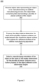
- object data representing an object to be manufactured by an additive manufacturing process is received.
- the object data comprises data representing a plurality of planar surfaces of the object.
- the object data may be in the form of a stereolithography file.
- Such a file may comprise data representing a plurality of planar surfaces comprising triangular segments which combine to form a surface of a three-dimensional object to be manufactured.
- the object data is processed to determine, for each of the plurality of planar surfaces, an angle between the respective planar surface and a plane of a reference surface of the additive manufacturing apparatus.
- the reference surface of the additive manufacturing apparatus may be the platen 108 upon which the object 110 is to be manufactured.
- a manufacturing orientation of the object is selected on the basis of the angles determined for the plurality of planar surface and a further property of the object different to the determined angles, the further property comprising a two-dimensional extent of the object parallel to the plane of the reference surface when the object has a respective orientation.
- a further property of the object may be one or more of: an extent of the object in a direction perpendicular to a plane of a reference of an additive manufacturing apparatus when the object has a respective orientation; and a tensile strength of the object in a direction parallel to the plane of the reference surface when the object has a respective orientation.
- the processor 106 may process the object data to define the plurality of planar surfaces in a first object orientation and determine a first area of the object affected by stair stepping based on the plurality of planar surfaces in the first object orientation.
- the processor may then process the object data to define the plurality of planar surfaces in a second object orientation and determine a second area of the object affected by stair stepping based on the plurality of planar surfaces in the first object orientation.
- the processor may then select the manufacturing orientation of the object (i.e. the orientation with respect to the platen 108) based on which of the first and second areas is lower.
- the processor may process the object data to define the plurality of planar surface in more than two object orientations and may select the manufacturing orientation based on which of a plurality of orientations results in a lowest area affected by stair stepping.
- Figure 3 shows another method 300 of selecting a manufacturing orientation of an object.
- This method may also be implemented by a processor, such as the processor 106 shown in Figure 1 , that processes computer program code that is retrieved from a non-transitory storage medium.
- the method may be implemented by another processor in the apparatus 100 or may be implemented by a processor of a computing device, different from the apparatus 100, the computing device sending instructions to the apparatus 100, for example.
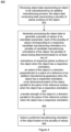
- object data representing an object to be manufactured by an additive manufacturing process is received.
- the object data represents a plurality of planar surfaces of the object.
- a plurality of sets of angles are determined.
- Each of the plurality of sets of angles corresponds to a respective object orientation of the object and comprises a respective plurality of angles.
- Each of the respective plurality of angles is an angle between a respective planar surface of the plurality of planar surfaces and a plane of a reference surface of the apparatus for the respective object orientation.
- a preferred manufacturing orientation of the object is selected on the basis of the determined plurality of sets of angles and a further property of the object different to the determined sets of angles.
- the processor may select the manufacturing orientation based on which of the plurality of sets of angles results in a lowest area affected by stair stepping, as described above with reference to the method 200 shown in Figure 2 .
- the further property comprises a two-dimensional extent of the object parallel to the plane of the reference surface when the object has a respective orientation.
- Yet a further property of the object may be, for example, one or more of: an extent of the object in a direction perpendicular to a plane of a reference of an additive manufacturing apparatus when the object has a respective orientation; and a tensile strength of the object in a direction parallel to the plane of the reference surface when the object has a respective orientation.
- Figure 4 shows another method 400 of selecting a manufacturing orientation of an object.
- This method may also be implemented by a processor, such as the processor 106 shown in Figure 1 , that processes computer program code that is retrieved from a non-transitory storage medium.
- the method may be implemented by another processor in the apparatus 100 or may be implemented by a processor of a computing device, different from the apparatus 100, the computing device sending instructions to the apparatus 100, for example.
- object data representing an object to be manufactured by an additive manufacturing process is received.
- the object data represents a plurality of planar surfaces of the object.
- the object data is iteratively processed to generate a plurality of values of an orientation parameter.
- Each of the plurality of values corresponds to a respective candidate manufacturing orientation of a plurality of candidate manufacturing orientations of the object.
- the plurality of values are determined based on orientations of respective planar surfaces of the object when the object has a respective orientation.
- a preferred manufacturing orientation of the object is selected based on the plurality of values.
- the processor may select the manufacturing orientation based on which of the plurality of values results in a lowest area affected by stair stepping, as described above with reference to the method 200 shown in Figure 2 .
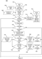
- Figure 5 is a workflow diagram showing an algorithm 500 for selecting a manufacturing orientation of an object.
- the algorithm 500 is a multi-objective algorithm to improve thermal stability of the additive manufacturing apparatus 100, reduce the area of a manufactured object that is affected by stair stepping, and reduce the height of a part that is to be manufactured (thereby reducing material costs and manufacture time).
- the workflow starts at block 502.
- Object data 504 is received at block 506.
- the object data may, for example, be in the form of a such as a stereolithography (.STL) file or a .3mf file.
- rotation vectors for all orientations of the object that are to be evaluated are calculated.
- a data file such as a stereolithography (.STL) file or a .3mf file.
- the object data is processed to orientate or rotate the object to the next orientation to be evaluated at block 520.
- the object data may be processed to define a plurality of planar surfaces in the current orientation.
- the object data may comprise a plurality of triangles that combine to form a surface of a three-dimensional object.
- a determination is made as to whether there are any further planar surfaces (e.g. triangles) in the object data to process.
- an angle between the planar surface and a plane reference surface of the additive manufacturing apparatus is calculated at block 524.
- the plane of the reference surface may be an x-y plane defined by the platen 108 of the additive manufacturing apparatus 100 described above with reference to Figure 1 .
- the algorithm 500 may, for example, determine a vector defining a normal to each triangle and compare that vector with a vector defining a normal to the x-y plane of the platen 108 to determine an angle between the respective vectors for each triangle.
- the stair-stepping angle defines an angle below which the planar surfaces making up the three-dimensional object are likely to exhibit stair stepping. That is, the stair stepping angle defines an angle with the x-y plane of the platen 108 at which stair stepping appears (for a given layer thickness).
- different layer thicknesses may produce stair stepping in different ranges of angles, as the layer thickness represents the resolution of the additive manufacturing apparatus 100 in the z (vertical) direction.
- the algorithm 500 may evaluate the effect of stair stepping for different orientations for a range of layer thicknesses.
- the algorithm 500 may categorize the planar surfaces according to the likelihood that they will exhibit stair stepping. For example, the algorithm 500 may sort the planar surfaces into three categories: "high stair stepping", "low stair stepping” and "no stair stepping". Planar surfaces in the high stair stepping category represent areas of the object where stair stepping is likely to be seen in a manufactured object with high intensity and sharpness. Planar surfaces in the low stair stepping category represent areas of the object where stair stepping is likely to be seen in a manufactured object but with a low intensity and sharpness. For example, planar surfaces in the low stair stepping category may occur in areas on the underside of a manufactured object (in relation to the orientation of the platen 108). Planar surfaces in the no stair stepping category represent areas of the object where stair stepping is likely to be seen in a manufactured object.
- Planar surfaces which satisfy this condition represent planar surfaces in the high stair stepping category (referred to as case 1 in Figure 5 ).
- the area of the planar surface is calculated at block 530.
- the areas of all planar surfaces for which the angle between the planar surface and the reference plane of the additive manufacturing apparatus is less than the first threshold angle are summed.
- Planar surfaces which satisfy this condition represent planar surfaces in the low stair stepping category (referred to as case 2 in Figure 5 ).
- the area of the planar surface is calculated at block 536.
- the areas of all planar surfaces for which the angle between the planar surface and the reference plane of the additive manufacturing apparatus is greater than the second threshold angle are summed.
- the algorithm 500 moves to block 540.
- the algorithm receives weightings for the high stair stepping (case 1) and low stair stepping (case 2) cases and calculates a weighted arithmetic mean of the summed areas.
- Applying the weightings allows the algorithm 500 to place greater importance to the areas with high stair stepping. For example, by giving high stair stepping areas a higher weight in the algorithm 500, the algorithm 500 will choose, between two orientations with the same area affected by stair stepping, the orientation with a higher proportion of low stair stepping areas and a low proportion of high stair stepping areas.
- the weighted arithmetic mean of the summed areas (referred to as a second weighted arithmetic mean) is compared with a weighted arithmetic mean of the summed areas calculated for a previously determined best orientation (referred to as a first weighted arithmetic mean).
- the algorithm 500 determines whether there is a reduction in the area of the object affected by stair stepping if the object is manufactured in a current orientation as compared to a previous best candidate orientation.
- the algorithm may, at block 548, determine if the first and second weighted arithmetic mean areas are equal. In response to determining that the areas are equal, the algorithm 500 may at block 550 determine whether a height of the object in the second orientation (i.e. the vertical extent of the object while being manufactured) is smaller than the height of the object in the first orientation (i.e. the previous best candidate orientation). If the height of the object in the second orientation is smaller than the height of the object in the first orientation, the second orientation may be stored as a new best candidate orientation. If not, then the algorithm 500 may return to block 512 to process the object data again with the object in a new orientation.
- a height of the object in the second orientation i.e. the vertical extent of the object while being manufactured
- the second orientation may be stored as a new best candidate orientation. If not, then the algorithm 500 may return to block 512 to process the object data again with the object in a new orientation.
- the object data may be processed to define the plurality of planar surfaces in a third object orientation (block 520), different to the first object orientation and the second object orientation.
- Blocks 522 to 548 may then be repeated for the new orientation to determine, based on the plurality of planar surfaces in the third object orientation, a third area of the object affected by stair stepping.
- the algorithm may return to block 512.
- the algorithm 500 moves to block 552 where a determination is made as to whether the difference between the first weighted arithmetic mean and the second weighted arithmetic mean is greater than a threshold reduction value 554.
- the threshold reduction value 554 represents a reduction in area affected by stair stepping below which the algorithm 500 considers not significant enough to be beneficial. This purpose of this threshold reduction value 554 is to avoid selection of a manufacturing orientation which provides a small improvement in terms of reducing an amount of stair stepping but at a cost of a large increase in the height of the object during manufacture (and the associated increase in material costs and manufacture time).
- the algorithm moves to block 556 where a determination is made as to whether a two-dimensional extent of the object parallel to the plane of the reference surface is less than an area threshold 558.
- the area threshold 558 defines a maximum area of the additive manufacturing apparatus that is to be used for manufacture of the object. The purpose of this area threshold 558 is to ensure the thermal stability of the manufacture process during manufacture of the object by ensuring that the area of the platen 108 that is used (i.e. on which layers of the three-dimensional object are build) is within the capability of the apparatus to uniformly fuse build material.
- the current orientation i.e. the second object orientation
- the current orientation is stored in memory as a new best candidate object orientation.
- the algorithm 500 moves to block 560.
- a determination is made as to whether the height of the object (in the current, second, orientation) is less than a height threshold value 562.
- the purpose of this is to enable the possibility for the algorithm 500 to select candidate orientations which may not provide a large improvement over other candidate orientations in terms of reducing stair stepping but may provide a significant reduction in material costs and manufacture time by reducing the overall height of the object during manufacture. Accordingly, in response to determining at block 560 that the height (i.e. an extent of the object in a direction perpendicular to the plane of the reference surface) is less than the height threshold 562, the algorithm 500 may move to block 556 described above.
- the algorithm 500 may omit certain blocks.
- the algorithm 500 may not necessarily consider the angle between the planar surface and the reference plane of the additive manufacturing apparatus by, for example, omitting blocks 522 to 552 and progressing directly from block 520 to block 560.
- the algorithm 500 may be amended to omit block 560.
- the algorithm 500 may be amended to omit block 556.
- the algorithm may calculate a value related to a tensile strength of the manufactured object for each respective object orientation and select a manufacturing orientation of the object partly on the basis of the values of tensile strength.
- the tensile strength of a manufactured object may be higher in the plane in which the build material is deposited (i.e. the x-y plane) and the algorithm 500 may accordingly select the manufacturing orientation to increase the tensile strength.
- the algorithm 500 may also receive data indicating processes that are to be applied to the object after the additive manufacturing process. Such post-process may affect the final dimensions of the object and so by considering the post-processing at the design stage, the algorithm 500 can compensate for changes to the dimensions of the object caused by post-processes.
- the algorithm 500 may be able to receive data input by the designer to specify that, after the additive manufacturing process, the part will receive a treatment that will add an additional thickness to the finished object.
- the designer may specify to the algorithm 500 that the part is to be painted and may be able to specify a thickness of the paint (for example 0.2 mm).
- the algorithm 500 may then be arranged to compensate for the painting process by applying an offset of 0.2 mm to all external surfaces of the object.
- the designer may specify that the part is to be electroplated and may be able to specify that the electroplating process will add a thickness of, for example, 0.1 mm.
- the algorithm 500 may then be arranged to compensate for the painting process by applying an offset of 0.1 mm to all external surfaces of the object.
- the designer may specify that the part is to be dyed following the additive manufacture process and may specify that as a result of water absorption during the dying process the object will expand by a certain amount (for example 0.05 %).
- the algorithm 500 may then be arranged to compensate for the dyeing process by scaling the dimensions of the object by a corresponding amount.
- the object may be subjected to processes after the additive manufacturing process, which reduce the dimensions of the object.
- the object may be subjected to a tumbler process (for example, to remove burrs or other unwanted surface features).
- the designer may specify that the part is to be subjected to such a process and may specify an expected reduction in the dimensions of the object (for example, that the external surface with be reduced in thickness by 0.05 mm.
- the algorithm 500 may then be arranged to apply an offset increase in the dimensions of the object to compensate for the expected reduction.
- Certain methods and systems as described herein may be implemented by a processor that processes computer program code that is retrieved from a non-transitory storage medium.
- the method 200, the method 300 and the method 400 described above with reference to Figures 2 , 3 , and 4 may be implemented by computer program code that is implemented by a computing device, including a processor of a computing system embedded in a printing device.
- Figure 6 shows an example of a processing device 600 comprising a machine-readable storage medium 602 coupled to a processor 604.
- the processing device 604 may comprise a stand-alone computing device, such as a desktop computer or server communicatively coupled to an imaging device; in other cases the processing device 604 may comprise part of an additive manufacturing apparatus, such as the manufacturing apparatus 100 described above with reference to Figure 1 .
- the machine-readable medium 602 can be any medium that can contain, store, or maintain programs and data for use by or in connection with an instruction execution system.
- Machine-readable media can comprise any one of many physical media such as, for example, electronic, magnetic, optical, electromagnetic, or semiconductor media. More specific examples of suitable machine-readable media include, but are not limited to, a hard drive, a random access memory (RAM), a read-only memory (ROM), an erasable programmable read-only memory, or a portable disc.
- the machine-readable storage medium 602 comprises program code to implement the method 200 described above with reference to Figure 2 . However, the program code may be to implement any of the methods described above.
- object data representing an object to be manufactured by an additive manufacturing process is received.
- the object data comprises data representing a plurality of planar surfaces of the object.
- the object data may be in the form of a stereolithography file.
- Such a file may comprise data representing a plurality of triangular segments which combine to form a surface of a three-dimensional object to be manufactured.
- the object data is processed to determine, for each of the plurality of planar surfaces, an angle between the respective planar surface and a plane of a reference surface of the additive manufacturing apparatus.
- the reference surface of the additive manufacturing apparatus may be the platen 108 upon which the object 110 is to be manufactured.
- a manufacturing orientation of the object is selected on the basis of the angles determined for the plurality of planar surface and a further property of the object different to the determined angles.
- the further property comprises a two-dimensional extent of the object parallel to the plane of the reference surface when the object has a respective orientation.
- a further property of the object may be one or more of: an extent of the object in a direction perpendicular to a plane of a reference of an additive manufacturing apparatus when the object has a respective orientation; and a tensile strength of the object in a direction parallel to the plane of the reference surface when the object has a respective orientation.
- the processor may process the object data to define the plurality of planar surfaces in a first object orientation and determine a first area of the object affected by stair stepping based on the plurality of planar surfaces in the first object orientation.
- the processor may then process the object data to define the plurality of planar surfaces in a second object orientation and determine a second area of the object affected by stair stepping based on the plurality of planar surfaces in the first object orientation.
- the processor may then select the manufacturing orientation of the object (i.e. the orientation with respect to the platen 108) based on which of the first and second areas is lower.
- the processor may process the object data to define the plurality of planar surface is more than two object orientations and may select the manufacturing orientation based on which of a plurality of orientations results in a lowest area affected by stair stepping.
- each of the properties based on which the algorithm is selected may be assigned a weight corresponding to its relevant importance.
- This weight may be, for example, reflected as threshold values such as the various thresholds defined in relation to the algorithm 500 described above with reference to Figure 5 .
- the preceding description has been presented to illustrate and describe examples of the principles described. This description is not intended to be exhaustive or to limit these principles to any precise form disclosed. Many modifications and variations are possible in light of the above teaching.
- the preceding description has been presented with reference to an additive manufacturing apparatus that uses a fusing agent that absorbs electromagnetic radiation to cause build material to fuse.
- the additive manufacturing apparatus may use no fusing agent and may instead fuse build material by directly applying focused energy from, for example, a laser beam or an electron beam.
Landscapes
- Chemical & Material Sciences (AREA)
- Engineering & Computer Science (AREA)
- Materials Engineering (AREA)
- Manufacturing & Machinery (AREA)
- Physics & Mathematics (AREA)
- Mechanical Engineering (AREA)
- Optics & Photonics (AREA)
Claims (15)
- Nichtflüchtiges maschinenlesbares Speicherungsmedium (602), das Anweisungen speichert, die, wenn sie durch einen Prozessor (106, 604) ausgeführt werden, den Prozessor zu Folgendem veranlassen:Empfangen (202, 606) von Objektdaten, die einem Objekt entsprechen, das dazu dient, durch einen additiven Fertigungsvorgang gefertigt zu werden, das ein Verwenden eines Schmelzmittels umfasst, das elektromagnetische Strahlung absorbiert, um ein Baumaterial zu veranlassen, zu verschmelzen, wobei die Objektdaten Daten umfassen, die einer Vielzahl von ebenen Oberflächen des Objekts entsprechen;Verarbeiten (204, 608) der Objektdaten, um für jede der Vielzahl von ebenen Oberflächen einen Winkel zwischen der jeweiligen ebenen Oberfläche und einer Ebene einer Referenzoberfläche einer additiven Fertigungsvorrichtung zu bestimmen; undAuswählen (206, 610) einer Fertigungsorientierung des Objekts auf der Basis der Winkel, die für die Vielzahl von ebenen Oberflächen bestimmt werden, und einer weiteren Eigenschaft des Objekts, die sich von den bestimmten Winkeln unterscheidet; wobei die weitere Eigenschaft des Objekts eine zweidimensionale Ausdehnung des Objekts parallel zu der Ebene der Referenzoberfläche umfasst, wenn das Objekt eine jeweilige Orientierung aufweist.
- Nichtflüchtiges maschinenlesbares Speicherungsmedium nach Anspruch 1, wobei die weitere Eigenschaft des Objekts eines oder mehrere der Folgenden umfasst:eine Ausdehnung des Objekts in einer Richtung senkrecht zu einer Ebene einer Referenz einer additiven Fertigungsvorrichtung, wenn das Objekt eine jeweilige Orientierung aufweist;
; undeine Zugfestigkeit des Objekts in einer Richtung parallel zu der Ebene der Referenzoberfläche, wenn das Objekt eine jeweilige Orientierung aufweist. - Nichtflüchtiges maschinenlesbares Speicherungsmedium nach Anspruch 1, das Anweisungen speichert, die, wenn sie durch einen Prozessor ausgeführt werden, den Prozessor zu Folgendem veranlassen:Verarbeiten der Objektdaten, um die Vielzahl von ebenen Oberflächen in einer ersten Objektorientierung zu definieren;Bestimmen, auf der Basis der Vielzahl von ebenen Oberflächen in der ersten Objektorientierung, eines ersten Bereichs des Objekts, der durch einen Treppeneffekt beeinflusst wird;Verarbeiten der Objektdaten, um die Vielzahl von ebenen Oberflächen in einer zweiten Objektorientierung zu definieren, die sich von der ersten Objektorientierung unterscheidet;Bestimmen, auf der Basis der Vielzahl von ebenen Oberflächen in der zweiten Objektorientierung, eines zweiten Bereichs des Objekts, der durch einen Treppeneffekt beeinflusst wird; undAuswählen der Fertigungsorientierung des Objekts auf der Basis darauf, welcher des ersten und des zweiten Bereichs niedriger ist.
- Nichtflüchtiges, maschinenlesbares Speicherungsmedium nach Anspruch 3, das Anweisungen speichert, die, wenn sie durch einen Prozessor ausgeführt werden, den Prozessor zu Folgendem veranlassen:Bestimmen, für jede der Vielzahl von ebenen Oberflächen, ob der Winkel zwischen der jeweiligen ebenen Oberfläche und der Ebene der Referenzoberfläche der additiven Fertigungsvorrichtung kleiner als ein erster Schwellenwinkel ist oder größer als ein zweiter Schwellenwinkel ist, wobei der zweite Schwellenwinkel gleich 180 Grad minus dem ersten Schwellenwinkel ist; undSumme der Bereiche der Vielzahl von ebenen Oberflächen, für die bestimmt wird, dass der Winkel kleiner als der erste Schwellenwinkel oder größer als ein zweiter Schwellenwinkel ist.
- Nichtflüchtiges, maschinenlesbares Speicherungsmedium nach Anspruch 4, das Anweisungen speichert, die, wenn sie durch einen Prozessor ausgeführt werden, den Prozessor zu Folgendem veranlassen:Aufbringen einer ersten Gewichtung auf Bereiche der Vielzahl von ebenen Oberflächen, für die der bestimmte Winkel kleiner als der erste Schwellenwinkel ist, und eine zweite Gewichtung auf Bereiche der Vielzahl von ebenen Oberflächen, für die der bestimmte Winkel größer als der zweite Schwellenwinkel ist; undBerechnen eines gewichteten Mittelwerts der summierten Bereiche der Vielzahl von ebenen Oberflächen, für die bestimmt wird, dass der Winkel kleiner als der erste Schwellenwinkel oder größer als ein zweiter Schwellenwinkel ist.
- Nichtflüchtiges, maschinenlesbares Speicherungsmedium nach Anspruch 4, das Anweisungen speichert, die, wenn sie durch einen Prozessor ausgeführt werden, den Prozessor zu Folgendem veranlassen:Berechnen eines ersten gewichteten Mittelwerts des Bereichs der Vielzahl von ebenen Oberflächen, für den, in einer ersten Objektorientierung, bestimmt wird, dass der Winkel kleiner als der erste Schwellenwinkel oder größer als der zweite Schwellenwinkel ist;Berechnen eines zweiten gewichteten Mittelwerts des Bereichs der Vielzahl von ebenen Oberflächen, für den, in einer zweiten Objektorientierung, bestimmt wird, dass der Winkel kleiner als der erste Schwellenwinkel oder größer als der zweite Schwellenwinkel ist; undVergleichen des ersten gewichteten Mittelwerts mit dem zweiten gewichteten Mittelwert.
- Nichtflüchtiges, maschinenlesbares Speicherungsmedium nach Anspruch 6, das Anweisungen speichert, die, wenn sie durch einen Prozessor ausgeführt werden, den Prozessor zu Folgendem veranlassen:als Reaktion auf ein Bestimmen, dass der zweite gewichtete Mittelwert größer als der erste gewichtete Mittelwert ist, Verarbeiten der Objektdaten, um die Vielzahl von ebenen Oberflächen in einer dritten Objektorientierung zu definieren, die sich von der ersten Objektorientierung und der zweiten Objektorientierung unterscheidet;Bestimmen, auf der Basis der Vielzahl von ebenen Oberflächen in der dritten Objektorientierung, eines dritten Bereichs des Objekts, der durch einen Treppeneffekt beeinflusst wird; undSpeichern einer Kandidatenobjektorientierung des Objekts in einem Speicher auf der Basis darauf, welcher des ersten und des dritten Bereichs niedriger ist.
- Nichtflüchtiges, maschinenlesbares Speicherungsmedium nach Anspruch 6, das Anweisungen speichert, die, wenn sie durch einen Prozessor in ausgeführt werden, den Prozessor zu Folgendem veranlassen:
als Reaktion auf ein Bestimmen, dass der zweite gewichtete Mittelwert kleiner als der erste gewichtete Mittelwert ist, Bestimmen, ob der Unterschied zwischen dem ersten gewichteten Mittelwert und dem zweiten gewichteten Mittelwert größer als ein Schwellenreduzierungswert ist. - Nichtflüchtiges, maschinenlesbares Speicherungsmedium nach Anspruch 8, das Anweisungen speichert, die, wenn sie durch einen Prozessor ausgeführt werden, den Prozessor zu Folgendem veranlassen:als Reaktion auf ein Bestimmen, dass der Unterschied zwischen dem ersten gewichteten Mittelwert und dem zweiten gewichteten Mittelwert größer als der Schwellenreduzierungswert ist, Bestimmen, ob eine zweidimensionale Ausdehnung des Objekts parallel zu der Ebene der Referenzoberfläche kleiner als eine Bereichsschwelle ist; undals Reaktion auf ein Bestimmen, dass die zweidimensionale Ausdehnung des Objekts parallel zu der Ebene der Referenzoberfläche kleiner als die Bereichsschwelle ist, Speichern einer Kandidatenobjektorientierung, die mit der zweiten Objektorientierung übereinstimmt, in einem Speicher.
- Nichtflüchtiges, maschinenlesbares Speicherungsmedium nach Anspruch 8, das Anweisungen speichert, die, wenn sie durch einen Prozessor ausgeführt werden, den Prozessor zu Folgendem veranlassen:als Reaktion auf ein Bestimmen, dass der Unterschied zwischen dem ersten gewichteten Mittelwert und dem zweiten gewichteten Mittelwert kleiner als oder gleich dem Schwellenreduktionswert ist, Bestimmen, ob eine Ausdehnung des Objekts in einer Richtung senkrecht zu der Ebene der Referenzoberfläche kleiner als eine Höhenschwelle ist; undals Reaktion auf ein Bestimmen, dass die Ausdehnung des Objekts in einer Richtung senkrecht zu der Ebene der Referenzoberfläche kleiner als eine Höhenschwelle ist, Bestimmen, ob eine zweidimensionale Ausdehnung des Objekts parallel zu der Ebene der Referenzoberfläche kleiner als eine Bereichsschwelle ist; undals Reaktion auf ein Bestimmen, dass die zweidimensionale Ausdehnung des Objekts parallel zu der Ebene der Referenzoberfläche kleiner als die Bereichsschwelle ist, Speichern einer Kandidatenobjektorientierung, die mit der zweiten Objektorientierung übereinstimmt, in einem Speicher.
- Nichtflüchtiges maschinenlesbares Speicherungsmedium nach Anspruch 1, das Anweisungen speichert, die, wenn sie durch einen Prozessor ausgeführt werden, den Prozessor zu Folgendem veranlassen:Empfangen von Nachverarbeitungsdaten, die einen Vorgang angeben, der dazu dient, auf das Objekt nach einem additiven Fertigungsvorgang aufgebracht zu werden; undModifizieren der Objektdaten, um eine oder mehrere Abmessungen des Objekts zu modifizieren, das dazu dient, durch eine additive Fertigungsvorrichtung auf der Basis der Nachverarbeitungsdaten ausgebildet zu werden.
- Vorrichtung, um ein dreidimensionales Objekt zu produzieren, wobei die Vorrichtung einen Prozessor (106, 604) und einen Schmelzer umfasst, um elektromagnetische Strahlung (118) aufzubringen, wobei der Prozessor für Folgendes konfiguriert ist:Empfangen (302) von Objektdaten, die einem Objekt entsprechen, das dazu dient, durch einen additiven Fertigungsvorgang gefertigt zu werden, wobei die Objektdaten Daten umfassen, die einer Vielzahl von ebenen Oberflächen des Objekts entsprechen;Bestimmen (304) einer Vielzahl von Winkelsätzen, wobei jeder der Vielzahl von Winkelsätzen mit einer jeweiligen Objektorientierung des Objekts übereinstimmt und eine jeweilige Vielzahl von Winkeln umfasst, wobei jeder der jeweiligen Vielzahl von Winkeln ein Winkel zwischen einer jeweiligen ebenen Oberfläche der Vielzahl von ebenen Oberflächen und einer Ebene einer Referenzoberfläche der Vorrichtung für die jeweilige Objektorientierung ist; undAuswählen (306) einer Fertigungsorientierung des Objekts auf der Basis der bestimmten Vielzahl von Winkelsätzen und einer weiteren Eigenschaft des Objekts, die sich von den bestimmten Winkelsätzen unterscheidet, wodurch die weitere Eigenschaft des Objekts eine zweidimensionale Ausdehnung des Objekts parallel zu der Ebene der Referenzoberfläche umfasst, wenn das Objekt eine jeweilige Orientierung aufweist.
- Verfahren zum Auswählen einer Fertigungsorientierung eines Objekts, das dazu dient, durch eine additive Fertigungsvorrichtung ausgebildet zu werden, die einen Prozessor (106, 604) und einen Schmelzer umfasst, um elektromagnetische Strahlung (118) aufzubringen, wobei das Verfahren Folgendes umfasst:Empfangen (402), an dem Prozessor, von Objektdaten, die einem Objekt entsprechen, das dazu dient, durch einen additiven Fertigungsvorgang gefertigt zu werden, das dein Verwenden eines Schmelzmittels umfasst, das elektromagnetische Strahlung absorbiert, um ein Baumaterial zu veranlassen, zu verschmelzen, wobei die Objektdaten Daten umfassen, die einer Vielzahl von ebenen Oberflächen des Objekts entsprechen;iteratives Verarbeiten (404), durch den Prozessor, der Objektdaten, um eine Vielzahl von Werten eines Orientierungsparameters zu erzeugen, wobei mit jeder der Vielzahl von Werten einer jeweiligen Kandidatenfertigungsorientierung einer Vielzahl von Kandidatenfertigungsorientierungen des Objekts übereinstimmt, wobei die Vielzahl von Werten auf der Basis einer zweidimensionalen Ausdehnung des Objekts parallel zu der Ebene der Referenzoberfläche bestimmt werden, wenn das Objekt eine jeweilige Orientierung aufweist, und auf der Basis von mindestens einem von:Orientierungen jeweiliger ebenen Oberflächen des Objekts, wenn das Objekt eine jeweilige Orientierung aufweist;eine Ausdehnung des Objekts in einer Richtung senkrecht zu einer Ebene einer Referenz einer additiven Fertigungsvorrichtung, wenn das Objekt eine jeweilige Orientierung aufweist; undeine Zugfestigkeit des Objekts in einer Richtung parallel zu der Ebene der Referenzoberfläche, wenn das Objekt eine jeweilige Orientierung aufweist; undAuswählen (406) einer bevorzugten Fertigungsorientierung des Objekts auf der Basis der mehreren Werte.
- Verfahren nach Anspruch 13, das Folgendes umfasst:Empfangen von Nachverarbeitungsdaten, die einen Vorgang angeben, der dazu dient, auf das Objekt nach dem additiven Fertigungsvorgang aufgebracht zu werden; undModifizieren der Objektdaten, um eine oder mehrere Dimensionen des Objekts zu modifizieren, das dazu dient, durch die additive Fertigungsvorrichtung auf der Basis der Nachverarbeitungsdaten ausgebildet zu werden.
- Verfahren nach Anspruch 14, wobei der Vorgang, der dazu dient, nach einem additiven Fertigungsvorgang auf das Objekt aufgebracht zu werden, eines oder mehrere der Folgenden umfasst:einen Lackiervorgang;einen Galvanisiervorgang;einen Färbevorgang; undeinen Trommelvorgang.
Applications Claiming Priority (1)
| Application Number | Priority Date | Filing Date | Title |
|---|---|---|---|
| PCT/US2018/044499 WO2020027789A1 (en) | 2018-07-31 | 2018-07-31 | Three-dimensional object production |
Publications (3)
| Publication Number | Publication Date |
|---|---|
| EP3774296A1 EP3774296A1 (de) | 2021-02-17 |
| EP3774296A4 EP3774296A4 (de) | 2021-10-20 |
| EP3774296B1 true EP3774296B1 (de) | 2024-01-10 |
Family
ID=69231968
Family Applications (1)
| Application Number | Title | Priority Date | Filing Date |
|---|---|---|---|
| EP18928828.5A Active EP3774296B1 (de) | 2018-07-31 | 2018-07-31 | Herstellung eines dreidimensionalen objekts |
Country Status (4)
| Country | Link |
|---|---|
| US (1) | US11383447B2 (de) |
| EP (1) | EP3774296B1 (de) |
| CN (1) | CN112166025B (de) |
| WO (1) | WO2020027789A1 (de) |
Families Citing this family (1)
| Publication number | Priority date | Publication date | Assignee | Title |
|---|---|---|---|---|
| US20230102130A1 (en) * | 2020-03-20 | 2023-03-30 | Hewlett-Packard Development Company, L.P. | Print job processing |
Family Cites Families (17)
| Publication number | Priority date | Publication date | Assignee | Title |
|---|---|---|---|---|
| US6492651B2 (en) * | 2001-02-08 | 2002-12-10 | 3D Systems, Inc. | Surface scanning system for selective deposition modeling |
| US20070085241A1 (en) | 2005-10-14 | 2007-04-19 | Northrop Grumman Corporation | High density performance process |
| US7403833B2 (en) * | 2006-04-03 | 2008-07-22 | Stratasys, Inc. | Method for optimizing spatial orientations of computer-aided design models |
| TWI601627B (zh) | 2014-03-17 | 2017-10-11 | 三緯國際立體列印科技股份有限公司 | 立體列印方法、立體列印裝置及電子裝置 |
| US9827717B2 (en) | 2014-08-15 | 2017-11-28 | University Of Southern California | Statistical predictive modeling and compensation of geometric deviations of 3D printed products |
| US10046522B2 (en) * | 2015-02-26 | 2018-08-14 | Stratasys, Inc. | Surface angle model evaluation process for additive manufacturing |
| US10336000B2 (en) | 2015-03-13 | 2019-07-02 | Carbon, Inc. | Methods, systems, and computer program products for determining orientation and fabrication parameters used in three-dimensional (3D) continuous liquid interface printing (CLIP) systems, and related printers |
| WO2016169620A1 (en) * | 2015-04-24 | 2016-10-27 | Hewlett-Packard Development Company, Lp | Method for setting printing properties of a three-dimensional object for additive manufacturing process |
| US10474134B2 (en) | 2015-04-29 | 2019-11-12 | University Of Southern California | Systems and methods for compensating for 3D shape deviations in additive manufacturing |
| US10926528B2 (en) | 2015-07-30 | 2021-02-23 | Hewlett-Packard Development Company, L.P. | Color calibration for three-dimensional printing |
| US10761497B2 (en) | 2016-01-14 | 2020-09-01 | Microsoft Technology Licensing, Llc | Printing 3D objects with automatic dimensional accuracy compensation |
| US9919360B2 (en) | 2016-02-18 | 2018-03-20 | Velo3D, Inc. | Accurate three-dimensional printing |
| JP6461846B2 (ja) | 2016-03-24 | 2019-01-30 | 株式会社東芝 | 積層造形装置、及びプログラム |
| WO2018064349A1 (en) | 2016-09-30 | 2018-04-05 | Velo3D, Inc. | Three-dimensional objects and their formation |
| ES2911260T3 (es) * | 2016-10-07 | 2022-05-18 | Airbus Operations Sl | Sistema y método de curado de piezas de material compuesto de matriz polimérica en procesos de fabricación y de reparación |
| EP3305510A1 (de) | 2016-10-10 | 2018-04-11 | Acondicionamiento Tarrasense | Verfahren zum polieren von durch generative fertigung oder 3d-drucktechniken hergestellten polyamidobjekten |
| US10409264B2 (en) | 2016-10-27 | 2019-09-10 | Voodoo Manufacturing, Inc. | Fabrication of three-dimensional part with two-dimensional image applied thereon |
-
2018
- 2018-07-31 EP EP18928828.5A patent/EP3774296B1/de active Active
- 2018-07-31 US US16/605,207 patent/US11383447B2/en active Active
- 2018-07-31 WO PCT/US2018/044499 patent/WO2020027789A1/en not_active Ceased
- 2018-07-31 CN CN201880093498.7A patent/CN112166025B/zh active Active
Also Published As
| Publication number | Publication date |
|---|---|
| CN112166025B (zh) | 2023-06-16 |
| EP3774296A4 (de) | 2021-10-20 |
| US20210331401A1 (en) | 2021-10-28 |
| CN112166025A (zh) | 2021-01-01 |
| EP3774296A1 (de) | 2021-02-17 |
| US11383447B2 (en) | 2022-07-12 |
| WO2020027789A1 (en) | 2020-02-06 |
Similar Documents
| Publication | Publication Date | Title |
|---|---|---|
| US11651122B2 (en) | Machine learning for additive manufacturing | |
| US11364687B2 (en) | Compensating for dimensional variation in 3D printing | |
| US11964436B2 (en) | Patterns on objects in additive manufacturing | |
| US20250326183A1 (en) | Coloured objects in additive manufacturing | |
| EP3774296B1 (de) | Herstellung eines dreidimensionalen objekts | |
| US20210331403A1 (en) | Segmenting object model data at first and second resolutions | |
| US12197187B2 (en) | Geometrical transformations in additive manufacturing | |
| WO2023122004A1 (en) | Machine learning for additive manufacturing | |
| US20230052299A1 (en) | Surface roughness application | |
| US12220869B2 (en) | Object orientation and/or position for additive manufacturing | |
| US20220016845A1 (en) | Geometrical compensation in additive manufacturing | |
| US20210394447A1 (en) | Coloured object generation | |
| US11780170B2 (en) | Fusing three dimensional (3D) parts | |
| US12544981B2 (en) | Flexibility of features of an object to be additively manufactured | |
| US20220024126A1 (en) | Additive manufacturing process using colorant and laser fusion | |
| WO2020068059A1 (en) | Evaluating candidate virtual build volumes | |
| CN114555341A (zh) | 确定增材制造中的构建参数 | |
| WO2021230858A1 (en) | Identifying interior surfaces |
Legal Events
| Date | Code | Title | Description |
|---|---|---|---|
| STAA | Information on the status of an ep patent application or granted ep patent |
Free format text: STATUS: THE INTERNATIONAL PUBLICATION HAS BEEN MADE |
|
| PUAI | Public reference made under article 153(3) epc to a published international application that has entered the european phase |
Free format text: ORIGINAL CODE: 0009012 |
|
| STAA | Information on the status of an ep patent application or granted ep patent |
Free format text: STATUS: REQUEST FOR EXAMINATION WAS MADE |
|
| 17P | Request for examination filed |
Effective date: 20201029 |
|
| AK | Designated contracting states |
Kind code of ref document: A1 Designated state(s): AL AT BE BG CH CY CZ DE DK EE ES FI FR GB GR HR HU IE IS IT LI LT LU LV MC MK MT NL NO PL PT RO RS SE SI SK SM TR |
|
| AX | Request for extension of the european patent |
Extension state: BA ME |
|
| A4 | Supplementary search report drawn up and despatched |
Effective date: 20210920 |
|
| RIC1 | Information provided on ipc code assigned before grant |
Ipc: B33Y 40/20 20200101ALI20210914BHEP Ipc: B22F 10/30 20210101ALI20210914BHEP Ipc: B29C 64/386 20170101ALI20210914BHEP Ipc: B33Y 30/00 20150101ALI20210914BHEP Ipc: B33Y 50/00 20150101ALI20210914BHEP Ipc: B29C 64/20 20170101ALI20210914BHEP Ipc: B29C 64/393 20170101AFI20210914BHEP |
|
| DAV | Request for validation of the european patent (deleted) | ||
| DAX | Request for extension of the european patent (deleted) | ||
| REG | Reference to a national code |
Ref country code: DE Ref legal event code: R079 Free format text: PREVIOUS MAIN CLASS: B29C0064393000 Ipc: B29C0064386000 Ref document number: 602018064144 Country of ref document: DE |
|
| RIC1 | Information provided on ipc code assigned before grant |
Ipc: B22F 10/28 20210101ALN20230712BHEP Ipc: B33Y 40/00 20200101ALN20230712BHEP Ipc: B33Y 40/10 20200101ALN20230712BHEP Ipc: B33Y 30/00 20150101ALN20230712BHEP Ipc: B22F 10/85 20210101ALI20230712BHEP Ipc: B33Y 50/00 20150101ALI20230712BHEP Ipc: B33Y 40/20 20200101ALI20230712BHEP Ipc: B29C 64/393 20170101ALI20230712BHEP Ipc: B29C 64/386 20170101AFI20230712BHEP |
|
| RIC1 | Information provided on ipc code assigned before grant |
Ipc: B22F 10/28 20210101ALN20230804BHEP Ipc: B33Y 40/00 20200101ALN20230804BHEP Ipc: B33Y 40/10 20200101ALN20230804BHEP Ipc: B33Y 30/00 20150101ALN20230804BHEP Ipc: B22F 10/85 20210101ALI20230804BHEP Ipc: B33Y 50/00 20150101ALI20230804BHEP Ipc: B33Y 40/20 20200101ALI20230804BHEP Ipc: B29C 64/393 20170101ALI20230804BHEP Ipc: B29C 64/386 20170101AFI20230804BHEP |
|
| GRAP | Despatch of communication of intention to grant a patent |
Free format text: ORIGINAL CODE: EPIDOSNIGR1 |
|
| STAA | Information on the status of an ep patent application or granted ep patent |
Free format text: STATUS: GRANT OF PATENT IS INTENDED |
|
| RIC1 | Information provided on ipc code assigned before grant |
Ipc: B22F 10/28 20210101ALN20230911BHEP Ipc: B33Y 40/00 20200101ALN20230911BHEP Ipc: B33Y 40/10 20200101ALN20230911BHEP Ipc: B33Y 30/00 20150101ALN20230911BHEP Ipc: B22F 10/85 20210101ALI20230911BHEP Ipc: B33Y 50/00 20150101ALI20230911BHEP Ipc: B33Y 40/20 20200101ALI20230911BHEP Ipc: B29C 64/393 20170101ALI20230911BHEP Ipc: B29C 64/386 20170101AFI20230911BHEP |
|
| INTG | Intention to grant announced |
Effective date: 20230925 |
|
| GRAS | Grant fee paid |
Free format text: ORIGINAL CODE: EPIDOSNIGR3 |
|
| GRAA | (expected) grant |
Free format text: ORIGINAL CODE: 0009210 |
|
| STAA | Information on the status of an ep patent application or granted ep patent |
Free format text: STATUS: THE PATENT HAS BEEN GRANTED |
|
| AK | Designated contracting states |
Kind code of ref document: B1 Designated state(s): AL AT BE BG CH CY CZ DE DK EE ES FI FR GB GR HR HU IE IS IT LI LT LU LV MC MK MT NL NO PL PT RO RS SE SI SK SM TR |
|
| REG | Reference to a national code |
Ref country code: GB Ref legal event code: FG4D |
|
| REG | Reference to a national code |
Ref country code: CH Ref legal event code: EP |
|
| REG | Reference to a national code |
Ref country code: DE Ref legal event code: R096 Ref document number: 602018064144 Country of ref document: DE |
|
| REG | Reference to a national code |
Ref country code: IE Ref legal event code: FG4D |
|
| REG | Reference to a national code |
Ref country code: LT Ref legal event code: MG9D |
|
| REG | Reference to a national code |
Ref country code: NL Ref legal event code: MP Effective date: 20240110 |
|
| REG | Reference to a national code |
Ref country code: AT Ref legal event code: MK05 Ref document number: 1648587 Country of ref document: AT Kind code of ref document: T Effective date: 20240110 |
|
| PG25 | Lapsed in a contracting state [announced via postgrant information from national office to epo] |
Ref country code: NL Free format text: LAPSE BECAUSE OF FAILURE TO SUBMIT A TRANSLATION OF THE DESCRIPTION OR TO PAY THE FEE WITHIN THE PRESCRIBED TIME-LIMIT Effective date: 20240110 |
|
| PG25 | Lapsed in a contracting state [announced via postgrant information from national office to epo] |
Ref country code: NL Free format text: LAPSE BECAUSE OF FAILURE TO SUBMIT A TRANSLATION OF THE DESCRIPTION OR TO PAY THE FEE WITHIN THE PRESCRIBED TIME-LIMIT Effective date: 20240110 |
|
| PG25 | Lapsed in a contracting state [announced via postgrant information from national office to epo] |
Ref country code: IS Free format text: LAPSE BECAUSE OF FAILURE TO SUBMIT A TRANSLATION OF THE DESCRIPTION OR TO PAY THE FEE WITHIN THE PRESCRIBED TIME-LIMIT Effective date: 20240510 |
|
| PG25 | Lapsed in a contracting state [announced via postgrant information from national office to epo] |
Ref country code: LT Free format text: LAPSE BECAUSE OF FAILURE TO SUBMIT A TRANSLATION OF THE DESCRIPTION OR TO PAY THE FEE WITHIN THE PRESCRIBED TIME-LIMIT Effective date: 20240110 |
|
| PG25 | Lapsed in a contracting state [announced via postgrant information from national office to epo] |
Ref country code: GR Free format text: LAPSE BECAUSE OF FAILURE TO SUBMIT A TRANSLATION OF THE DESCRIPTION OR TO PAY THE FEE WITHIN THE PRESCRIBED TIME-LIMIT Effective date: 20240411 |
|
| PG25 | Lapsed in a contracting state [announced via postgrant information from national office to epo] |
Ref country code: HR Free format text: LAPSE BECAUSE OF FAILURE TO SUBMIT A TRANSLATION OF THE DESCRIPTION OR TO PAY THE FEE WITHIN THE PRESCRIBED TIME-LIMIT Effective date: 20240110 Ref country code: RS Free format text: LAPSE BECAUSE OF FAILURE TO SUBMIT A TRANSLATION OF THE DESCRIPTION OR TO PAY THE FEE WITHIN THE PRESCRIBED TIME-LIMIT Effective date: 20240410 |
|
| PG25 | Lapsed in a contracting state [announced via postgrant information from national office to epo] |
Ref country code: ES Free format text: LAPSE BECAUSE OF FAILURE TO SUBMIT A TRANSLATION OF THE DESCRIPTION OR TO PAY THE FEE WITHIN THE PRESCRIBED TIME-LIMIT Effective date: 20240110 |
|
| PG25 | Lapsed in a contracting state [announced via postgrant information from national office to epo] |
Ref country code: AT Free format text: LAPSE BECAUSE OF FAILURE TO SUBMIT A TRANSLATION OF THE DESCRIPTION OR TO PAY THE FEE WITHIN THE PRESCRIBED TIME-LIMIT Effective date: 20240110 |
|
| PG25 | Lapsed in a contracting state [announced via postgrant information from national office to epo] |
Ref country code: RS Free format text: LAPSE BECAUSE OF FAILURE TO SUBMIT A TRANSLATION OF THE DESCRIPTION OR TO PAY THE FEE WITHIN THE PRESCRIBED TIME-LIMIT Effective date: 20240410 Ref country code: NO Free format text: LAPSE BECAUSE OF FAILURE TO SUBMIT A TRANSLATION OF THE DESCRIPTION OR TO PAY THE FEE WITHIN THE PRESCRIBED TIME-LIMIT Effective date: 20240410 Ref country code: LT Free format text: LAPSE BECAUSE OF FAILURE TO SUBMIT A TRANSLATION OF THE DESCRIPTION OR TO PAY THE FEE WITHIN THE PRESCRIBED TIME-LIMIT Effective date: 20240110 Ref country code: IS Free format text: LAPSE BECAUSE OF FAILURE TO SUBMIT A TRANSLATION OF THE DESCRIPTION OR TO PAY THE FEE WITHIN THE PRESCRIBED TIME-LIMIT Effective date: 20240510 Ref country code: HR Free format text: LAPSE BECAUSE OF FAILURE TO SUBMIT A TRANSLATION OF THE DESCRIPTION OR TO PAY THE FEE WITHIN THE PRESCRIBED TIME-LIMIT Effective date: 20240110 Ref country code: GR Free format text: LAPSE BECAUSE OF FAILURE TO SUBMIT A TRANSLATION OF THE DESCRIPTION OR TO PAY THE FEE WITHIN THE PRESCRIBED TIME-LIMIT Effective date: 20240411 Ref country code: ES Free format text: LAPSE BECAUSE OF FAILURE TO SUBMIT A TRANSLATION OF THE DESCRIPTION OR TO PAY THE FEE WITHIN THE PRESCRIBED TIME-LIMIT Effective date: 20240110 Ref country code: BG Free format text: LAPSE BECAUSE OF FAILURE TO SUBMIT A TRANSLATION OF THE DESCRIPTION OR TO PAY THE FEE WITHIN THE PRESCRIBED TIME-LIMIT Effective date: 20240110 Ref country code: AT Free format text: LAPSE BECAUSE OF FAILURE TO SUBMIT A TRANSLATION OF THE DESCRIPTION OR TO PAY THE FEE WITHIN THE PRESCRIBED TIME-LIMIT Effective date: 20240110 |
|
| PG25 | Lapsed in a contracting state [announced via postgrant information from national office to epo] |
Ref country code: PL Free format text: LAPSE BECAUSE OF FAILURE TO SUBMIT A TRANSLATION OF THE DESCRIPTION OR TO PAY THE FEE WITHIN THE PRESCRIBED TIME-LIMIT Effective date: 20240110 Ref country code: PT Free format text: LAPSE BECAUSE OF FAILURE TO SUBMIT A TRANSLATION OF THE DESCRIPTION OR TO PAY THE FEE WITHIN THE PRESCRIBED TIME-LIMIT Effective date: 20240510 |
|
| PG25 | Lapsed in a contracting state [announced via postgrant information from national office to epo] |
Ref country code: SE Free format text: LAPSE BECAUSE OF FAILURE TO SUBMIT A TRANSLATION OF THE DESCRIPTION OR TO PAY THE FEE WITHIN THE PRESCRIBED TIME-LIMIT Effective date: 20240110 Ref country code: PT Free format text: LAPSE BECAUSE OF FAILURE TO SUBMIT A TRANSLATION OF THE DESCRIPTION OR TO PAY THE FEE WITHIN THE PRESCRIBED TIME-LIMIT Effective date: 20240510 Ref country code: PL Free format text: LAPSE BECAUSE OF FAILURE TO SUBMIT A TRANSLATION OF THE DESCRIPTION OR TO PAY THE FEE WITHIN THE PRESCRIBED TIME-LIMIT Effective date: 20240110 Ref country code: LV Free format text: LAPSE BECAUSE OF FAILURE TO SUBMIT A TRANSLATION OF THE DESCRIPTION OR TO PAY THE FEE WITHIN THE PRESCRIBED TIME-LIMIT Effective date: 20240110 |
|
| PG25 | Lapsed in a contracting state [announced via postgrant information from national office to epo] |
Ref country code: DK Free format text: LAPSE BECAUSE OF FAILURE TO SUBMIT A TRANSLATION OF THE DESCRIPTION OR TO PAY THE FEE WITHIN THE PRESCRIBED TIME-LIMIT Effective date: 20240110 |
|
| REG | Reference to a national code |
Ref country code: DE Ref legal event code: R097 Ref document number: 602018064144 Country of ref document: DE |
|
| PG25 | Lapsed in a contracting state [announced via postgrant information from national office to epo] |
Ref country code: SM Free format text: LAPSE BECAUSE OF FAILURE TO SUBMIT A TRANSLATION OF THE DESCRIPTION OR TO PAY THE FEE WITHIN THE PRESCRIBED TIME-LIMIT Effective date: 20240110 |
|
| PG25 | Lapsed in a contracting state [announced via postgrant information from national office to epo] |
Ref country code: EE Free format text: LAPSE BECAUSE OF FAILURE TO SUBMIT A TRANSLATION OF THE DESCRIPTION OR TO PAY THE FEE WITHIN THE PRESCRIBED TIME-LIMIT Effective date: 20240110 Ref country code: CZ Free format text: LAPSE BECAUSE OF FAILURE TO SUBMIT A TRANSLATION OF THE DESCRIPTION OR TO PAY THE FEE WITHIN THE PRESCRIBED TIME-LIMIT Effective date: 20240110 |
|
| PG25 | Lapsed in a contracting state [announced via postgrant information from national office to epo] |
Ref country code: SK Free format text: LAPSE BECAUSE OF FAILURE TO SUBMIT A TRANSLATION OF THE DESCRIPTION OR TO PAY THE FEE WITHIN THE PRESCRIBED TIME-LIMIT Effective date: 20240110 |
|
| PG25 | Lapsed in a contracting state [announced via postgrant information from national office to epo] |
Ref country code: SM Free format text: LAPSE BECAUSE OF FAILURE TO SUBMIT A TRANSLATION OF THE DESCRIPTION OR TO PAY THE FEE WITHIN THE PRESCRIBED TIME-LIMIT Effective date: 20240110 Ref country code: SK Free format text: LAPSE BECAUSE OF FAILURE TO SUBMIT A TRANSLATION OF THE DESCRIPTION OR TO PAY THE FEE WITHIN THE PRESCRIBED TIME-LIMIT Effective date: 20240110 Ref country code: RO Free format text: LAPSE BECAUSE OF FAILURE TO SUBMIT A TRANSLATION OF THE DESCRIPTION OR TO PAY THE FEE WITHIN THE PRESCRIBED TIME-LIMIT Effective date: 20240110 Ref country code: EE Free format text: LAPSE BECAUSE OF FAILURE TO SUBMIT A TRANSLATION OF THE DESCRIPTION OR TO PAY THE FEE WITHIN THE PRESCRIBED TIME-LIMIT Effective date: 20240110 Ref country code: DK Free format text: LAPSE BECAUSE OF FAILURE TO SUBMIT A TRANSLATION OF THE DESCRIPTION OR TO PAY THE FEE WITHIN THE PRESCRIBED TIME-LIMIT Effective date: 20240110 Ref country code: CZ Free format text: LAPSE BECAUSE OF FAILURE TO SUBMIT A TRANSLATION OF THE DESCRIPTION OR TO PAY THE FEE WITHIN THE PRESCRIBED TIME-LIMIT Effective date: 20240110 |
|
| PLBE | No opposition filed within time limit |
Free format text: ORIGINAL CODE: 0009261 |
|
| STAA | Information on the status of an ep patent application or granted ep patent |
Free format text: STATUS: NO OPPOSITION FILED WITHIN TIME LIMIT |
|
| PG25 | Lapsed in a contracting state [announced via postgrant information from national office to epo] |
Ref country code: IT Free format text: LAPSE BECAUSE OF FAILURE TO SUBMIT A TRANSLATION OF THE DESCRIPTION OR TO PAY THE FEE WITHIN THE PRESCRIBED TIME-LIMIT Effective date: 20240110 |
|
| 26N | No opposition filed |
Effective date: 20241011 |
|
| PG25 | Lapsed in a contracting state [announced via postgrant information from national office to epo] |
Ref country code: IT Free format text: LAPSE BECAUSE OF FAILURE TO SUBMIT A TRANSLATION OF THE DESCRIPTION OR TO PAY THE FEE WITHIN THE PRESCRIBED TIME-LIMIT Effective date: 20240110 |
|
| PG25 | Lapsed in a contracting state [announced via postgrant information from national office to epo] |
Ref country code: MC Free format text: LAPSE BECAUSE OF FAILURE TO SUBMIT A TRANSLATION OF THE DESCRIPTION OR TO PAY THE FEE WITHIN THE PRESCRIBED TIME-LIMIT Effective date: 20240110 |
|
| REG | Reference to a national code |
Ref country code: CH Ref legal event code: PL |
|
| PG25 | Lapsed in a contracting state [announced via postgrant information from national office to epo] |
Ref country code: LU Free format text: LAPSE BECAUSE OF NON-PAYMENT OF DUE FEES Effective date: 20240731 |
|
| PG25 | Lapsed in a contracting state [announced via postgrant information from national office to epo] |
Ref country code: LU Free format text: LAPSE BECAUSE OF NON-PAYMENT OF DUE FEES Effective date: 20240731 |
|
| PG25 | Lapsed in a contracting state [announced via postgrant information from national office to epo] |
Ref country code: SI Free format text: LAPSE BECAUSE OF FAILURE TO SUBMIT A TRANSLATION OF THE DESCRIPTION OR TO PAY THE FEE WITHIN THE PRESCRIBED TIME-LIMIT Effective date: 20240110 Ref country code: BE Free format text: LAPSE BECAUSE OF NON-PAYMENT OF DUE FEES Effective date: 20240731 Ref country code: CH Free format text: LAPSE BECAUSE OF NON-PAYMENT OF DUE FEES Effective date: 20240731 |
|
| REG | Reference to a national code |
Ref country code: DE Ref legal event code: R081 Ref document number: 602018064144 Country of ref document: DE Owner name: PERIDOT PRINT LLC, PALO ALTO, US Free format text: FORMER OWNER: HEWLETT-PACKARD DEVELOPMENT COMPANY, L.P., SPRING, TX, US Ref country code: GB Ref legal event code: 732E Free format text: REGISTERED BETWEEN 20250410 AND 20250416 |
|
| REG | Reference to a national code |
Ref country code: BE Ref legal event code: MM Effective date: 20240731 |
|
| PGFP | Annual fee paid to national office [announced via postgrant information from national office to epo] |
Ref country code: GB Payment date: 20250619 Year of fee payment: 8 |
|
| PGFP | Annual fee paid to national office [announced via postgrant information from national office to epo] |
Ref country code: FR Payment date: 20250620 Year of fee payment: 8 |
|
| PG25 | Lapsed in a contracting state [announced via postgrant information from national office to epo] |
Ref country code: IE Free format text: LAPSE BECAUSE OF NON-PAYMENT OF DUE FEES Effective date: 20240731 |
|
| PG25 | Lapsed in a contracting state [announced via postgrant information from national office to epo] |
Ref country code: FI Free format text: LAPSE BECAUSE OF FAILURE TO SUBMIT A TRANSLATION OF THE DESCRIPTION OR TO PAY THE FEE WITHIN THE PRESCRIBED TIME-LIMIT Effective date: 20240110 |
|
| PGFP | Annual fee paid to national office [announced via postgrant information from national office to epo] |
Ref country code: DE Payment date: 20250620 Year of fee payment: 8 |
|
| PG25 | Lapsed in a contracting state [announced via postgrant information from national office to epo] |
Ref country code: CY Free format text: LAPSE BECAUSE OF FAILURE TO SUBMIT A TRANSLATION OF THE DESCRIPTION OR TO PAY THE FEE WITHIN THE PRESCRIBED TIME-LIMIT; INVALID AB INITIO Effective date: 20180731 |
|
| PG25 | Lapsed in a contracting state [announced via postgrant information from national office to epo] |
Ref country code: HU Free format text: LAPSE BECAUSE OF FAILURE TO SUBMIT A TRANSLATION OF THE DESCRIPTION OR TO PAY THE FEE WITHIN THE PRESCRIBED TIME-LIMIT; INVALID AB INITIO Effective date: 20180731 |