EP3774231B1 - Systeme de rasage - Google Patents
Systeme de rasage Download PDFInfo
- Publication number
- EP3774231B1 EP3774231B1 EP19715629.2A EP19715629A EP3774231B1 EP 3774231 B1 EP3774231 B1 EP 3774231B1 EP 19715629 A EP19715629 A EP 19715629A EP 3774231 B1 EP3774231 B1 EP 3774231B1
- Authority
- EP
- European Patent Office
- Prior art keywords
- temperature
- shaving razor
- heating element
- shaving
- razor system
- Prior art date
- Legal status (The legal status is an assumption and is not a legal conclusion. Google has not performed a legal analysis and makes no representation as to the accuracy of the status listed.)
- Active
Links
- 238000010438 heat treatment Methods 0.000 claims description 72
- 238000004891 communication Methods 0.000 claims description 13
- 238000005259 measurement Methods 0.000 description 8
- 230000007423 decrease Effects 0.000 description 5
- 238000010586 diagram Methods 0.000 description 4
- 239000000463 material Substances 0.000 description 4
- -1 polyethylene Polymers 0.000 description 3
- 239000004743 Polypropylene Substances 0.000 description 2
- 239000004793 Polystyrene Substances 0.000 description 2
- 239000002131 composite material Substances 0.000 description 2
- 229920005669 high impact polystyrene Polymers 0.000 description 2
- 239000004797 high-impact polystyrene Substances 0.000 description 2
- 238000002347 injection Methods 0.000 description 2
- 239000007924 injection Substances 0.000 description 2
- 239000002184 metal Substances 0.000 description 2
- 229910052751 metal Inorganic materials 0.000 description 2
- 239000000203 mixture Substances 0.000 description 2
- 238000012986 modification Methods 0.000 description 2
- 230000004048 modification Effects 0.000 description 2
- 229920001155 polypropylene Polymers 0.000 description 2
- 229920002223 polystyrene Polymers 0.000 description 2
- 229920003176 water-insoluble polymer Polymers 0.000 description 2
- 206010006784 Burning sensation Diseases 0.000 description 1
- 206010016334 Feeling hot Diseases 0.000 description 1
- 229930182556 Polyacetal Natural products 0.000 description 1
- 239000004698 Polyethylene Substances 0.000 description 1
- 229910000831 Steel Inorganic materials 0.000 description 1
- XECAHXYUAAWDEL-UHFFFAOYSA-N acrylonitrile butadiene styrene Chemical compound C=CC=C.C=CC#N.C=CC1=CC=CC=C1 XECAHXYUAAWDEL-UHFFFAOYSA-N 0.000 description 1
- 229920000122 acrylonitrile butadiene styrene Polymers 0.000 description 1
- 239000004676 acrylonitrile butadiene styrene Substances 0.000 description 1
- 239000000853 adhesive Substances 0.000 description 1
- 230000001070 adhesive effect Effects 0.000 description 1
- 229910052782 aluminium Inorganic materials 0.000 description 1
- XAGFODPZIPBFFR-UHFFFAOYSA-N aluminium Chemical compound [Al] XAGFODPZIPBFFR-UHFFFAOYSA-N 0.000 description 1
- 230000009286 beneficial effect Effects 0.000 description 1
- 239000003086 colorant Substances 0.000 description 1
- 229920001577 copolymer Polymers 0.000 description 1
- 239000006071 cream Substances 0.000 description 1
- 239000005038 ethylene vinyl acetate Substances 0.000 description 1
- 239000012633 leachable Substances 0.000 description 1
- 238000005461 lubrication Methods 0.000 description 1
- 230000000873 masking effect Effects 0.000 description 1
- 238000000034 method Methods 0.000 description 1
- 239000004033 plastic Substances 0.000 description 1
- 229920003023 plastic Polymers 0.000 description 1
- 229920001200 poly(ethylene-vinyl acetate) Polymers 0.000 description 1
- 229920000573 polyethylene Polymers 0.000 description 1
- 229920006324 polyoxymethylene Polymers 0.000 description 1
- 238000003825 pressing Methods 0.000 description 1
- 230000035807 sensation Effects 0.000 description 1
- 239000008257 shaving cream Substances 0.000 description 1
- 239000007787 solid Substances 0.000 description 1
- 239000010959 steel Substances 0.000 description 1
- 238000010792 warming Methods 0.000 description 1
- 229920003169 water-soluble polymer Polymers 0.000 description 1
- 238000003466 welding Methods 0.000 description 1
Images


Classifications
-
- B—PERFORMING OPERATIONS; TRANSPORTING
- B26—HAND CUTTING TOOLS; CUTTING; SEVERING
- B26B—HAND-HELD CUTTING TOOLS NOT OTHERWISE PROVIDED FOR
- B26B21/00—Razors of the open or knife type; Safety razors or other shaving implements of the planing type; Hair-trimming devices involving a razor-blade; Equipment therefor
- B26B21/40—Details or accessories
- B26B21/48—Heating means
-
- B—PERFORMING OPERATIONS; TRANSPORTING
- B26—HAND CUTTING TOOLS; CUTTING; SEVERING
- B26B—HAND-HELD CUTTING TOOLS NOT OTHERWISE PROVIDED FOR
- B26B21/00—Razors of the open or knife type; Safety razors or other shaving implements of the planing type; Hair-trimming devices involving a razor-blade; Equipment therefor
- B26B21/40—Details or accessories
- B26B21/405—Electric features; Charging; Computing devices
- B26B21/4056—Sensors or controlling means
-
- B—PERFORMING OPERATIONS; TRANSPORTING
- B26—HAND CUTTING TOOLS; CUTTING; SEVERING
- B26B—HAND-HELD CUTTING TOOLS NOT OTHERWISE PROVIDED FOR
- B26B21/00—Razors of the open or knife type; Safety razors or other shaving implements of the planing type; Hair-trimming devices involving a razor-blade; Equipment therefor
- B26B21/40—Details or accessories
- B26B21/4062—Actuating members, e.g. switches or control knobs; Adjustments
-
- B—PERFORMING OPERATIONS; TRANSPORTING
- B26—HAND CUTTING TOOLS; CUTTING; SEVERING
- B26B—HAND-HELD CUTTING TOOLS NOT OTHERWISE PROVIDED FOR
- B26B21/00—Razors of the open or knife type; Safety razors or other shaving implements of the planing type; Hair-trimming devices involving a razor-blade; Equipment therefor
- B26B21/40—Details or accessories
- B26B21/52—Handles, e.g. tiltable, flexible
- B26B21/526—Electric features
-
- B—PERFORMING OPERATIONS; TRANSPORTING
- B26—HAND CUTTING TOOLS; CUTTING; SEVERING
- B26B—HAND-HELD CUTTING TOOLS NOT OTHERWISE PROVIDED FOR
- B26B21/00—Razors of the open or knife type; Safety razors or other shaving implements of the planing type; Hair-trimming devices involving a razor-blade; Equipment therefor
- B26B21/02—Razors of the open or knife type; Safety razors or other shaving implements of the planing type; Hair-trimming devices involving a razor-blade; Equipment therefor involving unchangeable blades
-
- B—PERFORMING OPERATIONS; TRANSPORTING
- B26—HAND CUTTING TOOLS; CUTTING; SEVERING
- B26B—HAND-HELD CUTTING TOOLS NOT OTHERWISE PROVIDED FOR
- B26B21/00—Razors of the open or knife type; Safety razors or other shaving implements of the planing type; Hair-trimming devices involving a razor-blade; Equipment therefor
- B26B21/08—Razors of the open or knife type; Safety razors or other shaving implements of the planing type; Hair-trimming devices involving a razor-blade; Equipment therefor involving changeable blades
- B26B21/14—Safety razors with one or more blades arranged transversely to the handle
- B26B21/22—Safety razors with one or more blades arranged transversely to the handle involving several blades to be used simultaneously
Definitions
- the present invention relates to personal care products and more particularly to heated shaving razors.
- US2015/0197019 A1 discloses a shaving razor cartridge with a housing having a guard, a cap, and one or more blades located between the guard and the cap.
- the guard is positioned in front of the one or more blades and the cap is positioned behind said one or more blades.
- a heating element is mounted to the housing for transferring heat during a shaving stroke.
- the heating element includes a skin contacting surface and an opposing bottom surface defined by a perimeter wall.
- An insulating member is positioned within the perimeter wall. The insulating member has a first surface facing the bottom surface of the heating element and a second surface.
- the invention features, in general, a simple, efficient shaving razor system with a handle and a shaving cartridge mounted to the handle.
- a circuit board having an electrical switch in communication with a power source is positioned within the handle.
- a heating element is in electrical communication with the electrical switch.
- the heating element having a skin contacting surface.
- the heating element has a first pre-determined temperature and a second pre-determined temperature.
- the second predetermined temperature is at least two degrees Celsius different from the first pre-determined temperature.
- the electrical switch has a first toggle time for changing between the first pre-determined temperature and the second pre-determined temperature and a second toggle time for changing between an on position and an off position.
- the shaving razor system further comprises a microcontroller in electrical communication with the heating element and the electrical switch. At least one of the first pre-determined temperature and the second pre-determined temperature is set by the microcontroller.
- the invention also features, in general, a simple, efficient shaving razor system with a handle.
- a shaving cartridge is mounted to the handle.
- An electrical switch is in communication with a microcontroller positioned within the handle.
- a heating element is in communication with the microcontroller.
- the heating element has a skin contacting surface.
- the heating element has a first pre-determined temperature set by the microcontroller and a second pre-determined temperature set by the microcontroller.
- the electrical switch has a first toggle time for changing back and forth between the first pre-determined temperature and the second pre-determined temperature and a second toggle time for changing back and forth between an on condition and an off condition. The first toggle time is greater than the second toggle time.
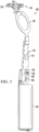
- FIGS. 1A and 1B top and bottom views (respectively) of one possible embodiment of the present disclosure is shown illustrating a shaving razor system 10.
- the shaving razor system 10 includes a shaving razor cartridge 12 mounted to a handle 14.
- the shaving razor cartridge 12 may be fixedly or pivotably mounted to the handle 14, depending on the overall desired cost and performance of the shaving razor system 10.
- the handle 14 holds a power source, such as one or more batteries (not shown) that supply power to a heating member 16 having a skin contacting surface 18.
- the heating member 16 may be a component of the handle 14 or the shaving razor cartridge 12.
- the heating element 16 may comprise a metal, such as aluminum or steel.
- the shaving razor cartridge 12 may be permanently attached or removably mounted from the handle 14, thus allowing the shaving razor cartridge 12 to be replaced.
- the shaving razor cartridge 12 may have a guard 20, a cap 22 and one or more blades 24 between the cap 22 and the guard 20.
- the blades 24 may be secured to the shaving razor cartridge with one or more clips 28a and 28b.
- the guard 20 may be toward a front portion of the shaving razor cartridge 12 and the cap 22 may be toward a rear portion of the shaving razor cartridge 12 (i.e., the guard 20 is in front of the blades 24 and the cap is behind the blades 24).
- the guard 20 and the cap 22 may define a shaving plane that is tangent to the guard 20 and the cap 22.
- the guard 20 may be a solid or segmented bar that extends generally parallel to the blades 24.
- the shaving razor cartridge 12 may comprise a skin-engaging member 26 (e.g., a plurality of fins or an elastomeric pad) in front of the blades 24 for stretching the skin during a shaving stroke.
- the skin-engaging member 26 may be insert injection molded or co-injection molded to the shaving razor cartridge 12.
- other known assembly methods may also be used such as adhesives, ultrasonic welding, or mechanical fasteners.
- the skin engaging member 26 may have a Shore A hardness of about 20, 30, or 40 to about 50, 60, or 70. A softer material may enhance skin stretching, as well as provide a more pleasant tactile feel against the skin of the user during shaving. A softer material may also aid in masking the less pleasant feel of the blades 24 or the guard 20 against the skin of the user during shaving.
- the heating element 16 may be positioned in front of the guard 20 and behind the skin engaging member 26.
- the heating element 16 may comprise a skin contacting surface 18 (e.g., a face plate) that delivers heat to a consumer's skin during a shaving stroke for an improved shaving experience.
- the heating element 16 may be mounted to either the shaving razor cartridge 12 or to a portion of the handle 14. It is understood that in other embodiments, the heating element may include heated blades or other skin contacting surfaces of the shaving razor cartridge or the handle 12.
- the heating element 16 may be controlled by an actuating member 34 (e.g., a button or a switch) in electrical communication with a power circuit (not shown) via a flexible circuit 36 ( FIG. 1A ).
- the handle 14 may include a light guide 32 having a transparent or translucent window 36 to indicate a status of the heating element 16.
- the actuating member 34 may act as a light guide to indicate the condition of the shaving razor system 10 (e.g., to indicate the power status or the heating level).
- the cap 22 may be a separate molded (e.g., a shaving aid filled reservoir) or extruded component (e.g., an extruded lubrication strip) that is mounted to the housing 18.
- the cap 22 may be a plastic or metal bar to aid in supporting the skin and define the shaving plane.
- the cap 22 may be molded or extruded from the same material as the housing 18 or may be molded or extruded from a more lubricious shaving aid composite that has one or more water-leachable shaving aid materials to provide increased comfort during shaving.
- the shaving aid composite may comprise a water-insoluble polymer and a skin-lubricating water-soluble polymer.
- Suitable water-insoluble polymers which may be used include, but are not limited to, polyethylene, polypropylene, polystyrene, butadiene-styrene copolymer (e.g., medium and high impact polystyrene), polyacetal, acrylonitrile-butadiene-styrene copolymer, ethylene vinyl acetate copolymer and blends such as polypropylene/polystyrene blend, may have a high impact polystyrene (i.e., Polystyrene-butadiene), such as Mobil 4324 (Mobil Corporation).
- polystyrene i.e., Polystyrene-butadiene
- Mobil 4324 Mobil Corporation
- the shaving razor system 10 may include a power source 40 (e.g., a rechargeable battery) positioned within the handle 14.
- the power source is in electrical contact with a circuit board 42 having a micro-controller 44.
- the actuating member 34 of FIG. 1B includes an electrical switch 46 that is in communication with the microcontroller 44 and the power source 40. For example, a consumer may contact the actuating member 34 which activates the electrical switch 46 positioned within the handle 14.
- the micro-controller 44 may set a first pre-determined temperature and a second pre-determined temperature for the heater element 16 of FIG. 1A .
- the second predetermined temperature is at least two, three, four or five degrees Celsius different from the first pre-determined temperature.
- the first predetermined temperature may be about 43 degrees Celsius, which may represent a high percentage of consumers that can feel a comfortable level of heat during a shaving stroke.
- the second predetermined temperature may be about 48 degrees Celsius, which may represent the highest temperature that most consumers can tolerate and do not feel an uncomfortable level of heat (e.g., burning sensation) during a shaving stroke.
- the predetermined temperatures are temperature settings, which may vary slightly from the actual temperature at the skin interface. For example, as the user strokes the shaving razor cartridge 12 against the skin, the temperature may drop due to limited electrical heating power of the system.
- the shaving razor system 10 having a heating element 16 ( FIG. 1A ) with a limited number of predetermined temperatures for heating the skin creates a more intuitive, safe and effective delivery of heat during a shaving stroke. It is believed, without being held to theory that much of the population can only tell a two degrees Celsius variance in temperature during shaving. A larger proportion of the population can tell a difference during a shaving stroke as the temperature difference increases to five degrees Celsius. Predetermined temperatures eliminate the guesswork for the consumer in choosing the proper temperature that will provide a comfortable level of heat without burning them.
- FIG. 3 a perspective view of a heating system 48 that may be incorporated into the shaving razor system 10 of FIG. 1A .
- the heating system 48 may include the power source 40, the circuit board 42, the electrical switch 46, a flexible electrical bridge 50 and the heating element 16.
- the heating element 16 may have at least one thermal sensor 52 and 54 for measuring the temperature of the heating element 16 and providing information to the microcontroller 44.
- the microcontroller 44 is in electrical communication with the heating element 16 and the electrical switch 46.
- the electrical switch 46 can toggle the heating element 16 between an on condition and an off condition.
- the heating element 16 In the off condition, no power may be supplied to the heating element. Accordingly, the heating element 16 may be at ambient temperature in the off condition (e.g., after the heating element 16 has cooled down).
- the heating element 16 In the on condition, the heating element 16 may be at the first pre-determined temperature or the second pre-determined condition. For example, when a consumer turns the heating element 16 to the off condition, the micro-controller 44 may store in memory if the heating element 16 was in the first pre-determined temperature or the second pre-determined temperature just prior to the off condition.
- the electrical switch 46 may toggle the heating element 16 between the first pre-determined condition and the second pre-determined condition.
- One or more LEDs 58, 59 and 60 may be positioned on the circuit board 42.
- the LEDs may be in electrical communication with the microcontroller 44 to indicate a condition of the heating element 16 and/or the status of power (e.g., an on or off condition).
- the electrical switch has a first toggle time for changing between the first pre-determined temperature and the second pre-determined temperature and a second toggle time for changing between the on condition and the off condition that are different.
- the first toggle time may greater than the second toggle time.
- the first toggle time may be at least two seconds and the second toggle time may be less than two seconds.
- a first LED 58 and a second LED 60 may be positioned on the circuit board 42.
- the microcontroller 44 FIG. 3
- the microcontroller 44 may electronically activate the first LED 58 for the first predetermined temperature and the second LED 60 for the second predetermined temperature.
- the first LED 58 may be a different color than the second LED 60, thus allowing the consumer to easily determine if the heating element 16 is set to the first pre-determined temperature or the second pre-determined temperature.
- the light guide 32 may have an arm 62 extending from a body 64.
- the arm 62 may have a bottom surface 65 that faces the first LED 58 and the second LED 60. Accordingly, light may travel from the first LED 58 and the second LED 60 through the arm 62 and to the body 64 of the light guide 32.
- the arm 62 may contact the electrical switch 46 to turn on and off power.
- a second arm 61 may extend from the body 64 to the actuating member 34.
- the actuating member 34 may have a bottom surface 63 that faces the third LED 59. Although only one LED 59 is shown positioned below the actuating member 34, it is understood there may be more than one LED having different colors, depending on the desired functionality and consumer feedback desired.
- FIG. 5 one possible embodiment of a block diagram of an electrical system 65 for controlling the energy of the shaving razor system 10 of FIG. 1A is illustrated.
- the power source 40 e.g., battery
- the electrical switch 46 (labeled as ON/OFF AND TEMPERATURE SWITCH) may send a signal to the micro-controller 44.
- the micro controller 44 may then output a signal to one of the first LED 58 (e.g., high temperature heating indicator, labeled as labeled as HEATING INDICATOR HIGH TEMP) or the second LED 60 (e.g., low temperature heating indicator, labeled as HEATING INDICATOR LOW TEMP) to indicate the desired temperature setting.
- the microcontroller 44 may also send an output signal to the power switching circuit 68, which sends a signal to the heating member 16 (labeled as HEATER) causing the heating member 16 to heat up to a specific predetermined temperature.
- One or more temperature sensors 70 measure the temperature from the heating member 16 and send a signal to the measurement and safety circuit 66 and the microcontroller 44.
- the measurement and safety circuit 66 sends a signal to the power switching circuit 68 in an event the temperature is above a certain threshold level (e.g., which may be uncomfortable or burn the skin).
- the power switching circuit 68 decreases or turns off power to the heating member 16 to bring down the temperature being measured by the temperature sensor(s) 70.
- the microcontroller 44 also receives a signal from the temperature sensor(s) 70. Accordingly, the microcontroller 44 may also decrease or turns off power to the heating member 16 to bring down the temperature being measured by the temperature sensor(s) 70. Accordingly, two independent systems are able to control the heating member 16 so it does not over heat, which may cause discomfort or burns to a consumer during shaving.
- the switch 46 may be pressed a second time to send another signal to the microcontroller 44 to change the temperature or to shut the power off.
- the microcontroller 44 determines what signal to send (e.g., an off signal to the power source 40 or a change in temperature signal to the power switching circuit 68) depending on how long the switch is pressed.
- the microcontroller 44 may send a signal to one of the LEDs 58, 60 to indicate the new set temperature and also a signal to the power switching circuit 68 to change the temperature of the heating member 16.
- the microcontroller 44 may send a signal to the power source 40 to shut power off to the power switching circuit 68, the measurement and safety circuit 66.
- the microcontroller 44 may also turn power off to both LEDs 58 and 60, thus indicating an off condition to the user.
- FIG. 6 another possible embodiment a block diagram of an electrical system 72 for controlling the energy of the shaving razor system 10 of FIG. 1A is illustrated.
- the electrical system 72 may have similar or the same components as the electrical system 65 of FIG. 5 .
- the electrical system 65 may substitute a temperature control and user interface circuit 74 for the microcontroller 44 of FIG. 5 .
- the switch 46 may be replaced by two separate switches 76 and 78.
- the on/off switch 76 may turn power either on or off upon actuation.
- Temperature of the heating member 16 may be changed by actuating the temperature selection switch 78.
- the switch 78 may have a first position for a first temperature setting and a second position for a second temperature setting.
- the power source 40 may supply power to the temperature control and user interface circuit 74, the measurement and safety circuit 66 and the power switching circuit 68.
- the switch 76 (labeled as SWITCH ON/OFF ) may send a signal to the temperature control and user interface circuit 74.
- the temperature control and user interface circuit 74 may then output a signal to one of the first LED 58 (e.g., high temperature heating indicator, labeled as labeled as HEATING INDICATOR HIGH TEMP) or the second LED 60 (e.g., low temperature heating indicator, labeled as HEATING INDICATOR LOW TEMP) depending on the position of the temperature selection switch 78, to indicate the desired temperature setting.
- the first LED 58 e.g., high temperature heating indicator, labeled as labeled as HEATING INDICATOR HIGH TEMP
- the second LED 60 e.g., low temperature heating indicator, labeled as HEATING INDICATOR LOW TEMP
- the temperature control and user interface circuit 74 may also send an output signal to the power switching circuit 68, which sends a signal to the heating member 16 (labeled as HEATER) causing the heating member 16 to heat up to a specific predetermined temperature.
- One or more temperature sensors 72 measure the temperature from the heating member 16 and send a signal to the measurement and safety circuit 66 and the microcontroller 44.
- the measurement and safety circuit 66 sends a signal to the power switching circuit 68 in an event the temperature is above a certain threshold level (e.g., which may be uncomfortable or burn the skin).
- the power switching circuit 68 decreases or turns off power to the heating member 16 to bring down the temperature being measured by the temperature sensor(s) 72.
- the temperature control and user interface circuit 74 also receives a signal from the temperature sensor(s) 72. Accordingly, the temperature control and user interface circuit 74 may also decrease or turns off power to the heating member 16 to bring down the temperature being measured by the temperature sensor(s) 72. Accordingly, two independent systems are able to control the heating member 16 so it does not over heat, which may cause discomfort or burns to a consumer during shaving.
- the switch 78 may be pressed or changed to send another signal to the temperature control and user interface circuit 74 to change the temperature to a second predetermined temperature.
- the temperature control and user interface circuit 74 may send a signal to one of the LEDs 58, 60 to indicate the new set temperature and also a signal to the power switching circuit 68 to change the temperature of the heating member 16.
- the temperature control and user interface circuit 74 may send a signal to the power source 40 to shut power off to the power switching circuit 68, the measurement and safety circuit 66 if the switch 76 is changed to an off position.
- the temperature control and user interface circuit 74 may also turn power off to both LEDs 58 and 60, thus indicating an off condition to the user.
Landscapes
- Life Sciences & Earth Sciences (AREA)
- Forests & Forestry (AREA)
- Engineering & Computer Science (AREA)
- Mechanical Engineering (AREA)
- Dry Shavers And Clippers (AREA)
Claims (12)
- Système de rasoir de rasage (10) comprenant :un manche (14) ;une cartouche de rasage (12) montée sur le manche ;une carte de circuit imprimé (42) ayant un commutateur électrique (46) en communication avec une source d'alimentation (40) positionnée à l'intérieur du manche ;un élément chauffant (16) en communication électrique avec le commutateur électrique (46), l'élément chauffant ayant une surface de contact avec la peau (18), dans lequel l'élément chauffant a une première température prédéterminée et une seconde température prédéterminée, et la seconde température prédéterminée est différente de la première température prédéterminée d'au moins deux degrés Celsius ;le système de rasoir de rasage comprenant un microcontrôleur (44) en communication électrique avec l'élément chauffant (16) et le commutateur électrique, caractérisé en ce que le commutateur électrique (46) a un premier temps de basculement pour changer entre la première température prédéterminée et la seconde température prédéterminée et un second temps de basculement pour changer entre une position de marche et une position d'arrêt, et au moins l'une de la première température prédéterminée et de la seconde température prédéterminée est réglée par le microcontrôleur (44).
- Système de rasoir de rasage (10) selon la revendication 1 dans lequel la seconde température prédéterminée est à au moins quatre degrés Celsius de la première température prédéterminée.
- Système de rasoir de rasage (10) selon l'une quelconque des revendications précédentes dans lequel la seconde température prédéterminée est une différence de quatre à cinq degrés Celsius de la première température prédéterminée.
- Système de rasoir de rasage (10) selon l'une quelconque des revendications précédentes dans lequel le commutateur électrique (46) bascule l'élément chauffant (16) entre un état de marche et un état d'arrêt.
- Système de rasoir de rasage (10) selon la revendication 4 dans lequel l'état de marche comprend l'élément chauffant (16) dans la première température prédéterminée ou l'élément chauffant dans la seconde température prédéterminée.
- Système de rasoir de rasage (10) selon l'une quelconque des revendications précédentes dans lequel le premier temps de basculement est supérieur au second temps de basculement.
- Système de rasoir de rasage (10) selon la revendication 6 dans lequel le premier temps de basculement est d'au moins 2 secondes.
- Système de rasoir de rasage (10) selon la revendication 7 dans lequel le second temps de basculement est inférieur à deux secondes.
- Système de rasoir de rasage (10) selon l'une quelconque des revendications précédentes comprenant en outre au moins un détecteur thermique (52, 54) en communication avec le microcontrôleur (44) pour mesurer la température de l'élément chauffant (16).
- Système de rasoir de rasage (10) selon l'une quelconque des revendications précédentes dans lequel la première température prédéterminée est de 43 degrés Celsius et la seconde température prédéterminée est de 48 degrés Celsius.
- Système de rasoir de rasage (10) selon l'une quelconque des revendications précédentes comprenant en outre une première DEL (58) et une seconde DEL (60) dans lequel le microcontrôleur (44) active la première DEL pour la première température prédéterminée et active la seconde DEL pour la seconde température prédéterminée.
- Système de rasoir de rasage (10) selon la revendication 11 dans lequel la première DEL (58) est d'une couleur différente d'une couleur de la seconde DEL (60).
Applications Claiming Priority (2)
| Application Number | Priority Date | Filing Date | Title |
|---|---|---|---|
| US201862650368P | 2018-03-30 | 2018-03-30 | |
| PCT/US2019/023063 WO2019190835A1 (fr) | 2018-03-30 | 2019-03-20 | Système de rasoir |
Publications (2)
| Publication Number | Publication Date |
|---|---|
| EP3774231A1 EP3774231A1 (fr) | 2021-02-17 |
| EP3774231B1 true EP3774231B1 (fr) | 2023-07-05 |
Family
ID=66041655
Family Applications (1)
| Application Number | Title | Priority Date | Filing Date |
|---|---|---|---|
| EP19715629.2A Active EP3774231B1 (fr) | 2018-03-30 | 2019-03-20 | Systeme de rasage |
Country Status (5)
| Country | Link |
|---|---|
| US (1) | US10894330B2 (fr) |
| EP (1) | EP3774231B1 (fr) |
| JP (1) | JP2021516101A (fr) |
| CN (1) | CN111819049B (fr) |
| WO (1) | WO2019190835A1 (fr) |
Families Citing this family (29)
| Publication number | Priority date | Publication date | Assignee | Title |
|---|---|---|---|---|
| US10652956B2 (en) | 2016-06-22 | 2020-05-12 | The Gillette Company Llc | Personal consumer product with thermal control circuitry and methods thereof |
| EP3351358B1 (fr) | 2017-01-20 | 2019-11-20 | The Gillette Company LLC | Élément chauffant pour un rasoir |
| USD952946S1 (en) | 2017-09-01 | 2022-05-24 | Church & Dwight Co., Inc. | Hair removal device |
| EP3552780B1 (fr) | 2018-03-30 | 2021-01-27 | The Gillette Company LLC | Cartouche de rasoir |
| CN111819049B (zh) * | 2018-03-30 | 2022-04-26 | 吉列有限责任公司 | 剃刮剃刀系统 |
| US11123888B2 (en) | 2018-03-30 | 2021-09-21 | The Gillette Company Llc | Razor handle with a pivoting portion |
| EP3774235A1 (fr) | 2018-03-30 | 2021-02-17 | The Gillette Company LLC | Manche de rasoir comprenant une partie rotative |
| EP3774230A1 (fr) | 2018-03-30 | 2021-02-17 | The Gillette Company LLC | Manche de rasoir comprenant une partie pivotante |
| US11607820B2 (en) | 2018-03-30 | 2023-03-21 | The Gillette Company Llc | Razor handle with movable members |
| CN111819044B (zh) | 2018-03-30 | 2022-09-16 | 吉列有限责任公司 | 具有枢转部分的剃刀柄部 |
| CN111819046B (zh) | 2018-03-30 | 2022-09-13 | 吉列有限责任公司 | 具有可移动构件的剃刀柄部 |
| CA3092881A1 (fr) | 2018-03-30 | 2019-10-03 | The Gillette Company Llc | Manche de rasoir avec elements mobiles |
| USD874061S1 (en) | 2018-03-30 | 2020-01-28 | The Gillette Company Llc | Shaving razor cartridge |
| CN111867795B (zh) | 2018-03-30 | 2022-03-18 | 吉列有限责任公司 | 剃刀柄部 |
| USD887641S1 (en) * | 2018-06-04 | 2020-06-16 | The Gillette Company Llc | Shaving razor button |
| USD937681S1 (en) | 2018-06-04 | 2021-12-07 | The Gillette Company Llc | Bottle for a shaving razor |
| USD942860S1 (en) | 2019-02-12 | 2022-02-08 | The Gillette Company Llc | Bottle for a shaving razor |
| EP3923765B1 (fr) | 2019-02-12 | 2023-04-05 | The Gillette Company LLC | Bouteille pour dispositif de soins personnels |
| EP3945933A1 (fr) * | 2019-04-05 | 2022-02-09 | The Gillette Company LLC | Dispositif de soin personnel de traitement de la peau et procédé de fabrication |
| USD914977S1 (en) | 2019-07-19 | 2021-03-30 | Church & Dwight Co., Inc. | Handle for hair removal apparatus |
| USD925830S1 (en) | 2019-07-19 | 2021-07-20 | Church & Dwight Co., Inc. | Head assembly for hair removal apparatus |
| EP3782778A1 (fr) * | 2019-08-20 | 2021-02-24 | Koninklijke Philips N.V. | Dispositif portatif de soins personnels avec un indicateur lumineux pour indiquer un état opérationnel |
| US11745370B2 (en) * | 2019-09-11 | 2023-09-05 | Dorco Co., Ltd. | Razor assembly for razor with induction heating system |
| USD936899S1 (en) | 2019-10-18 | 2021-11-23 | Church & Dwight Co., Inc. | Hair removal apparatus |
| USD914978S1 (en) | 2019-10-18 | 2021-03-30 | Church & Dwight Co., Inc. | Hair removal apparatus |
| USD940958S1 (en) | 2019-11-18 | 2022-01-11 | Church & Dwight Co., Inc. | Articulating blade assembly for hair removal device |
| USD942687S1 (en) | 2019-11-18 | 2022-02-01 | Church & Dwight Co., Inc. | Articulating blade assembly for hair removal device |
| US20220324127A1 (en) * | 2021-04-07 | 2022-10-13 | The Gillette Company Llc | Personal care appliance |
| US20220324126A1 (en) * | 2021-04-07 | 2022-10-13 | The Gillette Company Llc | Personal care appliance |
Family Cites Families (17)
| Publication number | Priority date | Publication date | Assignee | Title |
|---|---|---|---|---|
| US20060070242A1 (en) * | 2004-10-01 | 2006-04-06 | Szczepanowski Andrew A | Shaving razors and razor cartridges |
| US7367126B2 (en) * | 2005-09-06 | 2008-05-06 | The Gillette Company | Powered wet-shaving razor |
| US20070050995A1 (en) * | 2005-09-06 | 2007-03-08 | Fred Schnak | Razors |
| US20090255123A1 (en) * | 2008-04-15 | 2009-10-15 | Tomassetti Louis D | Razor with blade heating system |
| US20100031510A1 (en) * | 2008-08-06 | 2010-02-11 | Matthias Gester | Heated shaving razor |
| PL2218559T3 (pl) * | 2009-02-13 | 2013-01-31 | Edgewell Personal Care Brands Llc | Urządzenie do pielęgnacji ciała |
| US8209868B2 (en) * | 2009-07-27 | 2012-07-03 | The Gillette Company | Device with an illuminated button assembly |
| US20120227554A1 (en) * | 2011-03-07 | 2012-09-13 | Jack Beech | Grooming device with leveling indicators |
| US20120279075A1 (en) * | 2011-05-02 | 2012-11-08 | Amsel Klaus Guenter | Improved battery housing for battery-powered device |
| US9084891B2 (en) * | 2012-02-06 | 2015-07-21 | David Aberizk | Pilomotor effect stimulating device and method |
| JP6098117B2 (ja) * | 2012-10-31 | 2017-03-22 | 日立工機株式会社 | 携帯用工具 |
| CN203031634U (zh) * | 2013-01-11 | 2013-07-03 | 吴海翔 | 充电宝剃须刀 |
| US9440366B2 (en) * | 2013-11-15 | 2016-09-13 | Heated Blades Holding Company, Llc | System for regulating electric current flow from a power source to a blade cartridge in a wet shave razor |
| US9751228B2 (en) * | 2014-01-14 | 2017-09-05 | The Gillette Company Llc | Shaving cartridges having thermal sensors |
| US9908250B2 (en) * | 2014-01-14 | 2018-03-06 | The Gillette Company Llc | Heated shaving razors |
| JP6298574B2 (ja) | 2014-07-07 | 2018-03-20 | コーニンクレッカ フィリップス エヌ ヴェKoninklijke Philips N.V. | ヘアクリッピングデバイス |
| CN111819049B (zh) * | 2018-03-30 | 2022-04-26 | 吉列有限责任公司 | 剃刮剃刀系统 |
-
2019
- 2019-03-20 CN CN201980015177.XA patent/CN111819049B/zh active Active
- 2019-03-20 WO PCT/US2019/023063 patent/WO2019190835A1/fr active Application Filing
- 2019-03-20 JP JP2020546150A patent/JP2021516101A/ja active Pending
- 2019-03-20 EP EP19715629.2A patent/EP3774231B1/fr active Active
- 2019-03-28 US US16/367,318 patent/US10894330B2/en active Active
Also Published As
| Publication number | Publication date |
|---|---|
| US20190299466A1 (en) | 2019-10-03 |
| WO2019190835A1 (fr) | 2019-10-03 |
| JP2021516101A (ja) | 2021-07-01 |
| EP3774231A1 (fr) | 2021-02-17 |
| CN111819049A (zh) | 2020-10-23 |
| CN111819049B (zh) | 2022-04-26 |
| US10894330B2 (en) | 2021-01-19 |
Similar Documents
| Publication | Publication Date | Title |
|---|---|---|
| EP3774231B1 (fr) | Systeme de rasage | |
| AU2017232212B2 (en) | Heated shaving razors | |
| US20190299465A1 (en) | Heated shaving razor | |
| EP3094456B1 (fr) | Cartouches de rasage présentant des capteurs thermiques |
Legal Events
| Date | Code | Title | Description |
|---|---|---|---|
| STAA | Information on the status of an ep patent application or granted ep patent |
Free format text: STATUS: UNKNOWN |
|
| STAA | Information on the status of an ep patent application or granted ep patent |
Free format text: STATUS: THE INTERNATIONAL PUBLICATION HAS BEEN MADE |
|
| PUAI | Public reference made under article 153(3) epc to a published international application that has entered the european phase |
Free format text: ORIGINAL CODE: 0009012 |
|
| STAA | Information on the status of an ep patent application or granted ep patent |
Free format text: STATUS: REQUEST FOR EXAMINATION WAS MADE |
|
| 17P | Request for examination filed |
Effective date: 20200921 |
|
| AK | Designated contracting states |
Kind code of ref document: A1 Designated state(s): AL AT BE BG CH CY CZ DE DK EE ES FI FR GB GR HR HU IE IS IT LI LT LU LV MC MK MT NL NO PL PT RO RS SE SI SK SM TR |
|
| AX | Request for extension of the european patent |
Extension state: BA ME |
|
| DAV | Request for validation of the european patent (deleted) | ||
| DAX | Request for extension of the european patent (deleted) | ||
| STAA | Information on the status of an ep patent application or granted ep patent |
Free format text: STATUS: EXAMINATION IS IN PROGRESS |
|
| 17Q | First examination report despatched |
Effective date: 20211012 |
|
| GRAP | Despatch of communication of intention to grant a patent |
Free format text: ORIGINAL CODE: EPIDOSNIGR1 |
|
| STAA | Information on the status of an ep patent application or granted ep patent |
Free format text: STATUS: GRANT OF PATENT IS INTENDED |
|
| INTG | Intention to grant announced |
Effective date: 20230221 |
|
| GRAS | Grant fee paid |
Free format text: ORIGINAL CODE: EPIDOSNIGR3 |
|
| GRAA | (expected) grant |
Free format text: ORIGINAL CODE: 0009210 |
|
| STAA | Information on the status of an ep patent application or granted ep patent |
Free format text: STATUS: THE PATENT HAS BEEN GRANTED |
|
| P01 | Opt-out of the competence of the unified patent court (upc) registered |
Effective date: 20230430 |
|
| AK | Designated contracting states |
Kind code of ref document: B1 Designated state(s): AL AT BE BG CH CY CZ DE DK EE ES FI FR GB GR HR HU IE IS IT LI LT LU LV MC MK MT NL NO PL PT RO RS SE SI SK SM TR |
|
| REG | Reference to a national code |
Ref country code: CH Ref legal event code: EP |
|
| REG | Reference to a national code |
Ref country code: AT Ref legal event code: REF Ref document number: 1584417 Country of ref document: AT Kind code of ref document: T Effective date: 20230715 |
|
| REG | Reference to a national code |
Ref country code: DE Ref legal event code: R096 Ref document number: 602019032108 Country of ref document: DE |
|
| REG | Reference to a national code |
Ref country code: IE Ref legal event code: FG4D |
|
| REG | Reference to a national code |
Ref country code: LT Ref legal event code: MG9D |
|
| REG | Reference to a national code |
Ref country code: NL Ref legal event code: MP Effective date: 20230705 |
|
| REG | Reference to a national code |
Ref country code: AT Ref legal event code: MK05 Ref document number: 1584417 Country of ref document: AT Kind code of ref document: T Effective date: 20230705 |
|
| PG25 | Lapsed in a contracting state [announced via postgrant information from national office to epo] |
Ref country code: NL Free format text: LAPSE BECAUSE OF FAILURE TO SUBMIT A TRANSLATION OF THE DESCRIPTION OR TO PAY THE FEE WITHIN THE PRESCRIBED TIME-LIMIT Effective date: 20230705 |
|
| PG25 | Lapsed in a contracting state [announced via postgrant information from national office to epo] |
Ref country code: GR Free format text: LAPSE BECAUSE OF FAILURE TO SUBMIT A TRANSLATION OF THE DESCRIPTION OR TO PAY THE FEE WITHIN THE PRESCRIBED TIME-LIMIT Effective date: 20231006 |
|
| PG25 | Lapsed in a contracting state [announced via postgrant information from national office to epo] |
Ref country code: ES Free format text: LAPSE BECAUSE OF FAILURE TO SUBMIT A TRANSLATION OF THE DESCRIPTION OR TO PAY THE FEE WITHIN THE PRESCRIBED TIME-LIMIT Effective date: 20230705 |
|
| PG25 | Lapsed in a contracting state [announced via postgrant information from national office to epo] |
Ref country code: IS Free format text: LAPSE BECAUSE OF FAILURE TO SUBMIT A TRANSLATION OF THE DESCRIPTION OR TO PAY THE FEE WITHIN THE PRESCRIBED TIME-LIMIT Effective date: 20231105 |
|
| PG25 | Lapsed in a contracting state [announced via postgrant information from national office to epo] |
Ref country code: SE Free format text: LAPSE BECAUSE OF FAILURE TO SUBMIT A TRANSLATION OF THE DESCRIPTION OR TO PAY THE FEE WITHIN THE PRESCRIBED TIME-LIMIT Effective date: 20230705 Ref country code: RS Free format text: LAPSE BECAUSE OF FAILURE TO SUBMIT A TRANSLATION OF THE DESCRIPTION OR TO PAY THE FEE WITHIN THE PRESCRIBED TIME-LIMIT Effective date: 20230705 Ref country code: PT Free format text: LAPSE BECAUSE OF FAILURE TO SUBMIT A TRANSLATION OF THE DESCRIPTION OR TO PAY THE FEE WITHIN THE PRESCRIBED TIME-LIMIT Effective date: 20231106 Ref country code: NO Free format text: LAPSE BECAUSE OF FAILURE TO SUBMIT A TRANSLATION OF THE DESCRIPTION OR TO PAY THE FEE WITHIN THE PRESCRIBED TIME-LIMIT Effective date: 20231005 Ref country code: LV Free format text: LAPSE BECAUSE OF FAILURE TO SUBMIT A TRANSLATION OF THE DESCRIPTION OR TO PAY THE FEE WITHIN THE PRESCRIBED TIME-LIMIT Effective date: 20230705 Ref country code: LT Free format text: LAPSE BECAUSE OF FAILURE TO SUBMIT A TRANSLATION OF THE DESCRIPTION OR TO PAY THE FEE WITHIN THE PRESCRIBED TIME-LIMIT Effective date: 20230705 Ref country code: IS Free format text: LAPSE BECAUSE OF FAILURE TO SUBMIT A TRANSLATION OF THE DESCRIPTION OR TO PAY THE FEE WITHIN THE PRESCRIBED TIME-LIMIT Effective date: 20231105 Ref country code: HR Free format text: LAPSE BECAUSE OF FAILURE TO SUBMIT A TRANSLATION OF THE DESCRIPTION OR TO PAY THE FEE WITHIN THE PRESCRIBED TIME-LIMIT Effective date: 20230705 Ref country code: GR Free format text: LAPSE BECAUSE OF FAILURE TO SUBMIT A TRANSLATION OF THE DESCRIPTION OR TO PAY THE FEE WITHIN THE PRESCRIBED TIME-LIMIT Effective date: 20231006 Ref country code: FI Free format text: LAPSE BECAUSE OF FAILURE TO SUBMIT A TRANSLATION OF THE DESCRIPTION OR TO PAY THE FEE WITHIN THE PRESCRIBED TIME-LIMIT Effective date: 20230705 Ref country code: ES Free format text: LAPSE BECAUSE OF FAILURE TO SUBMIT A TRANSLATION OF THE DESCRIPTION OR TO PAY THE FEE WITHIN THE PRESCRIBED TIME-LIMIT Effective date: 20230705 Ref country code: AT Free format text: LAPSE BECAUSE OF FAILURE TO SUBMIT A TRANSLATION OF THE DESCRIPTION OR TO PAY THE FEE WITHIN THE PRESCRIBED TIME-LIMIT Effective date: 20230705 |
|
| PG25 | Lapsed in a contracting state [announced via postgrant information from national office to epo] |
Ref country code: PL Free format text: LAPSE BECAUSE OF FAILURE TO SUBMIT A TRANSLATION OF THE DESCRIPTION OR TO PAY THE FEE WITHIN THE PRESCRIBED TIME-LIMIT Effective date: 20230705 |
|
| REG | Reference to a national code |
Ref country code: DE Ref legal event code: R097 Ref document number: 602019032108 Country of ref document: DE |
|
| PG25 | Lapsed in a contracting state [announced via postgrant information from national office to epo] |
Ref country code: SM Free format text: LAPSE BECAUSE OF FAILURE TO SUBMIT A TRANSLATION OF THE DESCRIPTION OR TO PAY THE FEE WITHIN THE PRESCRIBED TIME-LIMIT Effective date: 20230705 Ref country code: RO Free format text: LAPSE BECAUSE OF FAILURE TO SUBMIT A TRANSLATION OF THE DESCRIPTION OR TO PAY THE FEE WITHIN THE PRESCRIBED TIME-LIMIT Effective date: 20230705 Ref country code: EE Free format text: LAPSE BECAUSE OF FAILURE TO SUBMIT A TRANSLATION OF THE DESCRIPTION OR TO PAY THE FEE WITHIN THE PRESCRIBED TIME-LIMIT Effective date: 20230705 Ref country code: DK Free format text: LAPSE BECAUSE OF FAILURE TO SUBMIT A TRANSLATION OF THE DESCRIPTION OR TO PAY THE FEE WITHIN THE PRESCRIBED TIME-LIMIT Effective date: 20230705 Ref country code: CZ Free format text: LAPSE BECAUSE OF FAILURE TO SUBMIT A TRANSLATION OF THE DESCRIPTION OR TO PAY THE FEE WITHIN THE PRESCRIBED TIME-LIMIT Effective date: 20230705 Ref country code: SK Free format text: LAPSE BECAUSE OF FAILURE TO SUBMIT A TRANSLATION OF THE DESCRIPTION OR TO PAY THE FEE WITHIN THE PRESCRIBED TIME-LIMIT Effective date: 20230705 |
|
| PGFP | Annual fee paid to national office [announced via postgrant information from national office to epo] |
Ref country code: DE Payment date: 20240130 Year of fee payment: 6 |
|
| PLBE | No opposition filed within time limit |
Free format text: ORIGINAL CODE: 0009261 |
|
| STAA | Information on the status of an ep patent application or granted ep patent |
Free format text: STATUS: NO OPPOSITION FILED WITHIN TIME LIMIT |