EP3774144B1 - Schneidwerkzeug und schneideinsatz mit komplementären eingriffsmerkmalen zur exzentrischen lagerung - Google Patents
Schneidwerkzeug und schneideinsatz mit komplementären eingriffsmerkmalen zur exzentrischen lagerung Download PDFInfo
- Publication number
- EP3774144B1 EP3774144B1 EP19713879.5A EP19713879A EP3774144B1 EP 3774144 B1 EP3774144 B1 EP 3774144B1 EP 19713879 A EP19713879 A EP 19713879A EP 3774144 B1 EP3774144 B1 EP 3774144B1
- Authority
- EP
- European Patent Office
- Prior art keywords
- insert
- cutting
- contact
- cutting insert
- cutting tool
- Prior art date
- Legal status (The legal status is an assumption and is not a legal conclusion. Google has not performed a legal analysis and makes no representation as to the accuracy of the status listed.)
- Active
Links
Images


Classifications
-
- B—PERFORMING OPERATIONS; TRANSPORTING
- B23—MACHINE TOOLS; METAL-WORKING NOT OTHERWISE PROVIDED FOR
- B23C—MILLING
- B23C5/00—Milling-cutters
- B23C5/16—Milling-cutters characterised by physical features other than shape
- B23C5/20—Milling-cutters characterised by physical features other than shape with removable cutter bits or teeth or cutting inserts
- B23C5/22—Securing arrangements for bits or teeth or cutting inserts
- B23C5/2204—Securing arrangements for bits or teeth or cutting inserts with cutting inserts clamped against the walls of the recess in the cutter body by a clamping member acting upon the wall of a hole in the insert
- B23C5/2208—Securing arrangements for bits or teeth or cutting inserts with cutting inserts clamped against the walls of the recess in the cutter body by a clamping member acting upon the wall of a hole in the insert for plate-like cutting inserts
- B23C5/2213—Securing arrangements for bits or teeth or cutting inserts with cutting inserts clamped against the walls of the recess in the cutter body by a clamping member acting upon the wall of a hole in the insert for plate-like cutting inserts having a special shape
-
- B—PERFORMING OPERATIONS; TRANSPORTING
- B23—MACHINE TOOLS; METAL-WORKING NOT OTHERWISE PROVIDED FOR
- B23C—MILLING
- B23C5/00—Milling-cutters
- B23C5/02—Milling-cutters characterised by the shape of the cutter
- B23C5/06—Face-milling cutters, i.e. having only or primarily a substantially flat cutting surface
-
- B—PERFORMING OPERATIONS; TRANSPORTING
- B23—MACHINE TOOLS; METAL-WORKING NOT OTHERWISE PROVIDED FOR
- B23C—MILLING
- B23C5/00—Milling-cutters
- B23C5/02—Milling-cutters characterised by the shape of the cutter
- B23C5/08—Disc-type cutters
-
- B—PERFORMING OPERATIONS; TRANSPORTING
- B23—MACHINE TOOLS; METAL-WORKING NOT OTHERWISE PROVIDED FOR
- B23C—MILLING
- B23C2200/00—Details of milling cutting inserts
- B23C2200/04—Overall shape
- B23C2200/0455—Square
- B23C2200/0461—Square rounded
-
- B—PERFORMING OPERATIONS; TRANSPORTING
- B23—MACHINE TOOLS; METAL-WORKING NOT OTHERWISE PROVIDED FOR
- B23C—MILLING
- B23C2200/00—Details of milling cutting inserts
- B23C2200/08—Rake or top surfaces
-
- B—PERFORMING OPERATIONS; TRANSPORTING
- B23—MACHINE TOOLS; METAL-WORKING NOT OTHERWISE PROVIDED FOR
- B23C—MILLING
- B23C2200/00—Details of milling cutting inserts
- B23C2200/08—Rake or top surfaces
- B23C2200/081—Rake or top surfaces with projections
-
- B—PERFORMING OPERATIONS; TRANSPORTING
- B23—MACHINE TOOLS; METAL-WORKING NOT OTHERWISE PROVIDED FOR
- B23C—MILLING
- B23C2200/00—Details of milling cutting inserts
- B23C2200/08—Rake or top surfaces
- B23C2200/085—Rake or top surfaces discontinuous
-
- B—PERFORMING OPERATIONS; TRANSPORTING
- B23—MACHINE TOOLS; METAL-WORKING NOT OTHERWISE PROVIDED FOR
- B23C—MILLING
- B23C2200/00—Details of milling cutting inserts
- B23C2200/08—Rake or top surfaces
- B23C2200/086—Rake or top surfaces with one or more grooves
-
- B—PERFORMING OPERATIONS; TRANSPORTING
- B23—MACHINE TOOLS; METAL-WORKING NOT OTHERWISE PROVIDED FOR
- B23C—MILLING
- B23C2200/00—Details of milling cutting inserts
- B23C2200/16—Supporting or bottom surfaces
-
- B—PERFORMING OPERATIONS; TRANSPORTING
- B23—MACHINE TOOLS; METAL-WORKING NOT OTHERWISE PROVIDED FOR
- B23C—MILLING
- B23C2200/00—Details of milling cutting inserts
- B23C2200/16—Supporting or bottom surfaces
- B23C2200/161—Supporting or bottom surfaces with projections
-
- B—PERFORMING OPERATIONS; TRANSPORTING
- B23—MACHINE TOOLS; METAL-WORKING NOT OTHERWISE PROVIDED FOR
- B23C—MILLING
- B23C2200/00—Details of milling cutting inserts
- B23C2200/16—Supporting or bottom surfaces
- B23C2200/164—Supporting or bottom surfaces discontinuous
-
- B—PERFORMING OPERATIONS; TRANSPORTING
- B23—MACHINE TOOLS; METAL-WORKING NOT OTHERWISE PROVIDED FOR
- B23C—MILLING
- B23C2200/00—Details of milling cutting inserts
- B23C2200/16—Supporting or bottom surfaces
- B23C2200/165—Supporting or bottom surfaces with one or more grooves
-
- B—PERFORMING OPERATIONS; TRANSPORTING
- B23—MACHINE TOOLS; METAL-WORKING NOT OTHERWISE PROVIDED FOR
- B23C—MILLING
- B23C2200/00—Details of milling cutting inserts
- B23C2200/16—Supporting or bottom surfaces
- B23C2200/168—Supporting or bottom surfaces with features related to indexing
-
- B—PERFORMING OPERATIONS; TRANSPORTING
- B23—MACHINE TOOLS; METAL-WORKING NOT OTHERWISE PROVIDED FOR
- B23C—MILLING
- B23C2200/00—Details of milling cutting inserts
- B23C2200/28—Angles
- B23C2200/287—Positive rake angles
-
- B—PERFORMING OPERATIONS; TRANSPORTING
- B23—MACHINE TOOLS; METAL-WORKING NOT OTHERWISE PROVIDED FOR
- B23C—MILLING
- B23C2210/00—Details of milling cutters
- B23C2210/16—Fixation of inserts or cutting bits in the tool
- B23C2210/163—Indexing
-
- B—PERFORMING OPERATIONS; TRANSPORTING
- B23—MACHINE TOOLS; METAL-WORKING NOT OTHERWISE PROVIDED FOR
- B23C—MILLING
- B23C2210/00—Details of milling cutters
- B23C2210/16—Fixation of inserts or cutting bits in the tool
- B23C2210/165—Fixation bolts
-
- B—PERFORMING OPERATIONS; TRANSPORTING
- B23—MACHINE TOOLS; METAL-WORKING NOT OTHERWISE PROVIDED FOR
- B23C—MILLING
- B23C2210/00—Details of milling cutters
- B23C2210/16—Fixation of inserts or cutting bits in the tool
- B23C2210/168—Seats for cutting inserts, supports for replacable cutting bits
-
- B—PERFORMING OPERATIONS; TRANSPORTING
- B23—MACHINE TOOLS; METAL-WORKING NOT OTHERWISE PROVIDED FOR
- B23C—MILLING
- B23C2210/00—Details of milling cutters
- B23C2210/20—Number of cutting edges
- B23C2210/208—Number of cutting edges ten
-
- B—PERFORMING OPERATIONS; TRANSPORTING
- B23—MACHINE TOOLS; METAL-WORKING NOT OTHERWISE PROVIDED FOR
- B23C—MILLING
- B23C2265/00—Details of general geometric configurations
- B23C2265/12—Eccentric
Definitions
- the present invention relates to a cutting tool according to the preamble of claim 1 and a square, double-sided cutting insert according to the preamble of claim 15.
- An example of such a cutting tool and cutting insert is known from US 8,905,683 .
- Further examples of related cutting tools and inserts are found in e.g. EP 1 952 925 A2 , EP 2 614 907 A1 and EP 2 617 505 A1 .
- US 7,090,443 discloses a slotting tool comprising an insert holder in the form of a circular disc with a plurality of non-indexable cutting inserts removably retained in identical insert pockets arranged around the periphery of the disc.
- Each cutting insert has a through bore with a retaining screw passing therethrough and engaging a threaded bore in the associated insert pocket.
- Lateral stability of each cutting insert relative to the insert holder is provided by the lower and rear surfaces of the cutting insert having generally V-shape concave (or convex) cross sections, which mate corresponding generally V-shape convex (or concave) cross sections of the lower and rear abutment surfaces of the associated insert pocket.
- US 8,905,683 discloses a rotary cutting tool comprising a tool body having a plurality of seating surfaces adjacent a forward facing end surface, and an equal number of indexable cutting inserts removably secured therein.
- Each cutting insert is oriented on its respective seating surface such that only a single abutment portion of one its four flank surfaces is in abutting contact with a radially outward facing support surface on the tool body, and there are no other points or regions of abutting contact between the insert's peripheral side surface and the cutting body.
- Each cutting insert has a non-circular clamping bore and a rigid clamping screw passing therethrough which engages a threaded bore in the associated seating surface. A non-threaded portion of the clamping screw simultaneously applies four clamping forces at four operative clamping portions of the non-circular clamping bore to provide axial support for the cutting insert.
- a square, double-sided cutting insert indexable about a first axis according to claim 15.
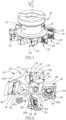
- the present invention relates to a cutting tool 20 comprising a tool body 22 having a first insert receiving pocket 24 and an indexable cutting insert 26 removably mounted therein.
- the cutting insert 26 may preferably be manufactured by form pressing and sintering a cemented carbide, such as tungsten carbide, and may be coated or uncoated.
- the first insert receiving pocket 24 comprises a first seat surface 28 and a first support wall 30 transverse thereto, the first seat surface 28 having a plurality of male or female first engagement elements 32a, 32b.
- each first engagement element 32a, 32b may be partially spherical.
- the first seat surface 28 and the first support wall 30 may be spaced apart by a stress relief groove 34.
- the first seat surface 28 may be formed on a shim removably retained in the first insert receiving pocket 24.
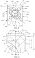
- the cutting insert 26 comprises opposing upper and lower surfaces 36, 38 and a continuous boundary surface 40 extending therebetween, and the cutting insert 26 is indexable about a first axis A1 passing through the upper and lower surfaces 36, 38.
- the boundary surface 40 may intersect the upper and lower surfaces 36, 38 to form continuous upper and lower boundary edges 42, 44, respectively.
- an insert bore 46 may intersect the upper and lower surfaces 36, 38.
- the insert bore 46 may have a second axis A2 coaxial with the first axis A1.
- the boundary surface 40 has a plurality of N1 first peripheral surfaces 48a, 48b circumferentially alternating with a plurality of N1 second peripheral surfaces 50a, 50b, each first peripheral surface 48a, 48b intersecting the upper surface 36 to form a first upper cutting edge 52a, 52b, and each second peripheral surface 50a, 50b intersecting the upper surface 36 to form a second upper cutting edge 54a, 54b.
- first and second upper cutting edges 52a, 52b; 54a, 54b are distinct portions of the upper boundary edge 42.
- N1 is a whole number greater than one, i.e. N1 > 1.
- N1 may be exactly 2.
- the plurality of first and second upper cutting edges 52a, 52b; 54a, 54b may be straight.
- first and second peripheral surfaces 48a, 48b; 50a, 50b may be described as flank surfaces.
- a median plane M perpendicular to the first axis A1 intersects the boundary surface 40.
- the insert bore 46 may pass through the median plane M, and the median plane M may pass midway between the upper and lower surfaces 36, 38.
- the cutting insert 26 in a cross-section taken in the median plane M, may exhibit N1 *2-fold symmetry about the first axis A1.
- the plurality of first peripheral surfaces 48a, 48b and the plurality of second peripheral surfaces 50a, 50b may define an imaginary square S.
- the insert bore 46 may be circular.
- the cutting insert 26 may be configured in a compact size.
- the boundary surface 40 may also include a plurality of N1 third peripheral surfaces 56a, 56b circumferentially alternating with a plurality of N1 fourth peripheral surfaces 58a, 58b, each third peripheral surface 56a, 56b intersecting the upper surface 36 to form a third upper edge 60a, 60b, and each fourth peripheral surface 58a, 58b intersecting the upper surface 36 to form a fourth upper edge 62a, 62b.
- the third and fourth upper edges 60a, 60b; 62a, 62b may be curved.
- each third upper edge 60a, 60b may extend between one of the first upper cutting edges 52a, 52b and one of the second upper cutting edges 54a, 54b
- each fourth upper edge 62a, 62b may extend between one of the first upper cutting edges 52a, 52b and one of the second upper cutting edges 54a, 54b.
- each curved third and fourth upper edge 60a, 60b; 62a, 62b may subtend a corner angle ⁇ 1 of 90 degrees.
- the plurality of third and fourth peripheral surfaces 56a, 56b; 58a, 58b may be described as corner surfaces, and the plurality of third and fourth upper edges 60a, 60b; 62a, 62b may be described as corner edges.
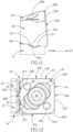
- the plurality of fourth upper edges 62a, 62b may be located closer to the median plane M than the plurality of third upper edges 60a, 60b.
- the plurality of third upper edges 60a, 60b may be described as diametrically opposite raised corner edges, and the plurality of fourth upper edges 62a, 62b may be described as diametrically opposite lowered corner edges. It is understood that “raised” and “lowered” are defined relative to the median plane M with the raised corner edges being farther from the median plane M than the lowered corner edges.
- the lower surface 38 may also have a pair diametrically opposite lowered corner edges 96a, 96b formed at the intersection of lower surface 38 with the first diametrically opposite pair of corner surfaces 56a, 56b and a pair of diametrically opposite raised corner edges 98a, 98b formed at the intersection of the lower surface 38 with the second diametrically opposite pair of corner surfaces 58a, 58b.
- the plurality of third upper edges 60a, 60b may be cutting edges.
- a first plane P1 containing first axis A1 may intersect the plurality of third upper edges 60a, 60b .
- the lower surface 38 has a plurality of discrete, spaced apart female or male lower engaging elements 64a, 64b.
- the female or male lower engaging elements 64a, 64b may be formed on inclined portions of the lower surface 38, the portions being inclined relative to the median plane M. Additionally, the lower engaging elements 64a, 64b may be spaced apart from both the insert bore 46 and the boundary surface 40 .
- the lower surface 38 may have a plurality of N1*N2 lower engaging elements 64a, 64b.
- N2 is a whole number equal to or greater than one, i.e. N2 ⁇ 1.
- N2 may be exactly 1.
- the first plane P1 may intersect none of the plurality of lower engaging elements 64a, 64b.
- the lower surface 38 may exhibit N1*N3- fold rotational symmetry about the first axis A1.
- N3 is a whole number equal to or greater than one, i.e. N3 ⁇ 1.
- N3 may be exactly 1.
- a second plane P2 containing first axis A1 and perpendicular to the first plane P1 may intersect at least two of the plurality of lower engaging elements 64a, 64b.
- the plurality of first engagement elements 32a, 32b may be equal in number to the plurality of lower engaging elements 64a, 64b.
- each lower engaging element 64a, 64b may not intersect the boundary surface 40.
- each lower engaging element 64a, 64b may be entirely spaced apart from the lower boundary edge 44.
- each lower engaging element 64a, 64b may be partially spherical.
- the cutting insert 26 has N1 index positions with the lower surface 38 in contact with the first seat surface 28.
- the plurality of first engagement elements 32a, 32b do not simultaneously prevent translation of the cutting insert 26 in a third direction D3 opposite to the second direction D2.
- a clamping member 66 in each index position with the lower surface 38 in contact with the first seat surface 28, may contact the insert bore 46 and prevent translation of the cutting insert 26 in the third direction D3.
- the clamping member 66 may be a clamping screw extending through the insert bore 46 and threadingly engaging a first seat bore 68 in the first seat surface 28.
- the first seat bore 68 may have a third axis A3 non-coaxial with the second axis A2.
- the clamping member 66 may be a standard clamping screw.
- the cutting insert 26 may be removably mounted to the tool body 22 in a simple and cost-effective manner.
- each female first engagement element 32a, 32b or female lower engaging element 64a, 64b has a first length L1 in the second direction D2
- each male lower engaging element 64a, 64b or male first engagement element 32a, 32b has a second length L2 in the second direction D2.
- the first length L1 may be greater than the second length L2.
- each first engagement element 32a, 32b may be a female recessed element
- each lower engaging element 64a, 64b may be a male protruding element
- the first seat surface 28 may be simply and cost-effectively manufactured.
- the first seat surface 28 may have two spaced apart planar first bearing surfaces 70a, 70b.
- the two first bearing surfaces 70a, 70b may be mutually inclined. More particularly, the two first bearing surfaces 70a, 70b may lie on planes which meet above the first seat surface 28.
- the lower surface 38 in each index position with the lower surface 38 in contact with the first seat surface 28, the lower surface 38 may contact the two first bearing surfaces 70a, 70b.
- each of the plurality of first engagement elements 32a, 32b may be at least partially located on one or the other of the two first bearing surfaces 70a, 70b.
- a first lower contact zone ZL1 of each lower engaging element 64a, 64b is in contact with one of the first engagement elements 32a, 32b.
- each lower engaging element 64a, 64b is in contact with another one of the first engagement elements 32a, 32b.
- first and second lower contact zones ZL1, ZL2 of each lower engaging element 64a, 64b may be different from each other.
- first and second lower contact zones ZL1, ZL2 of each lower engaging element 64a, 64b may be non-overlapping and thus spaced apart from each other.
- first and second lower contact zones ZL1, ZL2 of each lower engaging element 64a, 64b may be non-planar.
- each lower engaging element 64a, 64b has a lower bisector BL, and the first and second lower contact zones ZL1, ZL2 of each lower engaging element 64a, 64b may be entirely located on opposite sides of their respective lower bisector BL.
- each lower bisector BL may be parallel to the first direction D1 in both the first and second index positions.
- a planar first peripheral contact zone ZP1 of one of the boundary surface's first peripheral surfaces 48a, 48b may be in contact with the first support wall 30.
- the first peripheral contact zone ZP1 may be parallel to the first axis A1 .
- the first support wall 30 may have two spaced apart support regions, and thus the first peripheral contact zone ZP1 may comprise two spaced apart sub-zones.
- the entire boundary surface 40 may extend parallel to the first axis A1 .
- the cutting tool 20 may be rotatable about a tool axis AT in a direction of rotation R, and the cutting body 22 may have a holder portion 72 in which the cutting insert 26 is removably mounted in the first insert receiving pocket 24, the holder portion 72 having an axially forward facing front end 74.
- a shank portion 75 may extend rearwardly from the holder portion 72 along the tool axis AT.
- the first direction D1 may be radially inward, and the second direction D2 may be axially rearward.
- the third direction D3 may be axially forward, and the first support wall 30 may be described as a radially outward facing first support wall.
- a third plane P3 perpendicular to tool axis AT may intersect the first support wall 30 and an operative first upper cutting edge 52a', 52b' of the cutting insert 26 at a first mid-point M1 thereof, and an operative second upper cutting edge 54a', 54b' of the cutting insert 26 may be located axially forward of the third plane P3.
- the operative first upper cutting edge 52a', 52b' of the associated cutting insert 26 may have a positive first axial rake angle ⁇ 1 .
- an operative third upper edge 60a', 60b' extending between the operative first and second upper cutting edges 52a', 52b'; 54a', 54b' may be located axially forward of the third plane P3.
- the holder portion 72 may have a plurality of circumferentially spaced apart first insert receiving pockets 24, each having a cutting insert 26 removably mounted therein.
- the cutting tool 20 may be a slot milling tool.
- the present invention is advantageous in that axial support for each cutting insert 26 in its associated first insert receiving pocket 24 is provided by the plurality of first engagement elements 32a, 32b on the first seat surface 28, thus eliminating the need for the first insert receiving pocket 24 to have an axially forward facing support wall, and enabling the slot milling tool, for example, to produce slots having a reduced slot width relative to the insert cutting width.
- the holder portion 72 may have a plurality of circumferentially spaced apart second insert receiving pockets 76 circumferentially alternating with the plurality of circumferentially spaced apart first insert receiving pockets 24, the plurality of second insert receiving pockets 76 each having a cutting insert 26 removably mounted therein.
- each second insert receiving pocket 76 may comprise a second seat surface 78 and a second support wall 80 transverse thereto, the second seat surface 78 may have a plurality of male or female second engagement elements 82a, 82b, and the associated cutting insert 26 may have N1 index positions with the lower surface 38 in contact with the second seat surface 78.
- the second support wall 80 may be described as a radially outward facing second support wall.
- each second engagement element 82a, 82b may be a female recessed element.
- the second seat surface 78 may be simply and cost-effectively manufactured.
- an associated clamping screw 66 may contact the insert bore 46 and prevent translation of the cutting insert 26 axially rearwardly.
- the clamping screw 66 may extend through the insert bore 46 and threadingly engage a second seat bore 83 in the second seat surface 78.
- the second seat surface 78 may have two spaced apart planar second bearing surfaces 84a, 84b.
- the two second bearing surfaces 84a, 84b may be mutually inclined. More particularly, the two second bearing surfaces 84a, 84b may lie on planes which meet above the second seat surface 78.
- the lower surface 38 in each index position with the associated insert's lower surface 38 in contact with the second seat surface 78, the lower surface 38 may contact the two second bearing surfaces 84a, 84b.
- each of the plurality of second engagement elements 82a, 82b may be at least partially located on one or the other of the two second bearing surfaces 84a, 84b.
- a third lower contact zone ZL3 of each lower engaging element 64a, 64b is in contact with one of the second engagement elements 82a, 82b.
- a fourth lower contact zone ZL4 of each lower engaging element 64a, 64b is in contact with another one of the second engagement elements 82a, 82b.
- the third and fourth lower contact zones ZL3, ZL4 of each lower engaging element 64a, 64b may be different from each other.
- the third and fourth lower contact zones ZL3, ZL4 of each lower engaging element 64a, 64b may be non-overlapping and thus spaced apart from each other.
- the third and fourth lower contact zones ZL3, ZL4 of each lower engaging element 64a, 64b may be non-planar.
- the third and fourth lower contact zones ZL3, ZL4 of each lower engaging element 64a, 64b may not be coincident with the first and second lower contact zones ZL1, ZL2 of the same lower engaging element 64a, 64b.
- a planar second peripheral contact zone ZP2 of one of the boundary surface's second peripheral surfaces 50a, 50b may be in contact with the second support wall 80.
- the second peripheral contact zone ZP2 may be parallel to the first axis A1 .
- the second support wall 80 may have two spaced apart support regions, and thus the second peripheral contact zone ZP2 may comprise two spaced apart sub-zones.
- a fourth plane P4 perpendicular to the tool axis AT may intersect one of the second support walls 80 and an operative second upper cutting edge 54a', 54b' of the associated cutting insert 26 at a second mid-point M2 thereof, and an operative first upper cutting edge 52a', 52b' of the associated cutting insert 26 may be located axially rearward of the fourth plane P4.
- the operative second upper cutting edge 54a', 54b' of the associated cutting insert 26 may have a negative second axial rake angle ⁇ 2 .
- the fourth plane P4 may be offset axially rearwardly from the third plane P3.
- the present invention is advantageous in that axial support for each cutting insert 26 in its associated second insert receiving pocket 76 is provided by the plurality of second engagement elements 82a, 82b on the second seat surface 78, thus eliminating the need for the second insert receiving pocket 76 to have an axially rearward facing support wall, and enabling the slot milling tool, for example, to produce slots having a reduced slot width relative to the cutting width of the indexable cutting inserts 26.
- each first peripheral surface 48a, 48b may intersect the lower surface 38 to form a first lower cutting edge 86a, 86b
- each second peripheral surface 50a, 50b may intersect the lower surface 38 to form a second lower cutting edge 88a, 88b.
- first and second lower cutting edges 86a, 86b; 88a, 88b may be distinct portions of the lower boundary edge 44.
- the upper surface 36 may have a plurality of discrete, spaced apart female or male upper engaging elements 90a, 90b.
- the female or male upper engaging elements 90a, 90b may be formed on inclined portions of the upper surface 36, the portions being inclined relative to the median plane M. Additionally, the upper engaging elements 90a, 90b may be spaced apart from both the insert bore 46 and the boundary surface 40.
- the upper surface 36 may have exactly two upper engaging elements 90a, 90b.
- each upper engaging element 90a, 90b may not intersect the boundary surface 40.
- each upper engaging element 90a, 90b may be entirely spaced apart from the upper boundary edge 42.
- each upper engaging element 90a, 90b may be a male protruding element.
- each upper engaging element 90a, 90b may be partially spherical.
- the upper and lower surfaces 36, 38 may be identical.
- the cutting insert 26 can be considered “reversible” or “double-sided".
- the upper and lower surfaces 36, 38 of the double-sided cutting insert 26 seen in the figures have a square shape in a view along the first axis A1
- the cutting insert is only two-way indexable on each side, i.e., it only has 180° rotational symmetry on each side.
- the first plane P1 may intersect at least two of the plurality of female or male upper engaging elements 90a, 90b, and the second plane P2 may intersect none of the plurality of female or male upper engaging elements 90a, 90b.
- At least one of the plurality of upper engaging elements 90a, 90b intersected by the first plane P1 and located axially forward of the third plane P3 may advantageously deflect cutting chips formed by the operative first, second and third upper cutting edges 52a', 52b'; 54a', 54b'; 60a', 60b'.
- each cutting insert 26 may have N1 index positions with its upper surface 36 in contact with one of the first seat surfaces 28, and in each index position:
- each cutting insert 26 may have N1 index positions with its upper surface 36 in contact with one of the second seat surfaces 78.
- each cutting insert 26 may advantageously have a total of 8 mounting positions on the tool body 22, made up of four mounting positions associated with one of the first insert receiving pockets 24, and four more mounting positions associated with one of the second insert receiving pockets 76.
Landscapes
- Engineering & Computer Science (AREA)
- Mechanical Engineering (AREA)
- Cutting Tools, Boring Holders, And Turrets (AREA)
- Milling Processes (AREA)
Claims (15)
- Schneidwerkzeug (20), aufweisend einen Werkzeugkörper (22), der eine erste Einsatzaufnahmetasche (24) und einen darin lösbar montierten Wendeschneideinsatz (26) aufweist,wobei die erste Einsatzaufnahmetasche (24) eine erste Sitzfläche (28) und eine dazu quer verlaufende erste Stützwand (30) aufweist, undwobei der Schneideinsatz (26) gegenüberliegende obere und untere Flächen (36, 38) und eine sich dazwischen erstreckende, durchgehende Begrenzungsfläche (40) aufweist,wobei die Begrenzungsfläche (40) eine Vielzahl N1 von ersten Umfangsflächen (48a, 48b) aufweist, die sich umlaufend mit einer Vielzahl N1 von zweiten Umfangsflächen (50a, 50b) abwechseln, wobei N1 eine ganze Zahl größer als eins ist,jede erste Umfangsfläche (48a, 48b) die obere Fläche (36) schneidet, um eine erste obere Schneidkante (52a, 52b) zu bilden, undjede zweite Umfangsfläche (50a, 50b) die obere Fläche (36) schneidet, um eine zweite obere Schneidkante (54a, 54b) zu bilden,wobei der Schneideinsatz (26) um eine erste Achse (A1) indexierbar ist, die durch die obere und die untere Fläche (36, 38) verläuft, und eine zu der ersten Achse (A1) senkrechte Medianebene (M) die Begrenzungsfläche (40) schneidet,wobei der Schneideinsatz (26) N1 Indexpositionen aufweist, in denen die untere Fläche (38) die erste Sitzfläche (28) berührt, und in jeder Indexposition:die erste Stützwand (30) nur eine der ersten Umfangsflächen (48a, 48b) der Begrenzungsfläche (40) berührt und eine Verschiebung des Schneideinsatzes (26) in einer ersten Richtung (D1) entlang der ersten Sitzfläche (28) verhindert, wobei kein anderer Abschnitt der Begrenzungsfläche (40) die erste Einsatzaufnahmetasche (24) berührt,dadurch gekennzeichnet, dassdie erste Sitzfläche (28) eine Vielzahl von ersten Steck- oder Aufnahmeeingriffselementen (32a, 32b) aufweist, dass die untere Fläche (38) eine Vielzahl von diskreten, beabstandeten unteren Steck- oder Aufnahmewirkverbindungselementen (64a, 64b) aufweist, und dass die Vielzahl erster Eingriffselemente (32a, 32b) außermittig die Vielzahl von unteren Wirkverbindungselementen (64a, 64b) berühren und gleichzeitig eine Verschiebung des Schneideinsatzes (26) in einer zweiten Richtung (D2) senkrecht zu der ersten Richtung (D1) entlang der ersten Sitzfläche (28) verhindern, wobei die ersten Eingriffselemente und die unteren Wirkverbindungselemente zueinander versetzte Mittelachsen und/oder Erstreckungsachsen aufweisen.
- Schneidwerkzeug (20) nach Anspruch 1, wobei:jedes untere Wirkverbindungselement (64a, 64b) ein vorstehendes Steckelement ist,und jedes erste Eingriffselement (32a, 32b) ein vertieftes Aufnahmeelement ist.
- Schneidwerkzeug (20) nach einem der vorstehenden Ansprüche, wobei:
die Vielzahl erster Eingriffselemente (32a, 32b) nicht konfiguriert sind, um gleichzeitig eine Verschiebung des Schneideinsatzes (26) in einer dritten Richtung (D3) entgegengesetzt zu der zweiten Richtung (D2) zu verhindern. - Schneidwerkzeug (20) nach einem der vorstehenden Ansprüche, wobei:
jedes untere Wirkverbindungselement (64a, 64b) von der Begrenzungsfläche (40) beabstandet ist und diese nicht schneidet. - Schneidwerkzeug (20) nach einem der vorstehenden Ansprüche, wobei:in einer ersten Indexposition, bei der die untere Fläche (38) die erste Sitzfläche (28) berührt, eine erste untere Berührzone (ZL1) jedes unteren Wirkverbindungselements (64a, 64b) eines der ersten Eingriffselemente (32a, 32b) berührt,in einer zweiten Indexposition, bei der die untere Fläche (38) die erste Sitzfläche (28) berührt, eine zweite untere Berührzone (ZL2) jedes unteren Wirkverbindungselements (64a, 64b) ein anderes der ersten Eingriffselemente (32a, 32b) berührt, undwobei die erste und zweite untere Berührzone (ZL1, ZL2) jedes unteren Wirkverbindungselements (64a, 64b) sich voneinander unterscheiden.
- Schneidwerkzeug (20) nach Anspruch 5, wobei die ersten und zweiten unteren Berührzonen (ZL1, ZL2) jedes unteren Wirkverbindungselements (64a, 64b) voneinander beabstandet sind.
- Schneidwerkzeug (20) nach Anspruch 5 oder 6, wobei die erste und zweite untere Berührzone (ZL1, ZL2) jedes unteren Wirkverbindungselements (64a, 64b) nicht planar sind.
- Schneidwerkzeug (20) nach einem der Ansprüche 5 bis 7, wobei:jedes untere Wirkverbindungselement (64a, 64b) eine untere Halbierende (BL) aufweist, unddie erste und zweite untere Berührzone (ZL1, ZL2) jedes unteren Wirkverbindungselements (64a, 64b) sich vollständig auf gegenüberliegenden Seiten ihrer jeweiligen unteren Halbierenden (BL) befinden.
- Schneidwerkzeug (20) nach Anspruch 8, wobei jede untere Halbierende (BL) sowohl in der ersten als auch in der zweiten Indexposition parallel zu der ersten Richtung (D1) ist.
- Schneidwerkzeug (20) nach einem der vorstehenden Ansprüche, wobei:das Schneidwerkzeug (20) um eine Werkzeugachse (AT) in einer Drehrichtung (R) drehbar ist, undder Schneidkörper (22) einen Halterabschnitt (72) aufweist, in dem der Schneideinsatz (26) in der ersten Einsatzaufnahmetasche (24) lösbar montiert ist, wobei der Halterabschnitt (72) ein axial vorwärts weisendes, vorderes Ende (74) aufweist,und wobei:die erste Richtung (D1) radial einwärts ist, unddie zweite Richtung (D2) axial rückwärts ist.
- Schneidwerkzeug (20) nach Anspruch 10, wobei:
der Halterabschnitt (72) eine Vielzahl von umlaufend beabstandeten, ersten Einsatzaufnahmetaschen (24) aufweist, wobei ein Schneideinsatz (26) lösbar in jeder der ersten Einsatzaufnahmetaschen (24) montiert ist. - Schneidwerkzeug (20) nach Anspruch 11, wobei:der Halterabschnitt (72) eine Vielzahl von umlaufend beabstandeten zweiten Einsatzaufnahmetaschen (76) aufweist, die sich umlaufend mit der Vielzahl von umlaufend beabstandeten ersten Einsatzaufnahmetaschen (24) abwechseln,wobei jede zweite Einsatzaufnahmetasche (76) eine zweite Sitzfläche (78) und quer dazu eine zweite Stützwand (80) aufweist, wobei die zweite Sitzfläche (78) eine Vielzahl von zweiten Steck- oder Aufnahmeeingriffselementen (82a, 82b) aufweist,ein Schneideinsatz (26) lösbar in jeder der zweiten Einsatzaufnahmetaschen (76) montiert ist, undjeder Schneideinsatz (26) N1 Indexpositionen aufweist, wobei seine untere Fläche (38) die zugeordnete zweite Sitzfläche (78) berührt, und in jeder Indexposition:die zweite Stützwand (80) nur eine der zweiten Umfangsflächen (50a, 50b) der Begrenzungsfläche (40) berührt und eine Verschiebung des Schneideinsatzes (26) radial einwärts entlang der zweiten Sitzfläche (78) verhindert, wobei kein anderer Abschnitt der Begrenzungsfläche (40) die zweite Einsatzaufnahmetasche (76) berührt, unddie Vielzahl zweiter Eingriffselemente (82a, 82b) außermittig die Vielzahl unterer Wirkverbindungselemente (64a, 64b) berühren und gleichzeitig eine Verschiebung des Schneideinsatzes (26) axial vorwärts entlang der zweiten Sitzfläche (78) verhindern.
- Schneidwerkzeug (20) nach einem der vorstehenden Ansprüche, wobei:jede erste Umfangsfläche (48a, 48b) die untere Fläche (38) schneidet, um eine erste untere Schneidkante (86a, 86b) zu bilden, jede zweite Umfangsfläche (50a, 50b) die untere Fläche (38) schneidet, um eine zweite untere Schneidkante (88a, 88b) zu bilden, und die obere Fläche (36) eine Vielzahl von diskreten beabstandeten oberen Steck- oder Aufnahmewirkverbindungselementen (90a, 90b) aufweist,der Schneideinsatz (26) N1 Indexpositionen aufweist, bei denen die obere Fläche (36) die erste Sitzfläche (28) berührt, und wobei in jeder Indexposition:die erste Stützwand (30) nur eine der ersten Umfangsflächen (48a, 48b) der Begrenzungsfläche (40) berührt und eine Verschiebung des Schneideinsatzes (26) in der ersten Richtung (D1) entlang der ersten Sitzfläche (28) verhindert, wobei kein anderer Abschnitt der Begrenzungsfläche (40) die erste Einsatzaufnahmetasche (24) berührt, unddie Vielzahl erster Eingriffselemente (32a, 32b) außermittig die Vielzahl oberer Wirkverbindungselemente (90a, 90b) berühren und gleichzeitig eine Verschiebung des Schneideinsatzes (26) in der zweiten Richtung (D2) entlang der ersten Sitzfläche (28) verhindern.
- Schneidwerkzeug (20) nach Anspruch 13, wobei die obere und untere Fläche (36, 38) identisch sind.
- Quadratischer doppelseitiger Schneideinsatz (26), der um eine erste Achse (A1) indexierbar ist, aufweisend:gegenüberliegende obere und untere Flächen (36, 38), wobei die oberen und unteren Flächen (36, 38) in einer Ansicht entlang der ersten Achse (A1) jeweils eine quadratische Form aufweisen;eine Medianebene (M), die senkrecht zu der ersten Achse (A1) liegt und in der Mitte zwischen der oberen und der unteren Fläche (36, 38) verläuft;eine Einsatzbohrung (46), welche die obere und untere Fläche (36, 38) schneidet und durch die Medianebene (M) verläuft,eine durchgehende Begrenzungsfläche (40), die sich zwischen der oberen und unteren Fläche (36, 38) erstreckt, wobei die Begrenzungsfläche (40) zwei erste Umfangsflächen (48a, 48b) aufweist, die sich umlaufend mit zwei zweiten Umfangsflächen (50a, 50b) über eine Vielzahl von Eckflächen (56a, 56b; 58a, 58b) abwechseln;wobei die obere Fläche (36) ein Paar diametral gegenüberliegender, erhöhter Eckkanten (60a, 60b), die am Schnittpunkt der oberen Fläche (36) mit einem ersten diametral gegenüberliegenden Paar von Eckflächen (56a, 56b) ausgebildet sind, sowie ein Paar diametral gegenüberliegender abgesenkter Eckkanten (62a, 62b), die am Schnittpunkt der oberen Fläche (36) mit einem zweiten diametral gegenüberliegenden Paar von Eckflächen (58a, 58b) ausgebildet sind, aufweist,wobei die untere Fläche (38) ein Paar diametral gegenüberliegender abgesenkter Eckkanten (96a, 96b), die am Schnittpunkt der unteren Fläche (38) mit dem ersten diametral gegenüberliegenden Paar von Eckflächen (56a, 56b) ausgebildet sind, sowie ein Paar diametral gegenüberliegender erhöhter Eckkanten (98a, 98b), die am Schnittpunkt der unteren Fläche (38) mit dem zweiten diametral gegenüberliegenden Paar von Eckflächen (58a, 58b) ausgebildet sind, aufweist,eine erste Ebene (P1), welche die erste Achse (A1) enthält und die erhöhten Eckkanten (60a, 60b) der oberen Fläche (36) und die abgesenkten Eckkanten (96a, 96b) der unteren Fläche (38) schneidet,eine zweite Ebene (P2), welche die erste Achse (A1) enthält und die abgesenkten Eckkanten (62a, 62b) der oberen Fläche (36) und die erhöhten Eckkanten (98a, 98b) der unteren Fläche (38) schneidet; wobei der Schneideinsatz nur eine 180°-Drehsymmetrie um die erste Achse (A) aufweist,
dadurch gekennzeichnet, dassdie obere Fläche (36) mit zwei diskreten oberen Wirkverbindungselementen (90a, 90b) versehen ist, die an geneigten Abschnitten der oberen Fläche (36) ausgebildet sind, die voneinander beabstandet sind und ferner sowohl von der Einsatzbohrung (46) als auch der Begrenzungsfläche (40) beabstandet sind,die untere Fläche (38) mit zwei diskreten unteren Wirkverbindungselementen (64a, 64b) versehen ist, die an geneigten Abschnitten der unteren Fläche (38) ausgebildet sind, die voneinander beabstandet sind und ferner sowohl von der Einsatzbohrung (46) als auch der Begrenzungsfläche (40) beabstandet sind,die erste Ebene (P1) die oberen Wirkverbindungselemente (90a, 90b) schneidet, nicht jedoch die unteren Wirkverbindungselemente (64a, 64b) schneidet,die zweite Ebene (P2) die unteren Wirkverbindungselemente (64a, 64b) schneidet, nicht jedoch die oberen Wirkverbindungselemente (90a, 90b) schneidet.
Applications Claiming Priority (2)
| Application Number | Priority Date | Filing Date | Title |
|---|---|---|---|
| US15/938,020 US10406611B1 (en) | 2018-03-28 | 2018-03-28 | Cutting tool and cutting insert having complementary engagement features for eccentric mounting |
| PCT/IL2019/050237 WO2019186528A1 (en) | 2018-03-28 | 2019-03-04 | Cutting tool and cutting insert having complementary engagement features for eccentric mounting |
Publications (2)
| Publication Number | Publication Date |
|---|---|
| EP3774144A1 EP3774144A1 (de) | 2021-02-17 |
| EP3774144B1 true EP3774144B1 (de) | 2024-02-07 |
Family
ID=65951846
Family Applications (1)
| Application Number | Title | Priority Date | Filing Date |
|---|---|---|---|
| EP19713879.5A Active EP3774144B1 (de) | 2018-03-28 | 2019-03-04 | Schneidwerkzeug und schneideinsatz mit komplementären eingriffsmerkmalen zur exzentrischen lagerung |
Country Status (13)
| Country | Link |
|---|---|
| US (1) | US10406611B1 (de) |
| EP (1) | EP3774144B1 (de) |
| JP (1) | JP7303204B2 (de) |
| KR (1) | KR102588549B1 (de) |
| CN (1) | CN111936257B (de) |
| BR (1) | BR112020019648B1 (de) |
| CA (1) | CA3095094A1 (de) |
| ES (1) | ES2973324T3 (de) |
| IL (1) | IL276553B2 (de) |
| PL (1) | PL3774144T3 (de) |
| PT (1) | PT3774144T (de) |
| TW (1) | TWI777025B (de) |
| WO (1) | WO2019186528A1 (de) |
Families Citing this family (2)
| Publication number | Priority date | Publication date | Assignee | Title |
|---|---|---|---|---|
| JP6617894B2 (ja) * | 2018-05-16 | 2019-12-11 | 株式会社タンガロイ | 切削インサート及び切削工具 |
| KR102799819B1 (ko) * | 2022-09-13 | 2025-04-28 | 주식회사 와이지-원 | 절삭 인서트 |
Family Cites Families (41)
| Publication number | Priority date | Publication date | Assignee | Title |
|---|---|---|---|---|
| SE467649B (sv) | 1988-10-21 | 1992-08-24 | Sandvik Ab | Sintrat dubbelpositivt skaer bestaaende av tvaa identiska pulverkroppar, samt metod foer tillverkning av skaeret |
| IL101985A (en) | 1992-05-25 | 1996-12-05 | Iscar Ltd | Exchangeable milling cutting inserts |
| KR0177327B1 (ko) * | 1996-06-29 | 1999-04-01 | 양재신 | 공작물의 슬롯 깊이조절용 가공공구 |
| DE19906554C1 (de) * | 1999-02-17 | 2000-02-24 | Leitz Geb Gmbh & Co | Schneidplatte, insbesondere für ein Fräswerkzeug |
| DE19927545A1 (de) * | 1999-06-16 | 2000-12-21 | Sandvik Gmbh | Schneideinsatz für Nockenwellenfräser und Scheibenfräser hierfür |
| IL144154A0 (en) * | 2001-07-05 | 2002-05-23 | Iscar Ltd | Cutting tool and cutting insert therefor |
| IL148535A (en) | 2002-03-06 | 2009-02-11 | Gil Hecht | Metal cutting tool |
| DE602004028936D1 (de) * | 2003-03-17 | 2010-10-14 | Seco Tools Ab | Schneideinsatz mit ecken mit unterschiedlichen radien |
| DE10312922B4 (de) | 2003-03-22 | 2006-02-16 | Walter Ag | Schneidplatte und Fräswerkzeug |
| IL158098A (en) * | 2003-09-24 | 2008-03-20 | Amir Satran | Tangential cutting insert and milling cutter |
| SE526586C2 (sv) * | 2003-11-25 | 2005-10-11 | Sandvik Intellectual Property | Verktyg för spånavskiljande bearbetning innefattande en han/hon-koppling mellan skärdel och hållardel |
| IL160223A (en) * | 2004-02-04 | 2008-11-26 | Carol Smilovici | Double-sided cutting insert and milling cutter |
| US7104735B2 (en) * | 2004-09-02 | 2006-09-12 | Ingersoll Cutting Tool Company | Tangential cutting insert and milling cutter |
| IL165621A (en) | 2004-12-07 | 2008-06-05 | Iscar Ltd | Cutting tool and cutting insert therefor |
| SE0600876L (sv) * | 2006-04-20 | 2007-10-21 | Sandvik Intellectual Property | Verktyg och skär för spånavskiljande bearbetning med primära och sekundära ingreppsmedel med rotationssymmetrisk form |
| SE530808C2 (sv) | 2007-01-31 | 2008-09-16 | Sandvik Intellectual Property | Verktyg för spånavskiljande bearbetning, samt skär och grundkropp härför |
| IL182100A (en) | 2007-03-21 | 2010-11-30 | Taegutec India Ltd | Cutting insert for a milling cutter |
| FR2928284B1 (fr) * | 2008-03-10 | 2010-06-04 | Safety Production | "plaquette de coupe a deflecteur de copeaux" |
| IL190734A (en) * | 2008-04-08 | 2013-08-29 | Iscar Ltd | Adjustment mechanism |
| IL195984A0 (en) | 2008-12-16 | 2009-09-01 | Iscar Ltd | Cutting tool and cutting insert therefor |
| CN102858485B (zh) * | 2009-10-15 | 2015-05-20 | 山特维克有限公司 | 具有定位装置的多齿可转位刀片及具有该多齿可转位刀片的材料移除刀具 |
| US8573903B2 (en) * | 2009-11-03 | 2013-11-05 | Kennametal Inc. | Round cutting insert with anti-rotation feature |
| IL203283A (en) * | 2010-01-13 | 2014-02-27 | Iscar Ltd | Cutting put |
| RU2567640C2 (ru) * | 2010-11-03 | 2015-11-10 | Секо Тулз Аб | Режущий инструмент, содержащий режущие пластины нескольких типов |
| IL214781A0 (en) | 2011-08-22 | 2011-10-31 | Iscar Ltd | Cutting tool and cutting insert therefor |
| IL214782A (en) * | 2011-08-22 | 2016-02-29 | Iscar Ltd | Cutting insert and milling tool |
| JP5938868B2 (ja) | 2011-10-04 | 2016-06-22 | 三菱マテリアル株式会社 | 切削インサートおよび刃先交換式切削工具 |
| CN106141271B (zh) * | 2011-10-31 | 2018-11-06 | 京瓷株式会社 | 切削镶刀及切削工具、以及切削加工物的制造方法 |
| EP2596889B1 (de) * | 2011-11-23 | 2017-04-26 | Sandvik Intellectual Property AB | Schneideinsatz und Fräser |
| EP2614907B1 (de) * | 2012-01-13 | 2016-11-30 | Seco Tools Ab | Schneideinsatz mit abgewinkelter Stützfläche, Werkzeughalter mit abgewinkelter Stützfläche und Schneideinsatz |
| SE536345C2 (sv) * | 2012-01-20 | 2013-09-03 | Sandvik Intellectual Property | Håltagningsverktyg med bytbart skär innefattande han- och honartade säkringsmedel |
| US8821079B2 (en) * | 2012-03-06 | 2014-09-02 | Iscar, Ltd. | Cutting tool and cutting insert therefor |
| DE102012104082A1 (de) * | 2012-05-09 | 2013-11-14 | Walter Ag | Wendeschneidplatte für Eckfräser |
| US9011049B2 (en) * | 2012-09-25 | 2015-04-21 | Kennametal Inc. | Double-sided cutting inserts with anti-rotation features |
| JP2014121772A (ja) * | 2012-11-22 | 2014-07-03 | Mitsubishi Materials Corp | 切削インサート及びその製造方法 |
| US9289836B2 (en) * | 2014-01-09 | 2016-03-22 | Iscar, Ltd. | Double-sided indexable cutting insert and cutting tool therefor |
| JP6470405B2 (ja) * | 2015-05-26 | 2019-02-13 | 京セラ株式会社 | 切削インサート、切削工具及びこれを用いた切削加工物の製造方法 |
| US9981323B2 (en) * | 2015-07-16 | 2018-05-29 | Kennametal Inc. | Double-sided tangential cutting insert and cutting tool system using the same |
| JP2017061009A (ja) * | 2015-09-24 | 2017-03-30 | 三菱日立ツール株式会社 | 刃先交換式切削工具 |
| EP3167990B1 (de) * | 2015-11-11 | 2021-09-22 | Sandvik Intellectual Property AB | Fräswerkzeug |
| US10035199B2 (en) * | 2016-06-30 | 2018-07-31 | Iscar, Ltd. | Cutting tool and triangular-shaped indexable cutting insert therefor |
-
2018
- 2018-03-28 US US15/938,020 patent/US10406611B1/en active Active
-
2019
- 2019-01-22 TW TW108102342A patent/TWI777025B/zh active
- 2019-03-04 CN CN201980021568.2A patent/CN111936257B/zh active Active
- 2019-03-04 BR BR112020019648-7A patent/BR112020019648B1/pt active IP Right Grant
- 2019-03-04 PT PT197138795T patent/PT3774144T/pt unknown
- 2019-03-04 EP EP19713879.5A patent/EP3774144B1/de active Active
- 2019-03-04 JP JP2020542244A patent/JP7303204B2/ja active Active
- 2019-03-04 WO PCT/IL2019/050237 patent/WO2019186528A1/en not_active Ceased
- 2019-03-04 IL IL276553A patent/IL276553B2/en unknown
- 2019-03-04 KR KR1020207025559A patent/KR102588549B1/ko active Active
- 2019-03-04 ES ES19713879T patent/ES2973324T3/es active Active
- 2019-03-04 PL PL19713879.5T patent/PL3774144T3/pl unknown
- 2019-03-04 CA CA3095094A patent/CA3095094A1/en active Pending
Also Published As
| Publication number | Publication date |
|---|---|
| TW201941848A (zh) | 2019-11-01 |
| TWI777025B (zh) | 2022-09-11 |
| EP3774144A1 (de) | 2021-02-17 |
| ES2973324T3 (es) | 2024-06-19 |
| CA3095094A1 (en) | 2019-10-03 |
| CN111936257B (zh) | 2023-11-17 |
| IL276553B1 (en) | 2023-11-01 |
| CN111936257A (zh) | 2020-11-13 |
| BR112020019648B1 (pt) | 2023-09-26 |
| PT3774144T (pt) | 2024-03-05 |
| KR102588549B1 (ko) | 2023-10-13 |
| WO2019186528A1 (en) | 2019-10-03 |
| IL276553A (en) | 2020-09-30 |
| JP7303204B2 (ja) | 2023-07-04 |
| RU2020127269A (ru) | 2022-04-28 |
| US20190299305A1 (en) | 2019-10-03 |
| KR20200128535A (ko) | 2020-11-13 |
| PL3774144T3 (pl) | 2024-05-20 |
| IL276553B2 (en) | 2024-03-01 |
| BR112020019648A2 (pt) | 2021-01-05 |
| JP2021517071A (ja) | 2021-07-15 |
| US10406611B1 (en) | 2019-09-10 |
Similar Documents
| Publication | Publication Date | Title |
|---|---|---|
| EP2956263B1 (de) | Einseitiger, quadratischer, indizierbarer schneideeinsatz und schneidwerkzeug | |
| EP2822719B1 (de) | Schneidwerkzeug und schneideinsatz dafür | |
| EP1711296B1 (de) | Doppelseitiger Schneideinsatz | |
| EP1677934B1 (de) | Tangentialschneideinsatz und fräswerkzeug | |
| CA2506069C (en) | Tangential cutting insert and milling cutter | |
| EP2978552B1 (de) | Rautenförmiger indexierbarer schneideinsatz und schneidwerkzeug | |
| WO2017085711A1 (en) | Triangular tangential milling insert and milling tool | |
| US20200306844A1 (en) | Double-sided cutting insert having diagonally opposed raised corners and diagonally opposed lowered corners, and rotary cutting tool | |
| EP3774144B1 (de) | Schneidwerkzeug und schneideinsatz mit komplementären eingriffsmerkmalen zur exzentrischen lagerung | |
| RU2785865C2 (ru) | Режущий инструмент и режущая вставка, имеющие сопрягаемые элементы взаимодействия для эксцентрической установки | |
| IL150012A (en) | Tangential cutting insert and milling cutter |
Legal Events
| Date | Code | Title | Description |
|---|---|---|---|
| STAA | Information on the status of an ep patent application or granted ep patent |
Free format text: STATUS: UNKNOWN |
|
| STAA | Information on the status of an ep patent application or granted ep patent |
Free format text: STATUS: THE INTERNATIONAL PUBLICATION HAS BEEN MADE |
|
| PUAI | Public reference made under article 153(3) epc to a published international application that has entered the european phase |
Free format text: ORIGINAL CODE: 0009012 |
|
| STAA | Information on the status of an ep patent application or granted ep patent |
Free format text: STATUS: REQUEST FOR EXAMINATION WAS MADE |
|
| 17P | Request for examination filed |
Effective date: 20201008 |
|
| AK | Designated contracting states |
Kind code of ref document: A1 Designated state(s): AL AT BE BG CH CY CZ DE DK EE ES FI FR GB GR HR HU IE IS IT LI LT LU LV MC MK MT NL NO PL PT RO RS SE SI SK SM TR |
|
| AX | Request for extension of the european patent |
Extension state: BA ME |
|
| DAV | Request for validation of the european patent (deleted) | ||
| DAX | Request for extension of the european patent (deleted) | ||
| GRAP | Despatch of communication of intention to grant a patent |
Free format text: ORIGINAL CODE: EPIDOSNIGR1 |
|
| STAA | Information on the status of an ep patent application or granted ep patent |
Free format text: STATUS: GRANT OF PATENT IS INTENDED |
|
| INTG | Intention to grant announced |
Effective date: 20230830 |
|
| GRAS | Grant fee paid |
Free format text: ORIGINAL CODE: EPIDOSNIGR3 |
|
| GRAA | (expected) grant |
Free format text: ORIGINAL CODE: 0009210 |
|
| STAA | Information on the status of an ep patent application or granted ep patent |
Free format text: STATUS: THE PATENT HAS BEEN GRANTED |
|
| AK | Designated contracting states |
Kind code of ref document: B1 Designated state(s): AL AT BE BG CH CY CZ DE DK EE ES FI FR GB GR HR HU IE IS IT LI LT LU LV MC MK MT NL NO PL PT RO RS SE SI SK SM TR |
|
| P01 | Opt-out of the competence of the unified patent court (upc) registered |
Effective date: 20231229 |
|
| REG | Reference to a national code |
Ref country code: GB Ref legal event code: FG4D |
|
| REG | Reference to a national code |
Ref country code: CH Ref legal event code: EP |
|
| REG | Reference to a national code |
Ref country code: DE Ref legal event code: R096 Ref document number: 602019046158 Country of ref document: DE |
|
| REG | Reference to a national code |
Ref country code: IE Ref legal event code: FG4D |
|
| REG | Reference to a national code |
Ref country code: PT Ref legal event code: SC4A Ref document number: 3774144 Country of ref document: PT Date of ref document: 20240305 Kind code of ref document: T Free format text: AVAILABILITY OF NATIONAL TRANSLATION Effective date: 20240229 |
|
| REG | Reference to a national code |
Ref country code: SE Ref legal event code: TRGR |
|
| REG | Reference to a national code |
Ref country code: LT Ref legal event code: MG9D |
|
| REG | Reference to a national code |
Ref country code: NL Ref legal event code: MP Effective date: 20240207 |
|
| REG | Reference to a national code |
Ref country code: ES Ref legal event code: FG2A Ref document number: 2973324 Country of ref document: ES Kind code of ref document: T3 Effective date: 20240619 |
|
| PG25 | Lapsed in a contracting state [announced via postgrant information from national office to epo] |
Ref country code: IS Free format text: LAPSE BECAUSE OF FAILURE TO SUBMIT A TRANSLATION OF THE DESCRIPTION OR TO PAY THE FEE WITHIN THE PRESCRIBED TIME-LIMIT Effective date: 20240607 |
|
| PG25 | Lapsed in a contracting state [announced via postgrant information from national office to epo] |
Ref country code: LT Free format text: LAPSE BECAUSE OF FAILURE TO SUBMIT A TRANSLATION OF THE DESCRIPTION OR TO PAY THE FEE WITHIN THE PRESCRIBED TIME-LIMIT Effective date: 20240207 |
|
| PG25 | Lapsed in a contracting state [announced via postgrant information from national office to epo] |
Ref country code: GR Free format text: LAPSE BECAUSE OF FAILURE TO SUBMIT A TRANSLATION OF THE DESCRIPTION OR TO PAY THE FEE WITHIN THE PRESCRIBED TIME-LIMIT Effective date: 20240508 |
|
| PG25 | Lapsed in a contracting state [announced via postgrant information from national office to epo] |
Ref country code: RS Free format text: LAPSE BECAUSE OF FAILURE TO SUBMIT A TRANSLATION OF THE DESCRIPTION OR TO PAY THE FEE WITHIN THE PRESCRIBED TIME-LIMIT Effective date: 20240507 Ref country code: HR Free format text: LAPSE BECAUSE OF FAILURE TO SUBMIT A TRANSLATION OF THE DESCRIPTION OR TO PAY THE FEE WITHIN THE PRESCRIBED TIME-LIMIT Effective date: 20240207 Ref country code: NL Free format text: LAPSE BECAUSE OF FAILURE TO SUBMIT A TRANSLATION OF THE DESCRIPTION OR TO PAY THE FEE WITHIN THE PRESCRIBED TIME-LIMIT Effective date: 20240207 |
|
| PG25 | Lapsed in a contracting state [announced via postgrant information from national office to epo] |
Ref country code: RS Free format text: LAPSE BECAUSE OF FAILURE TO SUBMIT A TRANSLATION OF THE DESCRIPTION OR TO PAY THE FEE WITHIN THE PRESCRIBED TIME-LIMIT Effective date: 20240507 Ref country code: NO Free format text: LAPSE BECAUSE OF FAILURE TO SUBMIT A TRANSLATION OF THE DESCRIPTION OR TO PAY THE FEE WITHIN THE PRESCRIBED TIME-LIMIT Effective date: 20240507 Ref country code: NL Free format text: LAPSE BECAUSE OF FAILURE TO SUBMIT A TRANSLATION OF THE DESCRIPTION OR TO PAY THE FEE WITHIN THE PRESCRIBED TIME-LIMIT Effective date: 20240207 Ref country code: LT Free format text: LAPSE BECAUSE OF FAILURE TO SUBMIT A TRANSLATION OF THE DESCRIPTION OR TO PAY THE FEE WITHIN THE PRESCRIBED TIME-LIMIT Effective date: 20240207 Ref country code: IS Free format text: LAPSE BECAUSE OF FAILURE TO SUBMIT A TRANSLATION OF THE DESCRIPTION OR TO PAY THE FEE WITHIN THE PRESCRIBED TIME-LIMIT Effective date: 20240607 Ref country code: HR Free format text: LAPSE BECAUSE OF FAILURE TO SUBMIT A TRANSLATION OF THE DESCRIPTION OR TO PAY THE FEE WITHIN THE PRESCRIBED TIME-LIMIT Effective date: 20240207 Ref country code: GR Free format text: LAPSE BECAUSE OF FAILURE TO SUBMIT A TRANSLATION OF THE DESCRIPTION OR TO PAY THE FEE WITHIN THE PRESCRIBED TIME-LIMIT Effective date: 20240508 Ref country code: FI Free format text: LAPSE BECAUSE OF FAILURE TO SUBMIT A TRANSLATION OF THE DESCRIPTION OR TO PAY THE FEE WITHIN THE PRESCRIBED TIME-LIMIT Effective date: 20240207 Ref country code: BG Free format text: LAPSE BECAUSE OF FAILURE TO SUBMIT A TRANSLATION OF THE DESCRIPTION OR TO PAY THE FEE WITHIN THE PRESCRIBED TIME-LIMIT Effective date: 20240207 |
|
| REG | Reference to a national code |
Ref country code: AT Ref legal event code: UEP Ref document number: 1655054 Country of ref document: AT Kind code of ref document: T Effective date: 20240207 |
|
| PG25 | Lapsed in a contracting state [announced via postgrant information from national office to epo] |
Ref country code: LV Free format text: LAPSE BECAUSE OF FAILURE TO SUBMIT A TRANSLATION OF THE DESCRIPTION OR TO PAY THE FEE WITHIN THE PRESCRIBED TIME-LIMIT Effective date: 20240207 |
|
| PG25 | Lapsed in a contracting state [announced via postgrant information from national office to epo] |
Ref country code: DK Free format text: LAPSE BECAUSE OF FAILURE TO SUBMIT A TRANSLATION OF THE DESCRIPTION OR TO PAY THE FEE WITHIN THE PRESCRIBED TIME-LIMIT Effective date: 20240207 |
|
| PG25 | Lapsed in a contracting state [announced via postgrant information from national office to epo] |
Ref country code: SM Free format text: LAPSE BECAUSE OF FAILURE TO SUBMIT A TRANSLATION OF THE DESCRIPTION OR TO PAY THE FEE WITHIN THE PRESCRIBED TIME-LIMIT Effective date: 20240207 |
|
| PG25 | Lapsed in a contracting state [announced via postgrant information from national office to epo] |
Ref country code: EE Free format text: LAPSE BECAUSE OF FAILURE TO SUBMIT A TRANSLATION OF THE DESCRIPTION OR TO PAY THE FEE WITHIN THE PRESCRIBED TIME-LIMIT Effective date: 20240207 |
|
| PG25 | Lapsed in a contracting state [announced via postgrant information from national office to epo] |
Ref country code: SK Free format text: LAPSE BECAUSE OF FAILURE TO SUBMIT A TRANSLATION OF THE DESCRIPTION OR TO PAY THE FEE WITHIN THE PRESCRIBED TIME-LIMIT Effective date: 20240207 |
|
| PG25 | Lapsed in a contracting state [announced via postgrant information from national office to epo] |
Ref country code: SM Free format text: LAPSE BECAUSE OF FAILURE TO SUBMIT A TRANSLATION OF THE DESCRIPTION OR TO PAY THE FEE WITHIN THE PRESCRIBED TIME-LIMIT Effective date: 20240207 Ref country code: SK Free format text: LAPSE BECAUSE OF FAILURE TO SUBMIT A TRANSLATION OF THE DESCRIPTION OR TO PAY THE FEE WITHIN THE PRESCRIBED TIME-LIMIT Effective date: 20240207 Ref country code: RO Free format text: LAPSE BECAUSE OF FAILURE TO SUBMIT A TRANSLATION OF THE DESCRIPTION OR TO PAY THE FEE WITHIN THE PRESCRIBED TIME-LIMIT Effective date: 20240207 Ref country code: EE Free format text: LAPSE BECAUSE OF FAILURE TO SUBMIT A TRANSLATION OF THE DESCRIPTION OR TO PAY THE FEE WITHIN THE PRESCRIBED TIME-LIMIT Effective date: 20240207 Ref country code: DK Free format text: LAPSE BECAUSE OF FAILURE TO SUBMIT A TRANSLATION OF THE DESCRIPTION OR TO PAY THE FEE WITHIN THE PRESCRIBED TIME-LIMIT Effective date: 20240207 |
|
| REG | Reference to a national code |
Ref country code: DE Ref legal event code: R097 Ref document number: 602019046158 Country of ref document: DE |
|
| PG25 | Lapsed in a contracting state [announced via postgrant information from national office to epo] |
Ref country code: LU Free format text: LAPSE BECAUSE OF NON-PAYMENT OF DUE FEES Effective date: 20240304 |
|
| PG25 | Lapsed in a contracting state [announced via postgrant information from national office to epo] |
Ref country code: MC Free format text: LAPSE BECAUSE OF FAILURE TO SUBMIT A TRANSLATION OF THE DESCRIPTION OR TO PAY THE FEE WITHIN THE PRESCRIBED TIME-LIMIT Effective date: 20240207 |
|
| PG25 | Lapsed in a contracting state [announced via postgrant information from national office to epo] |
Ref country code: MC Free format text: LAPSE BECAUSE OF FAILURE TO SUBMIT A TRANSLATION OF THE DESCRIPTION OR TO PAY THE FEE WITHIN THE PRESCRIBED TIME-LIMIT Effective date: 20240207 Ref country code: LU Free format text: LAPSE BECAUSE OF NON-PAYMENT OF DUE FEES Effective date: 20240304 |
|
| PLBE | No opposition filed within time limit |
Free format text: ORIGINAL CODE: 0009261 |
|
| STAA | Information on the status of an ep patent application or granted ep patent |
Free format text: STATUS: NO OPPOSITION FILED WITHIN TIME LIMIT |
|
| REG | Reference to a national code |
Ref country code: BE Ref legal event code: MM Effective date: 20240331 |
|
| 26N | No opposition filed |
Effective date: 20241108 |
|
| PG25 | Lapsed in a contracting state [announced via postgrant information from national office to epo] |
Ref country code: BE Free format text: LAPSE BECAUSE OF NON-PAYMENT OF DUE FEES Effective date: 20240331 |
|
| PG25 | Lapsed in a contracting state [announced via postgrant information from national office to epo] |
Ref country code: IE Free format text: LAPSE BECAUSE OF NON-PAYMENT OF DUE FEES Effective date: 20240304 |
|
| PG25 | Lapsed in a contracting state [announced via postgrant information from national office to epo] |
Ref country code: IE Free format text: LAPSE BECAUSE OF NON-PAYMENT OF DUE FEES Effective date: 20240304 Ref country code: BE Free format text: LAPSE BECAUSE OF NON-PAYMENT OF DUE FEES Effective date: 20240331 |
|
| PGFP | Annual fee paid to national office [announced via postgrant information from national office to epo] |
Ref country code: PT Payment date: 20250115 Year of fee payment: 7 Ref country code: DE Payment date: 20250224 Year of fee payment: 7 |
|
| PGFP | Annual fee paid to national office [announced via postgrant information from national office to epo] |
Ref country code: SE Payment date: 20250207 Year of fee payment: 7 |
|
| PG25 | Lapsed in a contracting state [announced via postgrant information from national office to epo] |
Ref country code: SI Free format text: LAPSE BECAUSE OF FAILURE TO SUBMIT A TRANSLATION OF THE DESCRIPTION OR TO PAY THE FEE WITHIN THE PRESCRIBED TIME-LIMIT Effective date: 20240207 |
|
| PGFP | Annual fee paid to national office [announced via postgrant information from national office to epo] |
Ref country code: AT Payment date: 20250207 Year of fee payment: 7 |
|
| PGFP | Annual fee paid to national office [announced via postgrant information from national office to epo] |
Ref country code: CZ Payment date: 20250114 Year of fee payment: 7 Ref country code: FR Payment date: 20250217 Year of fee payment: 7 Ref country code: PL Payment date: 20250115 Year of fee payment: 7 |
|
| PGFP | Annual fee paid to national office [announced via postgrant information from national office to epo] |
Ref country code: IT Payment date: 20250120 Year of fee payment: 7 Ref country code: GB Payment date: 20250221 Year of fee payment: 7 |
|
| PGFP | Annual fee paid to national office [announced via postgrant information from national office to epo] |
Ref country code: TR Payment date: 20250214 Year of fee payment: 7 |
|
| PGFP | Annual fee paid to national office [announced via postgrant information from national office to epo] |
Ref country code: ES Payment date: 20250424 Year of fee payment: 7 |
|
| PGFP | Annual fee paid to national office [announced via postgrant information from national office to epo] |
Ref country code: CH Payment date: 20250401 Year of fee payment: 7 |
|
| PG25 | Lapsed in a contracting state [announced via postgrant information from national office to epo] |
Ref country code: CY Free format text: LAPSE BECAUSE OF FAILURE TO SUBMIT A TRANSLATION OF THE DESCRIPTION OR TO PAY THE FEE WITHIN THE PRESCRIBED TIME-LIMIT; INVALID AB INITIO Effective date: 20190304 |
|
| PG25 | Lapsed in a contracting state [announced via postgrant information from national office to epo] |
Ref country code: HU Free format text: LAPSE BECAUSE OF FAILURE TO SUBMIT A TRANSLATION OF THE DESCRIPTION OR TO PAY THE FEE WITHIN THE PRESCRIBED TIME-LIMIT; INVALID AB INITIO Effective date: 20190304 |