EP3774010B1 - Miixing tool for a food preparation appliance - Google Patents
Miixing tool for a food preparation appliance Download PDFInfo
- Publication number
- EP3774010B1 EP3774010B1 EP19709726.4A EP19709726A EP3774010B1 EP 3774010 B1 EP3774010 B1 EP 3774010B1 EP 19709726 A EP19709726 A EP 19709726A EP 3774010 B1 EP3774010 B1 EP 3774010B1
- Authority
- EP
- European Patent Office
- Prior art keywords
- mixing
- tool
- mixing tool
- arms
- width
- Prior art date
- Legal status (The legal status is an assumption and is not a legal conclusion. Google has not performed a legal analysis and makes no representation as to the accuracy of the status listed.)
- Active
Links
- 238000002360 preparation method Methods 0.000 title claims description 31
- 235000013305 food Nutrition 0.000 title claims description 19
- 238000007790 scraping Methods 0.000 claims description 11
- 239000013013 elastic material Substances 0.000 claims description 10
- 229910052782 aluminium Inorganic materials 0.000 claims description 3
- XAGFODPZIPBFFR-UHFFFAOYSA-N aluminium Chemical compound [Al] XAGFODPZIPBFFR-UHFFFAOYSA-N 0.000 claims description 3
- 229920001296 polysiloxane Polymers 0.000 claims description 3
- 229910001220 stainless steel Inorganic materials 0.000 claims description 3
- 239000010935 stainless steel Substances 0.000 claims description 3
- 239000004411 aluminium Substances 0.000 claims 1
- 230000001419 dependent effect Effects 0.000 claims 1
- 239000000203 mixture Substances 0.000 description 10
- 239000000463 material Substances 0.000 description 5
- 235000019219 chocolate Nutrition 0.000 description 3
- 238000003756 stirring Methods 0.000 description 3
- 150000001875 compounds Chemical class 0.000 description 2
- 235000014103 egg white Nutrition 0.000 description 2
- 210000000969 egg white Anatomy 0.000 description 2
- 239000008240 homogeneous mixture Substances 0.000 description 2
- 235000015067 sauces Nutrition 0.000 description 2
- 241000195940 Bryophyta Species 0.000 description 1
- 238000010009 beating Methods 0.000 description 1
- 230000000903 blocking effect Effects 0.000 description 1
- 239000000470 constituent Substances 0.000 description 1
- 230000008878 coupling Effects 0.000 description 1
- 238000010168 coupling process Methods 0.000 description 1
- 238000005859 coupling reaction Methods 0.000 description 1
- 230000000694 effects Effects 0.000 description 1
- 235000013601 eggs Nutrition 0.000 description 1
- 238000010348 incorporation Methods 0.000 description 1
- 239000004615 ingredient Substances 0.000 description 1
- 238000004898 kneading Methods 0.000 description 1
- 239000007788 liquid Substances 0.000 description 1
- 229910052751 metal Inorganic materials 0.000 description 1
- 239000002184 metal Substances 0.000 description 1
- 238000012986 modification Methods 0.000 description 1
- 230000004048 modification Effects 0.000 description 1
- 235000011929 mousse Nutrition 0.000 description 1
- 235000011837 pasties Nutrition 0.000 description 1
- 238000010008 shearing Methods 0.000 description 1
- XLYOFNOQVPJJNP-UHFFFAOYSA-N water Substances O XLYOFNOQVPJJNP-UHFFFAOYSA-N 0.000 description 1
Images


Classifications
-
- A—HUMAN NECESSITIES
- A47—FURNITURE; DOMESTIC ARTICLES OR APPLIANCES; COFFEE MILLS; SPICE MILLS; SUCTION CLEANERS IN GENERAL
- A47J—KITCHEN EQUIPMENT; COFFEE MILLS; SPICE MILLS; APPARATUS FOR MAKING BEVERAGES
- A47J43/00—Implements for preparing or holding food, not provided for in other groups of this subclass
- A47J43/04—Machines for domestic use not covered elsewhere, e.g. for grinding, mixing, stirring, kneading, emulsifying, whipping or beating foodstuffs, e.g. power-driven
- A47J43/044—Machines for domestic use not covered elsewhere, e.g. for grinding, mixing, stirring, kneading, emulsifying, whipping or beating foodstuffs, e.g. power-driven with tools driven from the top side
-
- A—HUMAN NECESSITIES
- A47—FURNITURE; DOMESTIC ARTICLES OR APPLIANCES; COFFEE MILLS; SPICE MILLS; SUCTION CLEANERS IN GENERAL
- A47J—KITCHEN EQUIPMENT; COFFEE MILLS; SPICE MILLS; APPARATUS FOR MAKING BEVERAGES
- A47J43/00—Implements for preparing or holding food, not provided for in other groups of this subclass
- A47J43/04—Machines for domestic use not covered elsewhere, e.g. for grinding, mixing, stirring, kneading, emulsifying, whipping or beating foodstuffs, e.g. power-driven
- A47J43/07—Parts or details, e.g. mixing tools, whipping tools
- A47J43/0705—Parts or details, e.g. mixing tools, whipping tools for machines with tools driven from the upper side
- A47J43/0711—Parts or details, e.g. mixing tools, whipping tools for machines with tools driven from the upper side mixing, whipping or cutting tools
-
- B—PERFORMING OPERATIONS; TRANSPORTING
- B01—PHYSICAL OR CHEMICAL PROCESSES OR APPARATUS IN GENERAL
- B01F—MIXING, e.g. DISSOLVING, EMULSIFYING OR DISPERSING
- B01F27/00—Mixers with rotary stirring devices in fixed receptacles; Kneaders
- B01F27/05—Stirrers
- B01F27/09—Stirrers characterised by the mounting of the stirrers with respect to the receptacle
- B01F27/091—Stirrers characterised by the mounting of the stirrers with respect to the receptacle with elements co-operating with receptacle wall or bottom, e.g. for scraping the receptacle wall
Definitions
- the invention generally relates to a mixing tool for a food preparation appliance, and a food preparation appliance equipped with such a mixing tool.
- the invention relates to a mixing tool for mixing or incorporating compositions with different textures, one of the compositions of which is said to be delicate (for example egg whites to be mixed with a bechamel sauce or liquid chocolate).
- One of the aims of the invention is to remedy the drawbacks mentioned above, and in particular to provide a mixing tool that is well suited to mixing delicate preparations, to rapidly produce a homogeneous mixture, by limiting unnecessary beating or mixing.
- the mixing tool according to the implementation above has two mixing arms of different widths, so that the opening is eccentric with respect to the axis of rotation. Consequently, the first mixing arm (of the largest width) will allow good incorporation, by effectively pushing one compound into the other, and the presence of the opening nevertheless makes it possible to mix the preparation correctly in order to homogenize the latter.
- the mixing tool comprises a fin arranged on the first mixing arm, on the drive head side.
- the fin according to the implementation above makes it possible to bring the preparation back on itself, as manual stirring would do with a movement of a spatula directly manipulated by a user.
- the fin has a width greater than the second width.
- the fin has a width equal to the first width ⁇ 15%.
- the fin has a width similar or equal to the first width of the first mixing arm.
- the mixing tool comprises a frame forming the mixing arms and connected to the drive head.
- a frame makes it possible to provide adequate strength and rigidity during brewing.
- the frame is a closed frame, surrounding the opening.
- the opening is a closed opening, that is to say having a closed perimeter.
- the frame comprises, opposite the drive head, a pointed end formed by a junction of the mixing arms.
- a pointed end formed by a junction of the mixing arms.
- the frame is formed from stainless steel, or aluminum.
- At least one of the mixing arms comprises a scraper lip.
- a scraping lip makes it possible to guarantee that the whole preparation will be worked on, even near the working container.
- the two mixing arms comprise a scraper lip, which are separated from each other at the pointed end by a notch.
- a notch makes it possible to limit the stresses at the tip of the mixing tool, while offering the possibility for the scraping lips to wrap around each other.
- the scraper lip is formed by an elastic material molded onto the frame.
- At least a perimeter portion of the opening between the mixing arms is devoid of overmoulded elastic material.
- the opening is formed by the frame itself and not by the overmolding material.
- the opening has a closed perimeter, and the perimeter of the opening between the mixing arms is entirely devoid of overmoulded elastic material.
- the overmolded elastic material is formed by silicone with a thickness of 2 mm ⁇ 0.5 mm at the level of the mixing arms.
- the overmolded elastic material has a hardness of 60 Shore A ⁇ 5 Shore A.
- the mixing arms are formed in a plane containing the axis of rotation.
- the mixing tool is then generally flat in shape.
- the mixing tool comprises two mixing arms. This makes it possible to limit the mechanical stresses on the preparation.
- the opening has a curved perimeter portion on the mixing arm side, and a rectilinear perimeter portion on the drive head side.
- the opening follows the outer shape of the mixing tool.
- the opening is offset with respect to the axis of rotation.
- the opening is asymmetrical with respect to the axis of rotation.
- the food preparation appliance comprises a container arranged to receive food to be prepared, in which the mixing arms of the mixing tool are arranged to scrape a wall of the container.
- the food preparation appliance comprises a drive unit with an epicyclic gear train.
- the first width of the first mixing arm (including the scraping lip) is greater than a value included in a range of values ranging from 2 cm to 5 cm.
- the second width of the second mixing arm (including the scraping lip) is greater than a value included in a range of values ranging from 1 cm to 3 cm.
- the opening occupies an eccentric position on the frame.
- the opening has a passage section greater than 30 cm 2 .
- the opening has an overall ovoid shape, the tip being oriented towards the top of the second mixing arm.
- the figure 1 represents a culinary preparation device 30, with a rigid working container 20, and a mixing tool 10.
- the device culinary preparation 30 typically comprises a housing which closes an electric drive motor, connected to a drive unit 32 which has a driver 31, arranged to couple with the mixing tool 10, and in particular a head of drive 11 of the mixing tool 10, visible to figures 2 to 6 .
- the drive unit 32 may comprise an epicyclic gear train, to drive the mixing tool 10 in rotation about an axis of rotation 100 (visible picture 3 ), while following an epicyclic trajectory.
- the mixing tool 10 is arranged to work with the food to be worked received in the rigid working container 20.
- the housing of the food preparation appliance 30 is articulated, to allow the mixing tool 10 to be immersed in the rigid working receptacle 20, or release it.
- the rigid working container 20 comprises locking means on the housing of the food preparation appliance 30, via studs 24 which engage in grooves 34 (to typically form a bayonet-type coupling), in order to provide blocking (in rotation and in vertical translation) of the rigid working container 20.
- the food preparation appliance 30 includes a man-machine interface 33 to control the operation (start-stop, program selection, etc.).
- the invention proposes using the mixer tool 10 to quickly obtain a homogeneous mixture, while working (by mechanical mixing or kneading.. .) this delicate preparation as little time and as quickly as possible.
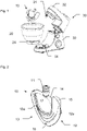
- the mixing tool 10 represented by figures 2 to 5 comprises a first mixing arm 12 which has a first width, greater than a second width of a second mixing arm 13, an opening 17 being formed between the first mixing arm 12 and the second mixing arm 13.
- the opening 17 is eccentric or offset with respect to the axis of rotation 100.
- the first mixing arm (due to the first width which is at least greater than 4 cm) can effectively incorporate the compositions one into the 'other.
- the second mixing arm 13 (whose second width is at least greater than 2.5 cm) provides additional mixing.
- the opening 17 is off-centre, so that this also contributes to additional mixing, due to the movement of the mixing tool 10 (in rotation around the axis of rotation 100, while following an epicyclic trajectory).
- the mixing tool 10 also comprises a fin 15, with a thickness advantageously between 0.5 and 1.2 cm, arranged on the upper part of the first mixing arm 12, to effectively bring the preparation back to the center of the rigid working container. .
- Each mixing arm 12 and 13 of the mixing tool 10 comprises a scraping lip 12a and 13a respectively formed from elastic or flexible material. Indeed, due to the epicyclic trajectory imposed on the mixing tool 10, each of the first mixing arm 12 and of the second mixing arm 13 comes regularly close to the rigid working container 20. The scraping lips 12a and 13a have then the effect of perfectly matching the wall of the rigid working container, to guarantee that all the preparation will be worked, even near the wall of the rigid working container 20.
- a notch 16 is provided between the scraper lip 12a and the scraper lip 13a, at the tip of the mixing tool 10, that is to say at the junction of the two mixing arms 12 and 13 at the level of the axis of rotation 100, so as to avoid tensile and/or shearing forces within the material forming the scraping lips 12a and 13a, which can then also wrap around each other in due to the rotational movement, and perfectly fit the bottom of the rigid working container 20.
- the mixing tool 10 typically comprises a metal frame 14 (stainless steel or aluminum), and it is typically possible to envisage forming the scraping lips 12a and 13a with silicone overmolded on the frame 14. We see for example, figure 6 , the frame 14 alone with orifices 14a to ensure good quality and grips the molded flexible material.
- the perimeter of the opening 17 is free of molded material, that is to say that it is the frame 14 which forms and defines the opening 17.
- the latter has the shape of a drop of water which points towards the upper end of the second mixing arm 13, which is the thinnest.
- the scraper lip may be detachable from the frame to allow its replacement.
Description
L'invention concerne de manière générale un outil mélangeur pour un appareil de préparation culinaire, et un appareil de préparation culinaire équipé d'un tel outil mélangeur. En particulier, l'invention concerne un outil mélangeur pour effectuer des mélanges ou incorporations de compositions avec des textures différentes, dont une des compositions est dite délicate (par exemple des blancs en neige à mélanger avec une sauce béchamel ou du chocolat liquide).The invention generally relates to a mixing tool for a food preparation appliance, and a food preparation appliance equipped with such a mixing tool. In particular, the invention relates to a mixing tool for mixing or incorporating compositions with different textures, one of the compositions of which is said to be delicate (for example egg whites to be mixed with a bechamel sauce or liquid chocolate).
Il est connu d'équiper des appareils de préparation culinaire d'outils mélangeurs pour effecteur automatiquement une opération de mélange mécanique, comme le montre le document
Un des buts de l'invention est de remédier aux inconvénients mentionnés ci-dessus, et en particulier de proposer un outil mélangeur bien adapté pour mélanger des préparations délicates, pour effectuer rapidement un mélange homogène, en limitant les battements ou brassages inutiles.One of the aims of the invention is to remedy the drawbacks mentioned above, and in particular to provide a mixing tool that is well suited to mixing delicate preparations, to rapidly produce a homogeneous mixture, by limiting unnecessary beating or mixing.
A cet effet, un premier aspect de l'invention concerne un outil mélangeur pour un appareil de préparation culinaire, comprenant :
- une tête d'entraînement agencée pour s'accoupler avec un entraîneur de l'appareil de préparation culinaire, de sorte à entraîner l'outil mélangeur en rotation autour d'un axe de rotation,
- au moins deux bras de mélange agencés de part et d'autre de l'axe de rotation, et présentant chacun une largeur prédéfinie de sorte à définir au moins une ouverture agencée entre les deux bras de mélange,
- a drive head arranged to couple with a driver of the food preparation appliance, so as to drive the mixing tool in rotation around an axis of rotation,
- at least two mixing arms arranged on either side of the axis of rotation, and each having a predefined width so as to define at least one opening arranged between the two mixing arms,
L'outil mélangeur selon la mise en œuvre ci-dessus présente deux bras de mélange de largeurs différentes, si bien que l'ouverture est excentrée par rapport à l'axe de rotation. En conséquence le premier bras de mélange (de largeur la plus importante) va permettre une bonne incorporation, en poussant efficacement un composé dans l'autre, et la présence de l'ouverture permet toutefois de brasser correctement la préparation pour homogénéiser cette dernière.The mixing tool according to the implementation above has two mixing arms of different widths, so that the opening is eccentric with respect to the axis of rotation. Consequently, the first mixing arm (of the largest width) will allow good incorporation, by effectively pushing one compound into the other, and the presence of the opening nevertheless makes it possible to mix the preparation correctly in order to homogenize the latter.
Avantageusement, l'outil mélangeur comprend une ailette agencée sur le premier bras de mélange, du côté de la tête d'entraînement. L'ailette selon la mise en œuvre ci-dessus permet de ramener la préparation sur elle-même, comme le ferait un brassage manuel avec un mouvement d'une spatule directement manipulée par un utilisateur.Advantageously, the mixing tool comprises a fin arranged on the first mixing arm, on the drive head side. The fin according to the implementation above makes it possible to bring the preparation back on itself, as manual stirring would do with a movement of a spatula directly manipulated by a user.
Avantageusement, l'ailette présente une largeur supérieure à la deuxième largeur.Advantageously, the fin has a width greater than the second width.
Avantageusement, l'ailette présente une largeur égale à la première largeur ± 15%. Autrement dit, l'ailette présente une largeur similaire ou égale à la première largeur du premier bras de mélange.Advantageously, the fin has a width equal to the first width ±15%. In other words, the fin has a width similar or equal to the first width of the first mixing arm.
Avantageusement, l'outil mélangeur comprend un cadre formant les bras de mélange et relié à la tête d'entraînement. Un tel cadre permet de procurer une résistance et une rigidité adéquates lors du brassage.Advantageously, the mixing tool comprises a frame forming the mixing arms and connected to the drive head. Such a frame makes it possible to provide adequate strength and rigidity during brewing.
Avantageusement, le cadre est un cadre fermé, entourant l'ouverture. En d'autres termes, l'ouverture est une ouverture fermée, c'est-à-dire présentant un périmètre fermé.Advantageously, the frame is a closed frame, surrounding the opening. In other words, the opening is a closed opening, that is to say having a closed perimeter.
Avantageusement, le cadre comprend, à l'opposé de la tête d'entraînement, une extrémité pointue formée par une jonction des bras de mélange. Une telle extrémité permet de bien s'adapter à la forme d'un récipient de travail de l'appareil de préparation culinaire, généralement en forme de bol.Advantageously, the frame comprises, opposite the drive head, a pointed end formed by a junction of the mixing arms. Such an end makes it possible to adapt well to the shape of a working receptacle of the food preparation appliance, generally bowl-shaped.
Avantageusement, le cadre est formé en acier inoxydable, ou en aluminium.Advantageously, the frame is formed from stainless steel, or aluminum.
Avantageusement, au moins l'un des bras de mélange comprend une lèvre de raclage. Une telle lèvre de raclage permet de garantir que toute la préparation sera travaillée, même à proximité du récipient de travail.Advantageously, at least one of the mixing arms comprises a scraper lip. Such a scraping lip makes it possible to guarantee that the whole preparation will be worked on, even near the working container.
Avantageusement, les deux bras de mélange comprennent une lèvre de raclage, qui sont séparées l'une de l'autre au niveau de l'extrémité pointue par une encoche. Une telle encoche permet de limiter les contraintes à la pointe de l'outil mélangeur, tout en offrant la possibilité aux lèvres de raclage de s'enrouler l'une sur l'autre.Advantageously, the two mixing arms comprise a scraper lip, which are separated from each other at the pointed end by a notch. Such a notch makes it possible to limit the stresses at the tip of the mixing tool, while offering the possibility for the scraping lips to wrap around each other.
Avantageusement, la lèvre de raclage est formée par une matière élastique surmoulée sur le cadre.Advantageously, the scraper lip is formed by an elastic material molded onto the frame.
Avantageusement, au moins une portion de périmètre de l'ouverture entre les bras de mélange est dépourvue de matière élastique surmoulée. En d'autres termes, l'ouverture est formée par le cadre lui-même et non par la matière de surmoulage.Advantageously, at least a perimeter portion of the opening between the mixing arms is devoid of overmoulded elastic material. In other words, the opening is formed by the frame itself and not by the overmolding material.
Avantageusement, l'ouverture présente un périmètre fermé, et le périmètre de l'ouverture entre les bras de mélange est entièrement dépourvu de matière élastique surmoulée.Advantageously, the opening has a closed perimeter, and the perimeter of the opening between the mixing arms is entirely devoid of overmoulded elastic material.
Avantageusement, la matière élastique surmoulée est formée par du silicone d'épaisseur 2 mm ± 0.5 mm au niveau des bras de mélange.Advantageously, the overmolded elastic material is formed by silicone with a thickness of 2 mm ± 0.5 mm at the level of the mixing arms.
Avantageusement, la matière élastique surmoulée présente une dureté de 60 Shore A ± 5 Shore A.Advantageously, the overmolded elastic material has a hardness of 60 Shore A ± 5 Shore A.
Selon l'invention, les bras de mélange sont formés dans un plan contenant l'axe de rotation. L'outil mélangeur est alors de forme généralement plate.According to the invention, the mixing arms are formed in a plane containing the axis of rotation. The mixing tool is then generally flat in shape.
Avantageusement, l'outil mélangeur comprend deux bras de mélange. Cela permet de limiter les sollicitations mécaniques sur la préparation.Advantageously, the mixing tool comprises two mixing arms. This makes it possible to limit the mechanical stresses on the preparation.
Avantageusement, l'ouverture présente une portion de périmètre incurvée du côté des bras de mélange, et une portion de périmètre rectiligne du côté de la tête d'entraînement. Autrement dit, l'ouverture suit la forme extérieure de l'outil mélangeur.Advantageously, the opening has a curved perimeter portion on the mixing arm side, and a rectilinear perimeter portion on the drive head side. In other words, the opening follows the outer shape of the mixing tool.
Avantageusement, l'ouverture est décalée par rapport à l'axe de rotation.Advantageously, the opening is offset with respect to the axis of rotation.
Avantageusement, l'ouverture est asymétrique par rapport à l'axe de rotation.Advantageously, the opening is asymmetrical with respect to the axis of rotation.
Un deuxième aspect de l'invention concerne un appareil de préparation culinaire, comprenant :
- un outil mélangeur selon le premier aspect de l'invention,
- un entraîneur, agencé pour s'accoupler avec la tête d'entraînement de l'outil mélangeur,
- a mixing tool according to the first aspect of the invention,
- a drive, arranged to couple with the drive head of the mixing tool,
Avantageusement, l'appareil de préparation culinaire comprend un récipient agencé pour recevoir des aliments à préparer, dans lequel les bras de mélange de l'outil mélangeur sont agencés pour racler une paroi du récipient.Advantageously, the food preparation appliance comprises a container arranged to receive food to be prepared, in which the mixing arms of the mixing tool are arranged to scrape a wall of the container.
Avantageusement, l'appareil de préparation culinaire comprend une unité d'entraînement avec un train d'engrenage épicycloïdal.Advantageously, the food preparation appliance comprises a drive unit with an epicyclic gear train.
Avantageusement, la première largeur du premier bras de mélange (y compris la lèvre de raclage) est supérieure à une valeur comprise dans une gamme de valeurs allant de 2 cm à 5 cm.Advantageously, the first width of the first mixing arm (including the scraping lip) is greater than a value included in a range of values ranging from 2 cm to 5 cm.
Avantageusement, la deuxième largeur du deuxième bras de mélange (y compris la lèvre de raclage) est supérieure à une valeur comprise dans une gamme de valeurs allant de 1 cm à 3 cm.Advantageously, the second width of the second mixing arm (including the scraping lip) is greater than a value included in a range of values ranging from 1 cm to 3 cm.
Avantageusement, l'ouverture occupe une position excentrée sur le cadre.Advantageously, the opening occupies an eccentric position on the frame.
Avantageusement, l'ouverture présente une section de passage supérieure à 30 cm2.Advantageously, the opening has a passage section greater than 30 cm 2 .
Avantageusement, l'ouverture présente une forme globale ovoïde, la pointe étant orientée vers le sommet du deuxième bras de mélange.Advantageously, the opening has an overall ovoid shape, the tip being oriented towards the top of the second mixing arm.
D'autres caractéristiques et avantages de la présente invention apparaîtront plus clairement à la lecture de la description détaillée qui suit d'un mode de réalisation de l'invention donné à titre d'exemple nullement limitatif et illustré par les dessins annexés, dans lesquels :
- la
figure 1 représente une vue d'ensemble éclatée en perspective d'un appareil de préparation culinaire comprenant un outil mélangeur selon la présente invention ; - les
figures 2 à 5 représentent des vues de l'outil mélangeur de lafigure 1 ; - la
figure 6 représente une vue d'un cadre constitutif de l'outil mélangeur de lafigure 1 .
- the
figure 1 shows an exploded overall view in perspective of a food preparation appliance comprising a mixing tool according to the present invention; - them
figures 2 to 5 represent views of the mixer tool of thefigure 1 ; - the
figure 6 represents a view of a constituent frame of the mixer tool of thefigure 1 .
La
L'unité d'entraînement 32 peut comprendre un train d'engrenage épicycloïdal, pour entraîner l'outil mélangeur 10 en rotation autour d'un axe de rotation 100 (visible
L'outil mélangeur 10 est agencé pour travailler des aliments à travailler reçus dans le récipient rigide de travail 20. A cet effet, le boîtier de l'appareil de préparation culinaire 30 est articulé, pour permettre de faire plonger l'outil mélangeur 10 dans le récipient rigide de travail 20, ou l'en dégager.The mixing
On peut noter que le récipient rigide de travail 20 comprend des moyens de verrouillage sur le boitier de l'appareil de préparation culinaire 30, via des plots 24 qui s'engagent dans des rainures 34 (pour former typiquement un accouplement de type baïonnette), afin de procurer un blocage (en rotation et en translation verticale) du récipient rigide de travail 20.It may be noted that the rigid working
Enfin, l'appareil de préparation culinaire 30 comprend une interface homme machine 33 pour commander le fonctionnement (marche-arrêt, sélection de programme...).Finally, the
Lors d'un programme de mélange de deux compositions dont une délicate pour réaliser une préparation délicate, l'invention propose d'utiliser l'outil mélangeur 10, pour obtenir rapidement un mélange homogène, tout en travaillant (par mélange mécanique ou malaxage...) le moins longtemps et le moins vite possible cette préparation délicate.During a program for mixing two compositions, one of which is delicate, to produce a delicate preparation, the invention proposes using the
A cet effet, l'outil mélangeur 10 représenté des
En conséquence, comme on le voit bien
Comme vu ci-dessus, l'ouverture 17 est excentrée, si bien que cela contribue également à effectuer un mélange supplémentaire, en raison du mouvement de l'outil mélangeur 10 (en rotation autour de l'axe de rotation 100, tout en suivant une trajectoire épicycloïdale).As seen above, the
L'outil mélangeur 10 comprend également une ailette 15, d'épaisseur avantageusement comprise entre 0,5 et 1,2 cm, agencée sur la partie supérieure du premier bras de mélange 12, pour ramener efficacement la préparation au centre du récipient rigide de travail.The mixing
Chaque bras de mélange 12 et 13 de l'outil mélangeur 10 comprend une lèvre de raclage 12a et 13a respectivement formée en matériau élastique ou souple. En effet, en raison de la trajectoire épicycloïdale imposée à l'outil mélangeur 10, chacun du premier bras de mélange 12 et du deuxième bras de mélange 13 vient régulièrement à proximité du récipient rigide de travail 20. Les lèvres de raclage 12a et 13a ont alors pour effet d'épouser parfaitement la paroi du récipient rigide de travail, pour garantir que toute la préparation sera travaillée, même à proximité de la paroi du récipient rigide de travail 20.Each mixing
De plus, visible
L'outil mélangeur 10 comprend typiquement un cadre 14 métallique (en acier inoxydable ou en aluminium), et on peut typiquement envisager de former les lèvres de raclage 12a et 13a avec du silicone surmoulé sur le cadre 14. On voit par exemple,
Selon un mode de réalisation représenté, le périmètre de l'ouverture 17 est exempt de matière surmoulée, c'est-à-dire que c'est le cadre 14 qui forme et définit l'ouverture 17. Cette dernière présente une forme de goutte d'eau qui pointe vers l'extrémité supérieure du deuxième bras de mélange 13, qui est le plus fin.According to one embodiment shown, the perimeter of the
On comprendra que diverses modifications et/ou améliorations évidentes pour l'homme du métier peuvent être apportées aux différents modes de réalisation de l'invention décrits dans la présente description sans sortir du cadre de l'invention défini par les revendications annexées.It will be understood that various modifications and/or improvements obvious to those skilled in the art can be made to the various embodiments of the invention described in the present description without departing from the scope of the invention defined by the appended claims.
Ainsi dans une variante de réalisation non représentée, la lèvre de raclage pourra être détachable du cadre pour permettre son remplacement.Thus in a variant embodiment not shown, the scraper lip may be detachable from the frame to allow its replacement.
Claims (14)
- Mixing tool (10) for a food preparation appliance (30), comprising:- a driving head (11) arranged such that it couples to a driver (31) of the food preparation appliance in such a way as to rotate the mixing tool (10) about a rotational axis (100),- at least two mixing arms (12, 13) arranged either side of the rotational axis (100), and formed in a plane containing the rotational axis, the two mixing arms (12, 13) each having, in said plane, a width which is predefined so as to define at least one opening (17) arranged between the two mixing arms (12, 13),- a first mixing arm (12) having a first width and a second mixing arm (13) having a second width, which is shorter than the first width, characterised in that- the first width of the first mixing arm is longer than 4cm,- the second width of the second mixing arm is longer than 2.5cm.
- Mixing tool (10) according to the preceding claim, comprising a blade (15) arranged on the first mixing arm (12), on the side of the driving head (11).
- Mixing tool (10) according to one of the preceding claims, comprising a frame (14) forming the mixing arms (12, 13) and connected to the driving head (11).
- Mixing tool (10) according to claim 3, wherein the frame (14) comprises, opposite the driving head (11), a sharp end formed by a joining of the mixing arms (12, 13).
- Mixing tool (10) according to one of claims 3 or 4, wherein the frame (14) is formed of stainless steel, or of aluminium.
- Mixing tool (10) according to one of the preceding claims, wherein at least one of the mixing arms (12, 13) comprises a scraping lip (12a, 13a).
- Mixing tool (10) according to the preceding claim, dependent on claim 4, wherein the two mixing arms (12, 13) comprise a scraping lip (12a, 13a), which are separated from one another at the sharp end by a notch (16).
- Mixing tool (10) according to one of claims 6 or 7, wherein the scraping lip (12a, 13a) is formed by an elastic material overmoulded on the frame (14).
- Mixing tool (10) according to the preceding claim, wherein at least one perimeter portion of the opening (17) between the mixing arms has no overmoulded elastic material.
- Mixing tool (10) according to one of claims 8 or 9, wherein the opening (17) has a closed perimeter, and wherein the perimeter of the opening (17) between the mixing arms has completely no overmoulded elastic material.
- Mixing tool (10) according to one of claims 8 to 10, wherein the overmoulded elastic material is formed by silicone of thickness 2mm ± 0.5mm at the mixing arms.
- Mixing tool (10) according to one of claims 8 to 11, wherein the overmoulded elastic material has a hardness of 60 Shore A ± 5 Shore A.
- Mixing tool (10) according to one of the preceding claims, wherein the opening (17) has a curved perimeter portion on the side of the mixing arms, and a rectilinear perimeter portion on the side of the driving head (11).
- Food preparation appliance (30), comprising:- a mixing tool (10) according to one of the preceding claims,- a driver (31), arranged such that it couples to the driving head (11) of the mixing tool (10),wherein the driver (31) is arranged to rotate the mixing tool (10), along an epicyclic trajectory.
Applications Claiming Priority (2)
| Application Number | Priority Date | Filing Date | Title |
|---|---|---|---|
| FR1852704A FR3079400B1 (en) | 2018-03-28 | 2018-03-28 | BLENDING TOOL FOR FOOD PREPARATION APPLIANCE |
| PCT/EP2019/055920 WO2019185333A1 (en) | 2018-03-28 | 2019-03-08 | Miixing tool for a food preparation appliance |
Publications (2)
| Publication Number | Publication Date |
|---|---|
| EP3774010A1 EP3774010A1 (en) | 2021-02-17 |
| EP3774010B1 true EP3774010B1 (en) | 2022-12-28 |
Family
ID=62816722
Family Applications (1)
| Application Number | Title | Priority Date | Filing Date |
|---|---|---|---|
| EP19709726.4A Active EP3774010B1 (en) | 2018-03-28 | 2019-03-08 | Miixing tool for a food preparation appliance |
Country Status (4)
| Country | Link |
|---|---|
| EP (1) | EP3774010B1 (en) |
| CN (2) | CN110313850A (en) |
| FR (1) | FR3079400B1 (en) |
| WO (1) | WO2019185333A1 (en) |
Families Citing this family (1)
| Publication number | Priority date | Publication date | Assignee | Title |
|---|---|---|---|---|
| FR3079400B1 (en) * | 2018-03-28 | 2022-07-22 | Seb Sa | BLENDING TOOL FOR FOOD PREPARATION APPLIANCE |
Family Cites Families (14)
| Publication number | Priority date | Publication date | Assignee | Title |
|---|---|---|---|---|
| DE952521C (en) * | 1937-11-02 | 1956-11-15 | Hobart Mfg Co | Device for the stable connection of the troughs of small machines for food processing with their bases |
| CH298124A (en) * | 1951-01-20 | 1954-04-30 | Moeller Reinhold | Mixing and kneading machine for various purposes, especially in the luxury food industry. |
| IT1234310B (en) * | 1989-07-07 | 1992-05-15 | Vittorio Falchetti | MIXER FOR DYEING SOLUTIONS AND OTHER MIXTURES FOR COSMETIC USE. |
| WO2006083560A2 (en) * | 2005-01-31 | 2006-08-10 | Louis Busick | Mixer blade attachment with flexible fins |
| EP2201997B1 (en) * | 2006-07-13 | 2013-02-20 | Premark FEG L.L.C. | Beater for mixing |
| US7740401B2 (en) * | 2007-04-16 | 2010-06-22 | Vita-Mix Corporation | Food mixing machine and agitator therefor |
| GB2470914B (en) * | 2009-06-09 | 2014-04-09 | Kenwood Ltd | Beater assembly for a stand mixer |
| GB2480302A (en) * | 2010-05-13 | 2011-11-16 | Kenwood Ltd | Beater assembly |
| CN101837257B (en) * | 2010-05-20 | 2012-07-18 | 钟荣华 | Fluid stirring paddle |
| US8616763B2 (en) * | 2010-10-05 | 2013-12-31 | Whirlpool Corporation | Stand mixer wiping beater with additional features |
| AU2013277942B2 (en) * | 2012-06-22 | 2018-03-01 | Breville Pty Limited | Improved bench mixer |
| SI2702912T1 (en) * | 2012-08-27 | 2016-07-29 | Bsh Hausgeraete Gmbh | Kitchen device with working tool |
| GB2544966A (en) * | 2015-11-25 | 2017-06-07 | Kenwood Ltd | Tool |
| FR3079400B1 (en) * | 2018-03-28 | 2022-07-22 | Seb Sa | BLENDING TOOL FOR FOOD PREPARATION APPLIANCE |
-
2018
- 2018-03-28 FR FR1852704A patent/FR3079400B1/en active Active
-
2019
- 2019-03-08 WO PCT/EP2019/055920 patent/WO2019185333A1/en unknown
- 2019-03-08 EP EP19709726.4A patent/EP3774010B1/en active Active
- 2019-03-27 CN CN201910236463.0A patent/CN110313850A/en active Pending
- 2019-03-27 CN CN201920396960.2U patent/CN210185401U/en active Active
Also Published As
| Publication number | Publication date |
|---|---|
| FR3079400B1 (en) | 2022-07-22 |
| WO2019185333A1 (en) | 2019-10-03 |
| EP3774010A1 (en) | 2021-02-17 |
| CN110313850A (en) | 2019-10-11 |
| CN210185401U (en) | 2020-03-27 |
| FR3079400A1 (en) | 2019-10-04 |
Similar Documents
| Publication | Publication Date | Title |
|---|---|---|
| EP2060216B1 (en) | Electrical kitchen appliance comprising a support for a mixing element | |
| EP2516046B1 (en) | Kitchen appliance, in particular for preparing flour-based dough | |
| EP2533647B1 (en) | Device for culinary preparation using a mixture of ingredients contained in said device, and integrated measurement of the temperature of the mixture, and method for regulation said device | |
| EP1858633B1 (en) | Blender-type electrical cooking appliance comprising a stirrer | |
| EP0328590B2 (en) | Auxiliary work bowl for kitchen mixer | |
| EP2522262B1 (en) | Mixing tool for working container of a household cooking appliance | |
| EP3774010B1 (en) | Miixing tool for a food preparation appliance | |
| EP2206455A1 (en) | Household cooking appliance including a first and second working container on a case | |
| CA2281612A1 (en) | Electrical household appliance for cooking preparation, such as multipurpose domestic robot, and multipurpose working container | |
| EP2892405B1 (en) | Household food preparation apparatus comprising a dough-mixing hook driven in a planetary motion | |
| EP1483997B1 (en) | Rotating working appliance for the preparation of drinks in a food processor | |
| EP0216836B1 (en) | Kneading apparatus transformable into a mixer and a beater | |
| EP2870902B1 (en) | Emulsifier-stirrer tool for blender and hand-held blender provided with such a tool | |
| WO2002003842A1 (en) | Housing for electrical household cooking appliance designed to be hand-held in different positions | |
| FR2597321A1 (en) | Electric household appliance for preparing sauces | |
| FR2994816A1 (en) | TRANSFORMABLE KITCHEN ROBOT INCORPORATING A MANUAL ACTUATION MECHANISM | |
| EP3773094A1 (en) | Flexible vessel for a food-preparation appliance | |
| FR2886831A1 (en) | Rotary blender for mixing e.g. meat, has cell supplying motor unit which drives S-shaped or pick-shaped agitator, where agitator is in connection with lid so as to mix food in stewpot or permit cooking of meat fixed to pick-shaped agitator | |
| WO2024033105A1 (en) | Working bowl for a food preparation appliance | |
| FR2474853A1 (en) | Food emulsifier moving container - consists of container with pivot mounted mixer blade inside it, screw driven through lid | |
| FR3139452A1 (en) | Food preparation device for a food preparation appliance | |
| WO2015140414A1 (en) | Convertible food processor |
Legal Events
| Date | Code | Title | Description |
|---|---|---|---|
| STAA | Information on the status of an ep patent application or granted ep patent |
Free format text: STATUS: UNKNOWN |
|
| STAA | Information on the status of an ep patent application or granted ep patent |
Free format text: STATUS: THE INTERNATIONAL PUBLICATION HAS BEEN MADE |
|
| PUAI | Public reference made under article 153(3) epc to a published international application that has entered the european phase |
Free format text: ORIGINAL CODE: 0009012 |
|
| STAA | Information on the status of an ep patent application or granted ep patent |
Free format text: STATUS: REQUEST FOR EXAMINATION WAS MADE |
|
| 17P | Request for examination filed |
Effective date: 20201016 |
|
| AK | Designated contracting states |
Kind code of ref document: A1 Designated state(s): AL AT BE BG CH CY CZ DE DK EE ES FI FR GB GR HR HU IE IS IT LI LT LU LV MC MK MT NL NO PL PT RO RS SE SI SK SM TR |
|
| AX | Request for extension of the european patent |
Extension state: BA ME |
|
| DAV | Request for validation of the european patent (deleted) | ||
| DAX | Request for extension of the european patent (deleted) | ||
| REG | Reference to a national code |
Ref country code: DE Ref legal event code: R079 Ref document number: 602019023665 Country of ref document: DE Free format text: PREVIOUS MAIN CLASS: B01F0007000000 Ipc: A47J0043070000 |
|
| GRAP | Despatch of communication of intention to grant a patent |
Free format text: ORIGINAL CODE: EPIDOSNIGR1 |
|
| STAA | Information on the status of an ep patent application or granted ep patent |
Free format text: STATUS: GRANT OF PATENT IS INTENDED |
|
| RIC1 | Information provided on ipc code assigned before grant |
Ipc: A47J 43/07 20060101AFI20220617BHEP |
|
| INTG | Intention to grant announced |
Effective date: 20220720 |
|
| GRAS | Grant fee paid |
Free format text: ORIGINAL CODE: EPIDOSNIGR3 |
|
| GRAA | (expected) grant |
Free format text: ORIGINAL CODE: 0009210 |
|
| STAA | Information on the status of an ep patent application or granted ep patent |
Free format text: STATUS: THE PATENT HAS BEEN GRANTED |
|
| AK | Designated contracting states |
Kind code of ref document: B1 Designated state(s): AL AT BE BG CH CY CZ DE DK EE ES FI FR GB GR HR HU IE IS IT LI LT LU LV MC MK MT NL NO PL PT RO RS SE SI SK SM TR |
|
| REG | Reference to a national code |
Ref country code: GB Ref legal event code: FG4D Free format text: NOT ENGLISH |
|
| REG | Reference to a national code |
Ref country code: CH Ref legal event code: EP |
|
| REG | Reference to a national code |
Ref country code: DE Ref legal event code: R096 Ref document number: 602019023665 Country of ref document: DE |
|
| REG | Reference to a national code |
Ref country code: AT Ref legal event code: REF Ref document number: 1539909 Country of ref document: AT Kind code of ref document: T Effective date: 20230115 |
|
| REG | Reference to a national code |
Ref country code: IE Ref legal event code: FG4D Free format text: LANGUAGE OF EP DOCUMENT: FRENCH |
|
| REG | Reference to a national code |
Ref country code: LT Ref legal event code: MG9D |
|
| PG25 | Lapsed in a contracting state [announced via postgrant information from national office to epo] |
Ref country code: SE Free format text: LAPSE BECAUSE OF FAILURE TO SUBMIT A TRANSLATION OF THE DESCRIPTION OR TO PAY THE FEE WITHIN THE PRESCRIBED TIME-LIMIT Effective date: 20221228 Ref country code: NO Free format text: LAPSE BECAUSE OF FAILURE TO SUBMIT A TRANSLATION OF THE DESCRIPTION OR TO PAY THE FEE WITHIN THE PRESCRIBED TIME-LIMIT Effective date: 20230328 Ref country code: LT Free format text: LAPSE BECAUSE OF FAILURE TO SUBMIT A TRANSLATION OF THE DESCRIPTION OR TO PAY THE FEE WITHIN THE PRESCRIBED TIME-LIMIT Effective date: 20221228 Ref country code: FI Free format text: LAPSE BECAUSE OF FAILURE TO SUBMIT A TRANSLATION OF THE DESCRIPTION OR TO PAY THE FEE WITHIN THE PRESCRIBED TIME-LIMIT Effective date: 20221228 |
|
| PGFP | Annual fee paid to national office [announced via postgrant information from national office to epo] |
Ref country code: FR Payment date: 20230320 Year of fee payment: 5 |
|
| REG | Reference to a national code |
Ref country code: NL Ref legal event code: MP Effective date: 20221228 |
|
| REG | Reference to a national code |
Ref country code: AT Ref legal event code: MK05 Ref document number: 1539909 Country of ref document: AT Kind code of ref document: T Effective date: 20221228 |
|
| PG25 | Lapsed in a contracting state [announced via postgrant information from national office to epo] |
Ref country code: RS Free format text: LAPSE BECAUSE OF FAILURE TO SUBMIT A TRANSLATION OF THE DESCRIPTION OR TO PAY THE FEE WITHIN THE PRESCRIBED TIME-LIMIT Effective date: 20221228 Ref country code: LV Free format text: LAPSE BECAUSE OF FAILURE TO SUBMIT A TRANSLATION OF THE DESCRIPTION OR TO PAY THE FEE WITHIN THE PRESCRIBED TIME-LIMIT Effective date: 20221228 Ref country code: HR Free format text: LAPSE BECAUSE OF FAILURE TO SUBMIT A TRANSLATION OF THE DESCRIPTION OR TO PAY THE FEE WITHIN THE PRESCRIBED TIME-LIMIT Effective date: 20221228 Ref country code: GR Free format text: LAPSE BECAUSE OF FAILURE TO SUBMIT A TRANSLATION OF THE DESCRIPTION OR TO PAY THE FEE WITHIN THE PRESCRIBED TIME-LIMIT Effective date: 20230329 |
|
| PGFP | Annual fee paid to national office [announced via postgrant information from national office to epo] |
Ref country code: IT Payment date: 20230307 Year of fee payment: 5 Ref country code: DE Payment date: 20230307 Year of fee payment: 5 |
|
| P01 | Opt-out of the competence of the unified patent court (upc) registered |
Effective date: 20230517 |
|
| PG25 | Lapsed in a contracting state [announced via postgrant information from national office to epo] |
Ref country code: NL Free format text: LAPSE BECAUSE OF FAILURE TO SUBMIT A TRANSLATION OF THE DESCRIPTION OR TO PAY THE FEE WITHIN THE PRESCRIBED TIME-LIMIT Effective date: 20221228 |
|
| PG25 | Lapsed in a contracting state [announced via postgrant information from national office to epo] |
Ref country code: SM Free format text: LAPSE BECAUSE OF FAILURE TO SUBMIT A TRANSLATION OF THE DESCRIPTION OR TO PAY THE FEE WITHIN THE PRESCRIBED TIME-LIMIT Effective date: 20221228 Ref country code: RO Free format text: LAPSE BECAUSE OF FAILURE TO SUBMIT A TRANSLATION OF THE DESCRIPTION OR TO PAY THE FEE WITHIN THE PRESCRIBED TIME-LIMIT Effective date: 20221228 Ref country code: PT Free format text: LAPSE BECAUSE OF FAILURE TO SUBMIT A TRANSLATION OF THE DESCRIPTION OR TO PAY THE FEE WITHIN THE PRESCRIBED TIME-LIMIT Effective date: 20230428 Ref country code: ES Free format text: LAPSE BECAUSE OF FAILURE TO SUBMIT A TRANSLATION OF THE DESCRIPTION OR TO PAY THE FEE WITHIN THE PRESCRIBED TIME-LIMIT Effective date: 20221228 Ref country code: EE Free format text: LAPSE BECAUSE OF FAILURE TO SUBMIT A TRANSLATION OF THE DESCRIPTION OR TO PAY THE FEE WITHIN THE PRESCRIBED TIME-LIMIT Effective date: 20221228 Ref country code: CZ Free format text: LAPSE BECAUSE OF FAILURE TO SUBMIT A TRANSLATION OF THE DESCRIPTION OR TO PAY THE FEE WITHIN THE PRESCRIBED TIME-LIMIT Effective date: 20221228 Ref country code: AT Free format text: LAPSE BECAUSE OF FAILURE TO SUBMIT A TRANSLATION OF THE DESCRIPTION OR TO PAY THE FEE WITHIN THE PRESCRIBED TIME-LIMIT Effective date: 20221228 |
|
| PG25 | Lapsed in a contracting state [announced via postgrant information from national office to epo] |
Ref country code: SK Free format text: LAPSE BECAUSE OF FAILURE TO SUBMIT A TRANSLATION OF THE DESCRIPTION OR TO PAY THE FEE WITHIN THE PRESCRIBED TIME-LIMIT Effective date: 20221228 Ref country code: PL Free format text: LAPSE BECAUSE OF FAILURE TO SUBMIT A TRANSLATION OF THE DESCRIPTION OR TO PAY THE FEE WITHIN THE PRESCRIBED TIME-LIMIT Effective date: 20221228 Ref country code: IS Free format text: LAPSE BECAUSE OF FAILURE TO SUBMIT A TRANSLATION OF THE DESCRIPTION OR TO PAY THE FEE WITHIN THE PRESCRIBED TIME-LIMIT Effective date: 20230428 Ref country code: AL Free format text: LAPSE BECAUSE OF FAILURE TO SUBMIT A TRANSLATION OF THE DESCRIPTION OR TO PAY THE FEE WITHIN THE PRESCRIBED TIME-LIMIT Effective date: 20221228 |
|
| REG | Reference to a national code |
Ref country code: DE Ref legal event code: R097 Ref document number: 602019023665 Country of ref document: DE |
|
| PG25 | Lapsed in a contracting state [announced via postgrant information from national office to epo] |
Ref country code: MC Free format text: LAPSE BECAUSE OF FAILURE TO SUBMIT A TRANSLATION OF THE DESCRIPTION OR TO PAY THE FEE WITHIN THE PRESCRIBED TIME-LIMIT Effective date: 20221228 Ref country code: DK Free format text: LAPSE BECAUSE OF FAILURE TO SUBMIT A TRANSLATION OF THE DESCRIPTION OR TO PAY THE FEE WITHIN THE PRESCRIBED TIME-LIMIT Effective date: 20221228 |
|
| REG | Reference to a national code |
Ref country code: CH Ref legal event code: PL |
|
| PLBE | No opposition filed within time limit |
Free format text: ORIGINAL CODE: 0009261 |
|
| STAA | Information on the status of an ep patent application or granted ep patent |
Free format text: STATUS: NO OPPOSITION FILED WITHIN TIME LIMIT |
|
| GBPC | Gb: european patent ceased through non-payment of renewal fee |
Effective date: 20230328 |
|
| REG | Reference to a national code |
Ref country code: BE Ref legal event code: MM Effective date: 20230331 |
|
| 26N | No opposition filed |
Effective date: 20230929 |
|
| PG25 | Lapsed in a contracting state [announced via postgrant information from national office to epo] |
Ref country code: LU Free format text: LAPSE BECAUSE OF NON-PAYMENT OF DUE FEES Effective date: 20230308 |
|
| REG | Reference to a national code |
Ref country code: IE Ref legal event code: MM4A |
|
| PG25 | Lapsed in a contracting state [announced via postgrant information from national office to epo] |
Ref country code: GB Free format text: LAPSE BECAUSE OF NON-PAYMENT OF DUE FEES Effective date: 20230328 |
|
| PG25 | Lapsed in a contracting state [announced via postgrant information from national office to epo] |
Ref country code: SI Free format text: LAPSE BECAUSE OF FAILURE TO SUBMIT A TRANSLATION OF THE DESCRIPTION OR TO PAY THE FEE WITHIN THE PRESCRIBED TIME-LIMIT Effective date: 20221228 Ref country code: LI Free format text: LAPSE BECAUSE OF NON-PAYMENT OF DUE FEES Effective date: 20230331 Ref country code: IE Free format text: LAPSE BECAUSE OF NON-PAYMENT OF DUE FEES Effective date: 20230308 Ref country code: GB Free format text: LAPSE BECAUSE OF NON-PAYMENT OF DUE FEES Effective date: 20230328 Ref country code: CH Free format text: LAPSE BECAUSE OF NON-PAYMENT OF DUE FEES Effective date: 20230331 |
|
| PG25 | Lapsed in a contracting state [announced via postgrant information from national office to epo] |
Ref country code: BE Free format text: LAPSE BECAUSE OF NON-PAYMENT OF DUE FEES Effective date: 20230331 |