EP3773880B1 - Therapeutic modulation to treat blood glucose abnormalities, including type 2 diabetes, and/or reduce hba1c levels - Google Patents
Therapeutic modulation to treat blood glucose abnormalities, including type 2 diabetes, and/or reduce hba1c levels Download PDFInfo
- Publication number
- EP3773880B1 EP3773880B1 EP19777482.1A EP19777482A EP3773880B1 EP 3773880 B1 EP3773880 B1 EP 3773880B1 EP 19777482 A EP19777482 A EP 19777482A EP 3773880 B1 EP3773880 B1 EP 3773880B1
- Authority
- EP
- European Patent Office
- Prior art keywords
- patient
- signal
- methods
- blood glucose
- systems
- Prior art date
- Legal status (The legal status is an assumption and is not a legal conclusion. Google has not performed a legal analysis and makes no representation as to the accuracy of the status listed.)
- Active
Links
Images





Classifications
-
- A—HUMAN NECESSITIES
- A61—MEDICAL OR VETERINARY SCIENCE; HYGIENE
- A61N—ELECTROTHERAPY; MAGNETOTHERAPY; RADIATION THERAPY; ULTRASOUND THERAPY
- A61N1/00—Electrotherapy; Circuits therefor
- A61N1/02—Details
- A61N1/04—Electrodes
- A61N1/05—Electrodes for implantation or insertion into the body, e.g. heart electrode
- A61N1/0551—Spinal or peripheral nerve electrodes
-
- A—HUMAN NECESSITIES
- A61—MEDICAL OR VETERINARY SCIENCE; HYGIENE
- A61N—ELECTROTHERAPY; MAGNETOTHERAPY; RADIATION THERAPY; ULTRASOUND THERAPY
- A61N1/00—Electrotherapy; Circuits therefor
- A61N1/02—Details
- A61N1/04—Electrodes
- A61N1/05—Electrodes for implantation or insertion into the body, e.g. heart electrode
- A61N1/0551—Spinal or peripheral nerve electrodes
- A61N1/0553—Paddle shaped electrodes, e.g. for laminotomy
-
- A—HUMAN NECESSITIES
- A61—MEDICAL OR VETERINARY SCIENCE; HYGIENE
- A61N—ELECTROTHERAPY; MAGNETOTHERAPY; RADIATION THERAPY; ULTRASOUND THERAPY
- A61N1/00—Electrotherapy; Circuits therefor
- A61N1/02—Details
- A61N1/04—Electrodes
- A61N1/05—Electrodes for implantation or insertion into the body, e.g. heart electrode
- A61N1/0551—Spinal or peripheral nerve electrodes
- A61N1/0558—Anchoring or fixation means therefor
-
- A—HUMAN NECESSITIES
- A61—MEDICAL OR VETERINARY SCIENCE; HYGIENE
- A61N—ELECTROTHERAPY; MAGNETOTHERAPY; RADIATION THERAPY; ULTRASOUND THERAPY
- A61N1/00—Electrotherapy; Circuits therefor
- A61N1/18—Applying electric currents by contact electrodes
- A61N1/32—Applying electric currents by contact electrodes alternating or intermittent currents
- A61N1/36—Applying electric currents by contact electrodes alternating or intermittent currents for stimulation
- A61N1/3605—Implantable neurostimulators for stimulating central or peripheral nerve system
- A61N1/36128—Control systems
- A61N1/36135—Control systems using physiological parameters
-
- A—HUMAN NECESSITIES
- A61—MEDICAL OR VETERINARY SCIENCE; HYGIENE
- A61N—ELECTROTHERAPY; MAGNETOTHERAPY; RADIATION THERAPY; ULTRASOUND THERAPY
- A61N1/00—Electrotherapy; Circuits therefor
- A61N1/18—Applying electric currents by contact electrodes
- A61N1/32—Applying electric currents by contact electrodes alternating or intermittent currents
- A61N1/36—Applying electric currents by contact electrodes alternating or intermittent currents for stimulation
- A61N1/3605—Implantable neurostimulators for stimulating central or peripheral nerve system
- A61N1/36128—Control systems
- A61N1/36146—Control systems specified by the stimulation parameters
- A61N1/36167—Timing, e.g. stimulation onset
- A61N1/36171—Frequency
-
- A—HUMAN NECESSITIES
- A61—MEDICAL OR VETERINARY SCIENCE; HYGIENE
- A61N—ELECTROTHERAPY; MAGNETOTHERAPY; RADIATION THERAPY; ULTRASOUND THERAPY
- A61N1/00—Electrotherapy; Circuits therefor
- A61N1/18—Applying electric currents by contact electrodes
- A61N1/32—Applying electric currents by contact electrodes alternating or intermittent currents
- A61N1/36—Applying electric currents by contact electrodes alternating or intermittent currents for stimulation
- A61N1/3605—Implantable neurostimulators for stimulating central or peripheral nerve system
- A61N1/36128—Control systems
- A61N1/36146—Control systems specified by the stimulation parameters
- A61N1/36167—Timing, e.g. stimulation onset
- A61N1/36175—Pulse width or duty cycle
-
- A—HUMAN NECESSITIES
- A61—MEDICAL OR VETERINARY SCIENCE; HYGIENE
- A61N—ELECTROTHERAPY; MAGNETOTHERAPY; RADIATION THERAPY; ULTRASOUND THERAPY
- A61N1/00—Electrotherapy; Circuits therefor
- A61N1/18—Applying electric currents by contact electrodes
- A61N1/32—Applying electric currents by contact electrodes alternating or intermittent currents
- A61N1/36—Applying electric currents by contact electrodes alternating or intermittent currents for stimulation
- A61N1/36007—Applying electric currents by contact electrodes alternating or intermittent currents for stimulation of urogenital or gastrointestinal organs, e.g. for incontinence control
-
- A—HUMAN NECESSITIES
- A61—MEDICAL OR VETERINARY SCIENCE; HYGIENE
- A61N—ELECTROTHERAPY; MAGNETOTHERAPY; RADIATION THERAPY; ULTRASOUND THERAPY
- A61N1/00—Electrotherapy; Circuits therefor
- A61N1/18—Applying electric currents by contact electrodes
- A61N1/32—Applying electric currents by contact electrodes alternating or intermittent currents
- A61N1/36—Applying electric currents by contact electrodes alternating or intermittent currents for stimulation
- A61N1/3605—Implantable neurostimulators for stimulating central or peripheral nerve system
- A61N1/3606—Implantable neurostimulators for stimulating central or peripheral nerve system adapted for a particular treatment
- A61N1/36062—Spinal stimulation
-
- A—HUMAN NECESSITIES
- A61—MEDICAL OR VETERINARY SCIENCE; HYGIENE
- A61N—ELECTROTHERAPY; MAGNETOTHERAPY; RADIATION THERAPY; ULTRASOUND THERAPY
- A61N1/00—Electrotherapy; Circuits therefor
- A61N1/18—Applying electric currents by contact electrodes
- A61N1/32—Applying electric currents by contact electrodes alternating or intermittent currents
- A61N1/36—Applying electric currents by contact electrodes alternating or intermittent currents for stimulation
- A61N1/3605—Implantable neurostimulators for stimulating central or peripheral nerve system
- A61N1/36128—Control systems
- A61N1/36189—Control systems using modulation techniques
Definitions
- the present technology is directed generally to methods and systems for treating treat blood glucose abnormalities, including metabolic syndrome, type 2 diabetes (T2D), and/or elevated HbA1c levels in a patient by applying electrical stimulation to a target neural population located within the patient's spinal cord.
- blood glucose abnormalities including metabolic syndrome, type 2 diabetes (T2D), and/or elevated HbA1c levels in a patient by applying electrical stimulation to a target neural population located within the patient's spinal cord.
- Implantable neurological stimulation systems generally have an implantable signal generator and one or more leads that deliver electrical pulses to neurological tissue or muscle tissue.
- a neurological stimulation system for spinal cord stimulation have cylindrical leads that include a lead body with a circular cross-sectional shape and one or more conductive rings (i.e., contacts) spaced apart from each other at the distal end of the lead body.
- the conductive rings operate as individual electrodes and, in many cases, the SCS leads are implanted percutaneously through a needle inserted into the epidural space, with or without the assistance of a stylet.
- US 2012/303098 A1 discloses methods, systems and apparatuses for effecting excitation or inhibition of small sensory nerve fibers by electrical stimulation of nerves innervating the pancreas in patients suffering from diabetes.
- US 9833614 B1 discloses a method for treating a patient comprising reducing or modifying an organ dysfunction by applying or directing application of an electrical signal to a spinal cord of the patient via an implanted signal delivery device.
- US 2018/028824 A1 discloses a medical device comprising an external system configured to transmit one or more transmission signals comprising at least power or data and an implantable system configured to receive the transmission signals from the external system.
- WO 2017/044904 A1 discloses methods of treating a patient with a medical apparatus comprising an external system and an implantable system to deliver at least power or data to the implantable system with the external system.
- US 9 895 539 B1 discloses systems for disease treatment using electrical stimulation including changing an activity and/or expression of a fast sodium channel and/or a glial cell by applying to a target neural population of the patient an electrical therapy signal.
- WO 2017/142948 A1 discloses an implantable system comprising an element configured to deliver stimulation energy to tissue of a patient; and an implantable controller configured to provide a stimulation waveform.
- Heading 1.0 (“Definitions”). General aspects of the anatomical and physiological environment in which the disclosed technology operates are described below under Heading 2.0 (“Introduction”). Representative treatment systems and their characteristics are described under Heading 3.0 (“System Characteristics") with reference to Figures 1A and 1B . Representative methods for treating blood glucose abnormalities via the representative systems, and target locations for positioning leads are described under Heading 4.0 ("Representative Methods for Treating Blood glucose abnormalities") with reference to Figures 2A-7 . Representative examples are described under Heading 5.0 (“Representative Examples”).
- the term "electrical signal” refers generally to an electrical signal that may be characterized by one or more parameters, for example, frequency, pulse width, and/or amplitude.
- Representative electrical signals disclosed herein can have (1) a frequency of from about 1.2 kHz to about 100 kHz, or to about 50 kHz, or to about 25 kHz, or to about 10 kHz, or from about 1.5 kHz to about 100 kHz, or from about 2 kHz to about 50 kHz, or from about 3 kHz to about 20 kHz, or from about 3 kHz to about 15 kHz, or from about 5 kHz to about 15 kHz, or from about 3 kHz to about 10 kHz, or 1 kHz, 2 kHz, 3 kHz, 4 kHz, 5 kHz, 10 kHz, 15 kHz, 20 kHz, 25 kHz, 50 kHz, or 100 kHz; (2) an amplitude within an amplitude range of about 0.1 mA
- a "program” refers generally to one or more electrical signal parameters that can be used to characterize the electrical signal.
- a program can accordingly include a signal frequency, pulse width, amplitude, duty cycle, electrical contacts to which the signal is directed, time of day at which the signal is active, and/or other suitable parameters.
- a given device can be programmed with one or more programs that can be activated (e.g., simultaneously or sequentially), or deactivated.
- blood glucose abnormalities refers generally to abnormalities in the ways the patient's body handles/responds to glucose, including but not limited to higher than normal HbA1c levels, higher than normal fasting blood glucose levels, higher than normal oral glucose tolerance tests, and/or a state of persistent hyperglycemia, often associated with metabolic syndrome.
- T2D type II diabetes
- T2D refers generally to a disease of impaired glucose metabolism and/or impaired insulin-dependent regulation of glucose levels. While T2D is systemic, it affects the liver, pancreas, kidneys, stomach, adrenal glands, heart, blood vessels, nerves, eyes, feet, hands, skin, and brain more so than other organs.
- the systems and methods of the present technology are configured to treat T2D.
- T2D is a blood glucose abnormality.
- metabolic syndrome generally refers to a clustering of at least three of the five following medical conditions, central obesity, high blood pressure, high blood sugar, high serum triglycerides, and low serum high-density lipoprotein. Metabolic syndrome increases the risk of developing T2D, and these patients can be pre-diabetic or have T2D. Insulin resistance, metabolic syndrome, and prediabetes are closely related to one another. The syndrome is thought to be caused by an underlying disorder of energy utilization and storage, and therapies aimed at T2D often are efficacious in patients with metabolic syndrome. For the purposes of this description metabolic syndrome is also considered a blood glucose abnormality.
- Treating refers generally to preventing progression and/or onset of blood glucose abnormalities, including T2D and/or metabolic syndrome, ameliorating, reducing, eliminating, suppressing, and/or alleviating blood glucose abnormalities, and/or one or more of the symptoms associated with blood glucose abnormalities, generating a complete or partial regression of blood glucose abnormalities, or any suitable combination thereof. “Treatment” also refers to reducing a patient's HbA1c levels.
- a spinal cord “stimulator” can have an inhibitory or excitatory effect on certain neural populations.
- HbA1c refers generally to hemoglobin A1c, a glycated form of hemoglobin.
- electrical signal electrical stimulation, therapeutic modulation signal, therapy signal, therapeutic signal, electrical pulse, signal, waveform, modulation signal, modulation, neural modulation signal, and therapeutic electrical signal.
- the present technology is directed generally to spinal cord modulation and associated systems and methods for treating blood glucose abnormalities, including metabolic syndrome, type 2 diabetes (T2D), and/or reducing HbA1c levels via waveforms with therapeutic electrical signal elements or components that provide therapeutic results. While representative systems and methods are described below in the context of T2D, such systems and methods may also address the overarching blood glucose abnormality, and/or other patient indications associated with the blood glucose abnormality.
- the systems and methods described herein may treat a blood glucose abnormality generally without generating paresthesia, which may or may not be a side effect, depending, for example, on the particular patient. Additional side effects can include unwanted motor stimulation or blocking, and/or interference with sensory functions other than the targeted blood glucose abnormality.
- Representative systems and methods continue to provide therapy for blood glucose abnormalities, and/or reduction of HbA1c levels for at least some period of time after the modulation signals have ceased.
- the modulation may, in some instances be generally directed to the patient's thoracic region (e.g., T2-T12) of the spinal column, and/or other neurological structures and/or target neural populations of other neurological tissues, organs, and/or tissues.
- therapy signals delivered at thoracic vertebral levels within the forgoing range may affect the splenic nerve, which branches from the spinal cord at multiple vertebral levels.
- the present technology is directed to producing a therapeutic effect that includes reducing or eliminating the blood glucose abnormality and/or one or more symptoms thereof in the patient.
- Other effects e.g., associated with blood glucose abnormalities
- symptoms such as high blood pressure, excess body fat around the waist, and/or abnormal cholesterol or triglyceride levels.
- the therapeutic effect can be produced by inhibiting, suppressing, downregulating, blocking, preventing, and/or otherwise modulating the activity of the affected and/or target neural population, such as a target neural population in the thoracic region of the patient's spinal column (e.g., T2-T12).
- the affected neural population is located within, proximate to, or otherwise corresponds to the patient's sympathetic nervous system, which modulates glycogen production and regulates the patient's production and/or response to insulin.
- inhibiting at least a portion of the patient's sympathetic nervous system such as one or more sympathetic nerves corresponding to one or more of the patient's liver, adrenal gland(s), pancreas, kidney(s), or gastrointestinal system (stomach, large intestine, and/or small intestine)
- GLP-1 glucagon-like peptide-1
- the therapeutic effect may be produced
- the techniques described below with reference to Figures 1A-8 can produce more effective, more robust, less complicated and/or otherwise more desirable results than can existing stimulation therapies and/or other T2D therapies.
- these techniques can produce results that reduce or eliminate the blood glucose abnormality and/or persist after the modulation signal ceases.
- These techniques can be performed by delivering modulation signals continuously or intermittently (e.g., on a schedule) to obtain a beneficial effect with respect to treating the blood glucose abnormality.
- the therapeutic effect can be produced by inhibiting, suppressing, downregulating, blocking, preventing, and/or otherwise modulating the activity of the affected neural population.
- therapeutic modulation signals are directed to the target location that generally includes the patient's spinal cord, e.g., the dorsal column of the patient's spinal cord.
- the modulation signals can be directed to the dorsal horn, dorsal root, dorsal root ganglion, dorsal root entry zone, and/or other particular areas at or in close proximity to the spinal cord itself.
- the foregoing areas are referred to herein collectively as the spinal cord region.
- therapeutic modulation signals are directed generally to lamina X of the patient's spinal cord via (1) conduction of the patient's cerebral spinal fluid at the patient's dorsal median sulcus, (2) one or more of laminae I-IX, or (3) both.
- the modulation signals may be directed to other neurological structures and/or target neural populations.
- the therapy signals may act to treat the blood glucose abnormality via one or both of two mechanisms: (1) by reducing neural transmissions entering the sympathetic nervous system, and/or (2) by reducing neural activity at the sympathetic nerves themselves.
- the presently disclosed therapy can treat the blood glucose abnormality, in some cases, accompanied by paresthesia, and in other cases, without the sensory effects (e.g., paresthesia) and/or other effects generally associated with conventional SCS therapies e.g., including but not limited to, SCS therapies conducted below 1200 Hz.
- SCS therapies that include stimulation at frequencies above 1.5 kHz are discussed further in U.S. Patent No. 8,170,675 .
- Representative systems include a signal generator (or pulse generator) that is implantable or external.
- the signal generator is coupleable to an implantable signal delivery device that directs electrical signals to target neural populations of the patient.
- Representative systems can include other elements as well, for example, one or more devices to program or update the signal delivery parameters in accordance with which the electrical signals are delivered to the patient.
- Representative systems direct electrical signals from electrical contacts, (positioned at selected locations relative to the patient's anatomy), to target neural populations, in accordance with further signal delivery parameters.
- Representative signal delivery parameters include:
- FIG. 1A schematically illustrates a representative patient therapy system 100 for treating a patient's blood glucose abnormalities (e.g., T2D or metabolic syndrome), arranged relative to the general anatomy of the patient's spinal column 191.
- the system 100 can include a signal generator 101 (e.g., an implanted or implantable pulse generator or IPG), which may be implanted subcutaneously within a patient 190 and coupled to one or more signal delivery elements or devices 110.
- the system 100 can also include an external pulse generator, described in further detail later.
- the signal delivery elements or devices 110 may be implanted within the patient 190, at or off the patient's spinal cord midline 189.
- the signal delivery elements 110 carry features for delivering therapy to the patient 190 after implantation.
- the signal generator 101 can be connected directly to the signal delivery devices 110, or it can be coupled to the signal delivery devices 110 via a signal link, e.g., a lead extension 102 and/or a wireless link.
- the signal delivery devices 110 can include one or more elongated lead(s) or lead body or bodies 111 (identified individually as a first lead 111a and a second lead 111b).
- the terms signal delivery device, lead, and/or lead body include any of a number of suitable substrates and/or supporting members that carry electrodes/devices for providing therapy signals to the patient 190.
- the lead or leads 111 can include one or more electrodes or electrical contacts that direct electrical signals into the patient's tissue, e.g., to provide for therapeutic relief.
- the signal delivery elements 110 can include structures other than a lead body (e.g., a paddle, having an array of disc-shaped electrodes facing toward the target tissue) that also direct electrical signals and/or other types of signals to the patient 190, e.g., as disclosed in U.S. Patent Publication No. 2018/0256892 .
- one signal delivery device may be implanted on one side of the spinal cord midline 189, and a second signal delivery device may be implanted on the other side of the spinal cord midline 189.
- the first and second leads 111a, 111b shown in Figure 1A may be positioned just off the spinal cord midline 189 (e.g., about 1 mm offset) in opposing lateral directions so that the two leads 111a, 111b are spaced apart from each other by about 2 mm.
- the leads 111 may be implanted at a vertebral level ranging from, for example, about T2 to about T12.
- one or more signal delivery devices can be implanted at other vertebral levels.
- the signal generator 101 can transmit signals (e.g., electrical signals) to the signal delivery elements 110 that excite and/or suppress target nerves (e.g., sympathetic nerves).
- the signal generator 101 can include a machine-readable (e.g., computer-readable) or controller-readable medium containing instructions for generating and transmitting suitable therapy signals.
- the signal generator 101 and/or other elements of the system 100 can include one or more processor(s) 107, memory unit(s) 108, and/or input/output device(s) 112.
- the process of providing modulation signals, providing guidance information for positioning the signal delivery devices 110, establishing battery charging and/or discharging parameters, and/or executing other associated functions can be performed by computer-executable instructions contained by, on or in computer-readable media located at the pulse generator 101 and/or other system components.
- the pulse generator 101 and/or other system components can include dedicated hardware, firmware, and/or software for executing computer-executable instructions that, when executed, perform any one or more methods, processes, and/or sub-processes described in the materials incorporated herein by reference.
- the dedicated hardware, firmware, and/or software also serve as "means for" performing the methods, processes, and/or sub-processes described herein.
- the signal generator 101 can also include multiple portions, elements, and/or subsystems (e.g., for directing signals in accordance with multiple signal delivery parameters), carried in a single housing, as shown in Figure 1A , or in multiple housings.
- the signal generator 101 can also receive and respond to an input signal received from one or more sources.
- the input signals can direct or influence the manner in which the therapy, charging, and/or process instructions are selected, executed, updated, and/or otherwise performed.
- the input signals can be received from one or more sensors (e.g., an input device 112 shown schematically in Figure 1A for purposes of illustration) that are carried by the signal generator 101 and/or distributed outside the signal generator 101 (e.g., at other patient locations) while still communicating with the signal generator 101.
- the sensors and/or other input devices 112 can provide inputs that depend on or reflect patient state (e.g., patient position, patient posture, and/or patient activity level), and/or inputs that are patient-independent (e.g., time).
- the signal generator 101 and/or signal delivery devices 110 can obtain power to generate the therapy signals from an external power source 103.
- the external power source 103 can by-pass an implanted signal generator and generate a therapy signal directly at the signal delivery devices 110 (or via signal relay components).
- the external power source 103 can transmit power to the implanted signal generator 101 and/or directly to the signal delivery devices 110 using electromagnetic induction (e.g., RF signals).
- the external power source 103 can include an external coil 104 that communicates with a corresponding internal coil (not shown) within the implantable signal generator 101, signal delivery devices 110, and/or a power relay component (not shown).
- the external power source 103 can be portable for ease of use.
- the signal generator 101 can obtain the power to generate therapy signals from an internal power source, in addition to or in lieu of the external power source 103.
- the implanted signal generator 101 can include a non-rechargeable battery or a rechargeable battery to provide such power.
- the internal power source includes a rechargeable battery
- the external power source 103 can be used to recharge the battery.
- the external power source 103 can in turn be recharged from a suitable power source (e.g., conventional wall power).
- an external stimulator or trial modulator e.g., an external pulse generator
- an external pulse generator 105 can be coupled to the signal delivery elements 110 during an initial procedure, prior to implanting the signal generator 101, or the external pulse generator can be used for chronic therapy.
- a practitioner e.g., a physician and/or a company representative
- input is collected via the external stimulator or trial modulator and can be used by the clinician to help determine what parameters to vary.
- the practitioner uses a cable assembly 120 to temporarily connect the trial modulator 105 to the signal delivery device 110.
- the practitioner can test the efficacy of the signal delivery devices 110 in an initial position.
- the practitioner can then disconnect the cable assembly 120 (e.g., at a connector 122), reposition the signal delivery devices 110, and reapply the electrical signals.
- This process can be performed iteratively until the practitioner obtains the desired position for the signal delivery devices 110.
- the practitioner may move the partially implanted signal delivery devices 110 without disconnecting the cable assembly 120.
- the patient 190 can (optionally) undergo a trial period during which the patient receives therapy via signals generated by the trial modulator 105, generally for a limited period of time. During this time, the patient wears the cable assembly 120 and the trial modulator 105 outside the body. Based on the outcome of the trial, the practitioner may replace the trial modulator 105 with the implanted signal generator 101, and program the signal generator 101 with therapy programs selected based on the experience gained during the trial period. Optionally, the practitioner can also replace the signal delivery elements 110.
- the therapy programs provided by the signal generator 101 can still be updated remotely via a wireless physician's programmer (e.g., a physician's laptop, a physician's remote or remote device, etc.) 117 and/or a wireless patient programmer 106 (e.g., a patient's laptop, patient's remote or remote device, etc.).
- a wireless physician's programmer e.g., a physician's laptop, a physician's remote or remote device, etc.
- a wireless patient programmer 106 e.g., a patient's laptop, patient's remote or remote device, etc.
- the patient 190 has control over fewer parameters than does the practitioner.
- the capability of the patient programmer 106 may be limited to starting and/or stopping the signal generator 101, and/or adjusting the signal amplitude.
- the patient programmer 106 may be configured to accept pain relief input as well as other variables, such as medication use.
- the trial period can be eliminated, and the patient can proceed directly to an implanted pulse generator, and fully implanted signal delivery device.
- external stimulator can be linked with the implanted signal delivery device(s) via a wireless link, rather than a cable assembly, for transmitting power, electrical signals, and/or data to the signal delivery device(s), on a temporary basis (e.g., during the trial period), and/or chronically.
- the signal generator 101, the lead extension 102, the trial modulator 105 and/or the connector 122 can each include a receiving element 109.
- the receiving elements 109 can be patient implantable elements, or the receiving elements 109 can be integral with an external patient treatment element, device or component (e.g., the trial modulator 105 and/or the connector 122).
- the receiving elements 109 can be configured to facilitate a simple coupling and decoupling procedure between the signal delivery devices 110, the lead extension 102, the pulse generator 101, the trial modulator 105 and/or the connector 122.
- the receiving elements 109 can be at least generally similar in structure and function to those described in U.S. Patent Application Publication No. 2011/0071593 .
- the present technology includes receiving patient feedback, via a sensor and/or other input device that is indicative of, or otherwise corresponds to, the patient's response to the signal.
- Feedback includes, but is not limited to, physiological feedback (e.g., motor and/or sensory feedback, detected levels of selected compounds in the blood, blood pressure, and/or other patient state measures), and verbal feedback.
- physiological feedback e.g., motor and/or sensory feedback, detected levels of selected compounds in the blood, blood pressure, and/or other patient state measures
- verbal feedback e.g., verbal feedback.
- one or more signal parameters can be adjusted, such as frequency, pulse width, amplitude or delivery location. Further details are described later with reference to Figure 8 .
- Figure 1B is a cross-sectional illustration of the spinal cord 191 and an adjacent vertebra 195 (based generally on information from Crossman and Neary, "Neuroanatomy,” 1995 (published by Churchill Livingstone )), along with multiple leads 111 (shown as leads 111a-111e) implanted at representative locations.
- leads 111a-111e multiple leads 111 implanted at representative locations.
- leads 111a-111e multiple leads 111 implanted at representative locations.
- leads 111a-111e implanted at representative locations.
- leads 111a-111e implanted at representative locations.
- the leads 111 are shown in Figure 1B implanted in a single patient.
- the leads 111 are shown as elongated, generally cylindrical leads with corresponding cylindrical contacts, however, the leads 111 can be paddle leads, e.g., having a generally flattened, planar substrate with disc-shaped electrodes facing toward the target tissue. In actual use, any given patient will likely receive fewer than all the leads 111
- the spinal cord 191 is situated within a vertebral foramen 188, between a ventrally located ventral body 196 and a dorsally located transverse process 198 and spinous process 197. Arrows V and D identify the ventral and dorsal directions, respectively.
- the spinal cord 191 itself is located within the dura mater 199, which also surrounds portions of the nerves exiting the spinal cord 191, including the ventral roots 192, dorsal roots 193 and dorsal root ganglia 194.
- the dorsal roots 193 enter the spinal cord 191 at the dorsal root entry zone 187, and communicate with dorsal horn neurons located at the dorsal horn 186.
- the first and second leads 111a, 111b are positioned just off the spinal cord midline 189 (e.g., about 1 mm. offset) in opposing lateral directions so that the two leads 111a, 111b are spaced apart from each other by about 2 mm, as discussed above.
- a lead or pairs of leads can be positioned at other locations, e.g., toward the outer edge of the dorsal root entry zone 187 as shown by a third lead 111c, or at the dorsal root ganglia 194, as shown by a fourth lead 111d, or approximately at the spinal cord midline 189, as shown by a fifth lead 111e.
- the lead can be positioned epidurally to deliver electrical therapy signals to target neural populations in the spinal cord region, including the spinal cord itself.
- one lead 111 to six leads 111 can be positioned generally end-to-end at or near the patient's midline M and span vertebral levels from about T2 to about T12. In some instances, two, three, or four leads 111 are positioned end-to-end at or near the patient's midline from T2 to T12. Without intending to be bound by any particular theory, positioning one or more leads 111 at the patient's midline M can mimic bilateral autonomic and pain effects of therapy observed with patients receiving electrical therapy signals to address diabetic neuropathy, chronic abdominal pain, and other types of pain and/or autonomic dysfunction.
- the devices and systems of the present technology can include more than one internal stimulator and/or more than one external stimulator that can be configured for wireless stimulation, such as by using electromagnetic waves.
- the computing devices on/in which the described technology can be implemented may include one or more central processing units, memory, input devices (e.g., input ports), output devices (e.g., display devices), storage devices, and network devices (e.g., network interfaces).
- the memory and storage devices are computer-readable media that may store instructions that implement the technology.
- the computer readable media are tangible media.
- the data structures and message structures may be stored or transmitted via an intangible data transmission medium, such as a signal on a communications link.
- Various suitable communications links may be used, including but not limited to a local area network and/or a wide-area network.
- Section 4.0 describes techniques and systems for positioning leads 111 in the patient's spinal column to deliver neural modulation signals to treat the patient's blood glucose abnormality.
- the autonomic nervous system is largely responsible for automatically and subconsciously regulating many systems of the body, including the cardiovascular, renal, gastrointestinal, and thermoregulatory systems. By regulating these systems, the ANS can enable the body to adapt to changes in the environment. Autonomic nerve fibers innervate a variety of tissues, including cardiac muscle, smooth muscle, and glands.
- nerve fibers help to regulate functions associated with the foregoing tissues, including but not limited to blood pressure, blood flow, gastrointestinal functions, body temperature, bronchial dilation, blood glucose levels and/or storage, blood insulin levels and/or storage, insulin production and/or metabolism, glycogen levels and/or storage, glycogen production and/or metabolism, HbA1c levels and/or storage, HbA1c production and/or metabolism, metabolism, micturition and defecation, pupillary light and accommodation reflexes, adrenal hormone, GLP-1, and glandular secretions.
- the autonomic nervous system includes the sympathetic system and the parasympathetic system. These two systems in many instances have opposite effects and accordingly, each one can balance the effect of the other. Additional features of the ANS and application of therapeutic modulation signals to modulate a patient's ANS are described in U.S. Patent No. 9,833,614 .
- T2D may be caused, at least in part, by increased effects of the patient's sympathetic system.
- One approach to treating T2D and/or reducing HbA 1 c levels in accordance with representative systems and methods of the present technology is to apply therapeutic signals to inhibit one or more effects of the patient's sympathetic system.
- One possible mechanism of action by which therapeutic signals may treat the blood glucose abnormality is to reduce the excitability of wide dynamic range (WDR) neurons.
- WDR wide dynamic range
- therapeutic signals directed to treating blood glucose abnormalities can operate in a manner similar and/or analogous to that associated with pain treatment to inhibit at least a portion of the patient's sympathetic system.
- the effect of therapeutic modulation signals on WDR neurons is described in U.S. Patent No. 9,833,614 .
- Therapeutic modulation at or near one or more of the patient's thoracic vertebrae T2 to T12, and in particular at T9 and/or T10, as well as T5 and/or T6, can treat the patient's blood glucose abnormality, without paresthesia, without adverse sensory or motor effects, and/or in a manner that persists after the modulation ceases.
- T5/T6 generally corresponds to the liver, stomach, and pancreas and T9/T10 generally corresponds to the adrenals and intestines.
- Therapeutic modulation at or near one or more of the patient's thoracic vertebrae T2 to T12 can improve glucose intolerance and insulin resistance by any of a number of different mechanisms.
- anatomies can vary from one patient to another, some patients may receive effective therapy at vertebral levels above or cephalad to T2 (e.g., C8, C9 and/or T1), simply because the relevant nerves exit the spinal canal at positions different than for the majority of patients. Accordingly, the present technology, and any representative systems and methods described in the context of electrical signals applied to vertebral levels from T2-T12, can be applied at vertebral levels from C9-T12 so as to include such patients.
- delivering therapeutic modulation signals may improve glucose tolerance in patients having blood glucose abnormalities (e.g., T2D and/or metabolic syndrome) by increasing incretin release, e.g., GLP-1 and/or GIP release, in the patient's intestines, and/or reducing ghrelin release in a portion of the patient's gastric system.
- the present technology provides methods and devices for treating the patient's blood glucose abnormalities (e.g., T2D and/or metabolic syndrome), and/or reducing the patient's HbA1c levels. Methods and systems for treating the patient's blood glucose abnormality by applying therapeutic modulation signals to thoracic neural populations, are discussed immediately below.
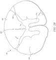
- Figure 2A is a partially schematic cross-sectional illustration of a patient's spinal cord 191 showing relative locations of laminae I-X within the spinal cord.
- delivering a therapeutic electrical signal to inhibit at least a portion of the patient's sympathetic nervous system, such as a sympathetic nerve can treat the patient's blood glucose abnormality.
- the therapeutic electrical signal is delivered to the portion of the patient's sympathetic nerves by an implanted signal delivery device, such as those described herein.
- the inhibitory effects of the therapeutic electrical signal can modulate the patient's sympathetic interneurons, which are GABAergic and elicit monosynaptic inhibitory post synaptic potentials in sympathetic preganglionic neurons (SPNs) within the intermediolateral cell column.
- Sympathetic interneurons are generally located in laminae V, VII, and X of the patient's spinal cord and less often in superficial laminae I - IV.
- lamina V-X and in particular lamina X may be associated with sympathetic modulation by mediating any inhibitory effects of the therapeutic modulation signal on one or more of the patient's sympathetic nerves.
- the therapeutic electrical signal is directed to lamina X of the patient's spinal cord to inhibit the patient's sympathetic system, such as via the sympathetic interneurons.
- Figure 2B is a histological image of a rat thoracic spinal cord.
- the dorsal median sulcus 250 separates the patient's left dorsal column 255 and right dorsal column 257.
- the dorsal median sulcus 250 contains cerebral spinal fluid, which is about five times more conductive than the white or gray matter of the patient's spinal column.
- the therapeutic electrical signal may reach lamina X of the patient's spinal cord (1) via conduction of the patient's cerebral spinal fluid at the patient's dorsal median sulcus, (2) via one or more of laminae I-IX, (3) via another mechanism, or (4) a combination of any of (1)-(3).
- the dorsal horn 260 and the ventral horn 270 are shown for purposes of orientation.
- Figure 3 is a partially schematic illustration of a patient's sympathetic nervous system 310 and parasympathetic nervous system 350, and the organs innervated by the corresponding sympathetic nerves 315 and/or the parasympathetic nerves 355.
- a lead body 111 (shown prior to implant in Figure 3 ) can be positioned at or proximate to the thoracic region 320 (e.g., T1-T12) of the patient's spinal column 330.
- Applying a therapeutic modulation signal to a target location at or between T2 to T12 of the patient's thoracic region may modulate one or more of the patient's sympathetic nerves 315, such as the celiac ganglia 342, the superior mesenteric ganglia 344, and the inferior mesenteric ganglia 348.
- the modulation inhibits one or more of the sympathetic nerves 315 innervating the patient's liver 361, pancreas 365, adrenal gland 367, and/or stomach 363.
- glucose uptake by the patient's liver 361 may increase, which lowers the patient's post-prandial blood glucose levels, thereby treating the patient's T2D.
- Figure 4A is a partially schematic illustration of a patient's spinal cord 191 and an enlarged illustration of the patient's liver 400, illustrating sympathetic nerves innervating the liver 400.
- the sympathetic chain ganglion 402 is shown for reference.
- Nerves which innervate the liver extend from the left greater thoracic splanchnic nerve 405, the anterior vagal trunk 410, the right phrenic nerve 420, the posterior vagal trunk 430, and the right greater thoracic splanchnic nerve 440.
- the anterior hepatic plexus 460, the posterior hepatic plexus 465, and the phrenic ganglion 470 also extend into the liver 400.
- the celiac ganglion 450 is also shown for reference.
- Delivering the therapeutic signals of the present technology can exert a therapeutic benefit upon the liver 400.
- the therapeutic signals will decrease the sympathetic tone innervating the liver, which will increase post-prandial uptake of glucose in the liver that is stored as glycogen.
- the therapeutic signals exert these benefits by affecting metabolism of insulin, glucagon, GLP-1, and/or the adrenal hormone.
- the therapeutic signals can also directly affect the patient's liver 400, such as by inducing one or more effects of insulin, glucagon, GLP-1, and/or the adrenal hormone on the patient's liver 400.
- the therapeutic signals can affect a ratio of insulin and glucagon, and these ratios may be pathologic in a patient having T2D.
- the ratio of insulin to glucagon may be too high in a hyperinsulinemic T2D patient.
- therapeutic signals can lower a patient's need for insulin which can induce release of glucagon from the patient's liver 400, such as by reducing insulin levels.
- FIG 4B is a partially schematic cross-sectional illustration of a patient's spinal cord 410, and an enlarged illustration of the patient's adrenal medulla 420.
- the adrenal medulla 420 is directly innervated by sympathetic preganglionic neurons (SPNs) 430.
- SPNs 430 promote release of catecholamines (dotted arrow) which are associated with increased blood glucose levels, by promoting glucose release from the patient's liver.
- Delivering one or more therapeutic modulation signals to one or more of the patient's sympathetic interneurons in lamina X can directly and/or indirectly inhibit SPN activity which can indirectly affect glucose metabolism in the patient's liver, e.g., as described above with reference to Figure 4A .
- Figure 5 is a partially schematic illustration of a portion of a patient's renal system.
- Figure 5 shows the patient's adrenal glands 367a and 367b, each of which includes an adrenal cortex 368 and an adrenal medulla 369.
- the patient's left adrenal gland 367a is proximally located from the patient's right adrenal gland 367b.
- the implantable stimulation devices e.g., leads 111
- the implantable stimulation devices can be placed at different levels relative to the patient's spinal column and in some cases, on opposite sides of the patient's spinal column.
- a first lead can be positioned proximate to and on the right side of the patient's T10 vertebra whereas, to inhibit the sympathetic nerves innervating the right adrenal gland 367b, a second lead can be positioned proximate to and on the left side of the patient's T9 vertebra.
- the first lead can be positioned proximate to and on the left side of the patient's T10 vertebra and the second lead can be positioned proximate to and on the right side of the patient's T9 vertebra.
- the vertebral locations are not limited to T9 and T10 and can also include any number of thoracic vertebrae from T2 to T12.
- Figure 6 is an image of a patient's spine 600 along with two percutaneous signal delivery devices 111 (shown as signal delivery devices 111f and1 11g) implanted at representative locations.
- signal delivery devices 111f and1 11g are shown in Figure 6 implanted in the same patient.
- any given patient may receive more or less than the two signal delivery devices 111g and 111f shown in Figure 6 .
- a first signal delivery device 111f having a first plurality of contacts C is positioned on a first side 610 of a midline M of the patient's spinal column 600 and a second implantable signal delivery device 111g having a second plurality of contacts C is positioned on a second side 620 of the midline M.
- the first plurality of contacts C are positioned longitudinally along the first side 610 of the midline M, from T8 to T10, and the second plurality of contacts are positioned longitudinally along the second side 620 of the midline M, from T9 to T11.
- the first implantable signal delivery device 111f and the second implantable signal delivery device 111g can be positioned on the same side of the midline M (e.g., either the first side 610 or the second side 620).
- the first plurality of contacts C can be positioned longitudinally along the first side 610 of the midline M, from T7 to T10, and the second plurality of contacts are positioned longitudinally along the second side 620 of the midline M, from T5 to T8.
- the vertebral ranges in which the first plurality of contacts C and the second plurality of contacts C can differ from those disclosed herein.
- the first implantable signal delivery device 111f and the second implantable signal delivery device 111g are shown overlapping by about 1/2 to about 1/3 of a length of each of the signal delivery devices. However, in representative systems and methods the first implantable signal delivery device 111f and the second implantable signal delivery device 111g do not overlap.
- the second implantable signal delivery device 111g can be positioned at least generally end to end such that the first plurality of contacts C and the second plurality of contacts C extend generally longitudinally along the midline M.
- the first implantable signal delivery device 111f can also be positioned to span a first portion 613 of the patient's tissue on a first side 610 of the midline M and a first portion 623 of the patient's tissue on a second side 620 of the midline M.
- the second implantable signal delivery device 111g can be positioned to span a second portion 617 of the patient's tissue on the first side 610 of the midline and a second portion 627 of the patient's tissue on the second side 620 of the midline M.
- At least one contact C of the first plurality of contacts is positioned proximate to the first portion 613 of the first side 610 and at least one contact C of the first plurality of contacts is positioned proximate to the first portion 623 of the second side 620.
- at least one contact C of the second plurality of contacts is positioned proximate to the second portion 617 of the first side 610 and at least one contact C of the second plurality of contacts is positioned proximate to the second portion 627 of the second side 620.
- the therapeutic electrical stimulation signals can be delivered to a target location.
- the target location can also include a first target portion and a second target portion.
- the first implanted signal delivery device 111f can be positioned proximate to the first target portion 623 and/or the second implanted signal delivery device 111g can be positioned proximate to the second target portion 627.
- the first target portion is proximate to a first thoracic vertebrae and the second target portion is proximate to a second thoracic vertebrae that can be the same or different from the first thoracic vertebrae.
- the therapeutic modulation signal can be delivered to the patient's target location at generally the same time (e.g., simultaneously or approximately simultaneously) via one or more implantable therapeutic signal delivery devices.
- inhibiting the sympathetic nerves to treat the blood glucose abnormality may be achieved following delivery of one or more therapeutic modulation signals having one or more stimulation parameters at or proximate to one or more of T2 to T12 vertebrae, e.g., T9 and/or T10.
- the stimulation parameters include, but are not limited to, amplitude, frequency, pulse width, duty cycling, and whether stimulation is applied at or proximate to the patient's left side or the patient's right side of their midline.
- the therapeutic modulation signal has an amplitude from about 20% to about 90% of the patient's sensory threshold, a frequency of about 10 kHz, and a pulse width of about 30 microseconds, but representative systems and methods can have any one of the amplitudes, frequencies and/or pulse widths disclosed throughout this disclosure and particularly under Headings 3.0 and 4.0.
- the therapeutic modulation signal can be delivered to the patient pre-prandially, prandially, and/or post-prandially and in representative systems and methods, one or more stimulation parameters of the therapeutic modulation signal can differ between a pre-prandial therapeutic modulation signal, prandial therapeutic modulation signal, and/or post-prandial therapeutic modulation signal.
- prandial refers to the duration of time when the patient is consuming calories
- the prandial time period can, in accordance with representative systems and methods, range from about 30 minutes to about 120 minutes.
- one or more therapeutic modulation signals can be delivered to a target location proximate to at one or more vertebral levels in the range of C8-T12, T2-T12, T4-T10, or T4 to T6.
- the therapeutic modulation signals may inhibit at least a portion of the patient's celiac ganglion associated with sympathetic nerves that innervate the patient's stomach, liver, pancreas, and/or adrenal glands.
- Inhibiting the patient's sympathetic nerves associated with one or more of the target locations at or proximate to T4 to T6 can be achieved by positioning one or more implantable therapeutic signal delivery devices at or proximate to one or more of T4 to T6.
- Inhibiting one or more of the patient's sympathetic nerves can promote glucose uptake in the patient's liver and/or lower the patient's post-prandial blood glucose levels.
- one or more therapeutic modulation signals can be delivered to a target location proximate to or at one or more of T7 to T12.
- These therapeutic modulation signals may inhibit at least a portion of the patient's celiac ganglion and/or superior mesenteric ganglia, associated with sympathetic nerves that innervate the patient's small and large intestine, as well as the patient's stomach, duodenum, jejunum, and ileum.
- Inhibiting the patient's sympathetic nerves associated with one or more of T7 to T12 can be achieved by positioning at least one (e.g., at least two in some cases) implantable therapeutic signal delivery devices at or proximate to one or more of T7 to T12.
- inhibiting one or more of the patient's sympathetic nerves can increase incretin release from the patient's intestine and/or ghrelin release from the patient's stomach.
- slow waves e.g., rhythmic electrophysiological events
- the duty cycle of the therapeutic modulation signal such as by altering one or more of the on cycle portion of the duty cycle and/or the off cycle portion of the duty cycle.
- the therapeutic signal is delivered to patients continuously or intermittently, such as at various times throughout the day.
- the therapeutic signal can be coordinated to be pre-prandial, prandial, and post-prandial.
- the therapeutic signal can be delivered while the patient is prandial and, by doing so, increase the uptake of glucose by the patient's liver, compared to prandial patients not receiving the therapeutic signal.
- the duration of prandial time can be from about 30 minutes to about 120 minutes, and can differ within a single day or it can be generally the same.
- the therapeutic signal can be delivered at an amplitude having an amplitude range of between about 20% to about 90% of the patient's sensory threshold, at a frequency of about 10 kHz, and/or about a 30 microsecond pulse width.
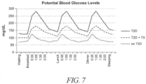
- Figure 7 illustrates expected blood glucose levels of (1) a patient who has T2D and is not receiving any therapeutic modulation signals, (2) a patient who has T2D and is receiving one or more therapeutic modulation signals described herein (e.g., electrical stimulation therapy), and (3) a patient who does not have T2D.
- each patient's blood glucose levels rise from pre-prandial levels while the patient is prandial (e.g., eating breakfast, lunch, and/or dinner) and fall while the patient is post-prandial (e.g., after the patient has stopped eating).
- the electrical stimulation therapy is delivered intermittently to treat the patient's T2D, such as intermittently during one or more of the pre-prandial, peri-prandial (e.g. at or near the prandial phase), prandial, post-prandial, and sleeping phases.
- delivering one or more of the therapeutic modulation signals described herein to a patient having T2D can decrease the T2D patient's pre-prandial, prandial, and post-prandial blood glucose levels compared to the T2D patient not receiving the therapy.
- the electrical signal is delivered during the peri-prandial phase and the prandial phase can be the same as the therapy delivered during a non-prandial phase (e.g., pre-prandial, post-prandial, and/or sleeping phase).
- the electrical signal delivered during the peri-prandial phase and/or the prandial phase can include 2 to 5 bipoles, such as 3 to 4 bipoles and the therapy delivered during non-prandial phases can include one or more pulses.
- stimulating multiple bipoles simultaneously at multiple spinal levels can provide a broader sympathetic inhibition to various organs involved in diabetes, including the liver, stomach, pancreas, adrenals, and intestines.
- the electrical signal delivered during the sleeping phase can also differ from the electrical signal delivered during other phases.
- certain electrical signals can avoid certain phenomenon effects in some patients, e.g., Somogyi effects and dawn phenomenon effects. These effects can involve hypoglycemic or near hypoglycemic events between about 1:00am and 4:00am, such as between about 2:00am and about 3:00am, that initiate a hyperglycemic sympathetic response once the patient wakes, e.g., in the morning.
- electrical signals delivered during the sleeping phase include an off period between about 1:00am and about 4:00am to prevent the hyperglycemic sympathetic response from occurring.
- the therapeutic modulation signals can be generally synchronized for delivery when the patient is prandial and for a duration of time while the patient is post-prandial.
- the T2D patient can receive one or more therapeutic modulation signals when his/her prandial phase begins, and the one or more therapeutic modulation signals can be continuously or intermittently delivered to the T2D patient for about 30 minutes to about 120 minutes during the prandial phase and/or extending into the post-prandial phase.
- Delivering one or more therapeutic modulation signals described herein to a patient having T2D can maintain the T2D patient's blood glucose levels between about 75 mg/dL and about 200 mg/dL, and more specifically, between about 100 mg/dL and about 175 mg/dL.
- the therapeutic modulation signal(s) can reduce the T2D patient's blood glucose level by at least about 10%, at least about 15%, at least about 20%, at least about 25%, at least about 30%, at least about 35%, at least about 40%, at least about 45%, or at least about 50% following delivery of the therapeutic modulation signal (e.g., electrical therapy signal).
- the therapeutic modulation signal e.g., electrical therapy signal
- the T2D patient's HbA1c levels can also be altered following delivery of or more therapeutic modulation signals.
- the T2D patient's HbA1c level is reduced by at least about 1%, at least about 1.5%, at least about 2%, at least about 2.5%, at least about 3%, at least about 3.5%, at least about 4%, at least about 4.5%, at least about 5%, at least about 6%, at least about 7%, at least about 8%, at least about 9%, or at least about 10% following delivery of the electrical signal.
- While representative systems and methods of the present technology may create some effect on normal motor and/or sensory signals, the effect is below a level that the patient can reliably detect intrinsically, e.g., without the aid of external assistance via instruments or other devices. Accordingly, the patient's levels of motor signaling and other sensory signaling (other than signaling associated with T2D) can be maintained at pre-treatment levels. For example, the patient can experience a significant reduction in T2D, HbA1c levels, and/or one or more associated symptoms, largely independent of the patient's movement and position.
- the patient can assume a variety of positions, consume various amounts of food and liquid, and/or undertake a variety of movements associated with activities of daily living and/or other activities, without the need to adjust the parameters in accordance with which the therapy is applied to the patient (e.g., the signal amplitude).
- This result can greatly simplify the patient's life and reduce the effort required by the patient to undergo T2D treatment (or treatment for corresponding symptoms) while engaging in a variety of activities.
- This result can also provide an improved lifestyle for patients who experience symptoms associated with T2D during sleep.
- patients can choose from a number of signal delivery programs (e.g., two, three, four, five, or six), each with a different amplitude and/or other signal delivery parameter, to treat the patient's blood glucose abnormality.
- the patient can activate one program before sleeping and another after waking, or the patient can activate one program before sleeping, a second program after waking, and a third program before engaging in particular activities that would otherwise trigger, enhance, or otherwise exacerbate the patient's blood glucose abnormality, such as pre-prandial, prandial, and/or post-prandial activities.
- the patient can activate a fourth program when the patient is pre-prandial, a fifth program when the patient is prandial, and/or a sixth program when the patient is post-prandial.
- the fourth program and/or the sixth program can be the same, and can also be generally the same as the programs activated before sleeping and/or after waking.
- This reduced set of patient options can greatly simplify the patient's ability to easily manage the blood glucose abnormality, without reducing (and in fact, increasing) the circumstances under which the therapy effectively addresses the blood glucose abnormality.
- the patient's workload can be further reduced by automatically detecting a change in patient circumstance, and automatically identifying and delivering the appropriate therapy regimen. Additional details of such techniques and associated systems are disclosed in U.S. Patent No. 8,355,797 .
- the systems, devices, and methods described herein automatically detect a beginning and/or an end of one or more prandial events.
- the systems, devices, and methods described herein can automatically detect one or more prandial events by monitoring the patient's blood glucose levels, either intermittently or continuously and if a change in the patient's blood glucose level is detected, the systems, devices, and methods described herein can automatically deliver therapeutic electrical signals.
- Representative systems and methods described herein can include one or more sensors configured to monitor the patient's blood glucose levels by detecting an amount of glucose in the patient's blood.
- electrical stimulation may be administered on a pre-determined schedule or on an as-needed basis. Administration may continue for a pre-determined amount of time, or it may continue indefinitely until a specific therapeutic benchmark is reached, for example until an acceptable reduction in one or more symptoms is obtained.
- electrical stimulation may be administered one or more times per day, one or more times per week, once a week, once a month, or once every several months. Since electrical stimulation is thought to improve the patient's blood glucose abnormality (e.g., normalize the patient's blood glucose levels) over time with repeated use of therapeutic electrical signals, the patient may need less frequent electrical signal therapy. In representative systems and methods, the therapy can be delivered when the patient's blood glucose abnormality recurs or increases in severity.
- Administration frequency may also change over the course of treatment. For example, a patient may receive less frequent administrations over the course of treatment as certain therapeutic benchmarks are met.
- the duration of each administration e.g., the actual time during which a subject is receiving electrical stimulation
- a therapeutic modulation signal in accordance with representative systems and methods can have an amplitude in an amplitude range of between about 20% to about 90% of the patient's sensory threshold, at a frequency of about 10 kHz, and/or about a 30 microsecond pulse width and can be applied at a particular vertebral level associated with the organ of interest, such as at the thoracic vertebral levels (e.g., T2-T12) to inhibit activity of the patient's sympathetic nervous system (e.g., the sympathetic nerves innervating) or otherwise associated with the patient's stomach, liver, pancreas, one or more adrenal glands, duodenum, jejunum, ileum, and large intestine.
- the sympathetic nervous system e.g., the sympathetic nerves innervating
- therapeutic electrical stimulation to treat a patient's blood glucose abnormality is performed with at least a portion of the therapy signal at a frequency in a frequency range between about 1.2 kHz and about 100 kHz; between about 1.5 kHz and about 100 kHz, between about 1.5 kHz and about 50 kHz; between about 3 kHz and about 20 kHz; between about 3 kHz and about 15 kHz; or between about 5 kHz and about 15 kHz; or at frequencies of about 5 kHz, about 6 kHz, about 7 kHz, about 8 kHz, about 9 kHz, about 10 kHz, about 11 kHz, about 12 kHz, about 10 kHz, about 25 kHz, or about 50 kHz.
- therapeutic electrical stimulation to treat a patient's blood glucose abnormality is performed with at least a portion of the therapy signal at amplitudes within amplitude ranges of: about 0.1 mA to about 20 mA; about 0.5 mA to about 10 mA; about 0.5 mA to about 7 mA; about 0.5 mA to about 5 mA; about 0.5 mA to about 4 mA; and/or about 0.5 mA to about 2.5 mA.
- therapeutic electrical stimulation to treat a patient's blood glucose abnormality is performed with at least a portion of the therapy signal having a pulse width in a pulse width range of from about 1 microsecond or less to about 416 microseconds, from about 10 microseconds to about 333 microseconds; from about 10 microseconds to about 166 microseconds; from about 25 microseconds to about 166 microseconds; from about 25 microseconds to about 100 microseconds; from about 30 microseconds to about 100 microseconds; from about 33 microseconds to about 100 microseconds; from about 30 microseconds to about 40 microseconds, and/or from about 50 microseconds to about 166 microseconds.
- therapeutic electrical stimulation to treat a patient's blood glucose abnormality is performed with at least a portion of the therapy signal having a 30 microsecond cathodic pulse followed by a 20 microsecond interphase delay followed by a 30 microsecond anodic pulse followed by another 20 microsecond interphase delay.
- the total phase time duration of 100 microseconds corresponds to a frequency of 10 kHz.
- the total phase time duration may range from 10 - 833 microseconds corresponding to frequencies ranging from 1200 Hz - 100 kHz.
- the interphase delays may differ from 20 microseconds and may range from 0 to the maximum difference between the phase time duration and the combined pulse widths of an anodic and cathodic pulse (for a bi-phasic waveform).
- the cathodic and/or anodic pulses may differ from 30 microseconds and may range from one microsecond or less to the maximum difference between the phase time duration and the duration of an interphase delay (for a bi-phasic waveform).
- the opposing phases of a given pulse pair may not be symmetric (e.g., may have different widths and/or amplitudes), but generally provide the same magnitude of charge, though at opposite polarities, to provide charge balancing on a pulse-by-pulse basis.
- aspects of the therapy provided to the patient may be varied, while still obtaining beneficial results.
- the location of the lead body (and in particular, the lead body electrodes or contacts) can be varied throughout and/or across the target location(s) described above, such as target locations proximate to or at T2 to T12, and/or other organs, tissues, and/or neurological structures.
- Other characteristics of the applied signal can also be varied.
- the amplitude of the applied signal can be ramped up and/or down and/or the amplitude can be increased or set at an initial level to establish a therapeutic effect, and then reduced to a lower level to save power without forsaking efficacy, as is disclosed in U.S. Patent Publication No. 2009/0204173 .
- the signal amplitude may refer to the electrical current level, e.g., for current-controlled systems or to the electrical voltage level, e.g., for voltage-controlled systems.
- the specific values selected for the foregoing parameters may vary from patient to patient and/or from indication to indication and/or on the basis of the selected electrical stimulation location.
- the present technology may make use of other parameters, in addition to or in lieu of those described above, to monitor and/or control patient therapy.
- the pulse generator includes a constant voltage arrangement rather than a constant current arrangement
- the current values described above may be replaced with corresponding voltage values.
- the parameters in accordance with which the pulse generator provides signals can be modulated during portions of the therapy regimen.
- the frequency, amplitude, pulse width and/or signal delivery location can be modulated in accordance with a preset program, patient and/or physician inputs, and/or in a random or pseudorandom manner.
- Such parameter variations can be used to address a number of potential clinical situations, including changes in the patient's perception of one or more symptoms associated with the condition being treated, changes in the preferred target neural population, and/or patient accommodation or habituation.
- a practitioner can obtain feedback from the patient to detect the patient's blood glucose levels and/or the effect of the therapeutic modulation signal on the patient's blood glucose abnormality.
- Monitoring a patient's blood glucose level can be performed on a continuous basis using one or more sensing elements (referred to herein as a "sensing element") for detecting neural signals, neural responses, and/or other physiological parameters of the patient before, during and/or after the application of electrical stimulation signals to the patient.
- the sensing element can be carried by the signal generator 101, the signal delivery elements 110, and/or other implanted components of the system 100, as previously described with reference to FIG. 1A .
- the sensing element may be positionable in an area proximate to the target treatment site where electrical stimulation is being delivered.
- the sensing element can be positioned separate from the signal generator 101 and/or the signal delivery elements 104.
- the sensing elements may be implanted in an area separate from the area where electrical stimulation is being delivered, or in an extracorporeal manner.
- the sensing element and the signal generator 101 may be coupled to one another via a wired link or a wireless link (e.g., via a Bluetooth link).
- sensing elements can include an impedance sensor, a chemical sensor, a biosensor, an electrochemical sensor, a hemodynamic sensor, an optical sensor and/or other suitable implantable sensing devices.
- the sensing element can be a cuff electrode, and can be positioned around a nerve (e.g., the vagus nerve or the splanchnic nerve) or proximate to a target neural population of the patient.
- the sensing element detects one or more neural signal(s) and/or neural response(s) (e.g., electrical signals corresponding to action potentials) from the nerve or neural population, and the system (e.g., the system 100 referenced in FIG.
- the 1A uses the detected neural signal(s) and/or neural response(s) to identify the patient's blood glucose level at a particular moment in time.
- the neural response(s) can be detected frequently enough such that an upward or downward trend of the data corresponding to the blood glucose levels can be determined, or at least estimated.
- the detected neural response(s) may be associated with the electrical signal that is, for example, generated subsequent to receptors of the neural population binding to glucagon.
- the detected neural signal(s) and/or response(s) can include characteristics that may be measured and used to identify the patient's blood glucose levels at a particular point in time. Characteristics can include, for example, signal strength (e.g., whether a value of the signal is above a pre-determined threshold value), frequency (e.g., number of action potentials fired in a given time), amplitude and/or velocity, amongst other measurable characteristics. In representative systems and methods, changes of a characteristic from one or more previous neural signals or neural responses, and/or rates of change of a characteristic from previous neural signals or neural responses, can be used in a similar manner. Measurements associated with the characteristics can then be used to identify blood glucose levels at a particular moment in time.
- the identified blood glucose levels may be determined or estimated based on a pre-determined correlation between the values of the characteristics of the neural response(s) and the blood glucose levels of the patient or a similarly-situated patient.
- the correlation may be developed by, for example, controlling a particular glucose concentration of the patient and monitoring neural responses of the patient at that concentration. This process can be repeated for multiple concentrations until a correlation is developed over a range of concentrations.
- an advantage of representative systems and methods of the present monitoring technology over conventional or traditional detection methods/devices is that they do not rely on consumable materials that deplete over time.
- the implantable sensing element of the present technology can determine the patient's blood glucose levels based on characteristics of an electrical signal (i.e., the neural responses of the patient) and thus does not need to be removed and replaced, or at least not as often as devices in accordance with conventional technologies.
- Yet another advantage of representative systems and methods of the present monitoring technology over conventional or traditional detection methods/devices is that the accuracy of the present technology does not generally degrade over time. This is unlike conventional devices that include substances and can be used multiple times. Such devices can have issues with accuracy as the devices approach the end of their lifespan.
- Monitoring the patient's blood glucose levels can be performed in tandem with modulating electrical therapy signals to the patient. Stated otherwise, the patient's blood glucose levels can be continuously (or periodically) monitored using the methods described herein, and used to determine or adjust the signal delivery parameters so as to improve the effect of the modulated electrical therapy signals.
- the practitioner can (a) continuously observe/monitor the patient's blood glucose levels to determine a baseline level, (b) direct an electrical therapy signal (e.g., a signal having a frequency from 1.2 kHz to 100 kHz) to a neural population of the patient via an implantable signal delivery device, (c) monitor the patient's blood glucose levels after directing the therapy signal to report changes in diabetic response (e.g., glucose levels, amount of insulin needed, etc.) and/or other functions, and (d) if necessary, adjust the electrical therapy signal to achieve a more desirable blood glucose level.
- an electrical therapy signal e.g., a signal having a frequency from 1.2 kHz to 100 kHz
- Adjusting the electrical therapy signal can include adjusting one or more signal delivery parameters (e.g., frequency, amplitude, pulse width, duty cycle, and normal slow wave frequency) of the subsequent electrical signal to be applied to the target location. Steps (a)-(d) can be performed iteratively to improve or achieve a desired result for the patient. Suitable methods and products for monitoring this system include those where the patient's response to the electrical stimulation therapy can be adjusted.
- the patient's response can include one or more measurements of the patient's serum glucose levels, such as an oral glucose tolerance test, fasting blood glucose levels, and HbA1c percentages.
- the continuous monitoring methods of the present technology can also be used for applications other than glucose monitoring and T2D.
- the monitoring methods can be used to monitor other chemicals (e.g., dopamine, serotonin, etc.) based on neural responses of the patient, and to treat other diseases of disorders (e.g., depression, Parkinson's, etc.).
- the monitoring methods of the present technology can be used as a diagnostic tool to pre-emptively monitor diseases.
- the implantable sensing device can be implanted prior to an onset of any particular disease (e.g., T2D), and data from the sensing device can be used to identify trends that may be used to suggest the onset of the disease.
- Data from the sensing device can be wirelessly transmitted (e.g., to a server) such that the practitioner can remotely monitor the data and identify trends.
- FIG. 8 is a schematic block diagram illustrating a process 800 for delivering therapy based on feedback from the patient, in accordance with representative systems and methods of the present technology.
- This approach can be used with any of the signal delivery modalities described herein (e.g., signal delivered via one signal device or more than one, signals delivered to one target neural population or more than one).
- Block 802 includes establishing the signal delivery parameters, including the signal delivery schedule.
- block 802 can include establishing a continuous therapy regimen, in which the patient receives a therapy signal 24 hours a day, 7 days a week.
- the therapy signal may be delivered in accordance with a duty cycle.
- the therapy signal may be delivered in accordance with a schedule that is tied to the patient's eating behavior.
- the patient can receive therapy for one hour before and after a meal, as well as during the meal.
- the patient can activate the therapy manually, or, for example, if the patient is on a more or less fixed schedule, the therapy can automatically be activated via a timer so as to be delivered before, during and after the meal.
- the foregoing time periods can be adjusted (e.g., to be other than one hour before and/or one hour after), and/or one or two of the time periods can be eliminated.
- the additional signal delivery parameters include signal frequency, amplitude, pulse width, and other waveform parameters, e.g., interpulse interval or interphase interval.
- the signal delivery parameters can further include which, among multiple possible electrodes or contacts, are activated at any particular time.
- the therapy is delivered, in accordance with the signal delivery schedule and other parameters described above.
- the effects of the therapy on the patient are detected.
- block 806 can include detecting a serum blood glucose level, at a particular point in time.
- detecting the effects of the therapy can include obtaining longer term measurements.
- an A1C measurement is typically an average of A1C protein levels taken over a longer period of time, for example, three to four months.
- a 5% A1C level is considered normal, and levels above 6% trigger an evaluation, as described below.
- Representative systems and methods can include detecting or measuring other parameters, in addition to or in lieu of blood glucose - for example, insulin levels and/or blood pressure.
- the measured effects are then used to determine: whether the therapy is to be continued (block 807) and whether the therapy can be improved (block 808). If the therapy is to be discontinued (e.g., if the measured effects include an unsafe or otherwise undesirable effect), the therapy is halted at block 809. If not, then if the therapy can be improved (e.g., optimized), block 810 includes establishing updates for the therapy, and the process returns to block 804 to continue delivering therapy in accordance with the updated parameters. If, at block 808, the therapy is determined to be optimized (or is otherwise not to be changed), then the process returns to block 804 without establishing the updates identified at block 810.
- the process 800 described above can be carried out in an automated fashion, or with a "person in the loop." For example, a practitioner can determine whether the therapy can be improved at block 808, and can establish the updates at block 810 if the therapy can be improved. In other representative methods, the process can be more automated.
- the patient can use a constant glucose monitor that continuously monitors the patient's blood glucose level and communicates the measurements to an internal or external processor (e.g., an implanted pulse generator, or a phone-based app or other external device).
- an internal or external processor e.g., an implanted pulse generator, or a phone-based app or other external device.
- the system can use Bluetooth or another suitable wireless communication protocol.
- the system can automatically determine whether or not to change the signal parameters at block 808, and can automatically establish proposed updates at block 810.
- the updates can be based on historical data for the particular patient, and/or historical data for a larger patient population having the same or similar indications.
- the frequency of the signal can determine the effect of the signal on the patient's physiology. For example, some frequencies may affect the patient's production of insulin, and others may affect the patient's storage of glucose. Generally, high frequency signals (e.g., above about 1200 Hz) can have an inhibitory effect, while lower frequency signals can have an excitatory effect. The effects may be limited to the specific neural populations to which the signals are directed. Accordingly, if the neural population is inhibitory (e.g., an inhibitory interneuron), an excitatory effect on an inhibitory neural population can produce an overall inhibitory physiological effect on the patient.
- inhibitory e.g., an inhibitory interneuron
- the disclosed techniques can affect both insulin levels and the patient's glucose storage rates. By controlling both variables, these techniques can more accurately control the patient's blood sugar levels, and therefore more accurately control the patient's T2D.
- This approach can provide significant advantages over existing techniques for addressing T2D. For example, current techniques include administering insulin to the patent to reduce blood sugar levels. While this approach can have an acute benefit of reducing blood sugar levels, over the long term, it may actually worsen the patient's disease state.
- the assignee of the present application has conducted clinical studies with patient's suffering from painful diabetic neuropathy (PDN).
- PDN painful diabetic neuropathy
- the primary purpose of the studies is to obtain data regarding the ability of electrical stimulation therapies to address the pain experienced by PDN patients.
- preliminary results of the study appear to suggest that, in addition to addressing PDN, the electrical stimulation therapy may be effective for addressing T2D.
- 20% of patient's receiving electrical stimulation therapy in accordance with the foregoing parameters reported a significant reduction in A1C levels (e.g., in a range of 15%-23% reduction) over the course of three months of treatment.
- Patients who did not receive the electrical stimulation during the study did not indicate an A1C reduction.
- the patient's received a 10 kHz signal, with 30 microsecond anodic/cathodic biphasic pulses.
- the therapy was delivered from electrodes located at the T9-T1 0 vertebra level.
- A1C reduction is achievable via electrical stimulation having frequencies in the ranges disclosed herein, and that tailoring the therapy delivery parameters more specifically to A1C reduction (rather than pain reduction) may further improve the results.
- the therapy in the clinical study described above was delivered via electrodes at vertebral levels of approximately T9-T10 to address the patient's pain, while therapy directed to these locations reduced A1C levels, further reduction may be achieved at more cephalad vertebral levels (e.g., T4-T6) to provide better results for T2D patients.
- electrical stimulation may be applied directly to the T2-T12 region, an organ, and/or another target tissue, or it may be applied in close proximity to the T2-T12 region, an organ, and/or another target tissue (i.e., close enough for neurons at the T2-T12 region, an organ, and/or another target tissue to receive the electrical signal).
- electrical stimulation can be applied at or proximate to a target location in the T2-T12 region.
- the electrical stimulation can be applied to other neural tissue such as peripheral nerves corresponding to the T2-T12 region (e.g., sympathetic nerves).
- electrical stimulation can be applied to the vagal nerve, such as the hepatic branch of the vagus nerve. Stimulation at the hepatic branch may increase activity of glycogen synthase, an enzyme involved in glucose metabolism, such as the conversion of glucose into glycogen.
- electrical stimulation may be applied to a single target tissue or organ.
- electrical stimulation may be applied to the T2-T12 region, multiple organs, and/or multiple other target tissues.
- stimulation may be applied to the T9 and/or T10 region, a nerve and/or a target tissue corresponding to T9 and/or T10, an organ corresponding to T9 and/or T10, or a combination thereof.
- electrical stimulation parameters may be configured so as to not result in the patient experiencing paresthesia.
- the therapeutic modulation signal can operate on the targeted organ or organs in accordance with any of a number of mechanisms.
- the therapeutic modulation signal can have an effect on a network of neurons, rather than an effect on a particular neuron.
- This network effect can in turn operate to reduce and/or otherwise inhibit one or more effects of the sympathetic nervous system described above.
- the foregoing mechanisms of action can have a cascading effect on other systems.
- the effect of inhibiting the sympathetic nervous system can be indirect. As a result of this indirect effect, the ultimate effect on the organ may not occur instantaneously, but rather may take time (e.g., days) to develop, in response to a modulation signal that is applied to the patient for over a similar period of time (e.g., days).
- Suitable devices for administering an electrical signal to the T2-T12 region, an organ, and/or another target tissue are described in greater detail above under Heading 3.0 and may also be described in the references incorporated by reference herein.
- Examples of devices for administering an electrical signal that can treat T2D, reduce HbA1c levels, and/or treat pain are disclosed in U.S. Patent Nos. 8,694,108 and 8,355,797 .
- applying electrical stimulation can be carried out using suitable devices and programming modules specifically programmed to carry out any of the methods described herein.
- the device can comprise a lead, wherein the lead in turn comprises an electrode.
- administering electrical stimulation comprises a positioning step (e.g., placing the lead such that an electrode is in proximity to the sacral region, an organ, and/or another target tissue) and a stimulation step (e.g., transmitting an electrical signal to the electrode).
- a device that is used for applying an electrical signal to the spinal cord may be repurposed with or without modifications to administer an electrical signal to another target tissue or organ, e.g., at the T2-T12 region, a cortical, sub-cortical, intra-cortical, or peripheral target.
- target tissues or organs include the hypothalamus, brainstem, the limbic system, the cerebral cortex, the vagus nerve, and other direct end organs.
- any of the herein described systems, sub-systems, and/or sub-components serve as means for performing any of the herein described methods.
- T2D represents an example indication that can be treated with modulation applied at this location.
- modulation signals having parameters e.g., frequency, pulse width, amplitude, and/or duty cycle
- parameters e.g., frequency, pulse width, amplitude, and/or duty cycle
- a representative method includes treating a patient's blood glucose abnormality by applying an electrical signal to the patient's T2-T12 region, with the electrical signal having parameters as disclosed throughout the present application, for example, a frequency in a range of from about 1.2 kHz to about 100 kHz, a pulse width in a pulse width range of one microsecond or less to 416 microseconds, and an amplitude in an amplitude range of 0.1 mA to 20 mA .
- the duty cycle (when less than 100%), can be between 5% and 75%, for example 60%-75%, 40%-60% (e.g., 50%), 25%-50%, or 10%-20%.
- a representative method includes programming a device (or instructing programming of a device) to deliver electrical stimulation therapy in accordance with any of the foregoing parameters. Accordingly, any and all methods of use and manufacture disclosed herein also fully disclose and enable corresponding methods of instructing such methods of use and manufacture.
- signals having the foregoing characteristics can provide therapeutic benefits for patients having T2D, when stimulation is applied at T9 and/or T10.
- the electrical signal can have a more significant and/or targeted effect, e.g., when the electrical signal is directed to specific neurons or neural populations associated with specific organs that are enervated by nerves exiting the spinal cord at vertebral levels from about T2 to about T12, as described above.
- the present technology can be used to address one or more pain indications, besides and/or in addition to T2D.
- the methods, systems, and devices described above may, in addition to treating the blood glucose abnormality, be used to deliver a number of suitable therapies, e.g., paresthesia-based therapies and/or paresthesia-free therapies, for patients experiencing pain and/or diseases or conditions other than the blood glucose abnormality, such as nausea, motility, and/or Horner syndrome, amongst others.
- suitable therapies e.g., paresthesia-based therapies and/or paresthesia-free therapies
- pain and/or diseases or conditions other than the blood glucose abnormality such as nausea, motility, and/or Horner syndrome, amongst others.
- Examples of such therapies and associated methods, systems, and devices are described in U.S. Patent Publication Nos. 2009/0204173 and 2010/0274314 .
Landscapes
- Health & Medical Sciences (AREA)
- Neurology (AREA)
- Life Sciences & Earth Sciences (AREA)
- Nuclear Medicine, Radiotherapy & Molecular Imaging (AREA)
- Animal Behavior & Ethology (AREA)
- Neurosurgery (AREA)
- Engineering & Computer Science (AREA)
- Biomedical Technology (AREA)
- Veterinary Medicine (AREA)
- Radiology & Medical Imaging (AREA)
- Public Health (AREA)
- General Health & Medical Sciences (AREA)
- Orthopedic Medicine & Surgery (AREA)
- Cardiology (AREA)
- Heart & Thoracic Surgery (AREA)
- Physiology (AREA)
- Biophysics (AREA)
- Electrotherapy Devices (AREA)
Description
- The present technology is directed generally to methods and systems for treating treat blood glucose abnormalities, including metabolic syndrome,
type 2 diabetes (T2D), and/or elevated HbA1c levels in a patient by applying electrical stimulation to a target neural population located within the patient's spinal cord. - Neurological stimulators have been developed to treat various medical conditions including pain, movement disorders, functional disorders, spasticity, cancer, and cardiac disorders, amongst other medical conditions. Implantable neurological stimulation systems generally have an implantable signal generator and one or more leads that deliver electrical pulses to neurological tissue or muscle tissue. For example, several neurological stimulation systems for spinal cord stimulation (SCS) have cylindrical leads that include a lead body with a circular cross-sectional shape and one or more conductive rings (i.e., contacts) spaced apart from each other at the distal end of the lead body. The conductive rings operate as individual electrodes and, in many cases, the SCS leads are implanted percutaneously through a needle inserted into the epidural space, with or without the assistance of a stylet.
- While the foregoing stimulators and treatments have proven beneficial in many instances, there remains a significant need in the medical community for improved therapies that can address metabolic diseases, such as diabetes and more particularly,
type 2 diabetes (T2D).
US 2012/303098 A1 discloses methods, systems and apparatuses for effecting excitation or inhibition of small sensory nerve fibers by electrical stimulation of nerves innervating the pancreas in patients suffering from diabetes.
US 9833614 B1
US 2018/028824 A1 discloses a medical device comprising an external system configured to transmit one or more transmission signals comprising at least power or data and an implantable system configured to receive the transmission signals from the external system.
WO 2017/044904 A1 discloses methods of treating a patient with a medical apparatus comprising an external system and an implantable system to deliver at least power or data to the implantable system with the external system.
US 9 895 539 B1
WO 2017/142948 A1 discloses an implantable system comprising an element configured to deliver stimulation energy to tissue of a patient; and an implantable controller configured to provide a stimulation waveform. - The invention provides a system according to claim 1. Preferred embodiments are defined in the dependent claims. The methods disclosed herein are only provided for illustrative purposes and do not form part of the claimed invention.
-
-
Figure 1A is a partially schematic illustration of an implantable spinal cord modulation system positioned at a patient's spine to deliver therapeutic signals in accordance with representative systems and methods of the present technology. -
Figure 1B is a partially schematic, cross-sectional illustration of a patient's spine, illustrating representative locations for implanted lead bodies in accordance with representative systems and methods of the present technology. -
Figure 2A is partially schematic cross-sectional illustration of a rat's spinal cord illustrating laminae that may be targeted by therapy signals in accordance with representative systems and methods of the present technology. -
Figure 2B is cross-sectional image of a patient's thoracic spinal cord illustrating structures that may be targeted by therapy signals in accordance with representative systems and methods of the present technology. -
Figure 3 is a partially schematic illustration of a patient's sympathetic and parasympathetic nervous systems, and some of the organs innervated thereby, and also illustrating a representative location for an implanted lead body in accordance with representative systems and methods of the present technology. -
Figure 4A is a partially schematic illustration of a patient's spinal cord and an enlarged illustration of the patient's liver, illustrating sympathetic nerves innervating the liver, which may be affected by representative systems and methods of the present technology. -
Figure 4B is a partially schematic cross-sectional illustration of a patient's spinal cord and an enlarged illustration of the patient's adrenal medulla, illustrating a sympathetic preganglionic neuron (SPN) innervating the adrenal medulla, which may be affected by representative systems and methods of the present technology. -
Figure 5 is a partially schematic illustration of a portion of a patient's renal system, including an enlarged illustration of the adrenal gland which may be targeted by therapy signals in accordance with representative systems and methods of the present technology. -
Figure 6 is an image of a patient's spine illustrating representative locations of implanted lead bodies in accordance with representative systems and methods of the present technology. -
Figure 7 is a chart illustrating a potential effect of therapeutic electrical therapy on blood glucose levels occurring between waking and sleeping in accordance with representative systems and methods of the present technology. -
Figure 8 is a flow diagram illustrating a representative process for applying therapy using a feedback loop arrangement in accordance with systems and methods of the present technology. - Definitions of selected terms are provided under Heading 1.0 ("Definitions"). General aspects of the anatomical and physiological environment in which the disclosed technology operates are described below under Heading 2.0 ("Introduction"). Representative treatment systems and their characteristics are described under Heading 3.0 ("System Characteristics") with reference to
Figures 1A and1B . Representative methods for treating blood glucose abnormalities via the representative systems, and target locations for positioning leads are described under Heading 4.0 ("Representative Methods for Treating Blood glucose abnormalities") with reference toFigures 2A-7 . Representative examples are described under Heading 5.0 ("Representative Examples"). - As used herein, the term "electrical signal" refers generally to an electrical signal that may be characterized by one or more parameters, for example, frequency, pulse width, and/or amplitude. Representative electrical signals disclosed herein can have (1) a frequency of from about 1.2 kHz to about 100 kHz, or to about 50 kHz, or to about 25 kHz, or to about 10 kHz, or from about 1.5 kHz to about 100 kHz, or from about 2 kHz to about 50 kHz, or from about 3 kHz to about 20 kHz, or from about 3 kHz to about 15 kHz, or from about 5 kHz to about 15 kHz, or from about 3 kHz to about 10 kHz, or 1 kHz, 2 kHz, 3 kHz, 4 kHz, 5 kHz, 10 kHz, 15 kHz, 20 kHz, 25 kHz, 50 kHz, or 100 kHz; (2) an amplitude within an amplitude range of about 0.1 mA to about 20 mA, about 0.5 mA to about 10 mA, about 0.5 mA to about 7 mA, about 0.5 mA to about 5 mA, about 0.5 mA to about 4 mA, about 0.5 mA to about 2.5 mA; (3) a pulse width in a pulse width range of from about 1 microsecond or less to about 416 microseconds, from about 10 microseconds to about 333 microseconds, from about 10 microseconds to about 166 microseconds, from about 25 microseconds to about 166 microseconds, from about 25 microseconds to about 100 microseconds, from about 30 microseconds to about 100 microseconds, from about 33 microseconds to about 100 microseconds, from about 50 microseconds to about 166 microseconds; and/or (4) a zero or non-zero interphase delay, including a 20 microsecond interphase delay between a 30 microsecond cathodic pulse and a following 30 microsecond anodic pulse, followed by another 20 microsecond interphase.
- As used herein, a "program" refers generally to one or more electrical signal parameters that can be used to characterize the electrical signal. A program can accordingly include a signal frequency, pulse width, amplitude, duty cycle, electrical contacts to which the signal is directed, time of day at which the signal is active, and/or other suitable parameters. A given device can be programmed with one or more programs that can be activated (e.g., simultaneously or sequentially), or deactivated.
- Unless otherwise stated, the terms "about" and "approximately" refer to values within 10% of a stated value.
- As used herein, the term "blood glucose abnormalities" refers generally to abnormalities in the ways the patient's body handles/responds to glucose, including but not limited to higher than normal HbA1c levels, higher than normal fasting blood glucose levels, higher than normal oral glucose tolerance tests, and/or a state of persistent hyperglycemia, often associated with metabolic syndrome.
- As used herein, "type II diabetes (T2D)" refers generally to a disease of impaired glucose metabolism and/or impaired insulin-dependent regulation of glucose levels. While T2D is systemic, it affects the liver, pancreas, kidneys, stomach, adrenal glands, heart, blood vessels, nerves, eyes, feet, hands, skin, and brain more so than other organs. The systems and methods of the present technology are configured to treat T2D. For the purposes of this description T2D is a blood glucose abnormality.
- The term "metabolic syndrome" generally refers to a clustering of at least three of the five following medical conditions, central obesity, high blood pressure, high blood sugar, high serum triglycerides, and low serum high-density lipoprotein. Metabolic syndrome increases the risk of developing T2D, and these patients can be pre-diabetic or have T2D. Insulin resistance, metabolic syndrome, and prediabetes are closely related to one another. The syndrome is thought to be caused by an underlying disorder of energy utilization and storage, and therapies aimed at T2D often are efficacious in patients with metabolic syndrome. For the purposes of this description metabolic syndrome is also considered a blood glucose abnormality.
- "Treating" or "treatment" as used herein refers generally to preventing progression and/or onset of blood glucose abnormalities, including T2D and/or metabolic syndrome, ameliorating, reducing, eliminating, suppressing, and/or alleviating blood glucose abnormalities, and/or one or more of the symptoms associated with blood glucose abnormalities, generating a complete or partial regression of blood glucose abnormalities, or any suitable combination thereof. "Treatment" also refers to reducing a patient's HbA1c levels.
- As used herein, and unless otherwise noted, the terms "modulate," "modulation," "stimulate," and "stimulation" refer generally to signals that have any of the foregoing effects. Accordingly, a spinal cord "stimulator" can have an inhibitory or excitatory effect on certain neural populations.
- As used herein, the term "HbA1c" refers generally to hemoglobin A1c, a glycated form of hemoglobin.
- The following terms are used interchangeably throughout the present disclosure: electrical signal, electrical stimulation, therapeutic modulation signal, therapy signal, therapeutic signal, electrical pulse, signal, waveform, modulation signal, modulation, neural modulation signal, and therapeutic electrical signal.
- "Representative systems" and "representative methods" are described below as including one or more features. The representative systems and methods can, but need not necessarily, include those features.
- The present technology is directed generally to spinal cord modulation and associated systems and methods for treating blood glucose abnormalities, including metabolic syndrome,
type 2 diabetes (T2D), and/or reducing HbA1c levels via waveforms with therapeutic electrical signal elements or components that provide therapeutic results. While representative systems and methods are described below in the context of T2D, such systems and methods may also address the overarching blood glucose abnormality, and/or other patient indications associated with the blood glucose abnormality. The systems and methods described herein may treat a blood glucose abnormality generally without generating paresthesia, which may or may not be a side effect, depending, for example, on the particular patient. Additional side effects can include unwanted motor stimulation or blocking, and/or interference with sensory functions other than the targeted blood glucose abnormality. Representative systems and methods continue to provide therapy for blood glucose abnormalities, and/or reduction of HbA1c levels for at least some period of time after the modulation signals have ceased. Although some representative systems and methods are described below with reference to modulating the dorsal column, dorsal horn, dorsal root, dorsal root entry zone, and other particular regions of the spinal column to treat the blood glucose abnormality, the modulation may, in some instances be generally directed to the patient's thoracic region (e.g., T2-T12) of the spinal column, and/or other neurological structures and/or target neural populations of other neurological tissues, organs, and/or tissues. In at least some representative systems and methods, therapy signals delivered at thoracic vertebral levels within the forgoing range may affect the splenic nerve, which branches from the spinal cord at multiple vertebral levels. - Specific details of representative systems and methods of the present technology are described below with reference to methods for modulating one or more target neural populations within the patient's spinal cord and/or other sites of a patient, and associated implantable structures for providing the modulation. Some representative systems and methods can have configurations, components and/or procedures different than those which are described herein, and others may eliminate particular components or procedures. A person of ordinary skill in the relevant art, therefore, will understand that the present disclosure may include representative systems and methods with additional elements, and/or may include representative systems and methods without several of the features shown and described below with reference to
Figures 1A-8 . - Also provided herein are representative neuromodulation systems, methods, and therapies for treating blood glucose abnormalities (includingT2D) and/or reducing HbA1c levels. Unless otherwise specified, the representative systems and methods discussed are not to be construed as limitations on the scope of the disclosed technology. It will be apparent to one skilled in the relevant art that various equivalents, changes, and modifications may be made without departing from the scope of the disclosed technology, and it is understood that such equivalent systems and methods are to be included herein.
- In general terms, the present technology is directed to producing a therapeutic effect that includes reducing or eliminating the blood glucose abnormality and/or one or more symptoms thereof in the patient. Other effects (e.g., associated with blood glucose abnormalities) that can be reduced or eliminated include symptoms such as high blood pressure, excess body fat around the waist, and/or abnormal cholesterol or triglyceride levels. The therapeutic effect can be produced by inhibiting, suppressing, downregulating, blocking, preventing, and/or otherwise modulating the activity of the affected and/or target neural population, such as a target neural population in the thoracic region of the patient's spinal column (e.g., T2-T12). In representative systems and methods, the affected neural population is located within, proximate to, or otherwise corresponds to the patient's sympathetic nervous system, which modulates glycogen production and regulates the patient's production and/or response to insulin. Without intending to be bound by any particular theory, inhibiting at least a portion of the patient's sympathetic nervous system, such as one or more sympathetic nerves corresponding to one or more of the patient's liver, adrenal gland(s), pancreas, kidney(s), or gastrointestinal system (stomach, large intestine, and/or small intestine), may result in the therapeutic effect by increasing glycogen production (e.g., hepatic glycogenesis), increasing insulin sensitivity, increasing the patient's gastrointestinal contraction rate which, without intending to be bound by any particular theory, may induce release of glucagon-like peptide-1 (GLP-1) from the patient's intestine, and/or otherwise altering insulin production and/or glucose storage (e.g., in the form of glycogen). In representative systems and methods, the therapeutic effect may be produced by inhibiting one or more sympathetic nerves corresponding to one or more thoracic vertebrae in the range of T2 to T12.
- The techniques described below with reference to
Figures 1A-8 can produce more effective, more robust, less complicated and/or otherwise more desirable results than can existing stimulation therapies and/or other T2D therapies. In particular, these techniques can produce results that reduce or eliminate the blood glucose abnormality and/or persist after the modulation signal ceases. These techniques can be performed by delivering modulation signals continuously or intermittently (e.g., on a schedule) to obtain a beneficial effect with respect to treating the blood glucose abnormality. - Many of the following representative systems and methods produce a therapeutic effect that includes treating the blood glucose abnormality in a patient. The therapeutic effect can be produced by inhibiting, suppressing, downregulating, blocking, preventing, and/or otherwise modulating the activity of the affected neural population.
- In representative systems and methods, therapeutic modulation signals are directed to the target location that generally includes the patient's spinal cord, e.g., the dorsal column of the patient's spinal cord. The modulation signals can be directed to the dorsal horn, dorsal root, dorsal root ganglion, dorsal root entry zone, and/or other particular areas at or in close proximity to the spinal cord itself. The foregoing areas are referred to herein collectively as the spinal cord region. In representative systems and methods, therapeutic modulation signals are directed generally to lamina X of the patient's spinal cord via (1) conduction of the patient's cerebral spinal fluid at the patient's dorsal median sulcus, (2) one or more of laminae I-IX, or (3) both. In still further examples, the modulation signals may be directed to other neurological structures and/or target neural populations.
- Without being bound by the following theories, or any other theories, the therapy signals may act to treat the blood glucose abnormality via one or both of two mechanisms: (1) by reducing neural transmissions entering the sympathetic nervous system, and/or (2) by reducing neural activity at the sympathetic nerves themselves. The presently disclosed therapy can treat the blood glucose abnormality, in some cases, accompanied by paresthesia, and in other cases, without the sensory effects (e.g., paresthesia) and/or other effects generally associated with conventional SCS therapies e.g., including but not limited to, SCS therapies conducted below 1200 Hz. Several representative SCS therapies that include stimulation at frequencies above 1.5 kHz are discussed further in
U.S. Patent No. 8,170,675 . These and other advantages associated with the presently disclosed technology are described further below. - Representative systems include a signal generator (or pulse generator) that is implantable or external. The signal generator is coupleable to an implantable signal delivery device that directs electrical signals to target neural populations of the patient. Representative systems can include other elements as well, for example, one or more devices to program or update the signal delivery parameters in accordance with which the electrical signals are delivered to the patient.
- Representative systems direct electrical signals from electrical contacts, (positioned at selected locations relative to the patient's anatomy), to target neural populations, in accordance with further signal delivery parameters. Representative signal delivery parameters include:
- Example 1. Stimulation location: T9-T10; frequency: 10 kHz pulse width: 30 microseconds; amplitude; 0.5-5 mA.
- Example 2. Stimulation location: C8-T12; frequency: 1.2-100 kHz; pulse width: 1-416 microseconds; amplitude; 0.5-15 mA.
- Example 3. Stimulation location: T2-T12; frequency: 1.2-50 kHz; pulse width: 10-416 microseconds; amplitude; 0.5-10 mA.
- Example 4. Stimulation location: T2-T10; frequency: 1.2-25 kHz; pulse width: 20-416 microseconds; amplitude; 0.5-7.5 mA.
- Example 5. Stimulation location: T4-T8; frequency: 5-25 kHz; pulse width: 20-100 microseconds; amplitude; 1-7.5 mA.
- The representative systems described under Heading 3.0 and elsewhere herein can be used to carry out the methods described later under Heading 4.0 and elsewhere herein.
-
Figure 1A schematically illustrates a representativepatient therapy system 100 for treating a patient's blood glucose abnormalities (e.g., T2D or metabolic syndrome), arranged relative to the general anatomy of the patient'sspinal column 191. Thesystem 100 can include a signal generator 101 (e.g., an implanted or implantable pulse generator or IPG), which may be implanted subcutaneously within apatient 190 and coupled to one or more signal delivery elements ordevices 110. Thesystem 100 can also include an external pulse generator, described in further detail later. The signal delivery elements ordevices 110 may be implanted within thepatient 190, at or off the patient'sspinal cord midline 189. Thesignal delivery elements 110 carry features for delivering therapy to thepatient 190 after implantation. Thesignal generator 101 can be connected directly to thesignal delivery devices 110, or it can be coupled to thesignal delivery devices 110 via a signal link, e.g., alead extension 102 and/or a wireless link. In representative systems, thesignal delivery devices 110 can include one or more elongated lead(s) or lead body or bodies 111 (identified individually as afirst lead 111a and asecond lead 111b). As used herein, the terms signal delivery device, lead, and/or lead body include any of a number of suitable substrates and/or supporting members that carry electrodes/devices for providing therapy signals to thepatient 190. For example, the lead or leads 111 can include one or more electrodes or electrical contacts that direct electrical signals into the patient's tissue, e.g., to provide for therapeutic relief. In representative systems and methods, thesignal delivery elements 110 can include structures other than a lead body (e.g., a paddle, having an array of disc-shaped electrodes facing toward the target tissue) that also direct electrical signals and/or other types of signals to thepatient 190, e.g., as disclosed inU.S. Patent Publication No. 2018/0256892 . - In representative systems and methods, one signal delivery device may be implanted on one side of the
spinal cord midline 189, and a second signal delivery device may be implanted on the other side of thespinal cord midline 189. For example, the first andsecond leads Figure 1A may be positioned just off the spinal cord midline 189 (e.g., about 1 mm offset) in opposing lateral directions so that the twoleads leads 111 may be implanted at a vertebral level ranging from, for example, about T2 to about T12. In representative methods, one or more signal delivery devices can be implanted at other vertebral levels. - The
signal generator 101 can transmit signals (e.g., electrical signals) to thesignal delivery elements 110 that excite and/or suppress target nerves (e.g., sympathetic nerves). Thesignal generator 101 can include a machine-readable (e.g., computer-readable) or controller-readable medium containing instructions for generating and transmitting suitable therapy signals. Thesignal generator 101 and/or other elements of thesystem 100 can include one or more processor(s) 107, memory unit(s) 108, and/or input/output device(s) 112. Accordingly, the process of providing modulation signals, providing guidance information for positioning thesignal delivery devices 110, establishing battery charging and/or discharging parameters, and/or executing other associated functions can be performed by computer-executable instructions contained by, on or in computer-readable media located at thepulse generator 101 and/or other system components. Further, thepulse generator 101 and/or other system components can include dedicated hardware, firmware, and/or software for executing computer-executable instructions that, when executed, perform any one or more methods, processes, and/or sub-processes described in the materials incorporated herein by reference. The dedicated hardware, firmware, and/or software also serve as "means for" performing the methods, processes, and/or sub-processes described herein. Thesignal generator 101 can also include multiple portions, elements, and/or subsystems (e.g., for directing signals in accordance with multiple signal delivery parameters), carried in a single housing, as shown inFigure 1A , or in multiple housings. - The
signal generator 101 can also receive and respond to an input signal received from one or more sources. The input signals can direct or influence the manner in which the therapy, charging, and/or process instructions are selected, executed, updated, and/or otherwise performed. The input signals can be received from one or more sensors (e.g., aninput device 112 shown schematically inFigure 1A for purposes of illustration) that are carried by thesignal generator 101 and/or distributed outside the signal generator 101 (e.g., at other patient locations) while still communicating with thesignal generator 101. The sensors and/orother input devices 112 can provide inputs that depend on or reflect patient state (e.g., patient position, patient posture, and/or patient activity level), and/or inputs that are patient-independent (e.g., time). Still further details are included inU.S. Patent No. 8,355,797 . Specific details regarding sensors that detect patient-specific levels of compounds specifically associated withType 2 diabetes are described below with reference toFigure 8 , along with feedback techniques to control the therapy based on the detected levels and/or other relevant physiological characteristics.. - In representative systems and methods, the
signal generator 101 and/or signaldelivery devices 110 can obtain power to generate the therapy signals from anexternal power source 103. For example, theexternal power source 103 can by-pass an implanted signal generator and generate a therapy signal directly at the signal delivery devices 110 (or via signal relay components). Theexternal power source 103 can transmit power to the implantedsignal generator 101 and/or directly to thesignal delivery devices 110 using electromagnetic induction (e.g., RF signals). For example, theexternal power source 103 can include anexternal coil 104 that communicates with a corresponding internal coil (not shown) within theimplantable signal generator 101, signaldelivery devices 110, and/or a power relay component (not shown). Theexternal power source 103 can be portable for ease of use. - In representative systems and methods, the
signal generator 101 can obtain the power to generate therapy signals from an internal power source, in addition to or in lieu of theexternal power source 103. For example, the implantedsignal generator 101 can include a non-rechargeable battery or a rechargeable battery to provide such power. When the internal power source includes a rechargeable battery, theexternal power source 103 can be used to recharge the battery. Theexternal power source 103 can in turn be recharged from a suitable power source (e.g., conventional wall power). - During at least some procedures, an external stimulator or trial modulator (e.g., an external pulse generator) 105 can be coupled to the
signal delivery elements 110 during an initial procedure, prior to implanting thesignal generator 101, or the external pulse generator can be used for chronic therapy. For example, a practitioner (e.g., a physician and/or a company representative) can use theexternal stimulator 105 to vary the modulation parameters provided to thesignal delivery elements 110 in real time, and select optimal or particularly efficacious parameters. These parameters can include the location from which the electrical signals are emitted, as well as the characteristics of the electrical signals provided to thesignal delivery devices 110. In representative systems and methods, input is collected via the external stimulator or trial modulator and can be used by the clinician to help determine what parameters to vary. In a typical process, the practitioner uses acable assembly 120 to temporarily connect thetrial modulator 105 to thesignal delivery device 110. The practitioner can test the efficacy of thesignal delivery devices 110 in an initial position. The practitioner can then disconnect the cable assembly 120 (e.g., at a connector 122), reposition thesignal delivery devices 110, and reapply the electrical signals. This process can be performed iteratively until the practitioner obtains the desired position for thesignal delivery devices 110. Optionally, the practitioner may move the partially implantedsignal delivery devices 110 without disconnecting thecable assembly 120. - After the
signal delivery elements 110 are implanted, thepatient 190 can (optionally) undergo a trial period during which the patient receives therapy via signals generated by thetrial modulator 105, generally for a limited period of time. During this time, the patient wears thecable assembly 120 and thetrial modulator 105 outside the body. Based on the outcome of the trial, the practitioner may replace thetrial modulator 105 with the implantedsignal generator 101, and program thesignal generator 101 with therapy programs selected based on the experience gained during the trial period. Optionally, the practitioner can also replace thesignal delivery elements 110. Once theimplantable signal generator 101 has been positioned within thepatient 190, the therapy programs provided by thesignal generator 101 can still be updated remotely via a wireless physician's programmer (e.g., a physician's laptop, a physician's remote or remote device, etc.) 117 and/or a wireless patient programmer 106 (e.g., a patient's laptop, patient's remote or remote device, etc.). Generally, thepatient 190 has control over fewer parameters than does the practitioner. For example, the capability of thepatient programmer 106 may be limited to starting and/or stopping thesignal generator 101, and/or adjusting the signal amplitude. Thepatient programmer 106 may be configured to accept pain relief input as well as other variables, such as medication use. In some instances, the trial period can be eliminated, and the patient can proceed directly to an implanted pulse generator, and fully implanted signal delivery device. Furthermore, in representative systems and methods, external stimulator can be linked with the implanted signal delivery device(s) via a wireless link, rather than a cable assembly, for transmitting power, electrical signals, and/or data to the signal delivery device(s), on a temporary basis (e.g., during the trial period), and/or chronically. - The
signal generator 101, thelead extension 102, thetrial modulator 105 and/or theconnector 122 can each include a receivingelement 109. Accordingly, the receivingelements 109 can be patient implantable elements, or the receivingelements 109 can be integral with an external patient treatment element, device or component (e.g., thetrial modulator 105 and/or the connector 122). The receivingelements 109 can be configured to facilitate a simple coupling and decoupling procedure between thesignal delivery devices 110, thelead extension 102, thepulse generator 101, thetrial modulator 105 and/or theconnector 122. The receivingelements 109 can be at least generally similar in structure and function to those described inU.S. Patent Application Publication No. 2011/0071593 . - In representative systems and methods, the present technology includes receiving patient feedback, via a sensor and/or other input device that is indicative of, or otherwise corresponds to, the patient's response to the signal. Feedback includes, but is not limited to, physiological feedback (e.g., motor and/or sensory feedback, detected levels of selected compounds in the blood, blood pressure, and/or other patient state measures), and verbal feedback. In response to the patient feedback, one or more signal parameters can be adjusted, such as frequency, pulse width, amplitude or delivery location. Further details are described later with reference to
Figure 8 . -
Figure 1B is a cross-sectional illustration of thespinal cord 191 and an adjacent vertebra 195 (based generally on information from Crossman and Neary, "Neuroanatomy," 1995 (published by Churchill Livingstone)), along with multiple leads 111 (shown asleads 111a-111e) implanted at representative locations. For purposes of illustration,multiple leads 111 are shown inFigure 1B implanted in a single patient. In addition, for purposes of illustration, theleads 111 are shown as elongated, generally cylindrical leads with corresponding cylindrical contacts, however, theleads 111 can be paddle leads, e.g., having a generally flattened, planar substrate with disc-shaped electrodes facing toward the target tissue. In actual use, any given patient will likely receive fewer than all theleads 111 shown inFigure 1B . - The
spinal cord 191 is situated within avertebral foramen 188, between a ventrally locatedventral body 196 and a dorsally locatedtransverse process 198 andspinous process 197. Arrows V and D identify the ventral and dorsal directions, respectively. Thespinal cord 191 itself is located within thedura mater 199, which also surrounds portions of the nerves exiting thespinal cord 191, including theventral roots 192,dorsal roots 193 anddorsal root ganglia 194. Thedorsal roots 193 enter thespinal cord 191 at the dorsalroot entry zone 187, and communicate with dorsal horn neurons located at thedorsal horn 186. In representative systems and methods, the first andsecond leads leads root entry zone 187 as shown by athird lead 111c, or at thedorsal root ganglia 194, as shown by afourth lead 111d, or approximately at thespinal cord midline 189, as shown by a fifth lead 111e. The lead can be positioned epidurally to deliver electrical therapy signals to target neural populations in the spinal cord region, including the spinal cord itself. - Representative systems and methods can include other features. For example, one
lead 111 to sixleads 111 can be positioned generally end-to-end at or near the patient's midline M and span vertebral levels from about T2 to about T12. In some instances, two, three, or fourleads 111 are positioned end-to-end at or near the patient's midline from T2 to T12. Without intending to be bound by any particular theory, positioning one or more leads 111 at the patient's midline M can mimic bilateral autonomic and pain effects of therapy observed with patients receiving electrical therapy signals to address diabetic neuropathy, chronic abdominal pain, and other types of pain and/or autonomic dysfunction. In addition, the devices and systems of the present technology can include more than one internal stimulator and/or more than one external stimulator that can be configured for wireless stimulation, such as by using electromagnetic waves. - Several aspects of the technology are embodied in computing devices, e.g., programmed/programmable pulse generators, controllers and/or other devices. The computing devices on/in which the described technology can be implemented may include one or more central processing units, memory, input devices (e.g., input ports), output devices (e.g., display devices), storage devices, and network devices (e.g., network interfaces). The memory and storage devices are computer-readable media that may store instructions that implement the technology. In representative systems, the computer readable media are tangible media. In representative systems, the data structures and message structures may be stored or transmitted via an intangible data transmission medium, such as a signal on a communications link. Various suitable communications links may be used, including but not limited to a local area network and/or a wide-area network.
- In representative systems and methods, it is important that the
signal delivery device 110 and in particular, the therapy or electrical contacts of the device, be placed at or proximate to a target location that is selected (e.g., by a practitioner) to produce efficacious results in the patient when thedevice 110 is activated. Section 4.0 describes techniques and systems for positioning leads 111 in the patient's spinal column to deliver neural modulation signals to treat the patient's blood glucose abnormality. - The representative systems described above under Heading 3.0 and elsewhere herein can be used to carry out the methods described under Heading 4.0 and elsewhere herein.
- The autonomic nervous system (ANS) is largely responsible for automatically and subconsciously regulating many systems of the body, including the cardiovascular, renal, gastrointestinal, and thermoregulatory systems. By regulating these systems, the ANS can enable the body to adapt to changes in the environment. Autonomic nerve fibers innervate a variety of tissues, including cardiac muscle, smooth muscle, and glands. These nerve fibers help to regulate functions associated with the foregoing tissues, including but not limited to blood pressure, blood flow, gastrointestinal functions, body temperature, bronchial dilation, blood glucose levels and/or storage, blood insulin levels and/or storage, insulin production and/or metabolism, glycogen levels and/or storage, glycogen production and/or metabolism, HbA1c levels and/or storage, HbA1c production and/or metabolism, metabolism, micturition and defecation, pupillary light and accommodation reflexes, adrenal hormone, GLP-1, and glandular secretions. The autonomic nervous system includes the sympathetic system and the parasympathetic system. These two systems in many instances have opposite effects and accordingly, each one can balance the effect of the other. Additional features of the ANS and application of therapeutic modulation signals to modulate a patient's ANS are described in
U.S. Patent No. 9,833,614 - Without intending to be bound by any particular theory, T2D may be caused, at least in part, by increased effects of the patient's sympathetic system. One approach to treating T2D and/or reducing HbA 1 c levels in accordance with representative systems and methods of the present technology is to apply therapeutic signals to inhibit one or more effects of the patient's sympathetic system. One possible mechanism of action by which therapeutic signals may treat the blood glucose abnormality is to reduce the excitability of wide dynamic range (WDR) neurons. Accordingly, therapeutic signals directed to treating blood glucose abnormalities (including T2D and/or metabolic syndrome) can operate in a manner similar and/or analogous to that associated with pain treatment to inhibit at least a portion of the patient's sympathetic system. The effect of therapeutic modulation signals on WDR neurons is described in
U.S. Patent No. 9,833,614 - Therapeutic modulation at or near one or more of the patient's thoracic vertebrae T2 to T12, and in particular at T9 and/or T10, as well as T5 and/or T6, can treat the patient's blood glucose abnormality, without paresthesia, without adverse sensory or motor effects, and/or in a manner that persists after the modulation ceases. T5/T6 generally corresponds to the liver, stomach, and pancreas and T9/T10 generally corresponds to the adrenals and intestines. Therapeutic modulation at or near one or more of the patient's thoracic vertebrae T2 to T12 can improve glucose intolerance and insulin resistance by any of a number of different mechanisms.
- Because anatomies can vary from one patient to another, some patients may receive effective therapy at vertebral levels above or cephalad to T2 (e.g., C8, C9 and/or T1), simply because the relevant nerves exit the spinal canal at positions different than for the majority of patients. Accordingly, the present technology, and any representative systems and methods described in the context of electrical signals applied to vertebral levels from T2-T12, can be applied at vertebral levels from C9-T12 so as to include such patients.
- Without intending to be bound by any particular theory, delivering therapeutic modulation signals may improve glucose tolerance in patients having blood glucose abnormalities (e.g., T2D and/or metabolic syndrome) by increasing incretin release, e.g., GLP-1 and/or GIP release, in the patient's intestines, and/or reducing ghrelin release in a portion of the patient's gastric system. The present technology provides methods and devices for treating the patient's blood glucose abnormalities (e.g., T2D and/or metabolic syndrome), and/or reducing the patient's HbA1c levels. Methods and systems for treating the patient's blood glucose abnormality by applying therapeutic modulation signals to thoracic neural populations, are discussed immediately below.
-
Figure 2A is a partially schematic cross-sectional illustration of a patient'sspinal cord 191 showing relative locations of laminae I-X within the spinal cord. As discussed herein, delivering a therapeutic electrical signal to inhibit at least a portion of the patient's sympathetic nervous system, such as a sympathetic nerve, can treat the patient's blood glucose abnormality. In representative systems and methods, the therapeutic electrical signal is delivered to the portion of the patient's sympathetic nerves by an implanted signal delivery device, such as those described herein. More specifically, and without intending to be bound by any particular theory, the inhibitory effects of the therapeutic electrical signal can modulate the patient's sympathetic interneurons, which are GABAergic and elicit monosynaptic inhibitory post synaptic potentials in sympathetic preganglionic neurons (SPNs) within the intermediolateral cell column. Sympathetic interneurons are generally located in laminae V, VII, and X of the patient's spinal cord and less often in superficial laminae I - IV. - Without intending to be bound by any particular theory, deeper laminae, such as lamina V-X and in particular lamina X, may be associated with sympathetic modulation by mediating any inhibitory effects of the therapeutic modulation signal on one or more of the patient's sympathetic nerves. In representative systems and methods, the therapeutic electrical signal is directed to lamina X of the patient's spinal cord to inhibit the patient's sympathetic system, such as via the sympathetic interneurons. These inhibitory effects of the therapeutic modulation signal can promote glycemic control in patients with T2D, such as by promoting glucose uptake by the patient's liver.
-
Figure 2B is a histological image of a rat thoracic spinal cord. As shown inFigure 2B , the dorsalmedian sulcus 250 separates the patient's leftdorsal column 255 and rightdorsal column 257. The dorsalmedian sulcus 250 contains cerebral spinal fluid, which is about five times more conductive than the white or gray matter of the patient's spinal column. The therapeutic electrical signal may reach lamina X of the patient's spinal cord (1) via conduction of the patient's cerebral spinal fluid at the patient's dorsal median sulcus, (2) via one or more of laminae I-IX, (3) via another mechanism, or (4) a combination of any of (1)-(3). The dorsal horn 260 and theventral horn 270 are shown for purposes of orientation. -
Figure 3 is a partially schematic illustration of a patient's sympatheticnervous system 310 and parasympatheticnervous system 350, and the organs innervated by the correspondingsympathetic nerves 315 and/or theparasympathetic nerves 355. A lead body 111 (shown prior to implant inFigure 3 ) can be positioned at or proximate to the thoracic region 320 (e.g., T1-T12) of the patient'sspinal column 330. Applying a therapeutic modulation signal to a target location at or between T2 to T12 of the patient's thoracic region may modulate one or more of the patient'ssympathetic nerves 315, such as the celiac ganglia 342, the superiormesenteric ganglia 344, and the inferiormesenteric ganglia 348. In representative systems and methods, the modulation inhibits one or more of thesympathetic nerves 315 innervating the patient'sliver 361,pancreas 365,adrenal gland 367, and/orstomach 363. By inhibiting one or more of thesympathetic nerves 315, glucose uptake by the patient'sliver 361 may increase, which lowers the patient's post-prandial blood glucose levels, thereby treating the patient's T2D. -
Figure 4A is a partially schematic illustration of a patient'sspinal cord 191 and an enlarged illustration of the patient'sliver 400, illustrating sympathetic nerves innervating theliver 400. Thesympathetic chain ganglion 402 is shown for reference. Nerves which innervate the liver extend from the left greater thoracicsplanchnic nerve 405, the anteriorvagal trunk 410, the rightphrenic nerve 420, the posteriorvagal trunk 430, and the right greater thoracicsplanchnic nerve 440. In addition, the anteriorhepatic plexus 460, the posteriorhepatic plexus 465, and thephrenic ganglion 470 also extend into theliver 400. Theceliac ganglion 450 is also shown for reference. Delivering the therapeutic signals of the present technology can exert a therapeutic benefit upon theliver 400. In representative systems and methods, the therapeutic signals will decrease the sympathetic tone innervating the liver, which will increase post-prandial uptake of glucose in the liver that is stored as glycogen. In representative systems and methods, the therapeutic signals exert these benefits by affecting metabolism of insulin, glucagon, GLP-1, and/or the adrenal hormone. In representative systems and methods, the therapeutic signals can also directly affect the patient'sliver 400, such as by inducing one or more effects of insulin, glucagon, GLP-1, and/or the adrenal hormone on the patient'sliver 400. The therapeutic signals can affect a ratio of insulin and glucagon, and these ratios may be pathologic in a patient having T2D. For example, the ratio of insulin to glucagon may be too high in a hyperinsulinemic T2D patient. In representative systems and methods, therapeutic signals can lower a patient's need for insulin which can induce release of glucagon from the patient'sliver 400, such as by reducing insulin levels. -
Figure 4B is a partially schematic cross-sectional illustration of a patient'sspinal cord 410, and an enlarged illustration of the patient'sadrenal medulla 420. Theadrenal medulla 420 is directly innervated by sympathetic preganglionic neurons (SPNs) 430. TheSPNs 430 promote release of catecholamines (dotted arrow) which are associated with increased blood glucose levels, by promoting glucose release from the patient's liver. Delivering one or more therapeutic modulation signals to one or more of the patient's sympathetic interneurons in lamina X can directly and/or indirectly inhibit SPN activity which can indirectly affect glucose metabolism in the patient's liver, e.g., as described above with reference toFigure 4A . -
Figure 5 is a partially schematic illustration of a portion of a patient's renal system. In particular,Figure 5 shows the patient'sadrenal glands adrenal medulla 369. As shown inFigure 5 , the patient'sleft adrenal gland 367a is proximally located from the patient's rightadrenal gland 367b. In representative systems and methods, the implantable stimulation devices (e.g., leads 111) can be placed at different levels relative to the patient's spinal column and in some cases, on opposite sides of the patient's spinal column. For example, to inhibit the sympathetic nerves innervating theleft adrenal gland 367a, a first lead can be positioned proximate to and on the right side of the patient's T10 vertebra whereas, to inhibit the sympathetic nerves innervating the rightadrenal gland 367b, a second lead can be positioned proximate to and on the left side of the patient's T9 vertebra. As another example, the first lead can be positioned proximate to and on the left side of the patient's T10 vertebra and the second lead can be positioned proximate to and on the right side of the patient's T9 vertebra. The vertebral locations are not limited to T9 and T10 and can also include any number of thoracic vertebrae from T2 to T12. -
Figure 6 is an image of a patient's spine 600 along with two percutaneous signal delivery devices 111 (shown assignal delivery devices 111f and1 11g) implanted at representative locations. For purposes of illustration, twosignal delivery devices 111 are shown inFigure 6 implanted in the same patient. In actual use, any given patient may receive more or less than the twosignal delivery devices Figure 6 . - As illustrated in
Figure 6 , a firstsignal delivery device 111f having a first plurality of contacts C is positioned on afirst side 610 of a midline M of the patient's spinal column 600 and a second implantablesignal delivery device 111g having a second plurality of contacts C is positioned on asecond side 620 of the midline M. The first plurality of contacts C are positioned longitudinally along thefirst side 610 of the midline M, from T8 to T10, and the second plurality of contacts are positioned longitudinally along thesecond side 620 of the midline M, from T9 to T11. In representative systems and methods, the first implantablesignal delivery device 111f and the second implantablesignal delivery device 111g can be positioned on the same side of the midline M (e.g., either thefirst side 610 or the second side 620). In representative systems and methods, the first plurality of contacts C can be positioned longitudinally along thefirst side 610 of the midline M, from T7 to T10, and the second plurality of contacts are positioned longitudinally along thesecond side 620 of the midline M, from T5 to T8. In representative systems and methods, the vertebral ranges in which the first plurality of contacts C and the second plurality of contacts C can differ from those disclosed herein. - As illustrated in
Figure 6 , the first implantablesignal delivery device 111f and the second implantablesignal delivery device 111g are shown overlapping by about 1/2 to about 1/3 of a length of each of the signal delivery devices. However, in representative systems and methods the first implantablesignal delivery device 111f and the second implantablesignal delivery device 111g do not overlap. For example, the second implantablesignal delivery device 111g can be positioned at least generally end to end such that the first plurality of contacts C and the second plurality of contacts C extend generally longitudinally along the midline M. - In representative systems and methods, the first implantable
signal delivery device 111f can also be positioned to span afirst portion 613 of the patient's tissue on afirst side 610 of the midline M and afirst portion 623 of the patient's tissue on asecond side 620 of the midline M. The second implantablesignal delivery device 111g can be positioned to span asecond portion 617 of the patient's tissue on thefirst side 610 of the midline and asecond portion 627 of the patient's tissue on thesecond side 620 of the midline M. When positioned to span thefirst side 610 and thesecond side 620 of the midline M, at least one contact C of the first plurality of contacts is positioned proximate to thefirst portion 613 of thefirst side 610 and at least one contact C of the first plurality of contacts is positioned proximate to thefirst portion 623 of thesecond side 620. In addition, at least one contact C of the second plurality of contacts is positioned proximate to thesecond portion 617 of thefirst side 610 and at least one contact C of the second plurality of contacts is positioned proximate to thesecond portion 627 of thesecond side 620. - The therapeutic electrical stimulation signals can be delivered to a target location. In representative systems and methods, the target location can also include a first target portion and a second target portion. For example, the first implanted
signal delivery device 111f can be positioned proximate to thefirst target portion 623 and/or the second implantedsignal delivery device 111g can be positioned proximate to thesecond target portion 627. In representative systems and methods, the first target portion is proximate to a first thoracic vertebrae and the second target portion is proximate to a second thoracic vertebrae that can be the same or different from the first thoracic vertebrae. - After positioning, the therapeutic modulation signal can be delivered to the patient's target location at generally the same time (e.g., simultaneously or approximately simultaneously) via one or more implantable therapeutic signal delivery devices. In general, inhibiting the sympathetic nerves to treat the blood glucose abnormality may be achieved following delivery of one or more therapeutic modulation signals having one or more stimulation parameters at or proximate to one or more of T2 to T12 vertebrae, e.g., T9 and/or T10. For example, the stimulation parameters include, but are not limited to, amplitude, frequency, pulse width, duty cycling, and whether stimulation is applied at or proximate to the patient's left side or the patient's right side of their midline.
- In a representative system and method, the therapeutic modulation signal has an amplitude from about 20% to about 90% of the patient's sensory threshold, a frequency of about 10 kHz, and a pulse width of about 30 microseconds, but representative systems and methods can have any one of the amplitudes, frequencies and/or pulse widths disclosed throughout this disclosure and particularly under Headings 3.0 and 4.0. As described elsewhere herein, the therapeutic modulation signal can be delivered to the patient pre-prandially, prandially, and/or post-prandially and in representative systems and methods, one or more stimulation parameters of the therapeutic modulation signal can differ between a pre-prandial therapeutic modulation signal, prandial therapeutic modulation signal, and/or post-prandial therapeutic modulation signal. For purposes of the present technology, prandial refers to the duration of time when the patient is consuming calories, and the prandial time period can, in accordance with representative systems and methods, range from about 30 minutes to about 120 minutes.
- In representative systems and methods, one or more therapeutic modulation signals can be delivered to a target location proximate to at one or more vertebral levels in the range of C8-T12, T2-T12, T4-T10, or T4 to T6. At least at T4-T6, the therapeutic modulation signals may inhibit at least a portion of the patient's celiac ganglion associated with sympathetic nerves that innervate the patient's stomach, liver, pancreas, and/or adrenal glands. Inhibiting the patient's sympathetic nerves associated with one or more of the target locations at or proximate to T4 to T6 can be achieved by positioning one or more implantable therapeutic signal delivery devices at or proximate to one or more of T4 to T6. Inhibiting one or more of the patient's sympathetic nerves can promote glucose uptake in the patient's liver and/or lower the patient's post-prandial blood glucose levels.
- In representative systems and methods, one or more therapeutic modulation signals can be delivered to a target location proximate to or at one or more of T7 to T12. These therapeutic modulation signals may inhibit at least a portion of the patient's celiac ganglion and/or superior mesenteric ganglia, associated with sympathetic nerves that innervate the patient's small and large intestine, as well as the patient's stomach, duodenum, jejunum, and ileum. Inhibiting the patient's sympathetic nerves associated with one or more of T7 to T12 can be achieved by positioning at least one (e.g., at least two in some cases) implantable therapeutic signal delivery devices at or proximate to one or more of T7 to T12. Without intending to be bound by any particular theory, inhibiting one or more of the patient's sympathetic nerves can increase incretin release from the patient's intestine and/or ghrelin release from the patient's stomach.
- In representative systems and methods, slow waves (e.g., rhythmic electrophysiological events) of the patient's gastrointestinal region of interest can be normalized by changing the duty cycle of the therapeutic modulation signal, such as by altering one or more of the on cycle portion of the duty cycle and/or the off cycle portion of the duty cycle. In representative examples:
- (1) the normal slow wave frequency is about 3 waves per minute, and the electrical signal has an on cycle of about 20 seconds, and an off cycle of about 20 seconds, to inhibit the sympathetic nerves that innervate the patient's stomach,
- (2) the normal slow wave frequency is about 12 waves per minute, and the electrical signal has an on cycle of about 5 seconds, and an off cycle of about 5 seconds, to inhibit the sympathetic nerves that innervate the patient's duodenum,
- (3) the normal slow wave frequency is about 11 waves per minute, and the electrical signal has an on cycle of about 5.5 seconds, and an off cycle of about 5.5 seconds, to inhibit the sympathetic nerves that innervate the patient's jejunum,
- (4) the normal slow wave frequency is about 8 waves per minute, and the electrical signal has an on cycle of about 7.5 seconds, and an off cycle of about 7.5 seconds, to inhibit the sympathetic nerves that innervate the patient's ileum, and
- (5) the normal slow wave frequency is about 6 waves per minute, and the electrical signal has an on cycle of about 10 seconds, and an off cycle of about 10 seconds, to inhibit the sympathetic nerves that innervate the patient's large intestine.
- The efficacy of any of the foregoing duty cycles may be subject to an overarching "wash-in" and/or "wash-out" period of days or weeks, as has been observed in other applications of electrical signals in the frequency range of 1.2kHz - 100kHz.
- In representative systems and methods, the therapeutic signal is delivered to patients continuously or intermittently, such as at various times throughout the day. When delivered intermittently, the therapeutic signal can be coordinated to be pre-prandial, prandial, and post-prandial. For example, the therapeutic signal can be delivered while the patient is prandial and, by doing so, increase the uptake of glucose by the patient's liver, compared to prandial patients not receiving the therapeutic signal. The duration of prandial time can be from about 30 minutes to about 120 minutes, and can differ within a single day or it can be generally the same. In representative systems and methods, the therapeutic signal can be delivered at an amplitude having an amplitude range of between about 20% to about 90% of the patient's sensory threshold, at a frequency of about 10 kHz, and/or about a 30 microsecond pulse width.
-
Figure 7 illustrates expected blood glucose levels of (1) a patient who has T2D and is not receiving any therapeutic modulation signals, (2) a patient who has T2D and is receiving one or more therapeutic modulation signals described herein (e.g., electrical stimulation therapy), and (3) a patient who does not have T2D. As shown inFigure 7 , each patient's blood glucose levels rise from pre-prandial levels while the patient is prandial (e.g., eating breakfast, lunch, and/or dinner) and fall while the patient is post-prandial (e.g., after the patient has stopped eating). In representative systems and methods, the electrical stimulation therapy is delivered intermittently to treat the patient's T2D, such as intermittently during one or more of the pre-prandial, peri-prandial (e.g. at or near the prandial phase), prandial, post-prandial, and sleeping phases. Without intending to be bound by any particular theory delivering one or more of the therapeutic modulation signals described herein to a patient having T2D can decrease the T2D patient's pre-prandial, prandial, and post-prandial blood glucose levels compared to the T2D patient not receiving the therapy. - In representative systems and methods, the electrical signal is delivered during the peri-prandial phase and the prandial phase can be the same as the therapy delivered during a non-prandial phase (e.g., pre-prandial, post-prandial, and/or sleeping phase). For example, the electrical signal delivered during the peri-prandial phase and/or the prandial phase can include 2 to 5 bipoles, such as 3 to 4 bipoles and the therapy delivered during non-prandial phases can include one or more pulses. Without intending to be bound by any particular theory, stimulating multiple bipoles simultaneously at multiple spinal levels can provide a broader sympathetic inhibition to various organs involved in diabetes, including the liver, stomach, pancreas, adrenals, and intestines. Further, delivering the pulses on an intermittent basis can promote motility within the patient's digestive system and preserve battery power. In representative systems and methods, the electrical signal delivered during the sleeping phase can also differ from the electrical signal delivered during other phases. For example, certain electrical signals can avoid certain phenomenon effects in some patients, e.g., Somogyi effects and dawn phenomenon effects. These effects can involve hypoglycemic or near hypoglycemic events between about 1:00am and 4:00am, such as between about 2:00am and about 3:00am, that initiate a hyperglycemic sympathetic response once the patient wakes, e.g., in the morning. In representative systems and methods, electrical signals delivered during the sleeping phase include an off period between about 1:00am and about 4:00am to prevent the hyperglycemic sympathetic response from occurring.
- In representative systems and methods, the therapeutic modulation signals can be generally synchronized for delivery when the patient is prandial and for a duration of time while the patient is post-prandial. For example, the T2D patient can receive one or more therapeutic modulation signals when his/her prandial phase begins, and the one or more therapeutic modulation signals can be continuously or intermittently delivered to the T2D patient for about 30 minutes to about 120 minutes during the prandial phase and/or extending into the post-prandial phase. Delivering one or more therapeutic modulation signals described herein to a patient having T2D can maintain the T2D patient's blood glucose levels between about 75 mg/dL and about 200 mg/dL, and more specifically, between about 100 mg/dL and about 175 mg/dL. For example, the therapeutic modulation signal(s) can reduce the T2D patient's blood glucose level by at least about 10%, at least about 15%, at least about 20%, at least about 25%, at least about 30%, at least about 35%, at least about 40%, at least about 45%, or at least about 50% following delivery of the therapeutic modulation signal (e.g., electrical therapy signal).
- In representative systems and methods, the T2D patient's HbA1c levels can also be altered following delivery of or more therapeutic modulation signals. For example, the T2D patient's HbA1c level is reduced by at least about 1%, at least about 1.5%, at least about 2%, at least about 2.5%, at least about 3%, at least about 3.5%, at least about 4%, at least about 4.5%, at least about 5%, at least about 6%, at least about 7%, at least about 8%, at least about 9%, or at least about 10% following delivery of the electrical signal.
- While representative systems and methods of the present technology may create some effect on normal motor and/or sensory signals, the effect is below a level that the patient can reliably detect intrinsically, e.g., without the aid of external assistance via instruments or other devices. Accordingly, the patient's levels of motor signaling and other sensory signaling (other than signaling associated with T2D) can be maintained at pre-treatment levels. For example, the patient can experience a significant reduction in T2D, HbA1c levels, and/or one or more associated symptoms, largely independent of the patient's movement and position. In particular, the patient can assume a variety of positions, consume various amounts of food and liquid, and/or undertake a variety of movements associated with activities of daily living and/or other activities, without the need to adjust the parameters in accordance with which the therapy is applied to the patient (e.g., the signal amplitude). This result can greatly simplify the patient's life and reduce the effort required by the patient to undergo T2D treatment (or treatment for corresponding symptoms) while engaging in a variety of activities. This result can also provide an improved lifestyle for patients who experience symptoms associated with T2D during sleep.
- In representative systems and methods, patients can choose from a number of signal delivery programs (e.g., two, three, four, five, or six), each with a different amplitude and/or other signal delivery parameter, to treat the patient's blood glucose abnormality. In representative systems and methods, the patient can activate one program before sleeping and another after waking, or the patient can activate one program before sleeping, a second program after waking, and a third program before engaging in particular activities that would otherwise trigger, enhance, or otherwise exacerbate the patient's blood glucose abnormality, such as pre-prandial, prandial, and/or post-prandial activities. In representative systems and methods, the patient can activate a fourth program when the patient is pre-prandial, a fifth program when the patient is prandial, and/or a sixth program when the patient is post-prandial. In representative systems and methods, the fourth program and/or the sixth program can be the same, and can also be generally the same as the programs activated before sleeping and/or after waking. This reduced set of patient options can greatly simplify the patient's ability to easily manage the blood glucose abnormality, without reducing (and in fact, increasing) the circumstances under which the therapy effectively addresses the blood glucose abnormality. In representative systems and methods which include multiple programs, the patient's workload can be further reduced by automatically detecting a change in patient circumstance, and automatically identifying and delivering the appropriate therapy regimen. Additional details of such techniques and associated systems are disclosed in
U.S. Patent No. 8,355,797 . - In representative systems and methods, rather than the patient activating one or more programs, the systems, devices, and methods described herein automatically detect a beginning and/or an end of one or more prandial events. For example, the systems, devices, and methods described herein can automatically detect one or more prandial events by monitoring the patient's blood glucose levels, either intermittently or continuously and if a change in the patient's blood glucose level is detected, the systems, devices, and methods described herein can automatically deliver therapeutic electrical signals. Representative systems and methods described herein can include one or more sensors configured to monitor the patient's blood glucose levels by detecting an amount of glucose in the patient's blood.
- In representative systems and methods, electrical stimulation may be administered on a pre-determined schedule or on an as-needed basis. Administration may continue for a pre-determined amount of time, or it may continue indefinitely until a specific therapeutic benchmark is reached, for example until an acceptable reduction in one or more symptoms is obtained. In representative systems and methods, electrical stimulation may be administered one or more times per day, one or more times per week, once a week, once a month, or once every several months. Since electrical stimulation is thought to improve the patient's blood glucose abnormality (e.g., normalize the patient's blood glucose levels) over time with repeated use of therapeutic electrical signals, the patient may need less frequent electrical signal therapy. In representative systems and methods, the therapy can be delivered when the patient's blood glucose abnormality recurs or increases in severity. Administration frequency may also change over the course of treatment. For example, a patient may receive less frequent administrations over the course of treatment as certain therapeutic benchmarks are met. The duration of each administration (e.g., the actual time during which a subject is receiving electrical stimulation) can remain constant throughout the course of treatment, or it can vary depending on factors such as patient health, internal pathophysiological measures, or symptom severity. In representative systems and methods, the duration of each administration may range from 1 to 4 hours, 4 to 12 hours, 12 to 24 hours, 1 day to 4 days, or 4 days or greater.
- As described above, a therapeutic modulation signal in accordance with representative systems and methods can have an amplitude in an amplitude range of between about 20% to about 90% of the patient's sensory threshold, at a frequency of about 10 kHz, and/or about a 30 microsecond pulse width and can be applied at a particular vertebral level associated with the organ of interest, such as at the thoracic vertebral levels (e.g., T2-T12) to inhibit activity of the patient's sympathetic nervous system (e.g., the sympathetic nerves innervating) or otherwise associated with the patient's stomach, liver, pancreas, one or more adrenal glands, duodenum, jejunum, ileum, and large intestine. Further details of particular vertebral levels and associated organs are described herein and in
U.S. Patent No. 8,170,675 . In representative systems and methods, additional simulation parameters can be applied to one or more of these vertebral levels to treat the blood glucose abnormality, such as those described below. - In representative systems and methods, therapeutic electrical stimulation to treat a patient's blood glucose abnormality is performed with at least a portion of the therapy signal at a frequency in a frequency range between about 1.2 kHz and about 100 kHz; between about 1.5 kHz and about 100 kHz, between about 1.5 kHz and about 50 kHz; between about 3 kHz and about 20 kHz; between about 3 kHz and about 15 kHz; or between about 5 kHz and about 15 kHz; or at frequencies of about 5 kHz, about 6 kHz, about 7 kHz, about 8 kHz, about 9 kHz, about 10 kHz, about 11 kHz, about 12 kHz, about 10 kHz, about 25 kHz, or about 50 kHz.
- In representative systems and methods, therapeutic electrical stimulation to treat a patient's blood glucose abnormality is performed with at least a portion of the therapy signal at amplitudes within amplitude ranges of: about 0.1 mA to about 20 mA; about 0.5 mA to about 10 mA; about 0.5 mA to about 7 mA; about 0.5 mA to about 5 mA; about 0.5 mA to about 4 mA; and/or about 0.5 mA to about 2.5 mA.
- In representative systems and methods, therapeutic electrical stimulation to treat a patient's blood glucose abnormality is performed with at least a portion of the therapy signal having a pulse width in a pulse width range of from about 1 microsecond or less to about 416 microseconds, from about 10 microseconds to about 333 microseconds; from about 10 microseconds to about 166 microseconds; from about 25 microseconds to about 166 microseconds; from about 25 microseconds to about 100 microseconds; from about 30 microseconds to about 100 microseconds; from about 33 microseconds to about 100 microseconds; from about 30 microseconds to about 40 microseconds, and/or from about 50 microseconds to about 166 microseconds.
- In representative systems and methods, therapeutic electrical stimulation to treat a patient's blood glucose abnormality is performed with at least a portion of the therapy signal having a 30 microsecond cathodic pulse followed by a 20 microsecond interphase delay followed by a 30 microsecond anodic pulse followed by another 20 microsecond interphase delay. The total phase time duration of 100 microseconds corresponds to a frequency of 10 kHz. The total phase time duration may range from 10 - 833 microseconds corresponding to frequencies ranging from 1200 Hz - 100 kHz. In representative systems and methods, the interphase delays may differ from 20 microseconds and may range from 0 to the maximum difference between the phase time duration and the combined pulse widths of an anodic and cathodic pulse (for a bi-phasic waveform). In representative systems and methods, the cathodic and/or anodic pulses may differ from 30 microseconds and may range from one microsecond or less to the maximum difference between the phase time duration and the duration of an interphase delay (for a bi-phasic waveform). The opposing phases of a given pulse pair may not be symmetric (e.g., may have different widths and/or amplitudes), but generally provide the same magnitude of charge, though at opposite polarities, to provide charge balancing on a pulse-by-pulse basis.
- Aspects of the therapy provided to the patient may be varied, while still obtaining beneficial results. For example, the location of the lead body (and in particular, the lead body electrodes or contacts) can be varied throughout and/or across the target location(s) described above, such as target locations proximate to or at T2 to T12, and/or other organs, tissues, and/or neurological structures. Other characteristics of the applied signal can also be varied. In representative systems and methods, the amplitude of the applied signal can be ramped up and/or down and/or the amplitude can be increased or set at an initial level to establish a therapeutic effect, and then reduced to a lower level to save power without forsaking efficacy, as is disclosed in
U.S. Patent Publication No. 2009/0204173 . The signal amplitude may refer to the electrical current level, e.g., for current-controlled systems or to the electrical voltage level, e.g., for voltage-controlled systems. The specific values selected for the foregoing parameters may vary from patient to patient and/or from indication to indication and/or on the basis of the selected electrical stimulation location. In addition, the present technology may make use of other parameters, in addition to or in lieu of those described above, to monitor and/or control patient therapy. For example, in cases for which the pulse generator includes a constant voltage arrangement rather than a constant current arrangement, the current values described above may be replaced with corresponding voltage values. - In representative systems and methods, the parameters in accordance with which the pulse generator provides signals can be modulated during portions of the therapy regimen. For example, the frequency, amplitude, pulse width and/or signal delivery location can be modulated in accordance with a preset program, patient and/or physician inputs, and/or in a random or pseudorandom manner. Such parameter variations can be used to address a number of potential clinical situations, including changes in the patient's perception of one or more symptoms associated with the condition being treated, changes in the preferred target neural population, and/or patient accommodation or habituation.
- In representative systems and methods, a practitioner can obtain feedback from the patient to detect the patient's blood glucose levels and/or the effect of the therapeutic modulation signal on the patient's blood glucose abnormality. Monitoring a patient's blood glucose level can be performed on a continuous basis using one or more sensing elements (referred to herein as a "sensing element") for detecting neural signals, neural responses, and/or other physiological parameters of the patient before, during and/or after the application of electrical stimulation signals to the patient. In representative systems and methods, the sensing element can be carried by the
signal generator 101, thesignal delivery elements 110, and/or other implanted components of thesystem 100, as previously described with reference toFIG. 1A . As such, the sensing element may be positionable in an area proximate to the target treatment site where electrical stimulation is being delivered. In representative systems and methods, the sensing element can be positioned separate from thesignal generator 101 and/or thesignal delivery elements 104. For example, the sensing elements may be implanted in an area separate from the area where electrical stimulation is being delivered, or in an extracorporeal manner. When separated from one another, the sensing element and thesignal generator 101 may be coupled to one another via a wired link or a wireless link (e.g., via a Bluetooth link). - Representative sensing elements can include an impedance sensor, a chemical sensor, a biosensor, an electrochemical sensor, a hemodynamic sensor, an optical sensor and/or other suitable implantable sensing devices. In representative systems and methods, the sensing element can be a cuff electrode, and can be positioned around a nerve (e.g., the vagus nerve or the splanchnic nerve) or proximate to a target neural population of the patient. According to the invention, the sensing element detects one or more neural signal(s) and/or neural response(s) (e.g., electrical signals corresponding to action potentials) from the nerve or neural population, and the system (e.g., the
system 100 referenced inFIG. 1A ) uses the detected neural signal(s) and/or neural response(s) to identify the patient's blood glucose level at a particular moment in time. The neural response(s) can be detected frequently enough such that an upward or downward trend of the data corresponding to the blood glucose levels can be determined, or at least estimated. With regard to glucose in particular, the detected neural response(s) may be associated with the electrical signal that is, for example, generated subsequent to receptors of the neural population binding to glucagon. - The detected neural signal(s) and/or response(s) can include characteristics that may be measured and used to identify the patient's blood glucose levels at a particular point in time. Characteristics can include, for example, signal strength (e.g., whether a value of the signal is above a pre-determined threshold value), frequency (e.g., number of action potentials fired in a given time), amplitude and/or velocity, amongst other measurable characteristics. In representative systems and methods, changes of a characteristic from one or more previous neural signals or neural responses, and/or rates of change of a characteristic from previous neural signals or neural responses, can be used in a similar manner. Measurements associated with the characteristics can then be used to identify blood glucose levels at a particular moment in time. In representative systems and methods, the identified blood glucose levels may be determined or estimated based on a pre-determined correlation between the values of the characteristics of the neural response(s) and the blood glucose levels of the patient or a similarly-situated patient. The correlation may be developed by, for example, controlling a particular glucose concentration of the patient and monitoring neural responses of the patient at that concentration. This process can be repeated for multiple concentrations until a correlation is developed over a range of concentrations.
- An advantage of representative systems and methods of the present monitoring technology over conventional or traditional detection methods/devices is that they do not rely on consumable materials that deplete over time. Unlike conventional devices, which need to be replaced after one or more uses, the implantable sensing element of the present technology can determine the patient's blood glucose levels based on characteristics of an electrical signal (i.e., the neural responses of the patient) and thus does not need to be removed and replaced, or at least not as often as devices in accordance with conventional technologies.
- Yet another advantage of representative systems and methods of the present monitoring technology over conventional or traditional detection methods/devices is that the accuracy of the present technology does not generally degrade over time. This is unlike conventional devices that include substances and can be used multiple times. Such devices can have issues with accuracy as the devices approach the end of their lifespan.
- Monitoring the patient's blood glucose levels, as disclosed herein, can be performed in tandem with modulating electrical therapy signals to the patient. Stated otherwise, the patient's blood glucose levels can be continuously (or periodically) monitored using the methods described herein, and used to determine or adjust the signal delivery parameters so as to improve the effect of the modulated electrical therapy signals. For example, the practitioner can (a) continuously observe/monitor the patient's blood glucose levels to determine a baseline level, (b) direct an electrical therapy signal (e.g., a signal having a frequency from 1.2 kHz to 100 kHz) to a neural population of the patient via an implantable signal delivery device, (c) monitor the patient's blood glucose levels after directing the therapy signal to report changes in diabetic response (e.g., glucose levels, amount of insulin needed, etc.) and/or other functions, and (d) if necessary, adjust the electrical therapy signal to achieve a more desirable blood glucose level. Adjusting the electrical therapy signal can include adjusting one or more signal delivery parameters (e.g., frequency, amplitude, pulse width, duty cycle, and normal slow wave frequency) of the subsequent electrical signal to be applied to the target location. Steps (a)-(d) can be performed iteratively to improve or achieve a desired result for the patient. Suitable methods and products for monitoring this system include those where the patient's response to the electrical stimulation therapy can be adjusted. For example, the patient's response can include one or more measurements of the patient's serum glucose levels, such as an oral glucose tolerance test, fasting blood glucose levels, and HbA1c percentages.
- The continuous monitoring methods of the present technology can also be used for applications other than glucose monitoring and T2D. For example, the monitoring methods can be used to monitor other chemicals (e.g., dopamine, serotonin, etc.) based on neural responses of the patient, and to treat other diseases of disorders (e.g., depression, Parkinson's, etc.). Additionally, the monitoring methods of the present technology can be used as a diagnostic tool to pre-emptively monitor diseases. For example, the implantable sensing device can be implanted prior to an onset of any particular disease (e.g., T2D), and data from the sensing device can be used to identify trends that may be used to suggest the onset of the disease. Data from the sensing device can be wirelessly transmitted (e.g., to a server) such that the practitioner can remotely monitor the data and identify trends.
-
Figure 8 is a schematic block diagram illustrating aprocess 800 for delivering therapy based on feedback from the patient, in accordance with representative systems and methods of the present technology. This approach can be used with any of the signal delivery modalities described herein (e.g., signal delivered via one signal device or more than one, signals delivered to one target neural population or more than one).Block 802 includes establishing the signal delivery parameters, including the signal delivery schedule. For example, block 802 can include establishing a continuous therapy regimen, in which the patient receives a therapy signal 24 hours a day, 7 days a week. In other representative systems and methods, the therapy signal may be delivered in accordance with a duty cycle. In still further representative systems and methods, the therapy signal may be delivered in accordance with a schedule that is tied to the patient's eating behavior. For example, the patient can receive therapy for one hour before and after a meal, as well as during the meal. The patient can activate the therapy manually, or, for example, if the patient is on a more or less fixed schedule, the therapy can automatically be activated via a timer so as to be delivered before, during and after the meal. Depending on the patient, the foregoing time periods can be adjusted (e.g., to be other than one hour before and/or one hour after), and/or one or two of the time periods can be eliminated. - The additional signal delivery parameters include signal frequency, amplitude, pulse width, and other waveform parameters, e.g., interpulse interval or interphase interval. The signal delivery parameters can further include which, among multiple possible electrodes or contacts, are activated at any particular time.
- At block 804, the therapy is delivered, in accordance with the signal delivery schedule and other parameters described above. In
block 806, the effects of the therapy on the patient are detected. For example, block 806 can include detecting a serum blood glucose level, at a particular point in time. In other representative systems and methods, detecting the effects of the therapy can include obtaining longer term measurements. For example, an A1C measurement is typically an average of A1C protein levels taken over a longer period of time, for example, three to four months. In representative applications, a 5% A1C level is considered normal, and levels above 6% trigger an evaluation, as described below. Representative systems and methods can include detecting or measuring other parameters, in addition to or in lieu of blood glucose - for example, insulin levels and/or blood pressure. - In any of the foregoing examples, the measured effects are then used to determine: whether the therapy is to be continued (block 807) and whether the therapy can be improved (block 808). If the therapy is to be discontinued (e.g., if the measured effects include an unsafe or otherwise undesirable effect), the therapy is halted at block 809. If not, then if the therapy can be improved (e.g., optimized), block 810 includes establishing updates for the therapy, and the process returns to block 804 to continue delivering therapy in accordance with the updated parameters. If, at
block 808, the therapy is determined to be optimized (or is otherwise not to be changed), then the process returns to block 804 without establishing the updates identified atblock 810. - The
process 800 described above can be carried out in an automated fashion, or with a "person in the loop." For example, a practitioner can determine whether the therapy can be improved atblock 808, and can establish the updates atblock 810 if the therapy can be improved. In other representative methods, the process can be more automated. For example, the patient can use a constant glucose monitor that continuously monitors the patient's blood glucose level and communicates the measurements to an internal or external processor (e.g., an implanted pulse generator, or a phone-based app or other external device). When delivering results to an external processor, the system can use Bluetooth or another suitable wireless communication protocol. In any of these representative systems and methods, the system can automatically determine whether or not to change the signal parameters atblock 808, and can automatically establish proposed updates atblock 810. The updates can be based on historical data for the particular patient, and/or historical data for a larger patient population having the same or similar indications. - In at least some representative systems and methods, the frequency of the signal can determine the effect of the signal on the patient's physiology. For example, some frequencies may affect the patient's production of insulin, and others may affect the patient's storage of glucose. Generally, high frequency signals (e.g., above about 1200 Hz) can have an inhibitory effect, while lower frequency signals can have an excitatory effect. The effects may be limited to the specific neural populations to which the signals are directed. Accordingly, if the neural population is inhibitory (e.g., an inhibitory interneuron), an excitatory effect on an inhibitory neural population can produce an overall inhibitory physiological effect on the patient.
- By selecting and manipulating the parameters described herein, the disclosed techniques can affect both insulin levels and the patient's glucose storage rates. By controlling both variables, these techniques can more accurately control the patient's blood sugar levels, and therefore more accurately control the patient's T2D. This approach can provide significant advantages over existing techniques for addressing T2D. For example, current techniques include administering insulin to the patent to reduce blood sugar levels. While this approach can have an acute benefit of reducing blood sugar levels, over the long term, it may actually worsen the patient's disease state.
- The assignee of the present application has conducted clinical studies with patient's suffering from painful diabetic neuropathy (PDN). The primary purpose of the studies is to obtain data regarding the ability of electrical stimulation therapies to address the pain experienced by PDN patients. However, preliminary results of the study appear to suggest that, in addition to addressing PDN, the electrical stimulation therapy may be effective for addressing T2D. More specifically, 20% of patient's receiving electrical stimulation therapy in accordance with the foregoing parameters reported a significant reduction in A1C levels (e.g., in a range of 15%-23% reduction) over the course of three months of treatment. Patients who did not receive the electrical stimulation during the study did not indicate an A1C reduction. The patient's received a 10 kHz signal, with 30 microsecond anodic/cathodic biphasic pulses. The therapy was delivered from electrodes located at the T9-
T1 0 vertebra level. - These preliminary results suggest that A1C reduction is achievable via electrical stimulation having frequencies in the ranges disclosed herein, and that tailoring the therapy delivery parameters more specifically to A1C reduction (rather than pain reduction) may further improve the results. For example, the therapy in the clinical study described above was delivered via electrodes at vertebral levels of approximately T9-T10 to address the patient's pain, While therapy directed to these locations reduced A1C levels, further reduction may be achieved at more cephalad vertebral levels (e.g., T4-T6) to provide better results for T2D patients.
- More generally, electrical stimulation may be applied directly to the T2-T12 region, an organ, and/or another target tissue, or it may be applied in close proximity to the T2-T12 region, an organ, and/or another target tissue (i.e., close enough for neurons at the T2-T12 region, an organ, and/or another target tissue to receive the electrical signal). For example, electrical stimulation can be applied at or proximate to a target location in the T2-T12 region. As another example, the electrical stimulation can be applied to other neural tissue such as peripheral nerves corresponding to the T2-T12 region (e.g., sympathetic nerves). For example, electrical stimulation can be applied to the vagal nerve, such as the hepatic branch of the vagus nerve. Stimulation at the hepatic branch may increase activity of glycogen synthase, an enzyme involved in glucose metabolism, such as the conversion of glucose into glycogen.
- For some conditions, electrical stimulation may be applied to a single target tissue or organ. For other conditions, electrical stimulation may be applied to the T2-T12 region, multiple organs, and/or multiple other target tissues. For example, where the patient condition is a blood glucose abnormality, stimulation may be applied to the T9 and/or T10 region, a nerve and/or a target tissue corresponding to T9 and/or T10, an organ corresponding to T9 and/or T10, or a combination thereof. In accordance with the present technology, electrical stimulation parameters may be configured so as to not result in the patient experiencing paresthesia.
- The therapeutic modulation signal can operate on the targeted organ or organs in accordance with any of a number of mechanisms. For example, the therapeutic modulation signal can have an effect on a network of neurons, rather than an effect on a particular neuron. This network effect can in turn operate to reduce and/or otherwise inhibit one or more effects of the sympathetic nervous system described above. The foregoing mechanisms of action can have a cascading effect on other systems. For example, the effect of inhibiting the sympathetic nervous system can be indirect. As a result of this indirect effect, the ultimate effect on the organ may not occur instantaneously, but rather may take time (e.g., days) to develop, in response to a modulation signal that is applied to the patient for over a similar period of time (e.g., days).
- A variety of suitable devices for administering an electrical signal to the T2-T12 region, an organ, and/or another target tissue are described in greater detail above under Heading 3.0 and may also be described in the references incorporated by reference herein. Examples of devices for administering an electrical signal that can treat T2D, reduce HbA1c levels, and/or treat pain are disclosed in
U.S. Patent Nos. 8,694,108 and8,355,797 . For example, applying electrical stimulation can be carried out using suitable devices and programming modules specifically programmed to carry out any of the methods described herein. For example, the device can comprise a lead, wherein the lead in turn comprises an electrode. In representative methods, administering electrical stimulation comprises a positioning step (e.g., placing the lead such that an electrode is in proximity to the sacral region, an organ, and/or another target tissue) and a stimulation step (e.g., transmitting an electrical signal to the electrode). In representative systems and methods, a device that is used for applying an electrical signal to the spinal cord may be repurposed with or without modifications to administer an electrical signal to another target tissue or organ, e.g., at the T2-T12 region, a cortical, sub-cortical, intra-cortical, or peripheral target. For example, other target tissues or organs include the hypothalamus, brainstem, the limbic system, the cerebral cortex, the vagus nerve, and other direct end organs. As such, any of the herein described systems, sub-systems, and/or sub-components serve as means for performing any of the herein described methods. - Many of the representative systems and methods described above were described in the context of treating a blood glucose abnormality with modulation signals applied to the T2-T12 vertebral levels, such as T9 and/or T10. T2D represents an example indication that can be treated with modulation applied at this location. In representative systems and methods, modulation signals having parameters (e.g., frequency, pulse width, amplitude, and/or duty cycle) generally similar to those described above can be applied to other patient locations, to address other indications.
- The methods disclosed herein include and encompass, in addition to methods of making and using the disclosed devices and systems, methods of instructing others to make and use the disclosed devices and systems. For example, a representative method includes treating a patient's blood glucose abnormality by applying an electrical signal to the patient's T2-T12 region, with the electrical signal having parameters as disclosed throughout the present application, for example, a frequency in a range of from about 1.2 kHz to about 100 kHz, a pulse width in a pulse width range of one microsecond or less to 416 microseconds, and an amplitude in an amplitude range of 0.1 mA to 20 mA . The duty cycle (when less than 100%), can be between 5% and 75%, for example 60%-75%, 40%-60% (e.g., 50%), 25%-50%, or 10%-20%.
- A representative method includes programming a device (or instructing programming of a device) to deliver electrical stimulation therapy in accordance with any of the foregoing parameters. Accordingly, any and all methods of use and manufacture disclosed herein also fully disclose and enable corresponding methods of instructing such methods of use and manufacture.
- From the foregoing, it will be appreciated that representative systems and methods of the present technology have been described herein for purposes of illustration, but that various modifications may be made without deviating from the technology. As described above, signals having the foregoing characteristics can provide therapeutic benefits for patients having T2D, when stimulation is applied at T9 and/or T10. At other target locations, the electrical signal can have a more significant and/or targeted effect, e.g., when the electrical signal is directed to specific neurons or neural populations associated with specific organs that are enervated by nerves exiting the spinal cord at vertebral levels from about T2 to about T12, as described above. In representative systems and methods, the present technology can be used to address one or more pain indications, besides and/or in addition to T2D.
- The methods, systems, and devices described above may, in addition to treating the blood glucose abnormality, be used to deliver a number of suitable therapies, e.g., paresthesia-based therapies and/or paresthesia-free therapies, for patients experiencing pain and/or diseases or conditions other than the blood glucose abnormality, such as nausea, motility, and/or Horner syndrome, amongst others. Examples of such therapies and associated methods, systems, and devices are described in
U.S. Patent Publication Nos. 2009/0204173 and2010/0274314 . - Certain aspects of the technology described in the context of particular representative systems and methods may be combined or eliminated in other representative systems and methods. For example, many of the representative systems and methods described above refer to delivery of the electrical therapy signal using two or more leads. In representative systems and methods, the electrical therapy signals described herein can be delivered with one lead, or more than one lead, and includes the leads described herein and those described in the references incorporated herein. In addition, while advantages associated with representative systems and methods of the technology have been described in the context of those systems and methods, other systems and methods may also exhibit such advantages, and not all systems and methods need necessarily exhibit such advantages to all within the scope of the present technology. Accordingly, the disclosure and associated technology can encompass other embodiments not expressly shown or described herein.
Claims (11)
- A system (100) for treating a patient (190) having a blood glucose abnormality, comprising:
one or more processors (107);a signal delivery device (110) implantable in the epidural space of the patient's spinal cord region;a pulse generator (101) electrically coupleable to the signal delivery device;a patient sensor (112); anda machine-readable medium operatively coupled to the patient sensor and the pulse generator, the machine-readable medium having machine-readable instructions that, when executed, cause said one or more processors to:receive an input from the patient sensor corresponding to a patient neural signal and/or a patient neural response;determine a blood glucose level of the patient based on the patient neural signal and/or the patient neural response; andin response to the determined blood glucose level, change at least one parameter in accordance with which the pulse generator directs an electrical signal to the implantable signal delivery device, wherein the electrical signal has a frequency in a frequency range of from 1.2 kHz to 100 kHz. - The system of claim 1 wherein the electrical signal has a duty cycling period with an on cycle and an off cycle, and wherein the on and off cycles are correlated with the patient's normal slow wave frequency.
- The system of claim 2 wherein the on cycle is about 20 seconds, the off cycle is about 20 seconds, and the normal slow wave frequency is about 3 waves per minute.
- The system of claim 2 wherein the on cycle is about 5 seconds, the off cycle is about 5 seconds, and the normal slow wave frequency is about 12 waves per minute.
- The system of claim 1 wherein the system is configured to detect when the patient is prandial and to deliver the electrical signal to the signal delivery device while the patient is prandial.
- The system of claim 1 wherein the at least one parameter includes at least one of frequency, amplitude, pulse width, or duty cycle.
- The system of claim 1 wherein the machine-readable instructions, when executed, cause said one or more processors to terminate delivery of the electrical signal in response to the input.
- The system of claim 1 wherein the electrical signal has an amplitude in an amplitude range of from 0.1 mA to 20 mA.
- The system of claim 8 wherein the electrical signal has an amplitude in an amplitude range of from 0.5 mA to 10 mA.
- The system of claim wherein the input includes one or more characteristics of the neural response, and wherein the one or more characteristics include a signal strength, a frequency, an amplitude, and/or a velocity of the neural response.
- The system of claim 10 wherein the operation of determining a blood glucose level based on the patient neural signal and/or the patient neural response includes determining the blood glucose level based on a predetermined correlation between neural response characteristic values and blood glucose levels.
Applications Claiming Priority (2)
| Application Number | Priority Date | Filing Date | Title |
|---|---|---|---|
| US201862649838P | 2018-03-29 | 2018-03-29 | |
| PCT/US2019/024860 WO2019191601A1 (en) | 2018-03-29 | 2019-03-29 | Therapeutic modulation to treat blood glucose abnormalities, including type 2 diabetes, and/or reduce hba1c levels, and associated systems and methods |
Publications (4)
| Publication Number | Publication Date |
|---|---|
| EP3773880A1 EP3773880A1 (en) | 2021-02-17 |
| EP3773880A4 EP3773880A4 (en) | 2021-12-29 |
| EP3773880C0 EP3773880C0 (en) | 2024-08-21 |
| EP3773880B1 true EP3773880B1 (en) | 2024-08-21 |
Family
ID=68060827
Family Applications (1)
| Application Number | Title | Priority Date | Filing Date |
|---|---|---|---|
| EP19777482.1A Active EP3773880B1 (en) | 2018-03-29 | 2019-03-29 | Therapeutic modulation to treat blood glucose abnormalities, including type 2 diabetes, and/or reduce hba1c levels |
Country Status (8)
| Country | Link |
|---|---|
| US (3) | US20190321641A1 (en) |
| EP (1) | EP3773880B1 (en) |
| JP (1) | JP2021519632A (en) |
| KR (1) | KR20200132988A (en) |
| CN (1) | CN112218678A (en) |
| AU (1) | AU2019245336B2 (en) |
| CA (1) | CA3095480A1 (en) |
| WO (1) | WO2019191601A1 (en) |
Families Citing this family (23)
| Publication number | Priority date | Publication date | Assignee | Title |
|---|---|---|---|---|
| US9327121B2 (en) | 2011-09-08 | 2016-05-03 | Nevro Corporation | Selective high frequency spinal cord modulation for inhibiting pain, including cephalic and/or total body pain with reduced side effects, and associated systems and methods |
| US8255057B2 (en) | 2009-01-29 | 2012-08-28 | Nevro Corporation | Systems and methods for producing asynchronous neural responses to treat pain and/or other patient conditions |
| CA2758944C (en) | 2009-04-22 | 2023-03-14 | Konstantinos Alataris | Spinal cord modulation for inducing paresthetic and anesthetic effects, and associated systems and methods |
| EP2243510B1 (en) | 2009-04-22 | 2014-04-09 | Nevro Corporation | Sytems for selective high frequency spinal cord modulation for inhibiting pain with reduced side effects |
| WO2013134543A1 (en) | 2012-03-08 | 2013-09-12 | Medtronic Ardian Luxembourg Sarl | Immune system neuromodulation and associated systems and methods |
| US9833614B1 (en) | 2012-06-22 | 2017-12-05 | Nevro Corp. | Autonomic nervous system control via high frequency spinal cord modulation, and associated systems and methods |
| US9895539B1 (en) | 2013-06-10 | 2018-02-20 | Nevro Corp. | Methods and systems for disease treatment using electrical stimulation |
| US10149978B1 (en) | 2013-11-07 | 2018-12-11 | Nevro Corp. | Spinal cord modulation for inhibiting pain via short pulse width waveforms, and associated systems and methods |
| US20190069949A1 (en) | 2014-12-03 | 2019-03-07 | Metavention, Inc. | Systems and methods for modulatng nerves or other tissue |
| US11318310B1 (en) | 2015-10-26 | 2022-05-03 | Nevro Corp. | Neuromodulation for altering autonomic functions, and associated systems and methods |
| AU2017211121B2 (en) | 2016-01-25 | 2022-02-24 | Nevro Corp. | Treatment of congestive heart failure with electrical stimulation, and associated systems and methods |
| US10524859B2 (en) | 2016-06-07 | 2020-01-07 | Metavention, Inc. | Therapeutic tissue modulation devices and methods |
| US20180272132A1 (en) | 2017-01-19 | 2018-09-27 | Nevro Corp. | High frequency stimulation for treating sensory and/or motor deficits in patients with spinal cord injuries and/or peripheral polyneuropathy, and associated systems and methods |
| CA3095480A1 (en) * | 2018-03-29 | 2019-10-03 | Nevro Corp. | Therapeutic modulation to treat blood glucose abnormalities, including type 2 diabetes, and/or reduce hba1c levels, and associated systems and methods |
| US11590352B2 (en) | 2019-01-29 | 2023-02-28 | Nevro Corp. | Ramped therapeutic signals for modulating inhibitory interneurons, and associated systems and methods |
| EP4093498B1 (en) * | 2020-01-25 | 2025-08-06 | Nevro Corp. | Systems for direct suppression of nerve cells |
| WO2022212646A1 (en) * | 2021-04-01 | 2022-10-06 | Reshape Lifesciences, Inc. | Neuromodulation system and methods for the treatment of a hypoglycemic state |
| EP4347001B1 (en) | 2021-05-25 | 2026-03-25 | Nevro Corp. | Modified high frequency neuromodulation signals, and associated systems |
| WO2022261457A1 (en) | 2021-06-11 | 2022-12-15 | Nevro Corp. | Neurostimulation waveforms having a base component and a high frequency component, and associated systems and methods |
| US20230405325A1 (en) * | 2022-05-18 | 2023-12-21 | Medtronic, Inc. | Systems and methods for treating medical conditions with dorsal root ganglion stimulation |
| US20230372713A1 (en) * | 2022-05-18 | 2023-11-23 | Medtronic, Inc. | Systems and methods for treating diabetes with dorsal root ganglion stimulation |
| WO2024006905A1 (en) | 2022-07-01 | 2024-01-04 | Nevro Corp. | Neurostimulation for treating sensory deficits, and associated systems and methods |
| US12458257B2 (en) | 2024-04-12 | 2025-11-04 | Glucotrack, Inc. | Implantable glucose sensors and methods of glucose measurement configured for minimal sensor surface obstruction |
Family Cites Families (92)
| Publication number | Priority date | Publication date | Assignee | Title |
|---|---|---|---|---|
| US7599736B2 (en) * | 2001-07-23 | 2009-10-06 | Dilorenzo Biomedical, Llc | Method and apparatus for neuromodulation and physiologic modulation for the treatment of metabolic and neuropsychiatric disease |
| US8019421B2 (en) * | 1999-03-05 | 2011-09-13 | Metacure Limited | Blood glucose level control |
| US6871099B1 (en) | 2000-08-18 | 2005-03-22 | Advanced Bionics Corporation | Fully implantable microstimulator for spinal cord stimulation as a therapy for chronic pain |
| US6721603B2 (en) | 2002-01-25 | 2004-04-13 | Cyberonics, Inc. | Nerve stimulation as a treatment for pain |
| US7937145B2 (en) * | 2002-03-22 | 2011-05-03 | Advanced Neuromodulation Systems, Inc. | Dynamic nerve stimulation employing frequency modulation |
| AU2003238824A1 (en) | 2002-05-29 | 2003-12-19 | Oklahoma Foundation For Digestive Research | Spinal cord stimulation as treatment for functional bowel disorders |
| US7860570B2 (en) * | 2002-06-20 | 2010-12-28 | Boston Scientific Neuromodulation Corporation | Implantable microstimulators and methods for unidirectional propagation of action potentials |
| US7162304B1 (en) | 2003-05-08 | 2007-01-09 | Advanced Bionics Corporation | System for measuring cardiac rhythm parameters for assessment of spinal cord stimulation |
| US7738952B2 (en) | 2003-06-09 | 2010-06-15 | Palo Alto Investors | Treatment of conditions through modulation of the autonomic nervous system |
| US7418292B2 (en) * | 2003-10-01 | 2008-08-26 | Medtronic, Inc. | Device and method for attenuating an immune response |
| US20050075702A1 (en) * | 2003-10-01 | 2005-04-07 | Medtronic, Inc. | Device and method for inhibiting release of pro-inflammatory mediator |
| US7711432B2 (en) * | 2004-07-26 | 2010-05-04 | Advanced Neuromodulation Systems, Inc. | Stimulation system and method for treating a neurological disorder |
| US20120277839A1 (en) | 2004-09-08 | 2012-11-01 | Kramer Jeffery M | Selective stimulation to modulate the sympathetic nervous system |
| US20070016262A1 (en) * | 2005-07-13 | 2007-01-18 | Betastim, Ltd. | Gi and pancreatic device for treating obesity and diabetes |
| US20070073354A1 (en) * | 2005-09-26 | 2007-03-29 | Knudson Mark B | Neural blocking therapy |
| US8612009B2 (en) * | 2006-01-26 | 2013-12-17 | Advanced Neuromodulation Systems, Inc. | Method of neurostimulation of distinct neural structures using single paddle lead to treat multiple pain locations and multi-column, multi-row paddle lead for such neurostimulation |
| EP1981528A4 (en) * | 2006-02-08 | 2010-03-17 | Cvac Systems Inc | Combination pressure therapy |
| US8078283B2 (en) | 2006-06-20 | 2011-12-13 | Ebr Systems, Inc. | Systems and methods for implantable leadless bone stimulation |
| EP2049520A4 (en) * | 2006-08-07 | 2011-01-05 | Ironwood Pharmaceuticals Inc | Indole compounds |
| US11224742B2 (en) | 2006-10-02 | 2022-01-18 | Emkinetics, Inc. | Methods and devices for performing electrical stimulation to treat various conditions |
| US20090312255A1 (en) * | 2006-12-14 | 2009-12-17 | The Hospital For Sick Children | Stimulation of trpv1+ sensory neurons to control beta-cell stress and islet inflammation in diabetes |
| US8364273B2 (en) * | 2007-04-24 | 2013-01-29 | Dirk De Ridder | Combination of tonic and burst stimulations to treat neurological disorders |
| US20090076565A1 (en) | 2007-09-19 | 2009-03-19 | State Of Incorporation | Methods for treating urinary and fecal incontinence |
| US20090204173A1 (en) | 2007-11-05 | 2009-08-13 | Zi-Ping Fang | Multi-Frequency Neural Treatments and Associated Systems and Methods |
| US20100023103A1 (en) | 2008-07-28 | 2010-01-28 | Boston Scientific Neuromodulation Corporation | Systems and Methods for Treating Essential Tremor or Restless Leg Syndrome Using Spinal Cord Stimulation |
| US20100152809A1 (en) | 2008-12-05 | 2010-06-17 | Ndi Medical, Llc | Systems and methods to place one or more leads in tissue for providing functional and/or therapeutic stimulation |
| EP2373378B1 (en) * | 2008-10-27 | 2017-04-26 | Spinal Modulation Inc. | Selective stimulation systems and signal parameters for medical conditions |
| US9327121B2 (en) * | 2011-09-08 | 2016-05-03 | Nevro Corporation | Selective high frequency spinal cord modulation for inhibiting pain, including cephalic and/or total body pain with reduced side effects, and associated systems and methods |
| US10668285B2 (en) | 2008-12-05 | 2020-06-02 | Spr Therapeutics, Inc. | Systems and methods to place one or more leads in tissue to electrically stimulate nerves to treat pain |
| US9895530B2 (en) | 2008-12-05 | 2018-02-20 | Spr Therapeutics, Inc. | Systems and methods to place one or more leads in tissue to electrically stimulate nerves of passage to treat pain |
| US20150105840A1 (en) | 2008-12-05 | 2015-04-16 | Spr Therapeutics, Llc | Systems and methods to place one or more leads in tissue for providing functional and/or therapeutic stimulation |
| CA2758944C (en) | 2009-04-22 | 2023-03-14 | Konstantinos Alataris | Spinal cord modulation for inducing paresthetic and anesthetic effects, and associated systems and methods |
| EP2243510B1 (en) | 2009-04-22 | 2014-04-09 | Nevro Corporation | Sytems for selective high frequency spinal cord modulation for inhibiting pain with reduced side effects |
| US8569935B1 (en) | 2009-09-14 | 2013-10-29 | Tomasz Andrzej Kosierkiewicz | Piezoelectric shoe insert |
| EP2493551A4 (en) | 2009-10-26 | 2013-04-17 | Emkinetics Inc | Method and apparatus for electromagnetic stimulation of nerve, muscle, and body tissues |
| US8977362B2 (en) | 2010-04-27 | 2015-03-10 | Rhode Island Hospital | Peripheral pain management |
| US8718780B2 (en) | 2010-08-13 | 2014-05-06 | Boston Scientific Neuromodulation Corporation | System for selectively performing local and radial peripheral stimulation |
| CA2822079A1 (en) * | 2010-12-17 | 2012-06-21 | Neural Diabetes Llc | Method, system and apparatus for control of pancreatic beta cell function to improve glucose homeostatis and insulin production |
| US9789313B2 (en) | 2011-02-23 | 2017-10-17 | John D. LIPANI | System and methods for diagnosis and treatment of discogenic lower back pain |
| US11511109B2 (en) * | 2011-03-10 | 2022-11-29 | Electrocore, Inc. | Non-invasive magnetic or electrical nerve stimulation to treat gastroparesis, functional dyspepsia, and other functional gastrointestinal disorders |
| US9061153B1 (en) * | 2011-04-20 | 2015-06-23 | Metacure Limited | Method of treating a patient |
| US9295841B2 (en) | 2011-05-19 | 2016-03-29 | Meuros Medical, Inc. | High-frequency electrical nerve block |
| WO2013040432A1 (en) | 2011-09-15 | 2013-03-21 | Sigma Instruments Holdings, Llc | Systems and methods for preventing, managing and/or treating peripheral neuropathy, peripheral vascular disease, erectile dysfunction, urinary incontinence, cellulite and other conditions |
| US10092750B2 (en) | 2011-11-11 | 2018-10-09 | Neuroenabling Technologies, Inc. | Transcutaneous neuromodulation system and methods of using same |
| US9393409B2 (en) | 2011-11-11 | 2016-07-19 | Neuroenabling Technologies, Inc. | Non invasive neuromodulation device for enabling recovery of motor, sensory, autonomic, sexual, vasomotor and cognitive function |
| US8918190B2 (en) | 2011-12-07 | 2014-12-23 | Cyberonics, Inc. | Implantable device for evaluating autonomic cardiovascular drive in a patient suffering from chronic cardiac dysfunction |
| JP6132856B2 (en) * | 2012-03-07 | 2017-05-24 | エンテロメディクス インコーポレイテッド | Devices for blood pressure and heart rate regulation |
| US8676331B2 (en) * | 2012-04-02 | 2014-03-18 | Nevro Corporation | Devices for controlling spinal cord modulation for inhibiting pain, and associated systems and methods, including controllers for automated parameter selection |
| US9833614B1 (en) | 2012-06-22 | 2017-12-05 | Nevro Corp. | Autonomic nervous system control via high frequency spinal cord modulation, and associated systems and methods |
| US9002459B2 (en) * | 2012-09-19 | 2015-04-07 | Boston Scientific Neuromodulation Corporation | Method for selectively modulating neural elements in the dorsal horn |
| US9168000B2 (en) * | 2013-03-13 | 2015-10-27 | Ethicon Endo-Surgery, Inc. | Meal detection devices and methods |
| US20160030408A1 (en) | 2013-03-15 | 2016-02-04 | Bhl Patent Holdings Llc | Materials and methods for treating neuropathies and related disorders including those involving a keystone nerve |
| US20180318585A1 (en) | 2013-03-15 | 2018-11-08 | Fast Track Technologies, Inc. | Electro-stimulation of systematically compounded modulation of current intensity with other output parameters for affecting biological materials |
| US11541237B2 (en) | 2013-03-15 | 2023-01-03 | Bhl Patent Holdings Llc | Methods for improving shoulder range of motion and functionality |
| US9895539B1 (en) * | 2013-06-10 | 2018-02-20 | Nevro Corp. | Methods and systems for disease treatment using electrical stimulation |
| EP3033416A4 (en) * | 2013-08-12 | 2017-02-08 | Benaroya Research Institute at Virginia Mason | 4-methylumbelliferone treatment for immune modulation |
| WO2015139053A1 (en) | 2014-03-14 | 2015-09-17 | Accelemed, Llc | Method and apparatus for versatile minimally invasive neuromodulators |
| US10335596B2 (en) | 2014-03-14 | 2019-07-02 | Nalu Medical, Inc. | Method and apparatus for neuromodulation treatments of pain and other conditions |
| JP6683686B2 (en) | 2014-08-22 | 2020-04-22 | オークランド ユニサービシーズ リミティド | Channel regulator |
| WO2016038464A2 (en) * | 2014-09-11 | 2016-03-17 | Dirk De Ridder | System and method for nested neurostimulation |
| US10118038B2 (en) * | 2015-03-24 | 2018-11-06 | Dirk De Ridder | Methods of neuromodulation |
| PT3215218T (en) * | 2014-11-03 | 2019-08-07 | Galvani Bioelectronics Ltd | Neuromodulation device |
| CA2975488C (en) | 2015-02-06 | 2021-09-07 | Nalu Medical, Inc. | Medical apparatus including an implantable system and an external system |
| US10335302B2 (en) * | 2015-02-24 | 2019-07-02 | Elira, Inc. | Systems and methods for using transcutaneous electrical stimulation to enable dietary interventions |
| US10376145B2 (en) * | 2015-02-24 | 2019-08-13 | Elira, Inc. | Systems and methods for enabling a patient to achieve a weight loss objective using an electrical dermal patch |
| US10765863B2 (en) * | 2015-02-24 | 2020-09-08 | Elira, Inc. | Systems and methods for using a transcutaneous electrical stimulation device to deliver titrated therapy |
| US10864367B2 (en) * | 2015-02-24 | 2020-12-15 | Elira, Inc. | Methods for using an electrical dermal patch in a manner that reduces adverse patient reactions |
| US9872985B2 (en) * | 2015-03-03 | 2018-01-23 | Georgia Tech Research Corporation | Glucose regulation via electrical stimulation of nerves innervating the liver |
| US9782589B2 (en) | 2015-06-10 | 2017-10-10 | Bluewind Medical Ltd. | Implantable electrostimulator for improving blood flow |
| WO2017044904A1 (en) * | 2015-09-11 | 2017-03-16 | Nalu Medical, Inc. | Apparatus for peripheral or spinal stimulation |
| EP3352845B1 (en) | 2015-09-21 | 2022-08-17 | Theranica Bio-Electronics Ltd. | Apparatus for improving sensory nerve sensitivity |
| US11318310B1 (en) * | 2015-10-26 | 2022-05-03 | Nevro Corp. | Neuromodulation for altering autonomic functions, and associated systems and methods |
| US9981131B2 (en) * | 2015-11-19 | 2018-05-29 | Pacesetter, Inc. | Systems and methods for determining spinal cord stimulation parameters based on patient feedback |
| US10300277B1 (en) * | 2015-12-14 | 2019-05-28 | Nevro Corp. | Variable amplitude signals for neurological therapy, and associated systems and methods |
| US9925379B2 (en) * | 2015-12-22 | 2018-03-27 | Pacesetter, Inc. | System and method for managing stimulation of select A-beta fiber components |
| AU2017221321B2 (en) | 2016-02-19 | 2021-04-15 | Nalu Medical, Inc. | Apparatus with enhanced stimulation waveforms |
| US10850100B2 (en) * | 2016-02-24 | 2020-12-01 | Yusuf Ozgur Cakmak | System for decreasing the blood glucose level |
| US10183168B2 (en) * | 2016-03-10 | 2019-01-22 | Biotronik Se & Co. Kg | Systems and methods for automated charge balancing of multiple electrodes for uninterrupted therapy and evoked response sensing |
| US10799701B2 (en) | 2016-03-30 | 2020-10-13 | Nevro Corp. | Systems and methods for identifying and treating patients with high-frequency electrical signals |
| US10583284B2 (en) | 2016-04-01 | 2020-03-10 | William Beaumont Hospital | Methods for treating a tibial nerve-related condition |
| US12233265B2 (en) * | 2016-08-25 | 2025-02-25 | Cala Health, Inc. | Systems and methods for treating cardiac dysfunction through peripheral nerve stimulation |
| US12121729B2 (en) | 2016-09-23 | 2024-10-22 | Neural Integrative Solutions LLC | Method and apparatus for intraoperative monitoring of lead placement in dorsal root ganglion stimulation |
| EP4470603A3 (en) | 2016-12-30 | 2025-01-01 | Nalu Medical, Inc. | Stimulation apparatus |
| WO2018129351A1 (en) | 2017-01-05 | 2018-07-12 | Shriram Raghunathan | Restless leg syndrome or overactive nerve treatment |
| US20180272132A1 (en) * | 2017-01-19 | 2018-09-27 | Nevro Corp. | High frequency stimulation for treating sensory and/or motor deficits in patients with spinal cord injuries and/or peripheral polyneuropathy, and associated systems and methods |
| EP3585475B1 (en) | 2017-02-24 | 2024-04-03 | Nalu Medical, Inc. | Apparatus with sequentially implanted stimulators |
| CN110475585A (en) * | 2017-03-27 | 2019-11-19 | 王诠中 | Implement the System and method for of physical stimulation service |
| AU2018249498B2 (en) * | 2017-04-03 | 2023-12-14 | Presidio Medical, Inc. | Systems and methods for direct current nerve conduction block |
| CA3095480A1 (en) * | 2018-03-29 | 2019-10-03 | Nevro Corp. | Therapeutic modulation to treat blood glucose abnormalities, including type 2 diabetes, and/or reduce hba1c levels, and associated systems and methods |
| US11351381B2 (en) | 2018-05-18 | 2022-06-07 | Washington University | Systems and methods for stimulating sympathetic nervous system |
| WO2020051484A1 (en) | 2018-09-07 | 2020-03-12 | University Of Florida Research Foundation | Peripheral nerve modulator and methods relating to peripheral nerve modulation |
| US11433238B2 (en) | 2019-04-10 | 2022-09-06 | University of Pittsburgh—of the Commonwealth System of Higher Education | Treatment of phantom limb pain and diabetic neuropathy pain, and increasing prosthetic control, by stimulation of dorsal rootlets and lateral spinal cord |
-
2019
- 2019-03-29 CA CA3095480A patent/CA3095480A1/en active Pending
- 2019-03-29 US US16/369,814 patent/US20190321641A1/en not_active Abandoned
- 2019-03-29 WO PCT/US2019/024860 patent/WO2019191601A1/en not_active Ceased
- 2019-03-29 EP EP19777482.1A patent/EP3773880B1/en active Active
- 2019-03-29 JP JP2020552385A patent/JP2021519632A/en active Pending
- 2019-03-29 KR KR1020207030743A patent/KR20200132988A/en not_active Ceased
- 2019-03-29 CN CN201980036914.4A patent/CN112218678A/en active Pending
- 2019-03-29 AU AU2019245336A patent/AU2019245336B2/en active Active
-
2020
- 2020-08-04 US US16/985,127 patent/US11534611B2/en active Active
-
2022
- 2022-11-21 US US17/991,810 patent/US20230191133A1/en active Pending
Also Published As
| Publication number | Publication date |
|---|---|
| US20230191133A1 (en) | 2023-06-22 |
| JP2021519632A (en) | 2021-08-12 |
| EP3773880C0 (en) | 2024-08-21 |
| WO2019191601A1 (en) | 2019-10-03 |
| KR20200132988A (en) | 2020-11-25 |
| AU2019245336B2 (en) | 2025-02-20 |
| CA3095480A1 (en) | 2019-10-03 |
| CN112218678A (en) | 2021-01-12 |
| EP3773880A1 (en) | 2021-02-17 |
| AU2019245336A1 (en) | 2020-10-15 |
| US20190321641A1 (en) | 2019-10-24 |
| EP3773880A4 (en) | 2021-12-29 |
| US20200360698A1 (en) | 2020-11-19 |
| US11534611B2 (en) | 2022-12-27 |
Similar Documents
| Publication | Publication Date | Title |
|---|---|---|
| US20230191133A1 (en) | Therapeutic modulation to treat blood glucose abnormalities, including type 2 diabetes, and/or reduce hba1c levels, and associated systems and methods | |
| US20250295920A1 (en) | Simultaneous multi-site vagus nerve neuromodulation for improved glycemic control system and methods | |
| US20100168820A1 (en) | Automatic threshold assesment utilizing patient feedback | |
| US10328256B1 (en) | Autonomic nervous system control via high frequency spinal cord modulation, and associated systems and methods | |
| US20090118777A1 (en) | Efferent and afferent splanchnic nerve stimulation | |
| US20180256897A1 (en) | Sub-perception modulation responsive to patient input | |
| US20080033511A1 (en) | Dynamic nerve stimulation employing frequency modulation | |
| US11590352B2 (en) | Ramped therapeutic signals for modulating inhibitory interneurons, and associated systems and methods | |
| US20110238128A1 (en) | Neural stimulation for treatment of metabolic syndrome and type 2 diabetes | |
| AU2008251685A1 (en) | Neural signal duty cycle | |
| AU2020257261B2 (en) | Methods and systems for neural regulation | |
| EP2106275A2 (en) | Dynamic nerve stimulation employing frequency modulation | |
| US20200289822A1 (en) | Therapeutic modulation to treat acute decompensated heart failure, and associated systems and methods | |
| WO2010022071A2 (en) | Improved methods of controlling cardiovascular health | |
| US20240017068A1 (en) | Systems and methods for delivering neurostimulation, including reduced doses of neurostimulation | |
| US20260137937A1 (en) | Long pulse width spinal cord stimulation for treating autonomic nerve dysfunction, and associated systems and methods | |
| WO2025151770A1 (en) | Systems and methods for delivering neurostimulation to induce a state of remission in a patient | |
| EP4605070A1 (en) | Systems and methods for delivering neurostimulation, including maintenance doses of neurostimulation for maintaining a patient in a state of remission |
Legal Events
| Date | Code | Title | Description |
|---|---|---|---|
| STAA | Information on the status of an ep patent application or granted ep patent |
Free format text: STATUS: THE INTERNATIONAL PUBLICATION HAS BEEN MADE |
|
| PUAI | Public reference made under article 153(3) epc to a published international application that has entered the european phase |
Free format text: ORIGINAL CODE: 0009012 |
|
| STAA | Information on the status of an ep patent application or granted ep patent |
Free format text: STATUS: REQUEST FOR EXAMINATION WAS MADE |
|
| 17P | Request for examination filed |
Effective date: 20200928 |
|
| AK | Designated contracting states |
Kind code of ref document: A1 Designated state(s): AL AT BE BG CH CY CZ DE DK EE ES FI FR GB GR HR HU IE IS IT LI LT LU LV MC MK MT NL NO PL PT RO RS SE SI SK SM TR |
|
| AX | Request for extension of the european patent |
Extension state: BA ME |
|
| DAV | Request for validation of the european patent (deleted) | ||
| DAX | Request for extension of the european patent (deleted) | ||
| A4 | Supplementary search report drawn up and despatched |
Effective date: 20211125 |
|
| RIC1 | Information provided on ipc code assigned before grant |
Ipc: A61N 1/05 20060101ALI20211119BHEP Ipc: A61N 1/36 20060101AFI20211119BHEP |
|
| GRAP | Despatch of communication of intention to grant a patent |
Free format text: ORIGINAL CODE: EPIDOSNIGR1 |
|
| STAA | Information on the status of an ep patent application or granted ep patent |
Free format text: STATUS: GRANT OF PATENT IS INTENDED |
|
| INTG | Intention to grant announced |
Effective date: 20240313 |
|
| GRAS | Grant fee paid |
Free format text: ORIGINAL CODE: EPIDOSNIGR3 |
|
| GRAA | (expected) grant |
Free format text: ORIGINAL CODE: 0009210 |
|
| STAA | Information on the status of an ep patent application or granted ep patent |
Free format text: STATUS: THE PATENT HAS BEEN GRANTED |
|
| AK | Designated contracting states |
Kind code of ref document: B1 Designated state(s): AL AT BE BG CH CY CZ DE DK EE ES FI FR GB GR HR HU IE IS IT LI LT LU LV MC MK MT NL NO PL PT RO RS SE SI SK SM TR |
|
| REG | Reference to a national code |
Ref country code: GB Ref legal event code: FG4D |
|
| REG | Reference to a national code |
Ref country code: CH Ref legal event code: EP |
|
| REG | Reference to a national code |
Ref country code: DE Ref legal event code: R096 Ref document number: 602019057453 Country of ref document: DE |
|
| REG | Reference to a national code |
Ref country code: IE Ref legal event code: FG4D |
|
| U01 | Request for unitary effect filed |
Effective date: 20240821 |
|
| U07 | Unitary effect registered |
Designated state(s): AT BE BG DE DK EE FI FR IT LT LU LV MT NL PT SE SI Effective date: 20240827 |
|
| PG25 | Lapsed in a contracting state [announced via postgrant information from national office to epo] |
Ref country code: GR Free format text: LAPSE BECAUSE OF FAILURE TO SUBMIT A TRANSLATION OF THE DESCRIPTION OR TO PAY THE FEE WITHIN THE PRESCRIBED TIME-LIMIT Effective date: 20241122 Ref country code: PL Free format text: LAPSE BECAUSE OF FAILURE TO SUBMIT A TRANSLATION OF THE DESCRIPTION OR TO PAY THE FEE WITHIN THE PRESCRIBED TIME-LIMIT Effective date: 20240821 |
|
| PG25 | Lapsed in a contracting state [announced via postgrant information from national office to epo] |
Ref country code: IS Free format text: LAPSE BECAUSE OF FAILURE TO SUBMIT A TRANSLATION OF THE DESCRIPTION OR TO PAY THE FEE WITHIN THE PRESCRIBED TIME-LIMIT Effective date: 20241221 |
|
| PG25 | Lapsed in a contracting state [announced via postgrant information from national office to epo] |
Ref country code: HR Free format text: LAPSE BECAUSE OF FAILURE TO SUBMIT A TRANSLATION OF THE DESCRIPTION OR TO PAY THE FEE WITHIN THE PRESCRIBED TIME-LIMIT Effective date: 20240821 |
|
| PG25 | Lapsed in a contracting state [announced via postgrant information from national office to epo] |
Ref country code: ES Free format text: LAPSE BECAUSE OF FAILURE TO SUBMIT A TRANSLATION OF THE DESCRIPTION OR TO PAY THE FEE WITHIN THE PRESCRIBED TIME-LIMIT Effective date: 20240821 Ref country code: RS Free format text: LAPSE BECAUSE OF FAILURE TO SUBMIT A TRANSLATION OF THE DESCRIPTION OR TO PAY THE FEE WITHIN THE PRESCRIBED TIME-LIMIT Effective date: 20241121 |
|
| PG25 | Lapsed in a contracting state [announced via postgrant information from national office to epo] |
Ref country code: RS Free format text: LAPSE BECAUSE OF FAILURE TO SUBMIT A TRANSLATION OF THE DESCRIPTION OR TO PAY THE FEE WITHIN THE PRESCRIBED TIME-LIMIT Effective date: 20241121 Ref country code: PL Free format text: LAPSE BECAUSE OF FAILURE TO SUBMIT A TRANSLATION OF THE DESCRIPTION OR TO PAY THE FEE WITHIN THE PRESCRIBED TIME-LIMIT Effective date: 20240821 Ref country code: IS Free format text: LAPSE BECAUSE OF FAILURE TO SUBMIT A TRANSLATION OF THE DESCRIPTION OR TO PAY THE FEE WITHIN THE PRESCRIBED TIME-LIMIT Effective date: 20241221 Ref country code: HR Free format text: LAPSE BECAUSE OF FAILURE TO SUBMIT A TRANSLATION OF THE DESCRIPTION OR TO PAY THE FEE WITHIN THE PRESCRIBED TIME-LIMIT Effective date: 20240821 Ref country code: GR Free format text: LAPSE BECAUSE OF FAILURE TO SUBMIT A TRANSLATION OF THE DESCRIPTION OR TO PAY THE FEE WITHIN THE PRESCRIBED TIME-LIMIT Effective date: 20241122 Ref country code: ES Free format text: LAPSE BECAUSE OF FAILURE TO SUBMIT A TRANSLATION OF THE DESCRIPTION OR TO PAY THE FEE WITHIN THE PRESCRIBED TIME-LIMIT Effective date: 20240821 |
|
| PG25 | Lapsed in a contracting state [announced via postgrant information from national office to epo] |
Ref country code: SM Free format text: LAPSE BECAUSE OF FAILURE TO SUBMIT A TRANSLATION OF THE DESCRIPTION OR TO PAY THE FEE WITHIN THE PRESCRIBED TIME-LIMIT Effective date: 20240821 |
|
| PG25 | Lapsed in a contracting state [announced via postgrant information from national office to epo] |
Ref country code: CZ Free format text: LAPSE BECAUSE OF FAILURE TO SUBMIT A TRANSLATION OF THE DESCRIPTION OR TO PAY THE FEE WITHIN THE PRESCRIBED TIME-LIMIT Effective date: 20240821 |
|
| PG25 | Lapsed in a contracting state [announced via postgrant information from national office to epo] |
Ref country code: SK Free format text: LAPSE BECAUSE OF FAILURE TO SUBMIT A TRANSLATION OF THE DESCRIPTION OR TO PAY THE FEE WITHIN THE PRESCRIBED TIME-LIMIT Effective date: 20240821 |
|
| PLBE | No opposition filed within time limit |
Free format text: ORIGINAL CODE: 0009261 |
|
| STAA | Information on the status of an ep patent application or granted ep patent |
Free format text: STATUS: NO OPPOSITION FILED WITHIN TIME LIMIT |
|
| 26N | No opposition filed |
Effective date: 20250522 |
|
| U21 | Renewal fee for the european patent with unitary effect paid with additional fee |
Year of fee payment: 7 Effective date: 20250807 |
|
| PG25 | Lapsed in a contracting state [announced via postgrant information from national office to epo] |
Ref country code: MC Free format text: LAPSE BECAUSE OF FAILURE TO SUBMIT A TRANSLATION OF THE DESCRIPTION OR TO PAY THE FEE WITHIN THE PRESCRIBED TIME-LIMIT Effective date: 20240821 |
|
| REG | Reference to a national code |
Ref country code: CH Ref legal event code: H13 Free format text: ST27 STATUS EVENT CODE: U-0-0-H10-H13 (AS PROVIDED BY THE NATIONAL OFFICE) Effective date: 20251023 |
|
| PG25 | Lapsed in a contracting state [announced via postgrant information from national office to epo] |
Ref country code: CH Free format text: LAPSE BECAUSE OF NON-PAYMENT OF DUE FEES Effective date: 20250331 |
|
| U20 | Renewal fee for the european patent with unitary effect paid |
Year of fee payment: 8 Effective date: 20260209 |
|
| PGFP | Annual fee paid to national office [announced via postgrant information from national office to epo] |
Ref country code: GB Payment date: 20260106 Year of fee payment: 8 |
|
| PGFP | Annual fee paid to national office [announced via postgrant information from national office to epo] |
Ref country code: NO Payment date: 20260310 Year of fee payment: 8 Ref country code: IE Payment date: 20260102 Year of fee payment: 8 |
|
| PG25 | Lapsed in a contracting state [announced via postgrant information from national office to epo] |
Ref country code: RO Free format text: LAPSE BECAUSE OF FAILURE TO SUBMIT A TRANSLATION OF THE DESCRIPTION OR TO PAY THE FEE WITHIN THE PRESCRIBED TIME-LIMIT Effective date: 20240821 |