EP3773776B1 - Systèmes et procédés de commande d'une thérapie par pression négative avec une thérapie et un nettoyage par instillation de fluide - Google Patents
Systèmes et procédés de commande d'une thérapie par pression négative avec une thérapie et un nettoyage par instillation de fluide Download PDFInfo
- Publication number
- EP3773776B1 EP3773776B1 EP19703504.1A EP19703504A EP3773776B1 EP 3773776 B1 EP3773776 B1 EP 3773776B1 EP 19703504 A EP19703504 A EP 19703504A EP 3773776 B1 EP3773776 B1 EP 3773776B1
- Authority
- EP
- European Patent Office
- Prior art keywords
- pressure
- therapy
- interface
- sensor
- cavity
- Prior art date
- Legal status (The legal status is an assumption and is not a legal conclusion. Google has not performed a legal analysis and makes no representation as to the accuracy of the status listed.)
- Active
Links
- 238000002560 therapeutic procedure Methods 0.000 title claims description 271
- 239000012530 fluid Substances 0.000 title claims description 198
- 238000000034 method Methods 0.000 title description 40
- 238000004891 communication Methods 0.000 claims description 14
- 238000009434 installation Methods 0.000 claims description 3
- 238000007789 sealing Methods 0.000 claims description 2
- 210000001519 tissue Anatomy 0.000 description 254
- 206010052428 Wound Diseases 0.000 description 66
- 208000027418 Wounds and injury Diseases 0.000 description 65
- 239000000243 solution Substances 0.000 description 50
- 230000001225 therapeutic effect Effects 0.000 description 44
- 230000037361 pathway Effects 0.000 description 29
- 239000004020 conductor Substances 0.000 description 23
- 238000011282 treatment Methods 0.000 description 23
- 238000013022 venting Methods 0.000 description 18
- 230000008901 benefit Effects 0.000 description 17
- 210000000416 exudates and transudate Anatomy 0.000 description 14
- 238000009826 distribution Methods 0.000 description 13
- 239000006260 foam Substances 0.000 description 12
- 239000000463 material Substances 0.000 description 12
- 230000002829 reductive effect Effects 0.000 description 12
- 239000012080 ambient air Substances 0.000 description 10
- 239000007788 liquid Substances 0.000 description 10
- 238000005259 measurement Methods 0.000 description 9
- 230000008569 process Effects 0.000 description 9
- 238000010926 purge Methods 0.000 description 9
- 238000010168 coupling process Methods 0.000 description 8
- 238000005859 coupling reaction Methods 0.000 description 8
- 206010019233 Headaches Diseases 0.000 description 7
- 239000012298 atmosphere Substances 0.000 description 7
- 230000008878 coupling Effects 0.000 description 7
- 239000011248 coating agent Substances 0.000 description 6
- 238000000576 coating method Methods 0.000 description 6
- 238000005516 engineering process Methods 0.000 description 5
- 230000006870 function Effects 0.000 description 5
- 239000000499 gel Substances 0.000 description 5
- 230000036571 hydration Effects 0.000 description 5
- 238000006703 hydration reaction Methods 0.000 description 5
- 238000011065 in-situ storage Methods 0.000 description 5
- 239000000976 ink Substances 0.000 description 5
- 239000011148 porous material Substances 0.000 description 5
- 238000012545 processing Methods 0.000 description 5
- 230000004044 response Effects 0.000 description 5
- 238000003860 storage Methods 0.000 description 5
- BQCADISMDOOEFD-UHFFFAOYSA-N Silver Chemical compound [Ag] BQCADISMDOOEFD-UHFFFAOYSA-N 0.000 description 4
- 239000000853 adhesive Substances 0.000 description 4
- 230000001070 adhesive effect Effects 0.000 description 4
- 230000010261 cell growth Effects 0.000 description 4
- 230000008859 change Effects 0.000 description 4
- 230000007423 decrease Effects 0.000 description 4
- 210000002615 epidermis Anatomy 0.000 description 4
- WQYVRQLZKVEZGA-UHFFFAOYSA-N hypochlorite Chemical compound Cl[O-] WQYVRQLZKVEZGA-UHFFFAOYSA-N 0.000 description 4
- 230000000670 limiting effect Effects 0.000 description 4
- 239000000203 mixture Substances 0.000 description 4
- SQGYOTSLMSWVJD-UHFFFAOYSA-N silver(1+) nitrate Chemical compound [Ag+].[O-]N(=O)=O SQGYOTSLMSWVJD-UHFFFAOYSA-N 0.000 description 4
- 239000000126 substance Substances 0.000 description 4
- 230000000699 topical effect Effects 0.000 description 4
- OKTJSMMVPCPJKN-UHFFFAOYSA-N Carbon Chemical compound [C] OKTJSMMVPCPJKN-UHFFFAOYSA-N 0.000 description 3
- 229920000954 Polyglycolide Polymers 0.000 description 3
- 239000002253 acid Substances 0.000 description 3
- 230000002378 acidificating effect Effects 0.000 description 3
- 150000007513 acids Chemical class 0.000 description 3
- 239000003570 air Substances 0.000 description 3
- 230000000845 anti-microbial effect Effects 0.000 description 3
- 230000003750 conditioning effect Effects 0.000 description 3
- 238000010586 diagram Methods 0.000 description 3
- 229910052737 gold Inorganic materials 0.000 description 3
- 239000010931 gold Substances 0.000 description 3
- 230000035876 healing Effects 0.000 description 3
- 208000014674 injury Diseases 0.000 description 3
- 230000003287 optical effect Effects 0.000 description 3
- 230000002093 peripheral effect Effects 0.000 description 3
- 239000004633 polyglycolic acid Substances 0.000 description 3
- 239000000047 product Substances 0.000 description 3
- 238000011125 single therapy Methods 0.000 description 3
- 238000002791 soaking Methods 0.000 description 3
- 230000029663 wound healing Effects 0.000 description 3
- 229940123208 Biguanide Drugs 0.000 description 2
- 229910021607 Silver chloride Inorganic materials 0.000 description 2
- FAPWRFPIFSIZLT-UHFFFAOYSA-M Sodium chloride Chemical compound [Na+].[Cl-] FAPWRFPIFSIZLT-UHFFFAOYSA-M 0.000 description 2
- NINIDFKCEFEMDL-UHFFFAOYSA-N Sulfur Chemical compound [S] NINIDFKCEFEMDL-UHFFFAOYSA-N 0.000 description 2
- 208000025865 Ulcer Diseases 0.000 description 2
- 210000000577 adipose tissue Anatomy 0.000 description 2
- 230000001580 bacterial effect Effects 0.000 description 2
- 150000004283 biguanides Chemical class 0.000 description 2
- 230000015572 biosynthetic process Effects 0.000 description 2
- 210000001124 body fluid Anatomy 0.000 description 2
- 210000000988 bone and bone Anatomy 0.000 description 2
- 210000000845 cartilage Anatomy 0.000 description 2
- 125000002091 cationic group Chemical group 0.000 description 2
- 238000004140 cleaning Methods 0.000 description 2
- 229920001940 conductive polymer Polymers 0.000 description 2
- 210000002808 connective tissue Anatomy 0.000 description 2
- 239000000356 contaminant Substances 0.000 description 2
- 238000001816 cooling Methods 0.000 description 2
- 238000012937 correction Methods 0.000 description 2
- 230000006378 damage Effects 0.000 description 2
- 238000001514 detection method Methods 0.000 description 2
- 230000002500 effect on skin Effects 0.000 description 2
- 230000000694 effects Effects 0.000 description 2
- 238000004520 electroporation Methods 0.000 description 2
- 238000011010 flushing procedure Methods 0.000 description 2
- -1 for example Chemical class 0.000 description 2
- PCHJSUWPFVWCPO-UHFFFAOYSA-N gold Chemical compound [Au] PCHJSUWPFVWCPO-UHFFFAOYSA-N 0.000 description 2
- 238000005469 granulation Methods 0.000 description 2
- 230000003179 granulation Effects 0.000 description 2
- 230000012010 growth Effects 0.000 description 2
- 239000000416 hydrocolloid Substances 0.000 description 2
- GPRLSGONYQIRFK-UHFFFAOYSA-N hydron Chemical compound [H+] GPRLSGONYQIRFK-UHFFFAOYSA-N 0.000 description 2
- 230000002209 hydrophobic effect Effects 0.000 description 2
- 239000000644 isotonic solution Substances 0.000 description 2
- 210000003041 ligament Anatomy 0.000 description 2
- 239000006193 liquid solution Substances 0.000 description 2
- 238000004519 manufacturing process Methods 0.000 description 2
- 229910044991 metal oxide Inorganic materials 0.000 description 2
- 150000004706 metal oxides Chemical class 0.000 description 2
- 210000003205 muscle Anatomy 0.000 description 2
- 238000001139 pH measurement Methods 0.000 description 2
- 206010033675 panniculitis Diseases 0.000 description 2
- 229940021222 peritoneal dialysis isotonic solution Drugs 0.000 description 2
- BASFCYQUMIYNBI-UHFFFAOYSA-N platinum Chemical compound [Pt] BASFCYQUMIYNBI-UHFFFAOYSA-N 0.000 description 2
- 239000004626 polylactic acid Substances 0.000 description 2
- 229920001296 polysiloxane Polymers 0.000 description 2
- 229920006264 polyurethane film Polymers 0.000 description 2
- 229910052709 silver Inorganic materials 0.000 description 2
- 239000004332 silver Substances 0.000 description 2
- HKZLPVFGJNLROG-UHFFFAOYSA-M silver monochloride Chemical compound [Cl-].[Ag+] HKZLPVFGJNLROG-UHFFFAOYSA-M 0.000 description 2
- 229910001961 silver nitrate Inorganic materials 0.000 description 2
- 239000011780 sodium chloride Substances 0.000 description 2
- 210000004304 subcutaneous tissue Anatomy 0.000 description 2
- 229910052717 sulfur Inorganic materials 0.000 description 2
- 239000011593 sulfur Substances 0.000 description 2
- 210000002435 tendon Anatomy 0.000 description 2
- 230000008733 trauma Effects 0.000 description 2
- 231100000397 ulcer Toxicity 0.000 description 2
- 230000002792 vascular Effects 0.000 description 2
- 206010003445 Ascites Diseases 0.000 description 1
- 235000014653 Carica parviflora Nutrition 0.000 description 1
- 241000243321 Cnidaria Species 0.000 description 1
- 102000008186 Collagen Human genes 0.000 description 1
- 108010035532 Collagen Proteins 0.000 description 1
- 206010063560 Excessive granulation tissue Diseases 0.000 description 1
- 241001465754 Metazoa Species 0.000 description 1
- 239000004721 Polyphenylene oxide Substances 0.000 description 1
- 229920005830 Polyurethane Foam Polymers 0.000 description 1
- 239000004372 Polyvinyl alcohol Substances 0.000 description 1
- 239000004820 Pressure-sensitive adhesive Substances 0.000 description 1
- 229920001247 Reticulated foam Polymers 0.000 description 1
- KJTLSVCANCCWHF-UHFFFAOYSA-N Ruthenium Chemical compound [Ru] KJTLSVCANCCWHF-UHFFFAOYSA-N 0.000 description 1
- 208000002847 Surgical Wound Diseases 0.000 description 1
- NIXOWILDQLNWCW-UHFFFAOYSA-N acrylic acid group Chemical group C(C=C)(=O)O NIXOWILDQLNWCW-UHFFFAOYSA-N 0.000 description 1
- 239000003522 acrylic cement Substances 0.000 description 1
- 230000001154 acute effect Effects 0.000 description 1
- 230000002411 adverse Effects 0.000 description 1
- 239000004599 antimicrobial Substances 0.000 description 1
- 229910000410 antimony oxide Inorganic materials 0.000 description 1
- QVGXLLKOCUKJST-UHFFFAOYSA-N atomic oxygen Chemical compound [O] QVGXLLKOCUKJST-UHFFFAOYSA-N 0.000 description 1
- 230000004888 barrier function Effects 0.000 description 1
- 230000009286 beneficial effect Effects 0.000 description 1
- 230000005540 biological transmission Effects 0.000 description 1
- 239000008280 blood Substances 0.000 description 1
- 210000004369 blood Anatomy 0.000 description 1
- 230000017531 blood circulation Effects 0.000 description 1
- 229910000389 calcium phosphate Inorganic materials 0.000 description 1
- 239000001506 calcium phosphate Substances 0.000 description 1
- 235000011010 calcium phosphates Nutrition 0.000 description 1
- 229910052799 carbon Inorganic materials 0.000 description 1
- 229910021393 carbon nanotube Inorganic materials 0.000 description 1
- 239000002041 carbon nanotube Substances 0.000 description 1
- 150000004649 carbonic acid derivatives Chemical class 0.000 description 1
- 230000015556 catabolic process Effects 0.000 description 1
- 230000001413 cellular effect Effects 0.000 description 1
- 238000012412 chemical coupling Methods 0.000 description 1
- 239000003795 chemical substances by application Substances 0.000 description 1
- 230000001684 chronic effect Effects 0.000 description 1
- 229920001436 collagen Polymers 0.000 description 1
- 230000000295 complement effect Effects 0.000 description 1
- 230000001010 compromised effect Effects 0.000 description 1
- 230000007797 corrosion Effects 0.000 description 1
- 238000005260 corrosion Methods 0.000 description 1
- 230000003247 decreasing effect Effects 0.000 description 1
- 230000007547 defect Effects 0.000 description 1
- 230000002950 deficient Effects 0.000 description 1
- 238000006731 degradation reaction Methods 0.000 description 1
- 210000004207 dermis Anatomy 0.000 description 1
- 238000011161 development Methods 0.000 description 1
- 206010012601 diabetes mellitus Diseases 0.000 description 1
- LOKCTEFSRHRXRJ-UHFFFAOYSA-I dipotassium trisodium dihydrogen phosphate hydrogen phosphate dichloride Chemical compound P(=O)(O)(O)[O-].[K+].P(=O)(O)([O-])[O-].[Na+].[Na+].[Cl-].[K+].[Cl-].[Na+] LOKCTEFSRHRXRJ-UHFFFAOYSA-I 0.000 description 1
- 238000005868 electrolysis reaction Methods 0.000 description 1
- 230000003028 elevating effect Effects 0.000 description 1
- 210000000981 epithelium Anatomy 0.000 description 1
- 239000006261 foam material Substances 0.000 description 1
- 239000007789 gas Substances 0.000 description 1
- 210000001126 granulation tissue Anatomy 0.000 description 1
- 229910021389 graphene Inorganic materials 0.000 description 1
- 230000005484 gravity Effects 0.000 description 1
- 239000000017 hydrogel Substances 0.000 description 1
- 230000002706 hydrostatic effect Effects 0.000 description 1
- 125000002887 hydroxy group Chemical group [H]O* 0.000 description 1
- 230000006872 improvement Effects 0.000 description 1
- 208000015181 infectious disease Diseases 0.000 description 1
- 230000002458 infectious effect Effects 0.000 description 1
- GKOZUEZYRPOHIO-UHFFFAOYSA-N iridium atom Chemical compound [Ir] GKOZUEZYRPOHIO-UHFFFAOYSA-N 0.000 description 1
- 229910000457 iridium oxide Inorganic materials 0.000 description 1
- 230000001788 irregular Effects 0.000 description 1
- 230000002262 irrigation Effects 0.000 description 1
- 238000003973 irrigation Methods 0.000 description 1
- 238000002955 isolation Methods 0.000 description 1
- 239000011159 matrix material Substances 0.000 description 1
- 230000007246 mechanism Effects 0.000 description 1
- 239000012528 membrane Substances 0.000 description 1
- 230000005012 migration Effects 0.000 description 1
- 238000013508 migration Methods 0.000 description 1
- 238000012986 modification Methods 0.000 description 1
- 230000004048 modification Effects 0.000 description 1
- 238000009581 negative-pressure wound therapy Methods 0.000 description 1
- 230000001537 neural effect Effects 0.000 description 1
- VTRUBDSFZJNXHI-UHFFFAOYSA-N oxoantimony Chemical class [Sb]=O VTRUBDSFZJNXHI-UHFFFAOYSA-N 0.000 description 1
- 229910052760 oxygen Inorganic materials 0.000 description 1
- 239000001301 oxygen Substances 0.000 description 1
- 239000006072 paste Substances 0.000 description 1
- 230000035699 permeability Effects 0.000 description 1
- 230000008823 permeabilization Effects 0.000 description 1
- 239000002953 phosphate buffered saline Substances 0.000 description 1
- 229910003446 platinum oxide Inorganic materials 0.000 description 1
- 229920000747 poly(lactic acid) Polymers 0.000 description 1
- 229920000767 polyaniline Polymers 0.000 description 1
- 239000004417 polycarbonate Substances 0.000 description 1
- 229920000515 polycarbonate Polymers 0.000 description 1
- 229920000570 polyether Polymers 0.000 description 1
- 229920000642 polymer Polymers 0.000 description 1
- 229920002635 polyurethane Polymers 0.000 description 1
- 239000004814 polyurethane Substances 0.000 description 1
- 239000011496 polyurethane foam Substances 0.000 description 1
- 229920002451 polyvinyl alcohol Polymers 0.000 description 1
- 239000002244 precipitate Substances 0.000 description 1
- 229910001925 ruthenium oxide Inorganic materials 0.000 description 1
- 239000004065 semiconductor Substances 0.000 description 1
- 238000000926 separation method Methods 0.000 description 1
- 229910052710 silicon Inorganic materials 0.000 description 1
- 239000010703 silicon Substances 0.000 description 1
- 239000000758 substrate Substances 0.000 description 1
- 238000001356 surgical procedure Methods 0.000 description 1
- 238000012360 testing method Methods 0.000 description 1
- 230000008467 tissue growth Effects 0.000 description 1
- 230000000472 traumatic effect Effects 0.000 description 1
- QORWJWZARLRLPR-UHFFFAOYSA-H tricalcium bis(phosphate) Chemical compound [Ca+2].[Ca+2].[Ca+2].[O-]P([O-])([O-])=O.[O-]P([O-])([O-])=O QORWJWZARLRLPR-UHFFFAOYSA-H 0.000 description 1
- WFKWXMTUELFFGS-UHFFFAOYSA-N tungsten Chemical compound [W] WFKWXMTUELFFGS-UHFFFAOYSA-N 0.000 description 1
- 239000010937 tungsten Substances 0.000 description 1
- 229910001930 tungsten oxide Inorganic materials 0.000 description 1
- 238000011144 upstream manufacturing Methods 0.000 description 1
- 201000002282 venous insufficiency Diseases 0.000 description 1
- 239000002699 waste material Substances 0.000 description 1
- XLYOFNOQVPJJNP-UHFFFAOYSA-N water Chemical compound O XLYOFNOQVPJJNP-UHFFFAOYSA-N 0.000 description 1
- 238000009736 wetting Methods 0.000 description 1
Images


Classifications
-
- A—HUMAN NECESSITIES
- A61—MEDICAL OR VETERINARY SCIENCE; HYGIENE
- A61M—DEVICES FOR INTRODUCING MEDIA INTO, OR ONTO, THE BODY; DEVICES FOR TRANSDUCING BODY MEDIA OR FOR TAKING MEDIA FROM THE BODY; DEVICES FOR PRODUCING OR ENDING SLEEP OR STUPOR
- A61M1/00—Suction or pumping devices for medical purposes; Devices for carrying-off, for treatment of, or for carrying-over, body-liquids; Drainage systems
- A61M1/90—Negative pressure wound therapy devices, i.e. devices for applying suction to a wound to promote healing, e.g. including a vacuum dressing
- A61M1/96—Suction control thereof
- A61M1/962—Suction control thereof having pumping means on the suction site, e.g. miniature pump on dressing or dressing capable of exerting suction
-
- A—HUMAN NECESSITIES
- A61—MEDICAL OR VETERINARY SCIENCE; HYGIENE
- A61M—DEVICES FOR INTRODUCING MEDIA INTO, OR ONTO, THE BODY; DEVICES FOR TRANSDUCING BODY MEDIA OR FOR TAKING MEDIA FROM THE BODY; DEVICES FOR PRODUCING OR ENDING SLEEP OR STUPOR
- A61M1/00—Suction or pumping devices for medical purposes; Devices for carrying-off, for treatment of, or for carrying-over, body-liquids; Drainage systems
- A61M1/90—Negative pressure wound therapy devices, i.e. devices for applying suction to a wound to promote healing, e.g. including a vacuum dressing
- A61M1/92—Negative pressure wound therapy devices, i.e. devices for applying suction to a wound to promote healing, e.g. including a vacuum dressing with liquid supply means
-
- A—HUMAN NECESSITIES
- A61—MEDICAL OR VETERINARY SCIENCE; HYGIENE
- A61M—DEVICES FOR INTRODUCING MEDIA INTO, OR ONTO, THE BODY; DEVICES FOR TRANSDUCING BODY MEDIA OR FOR TAKING MEDIA FROM THE BODY; DEVICES FOR PRODUCING OR ENDING SLEEP OR STUPOR
- A61M1/00—Suction or pumping devices for medical purposes; Devices for carrying-off, for treatment of, or for carrying-over, body-liquids; Drainage systems
- A61M1/90—Negative pressure wound therapy devices, i.e. devices for applying suction to a wound to promote healing, e.g. including a vacuum dressing
- A61M1/96—Suction control thereof
- A61M1/964—Suction control thereof having venting means on or near the dressing
-
- A—HUMAN NECESSITIES
- A61—MEDICAL OR VETERINARY SCIENCE; HYGIENE
- A61M—DEVICES FOR INTRODUCING MEDIA INTO, OR ONTO, THE BODY; DEVICES FOR TRANSDUCING BODY MEDIA OR FOR TAKING MEDIA FROM THE BODY; DEVICES FOR PRODUCING OR ENDING SLEEP OR STUPOR
- A61M1/00—Suction or pumping devices for medical purposes; Devices for carrying-off, for treatment of, or for carrying-over, body-liquids; Drainage systems
- A61M1/90—Negative pressure wound therapy devices, i.e. devices for applying suction to a wound to promote healing, e.g. including a vacuum dressing
- A61M1/96—Suction control thereof
- A61M1/966—Suction control thereof having a pressure sensor on or near the dressing
-
- A—HUMAN NECESSITIES
- A61—MEDICAL OR VETERINARY SCIENCE; HYGIENE
- A61M—DEVICES FOR INTRODUCING MEDIA INTO, OR ONTO, THE BODY; DEVICES FOR TRANSDUCING BODY MEDIA OR FOR TAKING MEDIA FROM THE BODY; DEVICES FOR PRODUCING OR ENDING SLEEP OR STUPOR
- A61M1/00—Suction or pumping devices for medical purposes; Devices for carrying-off, for treatment of, or for carrying-over, body-liquids; Drainage systems
- A61M1/90—Negative pressure wound therapy devices, i.e. devices for applying suction to a wound to promote healing, e.g. including a vacuum dressing
- A61M1/98—Containers specifically adapted for negative pressure wound therapy
- A61M1/984—Containers specifically adapted for negative pressure wound therapy portable on the body
-
- A—HUMAN NECESSITIES
- A61—MEDICAL OR VETERINARY SCIENCE; HYGIENE
- A61M—DEVICES FOR INTRODUCING MEDIA INTO, OR ONTO, THE BODY; DEVICES FOR TRANSDUCING BODY MEDIA OR FOR TAKING MEDIA FROM THE BODY; DEVICES FOR PRODUCING OR ENDING SLEEP OR STUPOR
- A61M2205/00—General characteristics of the apparatus
- A61M2205/33—Controlling, regulating or measuring
- A61M2205/3324—PH measuring means
-
- A—HUMAN NECESSITIES
- A61—MEDICAL OR VETERINARY SCIENCE; HYGIENE
- A61M—DEVICES FOR INTRODUCING MEDIA INTO, OR ONTO, THE BODY; DEVICES FOR TRANSDUCING BODY MEDIA OR FOR TAKING MEDIA FROM THE BODY; DEVICES FOR PRODUCING OR ENDING SLEEP OR STUPOR
- A61M2205/00—General characteristics of the apparatus
- A61M2205/33—Controlling, regulating or measuring
- A61M2205/3331—Pressure; Flow
-
- A—HUMAN NECESSITIES
- A61—MEDICAL OR VETERINARY SCIENCE; HYGIENE
- A61M—DEVICES FOR INTRODUCING MEDIA INTO, OR ONTO, THE BODY; DEVICES FOR TRANSDUCING BODY MEDIA OR FOR TAKING MEDIA FROM THE BODY; DEVICES FOR PRODUCING OR ENDING SLEEP OR STUPOR
- A61M2205/00—General characteristics of the apparatus
- A61M2205/33—Controlling, regulating or measuring
- A61M2205/3368—Temperature
-
- A—HUMAN NECESSITIES
- A61—MEDICAL OR VETERINARY SCIENCE; HYGIENE
- A61M—DEVICES FOR INTRODUCING MEDIA INTO, OR ONTO, THE BODY; DEVICES FOR TRANSDUCING BODY MEDIA OR FOR TAKING MEDIA FROM THE BODY; DEVICES FOR PRODUCING OR ENDING SLEEP OR STUPOR
- A61M2205/00—General characteristics of the apparatus
- A61M2205/35—Communication
- A61M2205/3576—Communication with non implanted data transmission devices, e.g. using external transmitter or receiver
-
- A—HUMAN NECESSITIES
- A61—MEDICAL OR VETERINARY SCIENCE; HYGIENE
- A61M—DEVICES FOR INTRODUCING MEDIA INTO, OR ONTO, THE BODY; DEVICES FOR TRANSDUCING BODY MEDIA OR FOR TAKING MEDIA FROM THE BODY; DEVICES FOR PRODUCING OR ENDING SLEEP OR STUPOR
- A61M2205/00—General characteristics of the apparatus
- A61M2205/50—General characteristics of the apparatus with microprocessors or computers
Definitions
- the invention set forth in the appended claims relates generally to tissue treatment systems and more particularly, but without limitation, to systems and methods for providing negative-pressure therapy with instillation of topical treatment solutions and sensing properties of wound exudates extracted from a tissue site.
- Negative-pressure therapy may provide a number of benefits, including migration of epithelial and subcutaneous tissues, improved blood flow, and micro-deformation of tissue at a wound site. Together, these benefits can increase development of granulation tissue and reduce healing times.
- a wound can be washed out with a stream of liquid solution, or a cavity can be washed out using a liquid solution for therapeutic purposes.
- These practices are commonly referred to as “irrigation” and “lavage” respectively.
- “Instillation” is another practice that generally refers to a process of slowly introducing fluid to a tissue site and leaving the fluid for a prescribed period of time before removing the fluid.
- instillation of topical treatment solutions over a wound bed can be combined with negative-pressure therapy to further promote wound healing by loosening soluble contaminants in a wound bed and removing infectious material. As a result, soluble bacterial burden can be decreased, contaminants removed, and the wound cleansed.
- WO2017/195038A1 discloses a wound dressing that incorporates a number of sensors or sensors separate from the wound dressing in order to monitor characteristics of a wound as it heals or to identify one or more risk factors or conditions that may precipitate a wound.
- a wound dressing configured to be positioned in contact with a wound includes a substantially flexible substrate supporting one or more sensors.
- the one or more sensors can include temperature sensors, conductivity sensors, multispectral optical measurements sensors, pH sensors, pressure sensors, colorimetric sensors, optical sensors, ultraviolet (UV) sensors, or infrared (IR) sensors.
- EP2331162A1 discloses a system for treating a tissue site of a patient which may include sensing one or more characteristics of exudate fluid of a tissue site of a patient. A level of the sensed one or more characteristics of the exudate fluid may be measured, and, in response to the measured at least one characteristic level, treatment may be applied or altered to the tissue site.
- WO2015/073885A1 discloses a system which may include an electrode, a power supply, and a controller.
- the controller may control a charge applied to the electrode to induce a direct current through the aqueous matrix to produce electrolysis products and a voltage to produce electroporation.
- the duration and magnitude of the charge applied may determine the dose of the products and the degree of the permeabilization of cells in the treatment site.
- the composition of the electrodes may be chosen in accordance with the desired products produced and electroporation effects.
- an apparatus may include a pH sensor, a humidity sensor, a temperature sensor and a pressure sensor embodied on a single pad proximate the tissue site to provide data indicative of acidity, humidity, temperature and pressure.
- Such apparatus may further comprise an algorithm for processing such data for detecting leakage and blockage as well as providing information relating to the progression of healing of wounds at the tissue site.
- an apparatus may include a dressing interface for connecting a source of fluids to a tissue interface and sensing properties of fluids extracted from a tissue site.
- the dressing interface may comprise a housing having a body including an outside surface and a therapy cavity therein, and the therapy cavity may have an opening configured to be in fluid communication with the tissue interface.
- the dressing interface may further comprise a reduced-pressure port fluidly coupled to the therapy cavity and adapted to fluidly couple a reduced-pressure source to the tissue interface, and an instillation port fluidly coupled to the therapy cavity and adapted to fluidly couple an instillation source to the tissue interface.
- the dressing interface may further comprise a control device having a microprocessor and a wireless transmitter disposed on the housing outside of the therapy cavity, wherein the wireless transmitter module is electrically coupled to the processor.
- the dressing may further comprise a pressure sensor having a sensing portion disposed within the therapy cavity and electrically coupled to the microprocessor through the body of the housing, and also a pH sensor having a sensing portion disposed within the therapy cavity and electrically coupled to the microprocessor through the body of the housing.
- the dressing interface may further comprise a vent port fluidly coupled to the therapy cavity and adapted to enable airflow into the therapy cavity.
- the dressing interface may further comprise a fluid conductor fluidly coupled to the reduced-pressure port and the vent port.
- the fluid conductor may comprise side-by-side lumens including a primary lumen fluidly coupled to the reduced-pressure port and at least one auxiliary lumen fluidly coupled to the vent port.
- the dressing interface may further comprise a first baffle disposed proximate the reduced-pressure port and a second baffle disposed proximate the installation port, both extending into the therapy cavity to direct the flow of fluids within the therapy cavity.
- the dressing interface may further comprise a temperature sensor and a humidity sensor, each sensor having a sensing portion disposed within the therapy cavity and electrically coupled to the microprocessor through the body of the housing. The sensing portion of the humidity sensor and the temperature sensor may be disposed proximate the instillation port.
- the sensing portion of the pressure sensor may be disposed in the therapy cavity so that the sensing portion is proximate the tissue interface when positioned at the tissue site.
- the sensing portion of the pH sensor may be disposed proximate the instillation port.
- the pH sensor may comprise an electrode disposed within the therapy cavity and electrically coupled to an input of a front-end amplifier disposed on outside of the therapy cavity, wherein the front-end amplifier has an output electrically coupled to the microprocessor.
- the method may comprise positioning a dressing interface having a housing opening to an aperture in fluid communication with the tissue interface disposed adjacent the tissue site.
- the dressing interface may comprise a wall disposed within the housing to form a therapy cavity within the housing and a component cavity fluidly sealed from the therapy cavity, wherein the therapy cavity opens to the aperture.
- Such dressing interface may further comprise a reduced-pressure port fluidly coupled to the therapy cavity and adapted to be fluidly coupled to a reduced-pressure source, and a control device disposed in the component cavity.
- the dressing interface may further comprise a pH sensor, a temperature sensor, a humidity sensor, and a pressure sensor, all disposed within the therapy cavity and each electrically coupled to the control device.
- the method may further comprise applying reduced pressure to the therapy cavity to draw fluids from the tissue interface into the therapy cavity, and sensing the pH, temperature, humidity, and pressure properties of the fluids flowing through therapy cavity utilizing the sensors.
- the method may further comprise providing fluid data indicative of such properties and inputting the fluid data to the control device for processing the fluid data for treating a tissue site.
- the method may comprise positioning a dressing interface on the tissue site, wherein the dressing interface may have a housing including an outside surface and a therapy cavity having an opening configured to be in fluid communication with the tissue interface.
- the dressing interface may further comprise a reduced-pressure port fluidly coupled to the therapy cavity and adapted to fluidly couple a reduced-pressure source to the therapy cavity, an instillation port fluidly coupled to the therapy cavity and adapted to fluidly couple an instillation source to the therapy cavity, and a pH sensor and a pressure sensor disposed within the therapy cavity and each electrically coupled to a control device.
- the method may further comprise applying reduced pressure to the therapy cavity to draw fluids from the tissue interface and into the therapy cavity, and sensing pH and pressure properties of the fluids within the therapy cavity provided from the pressure sensor and the pH sensor.
- the method may further comprise instilling fluids into the therapy cavity to cleanse the pressure sensor and the pH sensor.
- tissue site in this context broadly refers to a wound, defect, or other treatment target located on or within tissue, including but not limited to, bone tissue, adipose tissue, muscle tissue, neural tissue, dermal tissue, vascular tissue, connective tissue, cartilage, tendons, or ligaments.
- a wound may include chronic, acute, traumatic, subacute, and dehisced wounds, partial-thickness burns, ulcers (such as diabetic, pressure, or venous insufficiency ulcers), flaps, and grafts, for example.
- tissue site may also refer to areas of any tissue that are not necessarily wounded or defective but are instead areas in which it may be desirable to add or promote the growth of additional tissue. For example, negative pressure may be applied to a tissue site to grow additional tissue that may be harvested and transplanted.
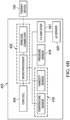
- FIG. 1 is a simplified functional block diagram of an example embodiment of a therapy system 100 that can provide negative-pressure therapy with instillation of treatment solutions in accordance with this specification.
- the therapy system 100 may include a negative-pressure supply, and may include or be configured to be coupled to a distribution component, such as a dressing.
- a distribution component may refer to any complementary or ancillary component configured to be fluidly coupled to a negative-pressure supply between a negative-pressure supply and a tissue site.
- a distribution component is preferably detachable, and may be disposable, reusable, or recyclable.
- a dressing 102 is illustrative of a distribution component that may be coupled to a negative-pressure source and other components.
- the therapy system 100 may be packaged as a single, integrated unit such as a therapy system including all of the components shown in Figure 1 that are fluidly coupled to the dressing 102.
- the therapy system may be, for example, a V.A.C. Ulta TM System available from Kinetic Concepts, Inc. of San Antonio, Texas.
- the dressing 102 may be fluidly coupled to a negative-pressure source 104.
- a dressing may include a cover, a tissue interface, or both in some embodiments.
- the dressing 102 for example, may include a cover 106, a dressing interface 107, and a tissue interface 108.
- a computer or a controller device, such as a controller 110, may also be coupled to the negative-pressure source 104.
- the cover 106 may be configured to cover the tissue interface 108 and the tissue site and may be adapted to seal the tissue interface and create a therapeutic environment proximate to a tissue site for maintaining a negative pressure at the tissue site.
- the dressing interface 107 may be configured to fluidly couple the negative-pressure source 104 to the therapeutic environment of the dressing.
- the therapy system 100 may optionally include a fluid container, such as a container 112, fluidly coupled to the dressing 102 and to the negative-pressure source 104.
- the therapy system 100 may also include a source of instillation solution, such as a solution source 114.
- a distribution component may be fluidly coupled to a fluid path between a solution source and a tissue site in some embodiments.
- an instillation pump 116 may be coupled to the solution source 114, as illustrated in the example embodiment of Figure 1 .
- the instillation pump 116 may also be fluidly coupled to the negative-pressure source 104 such as, for example, by a fluid conductor 119.
- the instillation pump 116 may be directly coupled to the negative-pressure source 104, as illustrated in Figure 1 , but may be indirectly coupled to the negative-pressure source 104 through other distribution components in some embodiments.
- the instillation pump 116 may be fluidly coupled to the negative-pressure source 104 through the dressing 102.
- the instillation pump 116 and the negative-pressure source 104 may be fluidly coupled to two different locations on the tissue interface 108 by two different dressing interfaces.
- the negative-pressure source 104 may be fluidly coupled to the dressing interface 107 while the instillation pump 116 may be fluidly to the coupled to dressing interface 107 or a second dressing interface 117.
- the instillation pump 116 and the negative-pressure source 104 may be fluidly coupled to two different tissue interfaces by two different dressing interfaces, one dressing interface for each tissue interface (not shown).
- the therapy system 100 also may include sensors to measure operating parameters and provide feedback signals to the controller 110 indicative of the operating parameters properties of fluids extracted from a tissue site.
- the therapy system 100 may include a pressure sensor 120, an electric sensor 124, or both, coupled to the controller 110.
- the pressure sensor 120 may be fluidly coupled or configured to be fluidly coupled to a distribution component such as, for example, the negative-pressure source 104 either directly or indirectly through the container 112.
- the pressure sensor 120 may be configured to measure pressure being generated by the negative-pressure source 104, i.e., the pump pressure (PP).
- the electric sensor 124 also may be coupled to the negative-pressure source 104 to measure the pump pressure (PP).
- the electric sensor 124 may be fluidly coupled proximate the output of the output of the negative-pressure source 104 to directly measure the pump pressure (PP). In other example embodiments, the electric sensor 124 may be electrically coupled to the negative-pressure source 104 to measure the changes in the current in order to determine the pump pressure (PP).
- Distribution components may be fluidly coupled to each other to provide a distribution system for transferring fluids (i.e., liquid and/or gas).
- a distribution system may include various combinations of fluid conductors and fittings to facilitate fluid coupling.
- a fluid conductor generally includes any structure with one or more lumina adapted to convey a fluid between two ends, such as a tube, pipe, hose, or conduit.
- a fluid conductor is an elongated, cylindrical structure with some flexibility, but the geometry and rigidity may vary.
- Some fluid conductors may be molded into or otherwise integrally combined with other components.
- a fitting can be used to mechanically and fluidly couple components to each other.
- a fitting may comprise a projection and an aperture.
- the projection may be configured to be inserted into a fluid conductor so that the aperture aligns with a lumen of the fluid conductor.
- a valve is a type of fitting that can be used to control fluid flow. For example, a check valve can be used to substantially prevent return flow.
- a port is another example of a fitting.
- a port may also have a projection, which may be threaded, flared, tapered, barbed, or otherwise configured to provide a fluid seal when coupled to a component.
- distribution components may also be coupled by virtue of physical proximity, being integral to a single structure, or being formed from the same piece of material. Coupling may also include mechanical, thermal, electrical, or chemical coupling (such as a chemical bond) in some contexts.
- a tube may mechanically and fluidly couple the dressing 102 to the container 112 in some embodiments.
- components of the therapy system 100 may be coupled directly or indirectly.
- the negative-pressure source 104 may be directly coupled to the controller 110 and may be indirectly coupled to the dressing interface 107 through the container 112 by conduit 126 and conduit 130, also referred to herein as negative pressure conduit 126 and negative pressure conduit 130.
- the pressure sensor 120 may be fluidly coupled to the dressing 102 directly (not shown) or indirectly by conduit 121 and conduit 122. Additionally, the instillation pump 116 may be coupled indirectly to the dressing interface 107 through the solution source 114 and an instillation regulator 115 by fluid conductors 132 and 133, also referred to herein as instillation conduit 132 and instillation conduit 133.
- the instillation regulator 115 may be electrically coupled to the controller 110 (not shown) that may be programmed along with the instillation pump 116 to deliver instillation fluid in a controlled fashion. Alternatively, the instillation pump 116 may be coupled indirectly to the second dressing interface 117 through the solution source 114 and the instillation regulator 115 by fluid conductors 132, 133 and 134.
- Some embodiments of the therapy system 100 may include a solution source, such as solution source 114, without an instillation pump, such as the instillation pump 116.
- the solution source 114 may be fluidly coupled directly or indirectly to the dressing interface 107 and may further include the instillation regulator 115 electrically coupled to the controller 110 as described above.
- the negative pressure source 104 may apply negative pressure to the dressing interface 107 through the container 112 and the negative pressure conduit 130 to create a vacuum within the spaces formed by the dressing interface 107 and the tissue interface 108. The vacuum within the spaces would draw instillation fluid into the spaces for cleansing or providing therapy treatment to the tissue site.
- the controller 110 may be programmed to modulate the instillation regulator 115 to control the flow of instillation fluid into the spaces.
- the therapy system 100 may include both the instillation pump 116 and the negative pressure source 104 to alternately deliver instillation fluid to the dressing interface 107 by providing a positive pressure to the solution source 114 and a negative pressure directly to the dressing interface 107, respectively. Any of the embodiments described above may be utilized to periodically clean, rinse, or hydrate the tissue site using saline along with other pH-modulating instillation fluids such as weak acidic acids.
- the fluid mechanics of using a negative-pressure source to reduce pressure in another component or location, such as within a sealed therapeutic environment, can be mathematically complex.
- the basic principles of fluid mechanics applicable to negative-pressure therapy and instillation are generally well-known to those skilled in the art, and the process of reducing pressure may be described illustratively herein as "delivering,” “distributing,” or “generating” negative pressure, for example.
- exudates and other fluids flow toward lower pressure along a fluid path.
- downstream typically implies something in a fluid path relatively closer to a source of negative pressure or further away from a source of positive pressure.
- upstream implies something relatively further away from a source of negative pressure or closer to a source of positive pressure.
- fluid inlet or “outlet” in such a frame of reference. This orientation is generally presumed for purposes of describing various features and components herein.
- the fluid path may also be reversed in some applications (such as by substituting a positive-pressure source for a negative-pressure source) and this descriptive convention should not be construed as a limiting convention.
- Negative pressure generally refers to a pressure less than a local ambient pressure, such as the ambient pressure in a local environment external to a sealed therapeutic environment provided by the dressing 102.
- the local ambient pressure may also be the atmospheric pressure at which a tissue site is located.
- the pressure may be less than a hydrostatic pressure associated with tissue at the tissue site.
- values of pressure stated herein are gauge pressures.
- references to increases in negative pressure typically refer to a decrease in absolute pressure, while decreases in negative pressure typically refer to an increase in absolute pressure.
- the pressure is generally a low vacuum, also commonly referred to as a rough vacuum, between -5 mm Hg (-667 Pa) and -500 mm Hg (-66.7 kPa).
- a rough vacuum between -5 mm Hg (-667 Pa) and -500 mm Hg (-66.7 kPa).
- Common therapeutic ranges are between -75 mm Hg (-9.9 kPa) and -300 mm Hg (-39.9 kPa).
- a negative-pressure supply such as the negative-pressure source 104, may be a reservoir of air at a negative pressure, or may be a manual or electrically-powered device that can reduce the pressure in a sealed volume, such as a vacuum pump, a suction pump, a wall suction port available at many healthcare facilities, or a micro-pump, for example.
- a negative-pressure supply may be housed within or used in conjunction with other components, such as sensors, processing units, alarm indicators, memory, databases, software, display devices, or user interfaces that further facilitate therapy.
- the negative-pressure source 104 may be combined with the controller 110 and other components into a therapy unit.
- a negative-pressure supply may also have one or more supply ports configured to facilitate coupling and de-coupling the negative-pressure supply to one or more distribution components.
- the tissue interface 108 can be generally adapted to contact a tissue site.
- the tissue interface 108 may be partially or fully in contact with the tissue site. If the tissue site is a wound, for example, the tissue interface 108 may partially or completely fill the wound or may be placed over the wound.
- the tissue interface 108 may take many forms, and may have many sizes, shapes, or thicknesses depending on a variety of factors, such as the type of treatment being implemented or the nature and size of a tissue site. For example, the size and shape of the tissue interface 108 may be adapted to the contours of deep and irregular shaped tissue sites. Moreover, any or all of the surfaces of the tissue interface 108 may have projections or an uneven, course, or jagged profile that can induce strains and stresses on a tissue site, which can promote granulation at the tissue site.
- the tissue interface 108 may be a manifold such as manifold 408 shown in Figure 4 .
- a "manifold" in this context generally includes any substance or structure providing a plurality of pathways adapted to collect or distribute fluid across a tissue site under pressure.
- a manifold may be adapted to receive negative pressure from a source and distribute negative pressure through multiple apertures across a tissue site, which may have the effect of collecting fluid from across a tissue site and drawing the fluid toward the source.
- the fluid path may be reversed, or a secondary fluid path may be provided to facilitate delivering fluid across a tissue site.
- a manifold may be a porous foam material having interconnected cells or pores.
- cellular foam, open-cell foam, reticulated foam, porous tissue collections, and other porous material such as gauze or felted mat generally include pores, edges, and/or walls adapted to form interconnected fluid channels.
- Liquids, gels, and other foams may also include or be cured to include apertures and fluid pathways.
- a manifold may additionally or alternatively comprise projections that form interconnected fluid pathways.
- a manifold may be molded to provide surface projections that define interconnected fluid pathways.
- the average pore size of a foam manifold may vary according to needs of a prescribed therapy.
- the tissue interface 108 may be a foam manifold having pore sizes in a range of 400-600 microns.
- the tensile strength of the tissue interface 108 may also vary according to needs of a prescribed therapy. For example, the tensile strength of a foam may be increased for instillation of topical treatment solutions.
- the tissue interface 108 may be an open-cell, reticulated polyurethane foam such as GranuFoam° dressing or VeraFlo° foam, both available from Kinetic Concepts, Inc. of San Antonio, Texas.
- the tissue interface 108 may be either hydrophobic or hydrophilic.
- the tissue interface 108 may also wick fluid away from a tissue site, while continuing to distribute negative pressure to the tissue site.
- the wicking properties of the tissue interface 108 may draw fluid away from a tissue site by capillary flow or other wicking mechanisms.
- An example of a hydrophilic foam is a polyvinyl alcohol, open-cell foam such as V.A.C. WhiteFoam° dressing available from Kinetic Concepts, Inc. of San Antonio, Texas.
- Other hydrophilic foams may include those made from polyether.
- Other foams that may exhibit hydrophilic characteristics include hydrophobic foams that have been treated or coated to provide hydrophilicity.
- the tissue interface 108 may further promote granulation at a tissue site when pressure within the sealed therapeutic environment is reduced.
- any or all of the surfaces of the tissue interface 108 may have an uneven, coarse, or jagged profile that can induce microstrains and stresses at a tissue site if negative pressure is applied through the tissue interface 108.
- the tissue interface 108 may be constructed from bioresorbable materials. Suitable bioresorbable materials may include, without limitation, a polymeric blend of polylactic acid (PLA) and polyglycolic acid (PGA). The polymeric blend may also include without limitation polycarbonates, polyfumarates, and capralactones.
- the tissue interface 108 may further serve as a scaffold for new cell-growth, or a scaffold material may be used in conjunction with the tissue interface 108 to promote cell-growth.
- a scaffold is generally a substance or structure used to enhance or promote the growth of cells or formation of tissue, such as a three-dimensional porous structure that provides a template for cell growth.
- Illustrative examples of scaffold materials include calcium phosphate, collagen, PLA/PGA, coral hydroxy apatites, carbonates, or processed allograft materials.
- the cover 106 may provide a bacterial barrier and protection from physical trauma.
- the cover 106 may also be constructed from a material that can reduce evaporative losses and provide a fluid seal between two components or two environments, such as between a therapeutic environment and a local external environment.
- the cover 106 may be, for example, an elastomeric film or membrane that can provide a seal adequate to maintain a negative pressure at a tissue site for a given negative-pressure source.
- the cover 106 may have a high moisture-vapor transmission rate (MVTR) in some applications.
- the MVTR may be at least 300 g/m ⁇ 2 per twenty-four hours in some embodiments.
- the cover 106 may be a polymer drape, such as a polyurethane film, that is permeable to water vapor but impermeable to liquid. Such drapes typically have a thickness in the range of 25-50 microns. For permeable materials, the permeability generally should be low enough that a desired negative pressure may be maintained. In some embodiments, the cover may be a drape such as drape 406 shown in Figure 4 .
- An attachment device may be used to attach the cover 106 to an attachment surface, such as undamaged epidermis, a gasket, or another cover.
- the attachment device may take many forms.
- an attachment device may be a medically-acceptable, pressure-sensitive adhesive that extends about a periphery, a portion, or an entire sealing member.
- some or all of the cover 106 may be coated with an acrylic adhesive having a coating weight between 25-65 grams per square meter (g.s.m.). Thicker adhesives, or combinations of adhesives, may be applied in some embodiments to improve the seal and reduce leaks.
- Other example embodiments of an attachment device may include a double-sided tape, paste, hydrocolloid, hydrogel, silicone gel, or organogel.
- the dressing interface 107 may facilitate coupling the negative-pressure source 104 to the dressing 102.
- the negative pressure provided by the negative-pressure source 104 may be delivered through the conduit 130 to a negative-pressure interface, which may include an elbow portion.
- the negative-pressure interface may be a T.R.A.C.° Pad or Sensa T.R.A.C.° Pad available from KCI of San Antonio, Texas.
- the negative-pressure interface enables the negative pressure to be delivered through the cover 106 and to the tissue interface 108 and the tissue site.
- the elbow portion may extend through the cover 106 to the tissue interface 108, but numerous arrangements are possible.
- a controller such as the controller 110, may be a microprocessor or computer programmed to operate one or more components of the therapy system 100, such as the negative-pressure source 104.
- the controller 110 may be a microcontroller, which generally comprises an integrated circuit containing a processor core and a memory programmed to directly or indirectly control one or more operating parameters of the therapy system 100. Operating parameters may include the power applied to the negative-pressure source 104, the pressure generated by the negative-pressure source 104, or the pressure distributed to the tissue interface 108, for example.
- the controller 110 is also preferably configured to receive one or more input signals, such as a feedback signal, and programmed to modify one or more operating parameters based on the input signals.
- Sensors such as the pressure sensor 120 or the electric sensor 124, are generally known in the art as any apparatus operable to detect or measure a physical phenomenon or property, and generally provide a signal indicative of the phenomenon or property that is detected or measured.
- the pressure sensor 120 and the electric sensor 124 may be configured to measure one or more operating parameters of the therapy system 100.
- the pressure sensor 120 may be a transducer configured to measure pressure in a pneumatic pathway and convert the measurement to a signal indicative of the pressure measured.
- the pressure sensor 120 may be a piezoresistive strain gauge.
- the electric sensor 124 may optionally measure operating parameters of the negative-pressure source 104, such as the voltage or current, in some embodiments.
- the signals from the pressure sensor 120 and the electric sensor 124 are suitable as an input signal to the controller 110, but some signal conditioning may be appropriate in some embodiments.
- the signal may need to be filtered or amplified before it can be processed by the controller 110.
- the signal is an electrical signal that is transmitted and/or received on by wire or wireless means, but may be represented in other forms, such as an optical signal.
- the solution source 114 is representative of a container, canister, pouch, bag, or other storage component, which can provide a solution for instillation therapy.
- Compositions of solutions may vary according to a prescribed therapy, but examples of solutions that may be suitable for some prescriptions include hypochlorite-based solutions, silver nitrate (0.5%), sulfur-based solutions, biguanides, cationic solutions, and isotonic solutions. Examples of such other therapeutic solutions that may be suitable for some prescriptions include hypochlorite-based solutions, silver nitrate (0.5%), sulfur-based solutions, biguanides, cationic solutions, and isotonic solutions.
- the solution source 114 may include a storage component for the solution and a separate cassette for holding the storage component and delivering the solution to the tissue site 150, such as a V.A.C. VeraLink TM Cassette available from Kinetic Concepts, Inc. of San Antonio, Texas.
- the container 112 may also be representative of a container, canister, pouch, or other storage component, which can be used to collect and manage exudates and other fluids withdrawn from a tissue site.
- a rigid container such as, for example, a container 162 may be preferred or required for collecting, storing, and disposing of fluids.
- fluids may be properly disposed of without rigid container storage, and a re-usable container could reduce waste and costs associated with negative-pressure therapy.
- the container 112 may comprise a canister having a collection chamber, a first inlet fluidly coupled to the collection chamber and a first outlet fluidly coupled to the collection chamber and adapted to receive negative pressure from a source of negative pressure.
- a first fluid conductor may comprise a first member such as, for example, the conduit 130 fluidly coupled between the first inlet and the tissue interface 108 by the negative-pressure interface described above, and a second member such as, for example, the conduit 126 fluidly coupled between the first outlet and a source of negative pressure whereby the first conductor is adapted to provide negative pressure within the collection chamber to the tissue site.
- the therapy system 100 may also comprise a flow regulator such as, for example, a vent regulator 118 fluidly coupled to a source of ambient air to provide a controlled or managed flow of ambient air to the sealed therapeutic environment provided by the dressing 102 and ultimately the tissue site.
- a flow regulator such as, for example, a vent regulator 118 fluidly coupled to a source of ambient air to provide a controlled or managed flow of ambient air to the sealed therapeutic environment provided by the dressing 102 and ultimately the tissue site.
- the vent regulator 118 may control the flow of ambient fluid to purge fluids and exudates from the sealed therapeutic environment.
- the vent regulator 118 may be fluidly coupled by a fluid conductor or vent conduit 135 through the dressing interface 107 to the tissue interface 108.
- the vent regulator 118 may be configured to fluidly couple the tissue interface 108 to a source of ambient air as indicated by a dashed arrow.
- the vent regulator 118 may be disposed within the therapy system 100 rather than being proximate to the dressing 102 so that the air flowing through the vent regulator 118 is less susceptible to accidental blockage during use. In such embodiments, the vent regulator 118 may be positioned proximate the container 112 and/or proximate a source of ambient air where the vent regulator 118 is less likely to be blocked during usage.
- the tissue interface 108 may be placed within, over, on, or otherwise proximate a tissue site, such as tissue site 150.
- the cover 106 may be placed over the tissue interface 108 and sealed to an attachment surface near the tissue site 150.
- the cover 106 may be sealed to undamaged epidermis peripheral to a tissue site.
- the dressing 102 can provide a sealed therapeutic environment proximate to a tissue site, substantially isolated from the external environment, and the negative-pressure source 104 can reduce the pressure in the sealed therapeutic environment. Negative pressure applied across the tissue site through the tissue interface 108 in the sealed therapeutic environment can induce macrostrain and microstrain in the tissue site, as well as remove exudates and other fluids from the tissue site, which can be collected in container 112.
- the controller 110 may receive and process data, such as data related to the pressure distributed to the tissue interface 108 from the pressure sensor 120.
- the controller 110 may also control the operation of one or more components of therapy system 100 to manage the pressure distributed to the tissue interface 108 for application to the wound at the tissue site 150, which may also be referred to as the wound pressure (WP).
- controller 110 may include an input for receiving a desired target pressure (TP) set by a clinician or other user and may be program for processing data relating to the setting and inputting of the target pressure (TP) to be applied to the tissue site 150.
- TP desired target pressure
- TP target pressure
- the target pressure (TP) may be a fixed pressure value determined by a user/caregiver as the reduced pressure target desired for therapy at the tissue site 150 and then provided as input to the controller 110.
- the user may be a nurse or a doctor or other approved clinician who prescribes the desired negative pressure to which the tissue site 150 should be applied.
- the desired negative pressure may vary from tissue site to tissue site based on the type of tissue forming the tissue site 150, the type of injury or wound (if any), the medical condition of the patient, and the preference of the attending physician.
- the negative-pressure source 104 is controlled to achieve the target pressure (TP) desired for application to the tissue site 150.
- FIG. 2A a graph illustrating an illustrative embodiment of pressure control modes 200 that may be used for the negative-pressure and instillation therapy system of Figure 1 is shown wherein the x-axis represents time in minutes (min) and/or seconds (sec) and the y-axis represents pressure generated by a pump in Torr (mmHg) that varies with time in a continuous pressure mode and an intermittent pressure mode that may be used for applying negative pressure in the therapy system.
- the target pressure (TP) may be set by the user in a continuous pressure mode as indicated by solid line 201 and dotted line 202 wherein the wound pressure (WP) is applied to the tissue site 150 until the user deactivates the negative-pressure source 104.
- the target pressure (TP) may also be set by the user in an intermittent pressure mode as indicated by solid lines 201, 203 and 205 wherein the wound pressure (WP) is cycled between the target pressure (TP) and atmospheric pressure.
- the target pressure (TP) may be set by the user at a value of 125 mmHg for a specified period of time (e.g., 5 min) followed by the therapy being turned off for a specified period of time (e.g., 2 min) as indicated by the gap between the solid lines 203 and 205 by venting the tissue site 150 to the atmosphere, and then repeating the cycle by turning the therapy back on as indicated by solid line 205 which consequently forms a square wave pattern between the target pressure (TP) level and atmospheric pressure.
- the decrease in the wound pressure (WP) at the tissue site 150 from ambient pressure to the target pressure (TP) is not instantaneous, but rather gradual depending on the type of therapy equipment and dressing being used for the particular therapy treatment.
- the negative-pressure source 104 and the dressing 102 may have an initial rise time as indicated by the dashed line 207 that may vary depending on the type of dressing and therapy equipment being used.
- the initial rise time for one therapy system may be in the range between about 20-30 mmHg/second or, more specifically, equal to about 25 mmHg/second, and in the range between about 5-10 mmHg/second for another therapy system.
- the repeating rise time as indicated by the solid line 205 may be a value substantially equal to the initial rise time as indicated by the dashed line 207.
- the target pressure may also be a variable target pressure (VTP) controlled or determined by controller 110 that varies in a dynamic pressure mode.
- VTP variable target pressure
- the variable target pressure (VTP) may vary between a maximum and minimum pressure value that may be set as an input determined by a user as the range of negative pressures desired for therapy at the tissue site 150.
- the variable target pressure (VTP) may also be processed and controlled by controller 110 that varies the target pressure (TP) according to a predetermined waveform such as, for example, a sine waveform or a saw-tooth waveform or a triangular waveform, that may be set as an input by a user as the predetermined or time-varying reduced pressures desired for therapy at the tissue site 150.
- VTP variable target pressure
- the variable target pressure may be a reduced pressure that provides an effective treatment by applying reduced pressure to tissue site 150 in the form of a triangular waveform varying between a minimum and maximum pressure of 50-125 mmHg with a rise time 212 set at a rate of +25 mmHg/min.
- variable target pressure may be a reduced pressure that applies reduced pressure to tissue site 150 in the form of a triangular waveform varying between 25-125 mmHg with a rise time 212 set at a rate of +30 mmHg/min and a descent time 211 set at -30 mmHg/min.
- the type of system and tissue site determines the type of reduced pressure therapy to be used.
- FIG. 3 is a flow chart illustrating an illustrative embodiment of a therapy method 300 that may be used for providing negative-pressure and instillation therapy for delivering an antimicrobial solution or other treatment solution to a dressing at a tissue site.
- the controller 110 receives and processes data, such as data related to fluids provided to the tissue interface 108.
- data may include the type of instillation solution prescribed by a clinician, the volume of fluid or solution to be instilled to the tissue site (“fill volume”), and the amount of time needed to soak the tissue interface (“soak time”) before applying a negative pressure to the tissue site.
- the fill volume may be, for example, between 10 and 500 mL, and the soak time may be between one second to 30 minutes.
- the controller 110 may also control the operation of one or more components of the therapy system 100 to manage the instillation fluids delivered from the solution source 114 to the tissue site 150 for cleaning and/or providing therapy treatment to the wound along with the negative pressure therapy as described above.
- fluid may be instilled to the tissue site 150 by applying a negative pressure from the negative-pressure source 104 to reduce the pressure at the tissue site 150 and draw the instillation fluid into the dressing 102 as indicated at 302 and described above in more detail.
- fluid may be instilled to the tissue site 150 by applying a positive pressure from the negative-pressure source 104 (not shown) or the instillation pump 116 to force the instillation fluid from the solution source 114 to the tissue interface 108 as indicated at 304.
- fluid may be instilled to the tissue site 150 by elevating the solution source 114 to height sufficient to force the instillation fluid into the tissue interface 108 by the force of gravity as indicated at 306.
- the therapy method 300 includes instilling fluid into the tissue interface 108 by either drawing or forcing the fluid into the tissue interface 108 as indicated at 310.
- the therapy method 300 may control the fluid dynamics of applying the fluid solution to the tissue interface 108 at 312 by providing a continuous flow of fluid at 314 or an intermittent flow of fluid for soaking the tissue interface 108 at 316.
- the therapy method 300 may include the application of negative pressure to the tissue interface 108 to provide either the continuous flow or intermittent soaking flow of fluid at 320.
- the application of negative pressure may be implemented to provide a continuous pressure mode of operation at 322 as described above to achieve a continuous flow rate of instillation fluid through the tissue interface 108 or a dynamic pressure mode of operation at 324 as described above to vary the flow rate of instillation fluid through the tissue interface 108.
- the application of negative pressure may be implemented to provide an intermittent mode of operation at 326 as described above to allow instillation fluid to soak into the tissue interface 108 as described above.
- a specific fill volume and the soak time may be provided depending, for example, on the type of wound being treated and the type of dressing 102 being utilized to treat the wound.
- the therapy method 300 may begin may be utilized using any one of the three modes of operation at 330 as described above.
- the controller 110 may be utilized to select any one of these three modes of operation and the duration of the negative pressure therapy as described above before commencing another instillation cycle at 340 by instilling more fluid at 310.
- the tissue site 150 may include, without limitation, any irregularity with a tissue, such as an open wound, surgical incision, or diseased tissue.
- the therapy system 100 is presented in the context of a tissue site that includes a wound that may extend through the epidermis and the dermis and may reach into the hypodermis or subcutaneous tissue.
- the therapy system 100 may be used to treat a wound of any depth, as well as many different types of wounds including open wounds, incisions, or other tissue sites.
- the tissue site 150 may be the bodily tissue of any human, animal, or other organism, including bone tissue, adipose tissue, muscle tissue, dermal tissue, vascular tissue, connective tissue, cartilage, tendons, ligaments, or any other tissue.
- Treatment of the tissue site 150 may include removal of fluids originating from the tissue site 150, such as exudates or ascites, or fluids instilled into the dressing to cleanse or treat the tissue site 150, such as antimicrobial solutions.
- the therapy system 100 may be packaged as a single, integrated unit such as a therapy system including all of the components shown in Figure 1 that are fluidly coupled to the dressing 102.
- an integrated therapy unit may include the negative-pressure source 104, the controller 110, the pressure sensor 120, and the container 112 which may be fluidly coupled to the dressing interface 107.
- the negative-pressure source 104 is indirectly coupled to the dressing interface 107 through the container 112 by conduit 126 and conduit 130
- the pressure sensor 120 is indirectly coupled to the dressing interface 107 by conduit 121 and conduit 122 as described above.
- the negative pressure conduit 130 and the pressure sensing conduit 122 may be combined in a single fluid conductor that can be, for example, a multi-lumen tubing comprising a central primary lumen that functions as the negative pressure conduit 130 for delivering negative pressure to the dressing interface 107 and several peripheral auxiliary lumens that function as the pressure sensing conduit 122 for sensing the pressure that the dressing interface 107 delivers to the tissue interface 108.
- a single fluid conductor can be, for example, a multi-lumen tubing comprising a central primary lumen that functions as the negative pressure conduit 130 for delivering negative pressure to the dressing interface 107 and several peripheral auxiliary lumens that function as the pressure sensing conduit 122 for sensing the pressure that the dressing interface 107 delivers to the tissue interface 108.
- the negative pressure measured by the pressure sensor 120 may be different from the wound pressure (WP) actually being applied to the tissue site 150.
- WP wound pressure
- Such pressure differences must be approximated in order to adjust the negative-pressure source 104 to deliver the pump pressure (PP) necessary to provide the desired or target pressure (TP) to the tissue interface 108. Moreover, such pressure differences and predictability may be exacerbated by viscous fluids such as exudates being produced by the tissue site or utilizing a single therapy device including a pressure sensor to deliver negative pressure to multiple tissue sites on a single patient.
- the integrated pressure sensor may be used with or without the remote pressure sensor 120 that is indirectly coupled to the dressing interface 107.
- the dressing interface 107 may comprise a housing having a therapy cavity that opens to the tissue site when positioned thereon.
- the integrated pressure sensor may have a sensing portion disposed within the therapy cavity along with other sensors including, for example, a temperature sensor, a humidity sensor, and a pH sensor.
- the sensors may be electrically coupled to the controller 110 outside the therapy cavity to provide data indicative of the pressure, temperature, humidity, and acidity properties within the therapeutic space of the therapy cavity.
- the sensors may be electrically coupled to the controller 110, for example, by wireless means.
- the dressing 102 may include the cover 106, the dressing interface 107, and the tissue interface 108.
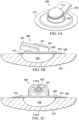
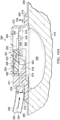
- a first dressing is shown comprising a dressing interface 400, a cover or drape 406, and a tissue interface or manifold 408 disposed adjacent a tissue site 410, all of which may be functionally similar in part to the dressing interface 107, the cover 106, and the tissue interface 108, respectively, as described above.
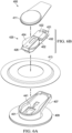
- the dressing interface 400 may comprise a housing 401 and a wall 402 disposed within the housing 401 wherein the wall 402 forms a recessed space or a therapy cavity 403 that opens to the manifold 408 when disposed at the tissue site 410 and a component cavity 404 opening away from the tissue site 410 of the upper portion of the dressing interface 400.
- sensing portions of various sensors may be disposed within the therapy cavity 403, and electrical devices associated with the sensors may be disposed within the component cavity 404 and electrically coupled to the sensing portions through the wall 402. Electrical devices disposed within the component cavity 404 may include components associated with some example embodiments of the therapy system of Figure 1 .
- the dressing interface 400 and the therapy cavity 403 are functionally similar to the dressing interface 107 as described above, the dressing interface 400 further comprises the wall 402, the sensors, and the associated electrical devices described below in more detail.
- the housing 401 may further comprise a neck portion or neck 407 fluidly coupled to a conduit 405.
- the housing 401 may further comprise a flange portion or flange 409 having flow channels (see Figure 8 ) configured to be fluidly coupled to the therapy cavity 403 when disposed on the manifold 408.
- the neck 407 of the housing 401 may include portions of both the therapy cavity 403 and the component cavity 404. That portion of the neck 407 extending into the therapy cavity 403 is fluidly coupled to the conduit 405, while the portion extending into the component cavity 404 may contain some of the electrical devices.
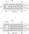
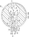
- the conduit 405 may comprise a primary lumen or a negative pressure lumen 430 and separate auxiliary lumens such as, for example, an instillation lumen 433 and a venting lumen 435 fluidly coupled by the neck 407 of the housing 401 to the therapy cavity 403.
- the negative pressure lumen 430 is similar to the negative pressure conduit 130 that may be coupled indirectly to the negative-pressure source 104.
- the venting lumen 435 is similar to the vent conduit 135 that may be fluidly coupled to the vent regulator 118 for purging fluids from the therapy cavity 403.
- the instillation lumen 433 is similar to the instillation conduit 133 that may be fluidly coupled directly or indirectly to the solution source 114 for flushing fluids from the therapy cavity 403 for removal by the application of negative pressure through the negative pressure lumen 430.
- the component cavity 404 containing the electrical devices may be open to the ambient environment such that the electrical devices are exposed to the ambient environment.
- the component cavity 404 may be closed by a cover such as, for example, a cap 411 to protect the electrical devices.
- the component cavity 404 covered by the cap 411 may still be vented to the ambient environment to provide cooling to the electrical devices and a source of ambient pressure for a pressure sensor disposed in the therapy cavity 403 as described in more detail below.
- the first dressing interface 400 may further comprise a drape ring 413 covering the circumference of the flange 409 and the adjacent portion of the drape 406 to seal the therapy cavity 403 of the housing 401 over the manifold 408 and the tissue site 410.
- the drape ring 413 may comprise a polyurethane film including and an attachment device such as, for example, an acrylic, polyurethane gel, silicone, or hybrid combination of the foregoing adhesives (not shown) to attach the drape ring 413 to the flange 409 and the drape 406.
- the attachment device of drape ring 413 may be a single element of silicon or hydrocolloid with the adhesive on each side that functions as a gasket between the drape 406 and the flange 409.
- the drape ring 413 may be similar to the cover 106 and/or the attachment device described above in more detail.
- a pressure sensor 416, a temperature and humidity sensor 418, and a pH sensor 420 may be disposed in the housing 401 with each one having a sensing portion extending into the therapy cavity 403 of the housing 401 and associated electronics disposed within the component cavity 404.
- the housing 401 may include other types of sensors, or combinations of the foregoing sensors, such as, for example, oxygen sensors.
- the sensors may be coupled to or mounted on the wall 402 and electrically coupled to electrical components and circuits disposed within the component cavity 404 by electrical conductors extending through the wall 402.
- the electrical conductors extend through pathways in the wall 402 while keeping the therapy cavity 403 electrically and pneumatically isolated from the component cavity 404.
- the wall 402 may comprise a circuit board 432 on which the electrical circuits and/or components may be printed or mounted.
- the circuit board 432 may be the wall 402 that covers an opening between the therapy cavity 403 and the component cavity 404, and pneumatically seals the therapy cavity 403 from the component cavity 404 when seated over the opening.
- the electrical circuits and/or components associated with the sensors that are mounted on the circuit board 432 within the component cavity 404 may be electrically coupled to the controller 110 to interface with the rest of the therapy system 100 as described above.
- the electrical circuits and/or components may be electrically coupled to the controller 110 by a conductor that may be a component of the conduit 405.
- a communications module 422 may be disposed in the component cavity 404 of the housing 401 and mounted on the circuit board 432 within the component cavity 404. Using a wireless communications module 422 has the advantage of eliminating an electrical conductor between the dressing interface 400 and the integrated portion of the therapy system 100 that may become entangled with the conduit 405 when in use during therapy treatments.
- the electrical circuits and/or components associated with the sensors along with the terminal portion of the sensors may be electrically coupled to the controller 110 by wireless means such as an integrated device implementing Bluetooth° Low Energy wireless technology.
- the communications module 422 may be a Bluetooth° Low Energy system-on-chip that includes a microprocessor (an example of the microprocessors referred to hereinafter) such as the nRF51822 chip available from Nordic Semiconductor.
- the wireless communications module 422 may be implemented with other wireless technologies suitable for use in the medical environment.
- a voltage regulator 423 for signal conditioning and a power source 424 may be disposed within the component cavity 404 of the housing 401 and mounted on the circuit board 432.
- the power supply 424 may be secured to the circuit board 432 by a bracket 426.
- the power source 424 may be, for example, a battery that may be a coin battery having a low-profile that provides a 3-volt source for the communications module 422 and the other electronic components within the component cavity 404 associated with the sensors.
- the sensors, the electrical circuits and/or components associated with the sensors, the wall 402 and/or the circuit board 432, the communications module 422, and the power source 424 may be integrated into a single package and referred to hereinafter as a sensor assembly 425 as shown in Figure 6B .
- the wall 402 of the sensor assembly 425 may be the circuit board 432 itself as described above that provides a seal between tissue site 410 and the atmosphere when positioned over the opening between the therapy cavity 403 and the component cavity 404 of the housing 401 and functions as the wall 402 within the housing 401 that forms the therapy cavity 403.
- the bottom surface may comprise features or channels to direct the flow of liquids and/or exudates away from the sensors out of the therapy cavity 403 into the negative pressure lumen 430 when negative pressure is being applied to the therapy cavity 403.
- these channels may be molded into the bottom surface of the flange 409 to form a plurality of serrated guide channels 437, perimeter collection channels 438, and intermediate collection channels 439.
- the serrated guide channels 437 may be positioned and oriented in groups on bottom surface to directly capture and channel at least half of the liquids being drawn into the therapy cavity 403 with the groups of serrated guide channels 437, and indirectly channel a major portion of the balance of the liquids being drawn into the therapy cavity 403 between the groups of serrated guide channels 437.
- perimeter collection channels 438 and intermediate collection channels 439 redirect the flow of liquids that are being drawn in between the groups of radially-oriented serrated guide channels 437 into the guide channels 437. An example of this redirected flow is illustrated by bolded flow arrows 436.
- a portion of the housing 401 within the therapy cavity 403 may comprise a second set of serrated guide channels 427 spaced apart and radially-oriented to funnel liquids being drawn into the therapy cavity 403 from the flange 409 into the negative pressure lumen 430.
- the channels may be arranged in different patterns.
- the sensor assembly 425 may comprise a pressure sensor 416, a humidity sensor 418, a temperature sensor as a component of either the pressure sensor 416 or the humidity sensor 418, and a pH sensor 420.
- Each of the sensors may comprise a sensing portion extending into the therapy cavity 403 of the housing 401 and a terminal portion electrically coupled to the electrical circuits and/or components within the component cavity 404.
- the housing 401 may comprise a sensor bracket 441 that may be a molded portion of the housing 401 within the therapy cavity 403 in some embodiments.
- the sensor bracket 441 may be structured to house and secure the pressure sensor 416 on the circuit board 432 within the therapy cavity 403 of the sensor assembly 425 that provides a seal between tissue site 410 and the atmosphere as described above.
- the pressure sensor 416 may be a differential gauge comprising a sensing portion 442 and a terminal portion or vent 443.
- the vent 443 of the pressure sensor 416 may be fluidly coupled through the circuit board 432 to the component cavity 404 and the atmosphere by a vent hole 444 extending through the circuit board 432. Because the component cavity 404 is vented to the ambient environment, the vent 443 of the pressure sensor 416 is able to measure the wound pressure (WP) with reference to the ambient pressure.
- WP wound pressure
- the sensing portion 442 of the pressure sensor 416 may be positioned in close proximity to the manifold 408 to optimize fluid coupling and accurately measure the wound pressure (WP) at the tissue site 410.
- the pressure sensor 416 may be a piezo-resistive pressure sensor having a pressure sensing element covered by a dielectric gel such as, for example, a Model 1620 pressure sensor available from TE Connectivity.
- the dielectric gel provides electrical and fluid isolation from the blood and wound exudates in order to protect the sensing element from corrosion or other degradation.
- the pressure sensor 416 may be a gauge that measures the absolute pressure that does not need to be vented.
- the pressure sensor 416 also may comprise a temperature sensor for measuring the temperature at the tissue site 410.
- the humidity sensor 418 may comprise a temperature sensor for measuring the temperature at the tissue site 410.
- the sensor bracket 441 also may be structured to support the humidity sensor 418 on the circuit board 432 of the sensor assembly 425.
- the humidity sensor 418 may comprise a sensing portion that is electrically coupled through the circuit board 432 to a microprocessor mounted on the other side of the circuit board 432 within the component cavity 404.
- the sensing portion of the humidity sensor 418 may be fluidly coupled to the space within the therapy cavity 403 that includes a fluid pathway 445 extending from the therapy cavity 403 into the negative pressure lumen 430 of the conduit 405 as indicated by the bold arrow to sense both the humidity and the temperature.
- the sensing portion of the humidity sensor 418 may be positioned within the fluid pathway 445 to limit direct contact with bodily fluids being drawn into the negative pressure lumen 430 from the tissue site 410.
- the space within the therapy cavity 403 adjacent the sensing portion of the humidity sensor 418 may be purged by venting the space through the venting lumen 435 as described in more detail below.
- the space may also be flushed by instilling fluids into the space through the instillation lumen 433.
- the humidity sensor 418 may further comprise a temperature sensor (not shown) as the location within the fluid pathway 445 is well-suited to achieve accurate readings of the temperature of the fluids.
- the humidity sensor 418 that comprises a temperature sensor may be a single integrated device such as, for example, Model HTU28 humidity sensor also available from TE Connectivity.
- the pH sensor 420 may comprise a sensing portion disposed within the therapy cavity 403 that is electrically coupled through the circuit board 432 to a front-end amplifier 421 mounted on the other side of the circuit board 432 within the component cavity 404.
- the front-end amplifier 421 comprises analog signal conditioning circuitry that includes sensitive analog amplifiers such as, for example, operational amplifiers, filters, and application-specific integrated circuits.
- the front-end amplifier 421 measures minute voltage potential changes provided by the sensing portions to provide an output signal indicative of the pH of the fluids.
- the sensing portion of the pH sensor 420 may be fluidly coupled to the space within the therapy cavity 403 by being positioned in the fluid pathway 445 that extends into the negative pressure lumen 430 as described above to sense the pH changes.
- the sensing portion of the pH sensor 420 may be formed and positioned within the fluid pathway 445 so that the sensing portion directly contacts the wound fluid without contacting the wound itself so that the sensing portion of the pH sensor 420 does not interfere with the wound healing process.
- the space within the therapy cavity 403 adjacent the sensing portion of the pH sensor 420 also may be purged by venting the space through the venting lumen 435 as described in more detail below. The space may also be flushed by instilling fluids into the space through the instillation lumen 433.
- the pH sensor 420 may be, for example, pH sensor 450 shown in Figure 9A that comprises a pair of printed medical electrodes including a working electrode 451 and a reference electrode 452.
- the working electrode 451 may have a node being substantially circular in shape at one end and having a terminal portion at the other end
- the reference electrode 452 may have a node being substantially semicircular in shape and disposed around the node of the working electrode 451.
- the working electrode 451 may comprise a material selected from a group including graphene oxide ink, conductive carbon, carbon nanotube inks, silver, nano-silver, silver chloride ink, gold, nano-gold, gold-based ink, metal oxides, conductive polymers, or a combination thereof.
- This working electrode 451 further comprise a coating or film applied over the material wherein such coating or film may be selected from a group including metal oxides such as, for example, tungsten, platinum, iridium, ruthenium, and antimony oxides, or a group of conductive polymers such as polyaniline and others so that the conductivity of the working electrode 451 changes based on changes in hydrogen ion concentration of the fluids being measured or sampled.
- the reference electrode 452 may comprise a material selected from a group including silver, nano-silver, silver chloride ink, or a combination thereof.
- the pH sensor 450 may further comprise a coating 453 covering the electrodes that insulates and isolates the working electrode 451 from the reference electrode 452 and the wound fluid, except for an electrical coupling space 454 between the nodes of the working electrode 451 and the reference electrode 452.
- the coating 453 does not cover the terminal portions of the working electrode 451 and the reference electrode 452 to form terminals 455 and 456, respectively, adapted to be electrically coupled to the front-end amplifier 421.
- the terminal portion of the working electrode 451 and the reference electrode 452 may extend through the circuit board 432 and electrically coupled to the front-end amplifier 421 of the pH sensor 450.
- the front-end amplifier 421 of the pH sensor 450 measures minute potential changes between the working electrode 451 and the reference electrode 452 that result from a change in hydrogen ion concentration of the wound fluid as the pH of the wound fluid changes.
- the front-end amplifier 421 may be, for example, an extremely accurate voltmeter that measures the voltage potential between the working electrode 451 and the reference electrode 452.
- the front-end amplifier 421 may be for example a high impedance analog front-end (AFE) device such as the LMP7721 and LMP91200 chips that are available from manufacturers such as Texas Instruments or the AD7793 and AD8603 chips that are available from manufacturers such as Analog Devices.
- AFE analog front-end
- the pH sensor 420 may include a third electrode such as, for example, pH sensor 460 shown in Figure 9B that comprises a third electrode or a counter electrode 462 in addition to the working electrode 451 and the reference electrode 452 of the pH sensor 450.
- the counter electrode 462 also comprises a node partially surrounding the node of the working electrode 451 and a terminal 466 adapted to be electrically coupled to the front-end amplifier 421.
- the pH sensor 460 is substantially similar to the pH sensor 450 described above as indicated by the reference numerals.
- the counter electrode 462 is also separated from the working electrode 451 and is also insulated from the wound fluid and the other electrodes by the coating 453 except in the electrical conductive space 454.
- the counter electrode 462 may be used in connection with the working electrode 451 and the reference electrode 452 for the purpose of error correction of the voltages being measured.
- the counter electrode 462 may possess the same voltage potential as the potential of the working electrode 451 except with an opposite sign so that any electrochemical process affecting the working electrode 451 will be accompanied by an opposite electrochemical process on the counter electrode 462.
- the counter electrode 462 may be used for such error correction and may also be used for current readings associated with the voltage measurements.
- Custom printed electrodes assembled in conjunction with a front-end amplifier may be used to partially comprise pH sensors such as the pH sensor 450 and the pH sensor 460 may be available from several companies such as, for example, GSI Technologies, Inc. and Dropsens.
- some therapy systems are a closed system wherein the pneumatic pathway is not vented to ambient air, but rather controlled by varying the supply pressure (SP) to achieve the desired target pressure (TP) in a continuous pressure mode, an intermittent pressure mode, or a variable target pressure mode as described above in more detail with reference to Figures 2A and 2B .
- the wound pressure (WP) being measured in the dressing interface 107 may not drop in response to a decrease in the supply pressure (SP) as a result of a blockage within the dressing interface 107 or other portions of the pneumatic pathway.
- the supply pressure may not provide airflow to the tissue interface 108 frequently enough that may result in the creation of a significant head pressure or blockages within the dressing interface 107 that also would interfere with sensor measurements being taken by the dressing interface 400 as described above.
- the head pressure in some embodiments may be defined as a difference in pressure (DP) between a negative pressure set by a user or caregiver for treatment, i.e., the target pressure (TP), and the negative pressure provided by a negative pressure source that is necessary to offset the pressure drop inherent in the fluid conductors, i.e., the supply pressure (SP), in order to achieve or reach the target pressure (TP).
- the head pressure that a negative pressure source needs to overcome may be as much as 75 mmHg.
- Some therapy systems have attempted to compensate for head pressure by introducing a supply of ambient air flow into the therapeutic environment, e.g., the therapy cavity 403, by providing a vent with a filter on the housing 401 of the dressing interface 400 to provide ambient air flow into the therapeutic environment as a controlled leak.
- the filter may be blocked when the interface dressing is applied to the tissue site or when asked at least blocked during use. Locating the filter in such a location may also be problematic because it is more likely to be contaminated or compromised by other chemicals and agents associated with treatment utilizing instillation fluids that could adversely affect the performance of the filter and the vent itself.
- the embodiments of the therapy systems described herein overcome the problems associated with having a large head pressure in a closed pneumatic environment, and the problems associated with using a vent disposed on or adjacent the dressing interface. More specifically, the embodiments of the therapy systems described above comprise a pressure sensor, such as the pressure sensor 416, disposed within the pneumatic environment, i.e., in situ, that independently measures the wound pressure (WP) within the therapy cavity 403 of the housing 401 as described above rather than doing so remotely. Consequently, the pressure sensor 416 is able to instantaneously identify dangerously high head pressures and/or blockages within the therapy cavity 403 adjacent the manifold 408.
- a pressure sensor such as the pressure sensor 416
- the venting lumen 435 may be fluidly coupled to a fluid regulator such as, for example, the vent regulator 118 in Figure 1 , that may remotely vent the therapeutic environment within the therapy cavity 403 to the ambient environment or fluidly couple the therapeutic environment to a source of positive pressure.
- the vent regulator 118 may then be used to provide ambient air or positive pressure to the therapeutic environment in a controlled fashion to "purge" the therapeutic environment within both the therapy cavity 403 and the negative pressure lumen 430 to resolve the problems identified above regarding head pressures and blockages, and to facilitate the continuation of temperature, humidity, and pH measurements as described above.
- therapeutic fluid may be instilled to the tissue site 150 by applying a negative pressure from the negative-pressure source 104 to reduce the pressure at the tissue site 150 to draw the therapeutic fluid into the dressing 102 as indicated at 302.
- therapeutic fluid may be instilled to the tissue site 150 by applying a positive pressure from the negative-pressure source 104 (not shown) or the instillation pump 116 to force the therapeutic fluid from the solution source 114 to the tissue interface 108 as indicated at 304.
- venting lumen 435 may be used to provide ambient air or positive pressure to the therapeutic environment to more completely or quickly purge the therapeutic environment to obtain the desired measurements as described above.
- the valve provides controlled airflow venting or positive pressure to the therapy cavity 403 as opposed to a constant airflow provided by a closed system or an open system including a filter in response to the wound pressure (WP) being sensed by the pressure sensor 416.
- WP wound pressure
- the controller 110 may be programmed to periodically open the solenoid valve as described above allowing ambient air to flow into the therapy cavity 403, or applying a positive pressure into the therapy cavity 403, at a predetermined flow rate and/or for a predetermined duration of time to purge the pneumatic system including the therapy cavity 403 and the negative pressure lumen 430 of bodily liquids and exudates so that the humidity sensor 418 and the pH sensor 420 provide more accurate readings and in a timely fashion.
- This feature allows the controller to activate the solenoid valve in a predetermined fashion to purge blockages and excess liquids that may develop in the fluid pathways or the therapy cavity 403 during operation.
- the controller may be programmed to open the solenoid valve for a fixed period of time at predetermined intervals such as, for example, for five seconds every four minutes to mitigate the formation of any blockages.
- the controller may be programmed to open the solenoid valve in response to a stimulus within the pneumatic system rather than, or additionally, being programmed to function on a predetermined therapy schedule. For example, if the pressure sensor is not detecting pressure decay in the canister, this may be indicative of a column of fluid forming in the fluid pathway or the presence of a blockage in the fluid pathway. Likewise, the controller may be programmed to recognize that an expected drop in canister pressure as a result of the valve opening may be an indication that the fluid pathway is open. The controller may be programmed to conduct such tests automatically and routinely during therapy so that the patient or caregiver can be forewarned of an impending blockage.
- the controller may also be programmed to detect a relation between the extent of the deviation in canister pressure resulting from the opening of the valve and the volume of fluid with in the fluid pathway. For example, if the pressure change within the canister is significant when measured, this could be an indication that there is a significant volume of fluid within the fluid pathway. However, if the pressure change within the canister is not significant, this could be an indication that the plenum volume was larger.
- the systems, apparatuses, and methods described herein may provide additional advantages related to the instillation of cleansing and/or therapeutic solutions to the therapy cavity 403.
- a source of fluids such as, for example, solution source 114 to flush the therapeutic environment is especially important in therapy systems such as those disclosed in Figures 1 and 3 that provide both negative pressure therapy and instillation therapy for delivering therapeutic fluids to a tissue site.
- the sensors are disposed within the therapy cavity 403 and consequently exposed and in direct conflict with wound fluids and exudates that have the potential for fouling the sensors so that they do not provide reliable data over a period of time during which therapy is being provided.
- fouling the sensors may also disable the sensors and/or degrade the calibration of the sensors such that they no longer accurately analyze the wound fluid to provide data indicating the current state of the wound.
- some of the sensors such as, for example, the pH sensor 420 comprising screen-printed electrodes as described above require soaking or hydration to ensure stable measurement of the potential difference between the electrodes, i.e., the voltage between the working and the reference electrodes. Manual cleaning or hydration (lavage) of the sensors would not work because the therapeutic cavity would not be conveniently accessible as it would require the removal of the dressing to provide sufficient access to the tissue interface 108.
- the ability to provide cleansing and/or therapeutic solutions directly to the therapy cavity 403 for cleansing or hydration as described above along with the ability to deliver negative pressure and other pH-modulating controlled instillates such as phosphate buffered saline or weak acidic acids is a distinct advantage to enhance operation of the systems and methods described herein.
- some embodiments of the therapy system 100 may include a solution source, such as solution source 114, without an instillation pump, such as the instillation pump 116.
- the solution source 114 may be fluidly coupled directly or indirectly to the dressing interface 400 and may further include the instillation regulator 115 electrically coupled to the controller 110 as described above.
- the negative pressure source 104 may apply negative pressure to the therapy cavity 403 through the container 112 and the negative pressure lumen 430 to create a vacuum within the space formed by the therapy cavity 403 and the tissue interface 108. The vacuum within the space would draw cleansing and/or hydration fluid from the solution source 114 and through the instillation lumen 433 into the space for cleansing or wetting the sensors and/or the tissue interface 108.
- the controller 110 may be programmed to modulate the instillation regulator 115 to control the flow of such fluids into the space. Any of the embodiments described above may be utilized to periodically clean, rinse, or hydrate the sensors, the tissue interface, and the tissue site using saline along with other pH-modulating instillation fluids such as weak acidic acids.
- the dressing 102 may include the cover 106, the dressing interface 107, and the tissue interface 108.
- a second dressing is shown comprising a dressing interface 500 that may be substantially similar to the first dressing interface 400 as indicated in part by the last two digits of the reference numerals identifying various components of the second dressing interface 500 as antecedent basis if not described differently below.
- the second dressing interface 500 may be a lower profile embodiment of the first dressing interface 400 because the second dressing interface 500 does not include a neck portion similar to the neck 407 that angles upwardly away from the tissue site 410. Eliminating the neck portion allows the conduit 405 to be coupled to the second dressing interface 500 parallel to the tissue site 410.
- the dressing interface 500 may comprise a housing 501 and a wall 502 disposed within the housing 501 wherein the wall 502 forms a therapy cavity 503 that opens to the manifold 408 when disposed at the tissue site 410 and a component cavity 504 opening away from the tissue site 410 of the upper portion of the dressing interface 500.
- sensing portions of various sensors may be disposed within the therapy cavity 503, and electrical devices associated with the sensors may be disposed within the component cavity 504 and electrically coupled to the sensing portions through the wall 502.
- Electrical devices disposed within the component cavity 504 may include components associated with some example embodiments of the therapy system of Figure 1 as described above.
- the dressing interface 500 further comprises the sensor assembly 525 including all of the sensors and the associated electrical devices that have been described in more detail above with respect to the first dressing interface 400 as indicated by the reference numerals.
- the second dressing interface 500 may differ further from the first dressing interface 400.
- the housing 501 may comprise several pieces including a housing body 570 having walls that may have a generally cylindrical shape including a proximal wall section 571 and a distal wall section 572.
- the proximal wall section 571 may comprise a proximal bracket 573 and the distal wall section 572 may comprise a distal bracket 574 that support the sensor assembly 525.
- the second dressing interface 500 may differ further from the first dressing interface 400 because it may comprise two separate ports to accommodate two separate conduits, conduit 505 and conduit 555, rather than a single conduit 405 that includes a primary and auxiliary lumen.
- the conduit 505 may include a negative pressure lumen 530 fluidly coupled to the negative pressure source 104 through the container 112 for delivering negative pressure to the therapy cavity 503 as indicated by arrow 531.
- the conduit 555 may include and an instillation lumen 533 fluidly coupled to the instillation source 114 for delivery of cleansing and/or instillation fluids as indicated by arrow 534.
- the proximal wall section 571 may further comprise a port 576 configured to be fluidly coupled to the negative pressure lumen 530 of the conduit 505, and a port 577 configured to be fluidly coupled to the instillation lumen 533 of the conduit 555.
- each piece of the housing 501 may further comprise a portion of the flange 509.
- the second dressing interface 500 may differ further from the first dressing interface 400 because the housing 501 may further comprise shaped features or baffles disposed within the therapy cavity 503 and operatively disposed adjacent the port 576 and the port 577 to direct the flow of the instillation fluids on fluid delivery and removal pathways to adequately clean and/or hydrate the sensors as described in more detail above.
- the housing 501 may further comprise directional baffles 581 and 583 extending from the wall of the proximal wall section 571 towards the distal wall section 572 on either side of the of the ports to direct the flow of fluids along the fluid delivery and removal pathways under both vacuum and instillation conditions such that the sensors are exposed to the flow of fluids.
- the housing 501 may further comprise a separation baffle 585 extending from the wall of the proximal wall section 571 towards the distal wall section 572 and between the of the ports to separate the initial delivery of fluid adjacent the port 577 from the final removal of fluid adjacent the port 576 so that the flow of fluid reaches the sensors rather than being prematurely drained form the therapy cavity 503.
- this embodiment is effective to adequately hydrate the pH sensor 520 to ensure that the pH sensor 520 is always exposed to the flow of fluids and that the pH sensor 520 can be pre-soaked to immediately measure the acidity of fluids from the tissue site.
- the dressing interface 500 comprises a third port to accommodate a conduit having a venting lumen that may be fluidly coupled to the vent regulator 118 for purging fluids from the therapy cavity 403.
- the conduit may be separate from the conduit 505 and the conduit 555 and fluidly coupled to the third port.
- the conduit may be configured in a side-by-side configuration with either one, or both, of the other two conduits.
- the conduit may be configured with two lumens that include the venting lumen and either one, or both, of the other two lumens.
- a conduit 655 has a venting lumen 633 and is configured in a side-by-side configuration with negative pressure conduit 505.
- the venting lumen 633 may be fluidly coupled to a third port 678 that extends through the proximal wall section 571.
- the third port 678 may extend through the baffle 581 so that the third port 678 opens closer to the distal wall section 572 to enhance the removal of fluids from the therapy cavity 503 as described in more detail above.
- the port 678 may comprise a separate conduit extending from the proximal wall section 571 toward the wall of the distal wall section 572.
- the venting lumen 633 is similar to the vent conduit 135 that may be fluidly coupled to the vent regulator 118 for purging fluids from the therapy cavity 503 as indicated by arrow 636.
- the instillation lumen 533 may be fluidly coupled to the instillation source 114 for delivery of cleansing and/or instillation fluids to the therapy cavity 503 as indicated by arrow 534.
- the port 577 may be configured to be fluidly coupled to the instillation lumen 533 of the conduit 555.
- the instillation lumen 533 is similar to the instillation conduit 133 that may be fluidly coupled directly or indirectly to the solution source 114 for flushing and removing fluids from the therapy cavity 403 by simultaneously applying negative pressure through the negative pressure lumen 530.
- the component cavity 504 containing the electrical devices in some embodiments may be open to the ambient environment such that the electrical devices are exposed to the ambient environment.
- the component cavity 504 of the tissue interface 500 unlike the tissue interface 400 is already closed by an upper portion of the housing body 570 and, as such, may not require a cover such as, for example, the cap 411 to protect the electrical devices.
- the component cavity 504 may still be vented to the ambient environment to provide cooling to the electrical devices and a source of ambient pressure for the pressure sensor 516 disposed in the therapy cavity 503 as described above.
- the second dressing may further comprise a drape ring 513 covering the circumference of the flange 509 and the adjacent portion of the drape 406 to seal the therapy cavity 503 of the housing 501 over the manifold 408 and the tissue site 410.
- the pressure sensor 516, the temperature and humidity sensor 518, and the pH sensor 520 may be disposed in the housing 501 with each one having a sensing portion extending into the therapy cavity 503 of the housing 501 and associated electronics or outputs within the component cavity 504.
- the sensors may be coupled to or mounted on the wall 502 and electrically coupled to electrical components and circuits such as, for example, a microprocessor disposed within the component cavity 504 by electrical conductors extending through the wall 502.
- the electrical conductors extend through pathways in the wall 502 while keeping the therapy cavity 503 electrically and pneumatically isolated from the component cavity 504.
- the wall 502 the circuit board 532 may be the wall 502 that covers an opening between the therapy cavity 503 and the component cavity 504.
- the electrical circuits and/or components associated with the sensors that are mounted on the circuit board 532 within the component cavity 504 may be electrically coupled to the controller 110 to interface with the rest of the therapy system 100 as described above.
- the communications module 522 may be disposed in the component cavity 504 of the housing 501 and mounted on the circuit board 532 within the component cavity 504.
- the electrical circuits and/or components associated with the sensors along with the terminal portion of the sensors may be electrically coupled to the controller 110 by wireless means such as an integrated device implementing Bluetooth ® Low Energy wireless technology.
- the power source 524 may be disposed within the component cavity 504 of the housing 501, mounted on the circuit board 532, and secured in place to the circuit board 532 by a bracket 526.
- the power source 524 may be, for example, a battery that provides a 3-volt source for the communications module 522 and the other electronic components within the component cavity 504 associated with the sensors.
- the sensors, the electrical circuits and/or components associated with the sensors, the wall 502 and/or the circuit board 532, the communications module 522, and the power source 524 may be integrated as components of the sensor assembly 525.
- the wall 502 of the sensor assembly 525 may be the circuit board 532 as described above that provides a seal between tissue site 410 and the atmosphere when positioned over the opening between the therapy cavity 503 and the component cavity 504 of the housing 501.
- Each of the sensors may comprise a sensing portion extending into the therapy cavity 503 of the housing 501 and a terminal portion electrically coupled to the electrical circuits and/or components within the component cavity 504.
- the pressure sensor 516 may be disposed on the circuit board 532 within the therapy cavity 503 of the sensor assembly 525 that provides a seal between tissue site 410 and the atmosphere as described above.
- the pressure sensor 516 may be a differential gauge comprising a sensing portion 542 and a terminal portion or vent 543.
- the vent 543 of the pressure sensor 516 may be fluidly coupled through the circuit board 532 to the component cavity 504 and the atmosphere by a vent hole 544 extending through the circuit board 532.
- the sensing portion 542 of the pressure sensor 516 may be positioned in close proximity to the manifold 408 to optimize fluid coupling and accurately measure the wound pressure (WP) at the tissue site 410.
- the pressure sensor 516 also may comprise a temperature sensor for measuring the temperature at the tissue site 410.
- the humidity sensor 518 may comprise a temperature sensor for measuring the temperature at the tissue site 410.
- the sensor 518 may also be supported on the circuit board 532 of the sensor assembly 525.
- the humidity sensor 518 may comprise a sensing portion that is electrically coupled through the circuit board 532 to a microprocessor mounted on the other side of the circuit board 532 within the component cavity 504.
- the sensing portion of the humidity sensor 518 may be fluidly coupled to the space within the therapy cavity 503 that includes a fluid pathway 545 extending from the port 577 to the port 576 represented by a series of dashed arrows and further represented by the arrow 534 and the arrow 531, respectively, to sense both the humidity and the temperature.
- the sensing portion of the humidity sensor 518 may be positioned within the fluid pathway 545 to limit direct contact with bodily fluids being drawn into the negative pressure lumen 530 from the tissue site 410 and to enhance exposure to the cleansing fluids from the instillation lumen 533.
- the pH sensor 520 also may comprise a sensing portion disposed within the therapy cavity 503 that is electrically coupled through the circuit board 532 to an analog front-end device mounted on the other side of the circuit board 532 within the component cavity 504.
- the analog front-end device measures minute voltage potential changes provided by the sensing portion.
- the sensing portion of the pH sensor 520 may be fluidly coupled to the space within the therapy cavity 503 by being positioned in the fluid pathway 545 that extends into the negative pressure lumen 530 as described above.
- the sensing portion of the pH sensor 520 may be formed and positioned within the fluid pathway 545 so that the sensing portion directly contacts the wound fluid without contacting the wound itself so that the sensing portion of the pH sensor 520 does not interfere with the wound healing process.
- the pH sensor 520 may be, for example, the pH sensor 450 shown in Figure 9A that comprises a pair of printed medical electrodes including a working electrode 451 and a reference electrode 452 as more fully described above.
- the pH sensor 520 may include a third electrode such as, for example, the pH sensor 460 shown in Figure 9B that comprises a third electrode or a counter electrode 462 in addition to the working electrode 451 and the reference electrode 452 of the pH sensor 450 as more fully described above.
- the sensing portion of the pH sensor 520 also may be positioned within the fluid pathway 545 to enhance exposure to the fluids from the instillation lumen 533 for the necessary cleansing and hydration.
- the sensing portion of the pH sensors 420 and 520 when used with the combination of negative pressure and instillation, relies on using the vacuum induced flow created in the therapeutic cavities 403 and 503 to expose the sensing portion to wound fluids for measurement when wound fluids are being removed from the cavity and then using the instillation of cleansing fluids to clean and hydrate the sensing portion in order to recalibrate the pH sensors during routine instillation therapy procedures.
- the pH sensors may also be used along with other sensors to determine the type of fluid being instilled into the therapy cavity to prevent incorrect fluids from being delivered to, or left within, the therapy cavity, and then transmit a signal to the controller 110 that shuts down or overrides the delivery system upon detection.
- the pH sensor may detect fluids that do not correspond to the correct pH value and upon detection overrides the delivery system.
- the tissue interface 108 may be placed within, over, on, or otherwise proximate a tissue site, such as tissue site 150 as shown in Figure 4 .
- the cover 106 may be placed over the tissue interface 108 and sealed to an attachment surface near the tissue site 150.
- the cover 106 may be sealed to undamaged epidermis peripheral to a tissue site.
- the dressing 102 can provide a sealed therapeutic environment proximate to a tissue site, substantially isolated from the external environment, and the negative-pressure source 104 can reduce the pressure in the sealed therapeutic environment.
- Some embodiments of therapy systems including, for example, the therapy system 100 including the dressing interface 400 and the dressing interface 500, are illustrative of a method for providing reduced-pressure to a tissue interface and sensing properties of fluids extracted from a tissue site for treating the tissue.
- the method may comprise positioning a housing of a dressing interface having an aperture in fluid communication with the tissue interface disposed adjacent the tissue site.
- the dressing interface may comprise a wall disposed within the housing to form a therapy cavity within the housing and a component cavity fluidly sealed from the therapy cavity, wherein the therapy cavity opens to the aperture.
- Such dressing interface may further comprise a reduced-pressure port fluidly coupled to the therapy cavity and adapted to be fluidly coupled to a reduced-pressure source, and a control device disposed in the component cavity.
- the dressing interface may further comprise a pH sensor, a temperature sensor, a humidity sensor, and a pressure sensor, each having a sensing portion disposed within the therapy cavity and each electrically coupled to the control device through the wall.
- the method may further comprise applying reduced pressure to the therapy cavity to draw fluids from the tissue interface into the therapy cavity and out of the reduced-pressure port.
- the method may further comprise sensing the pH, temperature, humidity, and pressure properties of the fluids flowing through therapy cavity utilizing the sensing portion of the sensors and outputting signals from the sensors to the control device.
- the method may further comprise providing fluid data from the control device indicative of such properties and inputting the fluid data from the control device to the therapy system for processing the fluid data and treating the tissue site in response to the fluid data.
- a patient may require two dressing interfaces for two tissue sites, but wish to use only a single therapy device to provide negative pressure to and collect fluids from the multiple dressing interfaces to minimize the cost of therapy.
- the two dressing interfaces would be fluidly coupled to the single therapy device by a Y-connector.
- the problem with this arrangement is that the Y-connector embodiment would not permit the pressure sensor in the therapy device to measure the wound pressure in both dressing interfaces independently from one another.
- a significant advantage of using a dressing interface including in situ sensors, e.g., the dressing interface 400 including the sensor assembly 425 and the pressure sensor 416, is that multiple dressings may be fluidly coupled to the therapy unit of a therapy system and independently provide pressure data to the therapy unit regarding the associated dressing interface.
- Each dressing interface 400 that is fluidly coupled to the therapy unit for providing negative pressure to the tissue interface 108 and collecting fluids from the tissue interface 108 has the additional advantage of being able to collect and monitor other information at the tissue site, as well as the humidity data, temperature data, and the pH data being provided by the in situ sensors the sensor assembly 425.
- the sensor assembly 425 may include accelerometers to determine the patient's compliance with specific therapy treatments including various exercise routines and/or various immobilization requirements.
- the dressing interface 400 that includes a pressure sensor in situ such as, for example, the pressure sensor 416
- the pressure sensor 416 can more accurately monitor the wound pressure (WP) at the tissue site and identify blockages and fluid leaks that may occur within the therapeutic space as described in more detail above.
- WP wound pressure
- the disposable elements can be combined with the mechanical elements in a variety of different ways to provide therapy.
- the disposable and mechanical systems can be combined inline, externally mounted, or internally mounted.
- the therapy interface 400 may be a disposable element that is fluidly coupled to a therapy unit of a therapy system as described in more detail above.
Landscapes
- Health & Medical Sciences (AREA)
- Heart & Thoracic Surgery (AREA)
- Vascular Medicine (AREA)
- Engineering & Computer Science (AREA)
- Anesthesiology (AREA)
- Biomedical Technology (AREA)
- Hematology (AREA)
- Life Sciences & Earth Sciences (AREA)
- Animal Behavior & Ethology (AREA)
- General Health & Medical Sciences (AREA)
- Public Health (AREA)
- Veterinary Medicine (AREA)
- Media Introduction/Drainage Providing Device (AREA)
Claims (15)
- Interface de pansement (107, 400) permettant de connecter une source de fluides (114) à une interface tissulaire (108, 408) et de détecter les propriétés des fluides au niveau d'un site tissulaire (150), l'interface de pansement (107, 400) comprenant :un boîtier (401) ayant un corps comportant une surface extérieure et une cavité de thérapie (403) à l'intérieur, la cavité de thérapie ayant une ouverture configurée pour être en communication fluidique avec l'interface tissulaire (108, 408) ;un port à pression réduite (430) couplé fluidiquement à la cavité de thérapie (403) et adapté pour coupler fluidiquement une source à pression réduite (104) à l'interface tissulaire (108) ;un port d'instillation (433) couplé fluidiquement à la cavité de thérapie (403) et adapté pour coupler fluidiquement une source d'instillation (114) à l'interface tissulaire (108, 408) ;un dispositif de commande (422) ayant un microprocesseur et un émetteur sans fil disposé sur le boîtier (401) à l'extérieur de la cavité de thérapie (403), dans laquelle le module d'émission sans fil est couplé électriquement au processeur ;un capteur de pression (416) ayant une partie de détection disposée à l'intérieur de la cavité de thérapie (403) et couplée électriquement au microprocesseur à travers le corps du boîtier (401) ; etun détecteur de pH (420) ayant une partie de détection disposée à l'intérieur de la cavité de thérapie (403) et couplée électriquement au microprocesseur à travers le corps du boîtier (401).
- Interface de pansement (107, 400) selon la revendication 1, comprenant en outre une cavité de composant (404) renfermant le dispositif de commande (422) et scellant le dispositif de commande de la cavité de thérapie (403).
- Interface de pansement (107, 400) selon la revendication 1, comprenant en outre un port d'aération couplé fluidiquement à la cavité de thérapie et adapté pour permettre la circulation de l'air à l'intérieur de la cavité de thérapie (403).
- Interface de pansement (107, 400) selon la revendication 1, comprenant en outre un détecteur de température et un détecteur d'humidité (418), chaque capteur ayant une partie de détection disposée à l'intérieur de la cavité de thérapie (403) et couplée électriquement au microprocesseur à travers le corps du boîtier (401).
- Interface de pansement (107, 400) selon la revendication 4, dans laquelle la partie de détection du capteur d'humidité (418) et le détecteur de température sont disposés à proximité de l'orifice d'instillation (433).
- Interface de pansement (107, 400) selon la revendication 1, dans laquelle la partie de détection du détecteur de pression (416) est disposée dans la cavité de thérapie (403) de telle sorte que la partie de détection soit proche de l'interface tissulaire (108) lorsqu'elle est positionnée au niveau du site tissulaire (150).
- Interface de pansement (107, 400) selon la revendication 1, dans laquelle la partie de détection du détecteur de pH (420) est disposée à proximité de l'orifice d'instillation (433).
- Interface de pansement (107, 400) selon la revendication 1, dans laquelle le détecteur de pH (420) comprend une électrode disposée à l'intérieur de la cavité de thérapie (403) et couplée électriquement à une entrée d'un amplificateur frontal (421) disposé sur l'extérieur de la cavité de thérapie (403), l'amplificateur frontal (421) ayant une sortie couplée électriquement au microprocesseur.
- Interface de pansement (107, 400) selon la revendication 8, dans laquelle l'électrode est disposée à l'intérieur de la cavité de thérapie (403) de telle sorte que l'électrode n'entre pas en contact avec l'interface tissulaire (108) lorsqu'elle est positionnée au niveau du site tissulaire (150).
- Interface de pansement (107, 400) selon la revendication 8, dans laquelle l'électrode comprend une électrode médicale imprimée.
- Interface de pansement (107, 400) selon la revendication 10, dans laquelle l'électrode médicale imprimée comprend une électrode de travail (451) et une électrode de référence (452).
- Interface de pansement (107, 400) selon la revendication 11, comprenant en outre une contre-électrode (462).
- Interface de pansement (107, 400) selon la revendication 1, comprenant en outre un déflecteur disposé à proximité de l'orifice de pression réduite (430) et s'étendant dans la cavité de thérapie (403) pour diriger le flux de pression négative à l'intérieur de la cavité de thérapie.
- Interface de pansement (107, 400) selon la revendication 1, comprenant en outre un déflecteur disposé à proximité de l'orifice d'installation (433) et s'étendant dans la cavité de thérapie (403) pour diriger l'écoulement des fluides à l'intérieur de la cavité de thérapie.
- Interface de pansement (107, 400) selon la revendication 1, comprenant en outre un premier déflecteur disposé à proximité de l'orifice à pression réduite (430) et un second déflecteur disposé à proximité de l'orifice d'installation (433), tous deux s'étendant dans la cavité de thérapie (403) pour diriger l'écoulement des fluides à l'intérieur de la cavité de thérapie.
Applications Claiming Priority (2)
| Application Number | Priority Date | Filing Date | Title |
|---|---|---|---|
| US201862652754P | 2018-04-04 | 2018-04-04 | |
| PCT/US2019/013675 WO2019194883A1 (fr) | 2018-04-04 | 2019-01-15 | Systèmes et procédés de commande d'une thérapie par pression négative avec une thérapie et un nettoyage par instillation de fluide |
Publications (2)
| Publication Number | Publication Date |
|---|---|
| EP3773776A1 EP3773776A1 (fr) | 2021-02-17 |
| EP3773776B1 true EP3773776B1 (fr) | 2024-07-24 |
Family
ID=65279716
Family Applications (1)
| Application Number | Title | Priority Date | Filing Date |
|---|---|---|---|
| EP19703504.1A Active EP3773776B1 (fr) | 2018-04-04 | 2019-01-15 | Systèmes et procédés de commande d'une thérapie par pression négative avec une thérapie et un nettoyage par instillation de fluide |
Country Status (5)
| Country | Link |
|---|---|
| US (1) | US20210008259A1 (fr) |
| EP (1) | EP3773776B1 (fr) |
| JP (1) | JP2021519647A (fr) |
| CN (1) | CN112074304A (fr) |
| WO (1) | WO2019194883A1 (fr) |
Families Citing this family (4)
| Publication number | Priority date | Publication date | Assignee | Title |
|---|---|---|---|---|
| WO2020110626A1 (fr) * | 2018-11-27 | 2020-06-04 | 株式会社村田製作所 | Module npwt |
| WO2020186729A1 (fr) * | 2019-03-19 | 2020-09-24 | 景润(上海)医疗器械有限公司 | Système de drainage et de nettoyage à pression négative pour la fermeture sans suture d'une plaie cutanée |
| EP4058081A4 (fr) * | 2019-11-15 | 2023-11-08 | Cardiac Assist Holdings, LLC | Pansement sous vide avec rétroaction de contrôle atmosphérique |
| EP4090393B1 (fr) * | 2020-01-14 | 2024-11-13 | KCI Manufacturing Unlimited Company | Systèmes et procédés de commande d'une thérapie d'instillation de fluide à l'aide d'une rétroaction de ph |
Family Cites Families (15)
| Publication number | Priority date | Publication date | Assignee | Title |
|---|---|---|---|---|
| US4002547A (en) * | 1970-08-21 | 1977-01-11 | Beckman Instruments, Inc. | Electrochemical reference electrode |
| ATE133047T1 (de) * | 1988-08-26 | 1996-02-15 | Mountpelier Investments | Tonometrische katheter-kombination |
| AU2002315027A1 (en) * | 2001-05-15 | 2002-11-25 | Children's Medical Center Corporation | Methods and apparatus for application of micro-mechanical forces to tissues |
| JP5318957B2 (ja) * | 2008-09-18 | 2013-10-16 | ケーシーアイ ライセンシング インコーポレイテッド | 治療送達システムおよび方法 |
| MX2011003466A (es) * | 2008-10-03 | 2011-04-21 | Kci Licensing Inc | Sistema y metodo para utilizar sistemas micro-electro-mecanicos (mems) para la cicatrizacion de heridas. |
| GB201008347D0 (en) * | 2010-05-19 | 2010-07-07 | Smith & Nephew | Wound protection |
| US9421132B2 (en) * | 2011-02-04 | 2016-08-23 | University Of Massachusetts | Negative pressure wound closure device |
| US9393354B2 (en) * | 2011-11-01 | 2016-07-19 | J&M Shuler Medical, Inc. | Mechanical wound therapy for sub-atmospheric wound care system |
| EP2782615B1 (fr) * | 2011-11-23 | 2016-10-19 | KCI Licensing, Inc. | Systèmes, procédés et dispositifs à pression réduite pour traiter simultanément une pluralité de sites de tissu |
| EP3219338A3 (fr) * | 2011-11-23 | 2017-12-27 | KCI Licensing, Inc. | Systèmes et méthodes de traitement de tissus à pression réduite dans lesquels un pansement à pression réduite et une valve associée sont utilisés |
| US10086117B2 (en) * | 2012-06-28 | 2018-10-02 | Kci Licensing, Inc. | Wound connection pad with RFID and integrated strain gauge pressure sensor |
| EP2994176B1 (fr) * | 2013-05-10 | 2020-07-08 | Smith & Nephew plc | Raccord fluidique pour irrigation et aspiration de plaies |
| WO2015073877A1 (fr) * | 2013-11-14 | 2015-05-21 | Paul Mikus | Procédés, systèmes et appareils d'administration de produits d'électrolyse |
| US10702649B2 (en) * | 2014-07-24 | 2020-07-07 | Kci Licensing, Inc. | Combination fluid instillation and negative pressure dressing |
| AU2017264907A1 (en) * | 2016-05-13 | 2018-12-20 | Smith & Nephew Plc | Sensor enabled wound monitoring and therapy apparatus |
-
2019
- 2019-01-15 US US16/961,854 patent/US20210008259A1/en not_active Abandoned
- 2019-01-15 CN CN201980029975.8A patent/CN112074304A/zh active Pending
- 2019-01-15 EP EP19703504.1A patent/EP3773776B1/fr active Active
- 2019-01-15 JP JP2020553546A patent/JP2021519647A/ja active Pending
- 2019-01-15 WO PCT/US2019/013675 patent/WO2019194883A1/fr unknown
Also Published As
| Publication number | Publication date |
|---|---|
| JP2021519647A (ja) | 2021-08-12 |
| WO2019194883A1 (fr) | 2019-10-10 |
| EP3773776A1 (fr) | 2021-02-17 |
| CN112074304A (zh) | 2020-12-11 |
| US20210008259A1 (en) | 2021-01-14 |
Similar Documents
| Publication | Publication Date | Title |
|---|---|---|
| US11944738B2 (en) | Systems and methods for sensing properties of wound exudates | |
| US11554204B2 (en) | Systems and methods for controlling negative pressure therapy using properties of fluids from a tissue site | |
| EP3740179B1 (fr) | Systèmes et procédés de commande d'une thérapie par pression négative avec une thérapie par instillation de fluide | |
| EP3946496B1 (fr) | Systèmes et procédés de détection du ph de fluides situés à l'interface de tissu biologique blessé | |
| US11617821B2 (en) | Wound based sensor system with ambient atmosphere monitoring | |
| EP3773776B1 (fr) | Systèmes et procédés de commande d'une thérapie par pression négative avec une thérapie et un nettoyage par instillation de fluide | |
| EP3852829B1 (fr) | Système sans fil pour permettre une auto-détermination d'écrans de dispositif de thérapie spécifiques à une application et d'options de réglage | |
| US20220254488A1 (en) | Wound based sensor system with wireless activation | |
| US20220354702A1 (en) | Systems And Methods For Sensing Properties Of Fluids From A Tissue Site | |
| EP4090393B1 (fr) | Systèmes et procédés de commande d'une thérapie d'instillation de fluide à l'aide d'une rétroaction de ph | |
| US20210361853A1 (en) | Apparatuses and methods for removing fluid from a wound utilizing controlled airflow | |
| US20240024564A1 (en) | Systems and methods for wound dressing connector with improved pressure sensing | |
| US20220280712A1 (en) | Negative-pressure system incorporating wound diagnostic capabilities | |
| WO2021161119A1 (fr) | Système et procédé pour coordonner une thérapie par pression négative et instillation |
Legal Events
| Date | Code | Title | Description |
|---|---|---|---|
| STAA | Information on the status of an ep patent application or granted ep patent |
Free format text: STATUS: UNKNOWN |
|
| STAA | Information on the status of an ep patent application or granted ep patent |
Free format text: STATUS: THE INTERNATIONAL PUBLICATION HAS BEEN MADE |
|
| PUAI | Public reference made under article 153(3) epc to a published international application that has entered the european phase |
Free format text: ORIGINAL CODE: 0009012 |
|
| STAA | Information on the status of an ep patent application or granted ep patent |
Free format text: STATUS: REQUEST FOR EXAMINATION WAS MADE |
|
| 17P | Request for examination filed |
Effective date: 20201102 |
|
| AK | Designated contracting states |
Kind code of ref document: A1 Designated state(s): AL AT BE BG CH CY CZ DE DK EE ES FI FR GB GR HR HU IE IS IT LI LT LU LV MC MK MT NL NO PL PT RO RS SE SI SK SM TR |
|
| AX | Request for extension of the european patent |
Extension state: BA ME |
|
| DAV | Request for validation of the european patent (deleted) | ||
| DAX | Request for extension of the european patent (deleted) | ||
| RAP1 | Party data changed (applicant data changed or rights of an application transferred) |
Owner name: 3M INNOVATIVE PROPERTIES COMPANY |
|
| RAP1 | Party data changed (applicant data changed or rights of an application transferred) |
Owner name: SOLVENTUM INTELLECTUAL PROPERTIES COMPANY |
|
| GRAP | Despatch of communication of intention to grant a patent |
Free format text: ORIGINAL CODE: EPIDOSNIGR1 |
|
| STAA | Information on the status of an ep patent application or granted ep patent |
Free format text: STATUS: GRANT OF PATENT IS INTENDED |
|
| INTG | Intention to grant announced |
Effective date: 20240506 |
|
| GRAS | Grant fee paid |
Free format text: ORIGINAL CODE: EPIDOSNIGR3 |
|
| AK | Designated contracting states |
Kind code of ref document: B1 Designated state(s): AL AT BE BG CH CY CZ DE DK EE ES FI FR GB GR HR HU IE IS IT LI LT LU LV MC MK MT NL NO PL PT RO RS SE SI SK SM TR |
|
| REG | Reference to a national code |
Ref country code: GB Ref legal event code: FG4D |
|
| REG | Reference to a national code |
Ref country code: CH Ref legal event code: EP |
|
| REG | Reference to a national code |
Ref country code: IE Ref legal event code: FG4D Ref country code: DE Ref legal event code: R096 Ref document number: 602019055641 Country of ref document: DE |