EP3773272B1 - Systeme zum spülen und einfangen von partikeln während der implantation von herzpumpen - Google Patents
Systeme zum spülen und einfangen von partikeln während der implantation von herzpumpen Download PDFInfo
- Publication number
- EP3773272B1 EP3773272B1 EP19716664.8A EP19716664A EP3773272B1 EP 3773272 B1 EP3773272 B1 EP 3773272B1 EP 19716664 A EP19716664 A EP 19716664A EP 3773272 B1 EP3773272 B1 EP 3773272B1
- Authority
- EP
- European Patent Office
- Prior art keywords
- heart
- patient
- expandable basket
- medical system
- particulates
- Prior art date
- Legal status (The legal status is an assumption and is not a legal conclusion. Google has not performed a legal analysis and makes no representation as to the accuracy of the status listed.)
- Active
Links
- 210000002216 heart Anatomy 0.000 title claims description 231
- 238000002513 implantation Methods 0.000 title claims description 37
- 238000000034 method Methods 0.000 claims description 154
- 230000007246 mechanism Effects 0.000 claims description 20
- 210000005240 left ventricle Anatomy 0.000 claims description 15
- 239000002245 particle Substances 0.000 claims 1
- 230000002262 irrigation Effects 0.000 description 102
- 238000003973 irrigation Methods 0.000 description 102
- 239000012530 fluid Substances 0.000 description 39
- 210000001519 tissue Anatomy 0.000 description 38
- 239000008280 blood Substances 0.000 description 29
- 210000004369 blood Anatomy 0.000 description 29
- 210000005003 heart tissue Anatomy 0.000 description 22
- 230000002861 ventricular Effects 0.000 description 21
- 230000008569 process Effects 0.000 description 14
- 230000002612 cardiopulmonary effect Effects 0.000 description 7
- 206010019280 Heart failures Diseases 0.000 description 6
- 238000003780 insertion Methods 0.000 description 6
- 230000037431 insertion Effects 0.000 description 6
- 210000004165 myocardium Anatomy 0.000 description 4
- 206010007559 Cardiac failure congestive Diseases 0.000 description 3
- 210000000709 aorta Anatomy 0.000 description 3
- 210000005241 right ventricle Anatomy 0.000 description 3
- FAPWRFPIFSIZLT-UHFFFAOYSA-M Sodium chloride Chemical compound [Na+].[Cl-] FAPWRFPIFSIZLT-UHFFFAOYSA-M 0.000 description 2
- 210000001367 artery Anatomy 0.000 description 2
- 210000005242 cardiac chamber Anatomy 0.000 description 2
- 230000004087 circulation Effects 0.000 description 2
- 230000003073 embolic effect Effects 0.000 description 2
- 238000009434 installation Methods 0.000 description 2
- 230000007774 longterm Effects 0.000 description 2
- 239000000463 material Substances 0.000 description 2
- HLXZNVUGXRDIFK-UHFFFAOYSA-N nickel titanium Chemical compound [Ti].[Ti].[Ti].[Ti].[Ti].[Ti].[Ti].[Ti].[Ti].[Ti].[Ti].[Ni].[Ni].[Ni].[Ni].[Ni].[Ni].[Ni].[Ni].[Ni].[Ni].[Ni].[Ni].[Ni].[Ni] HLXZNVUGXRDIFK-UHFFFAOYSA-N 0.000 description 2
- 229910001000 nickel titanium Inorganic materials 0.000 description 2
- 239000012781 shape memory material Substances 0.000 description 2
- 208000000059 Dyspnea Diseases 0.000 description 1
- 206010013975 Dyspnoeas Diseases 0.000 description 1
- 239000004606 Fillers/Extenders Substances 0.000 description 1
- 206010020772 Hypertension Diseases 0.000 description 1
- 208000006011 Stroke Diseases 0.000 description 1
- 230000003187 abdominal effect Effects 0.000 description 1
- 208000019269 advanced heart failure Diseases 0.000 description 1
- 238000004891 communication Methods 0.000 description 1
- 230000001419 dependent effect Effects 0.000 description 1
- 238000009111 destination therapy Methods 0.000 description 1
- 238000005516 engineering process Methods 0.000 description 1
- 230000006870 function Effects 0.000 description 1
- 210000002837 heart atrium Anatomy 0.000 description 1
- 230000004217 heart function Effects 0.000 description 1
- 239000007943 implant Substances 0.000 description 1
- 239000003550 marker Substances 0.000 description 1
- 239000012528 membrane Substances 0.000 description 1
- 238000012986 modification Methods 0.000 description 1
- 230000004048 modification Effects 0.000 description 1
- 230000037361 pathway Effects 0.000 description 1
- 229920000642 polymer Polymers 0.000 description 1
- 230000004088 pulmonary circulation Effects 0.000 description 1
- 238000005086 pumping Methods 0.000 description 1
- 238000009958 sewing Methods 0.000 description 1
- 208000013220 shortness of breath Diseases 0.000 description 1
- 239000007921 spray Substances 0.000 description 1
- 239000013589 supplement Substances 0.000 description 1
- 238000001356 surgical procedure Methods 0.000 description 1
- 208000024891 symptom Diseases 0.000 description 1
- 230000002792 vascular Effects 0.000 description 1
- 210000003462 vein Anatomy 0.000 description 1
- 230000000007 visual effect Effects 0.000 description 1
Images


Classifications
-
- A—HUMAN NECESSITIES
- A61—MEDICAL OR VETERINARY SCIENCE; HYGIENE
- A61B—DIAGNOSIS; SURGERY; IDENTIFICATION
- A61B17/00—Surgical instruments, devices or methods, e.g. tourniquets
- A61B17/34—Trocars; Puncturing needles
- A61B17/3417—Details of tips or shafts, e.g. grooves, expandable, bendable; Multiple coaxial sliding cannulas, e.g. for dilating
- A61B17/3421—Cannulas
- A61B17/3423—Access ports, e.g. toroid shape introducers for instruments or hands
-
- A—HUMAN NECESSITIES
- A61—MEDICAL OR VETERINARY SCIENCE; HYGIENE
- A61F—FILTERS IMPLANTABLE INTO BLOOD VESSELS; PROSTHESES; DEVICES PROVIDING PATENCY TO, OR PREVENTING COLLAPSING OF, TUBULAR STRUCTURES OF THE BODY, e.g. STENTS; ORTHOPAEDIC, NURSING OR CONTRACEPTIVE DEVICES; FOMENTATION; TREATMENT OR PROTECTION OF EYES OR EARS; BANDAGES, DRESSINGS OR ABSORBENT PADS; FIRST-AID KITS
- A61F2/00—Filters implantable into blood vessels; Prostheses, i.e. artificial substitutes or replacements for parts of the body; Appliances for connecting them with the body; Devices providing patency to, or preventing collapsing of, tubular structures of the body, e.g. stents
- A61F2/01—Filters implantable into blood vessels
- A61F2/013—Distal protection devices, i.e. devices placed distally in combination with another endovascular procedure, e.g. angioplasty or stenting
-
- A—HUMAN NECESSITIES
- A61—MEDICAL OR VETERINARY SCIENCE; HYGIENE
- A61M—DEVICES FOR INTRODUCING MEDIA INTO, OR ONTO, THE BODY; DEVICES FOR TRANSDUCING BODY MEDIA OR FOR TAKING MEDIA FROM THE BODY; DEVICES FOR PRODUCING OR ENDING SLEEP OR STUPOR
- A61M1/00—Suction or pumping devices for medical purposes; Devices for carrying-off, for treatment of, or for carrying-over, body-liquids; Drainage systems
- A61M1/71—Suction drainage systems
- A61M1/77—Suction-irrigation systems
-
- A—HUMAN NECESSITIES
- A61—MEDICAL OR VETERINARY SCIENCE; HYGIENE
- A61M—DEVICES FOR INTRODUCING MEDIA INTO, OR ONTO, THE BODY; DEVICES FOR TRANSDUCING BODY MEDIA OR FOR TAKING MEDIA FROM THE BODY; DEVICES FOR PRODUCING OR ENDING SLEEP OR STUPOR
- A61M3/00—Medical syringes, e.g. enemata; Irrigators
- A61M3/02—Enemata; Irrigators
-
- A—HUMAN NECESSITIES
- A61—MEDICAL OR VETERINARY SCIENCE; HYGIENE
- A61M—DEVICES FOR INTRODUCING MEDIA INTO, OR ONTO, THE BODY; DEVICES FOR TRANSDUCING BODY MEDIA OR FOR TAKING MEDIA FROM THE BODY; DEVICES FOR PRODUCING OR ENDING SLEEP OR STUPOR
- A61M60/00—Blood pumps; Devices for mechanical circulatory actuation; Balloon pumps for circulatory assistance
- A61M60/10—Location thereof with respect to the patient's body
- A61M60/122—Implantable pumps or pumping devices, i.e. the blood being pumped inside the patient's body
- A61M60/126—Implantable pumps or pumping devices, i.e. the blood being pumped inside the patient's body implantable via, into, inside, in line, branching on, or around a blood vessel
- A61M60/148—Implantable pumps or pumping devices, i.e. the blood being pumped inside the patient's body implantable via, into, inside, in line, branching on, or around a blood vessel in line with a blood vessel using resection or like techniques, e.g. permanent endovascular heart assist devices
-
- A—HUMAN NECESSITIES
- A61—MEDICAL OR VETERINARY SCIENCE; HYGIENE
- A61M—DEVICES FOR INTRODUCING MEDIA INTO, OR ONTO, THE BODY; DEVICES FOR TRANSDUCING BODY MEDIA OR FOR TAKING MEDIA FROM THE BODY; DEVICES FOR PRODUCING OR ENDING SLEEP OR STUPOR
- A61M60/00—Blood pumps; Devices for mechanical circulatory actuation; Balloon pumps for circulatory assistance
- A61M60/10—Location thereof with respect to the patient's body
- A61M60/122—Implantable pumps or pumping devices, i.e. the blood being pumped inside the patient's body
- A61M60/165—Implantable pumps or pumping devices, i.e. the blood being pumped inside the patient's body implantable in, on, or around the heart
- A61M60/178—Implantable pumps or pumping devices, i.e. the blood being pumped inside the patient's body implantable in, on, or around the heart drawing blood from a ventricle and returning the blood to the arterial system via a cannula external to the ventricle, e.g. left or right ventricular assist devices
-
- A—HUMAN NECESSITIES
- A61—MEDICAL OR VETERINARY SCIENCE; HYGIENE
- A61M—DEVICES FOR INTRODUCING MEDIA INTO, OR ONTO, THE BODY; DEVICES FOR TRANSDUCING BODY MEDIA OR FOR TAKING MEDIA FROM THE BODY; DEVICES FOR PRODUCING OR ENDING SLEEP OR STUPOR
- A61M60/00—Blood pumps; Devices for mechanical circulatory actuation; Balloon pumps for circulatory assistance
- A61M60/20—Type thereof
- A61M60/205—Non-positive displacement blood pumps
- A61M60/216—Non-positive displacement blood pumps including a rotating member acting on the blood, e.g. impeller
- A61M60/226—Non-positive displacement blood pumps including a rotating member acting on the blood, e.g. impeller the blood flow through the rotating member having mainly radial components
- A61M60/232—Centrifugal pumps
-
- A—HUMAN NECESSITIES
- A61—MEDICAL OR VETERINARY SCIENCE; HYGIENE
- A61M—DEVICES FOR INTRODUCING MEDIA INTO, OR ONTO, THE BODY; DEVICES FOR TRANSDUCING BODY MEDIA OR FOR TAKING MEDIA FROM THE BODY; DEVICES FOR PRODUCING OR ENDING SLEEP OR STUPOR
- A61M60/00—Blood pumps; Devices for mechanical circulatory actuation; Balloon pumps for circulatory assistance
- A61M60/20—Type thereof
- A61M60/205—Non-positive displacement blood pumps
- A61M60/216—Non-positive displacement blood pumps including a rotating member acting on the blood, e.g. impeller
- A61M60/237—Non-positive displacement blood pumps including a rotating member acting on the blood, e.g. impeller the blood flow through the rotating member having mainly axial components, e.g. axial flow pumps
-
- A—HUMAN NECESSITIES
- A61—MEDICAL OR VETERINARY SCIENCE; HYGIENE
- A61M—DEVICES FOR INTRODUCING MEDIA INTO, OR ONTO, THE BODY; DEVICES FOR TRANSDUCING BODY MEDIA OR FOR TAKING MEDIA FROM THE BODY; DEVICES FOR PRODUCING OR ENDING SLEEP OR STUPOR
- A61M60/00—Blood pumps; Devices for mechanical circulatory actuation; Balloon pumps for circulatory assistance
- A61M60/50—Details relating to control
- A61M60/585—User interfaces
-
- A—HUMAN NECESSITIES
- A61—MEDICAL OR VETERINARY SCIENCE; HYGIENE
- A61M—DEVICES FOR INTRODUCING MEDIA INTO, OR ONTO, THE BODY; DEVICES FOR TRANSDUCING BODY MEDIA OR FOR TAKING MEDIA FROM THE BODY; DEVICES FOR PRODUCING OR ENDING SLEEP OR STUPOR
- A61M60/00—Blood pumps; Devices for mechanical circulatory actuation; Balloon pumps for circulatory assistance
- A61M60/80—Constructional details other than related to driving
- A61M60/855—Constructional details other than related to driving of implantable pumps or pumping devices
- A61M60/857—Implantable blood tubes
-
- A—HUMAN NECESSITIES
- A61—MEDICAL OR VETERINARY SCIENCE; HYGIENE
- A61M—DEVICES FOR INTRODUCING MEDIA INTO, OR ONTO, THE BODY; DEVICES FOR TRANSDUCING BODY MEDIA OR FOR TAKING MEDIA FROM THE BODY; DEVICES FOR PRODUCING OR ENDING SLEEP OR STUPOR
- A61M60/00—Blood pumps; Devices for mechanical circulatory actuation; Balloon pumps for circulatory assistance
- A61M60/80—Constructional details other than related to driving
- A61M60/855—Constructional details other than related to driving of implantable pumps or pumping devices
- A61M60/871—Energy supply devices; Converters therefor
- A61M60/878—Electrical connections within the patient's body
-
- A—HUMAN NECESSITIES
- A61—MEDICAL OR VETERINARY SCIENCE; HYGIENE
- A61M—DEVICES FOR INTRODUCING MEDIA INTO, OR ONTO, THE BODY; DEVICES FOR TRANSDUCING BODY MEDIA OR FOR TAKING MEDIA FROM THE BODY; DEVICES FOR PRODUCING OR ENDING SLEEP OR STUPOR
- A61M60/00—Blood pumps; Devices for mechanical circulatory actuation; Balloon pumps for circulatory assistance
- A61M60/80—Constructional details other than related to driving
- A61M60/855—Constructional details other than related to driving of implantable pumps or pumping devices
- A61M60/871—Energy supply devices; Converters therefor
- A61M60/88—Percutaneous cables
-
- A—HUMAN NECESSITIES
- A61—MEDICAL OR VETERINARY SCIENCE; HYGIENE
- A61B—DIAGNOSIS; SURGERY; IDENTIFICATION
- A61B17/00—Surgical instruments, devices or methods, e.g. tourniquets
- A61B17/22—Implements for squeezing-off ulcers or the like on the inside of inner organs of the body; Implements for scraping-out cavities of body organs, e.g. bones; Calculus removers; Calculus smashing apparatus; Apparatus for removing obstructions in blood vessels, not otherwise provided for
- A61B17/221—Gripping devices in the form of loops or baskets for gripping calculi or similar types of obstructions
-
- A—HUMAN NECESSITIES
- A61—MEDICAL OR VETERINARY SCIENCE; HYGIENE
- A61B—DIAGNOSIS; SURGERY; IDENTIFICATION
- A61B17/00—Surgical instruments, devices or methods, e.g. tourniquets
- A61B17/32—Surgical cutting instruments
- A61B17/3205—Excision instruments
- A61B17/32053—Punch like cutting instruments, e.g. using a cylindrical or oval knife
-
- A—HUMAN NECESSITIES
- A61—MEDICAL OR VETERINARY SCIENCE; HYGIENE
- A61B—DIAGNOSIS; SURGERY; IDENTIFICATION
- A61B17/00—Surgical instruments, devices or methods, e.g. tourniquets
- A61B17/00234—Surgical instruments, devices or methods, e.g. tourniquets for minimally invasive surgery
- A61B2017/00238—Type of minimally invasive operation
- A61B2017/00243—Type of minimally invasive operation cardiac
- A61B2017/00247—Making holes in the wall of the heart, e.g. laser Myocardial revascularization
-
- A—HUMAN NECESSITIES
- A61—MEDICAL OR VETERINARY SCIENCE; HYGIENE
- A61B—DIAGNOSIS; SURGERY; IDENTIFICATION
- A61B17/00—Surgical instruments, devices or methods, e.g. tourniquets
- A61B17/00234—Surgical instruments, devices or methods, e.g. tourniquets for minimally invasive surgery
- A61B2017/00287—Bags for minimally invasive surgery
-
- A—HUMAN NECESSITIES
- A61—MEDICAL OR VETERINARY SCIENCE; HYGIENE
- A61B—DIAGNOSIS; SURGERY; IDENTIFICATION
- A61B17/00—Surgical instruments, devices or methods, e.g. tourniquets
- A61B17/34—Trocars; Puncturing needles
- A61B17/3417—Details of tips or shafts, e.g. grooves, expandable, bendable; Multiple coaxial sliding cannulas, e.g. for dilating
- A61B17/3421—Cannulas
- A61B17/3423—Access ports, e.g. toroid shape introducers for instruments or hands
- A61B2017/3425—Access ports, e.g. toroid shape introducers for instruments or hands for internal organs, e.g. heart ports
-
- A—HUMAN NECESSITIES
- A61—MEDICAL OR VETERINARY SCIENCE; HYGIENE
- A61B—DIAGNOSIS; SURGERY; IDENTIFICATION
- A61B2217/00—General characteristics of surgical instruments
- A61B2217/002—Auxiliary appliance
- A61B2217/007—Auxiliary appliance with irrigation system
-
- A—HUMAN NECESSITIES
- A61—MEDICAL OR VETERINARY SCIENCE; HYGIENE
- A61F—FILTERS IMPLANTABLE INTO BLOOD VESSELS; PROSTHESES; DEVICES PROVIDING PATENCY TO, OR PREVENTING COLLAPSING OF, TUBULAR STRUCTURES OF THE BODY, e.g. STENTS; ORTHOPAEDIC, NURSING OR CONTRACEPTIVE DEVICES; FOMENTATION; TREATMENT OR PROTECTION OF EYES OR EARS; BANDAGES, DRESSINGS OR ABSORBENT PADS; FIRST-AID KITS
- A61F2/00—Filters implantable into blood vessels; Prostheses, i.e. artificial substitutes or replacements for parts of the body; Appliances for connecting them with the body; Devices providing patency to, or preventing collapsing of, tubular structures of the body, e.g. stents
- A61F2/01—Filters implantable into blood vessels
- A61F2/011—Instruments for their placement or removal
-
- A—HUMAN NECESSITIES
- A61—MEDICAL OR VETERINARY SCIENCE; HYGIENE
- A61F—FILTERS IMPLANTABLE INTO BLOOD VESSELS; PROSTHESES; DEVICES PROVIDING PATENCY TO, OR PREVENTING COLLAPSING OF, TUBULAR STRUCTURES OF THE BODY, e.g. STENTS; ORTHOPAEDIC, NURSING OR CONTRACEPTIVE DEVICES; FOMENTATION; TREATMENT OR PROTECTION OF EYES OR EARS; BANDAGES, DRESSINGS OR ABSORBENT PADS; FIRST-AID KITS
- A61F2/00—Filters implantable into blood vessels; Prostheses, i.e. artificial substitutes or replacements for parts of the body; Appliances for connecting them with the body; Devices providing patency to, or preventing collapsing of, tubular structures of the body, e.g. stents
- A61F2/01—Filters implantable into blood vessels
- A61F2002/016—Filters implantable into blood vessels made from wire-like elements
-
- A—HUMAN NECESSITIES
- A61—MEDICAL OR VETERINARY SCIENCE; HYGIENE
- A61F—FILTERS IMPLANTABLE INTO BLOOD VESSELS; PROSTHESES; DEVICES PROVIDING PATENCY TO, OR PREVENTING COLLAPSING OF, TUBULAR STRUCTURES OF THE BODY, e.g. STENTS; ORTHOPAEDIC, NURSING OR CONTRACEPTIVE DEVICES; FOMENTATION; TREATMENT OR PROTECTION OF EYES OR EARS; BANDAGES, DRESSINGS OR ABSORBENT PADS; FIRST-AID KITS
- A61F2250/00—Special features of prostheses classified in groups A61F2/00 - A61F2/26 or A61F2/82 or A61F9/00 or A61F11/00 or subgroups thereof
- A61F2250/0004—Special features of prostheses classified in groups A61F2/00 - A61F2/26 or A61F2/82 or A61F9/00 or A61F11/00 or subgroups thereof adjustable
- A61F2250/001—Special features of prostheses classified in groups A61F2/00 - A61F2/26 or A61F2/82 or A61F9/00 or A61F11/00 or subgroups thereof adjustable for adjusting a diameter
-
- A—HUMAN NECESSITIES
- A61—MEDICAL OR VETERINARY SCIENCE; HYGIENE
- A61M—DEVICES FOR INTRODUCING MEDIA INTO, OR ONTO, THE BODY; DEVICES FOR TRANSDUCING BODY MEDIA OR FOR TAKING MEDIA FROM THE BODY; DEVICES FOR PRODUCING OR ENDING SLEEP OR STUPOR
- A61M2210/00—Anatomical parts of the body
- A61M2210/12—Blood circulatory system
- A61M2210/125—Heart
Definitions
- This application relates generally to exemplary non claimed methods and systems for irrigating and capturing particulates during heart pump implantation, and more specifically relates to irrigating, capturing, and removing particulates that may be released when coring a patient's heart tissue.
- Ventricular assist devices are implantable heart or blood pumps used for both short-term (i.e., days, months) and long-term applications (i.e., years or a lifetime) where a patient's heart is incapable of providing adequate circulation, commonly referred to as heart failure or congestive heart failure.
- heart failure congestive heart failure
- Most than five million Americans are living with heart failure, with about 670,000 new cases diagnosed every year. People with heart failure often have shortness of breath and fatigue. Years of living with blocked arteries or high blood pressure can leave your heart too weak to pump enough blood to your body. As symptoms worsen, advanced heart failure develops.
- a patient suffering from heart failure may use a VAD while awaiting a heart transplant or as a long term destination therapy.
- a patient may use a VAD while recovering from heart surgery.
- a VAD can supplement a weak heart (i.e., partial support) or can effectively replace the natural heart's function.
- VADs can be implanted in the patient's body and powered by an electrical power source inside or outside the patient's body.
- a component of the VAD e.g., a pump inflow conduit
- the component may be inserted into the heart through an opening or hole cored through heart tissue.
- particulates may be released into the heart which may lead to an increased risk of stroke. Therefore, it would be desirable to provide improved systems for irrigating, capturing, and removing such particulates during the heart pump implantation process.
- US 2006/074484 A1 discloses an embolic protection device for placement in the ascending aorta.
- US 2012/271341 A1 discloses an embolic protection filter for placement in the atrium.
- the disclosure relates generally to methods and systems for irrigating or capturing particulates during heart pump implantation, and more specifically relates to irrigating, capturing, and removing particulates that may be released when coring a patient's heart tissue. Such methods and systems may be suitable for use during an implantation process to implant a VAD into a patient.
- a method for capturing particulates during heart pump implantation includes inserting a removable particulate capture device into a patient's heart prior to a coring procedure upon the patient's heart.
- the removable particulate capture device includes an expandable basket movable between collapsed and expanded configurations.
- the method further includes expanding the expandable basket to the expanded configuration from the collapsed configuration when the removable particulate capture device is positioned within the patient's heart, conducting the coring procedure, and capturing particulates released during and/or after the coring procedure within the expandable basket.
- the method includes removing the expandable basket with the captured particulates from the patient's heart through a cored opening.
- the method includes collapsing the expandable basket to the collapsed configuration from the expanded configuration after the coring procedure and prior to removing the expandable basket from the patient's heart.
- the method includes collapsing the expandable basket to the collapsed configuration from the expanded configuration prior to removing the expandable basket from the patient's heart.
- the method may include attaching an inflow cannula of a heart pump to the patient's heart after removing the expandable basket.
- expanding the expandable basket includes expanding until the expandable basket contacts inner walls of the heart.
- the method may further include inserting a removable particulate capture device into a ventricle of the patient's heart.
- the method may include collapsing the expandable basket to the collapsed configuration from the expanded configuration prior to inserting the removable particulate capture device within the patient's heart.
- the coring procedure includes coring a portion of the patient's heart (e.g., apex) after inserting the removable particulate capture device into the patient's heart.
- the method may include creating an access site through a surface of the patient's heart that the removable particulate capture device is configured to be inserted through into the patient's heart.
- the access site is different from a second access site for the coring procedure.
- the expandable basket includes a mesh basket.
- the expandable basket includes self-expandable structural frame members. The method may include inflating a balloon to expand the expandable basket.
- the method includes axially moving an actuator relative to a delivery shaft, the actuator being coupled to structural frame members of the expandable basket and the delivery shaft to expand the expandable basket.
- the method may include inserting a delivery catheter into the patient's heart to insert the removable particulate capture device.
- the delivery catheter is configured to surround at least a portion of the removable particulate capture device.
- the method may further include inserting a removable tissue irrigating device into the patient's heart configured to irrigate particulates released during and/or after the coring procedure.
- the method may include sewing a ventricular cuff to the patient's heart prior to or after the coring procedure.
- a method for irrigating particulates during heart pump implantation includes inserting a removable tissue irrigating device into a patient's heart to irrigate the heart of particulates released from a coring procedure.
- the removable tissue irrigating device includes a delivery tube and at least one irrigation conduit extending therethrough.
- the method includes extending the irrigation conduit out of an opening in the delivery tube to a deployed position from a stored position, the irrigation conduit being substantially positioned within the delivery tube when in the stored position and having a distal portion protruding out of the delivery tube when in the deployed position.
- the method further includes dispersing fluid from the irrigation conduit into the patient's heart and removing the tissue irrigating device from the patient's heart.
- the method may include removing the particulates released during and/or after the coring procedure or by the dispersed fluid.
- the method may further include coring an opening in the patient's heart.
- the removable tissue is inserted through a cored opening in a portion of the patient's heart.
- the method may include moving the irrigation conduit to the stored position prior to removing the removable tissue irrigating device from the patient's heart.
- the method includes attaching an inflow cannula of a heart pump to the patient's heart after removing the removable tissue irrigating device from the patient's heart.
- the method may include removing particulates (e.g., released during and/or after the coring procedure or by dispersed fluid) by switching a cardiopulmonary bypass machine coupled to the patient's heart from an on position to an off position such that particulates may be ejected from the patient's heart, suctioning the particulates out of the patient's heart (e.g., with an aspiration catheter), or manually by hand (e.g., with tweezers or other suitable tools).
- particulates e.g., released during and/or after the coring procedure or by dispersed fluid
- the method includes inserting a removable particulate capture device into the patient's heart prior to the coring procedure, the removable particulate capture device configured to capture and remove particulates released during and/or after the coring procedure or by the dispersed fluid.
- the removable tissue irrigating device includes a plurality of irrigation conduits and fluid is configured to be dispersed from each of the irrigation conduits when the irrigation conduits are in the deployed positions.
- the irrigation conduit may include a plurality of holes configured to allow fluid to be dispersed therethrough into the patient's heart.
- the irrigation conduit extends in a substantially arcuate manner out of the opening in the delivery tube in the deployed position.
- the method may further include connecting the irrigation conduit to a fluid source.
- the removable tissue irrigating device is inserted into a ventricle of the patient's heart.
- a method for irrigating and capturing particulates during heart pump implantation includes inserting a removable particulate capture device into a patient's heart prior to a coring procedure upon the patient's heart, the removable particulate capture device movable between collapsed and expanded configurations. The method further includes expanding the removable particulate capture device to the expanded configuration from the collapsed configuration when the removable particulate capture device is positioned within the patient's heart. The method includes inserting a removable tissue irrigating device into a patient's heart to irrigate the heart of particulates released from the coring procedure and dispersing fluid from the tissue irrigating device into the patient's heart.
- the method includes capturing particulates released during and/or after fluid dispersal or the coring procedure.
- the method includes removing the particulate capture device with the captured particulates and the tissue irrigation device from the patient's heart through a cored opening in the patient's heart tissue.
- a medical system for capturing and removing particulates during heart pump implantation includes a removable particulate capture device configured to be deployed within a patient's heart prior to a coring procedure upon the patient's heart to capture and remove particulates released during and/or after the coring procedure.
- the removable particulate capture device includes an expandable basket, wherein the expandable basket is movable between collapsed and expanded configurations.
- the expandable basket is configured to be in the collapsed configuration during delivery into the patient's heart and the expanded configuration when deployed within the patient's heart to capture particulates released during and/or after the coring procedure upon the patient's heart.
- the removable particulate capture device is configured to be deployed within a ventricle of the patient's heart.
- the expandable basket is configured to contact inner walls of the left ventricle of the patient's heart when in the expanded configuration to secure the expandable basket in position within the patient's heart.
- the medical system includes a delivery system that includes a delivery shaft having a proximal end portion and a distal end portion.
- the distal end portion is coupled to the expandable basket.
- the delivery shaft may include a sharpened distal tip extending distally from the distal end portion coupled to the expandable basket.
- the delivery shaft includes a guidewire.
- the delivery system may include an outer shaft extending around at least a portion of the delivery shaft.
- the delivery shaft and the expandable basket are axially movable relative to the outer shaft.
- the outer shaft is axially movable relative to the delivery shaft and the expandable basket.
- the delivery system is integrated with a surgical coring tool.
- the medical system includes a removable tissue irrigating device configured to irrigate the patient's heart of particulates released during and/or after the coring procedure.
- the expandable basket is configured to self-expand from the collapsed configuration to the expanded configuration when deployed within the patient's heart.
- the expandable basket may include a plurality of structural frame members having proximal and distal ends, wherein the distal ends are coupled to a delivery shaft.
- the plurality of structural frame members are elastically deformable.
- the plurality of structural frame members may be constructed from a shape-memory material.
- the medical system includes an actuator configured to move the expandable basket from the collapsed configuration to the expanded configuration.
- the actuator may include an inflatable balloon configured to move the expandable basket to the expanded configuration when inflated and to the collapsed configuration when deflated.
- the medical system includes a plurality of support members having proximal and distal ends, wherein the proximal ends of the support members are coupled to the actuator and the distal ends of the support members are coupled to the structural frame members, and wherein the actuator is axially movable relative to the delivery shaft to move the expandable basket between the collapsed configuration and the expanded configuration.
- a medical system for irrigating particulates during heart pump implantation includes a removable tissue irrigating device configured to be deployed within a patient's heart to irrigate the heart of particulates released from a coring procedure upon the patient's heart.
- the removable tissue irrigating device includes a delivery tube and at least one irrigation conduit extending therethrough, the irrigation conduit being movable between stored and deployed positions.
- the irrigation conduit is configured to be positioned substantially within the delivery tube in the stored position and extend out of an opening in the delivery tube in the deployed position.
- the irrigation conduit is configured to disperse fluid into the patient's heart when in the deployed position within the patient's heart.
- the removable tissue irrigating device may be configured to be deployed within the patient's heart after the coring procedure upon the patient's heart. In some embodiments, the removable tissue irrigating device is configured to be deployed within a ventricle of the patient's heart. In some embodiments, the medical system further includes a removable particulate capture device configured to capture particulates released during and/or after the coring procedure. In some embodiments, the removable tissue irrigating device is integrated with a surgical coring tool.
- the medical system further includes a fluid source operably connectable to the irrigation conduit.
- the fluid source may include at least one of a saline solution filled drip bag or syringe.
- the removable tissue irrigating device includes at least three irrigation conduits configured to extend through three separate openings in the delivery tube when each of the irrigation conduits are in the deployed positions.
- the medical system may include a single fluid source operably connectable to the at least three irrigation conduits.
- a distal end portion of the irrigation conduit that protrudes out of the delivery tube through the opening when the irrigation conduit is in the deployed position includes a plurality of holes configured to allow fluid to be dispersed therethrough.
- a distal end of the irrigation conduit may include a plug, cap, or crimped-tip.
- the irrigation conduit extends in a substantially arcuate manner out of the opening in the delivery tube in the deployed position.
- the opening extends through a sidewall of the delivery tube.
- the delivery tube includes a blunt distal tip.
- a medical system for irrigating, capturing, and removing particulates during heart pump implantation includes a removable particulate capture device configured to be deployed within a patient's heart prior to a coring procedure upon the patient's heart to capture and remove particulates released during and/or after the coring procedure, the removable particulate capture device movable between collapsed and expanded configurations.
- the removable particulate capture device is configured to be moved to the collapsed configuration during delivery into the patient's heart and to the expanded configuration when deployed within the patient's heart to capture particulates released during and/or after the coring procedure upon the patient's heart.
- the medical system includes a removable tissue irrigating device configured to be deployed within the patient's heart and configured to irrigate the heart of particulates released during and/or after the coring procedure, the removable tissue irrigating device including at least one irrigation conduit configured to disperse fluid into the patient's heart when deployed in the patient's heart.
- the removable particulate capture device includes a delivery shaft having a proximal end portion and a distal end portion, wherein the distal end portion is coupled to an expandable basket.
- the delivery tube may extend around at least a portion of the delivery shaft.
- the delivery tube extends coaxially around at least a portion of the delivery shaft.
- the delivery shaft is axially movable relative to the delivery tube. In other embodiments, the delivery tube is axially movable relative to the delivery shaft.
- the removable particulate capture device and the removable tissue irrigating device are configured to be deployed within a ventricle of the patient's heart.
- the removable particulate capture device and the removable tissue irrigating device may be integrated with a surgical coring tool.
- the delivery shaft is coupled to the at least one irrigation conduit.
- the at least one irrigation conduit may be configured to extend out of the delivery tube to disperse fluid into the patient's heart.
- the delivery tube may include a plurality of inner lumens.
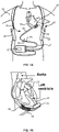
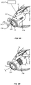
- FIG. 1 is an illustration of a mechanical circulatory support system 10 (e.g., a heart or blood pump system) implanted in a patient's body 12.
- the mechanical circulatory support system 10 comprises an implantable heart or blood pump 14, ventricular cuff 16, outflow cannula 18, system controller 20, and power sources 22.
- the implantable blood pump 14 may comprise a VAD that is attached to an apex of the left ventricle, as illustrated, or the right ventricle, or two or more VADS attached to both ventricles of the heart 24.
- the VAD may comprise a centrifugal (as shown) or axial flow pump that is capable of pumping the entire output delivered to the left ventricle from the pulmonary circulation (i.e., up to 10 liters per minute).
- the blood pump 14 may be attached to the heart 24 via the ventricular cuff 16 which is sewn to the heart 24 and coupled to the blood pump 14.
- One end of the blood pump 14 may include an inflow conduit or cannula 31 configured to extend into the ventricle via a cored opening in the heart.
- the other end of the blood pump 14 connects to the ascending aorta via the outflow cannula 18 so that the VAD effectively diverts blood from the weakened ventricle and propels it to the aorta for circulation to the rest of the patient's vascular system.
- FIGS. 1A-1B illustrate the mechanical circulatory support system 10 during battery 22 powered operation.
- a driveline cable 25 (e.g., a percutaneous cable or lead) connects the implanted blood pump 14 to the system controller 20, which monitors system 10 operation.
- the driveline cable 25 may include a percutaneous portion 26 that exits the patient through an exit site 29 (e.g., abdominal aperture) and terminates at in-line connector 28 that connects the percutaneous portion 26 with a modular external cable 27, the other end of the modular external cable 24 being protected within the system controller 20.
- the system controller 20 monitors system operations. Related controller systems applicable to the present invention are described in greater detail below and in U.S. Patent Nos. 5,888,242 , 6,991,595 , 8,323,174 , 8,449,444 , 8,506,471 , 8,597,350 , and 8,657,733 and U.S. Patent Publication Nos. 2005/0071001 and 2013/0314047 .
- the system may be powered by either one, two, or more batteries 22 or other suitable power sources.
- a medical system 200 for capturing and removing particulates or other thrombi during heart pump implantation includes a removable particulate capture device 202 configured to be temporarily deployed within a patient's heart.
- the capture device 202 may be deployed within a left or right ventricle of a patient prior to a coring procedure.
- an opening may be cored through a patient's heart tissue (e.g., myocardium; FIG. 6C ).
- An inflow cannula of a heart pump (e.g., inflow cannula 31) may then be inserted through the cored opening into the ventricle.
- the capture device 202 may be configured to capture particulates released during such a coring procedure. The capture device 202 may then be withdrawn or removed to remove the particulates after the coring procedure or prior to insertion of the inflow cannula into the ventricle.
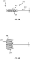
- the capture device 202 includes an expandable basket 204.
- the expandable basket 204 may be constructed out of nitinol or other suitable material.
- the basket 204 may be a mesh basket (e.g., constructed from a wire mesh, woven material, sheet with laser-cut holes).
- the expandable basket 204 is movable between collapsed ( FIG. 2A ) and expanded ( FIG. 2B ) configurations.
- the expandable basket 204 may be moved to the collapsed configuration during delivery into or removal from the patient's heart.
- the expandable basket 204 may be smaller or contracted longitudinally or radially in the collapsed configuration relative to the expanded configuration.
- the expandable basket 204 is smaller radially but larger longitudinally (e.g., longer) in the collapsed configuration relative to the expanded configuration.
- the expandable basket 204 may be moved to the expanded configuration when deployed within the patient's heart to capture particulates released during or throughout the coring procedure. After the coring procedure is completed (e.g., the core has been removed) or prior to implantation of the inflow cannula, the expandable basket 204 may be moved or returned to the collapsed configuration for removal from the patient (e.g., to remove the captured particulates).
- the expandable basket 204 may be removed in the expanded configuration from the heart (e.g., through a cored opening in heart tissue).
- the expandable basket 204 may include a visual indicator (e.g., light, exposed radiopaque marker, color) to indicated to a clinician that the expandable basket 204 is in the expanded configuration and ready to capture particulates.
- the expandable basket 204 includes a plurality of elastically deformable (e.g., nitinol) structural frame members 206 (e.g., struts, links) configured to allow the expandable basket 204 to move between the collapsed and expanded configurations.
- the expandable basket 204 may be configured to self-expand from the collapsed configuration to the expanded configuration when deployed within the patient's heart.
- the structural frame members 206 may be constructed from a shape-memory material. When inserted into the patient's heart, the structural frame members 206 may move the expandable basket 204 to the expanded configuration as the structural frame members 206 are exposed to a higher temperature (e.g., internal temperature of the patient).
- shape-memory structural frame members 206 may be configured to self-expand to move the expandable basket 204 from the collapsed configuration to the expanded configuration.
- the expandable basket 204 may be delivered via a delivery tube or outer sheath in a collapsed configuration and move to the expandable configuration when released from the outer sheath (e.g., remove a force maintaining the basket 204 in the collapsed configuration during delivery).
- the basket 204 may also be moved or returned to the collapsed configuration from the expanded configuration as described in more detail below.
- the expandable basket 204 is configured to expand until the structural frame members 206 push against inner walls of the patient's heart (e.g., ventricle) to secure the expandable basket 204 in position within the patient's heart in the expanded configuration.
- the expandable basket 204 excludes any additional anchors as the expandable basket 204 is configured to be removable as discussed above.
- the expandable basket 204 may include additional anchors configured to temporarily secure the expandable basket 204 in position within the patient's heart until it is ready to be removed.
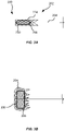
- the capture device 202 includes a deployment mechanism configured to move the expandable basket 204 between collapsed and expanded configurations.
- the capture device 202 may include an actuator 208.
- the actuator 208 includes an inflatable balloon 230 operably coupled to or integrated with the expandable basket 204.
- the inflatable balloon 230 is configured to move the expandable basket 204 to the expanded configuration when inflated.
- the inflatable balloon may move the expandable basket 204 to the collapsed configuration when deflated.
- the expandable basket 204 is configured to move to the expanded configuration when the balloon is inflated and remain in the expanded configuration after the balloon is deflated.
- the balloon 230 may extend longitudinally along the expandable basket or delivery shaft as illustrated in FIG. 3A . In other embodiments, the balloon 230 may extend around the expandable basket circumferentially (e.g., along an inner diameter of the expandable basket).
- the actuator 208 may include a movable (e.g., axially slidable) runner or hub 233.
- the hub 233 may be coupled to a delivery shaft 234 (e.g., as described in more detail below with respect to delivery mechanism 232 and FIGS. 5A-5B ).
- the delivery shaft 234 may be coupled to the expandable basket 204.
- the capture device 202 may include a plurality of support ribs or members 236 (e.g., extenders or stretcher) configured to expand or collapse the structural frame members 206 of the expandable basket 234. First ends (e.g., proximal ends) of the support members 236 may be coupled to the hub 233.
- Second ends (e.g., distal ends) of the support members 236 may be coupled to the structural frame members 206.
- the hub 233 may be movable in a first direction (e.g., proximally) along the delivery shaft 234 to pull the structural frame members 206 radially inward via the support members 236 (e.g., to collapse the expandable basket 204).
- the hub 233 may be movable in a second direction (e.g., distally) along the delivery shaft 234 to push the structural frame members 206 radially outward (e.g., to expand the expandable basket 204).
- the expandable basket 204 may be moved to the expanded configuration to capture particulates released during a heart coring procedure. Openings between the structural frame members 206 may be sized to capture such particulates (e.g., the particulates having a size of about 200 ⁇ m or smaller, about 150 ⁇ m or smaller, about 100 ⁇ m or smaller, about 50 ⁇ m or smaller, about 10 ⁇ m or smaller, about 5 ⁇ m or smaller, about 2 ⁇ m or smaller, between about 2 ⁇ m to about 200 ⁇ m, between about 2 ⁇ m to about 150 ⁇ m, between about 2 ⁇ m to about 100 ⁇ m, between about 2 ⁇ m to about 50 ⁇ m, between about 2 ⁇ m to about 10 ⁇ m, between about 2 ⁇ m to about 5 ⁇ m, or any value therebetween).
- the particulates having a size of about 200 ⁇ m or smaller, about 150 ⁇ m or smaller, about 100 ⁇ m or smaller, about 50 ⁇ m or smaller, about 10 ⁇ m or smaller, about 5
- the expandable basket 204 may also include a mesh membrane, liner, or cover layer 238 (e.g., a polymer mesh) over at least a portion of the structural frame members 206 to capture the particulates.
- a mesh membrane, liner, or cover layer 238 e.g., a polymer mesh
- openings in the mesh cover layer 238 may be sized to capture such particulates (e.g., about 100 ⁇ m or smaller).
- the openings between the structural frame members 206 or mesh cover layer 238 are sized such that little to no fluid (e.g., blood) may flow through or past the expandable basket 204 when positioned in the patient's heart. As described in more detail below ( FIGS.
- the patient may be coupled to a cardiopulmonary bypass machine such that blood bypasses the heart chambers and does need to flow through the expandable basket 204
- the openings between the structural frame members 206 or mesh cover layer 238 are sized such that fluid (e.g., blood) may flow through or past the expandable basket 204 when positioned in the patient's heart (e.g., such that the expandable basket 204 may be removed after a coring procedure with the captured particulates but without also removing a substantial amount of blood from the patient's heart).
- fluid e.g., blood
- the cardiopulmonary bypass machine when the cardiopulmonary bypass machine is in an off-position as described in more detail below, blood may flow or be pumped out the heart to remove such particulates.
- the openings may be sized to allow blood or other fluid to flow through the expandable basket 204.
- the medical system 200 includes a delivery mechanism 232 configured to deliver or insert as well as withdraw or remove the capture device 202.
- the delivery mechanism may include the delivery shaft 234 (e.g., sheath, catheter, sleeve, lumen, tube, conduit) coupled to the expandable basket 204.
- the delivery shaft 234 is configured to be non-detachable from the expandable basket 204 as the expandable basket 204 is configured to be removed after particulates are captured or before the inflow cannula is inserted.
- the delivery shaft 234 may be configured to be detachable to deploy the expandable basket 204 in the heart to capture particulates and re-attachable to remove the expandable basket 204 once the coring procedure is completed or prior to installation of the inflow cannula.
- the delivery mechanism 232 is a catheter-type delivery system.
- the delivery shaft 234 may include a distal end portion coupled to the expandable basket 204 and a proximal end portion coupled to one or more catheter handles (e.g., a first catheter handle 240) with controls for steering, moving, actuating, locking or rotating associated delivery shafts or conduits).
- the delivery mechanism 220 includes one or more guidewires to aid in positioning or inserting the capture device 202 in the patient's heart.
- the delivery mechanism 220 may include an outer sheath 242 (e.g., shaft, catheter, sleeve, lumen, tube, conduit) or guide catheter coupled to the first catheter handle or to a separate second catheter handle.
- the outer sheath 242 is configured to extend around at least a portion of the delivery shaft 234.
- the delivery shaft 234 may be guided or positioned in the patient's heart via or along with the outer sheath 242.
- the delivery shaft 234 is movable relative to the outer sheath 242 (e.g., may be pushed distally out of the outer sheath 242) to deploy the expandable basket 204 out of the outer sheath 242 and into the patient's heart.
- the outer sheath 242 is movable relative to the delivery shaft 234 (e.g., may be moved or slid proximally) to deploy the expandable basket 204 out of the outer sheath 242 and into the patient's heart.
- the delivery shaft 234 and outer sheath 242 are both movable relative to each other.
- the expandable basket 204 may include elastically deformable structural frame members 206 such that it may self-expand (e.g., automatically) to the expanded configuration as it is deployed out of or released from the outer sheath 242.
- the expandable basket 204 may be stowed or maintained (e.g., constrained) in the collapsed configuration by the outer sheath 242 (e.g., or other intermediary sheaths as described below) until it is deployed or released into the heart.
- the delivery mechanism 232 may include a sharpened distal tip 244.
- a distal tip of the outer sheath 242 or delivery shaft 234 may be provided with a blade or sharpened edge to cut through heart tissue when inserting the capture device 202 into the heart or make an incision that the capture device 202 may be inserted through into the heart.
- the delivery mechanism 220 may include an atraumatic or blunt distal tip. In such embodiments, an access site or incision through the heart tissue of the patient may be created prior to inserting the capture device 202.
- the delivery mechanism 220 includes one or more intermediary or additional shafts or sheaths (e.g., catheters, sleeves, lumens, tubes, conduits, guidewires) between the delivery shaft 234 and the outer sheath 242, within or extending through the delivery shaft, or surrounding at least a portion of the outer sheath 242 (e.g., delivery or guide catheter or sheath).
- intermediary or additional sheaths may be configured to help guide or deploy the expandable basket 204.
- additional sheaths may be configured as a pusher to push the expandable basket 204 or delivery shaft 234 out of the outer sheath 242, provide pathways for fluids (e.g., for suction or aspiration, inflating a balloon 230 or actuating a hub 233 as described above, or for irrigation as described in more detail below), or for moving an actuator (e.g., hub 233) to expand or collapse the expandable basket 204.
- the delivery shaft 234, outer sheath 242, or one or more intermediary sheaths may have a non-coaxial or non-concentric configuration.
- the outer sheath 242 may include a plurality of lumens off-set from a center of the outer sheath 242 and configured to receive the delivery shaft 242 or one or more intermediary sheaths.
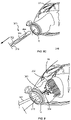
- FIGS. 6A-6E illustrate a series of views of an exemplary heart pump implantation procedure or process including insertion and removal of the capture device 202.
- Implantation of the blood pump 14 to the heart 24 may include selecting a location to attach the ventricular cuff 16.
- an apex 229 of the left ventricle may be selected as an operation site.
- the ventricular cuff 16 may be positioned in contact with the selected operation site. Methods do not form part of the claimed subject matter.
- the ventricular cuff 16 may then be sewn or otherwise attached to the heart 24.
- the capture device 202 may then be inserted into the heart 24 through an opening 246 defined by the ventricular cuff 16 configured to receive the inflow cannula 31 of the blood pump 14.
- the delivery shaft 234 or outer sheath 242 may include a sharpened distal tip 244 configured to puncture the heart tissue such that the expandable basket 204 may be inserted into the heart 24.
- an access site or incision may be made through the heart tissue by a separate tool prior to inserting the capture device 202.
- the access site may be a site created for coring the heart or another separate access site.
- the expandable basket 204 may be inserted or otherwise delivered into the heart 24 in the collapsed configuration via the delivery mechanism 232. Once the expandable basket 204 is in a desired position (e.g., in the left ventricle), the expandable basket 204 may be moved to the expanded configuration ( FIG. 6B ). As described above, the expandable basket 204 may self-expand as it is deployed or released from the outer sheath 242 or include an actuator 208 to move the expandable basket 204 to the expanded configuration. The outer sheath 242 may then be removed from the patient if the delivery mechanism 220 includes an outer sheath.
- an opening or hole 248 in the heart tissue may then be formed by a coring procedure performed upon the portion of the heart defined by the opening 246 in the ventricular cuff 16.
- a clinician may use a surgical coring tool 250 (e.g., a coring knife) or other suitable knife to core or remove the portion of the heart (e.g., heart tissue at apex 229 including myocardium) of FIG. 6B .
- the expandable basket 204 is configured to capture released particulates.
- the expandable basket 204 includes a cavity or concave opening oriented or facing the cored opening or opening to be cored to capture the released particulates.
- the expandable basket 204 may be removed or withdrawn from the heart ( FIG. 6D ).
- the expandable basket 204 is moved to the collapsed configuration from the expanded configuration and then withdrawn to remove the captured particulates.
- the expandable basket 204 is withdrawn or removed with the captured particulates directly in the expanded configuration.
- the delivery shaft 234 is detachable from the expandable basket 204, the delivery shaft 234 is detached after the expandable basket 204 is deployed to capture particulates and re-attached for removal of the expandable basket 204 after the coring procedure is completed.
- particulates may be removed manually by a clinician (e.g., with tweezers), by suction (e.g., via an aspiration conduit), or deactivating a cardiopulmonary bypass machine as described in more detail below.
- the inflow cannula 31 of the blood pump 14 may be inserted into heart opening 248 through the ventricular cuff 16 and the blood pump 14 may be coupled to the ventricular cuff 16.
- the ventricular cuff 16 will be first attached to the heart 24 and then heart tissue will be removed or cored (e.g., core section of heart tissue removed through the cuff 16) to insert the inflow cannula 31 as described above.
- heart tissue may also be removed or cored prior to attaching the ventricular cuff 16 to the heart 24.
- the capture device 202 may be inserted or removed prior to attaching the ventricular cuff 16.
- the expandable basket 204 may be inserted into the heart prior to a coring procedure.
- the cuff 16 may then be attached after the coring procedure.
- the basket 204 may be removed prior to or after attaching the cuff 16.
- Related ventricular cuffs and attachment and coring procedures applicable to the present invention are described in U.S. Patent Publication Nos. 2015/0273124 .
- the patient e.g., veins and arteries near the heart 24
- the bypass machine 252 may be activated (e.g., in an on position) such that blood bypasses the heart chambers and does not circulate through the heart or deactivated (e.g., in an off position) such that blood circulates through the heart as necessary during the implantation process.
- the bypass machine 252 is activated until the heart pump implantation process is complete.
- the bypass machine may be deactivated at times (e.g., temporarily or periodically) to allow blood to circulate through the heart as necessary.
- the heart pump implantation process may be completed (e.g., the ventricular cuff 16 can be coupled to the heart 24 and heart tissue cored and removed) in the absence of a bypass machine 252.
- the surgical coring tool 250 (e.g., a coring knife) may be used to core a portion of the heart during heart pump implantation.
- the delivery mechanism 220 or capture device 202 is integrated with the surgical coring tool 250.
- a body or shaft of the surgical coring tool 250 may include a lumen 251.
- the delivery mechanism 220 or capture device 202 (e.g., delivery shaft 234 or expandable basket 204) may be configured to extend through such a lumen to be deployed into the patient's heart prior to coring by the surgical coring tool 250.
- the capture device 202 or delivery mechanism 220 may be integrated with a tissue irrigating device as described herein.
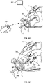
- a medical system 300 for irrigating or rinsing away particulates or other thrombi during heart pump implantation may include a removable irrigation device 360 configured to be temporarily deployed within a patient's heart.
- the irrigation device 360 may be deployed within a left or right ventricle of a patient after a coring procedure to irrigate the cored opening or ventricle after the core has been removed.
- the irrigation device 360 may then be withdrawn or removed prior to implantation of the blood pump (e.g., insertion of the inflow cannula into the ventricle).
- the irrigation device 360 may be deployed within the cored opening or section of the heart (e.g., within the cored opening in the myocardium), a ventricle, or both the cored opening and ventricle. In other embodiments, in addition to, or alternatively, the irrigation device 360 may be deployed or positioned proximate to, over, or outside a cored opening of the heart to irrigate, flush, or rinse away particulates (e.g., near an edge or periphery of the cored opening).
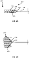
- the irrigation device 360 includes a delivery tube 362 (e.g., catheter, sleeve, lumen, tube, conduit) and one or more irrigation conduits 364 (e.g., 2, 3, 4, 5) extending therethrough.
- the irrigation conduits 364 may be movable between stowed or stored positions and deployed positions. In the stored positions ( FIG. 7A ), the irrigation conduits 364 are positioned substantially within the delivery tube 362. In the deployed positions ( FIG. 7B ), the irrigation conduits 364 are configured to extend or protrude out of openings 366 in the delivery tube 362.
- the irrigation conduits 364 are configured to disperse fluid into a cored opening or other portion of the heart (e.g., ventricle) for irrigating or rinsing away particulates when in the deployed positions within the patient's heart.
- the irrigation conduits 364 may be moved to the stored or stowed positions for delivery or removal (e.g., in a more compact configuration).
- the irrigation conduits 364 may be directly inserted into the patient's heart to disperse fluid (e.g., without a delivery tube).
- one or more irrigation conduits may be disposed or positioned directly in a portion of the patient's heart to irrigate particulates.
- the delivery tube 362 functions as the irrigation conduit without additional conduits 364 extending therethrough (e.g., openings to disperse fluid as described in more detail below are disposed on the delivery tube 362).
- the irrigation conduits 364 are entirely stowed within the delivery tube 362 when in the stored position.
- the irrigation device 360 includes a fluid source 368 operably connectable or coupleable to the irrigation conduits 364 to deliver irrigating fluid.
- the irrigation conduits 364 may be coupled to a saline solution filled drip bag, syringe, pump or other suitable fluid source.
- each of the irrigation conduits 364 are coupled to a single fluid source 368.
- proximal ends of the irrigation conduits 364 may be coupled to or funneled into a single conduit in fluid communication with the fluid source 368.
- the irrigation conduits 364 are coupled to two or more or separate fluid sources.
- Distal end portions of the irrigation conduits 364 configured to protrude out of the delivery tube 362 through the openings 366 when in the deployed position may include a plurality of holes 370.
- the irrigation conduits 364 may include two or more, three or more, four or more, or five or more openings 366. Fluid (e.g., from fluid source 368) may flow or spray out of the holes 370 to irrigate the patient's heart.
- distal tips or ends of the irrigation conduits 364 include plugs 371, are crimped, or are otherwise closed-ended. By closing ends of the irrigation conduits 364, increased fluid pressure may be directed out of the holes 370.
- the irrigation conduits 364 are configured to be flexible or bendable (e.g., elastically deformable) or include atraumatic tips such as to prevent or reduce a likelihood of damage to or catching on portions of the heart as the irrigation conduits 364 are moved between the stored and deployed positions and/or when the irrigation device 360 is inserted or withdrawn,
- distal portions of the irrigation conduits 364 e.g., portions configured to protrude out of the delivery tube 362 and into the heart
- the openings 366 in the delivery tube 362 that the irrigation conduits 364 are configured to extend out of in the deployed positions may be spaced apart from a distal tip or end of the delivery tube.
- the openings 366 may be located or extend through sidewalls (e.g., outer side surfaces) of the delivery tube 362.
- the irrigation conduits 364 may extend out of one or more openings 366 at a distal tip or end of the delivery tube 362 in the deployed positions.
- the irrigation conduits 364 may extend in a substantially non-arcuate manner out of the openings 366 in the delivery tube (e.g., at oblique or non-oblique angles). In some embodiments, the irrigation conduits 364 extend out of the openings 366 at a suitable angle to irrigate the particulates (e.g., between about 90 degrees to about 120 degrees, between about 120 degrees to about 150 degrees, between about 150 degrees to about 180 degrees, or any value therebetween).
- the delivery tube 362 includes an atraumatic or blunt distal tip as the irrigation device 360 may be configured to be positioned in the heart through a cored opening. Such an atraumatic tip may also prevent or reduce a likelihood of damage to the heart as the delivery tube 362 is inserted or removed as described in more detail below.
- FIGS. 8A-8C illustrate a series of views of an exemplary heart pump implantation procedure or process including insertion and removal of the irrigation device 360.
- the heart pump implantation procedure may include one or more of any of the steps described above and illustrated in FIGS. 6A-6E (e.g., selecting an operation site, attaching the ventricular cuff 16, inserting or removing a capture device, coring a portion of the heart).
- the irrigation device 360 may be delivered or inserted into the heart (e.g., ventricle, cored opening in myocardium, or both) through the cored opening 348 in the stored position.
- the irrigation device 360 may be inserted through an opening defined by the ventricular cuff 16 through the cored opening when the ventricular cuff 16 is attached to the heart prior to the coring procedure. In other embodiments, the irrigation device 360 may be inserted prior to a coring procedure.
- the irrigation device 360 is integrated with the surgical coring 350 tool, the capture device 202, or both the surgical coring tool 350 and the capture device 202 as described in more detail below.
- the irrigation conduits 364 may be moved to the deployed positions and extend out of openings 366 in the delivery tube 362.
- the proximal ends of the irrigation conduits 364 or delivery tube 362 may be operatively coupled to one or more catheter handles 240 with controls for extending and retracting the delivery tube 362 or irrigation conduits 364.
- a pusher shaft 373 e.g., a delivery shaft
- the pusher shaft is coupled to the irrigation conduits 364 such that they can be extended or retracted simultaneously from the delivery tube 362 (e.g., by moving the pusher shaft axially in a distal or proximal within the delivery tube 362).
- the irrigation conduits 364 may be moved between the stored and deployed positions independently or separately from each other.
- each of the conduits 364 may be coupled to separate pusher shafts.
- each of the conduits 364 may be coupled to the catheter handle or moved directly.
- the conduits 364 may taper or funnel into a single conduit or shaft (e.g., at a proximal end).
- the irrigation conduits 364 are configured to disperse fluid from the fluid source 368 into the patient's heart to irrigate the heart (e.g., ventricle walls, heart, cored opening walls).
- a patient may be coupled to a cardiopulmonary bypass machine during at least a portion of the heart pump implantation process. While the bypass machine is generally activated until the heart pump implantation process is complete, the bypass machine may be deactivated at times (e.g., temporarily or periodically) to allow blood to circulate through the heart. As such, the bypass machine may be deactivated after dispersing fluid with the irrigation device 360 to push or remove particulates out of the heart (e.g., allow blood with any loose particulates to be pumped out of the cored opening). In some embodiments, a clinician may alternate or cycle between dispersing fluid and deactivating the bypass machine multiple times while the irrigation device 360 is deployed within the heart.
- a delivery tube 362 may include a suction or aspiration lumen or conduit to aspire loose particulates released by irrigating with the irrigation device 360.
- the irrigation device 360 may be integrated with the capture device 202 as described in more detail below to remove irrigated particulates.
- the irrigation device 360 may be removed or withdrawn from the heart.
- the irrigation conduits 364 are moved to the stored positions within the delivery tube 362 (e.g., by moving the pusher shaft 373 proximally) and the delivery tube 362 is removed from the patient through the cored opening.
- the heart pump or inflow cannula may then be implanted or attached as described above.
- the delivery tube 362 may be removed or withdrawn from the heart through the cored opening without moving the irrigation conduits 364 to the stored positions prior to installing the heart pump or inflow cannula.
- the irrigation device 360 as described herein may be integrated with the surgical coring tool 350.
- a body or shaft of the surgical coring tool 350 may include a lumen 351.
- the delivery tube 362 or capture device 202 e.g., irrigation conduits 364 may be configured to extend through such a lumen to be deployed into the patient's heart (e.g., after coring by the surgical coring tool 350).
- the lumen of the coring tool 350 may serve as a housing or delivery tube the irrigation conduits 364 may be stowed in the stored positions without the delivery tube 362. In the deployed positions, the irrigation conduits 364 may extend out of sidewall openings in the shaft of the coring tool 350.
- the delivery tube 362 may extend through the lumen of the coring tool 350 with the irrigation conduits stowed within.
- FIG. 9 illustrates an embodiment of a medical system 400 including both the capture device 202 and irrigation device 360 as described above.
- the irrigation device 360 may be configured to be deployed or work in conjunction with the capture device 202.
- the capture device 202 may be inserted into the patient's heart and capture particulates released by the coring procedure and that are irrigated by the tissue irrigating device 360.
- the capture device 202 may be inserted and deployed within the patient's heart prior to a coring procedure.
- the irrigation device 360 may then be delivered and deployed through the cored opening after the coring procedure to irrigate the cored opening or heart.
- the irrigation device 360 may be integrated with the capture device 202.
- the capture device 202 and tissue irrigating device 360 may share an outer sheath or delivery tube (e.g., delivery tube 362, outer sheath 242).
- the capture device 202 and tissue irrigating device 360 may be delivered in their stored or collapsed configurations into the heart via the shared delivery tube (e.g., prior to a coring procedure).
- the irrigation conduits 364 and the expandable basket 204 may then be moved to the deployed or expanded configurations when positioned in the heart.
- the devices 202, 360 may additionally share a pusher or delivery shaft (e.g., pusher shaft 373, delivery shaft 234) coupled to the irrigation conduits 364 and expandable basket 204.
- a pusher or delivery shaft e.g., pusher shaft 373, delivery shaft 234
- both the capture device 202 and irrigation device 360 may be integrated with a surgical coring tool (e.g., surgical coring tools 250, 350).
- a surgical coring tool e.g., surgical coring tools 250, 350
- the lumen of the surgical coring tool may serve as an outer sheath or delivery tube.
- the capture device 202 and irrigation device 360 may be configured to extend through the lumen of the coring tool.
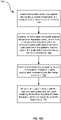
- FIGS. 10A-10C are a series of flowcharts illustrating exemplary methods 500, 600, and 700 for capturing and removing particulates, irrigating particulates, and irrigating, capturing, and removing particulates, respectively, with any of the systems and devices as described herein during heart pump implantation.
- One or more of any steps of methods 500-700 as described herein may be included, combined, or substituted within any of the other methods. Further, steps may be removed, re-ordered, substituted, or added. Methods do not form part of the claimed subject matter.
- exemplary method 500 for capturing particulates during heart pump implantation may include inserting a removable particulate capture device (e.g., capture device 202) as described herein into a patient's heart prior to a coring procedure upon the patient's heart 580.
- the method may include inserting a delivery or guide tube or catheter housing the expandable basket in a collapsed configuration into the patient's heart.
- the removable particulate capture device includes an expandable basket (e.g., expandable basket 204) movable between collapsed and expanded configurations.
- the method 500 further includes expanding the expandable basket to the expanded configuration from the collapsed configuration when the removable particulate capture device is positioned within the patient's heart to capture the particulates released during the coring procedure 581.
- the expandable basket may include self-expanding structural frame members or the method may include inflating a balloon or moving an actuator to expand the expandable basket.
- the method 500 may include expanding the expandable basket until it contacts walls of a ventricle (e.g., the left ventricle).
- the method 500 includes removing the expandable basket with the captured particulates from the patient's heart through a cored opening 582.
- the method 500 may include collapsing the expandable basket to the collapsed configuration from the expanded configuration after the coring procedure and prior to removing the expandable basket from the patient's heart. In some embodiments, the method 500 includes collapsing the expandable basket to the collapsed configuration from the expanded configuration prior to inserting the removable particulate capture device into the patient's heart.
- the method 500 may include creating an access site through a surface of the patient's heart that the removable particulate capture device can be inserted through into the patient's heart.
- the method 500 may include coring a portion of the patient's heart after inserting the removable particulate capture device within the patient's heart.
- the method 500 may include inserting a removable tissue irrigating device (e.g., irrigating device 360) into the patient's heart configured to irrigate particulates released during the coring procedure after coring the portion of the patient's heart.
- a removable tissue irrigating device e.g., irrigating device 360
- the method 500 may include attaching a ventricular cuff or inflow cannula of a VAD to the heart.
- exemplary method 600 for irrigating particulates during heart pump implantation may include inserting a removable tissue irrigating device (e.g., irrigating device 360) into a patient's heart (e.g., a left ventricle) through the patient's heart tissue to irrigate particulates released during a coring procedure 685.
- the removable tissue irrigating device includes a delivery tube and at least one irrigation conduit extending therethrough.
- the method 600 includes extending the irrigation conduit out of an opening in the delivery tube to a deployed position from a stored position 686.
- the irrigation conduit is substantially positioned within the delivery tube in the stored position.
- the irrigation conduit includes a distal portion extending out of the delivery tube in the deployed position.
- the method 600 includes dispersing fluid from the irrigation conduit into the patient's heart 687.
- the method 600 further includes removing the removable tissue irrigating device from the patient's heart 688 (e.g., prior to, after, or concurrently with removing the released particulates).
- the method may include removing the particulates released by the coring procedure or disperse fluid as described herein.
- the method 600 may include coring a portion of the patient's heart tissue prior to inserting the removable tissue irrigating device into the patient's heart.
- the method 600 may include inserting the removable tissue irrigating device into the patient's heart through a cored opening in the patient's heart tissue.
- the method 600 includes inserting a removable particulate capture device (e.g., capture device 202) into the patient's heart configured to capture and remove irrigated or released particulates.
- the removable particulate capture device may be inserted prior to a coring procedure.
- the method 600 includes temporarily switching a cardiopulmonary bypass machine coupled to the patient's heart from an on position to an off position to pump irrigated or released particulates out of the heart.
- an aspiration catheter is used to suction out the particulates.
- a clinician may remove the particulates with tweezer or other suitable tools.
- exemplary method 700 for irrigating, capturing, and removing particulates during heart pump implantation may include inserting a removable particulate capture device (e.g., capture device 202) as described herein into a patient's heart prior to a coring procedure upon the patient's heart 790.
- the method 700 includes expanding the removable particulate capture device to an expanded configuration from a collapsed configuration when the removable particulate capture device is positioned within the patient's heart to capture the particulates released during the coring procedure 791.
- the method includes inserting a removable tissue irrigating device (e.g., irrigating device 360) into the patient's heart to irrigate particulates released during the coring procedure 792.
- the method 700 includes removing the capture device with the captured particulates and the tissue irrigating device from the patient's heart through a cored opening in the patient's heart tissue 793.
Claims (15)
- Medizinisches System (200) zum Fangen und Entfernen von Partikeln während der Herzpumpenimplantierung, wobei das medizinische System (200) Folgendes umfasst:eine entfernbare Partikelfangvorrichtung (202), die dazu ausgestaltet ist, vor einem Ausstanzvorgang in dem Herz eines Patienten ausgebracht zu werden, um während und/oder nach dem Ausstanzvorgang freigesetzte Partikel zu fangen und zu entfernen, wobei die entfernbare Partikelfangvorrichtung (202) einen expandierbaren Korb (204) umfasst, wobei der expandierbare Korb (204) zwischen einer zusammengefalteten Konfiguration und einer expandierten Konfiguration beweglich ist, wobei der expandierbare Korb (204) dazu ausgestaltet ist, Innenwände einer linken Herzkammer des Herzes des Patienten zu kontaktieren, wenn er in der expandierten Konfiguration ist, um den expandierbaren Korb (204) während des Ausstanzvorgangs in Position in der linken Herzkammer zu befestigen, wobei der expandierbare Korb (204) dazu ausgestaltet ist, während der Zuführung in das Herz des Patienten in der zusammengefalteten Konfiguration zu sein und beim Ablegen im Herz des Patienten in der expandierten Konfiguration, um während des und/oder nach dem Ausstanzvorgang(s) am Herz des Patienten freigesetzte Partikel zu fangen, undeinen Zuführungsmechanismus (232), der einen Zuführungsschaft (234) mit einem proximalen Endabschnitt und einem distalen Endabschnitt umfasst, wobei der distale Endabschnitt an den expandierbaren Korb (204) gekoppelt ist und wobei der Zuführungsmechanismus (232) eine Klinge oder eine scharfe Kante (244) umfasst, die dazu ausgestaltet ist, eine Inzision im Herz des Patienten vorzunehmen, durch die die entfernbare Partikelfangvorrichtung (202) in die linke Herzkammer des Herzes des Patienten eingeführt wird.
- Medizinisches System (200) nach Anspruch 1, wobei eine distale Spitze des Zuführungsschafts (234) mit der Klinge oder der scharfen Kante (244) versehen ist.
- Medizinisches System (200) nach Anspruch 1, wobei der Zuführungsschaft (234) von dem expandierbaren Korb (204) ablösbar und nach dem Abschluss des Ausstanzvorgangs wieder an dem expandierbaren Korb (204) anbringbar ist, um den expandierbaren Korb (204) aus der linken Herzkammer zu entfernen.
- Medizinisches System (200) nach Anspruch 1, wobei der Zuführungsmechanismus (232) eine äußere Hülse (242) umfasst, die sich um mindestens einen Abschnitt des Zuführungsschafts (234) erstreckt, und
wobei der Zuführungsschaft (234) bezüglich der äußeren Hülse (242) beweglich ist, um den expandierbaren Korb (204) aus der äußeren Hülse (242) in die linke Herzkammer des Herzes des Patienten auszubringen. - Medizinisches System (200) nach Anspruch 4, wobei eine distale Spitze der äußeren Hülse (242) mit einer Klinge oder einer scharfen Kante (244) versehen ist.
- Medizinisches System (200) nach Anspruch 1, wobei der Zuführungsmechanismus (232) mit einem chirurgischen Ausstanzwerkzeug (250) integriert ist, das ein Lumen (251) umfasst, wobei die entfernbare Partikelfangvorrichtung (202) dazu ausgestaltet ist, durch das Lumen (251) vorgeschoben zu werden, so dass die entfernbare Partikelfangvorrichtung (202) vor dem Ausstanzvorgang in die linke Herzkammer eindringt, und wobei das chirurgische Ausstanzwerkzeug (250) zur Verwendung bei der Durchführung des Ausstanzvorgangs ausgestaltet ist.
- Medizinisches System (200) nach einem der Ansprüche 1 - 6, ferner umfassend eine entfernbare Gewebespülungsvorrichtung, die dazu ausgestaltet ist, während des und/oder nach dem Ausstanzvorgang(s) freigesetzte Partikel aus dem Herz des Patienten zu spülen.
- Medizinisches System (200) nach einem der Ansprüche 1 - 7, wobei der expandierbare Korb (204) dazu ausgestaltet ist, sich selbst aus der zusammengefalteten Konfiguration in die expandierte Konfiguration zu expandieren, wenn er in dem Herz des Patienten ausgebracht wird.
- Medizinisches System (200) nach einem der Ansprüche 1 - 7, wobei der expandierbare Korb (204) eine Vielzahl von Strukturrahmengliedern (206) umfasst, wobei die Strukturrahmenglieder (206) proximale und distale Enden haben, wobei die distalen Enden an den Zuführungsschaft (234) gekoppelt sind.
- Medizinisches System (200) nach Anspruch 9, wobei die Vielzahl von Strukturrahmengliedern (206) elastisch deformierbar sind.
- Medizinisches System (200) nach Anspruch 1, wobei der expandierbare Korb (204) in der expandierten Konfiguration einen Hohlraum oder eine konkave Öffnung aufweist, der bzw. die der auszustanzenden Öffnung zugewandt ist, um während des Ausstanzvorgangs freigesetzte Partikel zu fangen.
- Medizinisches System (200) nach Anspruch 9, ferner umfassend einen Aktuator (208), der dazu ausgestaltet ist, den expandierbaren Korb (204) aus der zusammengefalteten Konfiguration in die expandierte Konfiguration zu bewegen.
- Medizinisches System (200) nach Anspruch 12, wobei der Aktuator (208) einen inflatierbaren Ballon (230) umfasst, der dazu ausgestaltet ist, den expandierbaren Korb (204) in die expandierte Konfiguration zu bewegen, wenn er inflatiert wird, und in die zusammengefaltete Konfiguration, wenn er deflatiert wird.
- Medizinisches System (200) nach Anspruch 12, ferner umfassend eine Vielzahl von Stützgliedern (236) mit proximalen und distalen Enden, wobei die proximalen Enden der Stützglieder (236) an den Aktuator (208) gekoppelt sind und die distalen Enden der Stützglieder (236) an die Strukturrahmenglieder (206) gekoppelt sind, und wobei der Aktuator (208) bezüglich des Zuführungsschafts (234) axial beweglich ist, um den expandierbaren Korb (204) zwischen der zusammengefalteten Konfiguration und der expandierten Konfiguration zu bewegen.
- Medizinisches System (200) nach einem der Ansprüche 9 - 14, wobei die Vielzahl von Strukturrahmengliedern (206) des expandierbaren Korbs (204) so positioniert sind, dass sie eine Vielzahl von Öffnungen zwischen der Vielzahl von Strukturrahmengliedern (206) schaffen, wobei die Öffnungen zum Fangen von Partikeln bemessen sind, wenn der expandierbare Korb (204) in der expandierten Konfiguration ist.
Applications Claiming Priority (2)
| Application Number | Priority Date | Filing Date | Title |
|---|---|---|---|
| US201862648165P | 2018-03-26 | 2018-03-26 | |
| PCT/US2019/023910 WO2019190998A1 (en) | 2018-03-26 | 2019-03-25 | Methods and systems for irrigating and capturing particulates during heart pump implantation |
Publications (2)
| Publication Number | Publication Date |
|---|---|
| EP3773272A1 EP3773272A1 (de) | 2021-02-17 |
| EP3773272B1 true EP3773272B1 (de) | 2022-09-28 |
Family
ID=66102241
Family Applications (1)
| Application Number | Title | Priority Date | Filing Date |
|---|---|---|---|
| EP19716664.8A Active EP3773272B1 (de) | 2018-03-26 | 2019-03-25 | Systeme zum spülen und einfangen von partikeln während der implantation von herzpumpen |
Country Status (3)
| Country | Link |
|---|---|
| US (2) | US11076944B2 (de) |
| EP (1) | EP3773272B1 (de) |
| WO (1) | WO2019190998A1 (de) |
Family Cites Families (40)
| Publication number | Priority date | Publication date | Assignee | Title |
|---|---|---|---|---|
| US5989281A (en) * | 1995-11-07 | 1999-11-23 | Embol-X, Inc. | Cannula with associated filter and methods of use during cardiac surgery |
| US5695471A (en) | 1996-02-20 | 1997-12-09 | Kriton Medical, Inc. | Sealless rotary blood pump with passive magnetic radial bearings and blood immersed axial bearings |
| US5840070A (en) | 1996-02-20 | 1998-11-24 | Kriton Medical, Inc. | Sealless rotary blood pump |
| DE19625300A1 (de) | 1996-06-25 | 1998-01-02 | Guenter Prof Dr Rau | Blutpumpe |
| US6071093A (en) | 1996-10-18 | 2000-06-06 | Abiomed, Inc. | Bearingless blood pump and electronic drive system |
| US5888242A (en) | 1996-11-01 | 1999-03-30 | Nimbus, Inc. | Speed control system for implanted blood pumps |
| US6245088B1 (en) | 1997-07-07 | 2001-06-12 | Samuel R. Lowery | Retrievable umbrella sieve and method of use |
| US6264635B1 (en) | 1998-12-03 | 2001-07-24 | Kriton Medical, Inc. | Active magnetic bearing system for blood pump |
| US6186665B1 (en) | 1999-01-26 | 2001-02-13 | Nimbus, Inc. | Motor rotor bearing assembly for a blood pump |
| US6234772B1 (en) | 1999-04-28 | 2001-05-22 | Kriton Medical, Inc. | Rotary blood pump |
| US6689150B1 (en) | 1999-10-27 | 2004-02-10 | Atritech, Inc. | Filter apparatus for ostium of left atrial appendage |
| US6942672B2 (en) | 2001-10-23 | 2005-09-13 | Vascor, Inc. | Method and apparatus for attaching a conduit to the heart or a blood vessel |
| US6991595B2 (en) | 2002-04-19 | 2006-01-31 | Thoratec Corporation | Adaptive speed control for blood pump |
| US20050071001A1 (en) | 2003-09-30 | 2005-03-31 | Robert Jarvik | Artificial heart power and control system |
| US7604650B2 (en) * | 2003-10-06 | 2009-10-20 | 3F Therapeutics, Inc. | Method and assembly for distal embolic protection |
| CA2583591C (en) * | 2004-10-02 | 2018-10-30 | Christoph Hans Huber | Methods and devices for repair or replacement of heart valves or adjacent tissue without the need for full cardiopulmonary support |
| US8419609B2 (en) | 2005-10-05 | 2013-04-16 | Heartware Inc. | Impeller for a rotary ventricular assist device |
| US7699586B2 (en) | 2004-12-03 | 2010-04-20 | Heartware, Inc. | Wide blade, axial flow pump |
| US20070142923A1 (en) | 2005-11-04 | 2007-06-21 | Ayre Peter J | Control systems for rotary blood pumps |
| JP5155186B2 (ja) | 2006-01-13 | 2013-02-27 | ハートウェア、インコーポレイテッド | 回転式血液ポンプ |
| EP1981414A2 (de) * | 2006-02-08 | 2008-10-22 | VANCE PRODUCTS INCORPORATED d/b/a COOK UROLOGICAL INCORPORATED | Bewässerungsfänger und entfernungsvorrichtung |
| JP5442598B2 (ja) | 2007-04-30 | 2014-03-12 | ハートウェア、インコーポレイテッド | 遠心回転血液ポンプ |
| AU2009210744B2 (en) | 2008-02-08 | 2014-06-12 | Heartware, Inc. | Ventricular assist device for intraventricular placement |
| US8449444B2 (en) | 2009-02-27 | 2013-05-28 | Thoratec Corporation | Blood flow meter |
| JP5681403B2 (ja) | 2010-07-12 | 2015-03-11 | ソーラテック コーポレイション | 遠心式ポンプ装置 |
| JP5977237B2 (ja) | 2010-08-20 | 2016-08-24 | ソーラテック コーポレイション | 埋め込み可能な血液ポンプ |
| JP5577506B2 (ja) | 2010-09-14 | 2014-08-27 | ソーラテック コーポレイション | 遠心式ポンプ装置 |
| EP3020426B1 (de) | 2010-09-24 | 2017-12-27 | Tc1 Llc | Erzeugung eines künstlichen pulses |
| CA2814122A1 (en) | 2010-10-13 | 2012-04-19 | Thoratec Corporation | Pumping blood |
| US8066628B1 (en) | 2010-10-22 | 2011-11-29 | Nupulse, Inc. | Intra-aortic balloon pump and driver |
| WO2012078873A1 (en) | 2010-12-09 | 2012-06-14 | Heartware, Inc. | Controller and power source for implantable blood pump |
| US20120271341A1 (en) * | 2011-04-25 | 2012-10-25 | Hill Alexander J | Method and Apparatus for Treating a Mitral Valve Prolapse and Providing Embolic Protection |
| US8864643B2 (en) | 2011-10-13 | 2014-10-21 | Thoratec Corporation | Pump and method for mixed flow blood pumping |
| US8882744B2 (en) | 2012-02-27 | 2014-11-11 | Thoratec Corporation | Quick-connect outflow tube for ventricular assist device |
| US9981076B2 (en) * | 2012-03-02 | 2018-05-29 | Tc1 Llc | Ventricular cuff |
| IN2014DN10293A (de) | 2012-05-24 | 2015-08-07 | Heartware Inc | |
| US8652024B1 (en) | 2013-01-23 | 2014-02-18 | Thoratec Corporation | Sterilizable cable system for implantable blood pump |
| EP4190278A1 (de) * | 2015-04-30 | 2023-06-07 | Silk Road Medical, Inc. | Systeme und verfahren zur behandlung einer transkatheter-aortenklappe |
| WO2017202881A1 (en) * | 2016-05-23 | 2017-11-30 | Keystone Heart Ltd. | Aortic devices and methods |
| US10500331B2 (en) * | 2017-08-18 | 2019-12-10 | Ayman H. Al-Jazaeri | Drainage catheter with retractable internal drains |
-
2019
- 2019-03-25 US US16/363,871 patent/US11076944B2/en active Active
- 2019-03-25 EP EP19716664.8A patent/EP3773272B1/de active Active
- 2019-03-25 WO PCT/US2019/023910 patent/WO2019190998A1/en unknown
-
2021
- 2021-06-24 US US17/356,908 patent/US20210315681A1/en active Pending
Also Published As
| Publication number | Publication date |
|---|---|
| US20210315681A1 (en) | 2021-10-14 |
| EP3773272A1 (de) | 2021-02-17 |
| US11076944B2 (en) | 2021-08-03 |
| WO2019190998A1 (en) | 2019-10-03 |
| US20190290418A1 (en) | 2019-09-26 |
Similar Documents
| Publication | Publication Date | Title |
|---|---|---|
| US11154704B2 (en) | Heart assist system and methods | |
| US11369786B2 (en) | Aortic pump devices and methods | |
| EP3437669B1 (de) | Perkutanes system | |
| US10537672B2 (en) | Transcatheter device and system for the delivery of intracorporeal devices | |
| EP2040639B1 (de) | Chirurgische werkzeuge für lvad-implantation | |
| US7815676B2 (en) | Apparatus and method for assisting in the removal of a cardiac valve | |
| JP2018515306A (ja) | 経カテーテル人工弁の送達、再配置及び回収のための装置及び方法 | |
| US10335528B2 (en) | Transcatheter method and system for the delivery of intracorporeal devices | |
| CA2579849A1 (en) | Method and assembly for distal embolic protection | |
| EP3773272B1 (de) | Systeme zum spülen und einfangen von partikeln während der implantation von herzpumpen | |
| JP7306654B2 (ja) | 体内装置の送達用経カテーテル装置およびシステム | |
| CN116889679A (zh) | 心室辅助系统 | |
| CN108348666B (zh) | 流入插管和血流辅助系统 |
Legal Events
| Date | Code | Title | Description |
|---|---|---|---|
| STAA | Information on the status of an ep patent application or granted ep patent |
Free format text: STATUS: UNKNOWN |
|
| STAA | Information on the status of an ep patent application or granted ep patent |
Free format text: STATUS: THE INTERNATIONAL PUBLICATION HAS BEEN MADE |
|
| PUAI | Public reference made under article 153(3) epc to a published international application that has entered the european phase |
Free format text: ORIGINAL CODE: 0009012 |
|
| STAA | Information on the status of an ep patent application or granted ep patent |
Free format text: STATUS: REQUEST FOR EXAMINATION WAS MADE |
|
| 17P | Request for examination filed |
Effective date: 20201015 |
|
| AK | Designated contracting states |
Kind code of ref document: A1 Designated state(s): AL AT BE BG CH CY CZ DE DK EE ES FI FR GB GR HR HU IE IS IT LI LT LU LV MC MK MT NL NO PL PT RO RS SE SI SK SM TR |
|
| AX | Request for extension of the european patent |
Extension state: BA ME |
|
| DAV | Request for validation of the european patent (deleted) | ||
| DAX | Request for extension of the european patent (deleted) | ||
| GRAP | Despatch of communication of intention to grant a patent |
Free format text: ORIGINAL CODE: EPIDOSNIGR1 |
|
| STAA | Information on the status of an ep patent application or granted ep patent |
Free format text: STATUS: GRANT OF PATENT IS INTENDED |
|
| RIC1 | Information provided on ipc code assigned before grant |
Ipc: A61M 60/857 20210101ALI20220425BHEP Ipc: A61M 60/148 20210101ALI20220425BHEP Ipc: A61M 3/02 20060101ALI20220425BHEP Ipc: A61F 2/01 20060101ALI20220425BHEP Ipc: A61M 1/00 20060101ALI20220425BHEP Ipc: A61B 17/221 20060101ALI20220425BHEP Ipc: A61B 17/34 20060101AFI20220425BHEP |
|
| INTG | Intention to grant announced |
Effective date: 20220517 |
|
| GRAS | Grant fee paid |
Free format text: ORIGINAL CODE: EPIDOSNIGR3 |
|
| GRAA | (expected) grant |
Free format text: ORIGINAL CODE: 0009210 |
|
| STAA | Information on the status of an ep patent application or granted ep patent |
Free format text: STATUS: THE PATENT HAS BEEN GRANTED |
|
| AK | Designated contracting states |
Kind code of ref document: B1 Designated state(s): AL AT BE BG CH CY CZ DE DK EE ES FI FR GB GR HR HU IE IS IT LI LT LU LV MC MK MT NL NO PL PT RO RS SE SI SK SM TR |
|
| REG | Reference to a national code |
Ref country code: GB Ref legal event code: FG4D |
|
| REG | Reference to a national code |
Ref country code: CH Ref legal event code: EP |
|
| REG | Reference to a national code |
Ref country code: AT Ref legal event code: REF Ref document number: 1520749 Country of ref document: AT Kind code of ref document: T Effective date: 20221015 |
|
| REG | Reference to a national code |
Ref country code: DE Ref legal event code: R096 Ref document number: 602019020039 Country of ref document: DE |
|
| REG | Reference to a national code |
Ref country code: IE Ref legal event code: FG4D |
|
| REG | Reference to a national code |
Ref country code: LT Ref legal event code: MG9D |
|
| PG25 | Lapsed in a contracting state [announced via postgrant information from national office to epo] |
Ref country code: SE Free format text: LAPSE BECAUSE OF FAILURE TO SUBMIT A TRANSLATION OF THE DESCRIPTION OR TO PAY THE FEE WITHIN THE PRESCRIBED TIME-LIMIT Effective date: 20220928 Ref country code: RS Free format text: LAPSE BECAUSE OF FAILURE TO SUBMIT A TRANSLATION OF THE DESCRIPTION OR TO PAY THE FEE WITHIN THE PRESCRIBED TIME-LIMIT Effective date: 20220928 Ref country code: NO Free format text: LAPSE BECAUSE OF FAILURE TO SUBMIT A TRANSLATION OF THE DESCRIPTION OR TO PAY THE FEE WITHIN THE PRESCRIBED TIME-LIMIT Effective date: 20221228 Ref country code: LV Free format text: LAPSE BECAUSE OF FAILURE TO SUBMIT A TRANSLATION OF THE DESCRIPTION OR TO PAY THE FEE WITHIN THE PRESCRIBED TIME-LIMIT Effective date: 20220928 Ref country code: LT Free format text: LAPSE BECAUSE OF FAILURE TO SUBMIT A TRANSLATION OF THE DESCRIPTION OR TO PAY THE FEE WITHIN THE PRESCRIBED TIME-LIMIT Effective date: 20220928 Ref country code: FI Free format text: LAPSE BECAUSE OF FAILURE TO SUBMIT A TRANSLATION OF THE DESCRIPTION OR TO PAY THE FEE WITHIN THE PRESCRIBED TIME-LIMIT Effective date: 20220928 |
|
| REG | Reference to a national code |
Ref country code: NL Ref legal event code: MP Effective date: 20220928 |
|
| REG | Reference to a national code |
Ref country code: AT Ref legal event code: MK05 Ref document number: 1520749 Country of ref document: AT Kind code of ref document: T Effective date: 20220928 |
|
| REG | Reference to a national code |
Ref country code: DE Ref legal event code: R082 Ref document number: 602019020039 Country of ref document: DE |
|
| PG25 | Lapsed in a contracting state [announced via postgrant information from national office to epo] |
Ref country code: HR Free format text: LAPSE BECAUSE OF FAILURE TO SUBMIT A TRANSLATION OF THE DESCRIPTION OR TO PAY THE FEE WITHIN THE PRESCRIBED TIME-LIMIT Effective date: 20220928 Ref country code: GR Free format text: LAPSE BECAUSE OF FAILURE TO SUBMIT A TRANSLATION OF THE DESCRIPTION OR TO PAY THE FEE WITHIN THE PRESCRIBED TIME-LIMIT Effective date: 20221229 |
|
| PG25 | Lapsed in a contracting state [announced via postgrant information from national office to epo] |
Ref country code: SM Free format text: LAPSE BECAUSE OF FAILURE TO SUBMIT A TRANSLATION OF THE DESCRIPTION OR TO PAY THE FEE WITHIN THE PRESCRIBED TIME-LIMIT Effective date: 20220928 Ref country code: RO Free format text: LAPSE BECAUSE OF FAILURE TO SUBMIT A TRANSLATION OF THE DESCRIPTION OR TO PAY THE FEE WITHIN THE PRESCRIBED TIME-LIMIT Effective date: 20220928 Ref country code: PT Free format text: LAPSE BECAUSE OF FAILURE TO SUBMIT A TRANSLATION OF THE DESCRIPTION OR TO PAY THE FEE WITHIN THE PRESCRIBED TIME-LIMIT Effective date: 20230130 Ref country code: ES Free format text: LAPSE BECAUSE OF FAILURE TO SUBMIT A TRANSLATION OF THE DESCRIPTION OR TO PAY THE FEE WITHIN THE PRESCRIBED TIME-LIMIT Effective date: 20220928 Ref country code: CZ Free format text: LAPSE BECAUSE OF FAILURE TO SUBMIT A TRANSLATION OF THE DESCRIPTION OR TO PAY THE FEE WITHIN THE PRESCRIBED TIME-LIMIT Effective date: 20220928 Ref country code: AT Free format text: LAPSE BECAUSE OF FAILURE TO SUBMIT A TRANSLATION OF THE DESCRIPTION OR TO PAY THE FEE WITHIN THE PRESCRIBED TIME-LIMIT Effective date: 20220928 |
|
| PG25 | Lapsed in a contracting state [announced via postgrant information from national office to epo] |
Ref country code: SK Free format text: LAPSE BECAUSE OF FAILURE TO SUBMIT A TRANSLATION OF THE DESCRIPTION OR TO PAY THE FEE WITHIN THE PRESCRIBED TIME-LIMIT Effective date: 20220928 Ref country code: PL Free format text: LAPSE BECAUSE OF FAILURE TO SUBMIT A TRANSLATION OF THE DESCRIPTION OR TO PAY THE FEE WITHIN THE PRESCRIBED TIME-LIMIT Effective date: 20220928 Ref country code: IS Free format text: LAPSE BECAUSE OF FAILURE TO SUBMIT A TRANSLATION OF THE DESCRIPTION OR TO PAY THE FEE WITHIN THE PRESCRIBED TIME-LIMIT Effective date: 20230128 Ref country code: EE Free format text: LAPSE BECAUSE OF FAILURE TO SUBMIT A TRANSLATION OF THE DESCRIPTION OR TO PAY THE FEE WITHIN THE PRESCRIBED TIME-LIMIT Effective date: 20220928 |
|
| PGFP | Annual fee paid to national office [announced via postgrant information from national office to epo] |
Ref country code: GB Payment date: 20230208 Year of fee payment: 5 Ref country code: DE Payment date: 20230210 Year of fee payment: 5 |
|
| REG | Reference to a national code |
Ref country code: DE Ref legal event code: R097 Ref document number: 602019020039 Country of ref document: DE |
|
| PG25 | Lapsed in a contracting state [announced via postgrant information from national office to epo] |
Ref country code: NL Free format text: LAPSE BECAUSE OF FAILURE TO SUBMIT A TRANSLATION OF THE DESCRIPTION OR TO PAY THE FEE WITHIN THE PRESCRIBED TIME-LIMIT Effective date: 20220928 Ref country code: AL Free format text: LAPSE BECAUSE OF FAILURE TO SUBMIT A TRANSLATION OF THE DESCRIPTION OR TO PAY THE FEE WITHIN THE PRESCRIBED TIME-LIMIT Effective date: 20220928 |
|
| P01 | Opt-out of the competence of the unified patent court (upc) registered |
Effective date: 20230616 |
|
| PG25 | Lapsed in a contracting state [announced via postgrant information from national office to epo] |
Ref country code: DK Free format text: LAPSE BECAUSE OF FAILURE TO SUBMIT A TRANSLATION OF THE DESCRIPTION OR TO PAY THE FEE WITHIN THE PRESCRIBED TIME-LIMIT Effective date: 20220928 |
|
| PLBE | No opposition filed within time limit |
Free format text: ORIGINAL CODE: 0009261 |
|
| STAA | Information on the status of an ep patent application or granted ep patent |
Free format text: STATUS: NO OPPOSITION FILED WITHIN TIME LIMIT |
|
| 26N | No opposition filed |
Effective date: 20230629 |
|
| PG25 | Lapsed in a contracting state [announced via postgrant information from national office to epo] |
Ref country code: MC Free format text: LAPSE BECAUSE OF FAILURE TO SUBMIT A TRANSLATION OF THE DESCRIPTION OR TO PAY THE FEE WITHIN THE PRESCRIBED TIME-LIMIT Effective date: 20220928 |
|
| REG | Reference to a national code |
Ref country code: CH Ref legal event code: PL |
|
| PG25 | Lapsed in a contracting state [announced via postgrant information from national office to epo] |
Ref country code: SI Free format text: LAPSE BECAUSE OF FAILURE TO SUBMIT A TRANSLATION OF THE DESCRIPTION OR TO PAY THE FEE WITHIN THE PRESCRIBED TIME-LIMIT Effective date: 20220928 |
|
| REG | Reference to a national code |
Ref country code: BE Ref legal event code: MM Effective date: 20230331 |
|
| PG25 | Lapsed in a contracting state [announced via postgrant information from national office to epo] |
Ref country code: LU Free format text: LAPSE BECAUSE OF NON-PAYMENT OF DUE FEES Effective date: 20230325 |
|
| REG | Reference to a national code |
Ref country code: IE Ref legal event code: MM4A |
|
| PG25 | Lapsed in a contracting state [announced via postgrant information from national office to epo] |
Ref country code: LI Free format text: LAPSE BECAUSE OF NON-PAYMENT OF DUE FEES Effective date: 20230331 Ref country code: IE Free format text: LAPSE BECAUSE OF NON-PAYMENT OF DUE FEES Effective date: 20230325 Ref country code: FR Free format text: LAPSE BECAUSE OF NON-PAYMENT OF DUE FEES Effective date: 20230331 Ref country code: CH Free format text: LAPSE BECAUSE OF NON-PAYMENT OF DUE FEES Effective date: 20230331 |
|
| PG25 | Lapsed in a contracting state [announced via postgrant information from national office to epo] |
Ref country code: BE Free format text: LAPSE BECAUSE OF NON-PAYMENT OF DUE FEES Effective date: 20230331 |