EP3772779A1 - Vertical surface mount device pass-through fuse - Google Patents
Vertical surface mount device pass-through fuse Download PDFInfo
- Publication number
- EP3772779A1 EP3772779A1 EP20188673.6A EP20188673A EP3772779A1 EP 3772779 A1 EP3772779 A1 EP 3772779A1 EP 20188673 A EP20188673 A EP 20188673A EP 3772779 A1 EP3772779 A1 EP 3772779A1
- Authority
- EP
- European Patent Office
- Prior art keywords
- fuse
- fuse body
- pass
- lead frame
- bow
- Prior art date
- Legal status (The legal status is an assumption and is not a legal conclusion. Google has not performed a legal analysis and makes no representation as to the accuracy of the status listed.)
- Pending
Links
Images


Classifications
-
- H—ELECTRICITY
- H01—ELECTRIC ELEMENTS
- H01H—ELECTRIC SWITCHES; RELAYS; SELECTORS; EMERGENCY PROTECTIVE DEVICES
- H01H85/00—Protective devices in which the current flows through a part of fusible material and this current is interrupted by displacement of the fusible material when this current becomes excessive
- H01H85/02—Details
- H01H85/20—Bases for supporting the fuse; Separate parts thereof
-
- H—ELECTRICITY
- H01—ELECTRIC ELEMENTS
- H01H—ELECTRIC SWITCHES; RELAYS; SELECTORS; EMERGENCY PROTECTIVE DEVICES
- H01H85/00—Protective devices in which the current flows through a part of fusible material and this current is interrupted by displacement of the fusible material when this current becomes excessive
- H01H85/02—Details
- H01H85/04—Fuses, i.e. expendable parts of the protective device, e.g. cartridges
- H01H85/041—Fuses, i.e. expendable parts of the protective device, e.g. cartridges characterised by the type
- H01H85/0411—Miniature fuses
-
- H—ELECTRICITY
- H01—ELECTRIC ELEMENTS
- H01H—ELECTRIC SWITCHES; RELAYS; SELECTORS; EMERGENCY PROTECTIVE DEVICES
- H01H85/00—Protective devices in which the current flows through a part of fusible material and this current is interrupted by displacement of the fusible material when this current becomes excessive
- H01H85/02—Details
- H01H85/20—Bases for supporting the fuse; Separate parts thereof
- H01H85/202—Bases for supporting the fuse; Separate parts thereof for fuses with ferrule type end contacts
-
- H—ELECTRICITY
- H01—ELECTRIC ELEMENTS
- H01H—ELECTRIC SWITCHES; RELAYS; SELECTORS; EMERGENCY PROTECTIVE DEVICES
- H01H85/00—Protective devices in which the current flows through a part of fusible material and this current is interrupted by displacement of the fusible material when this current becomes excessive
- H01H85/02—Details
- H01H85/04—Fuses, i.e. expendable parts of the protective device, e.g. cartridges
- H01H85/05—Component parts thereof
- H01H85/055—Fusible members
-
- H—ELECTRICITY
- H01—ELECTRIC ELEMENTS
- H01H—ELECTRIC SWITCHES; RELAYS; SELECTORS; EMERGENCY PROTECTIVE DEVICES
- H01H85/00—Protective devices in which the current flows through a part of fusible material and this current is interrupted by displacement of the fusible material when this current becomes excessive
- H01H85/02—Details
- H01H85/04—Fuses, i.e. expendable parts of the protective device, e.g. cartridges
- H01H85/05—Component parts thereof
- H01H85/143—Electrical contacts; Fastening fusible members to such contacts
-
- H—ELECTRICITY
- H01—ELECTRIC ELEMENTS
- H01R—ELECTRICALLY-CONDUCTIVE CONNECTIONS; STRUCTURAL ASSOCIATIONS OF A PLURALITY OF MUTUALLY-INSULATED ELECTRICAL CONNECTING ELEMENTS; COUPLING DEVICES; CURRENT COLLECTORS
- H01R12/00—Structural associations of a plurality of mutually-insulated electrical connecting elements, specially adapted for printed circuits, e.g. printed circuit boards [PCB], flat or ribbon cables, or like generally planar structures, e.g. terminal strips, terminal blocks; Coupling devices specially adapted for printed circuits, flat or ribbon cables, or like generally planar structures; Terminals specially adapted for contact with, or insertion into, printed circuits, flat or ribbon cables, or like generally planar structures
- H01R12/50—Fixed connections
- H01R12/51—Fixed connections for rigid printed circuits or like structures
- H01R12/55—Fixed connections for rigid printed circuits or like structures characterised by the terminals
- H01R12/57—Fixed connections for rigid printed circuits or like structures characterised by the terminals surface mounting terminals
-
- H—ELECTRICITY
- H01—ELECTRIC ELEMENTS
- H01R—ELECTRICALLY-CONDUCTIVE CONNECTIONS; STRUCTURAL ASSOCIATIONS OF A PLURALITY OF MUTUALLY-INSULATED ELECTRICAL CONNECTING ELEMENTS; COUPLING DEVICES; CURRENT COLLECTORS
- H01R12/00—Structural associations of a plurality of mutually-insulated electrical connecting elements, specially adapted for printed circuits, e.g. printed circuit boards [PCB], flat or ribbon cables, or like generally planar structures, e.g. terminal strips, terminal blocks; Coupling devices specially adapted for printed circuits, flat or ribbon cables, or like generally planar structures; Terminals specially adapted for contact with, or insertion into, printed circuits, flat or ribbon cables, or like generally planar structures
- H01R12/50—Fixed connections
- H01R12/51—Fixed connections for rigid printed circuits or like structures
- H01R12/55—Fixed connections for rigid printed circuits or like structures characterised by the terminals
- H01R12/58—Fixed connections for rigid printed circuits or like structures characterised by the terminals terminals for insertion into holes
-
- H—ELECTRICITY
- H01—ELECTRIC ELEMENTS
- H01R—ELECTRICALLY-CONDUCTIVE CONNECTIONS; STRUCTURAL ASSOCIATIONS OF A PLURALITY OF MUTUALLY-INSULATED ELECTRICAL CONNECTING ELEMENTS; COUPLING DEVICES; CURRENT COLLECTORS
- H01R13/00—Details of coupling devices of the kinds covered by groups H01R12/70 or H01R24/00 - H01R33/00
- H01R13/66—Structural association with built-in electrical component
- H01R13/68—Structural association with built-in electrical component with built-in fuse
- H01R13/696—Structural association with built-in electrical component with built-in fuse the fuse being integral with the terminal, e.g. pin or socket
-
- H—ELECTRICITY
- H01—ELECTRIC ELEMENTS
- H01H—ELECTRIC SWITCHES; RELAYS; SELECTORS; EMERGENCY PROTECTIVE DEVICES
- H01H85/00—Protective devices in which the current flows through a part of fusible material and this current is interrupted by displacement of the fusible material when this current becomes excessive
- H01H85/02—Details
- H01H85/04—Fuses, i.e. expendable parts of the protective device, e.g. cartridges
- H01H85/041—Fuses, i.e. expendable parts of the protective device, e.g. cartridges characterised by the type
- H01H85/0411—Miniature fuses
- H01H2085/0412—Miniature fuses specially adapted for being mounted on a printed circuit board
-
- H—ELECTRICITY
- H01—ELECTRIC ELEMENTS
- H01H—ELECTRIC SWITCHES; RELAYS; SELECTORS; EMERGENCY PROTECTIVE DEVICES
- H01H85/00—Protective devices in which the current flows through a part of fusible material and this current is interrupted by displacement of the fusible material when this current becomes excessive
- H01H85/02—Details
- H01H85/04—Fuses, i.e. expendable parts of the protective device, e.g. cartridges
- H01H85/041—Fuses, i.e. expendable parts of the protective device, e.g. cartridges characterised by the type
- H01H85/0411—Miniature fuses
- H01H2085/0414—Surface mounted fuses
-
- H—ELECTRICITY
- H01—ELECTRIC ELEMENTS
- H01H—ELECTRIC SWITCHES; RELAYS; SELECTORS; EMERGENCY PROTECTIVE DEVICES
- H01H85/00—Protective devices in which the current flows through a part of fusible material and this current is interrupted by displacement of the fusible material when this current becomes excessive
- H01H85/02—Details
- H01H85/20—Bases for supporting the fuse; Separate parts thereof
- H01H2085/2085—Holders for mounting a fuse on a printed circuit
-
- H—ELECTRICITY
- H01—ELECTRIC ELEMENTS
- H01H—ELECTRIC SWITCHES; RELAYS; SELECTORS; EMERGENCY PROTECTIVE DEVICES
- H01H2207/00—Connections
- H01H2207/022—Plug
-
- H—ELECTRICITY
- H01—ELECTRIC ELEMENTS
- H01H—ELECTRIC SWITCHES; RELAYS; SELECTORS; EMERGENCY PROTECTIVE DEVICES
- H01H2207/00—Connections
- H01H2207/032—Surface mounted component
Definitions
- This disclosure relates generally to the field of circuit protection devices and relates more particularly to a vertically oriented surface mount device fuse having an integrated lead frame that facilitates pass-through connection on a printed circuit board.
- SMD fuses are commonly employed in applications in which it is desirable to implement an overcurrent protection device directly on a printed circuit board (PCB) or other substrate.
- a conventional SMD fuse includes a fusible element extending along the top on an insulative fuse body between first and second conductive terminals. The terminals are bent around opposing ends of the fuse body to an underside of the fuse body where they can be electrically connected (e.g., soldered) to respective contacts on a PCB, for example.
- a shortcoming associated with conventional SMD fuses is that they have a relatively large footprint on a PCB or other substrate on which they are installed.
- a further shortcoming associated with conventional SMD fuses is that, in order to connect a SMD fuse to an external electrical component (e.g., a battery) via a pass-through connection on a PCB or other substrate, the SMD fuse must be connected to a separate pass-through terminal via a trace or conductor.
- a vertical surface mount device (SMD) pass-through fuse in accordance with an exemplary embodiment of the present disclosure may include an electrically insulating fuse body, a fusible element disposed on a first side of the fuse body and extending between first and second terminals, an electrically insulating cap having a domed portion and a flanged portion extending from the domed portion, the domed portion disposed over the fusible element, and the flanged portion affixed to the fuse body, and a conductive lead frame having a bow portion and an elongate shank portion extending from the bow portion, wherein the bow portion is disposed on the cap and is connected to the first terminal, and wherein the shank portion extends away from the fuse body.
- SMD surface mount device
- a vertical SMD pass-through fuse in accordance with another exemplary embodiment of the present disclosure may include an electrically insulating fuse body, a fusible element disposed on a first side of the fuse body and extending over a cavity in the first side of the fuse body between first and second terminals, an electrically insulating cap having a domed portion and a flanged portion extending from the domed portion, the domed portion disposed over the fusible element and the cavity, and the flanged portion affixed to the fuse body, and a conductive lead frame having a bow portion and an elongate shank portion extending from the bow portion, wherein the bow portion is disposed in flat engagement with the shank portion of the cap, with the domed portion of the cap extending through an aperture in the bow portion, the bow portion being connected to the first terminal and the shank portion extending away from the fuse body.
- a vertical surface mount device (SMD) pass-through fuse in accordance with the present disclosure will now be described more fully with reference to the accompanying drawings, in which preferred embodiments of the vertical SMD pass-through fuse are presented. It will be understood, however, that the vertical SMD pass-through fuse may be embodied in many different forms and should not be construed as being limited to the embodiments set forth herein. Rather, these embodiments are provided so that this disclosure will convey certain exemplary aspects of the vertical SMD pass-through fuse to those skilled in the art.
- FIGS. 1-2B exploded and perspective views illustrating a vertical SMD pass-through fuse 10 (hereinafter “the fuse 10") in accordance with an exemplary, non-limiting embodiment of the present disclosure are shown.
- the fuse 10 a vertical SMD pass-through fuse 10
- terms such as “front,” “rear,” “top,” “bottom,” “above,” “below,” “vertical,” “horizontal,” “lateral,” and “longitudinal” may be used herein to describe the relative placement and orientation of various components of the fuse 10, each with respect to the geometry and orientation of the fuse 10 as it appears in FIGS. 1-2B .
- Said terminology will include the words specifically mentioned, derivatives thereof, and words of similar import.
- the fuse 10 which is shown in an unassembled state, may include a fuse body 12, a fuse plate 14, a cap 16, and a lead frame 18.
- the fuse body 12 may be a generally rectangular or block-shaped member formed of an electrically insulating material (e.g., plastic, polymer, ceramic, etc.) and may have a cavity 20 formed in a front surface thereof.
- the fuse body 12 may further include various surface features, protrusions, and contours for accommodating and retaining the fuse plate 14 as described in greater detail below.
- the fuse plate 14 may be a substantially planar member formed from a plate or sheet of electrically conductive material (e.g., stamped from a plate of zinc, copper, tin, etc.) and may include a fusible element 22 extending between first and second terminals 24, 26.
- the first and second terminals 24, 26 may include flanges 28 extending in opposite directions from lateral edges thereof for fitting within complementary recesses or grooves 30 formed in the front edges of the fuse body 12. Mating engagement between the flanges 28 and the grooves 30 may facilitate accurate location and secure engagement between the fuse plate 14 and the fuse body 12 when the fuse 10 is assembled (as shown in FIGS. 2A and 2B ), with the fusible element 22 extending over the cavity 20 in the front surface of the fuse body 12.
- the fuse plate 14 may be recessed relative to the front edges of the fuse body 12 with the fusible element 22 disposed within the cavity 20, thereby facilitating encapsulation of the fusible element 22 as further described below.
- the fusible element 22 may be configured to melt, disintegrate, or otherwise open if current flowing through the fuse plate 14 exceeds a predetermined threshold, or "current rating," of the fuse 10.
- the fusible element 22 may have a serpentine shape as shown in FIG. 1 .
- the fusible element 22 may include perforations, slots, thinned or narrowed segments, and/or various other features for making the fusible element 22 more susceptible to melting or opening relative to other portions of the fuse plate 14.
- the fusible element 22 may be configured to have a current rating in a range between 2 amps and 80 amps.
- the cap 16 may be formed of an electrically insulating material (e.g., plastic, polymer, ceramic, etc.) and may include a substantially planer flanged portion 31 extending from a central domed portion 32 that defines an interior cavity (not within view).
- an electrically insulating material e.g., plastic, polymer, ceramic, etc.
- the cap 16 may fit over the fuse plate 14 and the fuse body 12, with the flanged portion 31 of the cap 16 engaging the front edges of the fuse body 12 and the with domed portion 32 of the cap 16 covering the fusible element 22.
- the flanged portion 31 of the cap 16 may be affixed to the front edges of the fuse body 12 via ultrasonic welding, laser welding, epoxy, etc.
- the fusible element 22 may be enclosed within, and may extend through, a chamber defined by the cap 16 and the fuse body 12, and the first and second terminals 24, 26 may protrude from the top and bottom of the chamber and may extend above and below the fuse body 12 and the cap 16.
- a fuse filler material such as sand, silica, or the like (not shown), may be disposed within the chamber defined by the cap 16 and the fuse body 12 and may substantially surround the fusible element 22 for quenching electrical arcs that could otherwise propagate upon opening of the fusible element 22 during an overcurrent condition.
- the lead frame 18 may be formed from a single piece of electrically conductive material (e.g., stamped from a sheet of zinc, copper, tin, etc.) and may be generally key-shaped with an elongate shank portion 36 extending from the bottom of a bow portion 38.
- the bow portion 38 may have an aperture 40 formed therethrough and adapted to matingly receive the domed portion 32 of the cap 16 as further described below.
- the first and second fuse terminals 24, 26 of the fuse plate 14 may be bent or crimped around the top and bottom of the fuse body 12.
- the cap 16 may be disposed over the fusible element 22 (not within view) and may be fastened to the front edges of the fuse body 12 as described above.
- the bow portion 38 of the lead frame 18 may be disposed in flat abutment with the front of the flanged portion 31 of the cap 16, with the domed portion 32 of the cap 16 extending through the aperture 40 in the bow portion 38.
- the top of the bow portion 38 may be bent or crimped around the top of the fuse body 12 and may be disposed in flat engagement with the first terminal 24 of the fuse plate 14 and may be electrically connected thereto.
- the bow portion 38 may be connected to the first terminal 24 via brazing, high temperature solder, or other robust connection methods adapted to withstand high temperatures.
- the electrical connection between the bow portion 38 and the first terminal 24 will not be compromised.
- low temperature solder may be used to connect the bow portion 38 to the first terminal 24, and the bow portion 38 may be bent around the back and/or sides of the fuse body 12, as shown in FIG. 3A , for example, in a manner that traps the solder and prevents the solder from flowing out of the space between the bow portion 38 and the first terminal 24 when a subsequent reflow process is performed.
- FIG. 3A shows another contemplated embodiment shown in FIG.
- the bow portion 38 may have a hole or trough 39 formed therethrough that is located directly above the fuse body 12 and the first terminal 24.
- a quantity of low temperature solder may be disposed within the hole 39 and may provide an electrical connection between the lead frame 18 and the first terminal 24. Since the bottom of the hole 39 is closed by the first terminal 24, the solder may be prevented from flowing out of the hole 39 when a subsequent reflow process is performed.
- the bow portion 38 may include any type of hole, cavity, recess, groove, pocket, channel, etc. formed entirely therethrough or in a bottom side thereof for holding a quantity of solder in contact with the first terminal 24 and retaining the quantity of solder when a subsequent reflow process is performed (e.g., during installation of the fuse 10 on a printed circuit board).
- FIGS. 4A and 4B perspective views illustrating the fuse 10 being installed on a printed circuit board (PCB) 42 are shown (it will be appreciated that the fuse 10 can be similarly installed in various insulative substrates other than PCBs).
- the shank portion 36 of the lead frame 18 may be inserted through a pass-through slot 44 in the PCB 42 and may be secured therein via press-fit, adhesive, solder, etc., and the second terminal 26 of the fuse plate 14 may be disposed atop a solderable pad 46 on the PCB 42.
- the solderable pad 46 may be subsequently reflowed to establish a robust electrical connection with the second terminal 26.
- One or more traces or other electrical pathways may extend from the solderable pad 46 to other elements on the PCB 42, thereby placing such elements in electrical communication with the second terminal 26 of the fuse plate 14 (not within view).
- a conductor 48 may be clipped or otherwise connected to the shank portion 36 of the lead frame 18 on the lower side of the PCB 42 and may provide an electrical connection between the shank portion 36 and an external electrical element (e.g., a source of electrical power such as a battery, not shown) to which the conductor 48 is connected.
- the fuse 10 With the fuse 10 installed thusly, a conductive path is established that allows current to flow from the conductor 48 to the shank portion 36 of the lead frame 18, through the bow portion 38 of the lead frame 18 to the first terminal 24, through the fusible element 22 to the second terminal 26 and to connected electrical elements or devices on the PCB 42.
- the fuse 10 may provide overcurrent protection between the external electrical element (connected to the shank portion 36 of the lead frame 18 by the conductor 48) and one or more electrical elements on the PCB 42.
- the fuse 10 of the present disclosure provides numerous advantages relative to conventional SMD fuses.
- a conventional SMD fuse which may be substantially similar to the fuse 10 expect for the provision of the integrated lead frame 18, is typically installed on a PCB in a horizontal orientation with its first and second terminals soldered to respective contacts on the PCB.
- the fuse 10 of the present disclosure is disposed on a PCB in a vertical orientation (i.e., on its edge relative to conventional SMD fuses), with only one of its terminals (i.e., the second terminal 26) soldered to the PCB.
- the footprint of the fuse 10 on the PCB is therefore significantly smaller than that of conventional SMD fuses.
- the lead frame 18 provides the fuse 10 with an integrated pass-through terminal, thereby obviating the need for connecting the fuse 10 to a separate pass-through terminal via a trace or conductor as required for conventional SMD fuses. Still further, inserting the shank portion 36 of the lead frame 18 through a pass-through slot in a PCB (as described above) facilitates a convenient and expeditious means for automatically and accurately placing the second terminal 26 of the fuse 10 on a solderable pad on the PCB.
- the lead frame 18 and the second terminal 26 of the fuse 10 when installed on a PCB in the manner described above, they reinforce the cap 16 and the fuse body 12 against horizontal movement away from one another, thereby strengthening the coupling between the cap 16 and the fuse body 12 and increasing the breaking capacity of the fuse 10 relative to conventional SMD fuses. Still further, the vertical orientation of the fuse 10 moves the fusible element 22 away from a PCB or other substrate to which the fuse 10 is mounted, thereby providing the fuse with improved thermal management relative to conventional, horizontally-mounted SMD fuses. Thermal management is further improved by the lead frame 18 which may act as a heat sink for the fuse 10.
- the fuse 100 may be substantially identical to the fuse 10 described above except that the first terminal 124 of the fuse plate 114 and the bow portion 138 of the lead frame 118 are not crimped over the top of the fuse body 112. Rather, the bow portion 138 of the lead frame 118 is straight (unbent) and coplanar with the rest of the lead frame 18, and the first terminal 124 of the fuse plate 114 is bent toward, and into flat engagement with, the bow portion 138.
- the fuse 200 may be substantially identical to the fuse 100 described above except that second terminal 226 of the fuse plate 214 is not crimped around the bottom of the fuse body 212. Rather, the second terminal 226 of the fuse plate 214 is unbent and extends straight down from the fuse body 212, parallel to the shank portion 236 of the lead frame 218.
- the second terminal 226 may be inserted into, and electrically connected to (e.g., soldered to), a complementary slot or via in a PCB, for example.
- the fuse 300 may be substantially identical to the fuse 10 described above except that the lead frame 318 may be disposed on a side or edge of the fuse body 312 instead of being disposed in flat engagement with the front of the cap 316.
- the lead frame 318 may optionally include one or more flanges 352, 354 extending from lateral edges of the bow portion 338 that may be bent or crimped around the front of the cap 316 and the rear of the fuse body 312, respectively.
- the flanges 352, 354 may improve the stability of the connection between the lead frame 318 and the fuse body 312 and may also hold the fuse body 312 and the cap 316 together, thereby improving the breaking capacity of the fuse 300.
- FIG. 8 alternative configurations 400a, 400b of the fuses 10 and 300 described above, as well as an additional fuse configuration 400c resembling the fuse 10 described above but with the lead frame disposed on the rear of the fuse body, are presented in which the lead frames are bent or formed such that the fuses are disposed in a tilted or non-perpendicular orientation relative to a PCB.
- a plurality of caps 500 similar to the cap 16 described above may be manufactured using a conventional over-molding process, whereby the plurality of caps 500 are connected to one another by a molded carrier strip 502 (formed by/during the same over molding process used to form the caps 500) from which the caps 500 may be subsequently removed.
- a molded carrier strip 502 formed by/during the same over molding process used to form the caps 500
- a plurality of interconnected fuse plates 504 similar to the fuse plate 14 described above may be manufactured using a conventional stamping process whereby the plurality of interconnected fuse plates 504 are simultaneously stamped from a single sheet of metal and can be subsequently separated from one another.
Landscapes
- Fuses (AREA)
Abstract
Description
- This application claims the benefit of
U.S. Provisional Patent Application No. 62/883,229, filed August 6, 2019 - This disclosure relates generally to the field of circuit protection devices and relates more particularly to a vertically oriented surface mount device fuse having an integrated lead frame that facilitates pass-through connection on a printed circuit board.
- Surface mount device (SMD) fuses are commonly employed in applications in which it is desirable to implement an overcurrent protection device directly on a printed circuit board (PCB) or other substrate. A conventional SMD fuse includes a fusible element extending along the top on an insulative fuse body between first and second conductive terminals. The terminals are bent around opposing ends of the fuse body to an underside of the fuse body where they can be electrically connected (e.g., soldered) to respective contacts on a PCB, for example.
- A shortcoming associated with conventional SMD fuses is that they have a relatively large footprint on a PCB or other substrate on which they are installed. A further shortcoming associated with conventional SMD fuses is that, in order to connect a SMD fuse to an external electrical component (e.g., a battery) via a pass-through connection on a PCB or other substrate, the SMD fuse must be connected to a separate pass-through terminal via a trace or conductor.
- It is with respect to these and other considerations that the present improvements may be useful.
- This Summary is provided to introduce a selection of concepts in a simplified form that are further described below in the Detailed Description. This Summary is not intended to identify key features or essential features of the claimed subject matter, nor is it intended as an aid in determining the scope of the claimed subject matter.
- A vertical surface mount device (SMD) pass-through fuse in accordance with an exemplary embodiment of the present disclosure may include an electrically insulating fuse body, a fusible element disposed on a first side of the fuse body and extending between first and second terminals, an electrically insulating cap having a domed portion and a flanged portion extending from the domed portion, the domed portion disposed over the fusible element, and the flanged portion affixed to the fuse body, and a conductive lead frame having a bow portion and an elongate shank portion extending from the bow portion, wherein the bow portion is disposed on the cap and is connected to the first terminal, and wherein the shank portion extends away from the fuse body.
- A vertical SMD pass-through fuse in accordance with another exemplary embodiment of the present disclosure may include an electrically insulating fuse body, a fusible element disposed on a first side of the fuse body and extending over a cavity in the first side of the fuse body between first and second terminals, an electrically insulating cap having a domed portion and a flanged portion extending from the domed portion, the domed portion disposed over the fusible element and the cavity, and the flanged portion affixed to the fuse body, and a conductive lead frame having a bow portion and an elongate shank portion extending from the bow portion, wherein the bow portion is disposed in flat engagement with the shank portion of the cap, with the domed portion of the cap extending through an aperture in the bow portion, the bow portion being connected to the first terminal and the shank portion extending away from the fuse body.
-
-
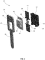
FIG. 1 is an exploded view illustrating a vertical surface mount device (SMD) pass-through fuse in accordance with an exemplary embodiment of the present disclosure in an unassembled state; -
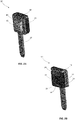
FIGS. 2A and 2B are front and rear perspective views illustrating the vertical SMD pass-through fuse shown inFIG. 1 in an assembled state; -
FIG. 3A is a cross sectional side view illustrating an alternative embodiment of the vertical SMD pass-through fuse shown inFIGS. 2A and 2B ; -
FIG. 3B is a cross sectional side view illustrating another alternative embodiment of the vertical SMD pass-through fuse shown inFIGS. 2A and 2B ; -
FIGS. 4A and 4B are perspective views illustrating the vertical SMD pass-through fuse shown inFIGS. 2A and 2B being installed on a printed circuit board; -
FIG. 5 is a side view illustrating another vertical SMD pass-through fuse in accordance with an exemplary embodiment of the present disclosure; -
FIG. 6 is a side view illustrating another vertical SMD pass-through fuse in accordance with an exemplary embodiment of the present disclosure; -
FIGS. 7A and 7B are front and rear perspective views illustrating another vertical SMD pass-through fuse in accordance with an exemplary embodiment of the present disclosure; -
FIG. 8 is a side view illustrating several vertical SMD pass-through fuses in accordance with alternative embodiments of the present disclosure; -
FIG. 9A is a front view illustrating a convenient packaging arrangement for caps in accordance with the present disclosure; -
FIG. 9B is a front view illustrating a convenient packaging arrangement for fuse plates in accordance with the present disclosure. - A vertical surface mount device (SMD) pass-through fuse in accordance with the present disclosure will now be described more fully with reference to the accompanying drawings, in which preferred embodiments of the vertical SMD pass-through fuse are presented. It will be understood, however, that the vertical SMD pass-through fuse may be embodied in many different forms and should not be construed as being limited to the embodiments set forth herein. Rather, these embodiments are provided so that this disclosure will convey certain exemplary aspects of the vertical SMD pass-through fuse to those skilled in the art.
- Referring to
FIGS. 1-2B , exploded and perspective views illustrating a vertical SMD pass-through fuse 10 (hereinafter "thefuse 10") in accordance with an exemplary, non-limiting embodiment of the present disclosure are shown. For the sake of convenience and clarity, terms such as "front," "rear," "top," "bottom," "above," "below," "vertical," "horizontal," "lateral," and "longitudinal" may be used herein to describe the relative placement and orientation of various components of thefuse 10, each with respect to the geometry and orientation of thefuse 10 as it appears inFIGS. 1-2B . Said terminology will include the words specifically mentioned, derivatives thereof, and words of similar import. - Referring to
FIG. 1 , thefuse 10, which is shown in an unassembled state, may include afuse body 12, afuse plate 14, acap 16, and alead frame 18. Thefuse body 12 may be a generally rectangular or block-shaped member formed of an electrically insulating material (e.g., plastic, polymer, ceramic, etc.) and may have acavity 20 formed in a front surface thereof. Thefuse body 12 may further include various surface features, protrusions, and contours for accommodating and retaining thefuse plate 14 as described in greater detail below. - The
fuse plate 14 may be a substantially planar member formed from a plate or sheet of electrically conductive material (e.g., stamped from a plate of zinc, copper, tin, etc.) and may include afusible element 22 extending between first andsecond terminals second terminals flanges 28 extending in opposite directions from lateral edges thereof for fitting within complementary recesses orgrooves 30 formed in the front edges of thefuse body 12. Mating engagement between theflanges 28 and thegrooves 30 may facilitate accurate location and secure engagement between thefuse plate 14 and thefuse body 12 when thefuse 10 is assembled (as shown inFIGS. 2A and 2B ), with thefusible element 22 extending over thecavity 20 in the front surface of thefuse body 12. Additionally, when theflanges 28 are disposed within thegrooves 30, thefuse plate 14 may be recessed relative to the front edges of thefuse body 12 with thefusible element 22 disposed within thecavity 20, thereby facilitating encapsulation of thefusible element 22 as further described below. - The
fusible element 22 may be configured to melt, disintegrate, or otherwise open if current flowing through thefuse plate 14 exceeds a predetermined threshold, or "current rating," of thefuse 10. In certain embodiments, thefusible element 22 may have a serpentine shape as shown inFIG. 1 . The present disclosure is not limited in this regard. In various embodiments, thefusible element 22 may include perforations, slots, thinned or narrowed segments, and/or various other features for making thefusible element 22 more susceptible to melting or opening relative to other portions of thefuse plate 14. In a non-limiting example, thefusible element 22 may be configured to have a current rating in a range between 2 amps and 80 amps. - The
cap 16 may be formed of an electrically insulating material (e.g., plastic, polymer, ceramic, etc.) and may include a substantially planer flangedportion 31 extending from acentral domed portion 32 that defines an interior cavity (not within view). When thefuse 10 is assembled, thecap 16 may fit over thefuse plate 14 and thefuse body 12, with theflanged portion 31 of thecap 16 engaging the front edges of thefuse body 12 and the withdomed portion 32 of thecap 16 covering thefusible element 22. Theflanged portion 31 of thecap 16 may be affixed to the front edges of thefuse body 12 via ultrasonic welding, laser welding, epoxy, etc. Thus, thefusible element 22 may be enclosed within, and may extend through, a chamber defined by thecap 16 and thefuse body 12, and the first andsecond terminals fuse body 12 and thecap 16. In various embodiments of thefuse 10, a fuse filler material, such as sand, silica, or the like (not shown), may be disposed within the chamber defined by thecap 16 and thefuse body 12 and may substantially surround thefusible element 22 for quenching electrical arcs that could otherwise propagate upon opening of thefusible element 22 during an overcurrent condition. - The
lead frame 18 may be formed from a single piece of electrically conductive material (e.g., stamped from a sheet of zinc, copper, tin, etc.) and may be generally key-shaped with anelongate shank portion 36 extending from the bottom of abow portion 38. Thebow portion 38 may have anaperture 40 formed therethrough and adapted to matingly receive thedomed portion 32 of thecap 16 as further described below. - Referring
FIGS. 2A and 2B , which illustrate thefuse 10 in a fully assembled state, the first andsecond fuse terminals fuse plate 14 may be bent or crimped around the top and bottom of thefuse body 12. Thecap 16 may be disposed over the fusible element 22 (not within view) and may be fastened to the front edges of thefuse body 12 as described above. Thebow portion 38 of thelead frame 18 may be disposed in flat abutment with the front of theflanged portion 31 of thecap 16, with thedomed portion 32 of thecap 16 extending through theaperture 40 in thebow portion 38. The top of thebow portion 38 may be bent or crimped around the top of thefuse body 12 and may be disposed in flat engagement with thefirst terminal 24 of thefuse plate 14 and may be electrically connected thereto. - In various embodiments, the
bow portion 38 may be connected to thefirst terminal 24 via brazing, high temperature solder, or other robust connection methods adapted to withstand high temperatures. Thus, during subsequent reflow soldering processes (such as may be performed during installation of thefuse 10, for example) the electrical connection between thebow portion 38 and thefirst terminal 24 will not be compromised. Alternatively, low temperature solder may be used to connect thebow portion 38 to thefirst terminal 24, and thebow portion 38 may be bent around the back and/or sides of thefuse body 12, as shown inFIG. 3A , for example, in a manner that traps the solder and prevents the solder from flowing out of the space between thebow portion 38 and thefirst terminal 24 when a subsequent reflow process is performed. In another contemplated embodiment shown inFIG. 3B , thebow portion 38 may have a hole ortrough 39 formed therethrough that is located directly above thefuse body 12 and thefirst terminal 24. A quantity of low temperature solder may be disposed within thehole 39 and may provide an electrical connection between thelead frame 18 and thefirst terminal 24. Since the bottom of thehole 39 is closed by thefirst terminal 24, the solder may be prevented from flowing out of thehole 39 when a subsequent reflow process is performed. More generally, in various embodiments of thefuse 10, thebow portion 38 may include any type of hole, cavity, recess, groove, pocket, channel, etc. formed entirely therethrough or in a bottom side thereof for holding a quantity of solder in contact with thefirst terminal 24 and retaining the quantity of solder when a subsequent reflow process is performed (e.g., during installation of thefuse 10 on a printed circuit board). - Referring to
FIGS. 4A and 4B , perspective views illustrating thefuse 10 being installed on a printed circuit board (PCB) 42 are shown (it will be appreciated that thefuse 10 can be similarly installed in various insulative substrates other than PCBs). Theshank portion 36 of thelead frame 18 may be inserted through a pass-throughslot 44 in thePCB 42 and may be secured therein via press-fit, adhesive, solder, etc., and thesecond terminal 26 of thefuse plate 14 may be disposed atop asolderable pad 46 on thePCB 42. Thesolderable pad 46 may be subsequently reflowed to establish a robust electrical connection with thesecond terminal 26. One or more traces or other electrical pathways (not shown) may extend from thesolderable pad 46 to other elements on thePCB 42, thereby placing such elements in electrical communication with thesecond terminal 26 of the fuse plate 14 (not within view). Aconductor 48 may be clipped or otherwise connected to theshank portion 36 of thelead frame 18 on the lower side of thePCB 42 and may provide an electrical connection between theshank portion 36 and an external electrical element (e.g., a source of electrical power such as a battery, not shown) to which theconductor 48 is connected. With thefuse 10 installed thusly, a conductive path is established that allows current to flow from theconductor 48 to theshank portion 36 of thelead frame 18, through thebow portion 38 of thelead frame 18 to thefirst terminal 24, through thefusible element 22 to thesecond terminal 26 and to connected electrical elements or devices on thePCB 42. Thus, thefuse 10 may provide overcurrent protection between the external electrical element (connected to theshank portion 36 of thelead frame 18 by the conductor 48) and one or more electrical elements on thePCB 42. - In view of the foregoing description, it will be appreciated that the
fuse 10 of the present disclosure provides numerous advantages relative to conventional SMD fuses. For example, a conventional SMD fuse, which may be substantially similar to thefuse 10 expect for the provision of theintegrated lead frame 18, is typically installed on a PCB in a horizontal orientation with its first and second terminals soldered to respective contacts on the PCB. By contrast, thefuse 10 of the present disclosure is disposed on a PCB in a vertical orientation (i.e., on its edge relative to conventional SMD fuses), with only one of its terminals (i.e., the second terminal 26) soldered to the PCB. The footprint of thefuse 10 on the PCB is therefore significantly smaller than that of conventional SMD fuses. Additionally, thelead frame 18 provides thefuse 10 with an integrated pass-through terminal, thereby obviating the need for connecting thefuse 10 to a separate pass-through terminal via a trace or conductor as required for conventional SMD fuses. Still further, inserting theshank portion 36 of thelead frame 18 through a pass-through slot in a PCB (as described above) facilitates a convenient and expeditious means for automatically and accurately placing thesecond terminal 26 of thefuse 10 on a solderable pad on the PCB. Still further, when thelead frame 18 and thesecond terminal 26 of thefuse 10 are installed on a PCB in the manner described above, they reinforce thecap 16 and thefuse body 12 against horizontal movement away from one another, thereby strengthening the coupling between thecap 16 and thefuse body 12 and increasing the breaking capacity of thefuse 10 relative to conventional SMD fuses. Still further, the vertical orientation of thefuse 10 moves thefusible element 22 away from a PCB or other substrate to which thefuse 10 is mounted, thereby providing the fuse with improved thermal management relative to conventional, horizontally-mounted SMD fuses. Thermal management is further improved by thelead frame 18 which may act as a heat sink for thefuse 10. - Referring to
FIG. 5 , a side view illustrating a vertical SMD pass-through fuse 100 (hereinafter "thefuse 100") in accordance with an alternative embodiment of the present disclosure is shown. Thefuse 100 may be substantially identical to thefuse 10 described above except that thefirst terminal 124 of thefuse plate 114 and thebow portion 138 of thelead frame 118 are not crimped over the top of thefuse body 112. Rather, thebow portion 138 of thelead frame 118 is straight (unbent) and coplanar with the rest of thelead frame 18, and thefirst terminal 124 of thefuse plate 114 is bent toward, and into flat engagement with, thebow portion 138. - Referring to
FIG. 6 , a side view illustrating a vertical SMD pass-through fuse 200 (hereinafter "thefuse 200") in accordance with another alternative embodiment of the present disclosure is shown. Thefuse 200 may be substantially identical to thefuse 100 described above except thatsecond terminal 226 of thefuse plate 214 is not crimped around the bottom of thefuse body 212. Rather, thesecond terminal 226 of thefuse plate 214 is unbent and extends straight down from thefuse body 212, parallel to theshank portion 236 of thelead frame 218. Thesecond terminal 226 may be inserted into, and electrically connected to (e.g., soldered to), a complementary slot or via in a PCB, for example. - Referring to
FIGS. 7A and 7B , front and rear perspective views illustrating a vertical SMD pass-through fuse 300 (hereinafter "thefuse 300") in accordance with another alternative embodiment of the present disclosure are shown. Thefuse 300 may be substantially identical to thefuse 10 described above except that thelead frame 318 may be disposed on a side or edge of thefuse body 312 instead of being disposed in flat engagement with the front of thecap 316. Thelead frame 318 may optionally include one ormore flanges cap 316 and the rear of thefuse body 312, respectively. Theflanges lead frame 318 and thefuse body 312 and may also hold thefuse body 312 and thecap 316 together, thereby improving the breaking capacity of thefuse 300. - Referring to
FIG. 8 ,alternative configurations fuses additional fuse configuration 400c resembling thefuse 10 described above but with the lead frame disposed on the rear of the fuse body, are presented in which the lead frames are bent or formed such that the fuses are disposed in a tilted or non-perpendicular orientation relative to a PCB. - Various components of the fuse embodiments described above may be manufactured and packaged in a manner that facilitates convenient shipping, dispensation, and installation thereof. For example, referring to
FIG. 9A , a plurality ofcaps 500 similar to thecap 16 described above may be manufactured using a conventional over-molding process, whereby the plurality ofcaps 500 are connected to one another by a molded carrier strip 502 (formed by/during the same over molding process used to form the caps 500) from which thecaps 500 may be subsequently removed. In another example shown inFIG. 9B , a plurality ofinterconnected fuse plates 504 similar to thefuse plate 14 described above may be manufactured using a conventional stamping process whereby the plurality ofinterconnected fuse plates 504 are simultaneously stamped from a single sheet of metal and can be subsequently separated from one another. - As used herein, an element or step recited in the singular and proceeded with the word "a" or "an" should be understood as not excluding plural elements or steps, unless such exclusion is explicitly recited. Furthermore, references to "one embodiment" of the present disclosure are not intended to be interpreted as excluding the existence of additional embodiments that also incorporate the recited features.
- While the present disclosure makes reference to certain embodiments, numerous modifications, alterations and changes to the described embodiments are possible without departing from the sphere and scope of the present disclosure, as defined in the appended claim(s). Accordingly, it is intended that the present disclosure not be limited to the described embodiments, but that it has the full scope defined by the language of the following claims, and equivalents thereof.
Claims (15)
- A vertical surface mount device (SMD) pass-through fuse comprising:an electrically insulating fuse body;a fusible element disposed on a first side of the fuse body and extending between first and second terminals;an electrically insulating cap having a domed portion and a flanged portion extending from the domed portion, the domed portion disposed over the fusible element, and the flanged portion affixed to the fuse body; anda conductive lead frame having a bow portion and an elongate shank portion extending from the bow portion, wherein the bow portion is disposed on the cap and is connected to the first terminal, and wherein the shank portion extends away from the fuse body.
- The vertical SMD pass-through fuse of claim 1, wherein the first terminal has a bent portion that extends around a first end of the fuse body and wherein the bow portion of the lead frame has a bent portion that extends over the bent portion of the first terminal.
- The vertical SMD pass-through fuse of claim 1 or 2, wherein the second terminal has a bent portion that extends around a second end of the fuse body.
- The vertical SMD pass-through fuse of claim 2 or 3, wherein the bent portion of the bow portion extends to a second side of the fuse body opposite the first side of the fuse body, and/or wherein the bent portion of the bow portion has an aperture formed therethrough for receiving solder.
- The vertical SMD pass-through fuse of any of the preceding claims with one or more of the following:wherein the domed portion of the cap extends through an aperture in the bow portion of the lead frame;wherein the first terminal is disposed in flat engagement with the bow portion of the lead frame and is parallel to the shank portion of the lead frame;wherein the second terminal extends away from the fuse body and is parallel to the shank portion of the lead frame.
- The vertical SMD pass-through fuse of any of the preceding claims, wherein the lead frame has a first flange extending from the bow portion that engages the cap and a second flange extending from the bow portion that engages a second side of the fuse body opposite the first side of the fuse body.
- The vertical SMD pass-through fuse of any of the preceding claims,
wherein the first and second terminals have flanges extending from opposing sides thereof that fit into corresponding grooves in the first side of the fuse body, and/or
wherein the fusible element extends over a cavity in the first side of the fuse body. - A vertical surface mount device (SMD) pass-through fuse comprising:an electrically insulating fuse body;a fusible element disposed on a first side of the fuse body and extending over a cavity in the first side of the fuse body between first and second terminals;an electrically insulating cap having a domed portion and a flanged portion extending from the domed portion, the domed portion disposed over the fusible element and the cavity, and the flanged portion affixed to the fuse body; anda conductive lead frame having a bow portion and an elongate shank portion extending from the bow portion, wherein the bow portion is disposed in flat engagement with the shank portion of the cap, with the domed portion of the cap extending through an aperture in the bow portion, the bow portion being connected to the first terminal and the shank portion extending away from the fuse body.
- The vertical SMD pass-through fuse of claim 8, wherein the first terminal has a bent portion that extends around a first end of the fuse body and wherein the bow portion of the lead frame has a bent portion that extends over the bent portion of the first terminal.
- The vertical SMD pass-through fuse of claim 8 or 9 with one or more of the following:wherein the second terminal has a bent portion that extends around a second end of the fuse body;wherein the bent portion of the bow portion extends to a second side of the fuse body opposite the first side of the fuse body;wherein the bent portion of the bow portion has an aperture formed therethrough for receiving solder.
- The vertical SMD pass-through fuse of any of the claims 8 to 10, wherein the first terminal is disposed in flat engagement with the bow portion of the lead frame and is parallel to the shank portion of the lead frame.
- The vertical SMD pass-through fuse of any of the claims 8 to 11, wherein the second terminal extends away from the fuse body and is parallel to the shank portion of the lead frame.
- The vertical SMD pass-through fuse of any of the claims 8 to 12, wherein the lead frame has a first flange extending from the bow portion that engages the cap and a second flange extending from the bow portion that engages a second side of the fuse body opposite the first side of the fuse body.
- The vertical SMD pass-through fuse of any of the claims 8 to 13, wherein the first and second terminals have flanges extending from opposing sides thereof that fit into corresponding grooves in the first side of the fuse body.
- Use of a vertical SMD pass through fuse according to any of the preceding claims for circuit protection.
Applications Claiming Priority (1)
| Application Number | Priority Date | Filing Date | Title |
|---|---|---|---|
| US201962883229P | 2019-08-06 | 2019-08-06 |
Publications (1)
| Publication Number | Publication Date |
|---|---|
| EP3772779A1 true EP3772779A1 (en) | 2021-02-10 |
Family
ID=71894704
Family Applications (1)
| Application Number | Title | Priority Date | Filing Date |
|---|---|---|---|
| EP20188673.6A Pending EP3772779A1 (en) | 2019-08-06 | 2020-07-30 | Vertical surface mount device pass-through fuse |
Country Status (4)
| Country | Link |
|---|---|
| US (1) | US11081308B2 (en) |
| EP (1) | EP3772779A1 (en) |
| JP (1) | JP7582744B2 (en) |
| CN (1) | CN112349561B (en) |
Families Citing this family (1)
| Publication number | Priority date | Publication date | Assignee | Title |
|---|---|---|---|---|
| WO2024198008A1 (en) * | 2023-03-30 | 2024-10-03 | 惠州亿纬锂能股份有限公司 | Circuit protection structure, circuit assembly, packaging method therefor, and ccs assembly |
Citations (5)
| Publication number | Priority date | Publication date | Assignee | Title |
|---|---|---|---|---|
| DE10062962A1 (en) * | 2000-12-16 | 2002-07-25 | Bosch Gmbh Robert | Holding device for fastening an electrical component like a capacitor on a supporting substrate has a holder for the component and wiring for making a connection between the component's connectors and contacts on the substrate. |
| US20050195547A1 (en) * | 2004-03-05 | 2005-09-08 | Shang-Lung Huang | Structure of safety power adapter |
| US20070099448A1 (en) * | 2005-11-01 | 2007-05-03 | Tyco Electronics Corporation | Electrical device carrier contact assembly |
| WO2015039713A1 (en) * | 2013-09-19 | 2015-03-26 | Wabco Gmbh | Contact system for plug-in connections on electronics housings |
| DE202015100736U1 (en) * | 2015-02-16 | 2016-05-18 | Leoni Bordnetz-Systeme Gmbh | Electrical connector and connector for such |
Family Cites Families (15)
| Publication number | Priority date | Publication date | Assignee | Title |
|---|---|---|---|---|
| US5113168A (en) * | 1991-06-26 | 1992-05-12 | San-O Industrial Corporation | Single position flat mount fuse holder |
| JPH0964504A (en) * | 1995-08-21 | 1997-03-07 | Sony Corp | Hybrid IC with lead frame and mother IC mounting method for hybrid IC |
| JP3447443B2 (en) * | 1995-10-02 | 2003-09-16 | ローム株式会社 | Structure of surface mount type solid electrolytic capacitor with safety fuse |
| US5889658A (en) * | 1997-11-25 | 1999-03-30 | Motorola, Inc. | Package assembly for an electronic component |
| US6700081B1 (en) * | 2002-11-18 | 2004-03-02 | Rockwell Automation Technologies, Inc. | Fuse block with door sensing rotary disconnect |
| WO2005124808A1 (en) * | 2004-06-18 | 2005-12-29 | Alpi Co., Ltd. | Fuse device |
| KR100689021B1 (en) * | 2004-12-17 | 2007-03-12 | 스마트전자 주식회사 | Surface-Mount Small Fuse and Manufacturing Method Thereof |
| US8665057B2 (en) * | 2005-03-31 | 2014-03-04 | Conti Temic Microelectronic Gmbh | Electronic assembly having stressable contact bridge with fuse function |
| KR20080023531A (en) * | 2006-09-11 | 2008-03-14 | 삼성전자주식회사 | Fuse Capacity Display |
| TW201036024A (en) * | 2009-03-27 | 2010-10-01 | qiong-zhang Yan | Manufacturing process of fuse base and product thereof |
| JP6051947B2 (en) * | 2013-02-28 | 2016-12-27 | 株式会社デンソー | Electronic component and electronic control device |
| US9824842B2 (en) * | 2015-01-22 | 2017-11-21 | Littelfuse, Inc. | Wire in air split fuse with built-in arc quencher |
| JP6620404B2 (en) * | 2015-03-03 | 2019-12-18 | Tdk株式会社 | Electronic components |
| US10283307B2 (en) * | 2017-04-05 | 2019-05-07 | Littelfuse, Inc. | Surface mount fuse |
| DE102017214682B4 (en) * | 2017-08-22 | 2019-03-07 | Leoni Bordnetz-Systeme Gmbh | Electrical fuse element and circuit board with electrical fuse element soldered thereto |
-
2020
- 2020-07-29 US US16/942,169 patent/US11081308B2/en not_active Expired - Fee Related
- 2020-07-30 EP EP20188673.6A patent/EP3772779A1/en active Pending
- 2020-08-06 CN CN202010782105.2A patent/CN112349561B/en active Active
- 2020-08-06 JP JP2020134177A patent/JP7582744B2/en active Active
Patent Citations (5)
| Publication number | Priority date | Publication date | Assignee | Title |
|---|---|---|---|---|
| DE10062962A1 (en) * | 2000-12-16 | 2002-07-25 | Bosch Gmbh Robert | Holding device for fastening an electrical component like a capacitor on a supporting substrate has a holder for the component and wiring for making a connection between the component's connectors and contacts on the substrate. |
| US20050195547A1 (en) * | 2004-03-05 | 2005-09-08 | Shang-Lung Huang | Structure of safety power adapter |
| US20070099448A1 (en) * | 2005-11-01 | 2007-05-03 | Tyco Electronics Corporation | Electrical device carrier contact assembly |
| WO2015039713A1 (en) * | 2013-09-19 | 2015-03-26 | Wabco Gmbh | Contact system for plug-in connections on electronics housings |
| DE202015100736U1 (en) * | 2015-02-16 | 2016-05-18 | Leoni Bordnetz-Systeme Gmbh | Electrical connector and connector for such |
Also Published As
| Publication number | Publication date |
|---|---|
| CN112349561A (en) | 2021-02-09 |
| US11081308B2 (en) | 2021-08-03 |
| CN112349561B (en) | 2024-10-11 |
| JP2021027047A (en) | 2021-02-22 |
| US20210043408A1 (en) | 2021-02-11 |
| JP7582744B2 (en) | 2024-11-13 |
Similar Documents
| Publication | Publication Date | Title |
|---|---|---|
| US10490379B2 (en) | Surface mount fuse | |
| EP3599800B1 (en) | Connector-fitting structure of flexible printed circuit | |
| TWI475590B (en) | Subminiature fuse with surface mount end caps and improved connectivity | |
| CN212622762U (en) | Passive current sensor and components therefor | |
| US5459641A (en) | Polar electronic component and mounting structure therefor | |
| CN102214871B (en) | Connector shell | |
| JPH104250A (en) | Printed circuit board and method of assembling and soldering electronic components to printed circuit board | |
| JP2006005096A (en) | Circuit structure | |
| CN109103401B (en) | Welding structure | |
| US11081308B2 (en) | Vertical surface mount device pass-through fuse | |
| US8710377B2 (en) | Electric connection box | |
| JP5765674B2 (en) | Spring connector and how to assemble this spring connector | |
| US20050064745A1 (en) | Terminal for electrical connector | |
| US6769924B1 (en) | Electrical connector having a releasable cover | |
| US7121848B2 (en) | Battery connector | |
| CN108232497B (en) | Electronic device | |
| CN121195325A (en) | Electronic component unit and manufacturing method of electronic component unit | |
| US11380507B2 (en) | Substrate surface-mounted fuse | |
| US6929498B2 (en) | Electrical connector with mounting member and method of making same | |
| JP2020038883A (en) | Circuit structure and method of manufacturing circuit structure | |
| CN210805748U (en) | Solid state relay | |
| KR20170132581A (en) | Thermal fuse and printed circuit board thereof | |
| JP2000340471A (en) | Chip-type electrolytic capacitor and seat plate therefor | |
| JP2002367496A (en) | Thermal fuse | |
| JP3074595U (en) | Board mounted type high breaking capacity small fuse |
Legal Events
| Date | Code | Title | Description |
|---|---|---|---|
| PUAI | Public reference made under article 153(3) epc to a published international application that has entered the european phase |
Free format text: ORIGINAL CODE: 0009012 |
|
| STAA | Information on the status of an ep patent application or granted ep patent |
Free format text: STATUS: THE APPLICATION HAS BEEN PUBLISHED |
|
| AK | Designated contracting states |
Kind code of ref document: A1 Designated state(s): AL AT BE BG CH CY CZ DE DK EE ES FI FR GB GR HR HU IE IS IT LI LT LU LV MC MK MT NL NO PL PT RO RS SE SI SK SM TR |
|
| AX | Request for extension of the european patent |
Extension state: BA ME |
|
| STAA | Information on the status of an ep patent application or granted ep patent |
Free format text: STATUS: REQUEST FOR EXAMINATION WAS MADE |
|
| 17P | Request for examination filed |
Effective date: 20210805 |
|
| RBV | Designated contracting states (corrected) |
Designated state(s): AL AT BE BG CH CY CZ DE DK EE ES FI FR GB GR HR HU IE IS IT LI LT LU LV MC MK MT NL NO PL PT RO RS SE SI SK SM TR |
|
| STAA | Information on the status of an ep patent application or granted ep patent |
Free format text: STATUS: EXAMINATION IS IN PROGRESS |
|
| 17Q | First examination report despatched |
Effective date: 20230105 |
|
| STAA | Information on the status of an ep patent application or granted ep patent |
Free format text: STATUS: THE APPLICATION IS DEEMED TO BE WITHDRAWN |